DESIGN AND DEVELOPMENT OF MICRO UPSET WELDING SETUP · DESIGN AND DEVELOPMENT OF MICRO UPSET...
8
DESIGN AND DEVELOPMENT OF MICRO UPSET WELDING SETUP Gurjeet Singh 1 * and Nitin Arora 1 *Corresponding Author: Gurjeet Singh, [email protected] Designing and constructing resistance welding machines involves a combination of electrical design, machine structures, mechanisms and controls. The machines vary from simple mechanisms to exceptionally complicated units. Monitoring the condition of large upset welding machines in operating industries has attracted increasing interest in recent years owing to the need for decreasing the energy consumption on production machinery and for reducing the extent of secondary damage caused by failures. Upset Welding (UW) is a resistance welding process utilizing both heat and deformation to form a weld. A micro-setup would certainly reduce heat consumption and offer greater efficiency. In this paper an electro-mechanical micro upset welding setup is constructed following the fundamental principles of resistance welding. The chief electrical and mechanical components used are single phase ac transformer, welding arms or copper alloy electrodes, externally threaded steel shaft, frame, multimeter and control switches. After the construction of the micro welder, two thin sheets of mild steel are welded. Keywords: Upset welding, Electro-mechanical, Micro setup, Threaded shaft INTRODUCTION Resistance welding is a group of welding processes in which coalescence is produced by the heat obtained from resistance of the work to electric current in a circuit of which the work is a part and by the application of pressure (Althouse et al., 1980). There are at least seven important resistance-welding processes. These are flash welding, high frequency resistance welding, percussion ISSN 2278 – 0149 www.ijmerr.com Vol. 2, No. 2, April 2013 © 2013 IJMERR. All Rights Reserved Int. J. Mech. Eng. & Rob. Res. 2013 1 Department of Production Engineering, Birla Institute of Technology, Mesra, Ranchi, India. welding, projection welding, resistance seam welding, resistance spot welding, and upset welding. Three factors involved in making a resistance weld are: • The amount of current that passes through the work, • The pressure that the electrodes transfer to the work, and • The time the current flows through the work. Research Paper
Transcript of DESIGN AND DEVELOPMENT OF MICRO UPSET WELDING SETUP · DESIGN AND DEVELOPMENT OF MICRO UPSET...

51
Int. J. Mech. Eng. & Rob. Res. 2013 Gurjeet Singh and Nitin Arora, 2013
DESIGN AND DEVELOPMENT OF MICRO UPSETWELDING SETUP
Gurjeet Singh1* and Nitin Arora1
*Corresponding Author: Gurjeet Singh,[email protected]
Designing and constructing resistance welding machines involves a combination of electricaldesign, machine structures, mechanisms and controls. The machines vary from simplemechanisms to exceptionally complicated units. Monitoring the condition of large upset weldingmachines in operating industries has attracted increasing interest in recent years owing to theneed for decreasing the energy consumption on production machinery and for reducing theextent of secondary damage caused by failures. Upset Welding (UW) is a resistance weldingprocess utilizing both heat and deformation to form a weld. A micro-setup would certainly reduceheat consumption and offer greater efficiency. In this paper an electro-mechanical micro upsetwelding setup is constructed following the fundamental principles of resistance welding. Thechief electrical and mechanical components used are single phase ac transformer, weldingarms or copper alloy electrodes, externally threaded steel shaft, frame, multimeter and controlswitches. After the construction of the micro welder, two thin sheets of mild steel are welded.
Keywords: Upset welding, Electro-mechanical, Micro setup, Threaded shaft
INTRODUCTIONResistance welding is a group of weldingprocesses in which coalescence is producedby the heat obtained from resistance of thework to electric current in a circuit of which thework is a part and by the application ofpressure (Althouse et al., 1980). There are atleast seven important resistance-weldingprocesses. These are flash welding, highfrequency resistance welding, percussion
ISSN 2278 – 0149 www.ijmerr.comVol. 2, No. 2, April 2013
© 2013 IJMERR. All Rights Reserved
Int. J. Mech. Eng. & Rob. Res. 2013
1 Department of Production Engineering, Birla Institute of Technology, Mesra, Ranchi, India.
welding, projection welding, resistance seamwelding, resistance spot welding, and upsetwelding. Three factors involved in making aresistance weld are:
• The amount of current that passes throughthe work,
• The pressure that the electrodes transfer tothe work, and
• The time the current flows through the work.
Research Paper
52
Int. J. Mech. Eng. & Rob. Res. 2013 Gurjeet Singh and Nitin Arora, 2013
Heat is generated by the passage ofelectrical current through a resistance circuit.The force applied before, during, and after thecurrent flow forces the heated parts togetherso that coalescence will occur. Pressure isrequired throughout the entire welding cycleto assure a continuous electrical circuit throughthe work.
I is the current in amperes, E is the voltagein volts, and R is the resistance of the materialin ohms. The total energy is expressed by theformula: Energy equals I E T in which T isthe time in seconds during which current flowsin the circuit: H (heat energy) = I2 R T. Forpractical reasons a factor which relates to heatlosses should be included; therefore, the actualresistance welding formula is: H (heat energy)= I2 R T K.
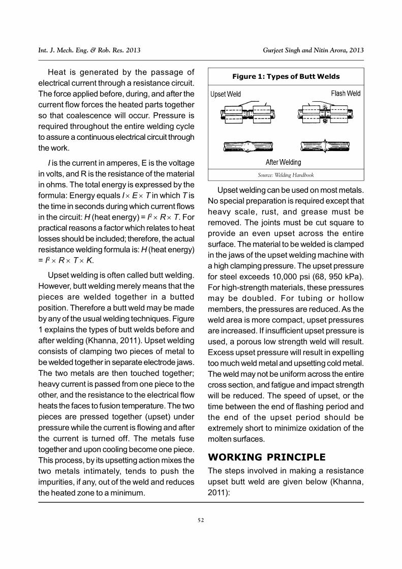
Upset welding is often called butt welding.However, butt welding merely means that thepieces are welded together in a buttedposition. Therefore a butt weld may be madeby any of the usual welding techniques. Figure1 explains the types of butt welds before andafter welding (Khanna, 2011). Upset weldingconsists of clamping two pieces of metal tobe welded together in separate electrode jaws.The two metals are then touched together;heavy current is passed from one piece to theother, and the resistance to the electrical flowheats the faces to fusion temperature. The twopieces are pressed together (upset) underpressure while the current is flowing and afterthe current is turned off. The metals fusetogether and upon cooling become one piece.This process, by its upsetting action mixes thetwo metals intimately, tends to push theimpurities, if any, out of the weld and reducesthe heated zone to a minimum.
Upset welding can be used on most metals.No special preparation is required except thatheavy scale, rust, and grease must beremoved. The joints must be cut square toprovide an even upset across the entiresurface. The material to be welded is clampedin the jaws of the upset welding machine witha high clamping pressure. The upset pressurefor steel exceeds 10,000 psi (68, 950 kPa).For high-strength materials, these pressuresmay be doubled. For tubing or hollowmembers, the pressures are reduced. As theweld area is more compact, upset pressuresare increased. If insufficient upset pressure isused, a porous low strength weld will result.Excess upset pressure will result in expellingtoo much weld metal and upsetting cold metal.The weld may not be uniform across the entirecross section, and fatigue and impact strengthwill be reduced. The speed of upset, or thetime between the end of flashing period andthe end of the upset period should beextremely short to minimize oxidation of themolten surfaces.
WORKING PRINCIPLEThe steps involved in making a resistanceupset butt weld are given below (Khanna,2011):
Figure 1: Types of Butt Welds
Source: Welding Handbook

53
Int. J. Mech. Eng. & Rob. Res. 2013 Gurjeet Singh and Nitin Arora, 2013
• The two pieces to be butt welded aregripped firmly, one in each clamp and arecorrectly aligned so that when brought intocontact one with the other by sliding themovable clamp to the fixed one, they fittogether exactly.
• Force is applied so that the faces of twopieces touch together and remain underpressure.
• A heavy current is then passed from onepiece to another. The resistance to theelectrical current flow heats the faces tofusion temperature.
• Both pressure and current are appliedthroughout the weld cycle and when thefaces (or ends) of the pieces becomeplastic, they are pressed together morefirmly, upsetting the metal pieces to form adense joint. Upsetting takes place while thecurrent is flowing and continues until afterthe current is switched off.
• The welding current is switched off.
• Upsetting force is released as the weldedjoint has cooled to the desired temperature.
• Work pieces are unclamped. Figures 2 and3 explains the working principle clearly.
WELD CYCLEThe complete sequence of events involved inmaking a resistance weld is shown in Figures4 and 5.
The weld cycle has three stages: squeezetime, weld time, hold time.
1. The electrodes come together, bring thecomponents together and apply a force. Thisforce builds up and requires a certain length
Figure 2: Principles of Upset Butt WeldingCourtesy of TWI Ltd.
Figure 3: Upset Welding: Basic Mechanism
Source: Materials & Design and Welding Handbook
Figure 4: Schematic of Typical Butt WeldCycle
Source: Welding Journal

54
Int. J. Mech. Eng. & Rob. Res. 2013 Gurjeet Singh and Nitin Arora, 2013
of time, called the “squeeze time”, to buildup to a value where welding can take place.
2. The welding current is applied for the “weldtime” which typically lasts for a few cyclesof the mains frequency.
3. The electrode force is maintained during the“hold time” whilst the weld nugget is allowedto solidify and cool.
CONSTRUCTION DETAILS OFUPSET BUTT WELDINGSETUPThe components required for the micro upsetwelding setup can be divided into twocategories:
1. Mechanical Components.
2. Electrical/Electronic Components.
Mechanical Components
Electrode Clamps (Khanna, 2011)
An upset welder consists of clamps suitablymounted on a horizontal slide, one being fixedrigidly and the other movable. Both clamps aremade of conducting material (Cu-alloy like
brass) and are connected to the secondary ofthe transformer. There are certainrequirements which these electrodes mustpossess. They must:
• Be a good conductor of electricity.
• Be a good conductor of heat.
• Have good mechanical strength andhardness.
• Have a minimum tendency to alloy(combine) with the metals being welded.
For the welding of steel copper alloys aregenerally used for the manufacture of theelectrode clamps. For aluminium, however,steel, sometimes copper plated, has beenfound to give better results, conducting lessheat away from the weld, providing a longerlife and more positive clamping.
Weldable Metals/Workpiece(Althouse et al., 1980)
Metals that are weldable, the thicknesses thatcan be welded and joint design are related tospecific resistance welding processes.
Difficulties may be encountered whenwelding certain metals in thicker sections.Some metals require heat treatment afterwelding for satisfactory mechanical properties.Weld ability is controlled by three factors:resistivity, thermal conductivity, and meltingtemperature. Metals with a high resistance tocurrent flow and with a low thermal conductivityand a relatively low melting temperature wouldbe easily weldable. Ferrous metals all fall intothis category. Metals that have a lowerresistivity but a higher thermal conductivity willbe slightly more difficult to weld. This includesthe light metals, aluminium and magnesium.Table 1 shows the list of weldable metals.
Figure 5: Basic Single Impulse WeldingCycle
Source: Assembly and Automation In Focus

55
Int. J. Mech. Eng. & Rob. Res. 2013 Gurjeet Singh and Nitin Arora, 2013
For micro upset welding the workpieceselected are thin sheets of mild steel (about3 mm in thickness) because of its high weldability, low thermal conductivity and highelectrical resistivity.
Specific Heat of mild steel S = 0.49 KJ/kgK
Resistivity/Specific Resistance of mild steel = 1.18 10–7 m
Melting Temperature of mild steel T = (1225– 1440 °C)
Externally Threaded Steel Shaft,Steel Handle and Collar Head
An externally threaded steel shaft is rotatedmanually to move one of the copper electrodeshorizontally along the steel plate until the twoworkpieces touch each other. The handle isattached to the shaft using cotter joint. Thewhole setup is placed on a wooden base. Themechanism followed is similar to the benchvice clamping mechanism. Figure 6 shows thefinal design setup.
ELECTRICAL/ELECTRONICCOMPONENTSStep-Down Transformer/WeldingTransformer (Althouse et al.,1980)
It provides the electrical current for heating.Control of secondary current is achieved bytransformer tap switches or electronic phase-shift devices. In a step-down transformernumber of turns in primary winding is greaterthan number of turns in secondary winding, i.e.,N1 > N2 since [V1/V2 = N1/N2] where V1 isthe primary voltage and V2 is the secondaryvoltage. The basis of the upset weldingmachine is an AC transformer, the majority ofproduction equipment being single phasemachines. The capacity of the machine islimited by the current requirements of the jointand the upset pressure available. The powerdemanded of the transformer is based on thecross-sectional area of the faces. The varyingelectrical conductivity of the different alloys alsohas an effect on power requirements.
The current requirements for upset buttwelding ranges from around 2500 to 5500 A.Voltages vary from 2 volts at a low cross-
Base Metal Weldability
Aluminums Weldable
Magnesium Weldable
Inconel Weldable
Nickel Weldable
Nickel Silver Weldable
Monel Weldable
Precious Metals Weldable
Low Carbon Steel Weldable
Low Alloy Steel Weldable
High and Medium Carbon Possible But Not Popular
Alloy Steel Possible But Not Popular
Stainless Steel Weldable
Table 1: List of Weldable Metals Figure 6: Final Design Setupof Micro-Upset Welder
56
Int. J. Mech. Eng. & Rob. Res. 2013 Gurjeet Singh and Nitin Arora, 2013
sectional area to 20 volts for the thickersections.
The welding transformer is rated on aspecified input and not on the output like othertransformers. It is usually rated at 50% dutycycle, which means that it should be used inactually creating welds 30 seconds out of each60 seconds, 10 seconds out of 20 seconds,or any segment of time where the idle time atleast equals the weld time. The KVA is the inputor primary circuit rating. For example, with a230 volt input and 43.48 amperes flowing, themachine would be rated at 10 KVA (230 43.48 = 10,000.40 VA).
Controls
Controls for resistance welding machines varyfrom simple hand adjustments and switchesto precise electronic controls. The variablesof resistance welding can all be controlledmanually or automatically (Althouse et al.,1980). These variables are:
• Current
• Pressure
• Time
The current may be manually adjusted bythe primary steps on the transformer.
The pressure of the electrodes on the metalbeing welded can be controlled by theoperator ’s pressure on the lever,semiautomatically controlled by the use ofadjustable springs, or automatically controlledby hydraulic or pneumatic pressure and thesize of the cylinders.
The time that the current flows and the timethe pressure is imposed can be manuallycontrolled on simple machines. The more
automatic machines use electronic timers thatfunction on the basis of the number of AC cyclesthat pass through the circuit such as:
• Pressure applied for 20 cycles (SqueezeTime).
• Current flows for 6 cycles (Weld Time).
• Current off-pressure maintained for 15cycles (Hold Time).
Multimeter
It is used to measure the electric current andvoltage across the metal to be welded. Multimeteris very essential instrument in order to pass thecurrent in the circuit in a desired range.
Connecting wires, tap switches and wirenuts are a few secondary electricalcomponents used in constructing the micro-upset welding setup. Figure 7 shows theelectrical circuit diagram of micro welder.
GOOD UPSET BUTT WELD ISOBTAINED IF (KHANNA, 2011)• Faces to be butt welded are clean, parallel
and reasonably smooth.
• The two workpieces are equal in cross-sectional area and of equal specificresistance. If the two pieces are of unequalspecific resistance, the part having thelesser resistance should project farther fromthe clamping die than the other. Similarly, ifthe two pieces have equal specificresistance, but unequal area of cross-section, one with the larger cross-sectionalarea should project from the clamping diefarther than the other part.
• To facilitate heating at the abutting surfaces,the areas are sometimes restricted bybevelling the ends.

57
Int. J. Mech. Eng. & Rob. Res. 2013 Gurjeet Singh and Nitin Arora, 2013
RESULTSThe current design setup is referred to as amicro setup since it offers upset welding of verythin sheets of steel with minimum requirementof energy contrary to the conventional upsetwelders that are less energy efficient and arerestricted to larger size of workpieces. Upsetwelding typically results in solid-state weldswith no melting at the joint. The effect ofprocess parameters including heating andpost-weld heating power and their
corresponding duration along with interference,on the tensile strength of the welded joint arebeing experimentally investigated.
After the welding of ½ inch rectangularsteel bars the results obtained are shown inTable 2.
CONCLUSIONRecent developments in upset welding includethe use of pulsing of the current in order toreduce metal expulsion and to improvedperformance when welding coated material.Tong size varies in length and may be air orwater cooled. This process is commonlymarried to robotics and lends itself to thejoining of thin coated material utilized in theautomotive industry. It produces high qualityjoining at a very rapid pace and is typicallyutilized to join base materials that are less than¼” (6 mm) in thickness. In resistance upsetwelding, the heat is generated by resistanceof the interface of abutting surfaces to the flowof electrical current in heating and post-weldheating stages.
The applications of Upset Welding (Khanna,2011) are tremendous and some of whichinclude welding of:
• Chains,
• Rails,
• Pipelines,
• Wheel rims,
• Rings made of steel strip and
• Bar welding.
Upset welding is used in wire mills and inthe manufacture of products made from wire.In wire mill applications, the process is used
Figure 7: Electrical Circuit Diagramof Micro Upset Welder
19 3 0.79
14 6 1.6
12 9 2.4
10 11 3.2
8 14 3.9
7.5 17 4.5
7 20 5.5
Table 2: Upset Butt Welding Energyand Time
PowerRequired (KW)
Time Needed(sec)
DistanceBetween TwoWorkpieces
(inches)
58
Int. J. Mech. Eng. & Rob. Res. 2013 Gurjeet Singh and Nitin Arora, 2013
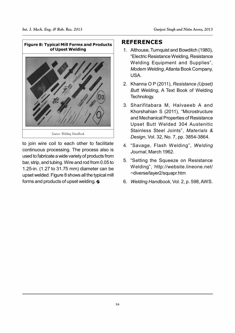
to join wire coil to each other to facilitatecontinuous processing. The process also isused to fabricate a wide variety of products frombar, strip, and tubing. Wire and rod from 0.05 to1.25-in. (1.27 to 31.75 mm) diameter can beupset welded. Figure 8 shows all the typical millforms and products of upset welding.
Figure 8: Typical Mill Forms and Productsof Upset Welding
Source: Welding Handbook
REFERENCES1. Althouse, Turnquist and Bowditch (1980),
“Electric Resistance Welding, ResistanceWelding Equipment and Supplies”,Modern Welding, Atlanta Book Company,USA.
2. Khanna O P (2011), Resistance (Upset)Butt Welding, A Text Book of WeldingTechnology.
3. Sharif itabara M, Halvaeeb A andKhorshahian S (2011), “Microstructureand Mechanical Properties of ResistanceUpset Butt Welded 304 AusteniticStainless Steel Joints”, Materials &Design, Vol. 32, No. 7, pp. 3854-3864.
4. “Savage, Flash Welding”, WeldingJournal, March 1962.
5. “Setting the Squeeze on ResistanceWelding”, http://website.lineone.net/~diverse/layer2/squapr.htm
6. Welding Handbook, Vol. 2, p. 598, AWS.