Design and Development of ALMA Band 4 Cartridge · PDF file · 2009-04-20separating...
6
Design and Development of ALMA Band 4 Cartridge Receiver Shin’ichiro Asayama * , Susumu Kawashima, Hiroyuki Iwashita, Toshikazu Takahashi, Motoko Inata, Yoshiyuki Obuchi, Takakiyo Suzuki, and Toru Wada Advanced Technology Center and ALMA-J project office, National Astronomical Observatory of Japan * Contact: [email protected], phone +81-422-34-3931 Abstract— This paper describes the design and development of the ALMA Band 4 cartridge receiver. Band 4 is one of the ten bands that will form the ALMA Front End Receiver. It receives radiation in the 125-163 GHz frequency range in two orthogonal polarizations and down-converts the sideband separated signals to intermediate frequencies between 4 and 8 GHz. I.INTRODUCTION The Atacama Large Millimeter/Submillimeter Array (ALMA) is an international collaboration between Europe, Japan and North America, in cooperation with the Republic of Chile with its full-operation expected in 2012 [1]. Taiwan is also contributing to ALMA as a partner of Japan. ALMA will be located on the Chajnantor plain of the Chilean Andes in the District of San Pedro de Atacama, 5,000 meters above sea level. The ALMA receiver system will cover all the available atmospheric frequency windows between 30 GHz and 950 GHz. The range shall be covered in 10 bands with HEMT or SIS devices. The receiver should be modular so that one easy to install self-contained receiver should cover that one particular frequency band. These self-contained receivers are known as "cartridges". The development and production of the Band 4 cartridge receivers is one portion of the Japanese in-kind contribution to ALMA. II.RECEIVER OVERVIEW ALMA Band 4 will operate in the 125-163 GHz frequency band, which is 26 % bandwidth to the center frequency of 144 GHz. A layout of the Band 4 cartridge receiver and a photograph of the assembled cartridge are shown in Fig. 1 and Fig. 2, respectively. Band 4 receivers are made on the small 140mm diameter cartridges developed by Rutherford Appleton Laboratory (RAL). It is a dual polarization receiver, which uses an orthomode transducer (OMT) as a polarization splitter. The cartridge consists of three stages (at operating temperatures 4, 15, and 110 K) and the base-plate (which acts as a vacuum seal) at 300 K, with GFRP 10 spacers between them. The 110 K stage has the LO doublers mounted on it and heat sinks for the LO waveguide, coax cables and wiring. The 15 K stage has only heat sinks for the LO waveguide, coax cables and wiring attached. The 4 K stage has the Corrugated horn, OMT, optics support structure, sideband- separating SIS mixer units, Cryogenic Isolators, Cryogenic HEMT Amplifiers, and heat sinks for the LO waveguide, coax cable and wiring attached. Fig.1 Layout of the ALMA Band 4 cartridge receiver. DC wire harnesses are not illustrated OMT Sideband-Separating SIS mixer Unit Isolator HEMT Amp Doubler 110K Stage 15K Stage 4K Stage ESD Protection Board Corrugated Horn Optics Support Structure Vacuum Flange (300 K) LO WG (WR-12) Stainless Steel IF Cable LO WG (WR-06) 19th International Symposium on Space Terahertz Technology, Groningen, 28-30 April 2008 244
Transcript of Design and Development of ALMA Band 4 Cartridge · PDF file · 2009-04-20separating...

Design and Development of ALMA Band 4 Cartridge Receiver
Shin’ichiro Asayama*, Susumu Kawashima, Hiroyuki Iwashita, Toshikazu Takahashi,
Motoko Inata, Yoshiyuki Obuchi, Takakiyo Suzuki, and Toru Wada
Advanced Technology Center and ALMA-J project office, National Astronomical Observatory of Japan * Contact: [email protected], phone +81-422-34-3931
Abstract— This paper describes the design and development of the ALMA Band 4 cartridge receiver. Band 4 is one of the ten bands that will form the ALMA Front End Receiver. It receives radiation in the 125-163 GHz frequency range in two orthogonal polarizations and down-converts the sideband separated signals to intermediate frequencies between 4 and 8 GHz.
I.INTRODUCTION The Atacama Large Millimeter/Submillimeter Array
(ALMA) is an international collaboration between Europe, Japan and North America, in cooperation with the Republic of Chile with its full-operation expected in 2012 [1]. Taiwan is also contributing to ALMA as a partner of Japan. ALMA will be located on the Chajnantor plain of the Chilean Andes in the District of San Pedro de Atacama, 5,000 meters above sea level. The ALMA receiver system will cover all the available atmospheric frequency windows between 30 GHz and 950 GHz. The range shall be covered in 10 bands with HEMT or SIS devices. The receiver should be modular so that one easy to install self-contained receiver should cover that one particular frequency band. These self-contained receivers are known as "cartridges". The development and production of the Band 4 cartridge receivers is one portion of the Japanese in-kind contribution to ALMA.
II.RECEIVER OVERVIEW ALMA Band 4 will operate in the 125-163 GHz
frequency band, which is 26 % bandwidth to the center frequency of 144 GHz. A layout of the Band 4 cartridge receiver and a photograph of the assembled cartridge are shown in Fig. 1 and Fig. 2, respectively. Band 4 receivers are made on the small 140mm diameter cartridges developed by Rutherford Appleton Laboratory (RAL). It is a dual polarization receiver, which uses an orthomode transducer (OMT) as a polarization splitter. The cartridge consists of three stages (at operating temperatures 4, 15, and 110 K) and the base-plate (which acts as a vacuum seal) at 300 K, with GFRP 10 spacers between them. The 110 K stage has the LO doublers mounted on it and heat
sinks for the LO waveguide, coax cables and wiring. The 15 K stage has only heat sinks for the LO waveguide, coax cables and wiring attached. The 4 K stage has the Corrugated horn, OMT, optics support structure, sideband-separating SIS mixer units, Cryogenic Isolators, Cryogenic HEMT Amplifiers, and heat sinks for the LO waveguide, coax cable and wiring attached.
Fig.1 Layout of the ALMA Band 4 cartridge receiver. DC wire harnesses are not illustrated
OMT
Sideband-Separating SIS mixer Unit
Isolator HEMT Amp
Doubler
110K Stage
15K Stage
4K Stage
ESD Protection Board
Corrugated Horn
Optics Support Structure
Vacuum Flange (300 K)
LO WG (WR-12)
Stainless Steel IF Cable
LO WG (WR-06)
19th International Symposium on Space Terahertz Technology, Groningen, 28-30 April 2008
244

Fig.2 View of complete cartridge
A. . Optics Scheme The Band 4 optics design was done by K. Kimura and
H. Ogawa, and is shown in Fig. 3. Their work was in close collaboration with the optics calculations of C-Y. Tham [2]. There is not enough room inside the cartridges to have cold optics as for bands 5 and above. The system chosen is to have ambient temperature mirrors. The beam coming from the telescope is incident on a flat mirror, which reflects the beam out to an elliptical mirror and then the beam is focused down into the cryostat onto the horn. It is a dual polarization receiver, which uses an orthomode transducer (OMT) as a polarization splitter. An OMT is a passive waveguide device that separates the signal received by the feed horn into its two orthogonal linearly polarized components. Band 4 OMT has been designed to make the two outputs orthogonal to each other as required for the cartridge construction.
The Band 4 corrugated horn was designed by K. Kimura [3]. It is a conventional corrugated horn with a total length of 94 mm and horn diameter of 28 mm. The slot width and depth of the corrugation are 0.34mm and 0.8 - 0.52mm (depending on position), respectively. This corrugated horn was fabricated using NC machining suited for the series production process.
A. Mixing Scheme To meet the technical specification of the ALMA Band
4 receiver, we developed a sideband-separating SIS mixer.
The design uses two double sideband (DSB) SIS mixers in a single mixer block containing waveguide hybrids, and LO power dividers and couplers. Approximately -20 dB of the LO power is coupled to each of the building block mixers. The sideband separation results from two 90 degree hybrids: One is an RF hybrid in the mixer block and the other is an IF hybrid. There are no mechanical tuners.
C. LO Scheme For each polarization channel cryogenic doublers (made by Virginia Diodes) is mounted on the 110 K stage. The doubler is pumped by a microwave signal in the range of 66.5 to 77.5 GHz which corresponds to an output frequency range of 133 to 155 GHz.
The room temperature driver for the LO system is made at National Radio Astronomical Observatory (NRAO) in Charlottesville. It is based on a YIG oscillator, its signal is multiplied ×3 and amplified by a power amplifier. Details of similar system can be found in [4].
D. IF Scheme A Band 4 cartridge uses GaAs-Based 3-stage Cryogenic
amplifiers via a cryogenic isolator, to amplify IF signal between 4-8 GHz from two 2SB mixers of dual polarization.
At room temperature, 4 dB gain-slope-corrected amplifiers are used to compensate for frequency dependent cable losses and mixer gain variation.
Fig.3 Design of the Band 4 Optics
19th International Symposium on Space Terahertz Technology, Groningen, 28-30 April 2008
245

III. DEMONSTRATED COMPONENTS PERFORMANCE
A. Integrated 2SB mixers The cartridge contains two sideband-separating SIS
mixers. The basic design of the Band 4 sideband-separating SIS mixer is the same as the scaled model described by Asayama et al. [5]. To couple the LO and RF signals into a quasi-TEM-mode microstrip line, a bow-tie waveguide probe based on a 200 μm-thick quartz substrate was adopted. The mixer device was a parallel-connected twin-junction (PCTJ) [6]. 1.8 x 1.8 μm size SIS junction of a current density of 3 kA/cm2 (ωRnCj =3.6) were adopted. The normal-state resistance of the SIS junction is about 20 Ω and the junction’s specific capacitance is estimated to be 60 fF/µm2.
A quarter wavelength impedance transformer made of superconducting stripline was integrated with the SIS junctions on the mixer device. A photograph of the device configuration on the mixer device is shown in Fig. 4. The upper conductor of the stripline was extended from the feed point in the center of the waveguide to the SIS junctions, where the RF choked electrode was used as a ground plane. To reduce source impedance further, a mirror symmetrical circuit pattern about the bisection plane in the center of the waveguide was introduced. Using this method, the source impedance seen from the mixer device is only half of the feed point impedance.
Fig.4 Photograph (upper) and schematic (lower) of a PCTJ device.
A photograph of the assembled 2SB mixer block with
IF hybrid coupler is shown in Fig. 5. The waveguide is standard WR-06 (1.65x0.825 mm). The split-block waveguide devices are manufactured from tellurium copper and then gold plated.
Fig.5 Photograph of the assembled 2SB mixer block with IF hybrid.
The measured receiver noise temperatures and image
rejection ratios are plotted in Fig. 6. Those noise temperatures were corrected for the contribution of the image sideband. For measuring image rejection, the method presented by Kerr et al, was used [7]. The measured results shown in Fig. 6 demonstrate that the noise temperature is below 45 K and the image rejection ratio better than 10 dB throughout the RF band. Although the noise temperature tends to increase at the higher IF frequency in some cases, the results meet the ALMA specifications.
Fig.6 Measured SSB noise temperature (top), and image rejection ratio (bottom) for the integrated 2SB mixer.
19th International Symposium on Space Terahertz Technology, Groningen, 28-30 April 2008
246

B. Beam performance Beam pattern of Band 4 corrugated horn and warm
optics assembly was measured using a NSI Model 200V-3x3 Vertical Planar Near-field System [8]. Fig. 7 shows the block diagram of a cold beam pattern test setup. A view of the measurement setup is shown in Fig. 8.
Warm optics assembly was mounted on test dewar top plate. An ALMA Band 4 window was used on the test dewar. However, due to the mechanical conflict between the horn and IR filter position, IR filters were not installed in test dewar.
-20dB Mon
6dB
6GHz PLO
X10
10dB
H.M.PLL
X10 PLL IF
Diplexer
SG10MHz out
Trigger in
VNALO out
Trigger out
10MHz in
10MHz out
BPF c.f.6GHz B.W. 200MHz
LPF 1.8GHz
BPF 100MHz
16dB
12dB
Gunn Osc.
x12
RF: 144GHzProbe
Band 42SB mixer
LO: 138.00833GHz
x2
2.9GHz, 0dBm
Band 4Horn
Band 4Warn Optics
VNA LO: 14.400833GHz
VNA RF: 12.00000GHzRF out
IF:8.333MHzUSB
LSB
IF IN
Fig.7 Block diagram of a cold beam pattern setup
Fig. 11 Band 4 cold beam pattern test setup
2-D plots of the co-polar beam patterns at far-field are
shown in Fig. 9. The peak of cross polarization is lower than the co-polar one by 25 dB. Cross sectional view of the co-polar far-filed beam patterns measured and simulations are shown in Fig. 10. As can be seen in these plots, the measurement results are in reasonable agreement with the design. The measured co-polar beam patterns are consistent with the simulation down to a level of -25 dB.
Fig.9 Far-field Beam pattern of Band 4 cold beam pattern (Warm optics + window + horn) at 144GHz. Contours are every 3 dB.
Symmetric plane @ 144GHz
- 60
- 50
- 40
- 30
- 20
- 10
0
- 15 - 10 - 5 0 5 10 15Angle [degree]
Relat
ive P
ower
[dB]
simulationMeasurements
Asymmetric plane @ 144GHz
- 60
- 50
- 40
- 30
- 20
- 10
0
- 15 - 10 - 5 0 5 10 15Angle [degree]
Rela
tive
Powe
r [dB
]
SimulationMeasurements
Fig.10 Cross sectional views of co-polar beam patterns in the symmetric and asymmetric plane along with the beam axis. Red lines indicate measured beam patterns. Black lines are the physical optics calculation by M. Sugimoto.
19th International Symposium on Space Terahertz Technology, Groningen, 28-30 April 2008
247
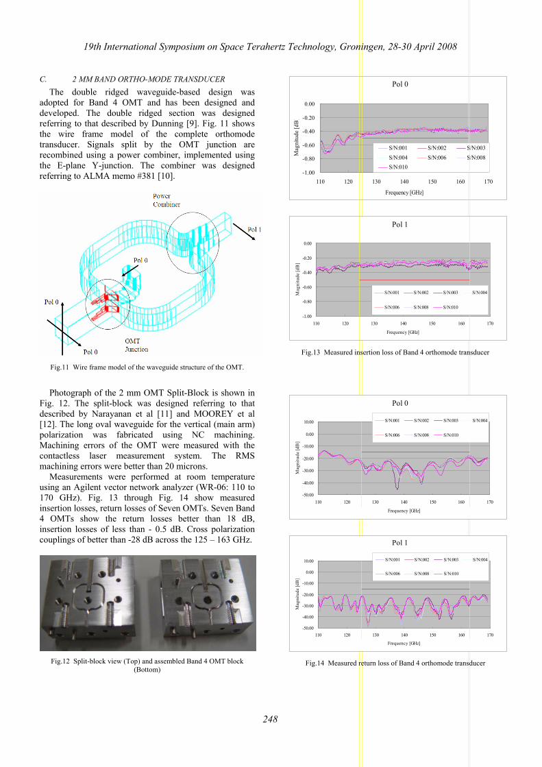
C. 2 MM BAND ORTHO-MODE TRANSDUCER The double ridged waveguide-based design was
adopted for Band 4 OMT and has been designed and developed. The double ridged section was designed referring to that described by Dunning [9]. Fig. 11 shows the wire frame model of the complete orthomode transducer. Signals split by the OMT junction are recombined using a power combiner, implemented using the E-plane Y-junction. The combiner was designed referring to ALMA memo #381 [10].
Fig.11 Wire frame model of the waveguide structure of the OMT.
Photograph of the 2 mm OMT Split-Block is shown in
Fig. 12. The split-block was designed referring to that described by Narayanan et al [11] and MOOREY et al [12]. The long oval waveguide for the vertical (main arm) polarization was fabricated using NC machining. Machining errors of the OMT were measured with the contactless laser measurement system. The RMS machining errors were better than 20 microns.
Measurements were performed at room temperature using an Agilent vector network analyzer (WR-06: 110 to 170 GHz). Fig. 13 through Fig. 14 show measured insertion losses, return losses of Seven OMTs. Seven Band 4 OMTs show the return losses better than 18 dB, insertion losses of less than - 0.5 dB. Cross polarization couplings of better than -28 dB across the 125 – 163 GHz.
Fig.12 Split-block view (Top) and assembled Band 4 OMT block
(Bottom)
Pol 0
-1.00
-0.80
-0.60
-0.40
-0.20
0.00
110 120 130 140 150 160 170
Frequency [GHz]
Mag
nitu
de [d
B]
S/N:001 S/N:002 S/N:003S/N:004 S/N:006 S/N:008S/N:010
Pol 1
-1.00
-0.80
-0.60
-0.40
-0.20
0.00
110 120 130 140 150 160 170
Frequency [GHz]
Mag
nitu
de [d
B]
S/N:001 S/N:002 S/N:003 S/N:004
S/N:006 S/N:008 S/N:010
Fig.13 Measured insertion loss of Band 4 orthomode transducer
Pol 0
-50.00
-40.00
-30.00
-20.00
-10.00
0.00
10.00
110 120 130 140 150 160 170
Frequency [GHz]
Mag
nitu
de [d
B]
S/N:001 S/N:002 S/N:003 S/N:004
S/N:006 S/N:008 S/N:010
Pol 1
-50.00
-40.00
-30.00
-20.00
-10.00
0.00
10.00
110 120 130 140 150 160 170
Frequency [GHz]
Mag
nitu
de [d
B]
S/N:001 S/N:002 S/N:003 S/N:004
S/N:006 S/N:008 S/N:010
Fig.14 Measured return loss of Band 4 orthomode transducer
19th International Symposium on Space Terahertz Technology, Groningen, 28-30 April 2008
248

IV. MEASUREMENTS OF THE PROTOTYPE CARTRIDGE The overall receiver noise temperatures of the Band 4
prototype cartridge averaged over the IF band of 4-8 GHz are plotted in Fig. 15. The noise temperatures were corrected for the contribution of the image sideband at IF center frequency 6 GHz. The noise performance includes the contribution of the vacuum window, IR filters, and IF amplifier chain. The measured single-sideband (SSB) receiver noise temperatures meet the ALMA noise temperature specification.
0
10
20
30
40
50
60
70
80
90
100
125 130 135 140 145 150 155 160 165Signal Frequency [GHz]
SSB
Noise
Tem
pera
ture
[K]
80% band spec (less than 51K) 20% band spec (less than 81K)Pol 0- USB Pol 0- LSBPol 1- USB Pol 1- LSB
Fig.15 SSB noise temperature of ALMA band 4 2SB mixer with averaging over the IF band of 4 – 8 GHz. Those noise temperature were corrected for the contribution of the image sideband at IF center frequency 6 GHz.
CONCLUSIONS In conclusion, we have been developing the ALMA
Band 4 cartridge receiver. To meet the technical specification, we have developed corrugated horn, OMT, 2SB SIS mixer, etc. The prototype cartridge results is promising that the Band 4 cartridge will meet the ALMA technical specification.
ACKNOWLEDGMENT Authors would like to thank Y. Kiuchi for fabricating
Band 4 SIS devices. We would also like to thank M. Sugimoto, Y. Sekimoto, Y. Uzawa, T. Noguchi, G. Fujii, S. Honma for their invaluable comments. We are also grateful to H. Ogawa and K. Kimura, and the entire people of the Advanced Technology Center and ALMA-J project office for their useful discussions and support.
REFERENCES [1] ALMA web site, http://www.alma.nrao.edu/. [2] M. Carter, A. Baryshev, M. Harman, B. Lazareff. S. Navarro, D.
John, G. Ediss C-Y. Tham, F. Tercero. R. Nesti, Y. Sekimoto, M. Matsunaga, H. Ogawa, “ALMA Front-end Optics report”, 2004.
[3] K. Kimura, H. Iwashita, S. Asayama, M. Sugimoto, G. Kikuchi, H. Ogawa, “Antenna Performance of a Directly Dug Corrugated Feedhorn for the 150-GHz Band”, IJIRMW, vol. 29, no. 8, pp 713-723, 2008
[4] E. Bryerton, K. Saini, M. Morgan, D. Thacker, “Development of Electronically Tuned Local Oscillators for ALMA”, 30th Int Conf on Infrared and Millimeter Waves, Sept 2005.
[5] S. Asayama, H. Ogawa, T. Noguchi, K. Suzuki, H. Andoh, A. Mizuno, “An Integrated Sideband-Separating SIS Mixer Based on Waveguide Split Block for 100 GHz Band with 4.0 - 8.0 GHz IF”, IJIRMW, vol. 25, no. 1, pp107-117, 2004
[6] S. C. Shi, T. Noguchi, and J. Inatani, “A 100 GHz fixed-tuned waveguide SIS mixer exhibiting broad bandwidth and very low noise temperature”, IEEE Trans. Appl. Superconduct., vol.7, no.4, pp.3850–3857, 1997.
[7] A. Kerr, S-K.Pan, J.E.Effland, “Sideband Calibration of Millimeter-Wave Receivers,” ALMA Memo #357, March 27, 2001.
[8] Nearfield Systems Inc, http://www.nearfield.com [9] A. Dunning, “Double Ridged Orthogonal Mode Transducer for
the 16-26GHz Microwave Band,” Proceedings of the Workshop on the Applications of Radio Science, 2002
[10] A. R. Kerr, “Elements for E-Plane Split-Block Waveguide Circuits,” ALMA Memo #381, July, 2001.
[11] G. Narayanan and N. Erickson, “Full-Waveguide Band Orthomode Transducer for the 3 mm and 1mm Bands,” Proceedings of the 14th International Symposium on Space Terahertz Technology, Tucson, Arizona, Apr. 2003, pp 508-512.
[12] G. G. Moorey, R. Bolton, A. Dunning, R. Gough, R, H. Kanoniuk, L. Reilly, "A 77-117 GHz cryogenically cooled receiver for radioastronomy". Workshop in Applications of Radio Science (WARS2006), Leura, NSW, 15-17 February, 2006.
19th International Symposium on Space Terahertz Technology, Groningen, 28-30 April 2008
249