Design and Construction Standards Volume 4 Water
198
Design and Construction Standards Volume 4 Water April 2021
Transcript of Design and Construction Standards Volume 4 Water
Design and Construction Standards
Volume 4
Water
April 2021

Page 2 of 198
Water Distribution & Transmission April 2021 Design and Construction Standards
Table of Contents Section 1 Design Standards ................................................................................................................................... 7
1.1 Definitions ....................................................................................................................................................................... 8 1.2 Acts, Bylaws And Standards ........................................................................................................................................... 8 1.3 Notice .............................................................................................................................................................................. 9 1.4 Records Management ..................................................................................................................................................... 9 1.5 Reference Standards .................................................................................................................................................... 12 1.6 Water Mains .................................................................................................................................................................. 15 1.7 Fire Hydrants ................................................................................................................................................................ 19 1.8 Valves ........................................................................................................................................................................... 19 1.9 Water Services .............................................................................................................................................................. 20 1.10 Manual Air Vents (MAV) ................................................................................................................................................ 20 1.11 Blow Offs ...................................................................................................................................................................... 21 1.12 Hydraulic Network Analysis (HNA) ................................................................................................................................ 21 1.13 Materials ....................................................................................................................................................................... 24 1.14 Utility Right Of Ways, Restrictive Covenants And Caveats ............................................................................................ 24 1.15 LID Construction Around Water Infrastructure .............................................................................................................. 25
Section 2 Water Mains ........................................................................................................................................... 28 2.1 General ......................................................................................................................................................................... 29 2.2 Materials ....................................................................................................................................................................... 31 2.3 Execution ...................................................................................................................................................................... 37
Section 3 Water Valves ......................................................................................................................................... 48 3.1 General ......................................................................................................................................................................... 49 3.2 Products ........................................................................................................................................................................ 50 3.3 Execution ...................................................................................................................................................................... 54
Section 4 Hydrants ................................................................................................................................................ 57 4.1 General ......................................................................................................................................................................... 58 4.2 Products ........................................................................................................................................................................ 58 4.3 Execution ...................................................................................................................................................................... 59 4.4 Protection During Adjacent Construction ...................................................................................................................... 60
Section 5 Water Services ...................................................................................................................................... 61 5.1 General ......................................................................................................................................................................... 62 5.2 Products ........................................................................................................................................................................ 63 5.3 Execution ...................................................................................................................................................................... 64
Section 6 Pipe Bedding ......................................................................................................................................... 68 6.1 General ......................................................................................................................................................................... 69 6.2 Products ........................................................................................................................................................................ 69 6.3 Execution ...................................................................................................................................................................... 69
Section 7 Cathodic Protection .............................................................................................................................. 71 7.1 General ......................................................................................................................................................................... 72 7.2 Products ........................................................................................................................................................................ 72 7.3 Execution ...................................................................................................................................................................... 73
Section 8 Guidelines for Acceptance Testing .................................................................................................... 76 8.1 Introduction And Background ........................................................................................................................................ 77 8.2 Guidelines for Water Main Flushing .............................................................................................................................. 77 8.3 Guidelines for Hydrostatic Testing ................................................................................................................................ 79 8.4 Procedure for Hydrostatic Testing................................................................................................................................. 80 8.5 Guidelines for Disinfection ............................................................................................................................................ 84 8.6 Guidelines for Sampling ............................................................................................................................................... 86 8.7 Dechlorination ............................................................................................................................................................... 87 8.8 Acceptance Testing Related Literature ..................................................................................................................... 90
Section 9 Guidelines for Boundary Valve Operation ......................................................................................... 91 9.1 Purpose ........................................................................................................................................................................ 92 9.2 Operating Rules ............................................................................................................................................................ 92
Section 10 PVC Tapping Guidelines .................................................................................................................. 93 10.1 General ......................................................................................................................................................................... 94 10.2 Resources ..................................................................................................................................................................... 94 10.3 Considerations .............................................................................................................................................................. 94

Page 3 of 198
Water Distribution & Transmission April 2021 Design and Construction Standards
10.4 Acceptance Guidelines for Tapping Valves and Sleeves (TVS) ................................................................................. 98
Section 11 Product Approval Procedures ......................................................................................................... 99 11.1 General ....................................................................................................................................................................... 100 11.2 Product Approval Procedures ..................................................................................................................................... 100 11.3 Approved Product List ................................................................................................................................................. 101
Section 12 Water Meters ................................................................................................................................... 114 12.1 General ....................................................................................................................................................................... 115 12.2 Materials ..................................................................................................................................................................... 115 12.3 Execution .................................................................................................................................................................... 116
Section 13 Concrete Requirements ................................................................................................................. 117 13.1 Scope .......................................................................................................................................................................... 118 13.2 Related Sections ......................................................................................................................................................... 118 13.3 Quality Control ............................................................................................................................................................ 118 13.4 Products ...................................................................................................................................................................... 118 13.5 Execution .................................................................................................................................................................... 119
Section 14 Detail Drawing Index ...................................................................................................................... 123 WA-002-001 ............................................................................................................................................................................ 126 WA-002-002 ............................................................................................................................................................................ 127 WA-002-003 ............................................................................................................................................................................ 128 WA-002-004 ............................................................................................................................................................................ 129 WA-002-005 ............................................................................................................................................................................ 130 WA-002-006 ............................................................................................................................................................................ 131 WA-002-007 ............................................................................................................................................................................ 132 WA-002-008a .......................................................................................................................................................................... 133 WA-002-008b .......................................................................................................................................................................... 134 WA-002-009 ............................................................................................................................................................................ 135 WA-002-010 ............................................................................................................................................................................ 136 WA-002-011 ............................................................................................................................................................................ 137 WA-002-012 ............................................................................................................................................................................ 138 WA-002-013 ............................................................................................................................................................................ 139 WA-002-014 ............................................................................................................................................................................ 140 WA-003-001 ............................................................................................................................................................................ 141 WA-003-002 ............................................................................................................................................................................ 142 WA-003-003 ............................................................................................................................................................................ 143 WA-003-004 ............................................................................................................................................................................ 144 WA-003-005 ............................................................................................................................................................................ 145 WA-003-006 ............................................................................................................................................................................ 146 WA-003-007 ............................................................................................................................................................................ 147 WA-003-008 ............................................................................................................................................................................ 148 WA-003-009 ............................................................................................................................................................................ 149 WA-003-010 ............................................................................................................................................................................ 150 WA-003-011 ............................................................................................................................................................................ 151 WA-003-012 ............................................................................................................................................................................ 152 WA-003-013 ............................................................................................................................................................................ 153 WA-003-014 ............................................................................................................................................................................ 154 WA-003-015 ............................................................................................................................................................................ 155 WA-003-016 ............................................................................................................................................................................ 156 WA-003-017 ............................................................................................................................................................................ 157 WA-003-018 ............................................................................................................................................................................ 158 WA-003-019 ............................................................................................................................................................................ 159 WA-003-020 ............................................................................................................................................................................ 160 WA-004-001 ............................................................................................................................................................................ 161 WA-004-002 ............................................................................................................................................................................ 162 WA-004-003 ............................................................................................................................................................................ 163 WA-004-004 ............................................................................................................................................................................ 164 WA-004-005 ............................................................................................................................................................................ 165 WA-005-001 ............................................................................................................................................................................ 166 WA-005-002 ............................................................................................................................................................................ 167 WA-005-003 ............................................................................................................................................................................ 168 WA-005-004 ............................................................................................................................................................................ 169

Page 4 of 198
Water Distribution & Transmission April 2021 Design and Construction Standards
WA-005-005 ............................................................................................................................................................................ 170 WA-005-006 ............................................................................................................................................................................ 171 WA-005-007 ............................................................................................................................................................................ 172 WA-005-008 ............................................................................................................................................................................ 173 WA-005-009 ............................................................................................................................................................................ 174 WA-005-010 ............................................................................................................................................................................ 175 WA-005-011a .......................................................................................................................................................................... 176 WA-005-011b .......................................................................................................................................................................... 177 WA-005-012 ............................................................................................................................................................................ 178 WA-005-013 ............................................................................................................................................................................ 179 WA-006-001 ............................................................................................................................................................................ 180 WA-007-001 ............................................................................................................................................................................ 181 WA-007-002 ............................................................................................................................................................................ 182 WA-007-003 ............................................................................................................................................................................ 183 WA-007-004 ............................................................................................................................................................................ 184 WA-007-005 ............................................................................................................................................................................ 185 WA-007-006 ............................................................................................................................................................................ 186 WA-007-007 ............................................................................................................................................................................ 187 WA-007-008 ............................................................................................................................................................................ 188 WA-007-009 ............................................................................................................................................................................ 189 WA-012-001 ............................................................................................................................................................................ 190 WA-012-002 ............................................................................................................................................................................ 191 WA-012-003 ............................................................................................................................................................................ 192 WA-012-004 ............................................................................................................................................................................ 193 WA-012-005 ............................................................................................................................................................................ 194 WA-012-006 ............................................................................................................................................................................ 195 WA-012-007 ............................................................................................................................................................................ 196 WA-012-008 ............................................................................................................................................................................ 197 WA-012-009 ............................................................................................................................................................................ 198

Page 5 of 198
Water Distribution & Transmission April 2021 Design and Construction Standards
List of Tables Table 1.1: Submissions required after water main construction ........................................................................................ 11
Table 1.2: Minimum water main depths ............................................................................................................................. 17
Table 1.3: Guidelines for Hydraulic Network Analysis ........................................................................................................ 25
Table 2.1: Minimum contact length for mandrel testing..................................................................................................... 44
Table 2.2: Required water quality parameters for new water mains ................................................................................. 46
Table 2.3: Operation and Maintenance Manual Requirements .......................................................................................... 47
Table 3.1: Acceptable depth of valve casing at finished grade .......................................................................................... 56
Table 4.1: Hydrant Connection Thread Requirements...................................................................................................... 59
Table 4.2: Hydrant paint colours ........................................................................................................................................ 60
Table 5.1: Material specifications for service rods ............................................................................................................ 65
Table 5.2: Minimum water service sizes ........................................................................................................................... 66
Table 6.1: Gradation limits for fine granular ...................................................................................................................... 70
Table 6.2: Gradation limits for coarse granular ................................................................................................................. 70
Table 6.3: Gradation limits for washed gravel ................................................................................................................... 70
Table 7.1: Requirements for anode lead wires in PVC conduit .......................................................................................... 75
Table 8.1: Number of ports required to achieve velocity for flushing ................................................................................. 79
Table 8.2: Chlorine required to produce 25 mg/L concentration in 100 m of water main ................................................. 86
Table 8.3: Chlorine Discharge Limits................................................................................................................................. 89
Table 8.4: Summary of Dechlorination Chemicals ............................................................................................................ 90
Table 10.1: Pipe tapping categories .................................................................................................................................. 96
Table 10.2: Pipe tapping equipment and procedures for Category 1 ................................................................................ 97
Table 10.3: Pipe tapping equipment and procedures for Categories 2 and 4 ................................................................... 98
Table 10.4: Categories 3 and 5 pipe tapping equipment and procedures ........................................................................ 99
Table 11.1: Main Stops - Select connections to suit Service Tubing material ................................................................ 102
Table 11.2: Service Saddles (Includes Tapped Repair Clamps) .................................................................................... 103
Table 11.3: Water Service Unions - Select connections to suit Service Tubing material ............................................... 103
Table 11.4: Polyvinyl Chloride (PVC) Service Pipe ......................................................................................................... 103
Table 11.5: Service Tubing .............................................................................................................................................. 104
Table 11.6: Curb Stops - Select connections to suit Service Tubing material ................................................................ 104
Table 11.7: Service Boxes Including Chairs and Rods ................................................................................................... 104
Table 11.8: CC Support Block ......................................................................................................................................... 104
Table 11.9: Polyvinyl Chloride (PVC) Water Pipe ........................................................................................................... 105
Table 11.10: Polyethylene (PE) Water Pipe* .................................................................................................................. 105
Table 11.11: Concrete Steel Cylinder Water Pipe* ......................................................................................................... 105
Table 11.12: Ductile Iron Water Pipe* ............................................................................................................................. 105
Table 11.13: Lubricants ................................................................................................................................................... 105
Table 11.14: Water Main Tracing .................................................................................................................................... 106
Table 11.15: Couplings (PVC) ......................................................................................................................................... 106
Table 11.16: Bolted Sleeve Couplings and Adaptors ...................................................................................................... 107
Table 11.17: Water Main Fittings..................................................................................................................................... 108
Table 11.18: Tapping Sleeves ......................................................................................................................................... 109
Table 11.19: Expansion Joints ........................................................................................................................................ 109
Table 11.20: Butterfly Valves .......................................................................................................................................... 109
Table 11.21: Gate Valves ................................................................................................................................................ 109
Table 11.22: Check Valves .............................................................................................................................................. 110
Table 11.23: Automatic Air Valves .................................................................................................................................. 110
Table 11.24: Manual Air Valves....................................................................................................................................... 110
Table 11.25: Pressure Reducing Valves ......................................................................................................................... 110
Table 11.26: Flow Control Valves.................................................................................................................................... 110

Page 6 of 198
Water Distribution & Transmission April 2021 Design and Construction Standards
Table 11.27: Valve Casings and Middle Extensions ........................................................................................................ 111
Table 11.28: Fire Hydrants .............................................................................................................................................. 111
Table 11.29: Epoxy Coatings and Linings ....................................................................................................................... 111
Table 11.30: Plant Coatings ............................................................................................................................................ 111
Table 11.31: Tape Coatings (Cold Applied) .................................................................................................................... 112
Table 11.32: Heat-Shrinkable Sleeves (Exterior Protection – Joints/Flanges/Fittings) ................................................... 112
Table 11.33: Cathodic Protection Weld Protection Materials .......................................................................................... 112
Table 11.34: Cathodic Protection Splice Protection Materials ........................................................................................ 113
Table 11.35: Manhole Frames and Covers ..................................................................................................................... 113
Table 11.36: Alarms (Hatch) ............................................................................................................................................ 113
Table 11.37: Insulation .................................................................................................................................................... 113
Table 11.38: Pipe Casing Spacers .................................................................................................................................. 114
List of Figures Figure 1.1 Areas in Edmonton where water mains are generally considered to have a greater risk of freezing due to soil
conditions ............................................................................................................................................................................ 17
Figure 8.1 Estimating discharge from a hydrant or blowoff ................................................................................................ 80
Figure 8.2 Apparatus for Hydrostatic Testing .................................................................................................................... 81

Volume 4 Water
Section 1 Design Standards
April 2021
Page 8 of 198
Water Distribution & Transmission April 2021 Section 1: Design Standards
1.1 DEFINITIONS
1.1.1 EPCOR, EPCOR Water Services: The water utility company that services the City of Edmonton.
1.1.2 Engineer: The person for the time being designated by the Senior Vice President, EPCOR Water Services, to represent EPCOR during the course of the work.
1.1.3 Inspector: The person for the time being designated by the Senior Vice President EPCOR Water Services, to inspect the works on behalf of EPCOR.
1.1.4 Consultant: As defined in the City of Edmonton Design and Construction Standards Volume 1: General.
1.1.5 Developer: As defined in the City of Edmonton Design and Construction Standards Volume 1: General.
1.2 ACTS, BYLAWS AND STANDARDS
1.2.1 Where acts, bylaws and standards are referred to, they shall be current, amended and updated issues of such.
1.2.2 EPCOR will notify Alberta Environment and Parks of the proposed construction as required by the Alberta Environmental Protection and Enhancement Act.
1.2.3 It shall be a responsibility of the Consultant undertaking a development project to be aware of the statutory requirements governing such works and for compliance with those requirements. The listing provided below is for guidance. Other statutory instruments, not included here, may be applicable. All work performed on the water distribution system shall meet the minimum requirements as set out in:
1.2.3.1 Fisheries Act of Canada, pertaining to the prevention of discharge of chlorinated water and response (s.34 to 43)
1.2.3.2 The Standards and Guidelines for Municipal Water Supply, Wastewater and Storm Drainage Facilities - Alberta
Environment and Sustainable Resources Development (Alberta Environment and Parks as of 2015)
1.2.3.3 The Province of Alberta, Environmental Protection and Enhancement Act
1.2.3.4 The City of Edmonton, Water Services and Wastewater Treatment EPCOR Bylaw 15816
1.2.3.5 The City of Edmonton, Drainage Bylaw 16200
1.2.3.6 National Plumbing Code of Canada
1.2.3.7 Alberta Building Code, pertaining to access to fire hydrants (Part 3)
1.2.4 It shall be a responsibility of the Consultant undertaking a development project to be aware of all the requirements of these Design and Construction Standards in their entirety and for compliance with those requirements. Some aspects of water design and construction require compliance with the requirements of other Volumes and Sections of these Design and Construction Standards. The listing provided below is for guidance. Other requirements, not included here, may be applicable. All work performed on the water distribution system shall meet the minimum requirements as set out in:
1.2.4.1 Volume 1: General
1.2.4.2 Volume 1: Table of Offsets
1.2.4.3 Volume 2: Roadways, Section 7.11 - Fillcrete
1.2.4.4 Volume 2: Roadways, Section 3.1 - Trench Backfill
1.2.4.5 Volume 2: Roadways, Section 3.2 - Utility Cut Restoration
1.2.4.6 Volume 2: Roadways, Section 7.12 - Reinforcing Steel
1.2.4.7 Volume 2: Roadways, Drawings 1020 to 1025 - Transverse Cut Restoration
1.2.4.8 Volume 2: Roadways, Drawings 2120-2730 - Cross Sections
1.2.4.9 Volume 2: Roadways, Drawing 7980 to 7981 - Backfill Details with Valve Raised to Grade
1.2.4.10 Volume 3: Drainage, Section 02445 - Bored Undercrossings
1.2.4.11 Volume 3: Drainage, Section 02446 - Horizontal Directional Drilling
1.2.4.12 Volume 3: Drainage, Section 02559 - Factory Applied Pipe Insulation
1.2.4.13 Volume 3: Drainage, Section 02631 - Manholes and Catch Basins
1.2.4.14 Volume 3: Drainage, Section 03310 - Concrete for Water and Drainage Structures
1.2.4.15 Volume 3: Drainage, Drawings 7013, 7014, 7034 - Standard 1200 Manhole
1.2.4.16 Volume 3: Drainage, Drawing 7043A/B - Type 6 Standard Manhole
1.2.4.17 Volume 3: Drainage, Drawing 7063 - Standard Riser Connections

Page 9 of 198
Water Distribution & Transmission April 2021 Section 1: Design Standards
1.3 NOTICE
1.3.1 48 hours written notice shall be given to the Engineer or Inspector before commencement of work, or changes in work schedules or working, to facilitate coordination with EPCOR or City inspection staff.
1.3.2 Valves 300 mm in diameter and smaller must be operated under the supervision of an EPCOR Water Inspector. The EPCOR Water Inspector must be contacted a minimum of 48 hours in advance.
1.3.3 Valves 350 mm in diameter and larger must be operated by EPCOR Water Operations Staff. The EPCOR Water Inspector must be contacted a minimum of 72 hours in advance to make arrangement for the operation of these valves. Additional notice may be required on a case by case basis at the discretion of EPCOR Water Services.
1.4 RECORDS MANAGEMENT
1.4.1 All drawings submitted for approval must be signed and sealed by a registered professional engineer indicating their proposals for sizes and routes of water distribution and transmission mains, locations of control valves and details of valve chambers, thrust blocks and other appurtenances. The drawings shall conform to the requirements of Volume 1 of these Standards and shall be subject to the approval of the Engineer.
1.4.1.1 Registered professional technologists may sign and seal drawing submissions wherein water mains are less than
or equal to 300 mm in diameter and the design falls within their approved scope of practice.
1.4.2 In addition to the requirements in Volume 1 – General, all engineering drawing submissions must include the following:
1.4.2.1 A drawing that shows the approved water network from the hydraulic network analysis (HNA) submitted at
Neighbourhood Structure Plan (NSP) indicating mains as existing, proposed and or future and indicating pipe
sizes. Also include on this drawing a list of quantities for the stage being submitted in accordance with the
submitted drawings. Quantities should include the length of main by size, number of hydrants, number of flush
points and number of services by size.
1.4.2.2 A copy of the geotechnical report with any deviation from minimum soil bearing capacities of 72 kPa and any
water table readings that result in the natural water table being above the hydrant boot for any areas within the
stage being submitted clearly identified within the report.
1.4.2.3 A copy of the calculations utilized to determine the sizing of water main thrust blocks, if modified thrust blocks are
required as part of the design.
1.4.2.4 A copy of the calculations utilized to determine the restraint length for water main joints, if restrained joints are
required as part of the design.
1.4.2.5 A copy of the thermal expansion and contraction calculations for fully restrained, fused PVC, or directionally
drilled water mains.
1.4.2.6 Acceptance testing plans as described in Sections 1.4.7 – 1.4.9.
1.4.3 Where the proposals include crossings (e.g. railways, high-pressure pipelines. etc.) the individual(s) responsible for the proposal shall also be fully responsible for:
1.4.3.1 The preparation and submission of drawings to the owners and proper authorities;
1.4.3.2 Obtaining the necessary permission or permits to enter upon, cross over, or construct under any crossing;
1.4.3.3 Any work, extra costs, damage claims, or insurance costs related to any of the crossings; and
1.4.3.4 The submission of documentary evidence that such permits have been obtained prior to the approval of the
drawings.
1.4.4 Should the Engineer not approve any part of the drawings or proposals, they will be returned for revision to the satisfaction of the Engineer and the period from return to re-submission of such drawings or proposals shall be deemed to be additional to that specified for first submission.
1.4.5 A drawing package containing the following must be submitted and received by EPCOR Water Services a minimum of three business days prior to holding the pre-construction meeting:
1.4.5.1 One (1) full-sized print in accordance with the approved detailed engineering drawing set;
1.4.5.2 One (1) full-sized print of the overall Water, Storm, and Sanitary plan;
1.4.5.3 A digital submission of the detailed engineering drawing set in a portable document format (.pdf) file must be
submitted by e-mail to [email protected] or on compact disk. The digital submission is to be named "WP-
[email protected]", where “@” is the phase letter. Each phase requires a separate submission;

Page 10 of 198 Water Distribution & Transmission April 2021 Section 1: Design Standards
1.4.5.4 A digital submission of the overall Water, Storm, and Sanitary plan complete with base map must be submitted by
e-mail to [email protected] or on compact disk. The digital submission must include be a MicroStation
compatible design (.DGN) file of the infrastructure. The .DGN file must be recorded in NAD 83 3TM coordinates.
Digital submissions must be in the format of “[email protected]”, where “@” is the phase letter. Each
phase requires a separate submission;
1.4.5.5 A digital submission of the overall Water, Storm, and Sanitary plan complete with base map must be submitted by
e-mail to [email protected] or on compact disk. The digital submission must be a portable document format
(.PDF) file. Digital submissions must be in the format of “[email protected]”, where “@” is the phase
letter. Each phase requires a separate submission; and
1.4.5.6 EPCOR Water Project Numbers (e.g. WP-XXXXX@-XXXX, where “@” is the phase letter and each phase
requires a separate submission) will be provided as part of the engineering drawing approval process.
1.4.6 The submissions described in the remainder of this section take place after the completion and approval of the design. The individual(s) responsible for the proposal must ensure that these submissions are completed. These requirements are listed here because the Consultant who prepared the design will normally provide these services.
1.4.6.1 Within six months after the C.C.C. inspection, revised drawings containing any changes made to the approved
design shall be submitted to EPCOR for review. The as-built data that differs from the design shall be clearly
identified on either an electronic or paper copy of the original design. The drawings must identify the name of the
Engineer that approved the design along with the date that the drawing was approved. Drafting, notes and
dimensions shall comply with Section 1.5.3. Any revisions shall be shown on all affected drawings.
1.4.6.2 Final as-built drawings shall be submitted on velum or mylar within 30 days of receipt of EPCOR’s response to
the revision drawings submission. Design data shall be erased on the original and replaced with as-built data in
ink. The date of construction completion is to be shown by a note on each plan profile drawing. All quantities,
lengths and sizes of water mains, appurtenances and fittings shall be tabulated on the as-built drawings. All as-
built sewer information shall also be shown. Final as-built drawings shall comply with Section 1.5.3. As-built water
facility reports are available at www.epcor.com. Additional submission requirements, media and formats, such as
digital, are detailed in a letter for each project.
1.4.6.2.1 Service details for all services installed as part of the project must be updated with as-built coordinates
and alignments prior to C.C.C. The details must show the main stop, curb stop, end of pipe, and any
pipe deviations. The details must be submitted to [email protected] in MicroStation .dgn format with
the service information provided in the NAD83 3TM coordinate system. The file must include all property
lines for reference. This is in addition to the service reports submitted to IWASS. Please ensure the file
is named “WP-XXXXX@- ServiceDtlAB.dgn”, where “@” is the phase letter. Each phase requires a
separate submission. Service materials and sizes must be provided in a table on final as-built drawings.
1.4.6.3 The following documentation shall be submitted by the deadlines as shown in Table 1.1 below.
Table 1.1: Submissions required after water main construction
ITEM DEADLINE
Coupon test results 2 weeks prior to hydrostatic testing
Fused PVC test reports 2 weeks prior to hydrostatic testing
Pull data for directional drilling 2 weeks prior to hydrostatic testing
Weld Reports 2 weeks prior to hydrostatic testing
X-Ray/Radiographic records 2 weeks prior to hydrostatic testing
Flushing Report Prior to C.C.C. inspection.
Hydrostatic Test Results Prior to C.C.C. inspection.
Pressure Gauge Calibration Results Prior to C.C.C. inspection.
Chlorine Residual Test Results Prior to C.C.C. inspection.
Chlorine Test Kit Calibration Results Prior to C.C.C. inspection.
Bacteriological Test Results Prior to C.C.C. inspection.
Taste and Odour Test Results Prior to C.C.C. inspection.
Thrust Block Report and Concrete Test Results Prior to C.C.C. signing by Engineer.
URW Documentation & Crossing Permits Prior to C.C.C. signing by Engineer.
As-Built Quantities and Costs Report Prior to C.C.C. signing by Engineer.
Hydrant Flow Test Requests Prior to C.C.C. signing by Engineer.
As-Built Drawings (for EPCOR review) Prior to C.C.C. signing by Engineer.
Acceptance Letter from iWASS Prior to F.A.C. signing by Engineer.
Water Main Grade Sheets Prior to F.A.C. signing by Engineer.
Final As-Built Drawings Prior to F.A.C. signing by Engineer.

Page 11 of 198 Water Distribution & Transmission April 2021 Section 1: Design Standards
1.4.7 The following outlines the submissions, reporting and record keeping requirements for water main flushing:
1.4.7.1 The Consultant must submit a Flushing Plan according to Section 1.4.2.6. The plan shall:
1.4.7.1.1 Include a written flushing procedure;
1.4.7.1.2 Include a spreadsheet indicating:
1.4.7.1.2.1 Order of flushing runs;
1.4.7.1.2.2 Length of flushing runs;
1.4.7.1.2.3 Water supply (source valve);
1.4.7.1.2.4 Discharge hydrant(s);
1.4.7.1.2.5 Valve statuses for all valves on each flushing run;
1.4.7.1.2.6 Pipe properties for each flushing run;
1.4.7.1.2.7 Required discharge volume (to achieve five times the volume of the flushed segment);
1.4.7.1.2.8 Minimum flow velocity for the size of the water main;
1.4.7.1.2.9 Minimum flow rate to achieve the velocity;
1.4.7.1.2.10 Type and size of ports to discharge the water;
1.4.7.1.2.11 Number of ports;
1.4.7.1.2.12 Estimated flow rate; and
1.4.7.1.2.13 Required flush time.
1.4.7.1.3 Include a drawing for each segment of flushing indicating the following:
1.4.7.1.3.1 Water supply (source valve);
1.4.7.1.3.2 Current flush;
1.4.7.1.3.3 Completed flush;
1.4.7.1.3.4 Opened Valve;
1.4.7.1.3.5 Closed Valve(s);
1.4.7.1.3.6 Discharge hydrant(s); and
1.4.7.1.3.7 Legend clearly indicating the symbology on the drawing.
1.4.7.1.4 Be signed and sealed by a Professional Engineer; and
1.4.7.1.5 Be submitted for approval to [email protected].
1.4.7.2 A copy of the approved Flushing Plan must be on site during flushing activities.
1.4.7.3 A record of all flushing activities for the project must be recorded using the Flushing Report form provided on
EPCOR’s website.
1.4.8 The following outlines the submissions, reporting and record keeping requirements for hydrostatic testing:
1.4.8.1 The Consultant must submit a Hydrostatic Testing Plan according to Section 1.4.2.6. The plan shall:
1.4.8.1.1 Include drawing for each segment of hydrostatic testing indicating:
1.4.8.1.1.1 The segment to be tested;
1.4.8.1.1.2 Top-up source(s);
1.4.8.1.1.3 Air relief location(s);
1.4.8.1.1.4 The location of the pump, testing equipment and connections to the new infrastructure;
1.4.8.1.1.5 North arrow;
1.4.8.1.1.6 Street name(s);
1.4.8.1.1.7 Appurtenance(s); and
1.4.8.1.1.8 Appurtenance number(s).
1.4.8.1.2 Be signed and sealed by a Professional Engineer; and
1.4.8.1.3 Be submitted for approval to [email protected].
1.4.8.2 A copy of the approved Hydrostatic Testing Plan must be on site during flushing activities.
1.4.8.3 The Consultant must submit the following documents (if applicable) at least 2 weeks prior to hydrostatic;
testing:
1.4.8.3.1 Weld reports;
1.4.8.3.2 X-ray/radiographic records;
1.4.8.3.3 Coupon test results;
Page 12 of 198 Water Distribution & Transmission April 2021 Section 1: Design Standards
1.4.8.3.4 Fused PVC test reports; and
1.4.8.3.5 Pull data for directional drilling.
1.4.8.4 The hydrostatic testing results must be recorded at the testing location using the EPCOR standard form
provided on EPCOR’s website.
1.4.8.5 The form must be certified by the Consultant and the Contractor before submitting to the EPCOR Inspector.
1.4.8.6 Pressure gauge calibration results must be submitted as an attachment to the form.
1.4.9 The following outlines the submissions, reporting and record keeping requirements for disinfection, bacteriological and taste and odour testing:
1.4.9.1 The Consultant must submit a Disinfection, Bacteriological and Taste and Odour Plan according to
Section 1.4.2.6. The plan shall:
1.4.9.1.1 Include a written disinfection procedure indicating the:
1.4.9.1.1.1 Chlorine application method;
1.4.9.1.1.2 Chlorine chemical to be used;
1.4.9.1.1.3 Number of samples required;
1.4.9.1.1.4 Discharge location;
1.4.9.1.1.5 Dechlorination method; and
1.4.9.1.1.6 Neutralizing chemical to be used.
1.4.9.1.2 Include a sketch indicating:
1.4.9.1.2.1 The chlorine injection point;
1.4.9.1.2.2 The sampling point(s);
1.4.9.1.2.3 The primary discharge location; and
1.4.9.1.2.4 All valve statuses.
1.4.9.1.3 Be signed and sealed by a Professional Engineer; and
1.4.9.1.4 Be submitted for approval to [email protected].
1.4.9.2 A copy of the approved Disinfection, Bacteriological and Taste and Odour Plan must be on site during flushing
activities.
1.4.9.3 The chlorination and bacteriological test results for the section of water main being tested must be recorded using
the form provided on EPCOR’s website.
1.4.9.4 The form must be completed and stamped by a qualified engineering professional responsible for
disinfection and bacteriological sampling.
1.4.9.5 Chlorine test kit calibration results must be submitted as an attachment to the form.
1.5 REFERENCE STANDARDS
1.5.1 ORGANIZATIONS ISSUING STANDARDS INCLUDE:
1.5.1.1 Alberta Environment and Parks (AEP)
1.5.1.2 Alberta Government
1.5.1.3 Alberta Health Services (AHS)
1.5.1.4 American Society for Testing and Materials (ASTM)
1.5.1.5 American National Standards Institute (ANSI)
1.5.1.6 American Petroleum Institute (API)
1.5.1.7 American Water Works Association (AWWA)
1.5.1.8 Canadian Standards Association (CSA)
1.5.1.9 National Association of Corrosion Engineers (NACE)
1.5.1.10 National Sanitation Foundation (NSF)
1.5.1.11 Underwriters Laboratories of Canada (ULC)

Page 13 of 198 Water Distribution & Transmission April 2021 Section 1: Design Standards
1.5.2 TECHNICAL STANDARDS AND GUIDELINES REFERENCED:
1.5.2.1 Unless otherwise designated, all specification and standard references refer to the latest edition. The listing
provided below is for guidance. Other standards, not included here, may be applicable, and other references may
be of use to consultants and contractors. Water mains and appurtenances shall conform to applicable standards,
including the following:
1.5.2.1.1 Alberta Occupational Health and Safety Code
1.5.2.1.2 AWWA B300 – Hypochlorites
1.5.2.1.3 AWWA C104 – Cement Mortar Lining for Ductile-Iron Pipe and Fittings
1.5.2.1.4 AWWA C105 – Polyethylene Encasement for Ductile Iron Pipe Systems
1.5.2.1.5 AWWA C110 – Ductile-Iron and Gray-Iron Fittings
1.5.2.1.6 AWWA C111 – Rubber-Gasket Joints for Ductile-Iron Pressure Pipe and Fittings
1.5.2.1.7 AWWA C151 – Ductile-Iron Pipe, Centrifugally Cast
1.5.2.1.8 AWWA C200 – Steel Water Pipe—6 In. (150 mm) and Larger
1.5.2.1.9 AWWA C206 – Field Welding of Steel Water Pipe
1.5.2.1.10 AWWA C207 – Steel Pipe Flanges for Waterworks Service—Sizes 4 In. Through 144 In. (100 mm
Through 3,600 mm)
1.5.2.1.11 AWWA C208 – Dimensions for Fabricated Steel Water Pipe Fittings
1.5.2.1.12 AWWA C209 – Cold Applied Tape Coatings for the Exterior of Special Sections, Connections, and
Fittings for Steel Water Pipelines
1.5.2.1.13 AWWA C210 – Liquid Epoxy Coating Systems for the Interior and Exterior of Steel Water Pipelines
1.5.2.1.14 AWWA C213 – Fusion-Bonded Epoxy Coating for the Interior and Exterior of Steel Water Pipelines
1.5.2.1.15 AWWA C214 – Tape Coating Systems for Exterior of Steel Water Pipelines
1.5.2.1.16 AWWA C215 – Extruded Polyolefin Coatings for the Exterior of Steel Water Pipelines
1.5.2.1.17 AWWA C216 – Heat Shrinkable Cross-Linked Polyolefin Coatings for the Exterior of Special Sections,
Connections, and Fittings for Steel Water Pipelines
1.5.2.1.18 AWWA C217 – Petrolatum and Petroleum Wax Tape Coatings for the Exterior of Connections and
Fittings for Steel Water Pipelines
1.5.2.1.19 AWWA C219 – Bolted, Sleeve-Type Couplings for Plain-End Pipe
1.5.2.1.20 AWWA C223 – Fabricated Steel and Stainless Steel Tapping Sleeves
1.5.2.1.21 AWWA C301 – Pre-stressed Concrete Pressure Pipe, Steel-Cylinder type
1.5.2.1.22 AWWA C303 – Concrete Pressure Pipe, Bar-Wrapped, Steel-Cylinder Type
1.5.2.1.23 AWWA C304 –Design of Prestressed Concrete Cylinder Pipe
1.5.2.1.24 AWWA C500 – Metal-Seated Gate Valves for Water Supply Service
1.5.2.1.25 AWWA C502 – Dry-Barrel Fire Hydrants
1.5.2.1.26 AWWA C504 – Rubber-Seated Butterfly Valves, 3 In. (75 mm) Through 72 In. (1,800 mm)
1.5.2.1.27 AWWA C508 – Swing-Check Valves for Waterworks Service, 2-In. Through 24-In. (50-mm Through 600-
mm) NPS
1.5.2.1.28 AWWA C509 – Resilient-Seated Gate Valves for Water Supply Service
1.5.2.1.29 AWWA C510 – Double Check Valve Backflow Prevention Assembly
1.5.2.1.30 AWWA C511 – Reduced-Pressure Principle Backflow Prevention Assembly
1.5.2.1.31 AWWA C512 – Air-Release, Air/Vacuum, and Combination Air Valves for Waterworks Service
1.5.2.1.32 AWWA C515 – Reduced-Wall, Resilient-Seated Gate Valves for Water Supply Service
1.5.2.1.33 AWWA C550 – Protective Interior Coatings for Valves and Hydrants
1.5.2.1.34 AWWA C600 – Installation of Ductile-Iron Mains and Their Appurtenances
1.5.2.1.35 AWWA C605 – Underground Installation of Polyvinyl Chloride (PVC) Pressure Pipe and Fittings for
Water
1.5.2.1.36 AWWA C606 – Grooved and Shouldered Joints
1.5.2.1.37 AWWA C651 – Disinfecting Water Mains
1.5.2.1.38 AWWA C700 – Cold-Water Meters – Displacement Type, Bronze Main Case
Page 14 of 198 Water Distribution & Transmission April 2021 Section 1: Design Standards
1.5.2.1.39 AWWA C701 – Cold-Water Meters – Turbine Type, for Customer Service
1.5.2.1.40 AWWA C710 – Cold-Water Meters – Displacement Type, Plastic Main Case
1.5.2.1.41 AWWA C800 – Underground Service Line Valves and Fittings
1.5.2.1.42 AWWA C900 – Polyvinyl Chloride (PVC) Pressure Pipe and Fabricated Fittings, 4 In. Through 12 I n.
(100 mm through 300 mm), for Water Transmission and Distribution
1.5.2.1.43 AWWA C901 – Polyethylene (PE) Pressure Pipe and Tubing, ½ In. (13 mm) Through 3 In. (76 mm), for
Water Service
1.5.2.1.44 AWWA C903 – Polyethylene—Aluminum—Polyethylene & Cross-linked Polyethylene—Aluminum—
Cross-Linked Polyethylene Composite Pressure Pipes, ½ In. (12 mm) Through 2 In. (50 mm), for Water
Service
1.5.2.1.45 AWWA C905 – Polyvinyl Chloride (PVC) Pressure Pipe and Fabricated Fittings, 14 In. Through 48 In.
(350 mm through 1,200 mm)
1.5.2.1.46 AWWA C906 – Polyethylene (PE) Pressure Pipe and Fittings, 4 In. (100 mm) Through 63 In. (1,600
mm), for Water Distribution and Transmission
1.5.2.1.47 AWWA C907 – Injection-Molded Polyvinyl Chloride (PVC) Pressure Fittings, 4 In. Through 12 In. (100
mm through 300 mm), for Water Distribution
1.5.2.1.48 AWWA M9 – Concrete Pressure Pipe
1.5.2.1.49 AWWA M11 – Steel Pipe - A Guide for Design and Installation
1.5.2.1.50 AWWA M17 – Installation, Field Testing and Maintenance of Fire Hydrants
1.5.2.1.51 AWWA M22 – Sizing Water Service Lines and Meters
1.5.2.1.52 AWWA M23 – PVC Pipe—Design and Installation
1.5.2.1.53 AWWA M32 – Computer Modeling of Water Distribution Systems
1.5.2.1.54 AWWA M55 – PE Pipe—Design and Installation
1.5.2.1.55 CSA A23.1 – Concrete materials and methods of concrete construction
1.5.2.1.56 CSA A23.2 – Test methods and standard practices for concrete
1.5.2.1.57 CSA B64 – Selection and installation of backflow preventers
1.5.2.1.58 CSA B137.0 – Definitions, General Requirements and Methods of Testing for Thermoplastic Pressure
Piping
1.5.2.1.59 CSA B137.1 – Polyethylene (PE) Pipe, Tubing and Fittings for Cold-Water Pressure Services
1.5.2.1.60 CSA B137.2 – Polyvinylchloride (PVC) Injection-Moulded Gasketed Fittings for Pressure Applications
1.5.2.1.61 CSA B137.3 – Rigid Polyvinylchloride (PVC) Pipe and Fittings for Pressure Applications
1.5.2.1.62 CSA B137.5 – Crosslinked Polyethylene (PEX) Tubing Systems for Pressure Applications
1.5.2.1.63 CSA C22.2 No. 38 – Thermoset Insulated Wires and Cables
1.5.2.1.64 CSA C22.3 No.4 – Control of Electrochemical Corrosion of Underground Metallic Structures
1.5.2.1.65 CSA C22.3 No.6 – Principles and Practices of Electrical Coordination between Pipelines and Electric
Supply Lines
1.5.2.1.66 CSA W47.1 – Certification of Companies for Fusion Welding of Steel
1.5.2.1.67 CSA Z662 – Oil and Gas Pipeline Systems
1.5.2.1.68 API Standard 1104 – Welding of Pipelines and Related Facilities
1.5.2.1.69 ASTM A48 – Standard Specification for Gray Iron Castings
1.5.2.1.70 ASTM A105 – Standard Specification for Carbon Steel Forgings for Piping Applications
1.5.2.1.71 ASTM A307 – Standard Specification for Carbon Steel Bolts and Studs, 60 000 PSI Tensile Strength
1.5.2.1.72 ASTM A536 – Standard Specification for Ductile Iron Castings
1.5.2.1.73 ASTM B62 – Standard Specification for Composition Bronze or Ounce Metal Castings
1.5.2.1.74 ASTM B88 – Standard Specification for Seamless Copper Water Tube
1.5.2.1.75 ASTM B418 – Standard Specification for Cast and Wrought Galvanic Zinc Anodes
1.5.2.1.76 ASTM B843 – Standard Specification for Magnesium Alloy Anodes for Cathodic Protection
1.5.2.1.77 ASTM C33 – Standard Specification for Concrete Aggregates
1.5.2.1.78 ASTM C150 – Standard Specification for Portland Cement

Page 15 of 198 Water Distribution & Transmission April 2021 Section 1: Design Standards
1.5.2.1.79 ASTM D3034 – Standard Specification for Type PSM Poly(Vinyl Chloride) (PVC) Sewer Pipe and
Fittings
1.5.2.1.80 ASTM F477 – Standard Specification for Elastomeric Seals (Gaskets) for Joining Plastic Pipe
1.5.2.1.81 ASTM F1962 – Standard Guide for Maxi-Horizontal Directional Drilling for Placement of Polyethylene
Pipe or Conduit Under Obstacles, Including River Crossings
1.5.2.1.82 ASTM F2620 – Standard Practice for Heat Fusion Joining of Polyethylene Pipe and Fittings
1.5.2.1.83 ASTM G57 – Standard Test Method for Field Measurement of Soil Resistivity Using the Wenner Four-
Electrode Method
1.5.2.1.84 ASTM G97 – Standard Test Method for Laboratory Evaluation of Magnesium Sacrificial Anode Test
Specimens for Underground Applications
1.5.2.1.85 Canadian Electrical Code (CEC) C22.1 – Safety Standard for Electrical Installations, Parts 1 and 2
1.5.2.1.86 CSA-A3000
1.5.2.1.87 NACE SP0169-2013 - Control of External Corrosion on Underground or Submerged Metallic Piping
Systems
1.5.2.1.88 National Sanitation Foundation (NSF) Standard 14 – Plastics Piping System Components & Related
Materials
1.5.2.1.89 National Sanitation Foundation (NSF) Standard 61 – Drinking Water System Components - Health
Effects
1.5.3 DRAFTING GUIDELINES
1.5.3.1 All streets and avenues shall be identified according to the name or number shown on the registered plan of the
subdivision. Alleys shown on drawings where the adjacent street or avenue is not shown, shall be identified as
the alley east or west of a street, or the alley north or south of an avenue; e. g. LW 115 Street, LN 145 Avenue.
1.5.3.2 The position of all hydrants, valves, plugs, bends, crosses, tees, reducers and other fittings or appurtenances
shall be noted and dimensioned in two directions from the property line(s). Co-ordinates given in NAD83 3TM will
be accepted in place of dimensions.
1.5.3.3 Water main annotation shall include pipe size, pipe material, manufacturer and dimension ratio (DR).
1.5.3.4 A detailed description of all fittings must be indicated, for example: 200 mm x 150 mm reducer 200 mm x 22.5°
bend. Tees and crosses must be indicated with a minimum of 2 sizes as shown in the following examples:
1.5.3.4.1 For a 250 mm x 200 mm Tee the run is 250 mm and the branch is 200 mm in diameter.
1.5.3.4.2 For a 250 mm x 200 mm Cross the run is 250 mm and the branches are 200 mm in diameter.
1.5.3.5 If the sizes of the through branches differ, each of the four branch sizes must be shown.
1.5.3.6 All applicable Standard Details for water mains and appurtenances are shown or listed on the drawings.
1.5.3.7 All boundary valves must be clearly identified on the engineering drawings.
1.5.3.8 For any submissions that are proposed to be staged: ensure that staging boundaries, interim boundary valves,
and interim plugs are clearly identified on the engineering drawings.
1.5.3.9 Hydrant circles at 90 m or 150 m in diameter must be shown on overall utility plans. Circle diameter is to be
appropriate for adjacent zoning. In locations where circles of different sizes may be required due to mixed zoning
show both circles.
1.6 WATER MAINS
1.6.1 LOCATION
1.6.1.1 When gas, power, and telecommunications utilities are installed in a single trench (four party trenching) primary
power may be installed on the same side of the road as the water main.
1.6.1.2 Parks furniture must be installed in a manner to prevent conflicts with operations and maintenance of hydrants
and hydrant control valves.
1.6.1.3 Where a tree or shrub bed is installed within 5.0 m of a valve, hydrant, or curb cock, dimensions must be
provided as part of the engineering drawing submission package.
1.6.2 DEPTH
1.6.2.1 Pipe grades shall be shown on the engineering drawings. Table 1.2 shows the minimum depth of water main
invert below the curb top, excluding those areas considered by the Engineer to be of greater risk of freezing
based due to soil conditions.

Page 16 of 198 Water Distribution & Transmission April 2021 Section 1: Design Standards
Table 1.2: Minimum water main depths
Diameter Minimum depth of
invert below curb top 150 mm 2.59 m
200 mm 2.62 m
250 mm 2.64 m
300 mm 2.67 m
350 mm 2.70 m
400 mm 2.72 m
450 mm 2.75 m
1.6.2.2 For areas considered by the Engineer to be of greater risk of freezing, generally shown by the shaded regions in
Figure 1.1, position water infrastructure an additional 300 mm below curb top relative to the depths shown in
Table 1.2.
Figure 1.1: Areas in Edmonton where water mains are generally considered to have a greater risk of freezing due to soil conditions
1.6.2.3 All hydrant leads are to be designed level. The bottom of the hydrant flange is to be set a minimum of 50 mm
above finished grade. Hydrants must be installed at standard depth.
1.6.2.3.1 If approved by the Engineer, deep bury hydrants can be installed in accordance with Drawing WA-004-
002.
1.6.2.4 Water mains must be designed so that the depth of the valve operating nut is between 1.8 m and 2.5 m from
finished grade.
1.6.2.5 At the Engineer’s discretion, installation at less than the minimum depth may be permitted with the provision of
appropriate insulation. Refer to Drawing WA-002-001.
1.6.3 SIZING
1.6.3.1 Sizing of water mains will be determined by hydraulic network analysis as set out in Section 1.12.2. Additional
information on completing hydraulic modelling can be found in EPCOR Water Services’ HNA Consultant’s
Handbook, available from the EPCOR Website.
1.6.3.2 The same water main diameter and material specification shall be used from intersection to intersection of pipe.

Page 17 of 198 Water Distribution & Transmission April 2021 Section 1: Design Standards
1.6.3.3 The minimum diameter of a distribution main shall be 200 mm unless its only purpose is to provide service, not
fire protection, to an area. After the last hydrant tee on a dead end, the water main diameter should be reduced to
150 mm.
1.6.4 DEAD-ENDS
1.6.4.1 Temporary dead-ends shall be plugged with standard plugs or caps and shall be provided with reaction or thrust
blocks, in accordance with Drawing WA-002-002. Where required, caps or plugs shall be tied to fittings with
clamps and tie rods.
1.6.4.2 Temporary dead ends less than 200 mm in diameter shall be installed with temporary flush points in accordance
with Drawing WA-002-003.
1.6.4.3 A permanent hydrant must be provided for all temporary dead ends 200 mm to 400 mm in diameter directly
adjacent to the boundary valve. If a hydrant cannot be provided, an alternative means of flushing the water main
must be provided as part of the engineering design.
1.6.4.3.1 A flush point in accordance with Drawing WA-002-003 must still be provided on the stub end at the plug
to confirm depressurization.
1.6.4.4 Permanent dead ends shall be plugged and tapped with a flush point in accordance with Drawing WA-002-003.
1.6.4.5 Cul-de-sacs 120m or longer are to have a second feed provided to the cul-de-sac through a walk way or
emergency access. This walk way/emergency access is to be registered as road right-of-way.
1.6.4.5.1 Cul-de-sacs less than 120m in length should have a second feed provided if a walkway or emergency
access is to be provided to the cul-de-sac and the walkway leads to a road where water mains are
available.
1.6.4.5.2 Cul-de-sacs less than 120m in length will require a second feed if the number of lots within the cul-de-
sac exceeds 30 lots.
1.6.4.5.3 Valves at the entry of the cul-de-sac shall be designed such that an isolation of the fronting road does
not exceed 30 lots to a shutdown, including all affected lots on the fronting road and all lots within the
cul-de-sac.
1.6.5 CATHODIC PROTECTION FOR BURIED STEEL PIPE AND FITTINGS
1.6.5.1 All steel pipe and fittings require cathodic protection. Refer to Section 7.
1.6.5.2 In order to calculate the type, weight and spacing of the anodes, a soil resistivity analysis shall be conducted
along the length of the pipeline. A report on soil resistivity’s and the weight and spacing of anodes is to be
provided to the Engineer along with the first submission of engineering drawings.
1.6.5.3 All existing steel pipes being connected to must have at least two 7.7kg (17lb) sacrificial magnesium anodes at
the point of connection.
1.6.5.4 The composition of the magnesium anodes must conform to the most recent publication of ASTM B843 and the
Construction Specifications.
1.6.6 CATHODIC PROTECTION FOR BURIED NON-STEEL METALLIC FITTINGS, VALVES AND HYDRANTS
1.6.6.1 All buried non-steel metallic fittings and valves shall be cathodically protected with 7.7 kg magnesium anodes and
all hydrants shall be cathodically protected with a 7.7 kg magnesium anodes as per Drawings WA-007-003 and
WA-007-004. The composition of the magnesium anodes must conform to the most recent publication of ASTM
B843 and the Construction Specifications.
1.6.6.2 All exterior bolts on valves, hydrants and couplings shall be Stainless Steel type 304 or an approved equivalent.
1.6.6.3 All existing cast iron or ductile iron pipes being connected to must have at least two 7.7 kg (17lb) magnesium
anode at the point of connection. The composition of the magnesium anodes must conform to the most recent
publication of ASTM B843 and Section 7.
1.6.7 CATHODIC PROTECTION FOR COPPER WATER SERVICES AND WATER MAINS
1.6.7.1 All copper services 50 mm and smaller in diameter shall have a 7.7 kg magnesium anode attached to the copper
service pipe and located 1.0 metre from the curb cock within the road right-of-way in accordance with Drawing
WA-007-006. The composition of the magnesium anodes must conform to the most recent publication of ASTM
B843 and the Construction Specifications. The magnesium anode wire is to be clamped to the copper pipe with
an all-brass clamp or an approved equivalent.

Page 18 of 198 Water Distribution & Transmission April 2021 Section 1: Design Standards
1.6.7.2 All copper water mains shall have a 7.7 kg magnesium anode attached to the copper pipe at 20 m spacing. The
composition of the magnesium anode must conform to the most recent publication of ASTM B843 and the
Construction Specifications. The magnesium anode wire is to be clamped to the copper pipe with an all-brass
clamp or an approved equivalent.
1.6.8 ISOLATION LOCATIONS FOR ELECTRICAL CURRENT
1.6.8.1 Where proposed construction includes a connection to existing piping at water reservoir or pump station sites, the
engineering drawings shall include details for the electrical current isolation of the new steel, concrete cylinder
pipelines or other metallic pipes from the reservoir or pump station piping, as required.
1.6.8.2 Test stations shall be provided at all isolation locations with one lead bonded on each side of the isolator so that
isolation integrity can be checked. Test stations shall be constructed in accordance with Drawing WA-007-001
and Section 7.
1.6.9 THRUST BLOCKS
1.6.9.1 Provide a concrete thrust block at each dead end, valve, tee, bend, hydrant, reducer, transition coupling, or fitting
and at any change in pipe diameter or direction.
1.6.9.2 Thrust blocks must be designed to actual soil conditions. Refer to Drawings WA-002-002, WA-002-007, WA-002-
008a, WA-002-008b, WA-002-009, and WA-004-001 as a guideline.
1.6.9.3 Joint restraints may also be required in conjunction with thrust blocks. Calculations must be submitted to EPCOR
prior to drawing approval per Section 1.4.2.4.
1.6.10 WATER MAIN CASINGS
1.6.10.1 Water main casings are required during the following scenarios:
1.6.10.1.1 Railway Crossings;
1.6.10.1.2 Pipeline Crossings;
1.6.10.1.3 Light Rail Transit Crossings;
1.6.10.1.4 Creek Crossings;
1.6.10.1.5 When a water main is crossing under a large diameter storm main; and
1.6.10.1.6 At all other locations as designated by the Engineer, EPCOR Water Services.
1.6.10.2 Casings to be installed in accordance with Detail Drawing WA-002-011. Water main casing material to be steel
complete with anodes unless otherwise specified on the engineering drawings.
1.6.11 WATER MAIN MATERIALS
1.6.11.1 Accepted water main materials are provided in Section 11.3.
1.6.11.2 Water main materials shall not change between valves (i.e. midline). Material transitions must be coordinated
and approved by the Engineer.
1.6.12 JOINT RESTRAINTS
1.6.12.1 If an abandoned wellhead or wellsite is present in the construction area:
1.6.12.1.1 Joint restraints are required if the area has been reclaimed within 5 years of proposed water main
construction and if the geotechnical report shows that the reclaimed soil does not meet the minimum
bearing capacity of 72 kPa.
1.6.12.1.2 Joint restraints are not required if the area has been reclaimed more than 5 years prior to proposed
water main construction and a Reclamation Certificate is submitted to EPCOR Water.
1.6.12.2 Joint restraints are required if there is less than 0.5 m from original ground to the water main obvert. If the bottom
of the top soil and marginal material is less than 0.3 m above the pipe obvert, joint restraints shall be required.
1.6.12.3 Joint restraints are required if there is a deep sewer construction 4 m or more below the water main invert.
1.6.12.4 All joint restraints installed in a construction area shall be witnessed by an EPCOR Water Inspector prior to
backfilling.
1.6.12.5 Extents of joint restraints are to be shown on engineering drawing submissions.
1.6.13 ISOLATION SECTIONS
1.6.13.1 An isolation section is defined as any section of water main that can be isolated with one or more valves.

Page 19 of 198 Water Distribution & Transmission April 2021 Section 1: Design Standards
1.6.13.2 Each isolation section must have an appurtenance installed along the main to confirm the main is properly
isolated as required by the Alberta Occupational Health and Safety Code (Alberta Regulation 87/2009). The
following appurtenances can be used to confirm isolation:
1.6.13.2.1 Hydrants;
1.6.13.2.2 Flush points;
1.6.13.2.3 MAVs; and
1.6.13.2.4 Blow offs.
1.6.13.3 Water services are not sufficient devices to confirm isolation as entry into private property cannot be guaranteed.
1.7 FIRE HYDRANTS
1.7.1 LOCATION AND SPACING
1.7.1.1 In cul-de-sacs which are 90 m or less in length, the fire hydrant shall be installed on the intersecting street at or
near the intersection with the cul-de-sac.
1.7.1.2 Where a public and emergency access is provided to a top-of-the-bank walkway, a fire hydrant shall be located
within the road right-of-way in close proximity to the public and emergency access.
1.7.1.3 Each fire hydrant shall be connected to the main with a 150 mm PVC branch controlled by an independent 150
mm gate valve. The valve shall be installed entirely out of the sidewalk and shall be located a minimum of 0.9 m
from the hydrant.
1.7.1.3.1 In the event that the hydrant shall be located on an arterial road or adjacent to a school site, the hydrant
control valve shall be strapped to the tee of the water main and the 150 mm PVC branch.
1.7.1.4 If hydraulically required, hydrant leads may be upsized to 200 mm using a reducer 4 m from the hydrant.
1.7.1.5 The maximum allowable spacing between fire hydrants shall be 150 m in single-family and semi- detached
residential areas and 90 m in all other areas (i.e. multiple-family residential, school, industrial/commercial areas).
1.7.1.6 Where the water table is located above the fire hydrant drain, the hydrant drain ports may require plugging.
These hydrants must be clearly identified on the engineering drawings and as-built submission. Hydrants with
plugged drain ports must be pumped free of standing water after each use.
1.7.1.6.1 Hydrant drain ports shall be plugged with approved internal plugs as per manufacturer’s specifications.
1.7.1.7 If a hydrant and/or control valve must be located in a ditch area, an access pad must be constructed to allow safe
access to the appurtenance (refer to Drawing WA-004-005 for standard detail).
1.7.1.8 Hydrant numbers shall be painted with black or blue colour Benjamin Moore rust inhibitive alkyd paint just below
the dome on the side of the barrel that points away from the street. A 50-mm font shall be used for all numbering.
Hydrant body to be painted with safety yellow colour, hydrant caps to be painted in accordance with NFPA 291.
The location of the hydrant control valve is to be marked on hydrant. Markings to be in direct alignment with
valve; see Section 4.2.1.17.4 for more information.
1.8 VALVES
1.8.1 LOCATION AND SPACING
1.8.1.1 The location and spacing of valves in the water system should be such that when in operation:
1.8.1.1.1 No more than two hydrants are taken out of service by a water main shutdown;
1.8.1.1.2 No more than four valves are required to achieve a shutdown;
1.8.1.1.3 No more than 150 single-family lots are taken out of service by a water main shutdown in the interim;
and
1.8.1.1.4 No more than 30 single-family lots are taken out of service by a water main shutdown in the ultimate
design.
1.8.1.1.4.1 If a water main is shut down in front of a cul-de-sac, the lots in the cul-de-sac must be counted as part of the shutdown.
1.8.1.2 Valves must be located at the entrance of cul-de-sacs to allow isolation of the cul-de-sac.
1.8.1.3 Valves will be located a maximum of 800 m apart on water mains 450 mm diameter and larger.
1.8.1.4 Valves will be located at both ends of a water main passing through a utility lot, walkway or URW and will be
placed a minimum of 0.5 m from the property line or its projection.

Page 20 of 198 Water Distribution & Transmission April 2021 Section 1: Design Standards
1.8.1.5 Valve locations are subject to adjustment by the Engineer to account for operations and maintenance needs,
including but not limited to safety and the ability to locate the valve.
1.8.2 VALVE STOPPERS
1.8.2.1 Interim and future boundary valves must be closed and stoppered with green stoppers.
1.8.2.2 Large service control valves must be closed and stoppered with white stoppers.
1.9 WATER SERVICES
1.9.1 GENERAL
1.9.1.1 The scope of work described in this section pertains only to that portion from the connection at the distribution
main between the main stop and curb stop, for services 50 mm and smaller. EPCOR is not responsible for
ownership or maintenance of the portion of the service on the private side of the service valve.
1.9.1.2 Water services must also comply with the requirements of the EPCOR Water Services and Wastewater
Treatment Bylaw and all applicable bylaws as amended. Please see Section 1.1.1.1 for information on residential
water service sizing.
1.9.1.3 Water services will not be permitted off of mains 450 mm in diameter or larger.
1.9.1.4 Water services for industrial, commercial, or institutional applications shall be sized and located according to all
relevant codes and regulations and in accordance with current industry standards as presented in AWWA Manual
M22 and shall be subject to approval by the Engineer.
1.9.1.5 Water services for multifamily, mixed use, industrial, commercial, or institutional applications shall be sized and
located according to all relevant codes and regulations and in accordance with current industry standards as
presented in AWWA Manual M22 and shall be subject to approval by the Engineer.
1.9.1.6 Some building complexes may require more than one service pipe to be installed. The design and construction of
such service pipes (including considerations for cross-connections and backflow prevention) shall be in
accordance with the National Plumbing Code of Canada.
1.9.1.6.1 Private mains that are connected to the public network at two or more locations and are interconnected,
creating a looped system must have check valves installed to prevent any backflow to the public system.
1.9.1.6.2 Lots where two or more services are installed and further subdivision is not proposed must have a
Caveat of Restrictive Covenant for Check Valve Installation registered on title.
1.9.1.7 For large water services (100 mm in diameter and larger), valves shall be of the same size as the water service
piping and shall be gate valves in accordance with Section 11. Valves shall be of the non-rising stem type,
equipped with a 50 mm operating nut and shall turn counter-clockwise to open. Large service valves shall be
either TVS installations or the valve shall be strapped to the tee in accordance with Drawing WA-003-009.
1.9.1.7.1 Bacteriological test results showing a pass must be submitted to EPCOR Water Dispatch prior to the
opening of the service valve for all water services 50mm in diameter and larger. Service valves 50mm in
diameter and larger cannot be opened except by EPCOR Water Services.
1.9.1.8 No water service intermediate in size (between 50 mm and 100 mm) shall be permitted.
1.9.1.9 The invert of the water service shall be 2.59 m below finished grade at property line.
1.9.1.10 Single water services shall be normally laid in the middle of the property and shall intersect the property line at an
angle as near 90° as possible.
1.9.1.11 Water and sewer services installation shall be in accordance with Drawings WA-005-007 and WA-005-008.
1.10 MANUAL AIR VENTS (MAV)
1.10.1 GENERAL
1.10.1.1 A manual air vent is required:
1.10.1.1.1 At the high point(s) of a water main with a diameter 450 mm or larger;
1.10.1.1.2 On either side of a valve where the pipe diameter is 450 mm or greater. Refer to Drawings WA-003-014
through WA-003-018; and
1.10.1.1.3 As specified by the Engineer.
1.10.1.2 Place manual air vents within the boulevard. Manual air vents may be placed in the roadway, subject to prior
approval, in the following cases:
1.10.1.2.1 The available space in the boulevard is more than 4 m away from the water main;

Page 21 of 198 Water Distribution & Transmission April 2021 Section 1: Design Standards
1.10.1.2.2 There is not enough room in the boulevard to install a manual air vent; or
1.10.1.2.3 It is otherwise deemed necessary by the engineer.
1.11 BLOW OFFS
1.11.1 GENERAL
1.11.1.1 A blow off hydrant or flush mount hydrant is required at the low point(s) in a transmission water main. Refer to
Drawings WA-002-006 and WA-002-005 respectively.
1.11.1.2 Design and install water mains that have a diameter 450 mm or larger with a slope of 0.4% or greater, unless
otherwise approved by the Engineer.
1.11.1.3 Blow off hydrants are preferred, although a flush mount hydrant may be accepted in the following cases:
1.11.1.3.1 A hydrant cannot be installed at its final alignment due to a future sidewalk or road widening;
1.11.1.3.2 The blow off is located outside of the road right of way;
1.11.1.3.3 There is not enough room in the boulevard to install a hydrant; or
1.11.1.3.4 It is otherwise deemed necessary by the Engineer.
1.11.1.4 Blow off or flush mount hydrants must be located in proximity to a catch basin to allow for future flushing and
draining operations.
1.12 HYDRAULIC NETWORK ANALYSIS (HNA)
1.12.1 SUBMISSIONS
1.12.1.1 In general, a hydraulic network analysis (HNA) is required for any new development for which a hydraulic
analysis has not been previously approved, or for any development that significantly alters the servicing scheme
such that a previously approved hydraulic network analysis is no longer applicable. A hydraulic network analysis
report, signed and sealed by a registered professional engineer, shall be submitted for approval by the Engineer
at the following stages in the planning process:
1.12.1.1.1 Area Structure Plan (ASP);
1.12.1.1.2 Neighbourhood Structure Plan (NSP);
1.12.1.1.3 Subdivision Approval; and
1.12.1.1.4 Interim Staging Analysis.
1.12.1.2 The HNA report must be supported by the results of computer modeling of the proposed distribution system.
Refer to AWWA Manual M32 for more information on computer modeling of a water network.
1.12.1.3 If the Area Structure Plan and Neighbourhood Structure Plan stages are omitted or superseded, a hydraulic
network analysis (which meets the requirements of a Neighbourhood Structure Plan hydraulic network
analysis) must be submitted at the Neighbourhood Area Structure Plan, Subdivision Plan, Zoning Bylaw or
Servicing Concept Design Brief stage.
1.12.1.4 If a subdivision or stage is covered in sufficient detail by a hydraulic network analysis submitted and approved at
a previous stage then, at the discretion of the Engineer, the responsible party may be released from the
obligation to submit a further analysis.
1.12.1.5 If the responsible party, acting reasonably, is unable to produce a hydraulic network analysis report in the early
stages of the planning process, they may apply in writing to the Engineer to defer production of the analysis to a
later stage. The responsible party must submit a hydraulic network analysis, which meets the requirements of a
Subdivision hydraulic network analysis, a minimum of 30 days before the submission of detailed engineered
drawings. The Engineer must approve the relevant analysis prior to approving the drawings.
1.12.1.6 The Engineer, acting reasonably, may require additional hydraulic network analysis reports to demonstrate
satisfactory performance of the water distribution system. Similarly the Engineer may require electronic copies of
the hydraulic network analysis to incorporate into EPCOR’s hydraulic model for further analysis.
1.12.1.7 The following items will be provided to EPCOR Water Services at the time of HNA submission for EPCOR Water
Services’ review and approval:
1.12.1.7.1 A coil bound hardcopy of the report
1.12.1.7.2 A digital version of the HNA in .pdf format
1.12.1.7.3 A model extract in the form of .shp file for the pipe network and a .dbf file for the node data.

Page 22 of 198 Water Distribution & Transmission April 2021 Section 1: Design Standards
1.12.1.8 For more detailed information on hydraulic modelling please refer to EPCOR Water Services’ HNA Consultant’s
Handbook, available on the EPCOR website.
1.12.2 AREA STRUCTURE PLAN AND NEIGHBOURHOOD STRUCTURE PLAN REQUIREMENTS
1.12.2.1 The Area Structure Plan HNA report must at a minimum include the simulation of all pipes 450 mm or larger in
diameter. In addition, pipes less than 450 mm in diameter must be included if:
1.12.2.1.1 High value fire flows (300 L/s requirement) are being modelled;
1.12.2.1.2 They are primary feeds or spines within the neighbourhoods; or
1.12.2.1.3 Servicing areas of extreme elevation.
1.12.2.2 The Neighbourhood Structure Plan or equivalent level HNA report must at a minimum include the simulation of all
pipes 300 mm or larger in diameter.
1.12.2.3 Both types of analyses above must also include the following requirements:
1.12.2.3.1 An introduction with a general description of the proposed development;
1.12.2.3.2 A section defining the population densities and commercial/industrial flow rates used along with an
explanation of how they were determined and assigned to the individual model nodes. Please refer to
AWWA Manual M22 for methods to calculate demand required. As well, refer to Section 5.2.2 of the
HNA Consultant’s Handbook for more information on Industrial, Commercial, and Institutional Land Use
demands if applicable;
1.12.2.3.3 A section describing the boundary conditions used for the analysis and how they were obtained;
1.12.2.3.4 A section indicating the staging and approximate timing for development of each stage to help EPCOR
identify Land Development Application (LDA) requirements and to ensure looping;
1.12.2.3.5 A section indicating the estimated timing for the construction of transmission mains;
1.12.2.3.6 A section indicating assumptions used for modelling, e.g., pipe material, Hazen William’s C- factor,
demand / consumption rates and minimum allowable pressures;
1.12.2.3.7 A figure showing the pipe network and the proposed land use zoning;
1.12.2.3.8 A figure showing the location of the study area;
1.12.2.3.9 A figure showing the proposed staging of development;
1.12.2.3.10 A figure showing the site topography;
1.12.2.3.11 A figure showing the node demand boundaries;
1.12.2.3.12 A figure or figures showing the assigned pipe and node numbers and pipe diameters and any other
hydraulic elements modelled into the system, e.g. check valves and booster pumps;
1.12.2.3.13 A table or tables showing the node names, pipe names and lengths, location of fire flow simulations,
node elevations and properties of any other hydraulic elements modelled into the system, e.g. check
valves and booster pumps;
1.12.2.3.14 The identification of nodes where peak hour pressures are less than 280 kPa and less than 350 kPa,
including any multi-family or commercial areas with onsite grading that results in peak hour pressures
below 280 kPa at ground level. (See Item 12.4.2 regarding node elevation);
1.12.2.3.15 The identification of nodes where maximum pressures are greater than 550 kPa;
1.12.2.3.16 An appendix containing model runs for the interim and / or ultimate stages of development for the
following conditions:
1.12.2.3.16.1 Peak hour;
1.12.2.3.16.2 Maximum day plus fire flow runs at all critical locations (i.e., high value properties, remote locations, high elevation locations); and
1.12.2.3.16.3 Other simulations as requested by the Engineer.
1.12.2.3.17 The appendix requires a pipe table, a junction or node table, and a reservoir table for each scenario.
Additionally, available fire flow reports are to be included for each maximum day plus fire flow scenario;
and
1.12.2.3.18 For more detailed guidelines on these HNA requirements, refer to Section 2 and 3 of the HNA
Consultant’s Handbook
1.12.3 SUBDIVISION APPROVAL AND INTERIM STAGING ANALYSIS REQUIREMENTS
1.12.3.1 The Subdivision level HNA report must at a minimum include the simulation of all pipes 200 mm or larger in
diameter and include the following requirements:

Page 23 of 198 Water Distribution & Transmission April 2021 Section 1: Design Standards
1.12.3.1.1 An introduction with a general description of the proposed development;
1.12.3.1.2 A section describing the boundary conditions used for the analysis and how they were obtained;
1.12.3.1.3 A section indicating the assumptions used for modelling, e.g. pipe material, Hazen William’s C- factor,
demand consumption rates and minimum allowable pressures;
1.12.3.1.4 A section describing the results of all simulations;
1.12.3.1.5 A figure showing the location of the development;
1.12.3.1.6 A figure showing the zoning and lot count;
1.12.3.1.7 A figure showing the node demand boundaries;
1.12.3.1.8 Figures showing the assigned pipe and node numbers, pipe diameters and lengths, location of fire flow
simulations, node elevations and any other hydraulic elements modelled into the system, e.g. check
valves, pressure or flow regulators and booster pumps;
1.12.3.1.9 The identification of nodes where peak hour pressures are less than 280 kPa and less than 350 kPa,
including multi-family or commercial areas with on-site grading which results in peak hour pressure
below 350 kPa at the node; (See Section 1.12.4.2 regarding node elevation.)
1.12.3.1.10 The identification of nodes where maximum pressures are greater than 550 kPa;
1.12.3.1.11 Pipes less than 200 mm in diameter must be included if they are required to service areas of extreme
elevation or dead ends;
1.12.3.1.12 An appendix containing model runs for the following conditions:
1.12.3.1.12.1 Peak hour;
1.12.3.1.12.2 Maximum day plus fire flow runs at all critical locations (i.e., high value properties, remote locations, high elevation locations); and
1.12.3.1.12.3 Other simulations as requested by the Engineer.
1.12.3.1.13 The appendix requires:
1.12.3.1.13.1 A pipe table;
1.12.3.1.13.2 A junction or node table;
1.12.3.1.13.3 A reservoir table for each scenario; and
1.12.3.1.13.4 Available fire flow reports for each maximum day plus fire flow scenario.
1.12.3.1.14 For more detailed guidelines on these HNA requirements, refer to Sections 2 and 3 of the HNA
Consultant’s Handbook;
1.12.4 STANDARDS AND GUIDELINES
1.12.4.1 The applicable standards and guidelines used in the preparation of hydraulic network analyses are listed in the
following table:

Page 24 of 198 Water Distribution & Transmission April 2021 Section 1: Design Standards
Table 1.3: Guidelines for Hydraulic Network Analysis
Parameter Value
Minimum Peak Hour Pressure (See Section 1.12.4.2) 280 kPa
Minimum Maximum Day + Fire Flow Pressure 140 kPa
Minimum Maximum Day Pressure (For Operation of Residential Fire Sprinklers)
350 kPa
Maximum Allowable Pressure in Distribution System 700 kPa
Maximum Allowable Pressure for Water Services (See Section 1.12.4.2) 550 kPa
Average Day Demand (ADD) 220 L/c/d
Maximum Day Demand (MDD) 330 L/c/d
Peak Hour Demand (PHD) 660 L/c/d
Maximum Hazen-William’s Coefficient 120
Fire Flow for Single Family Residential (RF1, RF2, RPL, RSL, RF4) 100 L/s
Fire Flow for Mid-Value Multi Family Residential (RF3, RF5, RMD) 180 L/s
Fire Flow for High-Value Multi Family Residential (RF6, RA7, RA8, RA9, UCRH) 300 L/s
Fire flow for High-Value Properties (including school, institutional, commercial, industrial, and mixed use sites – all zonings not included above. (See Section 1.12.4.5)
300 L/s
1.12.4.2 Pressures in the above table are relative to node elevation. Node elevation is to be set at the ground elevation of
the highest point of service within the demand boundary for that node.
1.12.4.3 Where a proposed water servicing scheme requires pressure regulating devices (including but not limited to
booster pump stations, check valves, pressure reducing valves and pressure sustaining valves) then the report
should include a copy of the peak hour and maximum day simulations without these devices to facilitate
evaluation of the need, operational characteristics and consequences of failure.
1.12.4.4 Where a proposed water servicing scheme requires the installation or removal of any temporary water
infrastructure, the responsible party shall, at their sole expense, design, install, remove and abandon any
temporary water main and its associated appurtenances to the satisfaction of the Engineer.
1.12.4.5 The fire flow requirements for DC1 and MDR zoning is site specific depending on the build form. The intended
build form should be identified in the report. Refer to Section 5.3 of the HNA Consultant’s Handbook for more
details on the fire flow requirements for these and all other zone types.
1.12.4.6 In the event that a subdivision is proposed to be staged into multiple phases, an interim staging HNA is required.
This HNA will contain all items identified in 1.12.3.1 and depending on the nature of the phasing may require
multiple maximum day plus fire flow analyses and any other simulations as requested by the Engineer.
1.13 MATERIALS
1.13.1 GENERAL
1.13.1.1 Approved materials for water mains, fittings, valves, fire hydrants, valve casings and water services are listed in
Section 11. Only materials listed in Section 11 are to be included in the design.
1.13.1.2 Deviation from the Approved Materials for use in the water transmission and distribution system shall only be
permitted on a case by case basis with the written approval of the Engineer.
1.13.1.3 Use of flow stops, insertion valves, or other non-standard appurtenances or construction methodologies must be
submitted for review and approval to the Engineer prior to commencing construction.
1.14 UTILITY RIGHT OF WAYS, RESTRICTIVE COVENANTS AND CAVEATS
1.14.1 GENERAL
1.14.1.1 Water mains constructed outside of public road right of way require maintenance and operation. URWs registered
to EPCOR Water Services Incorporated are required. Service roads may be required, and must be shown on the
engineering drawings, to ensure this infrastructure can be accessed in the future.

Page 25 of 198 Water Distribution & Transmission April 2021 Section 1: Design Standards
1.14.1.2 Water utility right of ways (URWs) must be a minimum of 6.0 m wide unless otherwise specified. Water mains
shall be located at a minimum of 1.2 m from a property line or edge of URW, unless otherwise approved by the
engineer.
1.14.1.2.1 Mains ≥350 mm in diameter should not be placed in URWs unless pre-approved by the Engineer. The
width of the URW is to be increased by two times the pipe diameter, rounded up to the nearest half
metre. The offset is to be increased by one half the pipe diameter, rounded up to the nearest half metre.
1.14.1.2.2 Water mains located at depths greater than 3.0 m will require wider URWs. The URW is to be increased
in width by 1.0 m for every metre of depth in excess of 3.0 m, rounding up. The offset from edge of URW
is to be increased by 0.5 m for every metre of depth in excess of 3m, rounding up.
1.14.1.2.3 Water mains located in unstable soils or engineered fill require a geotechnical evaluation of the soils
recommending safe cut back slopes. The URW width shall be structured to provide the following widths:
1.14.1.2.3.1 The greater of 1.2 m or recommended spill pile set back;
1.14.1.2.3.2 Side slope allowance for v-trench excavation;
1.14.1.2.3.3 Pipe embedment zone width;
1.14.1.2.3.4 Side slope allowance for v-trench excavation;
1.14.1.2.3.5 The greater of 4.8 m or recommended spill pile set back; and
1.14.1.2.3.6 Access of equipment in proximity to trench in accordance with the Alberta Occupational Health and Safety Code (Alberta Regulation 87/2009).
1.14.1.3 Tracer wire and marker posts are required to be installed on all buried water mains outside of the road right of
way, unless otherwise exempted by the Engineer. Tracer wire and marker posts must be installed as specified on
the engineering drawings and provide a continuous signal path that can be used to determine pipe alignment
after installation. See Drawing WA-002-012 for a typical tracer wire and marker post configuration.
1.14.1.4 Sidewalks and multi-use paths may be constructed within EPCOR Water URWs, at the sole discretion of the
Engineer. Trees and structures are not permitted inside a URW. A 6.0 m wide gate must be installed on all fences
that cross a URW. Fencing running parallel to water infrastructure is not permitted within the URW.
1.14.1.5 Restrictive covenants by means of a caveat must be registered, and shown on the engineering drawings, in the
following cases:
1.14.1.5.1 Construction, abandonment and/or removal of a water main will cause soil disturbance in a proposed lot;
or
1.14.1.5.2 Privately owned and maintained backflow prevention devices are required on multiple services to a site.
1.15 LID CONSTRUCTION AROUND WATER INFRASTRUCTURE
1.15.1 SOIL CELLS
1.15.1.1 A minimum of 1.5 m horizontal separation shall be maintained between the centreline of any water main, water
service, or appurtenance and the outside edge of any soil cell.
1.15.1.2 Soils cells will only be permitted above water mains and water services with diameters less than 350 mm if all of
the following conditions are met:
1.15.1.2.1 The soil cell shall have a 0.3 m gap between adjacent cells at 1.5 m from the centreline of the water
main per drawing WA-002-013.
1.15.1.2.2 There shall be a minimum of 1.3 m vertical separation from soil cell to the top of the main/service
consisting of 0.3 m compacted bedding material and a minimum of 1.0 m of native backfill compacted to
98% standard proctor;
1.15.1.2.3 A consistent vertical joint in the soil cell structure must be maintained at 1.2 m horizontal separation from
the water centreline. A minimum 0.3 m gap shall be provided between the edge of the soil cell over the
water to the next soil cell.
1.15.1.2.4 Geogrid curtains are to be installed on the outside edge of the water main trench structure. Geogrid
seams are to have a minimum of 300 mm overlap between different sheets of geogrid. See Drawing
WA-002-013.
1.15.1.2.5 An engineered support system must be provided for all valves, chambers, vaults, hydrants, and other
water appurtenances to ensure that there is no settlement and the structures remain vertical.
1.15.1.2.5.1 This system must be reviewed and accepted by the Engineer prior to installation.

Page 26 of 198 Water Distribution & Transmission April 2021 Section 1: Design Standards
1.15.1.2.6 Trees and street furniture shall maintain the clearances specified in the City of Edmonton Design and
Construction Standards Volume 1: Table of Offsets. Any items not covered explicitly within those
sections shall maintain a minimum horizontal separation of 3.0m. See Section 1.15.2 for requirements
for subdrains, irrigation systems, and other non-potable piped water systems.
1.15.1.3 No soils cells shall be permitted within 1.5 m of the outside edge of water mains 350 mm and larger.
1.15.2 BIORETENTION FACILITIES
1.15.2.1 Bioretention facilities shall be as defined in the City of Edmonton Design and Construction Standards Volume 3:
Drainage, Section 17.0 – LID Facility Design.
1.15.2.2 Water mains and services shall not be installed parallel to the bioretention facility alignment within 1.5 m of the
edge of the bioretention facility.
1.15.2.2.1 All parallel mains and services are to be installed outside of the bioretention facility zone.
1.15.2.3 Water mains and services are to cross bioretention facilities as close to 90° as practical. Under no circumstances
will a crossing angle of less than 45° be permitted.
1.15.2.4 The LID growing Soil Media zone shall end a minimum of 1.3 m above the water main or service. A structure of
0.3 m of compacted bedding material and a minimum of 1.0 m native backfill material compacted to 98% of
standard proctor shall be installed. Insulation thickness shall be in accordance with Drawing WA-002-001.
1.15.2.4.1 Water services are to be encased in minimum 100 mm SDR35 PVC within the bioretention facility
extents.
1.15.2.4.2 No surface breaking water infrastructure shall be installed within the bioretention facility extents.
1.15.2.5 Hydrants are to be installed on the road side of bioretention facilities.
1.15.2.5.1 If the bioretention facility edge is in such proximity to the edge of asphalt or back of curb that a hydrant
cannot be installed, the hydrant is to be installed at 3.0 m from the edge of asphalt or back of curb.
1.15.2.5.2 An access pad to the hydrant shall be constructed across the bioretention facility per Drawing WA-004-
005.
1.15.2.5.2.1 The pad shall be surfaced with sod, compacted road crush, or other material as approved by the Engineer.
1.15.2.5.2.2 The surface shall be a minimum of 1.5 m either side of the hydrant centreline, with a maximum cross-fall of 2% to provide drainage.
1.15.2.5.2.3 The pad shall extend a minimum of 1.5 m all sides of the hydrant and fully to the edge of asphalt or back of curb, as appropriate.
1.15.2.5.2.4 Side slopes to match the bioretention facility profile shall be a minimum of 4H:1V.
1.15.2.5.2.5 Culverts to permit interconnection of bioretention facilities on either side of the hydrant pad shall be installed if required by the Drainage Engineer.
1.15.2.5.2.6 Culverts shall maintain a minimum of 1.5 m clearance to the hydrant and its associated control valve.
1.15.2.5.3 Hydrant control valves are to be strapped to the hydrant tee for all installations adjacent to bioretention
facilities.
1.15.2.5.4 Hydrant drain ports adjacent to bioretention facilities shall be plugged.
1.15.3 SUBDRAINS, IRRIGATION SYSTEMS, AND OTHER NON-POTABLE PIPE SYSTEMS
1.15.3.1 Subdrains, irrigation system, and other non-potable pipe systems shall not be blue in colour
1.15.3.1.1 Purple pipe shall be permitted if the system meets the requirements of a reclaimed water system under
Alberta Environment and Parks Guidelines and under the definitions of AWWA.
1.15.3.2 All pipe systems are to cross water mains and services as close to 90° as practical. Under no circumstances will
a crossing angle of less than 45° be permitted.
1.15.3.2.1 No joints are to occur within 1.5 m of the crossing location. All crossings are to maintain 1.5 m from
water main and water service fittings.
1.15.3.2.2 All crossing shall occur a minimum of 0.5 m above or 0.3 m below a water main or water service.
1.15.3.2.3 Any pipe system open to the air (including but not limited to culverts, catch basin leads, and outfalls)
shall maintain a minimum of 1.5 m vertical separation above water mains and services and shall be
insulated for a minimum of 3m either side of the crossing location. Insulation thickness shall be in
accordance with Drawing WA-002-001.

Page 27 of 198 Water Distribution & Transmission April 2021 Section 1: Design Standards
1.15.3.2.4 No crossings of hydrant leads less than 6 m in length shall be permitted. No crossings will be permitted
between a hydrant and its control valve unless the distance between the hydrant and its control valve is
greater than 6 m.
1.15.3.2.5 No crossings of flush points, air vents, blow off hydrants, or other appurtenances shall be permitted.
1.15.3.3 Non-solid walled pipes such as slot pipe, perforated pipe, weeping tile, etc. shall transition to solid walled pipe for
1.5 m either side of the centreline of water mains, water services and hydrant leads greater than 6 m in length.
1.15.3.3.1 The transition point shall be measured from the outside of mains 350 mm and larger in diameter.
1.15.3.4 All pipe systems shall maintain a minimum of 2.0 m from the outside edge of manholes, chambers, vaults, and
other buried structures.
END OF SECTION
Construction Standards
Section 2 Water Mains
April 2021

Page 29 of 198 Water Distribution & Transmission April 2021 Construction Standards Section 2: Water Mains
2.1 GENERAL
2.1.1 SCOPE
2.1.1.1 This section covers material and installation requirements for water mains and associated fittings and
appurtenances for the following pipe materials:
2.1.1.1.1 Polyvinyl Chloride (PVC);
2.1.1.1.2 Fusible Polyvinyl Chloride (FPVC)*;
2.1.1.1.3 Polyethylene (PE)*;
2.1.1.1.4 High Density Polyethylene (HDPE)*;
2.1.1.1.5 Steel;
2.1.1.1.6 Concrete*; and
2.1.1.1.7 Ductile Iron*.
* Note: Project specific approval is required for use of this material.
2.1.1.2 Trench and backfill shall be undertaken in accordance with the City of Edmonton Design and Construction
Standards Volume 2: Roadways, Section 3.1 – Trench and Backfill.
2.1.1.3 Utility cut restoration shall be undertaken in accordance with the City of Edmonton Design and Construction
Standards Volume 2: Roadways, Section 3.2 – Utility Cut Restoration.
2.1.1.4 Fillcrete backfill shall be undertaken in accordance with the City of Edmonton Design and Construction Standards
Volume 2: Roadways, Section 7.11 – Fillcrete.
2.1.1.5 Pipe bedding shall be undertaken in accordance with Section 6.
2.1.2 PRODUCT ACCEPTANCE
2.1.2.1 All water main piping and lining shall be certified to NSF Standards 14 and 61 as acceptable for drinking water
system components, whenever possible.
2.1.2.2 Products are specified to be in accordance with a recognized standard such as AWWA, CSA, ASTM or ANSI.
2.1.2.3 Determining that a product complies with a standard requires:
2.1.2.3.1 Certification from the supplier or manufacturer that the product does meet the standard; and/or
2.1.2.3.2 Testing in accordance with a recognized procedure such as the appropriate ASTM Standard.
2.1.2.4 In general EPCOR will accept certification, if available, while reserving the right to call for additional testing as
necessary without incurring extra costs to EPCOR or the City.
2.1.2.5 A list of materials approved for use in the water distribution system is included in Section 11. In making this
determination, EPCOR is not strictly bound by the specified standards, but instead reserves the right to exercise
its judgement. Unless prior written approval is obtained from EPCOR, all material supplied shall be included on
this List of Approved Materials.
2.1.2.6 Unless otherwise designated, all specification and standard references refer to the latest edition.
2.1.3 STANDARDS
2.1.3.1 Water mains and appurtenances shall conform to the following standards:
2.1.3.1.1 AWWA C104 - Cement Mortar Lining for Ductile-Iron Pipe and Fittings
2.1.3.1.2 AWWA C105 - Polyethylene Encasement for Ductile Iron Pipe Systems
2.1.3.1.3 AWWA C110 - Ductile-Iron and Gray Iron Fittings
2.1.3.1.4 AWWA C111 - Rubber-Gasket Joints for Ductile-Iron Pressure Pipe and Fittings
2.1.3.1.5 AWWA C151 - Ductile-Iron Pipe, Centrifugally Cast
2.1.3.1.6 AWWA C200 - Steel Water Pipe — 6 In. (150 mm) and Larger
2.1.3.1.7 AWWA C206 - Field Welding of Steel Water Pipe
2.1.3.1.8 AWWA C207 - Steel Pipe Flanges for Waterworks Service — Sizes 4 In. Through 144 In. (100 mm
Through 3,600 mm)
2.1.3.1.9 AWWA C208 - Dimensions for Fabricated Steel Water Pipe Fittings
2.1.3.1.10 AWWA C209 - Cold Applied Tape Coatings for the Exterior of Special Sections, Connections, and
Fittings for Steel Water Pipelines
2.1.3.1.11 AWWA C210 - Liquid Epoxy Coating Systems for the Interior and Exterior of Steel Water Pipelines
2.1.3.1.12 AWWA C213 - Fusion-Bonded Epoxy Coating for the Interior and Exterior of Steel Water Pipelines

Page 30 of 198 Water Distribution & Transmission April 2021 Construction Standards Section 2: Water Mains
2.1.3.1.13 AWWA C214 - Tape Coating Systems for Exterior of Steel Water Pipelines
2.1.3.1.14 AWWA C215 - Extruded Polyolefin Coatings for the Exterior of Steel Water Pipelines
2.1.3.1.15 AWWA C216 - Heat Shrinkable Cross-Linked Polyolefin Coatings for the Exterior of Special Sections,
Connections, and Fittings for Steel Water Pipelines
2.1.3.1.16 AWWA C217 - Petrolatum and Petroleum Wax Tape Coatings for the Exterior of Connections and
Fittings for Steel Water Pipelines
2.1.3.1.17 AWWA C219 - Bolted Sleeve Type Couplings for Plain End Pipe
2.1.3.1.18 AWWA C301 - Pre-stressed Concrete Pressure Pipe, Steel-Cylinder Type
2.1.3.1.19 AWWA C303 - Concrete Pressure Pipe, Bar-Wrapped, Steel-Cylinder Type
2.1.3.1.20 AWWA C600 - Installation of Ductile-Iron Mains and Their Appurtenances
2.1.3.1.21 AWWA C605 - Underground Installation of Polyvinyl Chloride (PVC) Pressure Pipe and Fittings for
Water
2.1.3.1.22 AWWA C606 - Grooved and Shouldered Joints
2.1.3.1.23 AWWA C900 - Polyvinyl Chloride (PVC) Pressure Pipe, and Fabricated Fittings, 4 In. Through 12 In.
(100 mm Through 300 mm), for Water Transmission and Distribution
2.1.3.1.24 AWWA C905 - Polyvinyl Chloride (PVC) Pressure Pipe and Fabricated Fittings, 14 In. Through 48 In.
(350 mm Through 1,200 mm)
2.1.3.1.25 AWWA C906 – Polyethylene (PE) Pressure Pipe and Fittings, 4 In. (100 mm) Through 63 In. (1,600
mm), for Water Distribution and Transmission
2.1.3.1.26 AWWA C907 - Injection-Molded Polyvinyl Chloride (PVC) Pressure Fittings, 4 I n. Through 12 In. (100
mm Through 300 mm), for Water Distribution
2.1.3.1.27 AWWA M9 - Manual of Water Supply Practices for Concrete Pressure Pipe
2.1.3.1.28 AWWA M11 - Steel Pipe - A Guide for Design and Installation
2.1.3.1.29 AWWA M23 - Manual of PVC Pipe—Design and Installation
2.1.3.1.30 AWWA M55 - Manual of PE Pipe—Design and Installation
2.1.3.1.31 CSA B137.0 - Definitions, General Requirements and Methods of Testing for Thermoplastic Pressure
Piping
2.1.3.1.32 CSA B137.3 - Rigid Polyvinylchloride (PVC) Pipe and Fittings for Pressure Applications
2.1.3.1.33 CSA W47.1 - Certification of Companies for Fusion Welding of Steel
2.1.3.1.34 CSA Z662 - Oil and Gas Pipeline Systems
2.1.3.1.35 ANSI B16.1 – Gray Iron Pipe Flanges and Flanged Fittings
2.1.3.1.36 API Standard 1104 - Welding Pipelines and Related Facilities
2.1.3.1.37 ASTM A48 - Standard Specification for Gray Iron Castings
2.1.3.1.38 ASTM A105 - Standard Specification for Carbon Steel Forgings for Piping Applications
2.1.3.1.39 ASTM A307 - Standard Specification for Carbon Steel Bolts and Studs, 60 000 PSI Tensile Strength
2.1.3.1.40 ASTM A536 - Standard Specification for Ductile Iron Castings
2.1.3.1.41 ASTM C478 - Standard Specification for Precast Reinforced Concrete Manhole Sections
2.1.3.1.42 ASTM D1330 - Standard Specification for Rubber Sheet Gaskets
2.1.3.1.43 ASTM F477 - Standard Specification for Elastomeric Seals (Gaskets) for Joining Plastic Pipe
2.1.3.1.44 ASTM F1962 - Standard Guide for Use of Maxi-Horizontal Directional Drilling for Placement of
Polyethylene Pipe or Conduit Under Obstacles, Including River Crossings
2.1.3.1.45 ASTM F2164 - Standard Practice for Field Leak Testing of Polyethylene (PE) Pressure Piping Systems
Using Hydrostatic Pressure
2.1.3.1.46 Plastics Pipe Institute Handbook of Polyethylene Pipe
2.1.3.1.47 National Sanitation Foundation (NSF) Standard 14 - Plastics Piping System Components and Related
Materials
2.1.3.1.48 National Sanitation Foundation (NSF) Standard 61 - Drinking Water System Components - Health
Effects
2.1.3.2 All products shall be installed strictly in accordance with the recommended installation procedures provided by
the manufacturer.

Page 31 of 198 Water Distribution & Transmission April 2021 Construction Standards Section 2: Water Mains
2.1.4 QUALITY CONTROL
2.1.4.1 Test and inspect materials during the course of the work in accordance with Section 2.3.17.
2.1.4.2 Retain certified copies of in-plant quality control test data and make them available for inspection by EPCOR if
requested.
2.2 MATERIALS
2.2.1 WATER MAIN PIPE
2.2.1.1 Polyvinyl Chloride (PVC) Pipe
2.2.1.1.1 PVC water main shall have standard nominal diameters as indicated on the drawings, based on cast
iron outside diameters (C.I.O.D.), unless otherwise specified.
2.2.1.1.2 Pipe materials and fabrication shall conform to AWWA C900 or C905, as applicable. An Affidavit of
Compliance to the AWWA C900 or C905 standards must be provided to EPCOR upon request.
2.2.1.1.3 PVC water main 100 mm through 300 mm diameter shall conform to AWWA C900 and shall have a
dimension ratio (DR) of 18, unless otherwise specified.
2.2.1.1.4 PVC water main greater than or equal to 350 mm in diameter shall conform to AWWA C905 and shall
have a dimension ratio (DR) of 25, unless otherwise specified.
2.2.1.1.5 PVC water main used to convey a potable water supply must be blue. No other pipe colour may be
used. Other utilities, including sewer gravity and force mains, and non-potable water mains, must use a
different colour of PVC pipe.
2.2.1.1.6 Test PVC pipe in accordance with AWWA C900 or C905 and CSA B137.3. The manufacturer shall
maintain a record of all quality control tests for a period of not less than two years and shall submit
pertinent records to EPCOR upon request.
2.2.1.1.7 Gasket material shall be in accordance with the physical requirements specified in ASTM F477.
2.2.1.1.8 Joint lubricants must be certified for potable water use in accordance with National Sanitation
Foundation Standard 61.
2.2.1.1.9 Pipe age must not exceed two years at time of installation.
2.2.1.2 Polyethylene (PE) and High Density Polyethylene (HDPE) Pipe
2.2.1.2.1 PE / HDPE pipe shall have standard nominal diameters based on cast iron outside diameters (CIOD)
unless otherwise specified. Pipe size shall be selected according to internal diameter. Project specific
approval is required.
2.2.1.2.2 Pipe materials and fabrication shall conform to AWWA C906 for polyethylene pipe.
2.2.1.2.3 PE / HDPE pipe shall conform to AWWA C906 for working pressure rating as applicable and shall have
a dimension ratio (DR) of 11, unless otherwise specified.
2.2.1.2.4 Use only suitable mechanical connections or heat fusion welding to attach all fittings.
2.2.1.2.5 Flanged fittings and connections are to be used on the branch side of the pipe at tees, wyes, elbows,
etc.
2.2.1.3 Steel Pipe
2.2.1.3.1 Steel water main to conform to AWWA C200.
2.2.1.3.2 The minimum yield strength of the steel shall be as specified, but shall not be less than 207 MPa.
2.2.1.3.3 Pipe materials and fabrication shall conform to AWWA C200. Documentation indicating pipe ASTM/CSA
standard used, a mill certificate and an Affidavit of Compliance to the AWWA C200 standard shall be
provided to EPCOR for all steel pipe supplied.
2.2.1.3.4 Pipe wall thickness shall be as specified, but shall not be less than 6.35 mm (¼ inch).
2.2.1.3.5 Bevel ends of pipe for field butt welding, unless specified otherwise on the drawings or in the special
provisions. Bevel ends to an angle of 30° from a line drawn at right angles to the axis of the pipe, with a
tolerance of +5° to -0°. The root face for butt welding shall be 1.6 mm ± 0.8 mm (1/16 in ± 1/32 in).
2.2.1.3.6 Use couplings only where designated on the drawings. Couplings must be restrained or have poured in
place concrete thrust blocks as determined by the Engineer. All coupling locations to be as-builted.
2.2.1.3.7 Random pipe lengths may be supplied unless otherwise specified on the drawings or in the special
provisions.
2.2.1.3.7.1 Random pipe lengths must have an average length of at least 8.84 m (29 ft.) and have a minimum length of 6.1 m (20 ft.).

Page 32 of 198 Water Distribution & Transmission April 2021 Construction Standards Section 2: Water Mains
2.2.1.3.7.2 Pipe lengths containing girth welds shall not be permitted without written authorization from EPCOR.
2.2.1.3.8 End welding of longitudinal seams shall be done with automatic submerged-arc welding or automatic
shielded-arc welding.
2.2.1.3.8.1 Alternatively, end welding may be done manually by a qualified welder within Alberta with prior written approval from EPCOR.
2.2.1.3.8.2 Manual welding of special sections and fittings is only permitted when it is impractical to use an automated welding machine.
2.2.1.3.9 Each length of pipe shall be hydrostatically tested by the manufacturer to a test pressure not less than
that determined by the following formula:
𝑃 =2𝑆𝑡
𝐷
Where:
P = minimum hydrostatic test pressure (kPa)
S = stress in pipe wall during hydrostatic test (kPa), which shall be 0.75 times the specified yield point
of the steel used, unless otherwise specified
t = wall thickness (mm)
D = outside diameter (mm)
Other requirements for hydrostatic testing shall conform to AWWA C200.
2.2.1.3.10 Unless otherwise specified on the drawings, coat and line pipe in accordance with Section 2.2.3.
2.2.1.3.10.1 Load and handle steel pipe prior to coating and lining in accordance with AWWA C200.
2.2.1.3.10.2 In order to prevent damage to the coating and lining after they have been applied, follow the storage and handling procedures outlined below:
2.2.1.3.10.2.1 Handle sections with double belt slings or other suitable devices that provide uniform
bearing and avoid metal bearing contact with the pipe;
2.2.1.3.10.2.2 The width of belts or other handling devices shall be adequate to prevent damage to the
pipe coating;
2.2.1.3.10.2.3 Lower pipes carefully into position and do not drag them along the ground; and
2.2.1.3.10.2.4 Place pipes that are to be temporarily strung along the trench on suitable padded
supports.
2.2.1.3.11 Each pipe shall be marked to identify the manufacturer and shipment number.
2.2.1.3.12 Manual welding of girth seams on straight pipe sections will not be permitted.
2.2.1.3.13 Drawings and calculations in accordance with Sections 4.3 – Drawings and 4.4 – Calculations, of
AWWA C200 are not required.
2.2.1.3.14 EPCOR may retain the services of a Third Party to conduct inspections at the manufacturer’s plant in
accordance with Section 5.1 – Inspection, of AWWA C200.
2.2.1.4 Concrete Steel Cylinder Pipe
2.2.1.4.1 Use concrete water pipe in accordance with AWWA C301, AWWA C303, or as specified on the
drawings.
2.2.1.4.2 The minimum operating pressure shall be 690 kPa plus a 350 kPa allowance for transient over-pressure,
unless otherwise noted on the drawings.
2.2.1.4.3 Use push-on bell and spigot joints with single rubber-gaskets, unless otherwise specified on the
drawings.
2.2.1.4.4 Supply the following:
2.2.1.4.4.1 Detailed shop drawings and layout schedules;
2.2.1.4.4.2 Details of all non-standard and standard fittings;
2.2.1.4.4.3 Manufacturer's design calculations, including all assumptions; and
2.2.1.4.4.4 An Affidavit of Compliance to AWWA C301 or AWWA C303.
2.2.1.4.5 Steel connections shall be lined and coated with cement mortar.
2.2.1.4.6 Use sulphate-resistant Type HS cement unless official geotechnical report advises otherwise.
2.2.1.4.7 The use of concrete admixtures will not be permitted.
2.2.1.4.8 The use of retarders in cement-slurries will not be permitted.

Page 33 of 198 Water Distribution & Transmission April 2021 Construction Standards Section 2: Water Mains
2.2.1.5 Ductile Iron (DI) Pipe
2.2.1.5.1 The use of ductile iron pipe requires prior approval from EPCOR.
2.2.1.5.2 Pipe materials and manufacture shall conform to AWWA C151 and ASTM A536.
2.2.1.5.3 Use the class and wall thickness specified on the drawings.
2.2.1.5.4 Use single rubber-gasket push-on joints in accordance with AWWA C111.
2.2.1.5.5 The use of mechanical joints requires prior approval from EPCOR.
2.2.1.5.6 Minimum operating pressure shall be 1035 kPa.
2.2.2 PIPE JOINT LUBRICANTS
2.2.2.1 Joint lubricants must be certified for potable water use in accordance with NSF Standard 61 and must:
2.2.2.1.1 Impart no taste or odour to potable water containing free or combined chlorine disinfectants;
2.2.2.1.2 Create no turbidity in potable water;
2.2.2.1.3 Promote no bacterial growth; and
2.2.2.1.4 Be compatible with rubber and neoprene gasket materials.
2.2.3 WATER MAIN LININGS AND COATINGS
2.2.3.1 General
2.2.3.1.1 This section applies to coatings and linings for steel and ductile iron pipe which are defined as follows:
2.2.3.1.1.1 Lining: a protective layer of material applied to the interior of products, in contact with the water being conveyed.
2.2.3.1.1.2 Coating: a protective layer of material applied to the exterior of pipe, fittings, valves, hydrants or other products, which is normally used for surfaces in contact with soil or pipe bedding material.
2.2.3.2 Cement Mortar Lining
2.2.3.2.1 Use for ductile iron pipe only;
2.2.3.2.2 Conform to AWWA C104 for ductile iron pipe; and
2.2.3.2.3 Provide double thickness lining with standard seal coat.
2.2.3.3 Polyethylene Coating
2.2.3.3.1 Use for steel and ductile iron pipe and fittings;
2.2.3.3.2 Polyethylene coatings to be Shaw Pipe Protection Ltd.'s Yellow Jacket No. 1 or an approved equivalent;
and
2.2.3.3.3 Provide polyethylene heat shrink sleeves for joints, Shaw Pipe Protection Ltd.'s Canusa or an approved
equivalent.
2.2.3.4 Cold Applied Tape Coating
2.2.3.4.1 Use where specifically designated on the drawings for steel and ductile iron specials, joints and repairs;
and
2.2.3.4.2 Conform to AWWA C209 or AWWA C217 for hand-applied tape or AWWA C214 for shop-applied tape.
2.2.3.5 Epoxy Coating and Lining
2.2.3.5.1 Use for cast iron, ductile iron and steel pipes and fittings;
2.2.3.5.2 Coating to conform to AWWA C210 or AWWA C213;
2.2.3.5.3 Lining to conform to AWWA C210 (non-coal tar); and
2.2.3.5.4 All linings to be certified to NSF Standard 61 for potable water.
2.2.3.6 Specified Plant Coating and Lining
2.2.3.6.1 Where a special coating or lining is not specified in this section obtain the approval of EPCOR before
ordering the pipe.
2.2.3.7 Heat-Shrinkable Coating
2.2.3.7.1 Shall conform to AWWA C216.
2.2.4 FITTINGS
2.2.4.1 PVC Injection-Moulded and Fabricated Fittings
2.2.4.1.1 Use with PVC or ductile iron pipe.
2.2.4.1.2 Injection moulded fittings to conform to AWWA C907 for C.I.O.D. pipe.

Page 34 of 198 Water Distribution & Transmission April 2021 Construction Standards Section 2: Water Mains
2.2.4.1.3 Fabricated fittings to conform to CSA B137.3.
2.2.4.1.4 Use "push-on" type ends complete with one gasket for each bell.
2.2.4.1.5 Use "push-on" type ends complete with one gasket for each bell.
2.2.4.2 Cast Iron Fittings
2.2.4.2.1 Use with PVC or ductile iron pipe.
2.2.4.2.2 Conform to ASTM A48, Class 30B.
2.2.4.2.3 Conform to AWWA C110, minimum 1720 kPa working pressure. Laying lengths as per AWWA C110.
2.2.4.2.4 Castings to have no cracks, gas holes or flaws. Surfaces shall be reasonably smooth with no burnt on
sand. Casting runners, risers and fins shall be removed.
2.2.4.2.5 Castings shall be true to pattern, and within industry standard dimensional tolerances with no excessive
shrinkage or deformity.
2.2.4.2.6 Use single rubber gasket push-on joints, in accordance with AWWA C111. The use of mechanical joints
requires prior approval from EPCOR.
2.2.4.2.7 Each fitting must have a pair of 25 mm lugs cast into each bell end.
2.2.4.3 Steel Fittings
2.2.4.3.1 Use with PVC pipe, steel pipe or concrete pressure pipe.
2.2.4.3.2 Shop fabricated and standard fittings may be used.
2.2.4.3.3 Fittings for steel pipe, to conform to AWWA C200 and AWWA C208, minimum working pressure 1035
kPa, minimum 207 MPa yield point strength.
2.2.4.3.4 For concrete pressure pipe, fittings to conform to AWWA C200, working pressure to 1035 kPa,
dimensions to be as shown on the drawings.
2.2.4.3.5 Use for pipes with diameters equal to or greater than 100 mm.
2.2.4.3.6 Ends shall be as shown on the drawings.
2.2.4.3.7 Use slip-on flanges of forged steel, in accordance with AWWA C207, Class D, flat faced or weld-neck
flanges to ANSI B16.1, class 125.
2.2.4.3.8 Use stainless steel (Type 304) double threaded studs, with 2 nuts, treated to prevent binding.
2.2.4.3.9 Use full-faced rubber gaskets for 1035 kPa working pressure.
2.2.4.3.10 Use weldolets and threadolets of forged steel in accordance with ASTM A105.
2.2.4.3.11 Welding of shop fabricated fittings to conform to CSA Z662.
2.2.4.3.12 Submit manufacturers design calculations including all assumptions.
2.2.4.4 Concrete, Steel Cylinder Fittings
2.2.4.4.1 Use fittings conforming to AWWA C301 for pre-stressed concrete steel cylinder pressure pipe.
2.2.4.4.2 Use fittings conforming to AWWA C303, for bar-wrapped, steel cylinder pressure pipe.
2.2.4.4.3 Use push-on, bell and spigot joints with single rubber-gaskets.
2.2.4.4.4 Use other joint types only where specially designated on the drawings.
2.2.4.4.5 Supply detailed shop drawings and layout schedules.
2.2.4.4.6 Supply Affidavit of Compliance to AWWA C301 or AWWA C303.
2.2.4.4.7 Cement to be sulphate-resistant Type HS unless official geotechnical report advises otherwise.
2.2.4.4.8 Submit manufacturer's design calculations including all assumptions.
2.2.4.4.9 Steel connections shall be lined and coated with cement mortar.
2.2.4.4.10 Submit details of all specials and fittings.
2.2.4.4.11 The use of concrete admixtures will not be permitted.
2.2.4.4.12 The use of retarders in cement-slurries shall not be permitted.
2.2.4.4.13 For use with concrete pressure pipe, steel cylinder type.
2.2.5 COUPLINGS AND SPECIAL FITTINGS
2.2.5.1 PVC Couplings
2.2.5.1.1 Conform to AWWA C900 or AWWA C907 for cast iron outside diameter (CIOD) pipe.
2.2.5.1.2 "Push-on" type ends complete with two gaskets per coupling.
2.2.5.2 Bolted-Sleeve Couplings
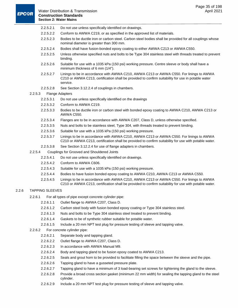
Page 35 of 198 Water Distribution & Transmission April 2021 Construction Standards Section 2: Water Mains
2.2.5.2.1 Do not use unless specifically identified on drawings.
2.2.5.2.2 Conform to AWWA C219, or as specified in the approved list of materials.
2.2.5.2.3 Bodies to be ductile iron or carbon steel. Carbon steel bodies shall be provided for all couplings whose
nominal diameter is greater than 300 mm.
2.2.5.2.4 Bodies shall have fusion-bonded epoxy coating to either AWWA C213 or AWWA C550.
2.2.5.2.5 Unless otherwise specified nuts and bolts to be Type 304 stainless steel with threads treated to prevent
binding.
2.2.5.2.6 Suitable for use with a 1035 kPa (150 psi) working pressure. Centre sleeve or body shall have a
minimum thickness of 6 mm (1/4").
2.2.5.2.7 Linings to be in accordance with AWWA C210, AWWA C213 or AWWA C550. For linings to AWWA
C210 or AWWA C213, certification shall be provided to confirm suitability for use in potable water
service.
2.2.5.2.8 See Section 3.12.2.4 of couplings in chambers.
2.2.5.3 Flange Adapters
2.2.5.3.1 Do not use unless specifically identified on the drawings
2.2.5.3.2 Conform to AWWA C219.
2.2.5.3.3 Bodies to be ductile iron or carbon steel with bonded epoxy coating to AWWA C210, AWWA C213 or
AWWA C550.
2.2.5.3.4 Flanges are to be in accordance with AWWA C207, Class D, unless otherwise specified.
2.2.5.3.5 Nuts and bolts to be stainless steel, Type 304, with threads treated to prevent binding.
2.2.5.3.6 Suitable for use with a 1035 kPa (150 psi) working pressure.
2.2.5.3.7 Linings to be in accordance with AWWA C210, AWWA C213 or AWWA C550. For linings to AWWA
C210 or AWWA C213, certification shall be provided to confirm suitability for use with potable water.
2.2.5.3.8 See Section 3.12.2.4 for use of flange adapters in chambers.
2.2.5.4 Couplings for Grooved and Shouldered Joints
2.2.5.4.1 Do not use unless specifically identified on drawings.
2.2.5.4.2 Conform to AWWA C606.
2.2.5.4.3 Suitable for use with a 1035 kPa (150 psi) working pressure.
2.2.5.4.4 Bodies to have fusion bonded epoxy coating to AWWA C210, AWWA C213 or AWWA C550.
2.2.5.4.5 Linings to be in accordance with AWWA C210, AWWA C213 or AWWA C550. For linings to AWWA
C210 or AWWA C213, certification shall be provided to confirm suitability for use with potable water.
2.2.6 TAPPING SLEEVES
2.2.6.1 For all types of pipe except concrete cylinder pipe:
2.2.6.1.1 Outlet flange to AWWA C207, Class D.
2.2.6.1.2 Carbon steel body with fusion bonded epoxy coating or Type 304 stainless steel.
2.2.6.1.3 Nuts and bolts to be Type 304 stainless steel treated to prevent binding.
2.2.6.1.4 Gaskets to be of synthetic rubber suitable for potable water.
2.2.6.1.5 Include a 20 mm NPT test plug for pressure testing of sleeve and tapping valve.
2.2.6.2 For concrete cylinder pipe:
2.2.6.2.1 Separate body and tapping gland.
2.2.6.2.2 Outlet flange to AWWA C207, Class D.
2.2.6.2.3 In accordance with AWWA Manual M9.
2.2.6.2.4 Body and tapping gland to be fusion epoxy coated to AWWA C213.
2.2.6.2.5 Seals and grout horn to be provided to facilitate filling the space between the sleeve and the pipe.
2.2.6.2.6 Tapping gland to have a gusseted pressure plate.
2.2.6.2.7 Tapping gland to have a minimum of 3 load-bearing set screws for tightening the gland to the sleeve.
2.2.6.2.8 Provide a broad cross section gasket (minimum 22 mm width) for sealing the tapping gland to the steel
cylinder.
2.2.6.2.9 Include a 20 mm NPT test plug for pressure testing of sleeve and tapping valve.

Page 36 of 198 Water Distribution & Transmission April 2021 Construction Standards Section 2: Water Mains
2.2.7 INSULATION AND WATER PROOFING
2.2.7.1 Any insulation/water proofing that is used must be manufactured using a process that does not utilize ozone-
depleting chemicals in any way.
2.2.7.2 For insulating pipes, use DOW HI-40 Styrofoam or similar approved board as shown on Drawing WA-002-001.
2.2.7.3 For insulating structures use DOW HI-40 Styrofoam, or similar approved board, or Urecon sprayed-in-place
Portafoam Polyurethane with Insul-Mastic I-M7505 heavy-duty roof coating.
2.2.7.4 For water proofing use Urecon sprayed-in-place Portafoam Polyurethane with Insul-Mastic I-M7505 heavy- duty
roof coating.
2.2.8 VALVE CHAMBERS AND BLOW-OFFS
2.2.8.1 Mainline Valve Chambers
2.2.8.1.1 Provide a pre-cast or cast-in-place reinforced concrete structure in accordance with Section 13 and
Water Drawings WA-003-003 and WA-003-010.
2.2.8.1.2 Provide a removable slab top roof.
2.2.8.1.3 Provide a 300 mm vertical separation between the chamber floor and all pipeline drain flanges.
2.2.8.1.4 Provide screw type valve casings for the mainline and pipeline drain valves.
2.2.8.2 Air Valve Chambers
2.2.8.2.1 Use 1800 mm diameter precast concrete manhole barrels to ASTM C478 for water mains up to 900 mm
diameter. Installation is to conform to Drawings WA-003-012 and WA-003-013.
2.2.8.2.2 For larger diameter water mains, use precast or cast-in-place concrete chambers.
2.2.8.3 Blow-Offs
2.2.8.3.1 Provide blow off hydrants or chambers as specified on the engineering drawings or in accordance with
detail drawings WA-002-005, or WA-002-006.
2.2.9 PIPE CASING
2.2.9.1 Steel pipe casing:
2.2.9.1.1 Conform to the requirements of AWWA C200, minimum tensile strength 207 MPa.
2.2.9.1.2 Wall thickness to be as specified on the engineering drawings.
2.2.9.2 PVC pipe casing:
2.2.9.2.1 To conform to the requirements of the City of Edmonton Design and Construction Standards Volume 3:
Drainage, Section 02535 – Sewers, Subsection 2.2 – Plastic Pipe.
2.2.9.2.2 Inside diameter of casing must be at least 50 mm greater than maximum outside diameter of carrier pipe
bell and insulator runners.
2.2.9.3 Use plastic/polyethylene carrier pipe insulators or approved equal.
2.2.9.4 See Drawing WA-002-011 for a typical pipe-in-casing configuration.
2.2.10 EXPANSION JOINTS
2.2.10.1 For use with steel pipe only.
2.2.10.2 Slip-type made of carbon steel.
2.2.10.3 Packing gland to consist of 5 rings of rubber and 4 rings of jute or an approved equal.
2.2.10.4 Stainless steel or chrome plated slip-pipe.
2.2.11 FLANGED PIPE GASKETS
2.2.11.1 Use for steel pipe flanges and steel, cast iron or ductile iron fitting flange
2.2.11.2 Use rubber sheet gaskets, 3.2 mm (1/8") thick, conforming to ASTM D1330, Grade I.
2.2.11.3 Gasket material to be natural or SBR type rubber.
2.2.12 CLAMPS, ANCHORS AND JOINT HARNESSES
2.2.12.1 Do not use unless specifically identified on drawings.
2.2.12.2 Joint Harness, for pipe fittings 150 mm to 600 mm, to consist of:
2.2.12.2.1 A socket clamp and washers;
2.2.12.2.2 A yoke; and
2.2.12.2.3 Straight stainless steel tie rods.

Page 37 of 198 Water Distribution & Transmission April 2021 Construction Standards Section 2: Water Mains
2.2.12.3 Joint Harness for 150 mm to 600 mm pipe only or for pipe and fittings without lugs, provide:
2.2.12.3.1 Two socket clamps and washers; and
2.2.12.3.2 Straight stainless steel tie rods.
2.2.12.4 For long sets provide approved tie rod couplers.
2.2.12.5 For concrete, steel cylinder type pipe, use bell bolt joints or welded joints on either side of fittings or at valve
chambers.
2.3 EXECUTION
2.3.1 MANUFACTURER’S RECOMMENDATIONS
2.3.1.1 The manufacturer’s recommended installation procedure is to be obtained and followed for all materials installed.
In the case of discrepancy between the manufacturer's requirements and these specifications, advise EPCOR
and request instruction before proceeding.
2.3.2 INSPECTION OF MATERIAL BEFORE INSTALLATION
2.3.2.1 Receiving material
2.3.2.1.1 Before unloading, inspect the general condition of load for adequacy of packing and bracing, any signs
of shifting and any signs of damage to materials.
2.3.2.1.2 Where the load has shifted badly and material appears significantly damaged, reject the entire load.
2.3.2.1.3 While unloading check each piece of pipe and/or each fitting for:
2.3.2.1.3.1 The required manufacturers markings;
2.3.2.1.3.2 The mark of the manufacturers testing agency;
2.3.2.1.3.3 Damage to joint ends or surfaces;
2.3.2.1.3.4 Damage to coating or lining; and
2.3.2.1.3.5 Other visually apparent damage.
2.3.2.1.4 For steel pipe and fittings, provide 100% coverage of coated surfaces with an approved Holiday detector
to detect damage and defects before stockpiling or stringing steel pipe.
2.3.2.1.5 If EPCOR is supplying the materials, note all damage and defects in writing and submit a copy of the
receiving inspection report to EPCOR. Rejected pipe will be replaced by EPCOR or EPCOR’s supplier.
However, unless the piece is rejected entirely, damage and defects discovered at the time of receiving
shall be repaired by the Contractor. All materials, once accepted by the Contractor, become the
responsibility of the Contractor until EPCOR accepts the installation.
2.3.2.1.6 If the Contractor is supplying the materials, submit a receiving inspection report as noted in Clause
2.3.2.1.5. Repair damages or defects and replace rejects.
2.3.2.1.7 Maintain a continuous file of all receiving inspection reports at the job site, to be accessible for review by
the EPCOR.
2.3.2.1.8 The Contractor is responsible for the safe storage of pipe after delivery and before installation and for
handling and transportation between the storage site and the final location.
2.3.2.2 Installing material
2.3.2.2.1 Visually inspect joint ends and surfaces for damage or defects immediately before installation. Reject
and remove from site any unacceptable pipe or fittings.
2.3.2.2.2 For steel materials, provide 100% coverage of coatings with an approved Holiday Detector immediately
before installation paying particular attention to repaired areas. Mark defective areas for further repair.
2.3.2.2.3 Re-check repairs to coatings with an approved Holiday Detector before laying. If necessary, reject the
piece and remove it from the job site.
2.3.3 HANDLING PIPE AND FITTINGS
2.3.3.1 String pipe and fittings along the trench in the order designated on the Construction Drawings.
2.3.3.2 Use proper belt slings and equipment for handling pipe and fittings at all times.
2.3.3.3 Support pipe and fittings in suitably shaped wooden blocks to prevent damage to the coating.
2.3.3.4 Keep joint ends and the inside of the pipe clean. Cover the joint ends with burlap or caps and plugs until required.
2.3.3.5 Inspect pipe and fittings for defects in the coating and lining before placing in the trench.
2.3.3.6 Repair defects in coating and lining as follows:
2.3.3.6.1 Polyethylene - by priming and cold taping;

Page 38 of 198 Water Distribution & Transmission April 2021 Construction Standards Section 2: Water Mains
2.3.3.6.2 Cement mortar - by patching with mortar to AWWA C104;
2.3.3.6.3 Epoxy - in accordance with AWWA C210, AWWA C213 or AWWA C216; and
2.3.3.6.4 Others – in accordance with suppliers’ instructions and applicable standards, with EPCOR approval.
2.3.4 OPERATION OF BOUNDARY VALVES
2.3.4.1 Refer to Section 9 for guidance on operating boundary valves.
2.3.4.2 Review operation procedures and requirements for boundary valves with EPCOR Water Inspector at the pre-
construction meeting.
2.3.5 LAYING PIPE
2.3.5.1 Lay and join PVC pipe in accordance with AWWA Manual M23 and AWWA Standard C605.
2.3.5.2 Lay and join PE/HDPE pipe in accordance with Plastics Pipe Institute Handbook of Polyethylene Pipe and AWWA
Manual M55. Install in accordance with the City of Edmonton Design and Construction Standards Volume 3:
Drainage, Section 02531 – Sewage Force Mains, Subsection 3.3.3. Polyethylene Pipe.
2.3.5.3 Lay and join concrete, steel cylinder pipe in accordance with AWWA Manual M9.
2.3.5.4 Lay concrete, steel cylinder pipe and PVC pipe with bell ends in the direction of laying.
2.3.5.5 Lay and join ductile iron pipe and cast iron fittings in accordance with AWWA C600.
2.3.5.6 Apply pipe joint lubricant approved for potable water systems in strictly accordance with the manufacturer's
recommended application procedure. Do not apply excessively.
2.3.5.7 Lay pipes on prepared bedding with excavated joint holes that allow the joint ends to be kept clean of soil and
bedding material, to facilitate making the joint and to avoid load concentration on the bells or couplings.
2.3.5.7.1 Pipe bedding shall be undertaken in accordance with Section 6.
2.3.5.8 Lay the pipes in lengths shorter than the standard where disturbed ground is encountered or where designated
on the drawings.
2.3.5.9 Test bolting for mechanical joints, bolted couplings and flanges on completion using a torque wrench. Torque
shall conform to recommendations of the pipe or fitting manufacturer. Bolt in sequence.
2.3.5.10 Cut pipes as required to install fittings, valves or hydrants. Make cuts using the recommended tools to ensure
square cut and correctly beveled ends.
2.3.5.11 Provide a concrete thrust block at each dead end, valve, tee, bend, hydrant, reducer, transition coupling, or fitting
and at any change in pipe diameter or direction. Construct concrete thrust blocks against undisturbed soil and in
conformance with Drawings WA-002-002, WA-002-007, WA-002-008a, WA-002-008b, WA-002-009 and WA-004-
001 or as shown on the construction drawings.
2.3.5.11.1 In areas where the geotechnical report has identified soil bearing capacities of less than 72 kPa, install
thrust blocks in accordance with the specific thrust block detail shown on the construction drawings.
2.3.5.11.2 Oversized thrust block calculations must be submitted under seal as part of the engineering drawing
submission process per Section 1.4.2.3.
2.3.5.12 Joint restraints may be required in conjunction with thrust blocks. Calculations must be submitted to EPCOR prior
to drawing approval per Section 1.4.2.4.
2.3.6 WELDING OF PIPE
2.3.6.1 Field welding of steel pipe and concrete cylinder pipe shall be in accordance with the following requirements:
2.3.6.1.1 Call a meeting 2 weeks in advance of any welding to clarify terms of reference, welding procedures and
inspection parameters.
2.3.6.1.2 Perform welding using weld procedures developed in accordance with CSA Z662. Submit a copy of
those welding procedures to EPCOR at least one week prior to commencing welding.
2.3.6.1.3 Welders shall hold a current "Grade B Pressure Welder Certificate of Competency" issued by the Alberta
Boilers Safety Association (ABSA).
2.3.6.1.4 Use radiography of a welder’s initial weld to confirm that the welder is capable of welding to the
appropriate welding procedure.
2.3.6.1.5 For cement mortar lined steel pipe, cut the lining back at the joint to the distance recommended by the
manufacturer and make good with an approved mortar after welding.
2.3.6.1.6 Repair welds, if allowed by the EPCOR Inspector, to CSA Z662.
2.3.6.1.7 Coat welded joints in steel pipe in accordance with AWWA C209.
2.3.6.1.8 Inspect and test the pipe coating with an approved high voltage Holiday Detector prior to backfill.

Page 39 of 198 Water Distribution & Transmission April 2021 Construction Standards Section 2: Water Mains
2.3.7 JOINTING PIPE
2.3.7.1 For Joints Other than Welded Joints in Steel Pipe:
2.3.7.2 Follow the manufacturer’s recommended procedure and use gauges and/or other approved devices to check the
joint during installation and after completion.
2.3.7.3 For Couplings:
2.3.7.3.1 Install couplings in accordance with applicable standards (e.g. AWWA C219 for Bolted Sleeve
Couplings) and manufacturer’s instructions or guidelines.
2.3.7.3.2 All reducer couplings and transition couplings require thrust blocks, pipe stops or restraint, as
designated on drawings or as instructed by the EPCOR inspector.
2.3.7.4 For Welded Joints on Steel Pipe:
2.3.7.4.1 Make mill certificate copies available to the EPCOR at least 2 weeks in advance of any field welding.
2.3.7.4.2 Radiographic inspection of the welded joints shall be conducted. The welded joints must meet the
standard of acceptability in accordance with CSA Z662. In the event that more than 10% of the joints
radiographically inspected required repairs or replacements, 100% inspection of welds will be performed
until a satisfactory weld production is established.
2.3.7.4.3 The radiographic interpretation of the welded joints shall be final.
2.3.7.4.4 All initial and subsequent inspection costs incurred for testing weld repairs or replacements are the
responsibility of the Contractor.
2.3.7.4.5 For welded joints on steel pipe do the following additional testing, if ordered at random or based upon
the X-ray or radiographic inspection data:
2.3.7.4.5.1 Select joints for coupon testing and cut eight coupons at 45º intervals from the welded joint;
2.3.7.4.5.2 Test four coupons for tensile strength, two for bending strength and one for nick-break strength. If a coupon fails any one of these tests, test the remaining coupon with that same test; and
2.3.7.4.5.3 Failure of any coupon test is cause for rejecting the weld.
2.3.7.4.6 If a weld is rejected for coupon test failure another joint made by the same welders shall be subjected to
the coupon test immediately; if the second joint fails to pass the coupon test, that welder will not be
allowed to continue welding on this Contract.
2.3.8 CONNECTING TO EXISTING MAINS
2.3.8.1 Notify the EPCOR Engineer at least 30 days before starting a connection to an existing water main.
2.3.8.1.1 Provide a written plan that:
2.3.8.1.1.1 Identifies necessary valve closures and any out of service hydrants;
2.3.8.1.1.2 Includes a contingency plan detailing steps to be taken in the event of problems occurring during the connection process;
2.3.8.1.1.3 Shows customers that will be affected by the work and how service will be maintained to those customers; and
2.3.8.1.1.4 Detail the precautions to be taken to ensure that there is no contamination of the water system.
2.3.8.1.2 Obtain approval from EPCOR to make the connection.
2.3.8.1.2.1 Note that connections to existing water mains 350 mm diameter or greater require a Shutdown Permit at least two weeks prior to the commencement of construction of the proposed connection. Coordinate with the EPCOR inspector to obtain a Shutdown Permit.
2.3.8.2 Temporary water supply (if required) must be provided by EPCOR Water Services. Temporary water (from hose
hookups) is only available during the summer months (May – October) due to the risk of freezing or at the
discretion of EPCOR Water Services. Temporary water is provided at the sole discretion of EPCOR Water
Services.
2.3.8.3 Notify the EPCOR Water Inspector 48 hours prior to commencing construction on the connection to the existing
system to confirm scheduling.
2.3.8.4 Ensure that all required equipment, tools, products, plans, procedures and manpower required to make the
connection expeditiously are on the site before starting.
2.3.8.5 Shut off boundary valves in the existing water main and make the necessary cut to connect. Refer to Section 9 for
guidance on operating boundary valves.
2.3.8.6 Use a tapping sleeve and valve where specifically designated to make a connection without taking the existing
water main out of service. Tapping of curved pipe is not permitted.
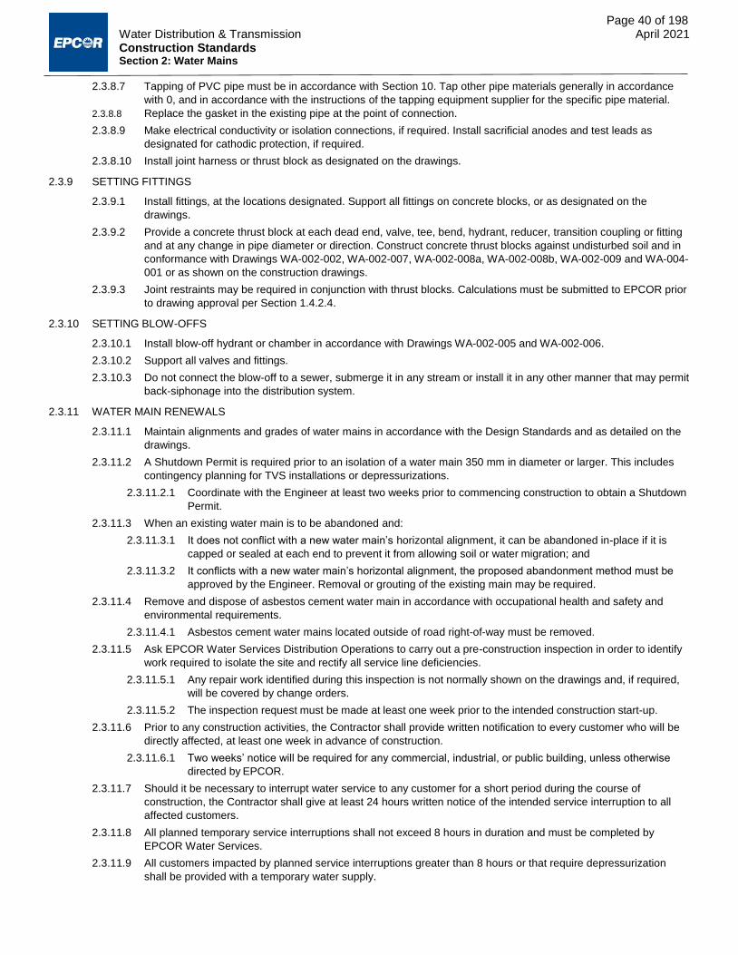
Page 40 of 198 Water Distribution & Transmission April 2021 Construction Standards Section 2: Water Mains
2.3.8.7 Tapping of PVC pipe must be in accordance with Section 10. Tap other pipe materials generally in accordance
with 0, and in accordance with the instructions of the tapping equipment supplier for the specific pipe material.
2.3.8.8 Replace the gasket in the existing pipe at the point of connection.
2.3.8.9 Make electrical conductivity or isolation connections, if required. Install sacrificial anodes and test leads as
designated for cathodic protection, if required.
2.3.8.10 Install joint harness or thrust block as designated on the drawings.
2.3.9 SETTING FITTINGS
2.3.9.1 Install fittings, at the locations designated. Support all fittings on concrete blocks, or as designated on the
drawings.
2.3.9.2 Provide a concrete thrust block at each dead end, valve, tee, bend, hydrant, reducer, transition coupling or fitting
and at any change in pipe diameter or direction. Construct concrete thrust blocks against undisturbed soil and in
conformance with Drawings WA-002-002, WA-002-007, WA-002-008a, WA-002-008b, WA-002-009 and WA-004-
001 or as shown on the construction drawings.
2.3.9.3 Joint restraints may be required in conjunction with thrust blocks. Calculations must be submitted to EPCOR prior
to drawing approval per Section 1.4.2.4.
2.3.10 SETTING BLOW-OFFS
2.3.10.1 Install blow-off hydrant or chamber in accordance with Drawings WA-002-005 and WA-002-006.
2.3.10.2 Support all valves and fittings.
2.3.10.3 Do not connect the blow-off to a sewer, submerge it in any stream or install it in any other manner that may permit
back-siphonage into the distribution system.
2.3.11 WATER MAIN RENEWALS
2.3.11.1 Maintain alignments and grades of water mains in accordance with the Design Standards and as detailed on the
drawings.
2.3.11.2 A Shutdown Permit is required prior to an isolation of a water main 350 mm in diameter or larger. This includes
contingency planning for TVS installations or depressurizations.
2.3.11.2.1 Coordinate with the Engineer at least two weeks prior to commencing construction to obtain a Shutdown
Permit.
2.3.11.3 When an existing water main is to be abandoned and:
2.3.11.3.1 It does not conflict with a new water main’s horizontal alignment, it can be abandoned in-place if it is
capped or sealed at each end to prevent it from allowing soil or water migration; and
2.3.11.3.2 It conflicts with a new water main’s horizontal alignment, the proposed abandonment method must be
approved by the Engineer. Removal or grouting of the existing main may be required.
2.3.11.4 Remove and dispose of asbestos cement water main in accordance with occupational health and safety and
environmental requirements.
2.3.11.4.1 Asbestos cement water mains located outside of road right-of-way must be removed.
2.3.11.5 Ask EPCOR Water Services Distribution Operations to carry out a pre-construction inspection in order to identify
work required to isolate the site and rectify all service line deficiencies.
2.3.11.5.1 Any repair work identified during this inspection is not normally shown on the drawings and, if required,
will be covered by change orders.
2.3.11.5.2 The inspection request must be made at least one week prior to the intended construction start-up.
2.3.11.6 Prior to any construction activities, the Contractor shall provide written notification to every customer who will be
directly affected, at least one week in advance of construction.
2.3.11.6.1 Two weeks’ notice will be required for any commercial, industrial, or public building, unless otherwise
directed by EPCOR.
2.3.11.7 Should it be necessary to interrupt water service to any customer for a short period during the course of
construction, the Contractor shall give at least 24 hours written notice of the intended service interruption to all
affected customers.
2.3.11.8 All planned temporary service interruptions shall not exceed 8 hours in duration and must be completed by
EPCOR Water Services.
2.3.11.9 All customers impacted by planned service interruptions greater than 8 hours or that require depressurization
shall be provided with a temporary water supply.

Page 41 of 198 Water Distribution & Transmission April 2021 Construction Standards Section 2: Water Mains
2.3.11.10 It is the Contractor’s responsibility to identify any obvious non-interruptible customers (hospitals, restaurants, day
care centres, schools, businesses that rely on process water, etc.) that may be impacted by a planned temporary
shut-down.
2.3.11.10.1 These customers shall be provided with temporary water supply at the beginning of the construction
project.
2.3.11.11 Piping for temporary services shall conform to NSF Standard 14 for potable water use and consist of a temporary
main (header) having a diameter not less than 40 mm and laterals not less than 13 mm in diameter.
2.3.11.11.1 Existing 40 mm to 50 mm services will require at least two laterals and 100 mm to 200 mm services will
require two 40 mm laterals.
2.3.11.12 Prior to setting up temporary service piping the contractor shall request (minimum of 1 week notice) to have the
hydrant checked by EPCOR to confirm it is in good operating condition.
2.3.11.12.1 The Contractor will be responsible for any subsequent damage resulting from improper operation of the
hydrant until temporary services are removed.
2.3.11.12.2 The contractor must notify EPCOR Water Distribution Operations after removing temporary piping for
inspection of the hydrant.
2.3.11.13 The contractor is responsible for metering all temporary water use on each project.
2.3.11.13.1 Approved meters are available from EPCOR Water Services.
2.3.11.13.2 Meters must not be installed directly on the hydrant nozzles and appropriate back flow preventers must
be used.
2.3.11.13.3 The Contractor must ensure their backflow preventers are tested and certified annually.
2.3.11.13.4 Copies of the annual certifications must be provided to EPCOR.
2.3.11.14 If a temporary shutdown is required, orange hydrant disks must be installed on all hydrants rendered out of
service by the shutdown.
2.3.11.14.1 Once the shutdown is completed, the disks must be removed.
2.3.11.14.2 Out of service hydrants must be reported to EPCOR’s construction inspector.
2.3.11.15 Isolate the site prior to construction.
2.3.11.15.1 Replace all boundary valves identified during the pre-construction inspection as faulty, i.e. not operable
or not providing a tight shut off.
2.3.11.15.2 If a valve cannot be repaired prior to construction, the planned temporary shut-down may need to be
extended to the next available boundary valves.
2.3.11.15.2.1 The Contractor is responsible for identifying any customers impacted by this extension and providing adequate notification or temporary water supplies if required.
2.3.11.16 Replace faulty service valves.
2.3.11.16.1 Replace all service valves, main stops and service piping for services where the distance from the water
main to the property line is less than 1.5 m.
2.3.11.16.2 Replace services with approved water service materials, from the main to the property line, including
service valves.
2.3.11.17 Refer to Section 8 for guidance on accepting testing for water mains.
2.3.11.18 A disturbed soil caveat must be registered on title for those lots where a water main is installed, abandoned in
place, or removed from within the lot or adjacent walkway, lane, or public utility lot.
2.3.11.19 Upon the completion and passing of the hydrostatic testing, new water mains are required to have bacteriological
sampling and taste and odour testing completed per Section 8.
2.3.11.19.1 These results of these tests indicating a pass must be completed prior to placing the new water main
into service.
2.3.12 PIPE CASINGS
2.3.12.1 Install casings by open trench, augering, or other trenchless installation method in conformance with the City of
Edmonton Design and Construction Standards Volume 2: Roadways, Section 3.1 – Trench and Backfill.
2.3.12.2 Alignment and grade tolerances shall conform to Section 2.3.15.
2.3.12.3 Install PVC casings to the bedding and backfill requirements for PVC sewers in accordance with the City of
Edmonton Design and Construction Standards Volume 2: Roadways, Section 3.1 – Trench and Backfill.
2.3.12.3.1 Install other casings to the same bedding and backfill specifications required for water mains of the
same material as the casing.

Page 42 of 198 Water Distribution & Transmission April 2021 Construction Standards Section 2: Water Mains
2.3.12.4 Securely strap 6 mil minimum polyethylene sheeting to carrier and casing pipe at both ends of casing, or install
approved purpose made casing boot.
2.3.12.5 Do not grout the annular space between the carrier pipe and casing.
2.3.13 INSULATION
2.3.13.1 Install insulation in accordance with manufacturer’s recommended installation procedures and as shown on the
drawings. Refer to Detail WA-002-001.
2.3.14 VALVE AND BLOW OFF CHAMBERS
2.3.14.1 Waterproof chamber using materials and methods approved by EPCOR.
2.3.14.2 Position the appurtenances on the pipe to provide sufficient room for removal of the coupling.
2.3.14.3 Provide ventilation piping for the automatic air valve at locations where the groundwater elevation is expected to
be above the elevation of the air valve.
2.3.14.4 Install manual air vents in accordance with Details WA-003-014 to WA-003-018.
2.3.15 ALIGNMENT AND GRADE
2.3.15.1 Install the pipe to the line and grade designated and check by means of a laser or off-set line and batter boards.
2.3.15.2 Use a procedure for checking the alignment and grade of the trench, installed pipe and fittings, so that specified
tolerances and joint deflections are not exceeded.
2.3.15.2.1 The Engineer will check alignment and grade at his or her discretion.
2.3.15.2.2 Supply grade sheets for the Engineer to check.
2.3.15.3 Upon inspection, EPCOR may order completed pipe, fittings, valves or hydrants to be removed and reinstalled
because of unacceptable deviations from specified line and grade.
2.3.15.3.1 The cost of repairs or consequent damage attributable to excessive deviations is the responsibility of the
Contractor.
2.3.15.4 Use a detailed layout as outlined in the City of Edmonton Design and Construction Standards Volume 1: General,
Chapter 11 – Construction Facilities, Section 8 – Survey.
2.3.15.5 For water main renewals, see Section 1.1.1.
2.3.15.6 Unless otherwise marked on the drawings, install the water main according to the depths specified in the Design
Standards.
2.3.15.7 Obtain prior written direction from EPCOR for insulation requirements for water mains and water services if the
water main cannot be installed at the specified depth.
2.3.15.8 Lay out the location of and install all fittings, valves, hydrants and other appurtenances as identified on the
drawings.
2.3.15.9 Deflection at any joint shall not exceed the manufacturer’s allowable deflection for that diameter, length of pipe
and type of joint.
2.3.15.10 Maximum allowable tolerances in alignment and grade are as follows:
2.3.15.10.1 Grade: +_ 40 mm
2.3.15.10.2 Alignment: +_ 100 mm
2.3.15.10.3 Any horizontal alignment variation in excess of +_ 600 mm will require reconstruction and the submission
of a detailed written incident report.
2.3.15.10.4 Alignment, grade and location of standard and non-standard fittings shall be in accordance with the
drawings.
2.3.16 CLEANING OF WATER MAINS
2.3.16.1 Securely cover exposed ends of pipe at the end of every workday.
2.3.16.2 Do not stow or store materials, tools or accessories inside pipe.
2.3.16.3 Sweep, swab or pig the water main to ensure dirt, debris, excess gasket lubricant and other deleterious materials
are removed prior to commissioning.
2.3.16.4 All construction must be carried out in clean and sanitary conditions.
2.3.17 INSPECTION AND TESTING
2.3.17.1 Before Backfill

Page 43 of 198 Water Distribution & Transmission April 2021 Construction Standards Section 2: Water Mains
2.3.17.1.1 Before coating and backfilling over the joints, the Contractor may, for the Contractor’s own assurance,
carry out a low pressure air test (welded steel pipe only), a water test or any other test deemed
necessary. Any such testing will be at the sole risk and cost of the Contractor.
2.3.17.1.2 Before backfilling over the joints do the following inspection and testing:
2.3.17.1.2.1 Visual inspection of mortared joints for structural integrity and absence of cracking or spalling; and
2.3.17.1.2.2 100% coverage of the joint coatings (other than mortar) with an approved Holiday Detector.
2.3.17.2 Hydrostatic Testing
2.3.17.2.1 Hydrostatic testing shall be performed in accordance with Section 8. All documentation referenced in
these guidelines is to be completed and submitted to the Engineer.
2.3.17.3 Deflection Testing of Flexible Water Transmission Mains
2.3.17.3.1 A mandrel, as defined below, shall be pulled through flexible pipe greater than or equal to 600 mm
diameter and less than 1200 mm diameter to demonstrate that the pipe deflection does not exceed the
maximum allowable in the applicable AWWA Standard or Manual.
2.3.17.3.1.1 If an alternative method of pipe deflection determination, such as an electronic gauging pig, is proposed by the Contractor, the inspection method must be approved by EPCOR prior to testing.
2.3.17.3.2 The device shall be pulled manually through the pipe 24 hours or more after the completion of backfilling
to surface for roadway subgrade, prior to the installation of main line valves and in conjunction with the
closed circuit television inspection.
2.3.17.3.3 The mandrel shall be cylindrical in shape and constructed with an odd number of evenly spaced arms or
prongs (a minimum of 9).
2.3.17.3.3.1 The minimum diameter of the circle scribed around the outside of the mandrel arms shall be equal to the allowable computed deflected internal diameter minus 1.0 mm.
2.3.17.3.3.2 The contact length of the mandrel shall be measured between the points of contact on the mandrel arm or between sets of prongs. This length shall not be less than that shown in Table 2.1.
Table 2.1: Minimum contact length for mandrel testing
Nominal Pipe Diameter (mm) Minimum Contact Length (mm)
600 500
750 600
900 750
1050 850
2.3.17.3.4 The mandrel shall be checked with a Go/No-Go proving ring.
2.3.17.3.4.1 The proving ring shall have a diameter equal to the computed deflected diameter +_ 2 mm.
2.3.17.3.4.2 An acceptable mandrel shall not pass through the proving ring.
2.3.17.3.4.3 The proving ring shall be fabricated from 6 mm minimum thick steel.
2.3.17.3.5 Any section of pipe that does not allow the mandrel to pass shall be considered to have failed the
deflection test.
2.3.17.4 Inspection of Larger Diameter Pipes
2.3.17.4.1 For pipes 1200 mm diameter or larger, assist the Engineer in performing a physical walk-through
inspection to ensure all interior joints are satisfactorily completed and no visible damage to the pipe is
evident.
2.3.17.4.2 Vertical and horizontal measurements will be taken at mid-length of each pipe length to confirm that any
pipe deflections are less than the maximum allowed by the applicable AWWA Standard.
2.3.17.4.3 A report will be prepared by the Engineer describing the observed pipe condition and discussing the
implications of the pipe measurements taken.
2.3.17.4.4 Colour photographs will be taken by the Engineer to show general pipe condition and any abnormalities
encountered.
2.3.17.4.5 All confined space entry safety procedures shall be observed.
2.3.17.4.6 Inspection must be carried out in clean and sanitary conditions.

Page 44 of 198 Water Distribution & Transmission April 2021 Construction Standards Section 2: Water Mains
2.3.17.5 Televised Inspection
2.3.17.5.1 Inspections must be carried out in clean and sanitary conditions.
2.3.17.5.2 For television inspections of pipes 600 mm to 1050 mm diameter, the television camera used shall be
specifically designed and constructed for the purpose.
2.3.17.5.3 Lighting for the camera shall provide a clear picture of the entire periphery of the pipe.
2.3.17.5.4 The camera shall be operative in 100% humidity conditions.
2.3.17.5.5 The camera, television monitor and other components of the video system shall be capable of producing
picture quality to the satisfaction of EPCOR.
2.3.17.5.5.1 If unsatisfactory, equipment shall be removed and no payment will be made for that inspection.
2.3.17.5.6 The camera shall be moved through the main at the main's spring line in either direction at a moderate
rate, stopping when necessary to permit proper documentation of the pipeline condition.
2.3.17.5.7 In no case will the television camera be pulled at a speed greater than 9 metres per minute.
2.3.17.5.8 Manual winches, power winches, television cable and powered rewinds or other devices that do not
obstruct the camera view or interfere with proper documentation of the pipe conditions shall be used to
move the camera through the water main.
2.3.17.5.9 If, during the inspection operation, the television camera will not pass through the entire section between
valves, the Contractor shall set up the equipment so that the inspection can be performed from the
opposite valve location.
2.3.17.5.9.1 If, again, the camera fails to pass through the entire section, the inspection shall be considered complete and no additional inspection work will be required until the Contractor corrects the problem.
2.3.17.5.10 Suitable means of communication shall be set up between the two ends of the section being inspected
to ensure good communications between members of the crew.
2.3.17.5.11 Measurement for location of defects shall be above ground by means of a meter device.
2.3.17.5.11.1 Marking on the cable or the like, which would require interpolation will not be allowed.
2.3.17.5.11.2 Accuracy of the distance meter shall be checked by use of a walking meter, roll-a-tape or other suitable device to the satisfaction of EPCOR.
2.3.17.5.12 Disinfect equipment shall conform to AWWA Standards and to the satisfaction of the Engineer prior to
using it to inspect the water main.
2.3.17.5.13 Documentation of the televised inspection shall be as follows:
2.3.17.5.13.1 Television Inspection Logs: 2.3.17.5.13.1.1 Keep printed location records that clearly show the location of all pipe defects observed
during inspection;
2.3.17.5.13.1.2 Record other points of significance such as unusual conditions, broken pipe, presence of
scale and corrosion and other discernible features; and
2.3.17.5.13.1.3 Provide one copy of all records to EPCOR.
2.3.17.5.13.2 Photographs: 2.3.17.5.13.2.1 Take instant developing, standard-size or digital photographs of the television picture of
problems if so requested by EPCOR.
2.3.17.5.13.3 Video Recordings: 2.3.17.5.13.3.1 The purpose of video recording shall be to supply a visual and audio record of problem
areas of the mains that may be replayed.
2.3.17.5.13.3.2 The video recording shall be of an appropriate media format.
2.3.17.5.13.3.3 The practice of dubbing and mixing of video shall not be permitted.
2.3.17.5.13.3.4 The Engineer will only view the original unedited tapes.
2.3.17.5.13.3.5 Title to the video shall be with EPCOR and only the original (first generation) unedited
video shall be forwarded to EPCOR.
2.3.17.5.13.3.6 Video recording playback shall be at the same speed that it was recorded.
2.3.17.5.13.3.7 Colour, slow motion or stop-motion playback features may be supplied at the option of
the Contractor.
2.3.17.5.13.3.8 The Contractor shall have all video and necessary playback equipment readily
accessible for review by the Engineer during the project.

Page 45 of 198 Water Distribution & Transmission April 2021 Construction Standards Section 2: Water Mains
2.3.18 CLEAN-UP
2.3.18.1 Remove all surplus materials and products when the work has been installed and finished.
2.3.18.2 Remove all Contractor's plant, equipment and temporary facilities.
2.3.18.3 Provide a final grading of all bare soil and gravel surfaces.
2.3.18.4 Flush and sweep all pavements, sidewalks, curbs and gutters clean of dirt and debris due to construction.
2.3.19 FLUSHING AND DISINFECTING
2.3.19.1 Perform flushing and disinfection in accordance with Section 8.
2.3.19.2 Submit completed copies of documentation referenced in the guidelines.
2.3.19.3 Flushing and disinfection procedures are to be reviewed with the EPCOR Water Inspector at the pre-construction
meeting.
2.3.19.4 Prior to flushing and disinfection of water mains, prepare a plan per Section 8.2.
2.3.19.5 Submit the plan to EPCOR with construction drawings and obtain approval prior to commencing flushing and
disinfection operations.
2.3.19.5.1 Obtain applicable permits.
2.3.19.6 At no time during flushing and disinfection operations should more than one boundary valve between the water
system under construction and adjacent water systems be open.
2.3.19.7 Do not dispose of water containing chlorine or volatile or waste materials, such as mineral spirits and paint
thinner, into any surface waterway or storm or sanitary sewer. All discharges must comply with all applicable Acts,
Regulations, Bylaws and Standards.
2.3.19.7.1 This requirement may be relaxed only if written approval to exceed the limit concerned, from the
authority having jurisdiction over the waterway or sewer, is provided to the Engineer.
2.3.20 SAMPLING
2.3.20.1 Perform sampling in accordance with Section 8.
2.3.20.2 Assist the Inspector in taking water samples for quality control testing purposes.
2.3.20.3 No more than 72 hours prior to putting a newly constructed water main into service, the following water quality
parameters must be measured and found to be within the limits specified in Table 2.2.
Table 2.2: Required water quality parameters for new water mains
PARAMETER VALUE UNIT
E.Coli (EC) Absence -
Total Coliform (TC) Absence -
Residual Chlorine 1.0 to 2.4 mg/L
Free Chlorine < 0.1 mg/L
pH 7.3 to 8.3 -
Turbidity 0 to 3.0 NTU
Colour 0 to 2.0 TCU
V.O.C.'s
< 0.010 (GCDWQ MACs
for components)
mg/L
Pipe Lubricant Negative -
Taste and Odour Inoffensive -
UV Scan Negative Vs. Plant
Water -
2.3.20.4 Should any of the above parameters be outside the limits shown in Table 2.2, notify EPCOR and obtain directions
for remedial action.
2.3.20.5 If the first taste and odour sample fails, all subsequent flushing will be at the cost of the project proponent.
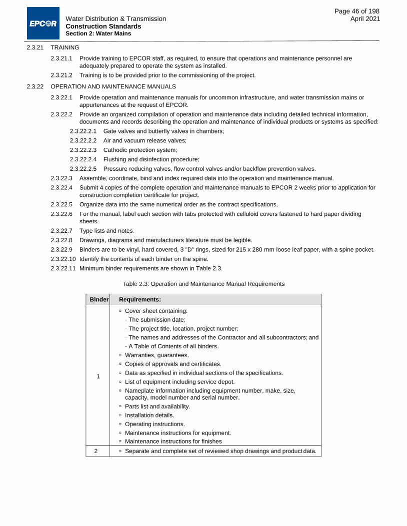
Page 46 of 198 Water Distribution & Transmission April 2021 Construction Standards Section 2: Water Mains
2.3.21 TRAINING
2.3.21.1 Provide training to EPCOR staff, as required, to ensure that operations and maintenance personnel are
adequately prepared to operate the system as installed.
2.3.21.2 Training is to be provided prior to the commissioning of the project.
2.3.22 OPERATION AND MAINTENANCE MANUALS
2.3.22.1 Provide operation and maintenance manuals for uncommon infrastructure, and water transmission mains or
appurtenances at the request of EPCOR.
2.3.22.2 Provide an organized compilation of operation and maintenance data including detailed technical information,
documents and records describing the operation and maintenance of individual products or systems as specified:
2.3.22.2.1 Gate valves and butterfly valves in chambers;
2.3.22.2.2 Air and vacuum release valves;
2.3.22.2.3 Cathodic protection system;
2.3.22.2.4 Flushing and disinfection procedure;
2.3.22.2.5 Pressure reducing valves, flow control valves and/or backflow prevention valves.
2.3.22.3 Assemble, coordinate, bind and index required data into the operation and maintenance manual.
2.3.22.4 Submit 4 copies of the complete operation and maintenance manuals to EPCOR 2 weeks prior to application for
construction completion certificate for project.
2.3.22.5 Organize data into the same numerical order as the contract specifications.
2.3.22.6 For the manual, label each section with tabs protected with celluloid covers fastened to hard paper dividing
sheets.
2.3.22.7 Type lists and notes.
2.3.22.8 Drawings, diagrams and manufacturers literature must be legible.
2.3.22.9 Binders are to be vinyl, hard covered, 3 "D" rings, sized for 215 x 280 mm loose leaf paper, with a spine pocket.
2.3.22.10 Identify the contents of each binder on the spine.
2.3.22.11 Minimum binder requirements are shown in Table 2.3.
Table 2.3: Operation and Maintenance Manual Requirements
Binder Requirements:
1
Cover sheet containing:
- The submission date;
- The project title, location, project number;
- The names and addresses of the Contractor and all subcontractors; and
- A Table of Contents of all binders.
Warranties, guarantees.
Copies of approvals and certificates.
Data as specified in individual sections of the specifications.
List of equipment including service depot.
Nameplate information including equipment number, make, size, capacity, model number and serial number.
Parts list and availability.
Installation details.
Operating instructions.
Maintenance instructions for equipment.
Maintenance instructions for finishes
2 Separate and complete set of reviewed shop drawings and product data.

Page 47 of 198 Water Distribution & Transmission April 2021 Construction Standards Section 2: Water Mains
2.3.23 CONSTRUCTION COMPLETION INSPECTION
2.3.23.1 Boundary valves must be closed and secured until new water mains are accepted. Boundary valves may be
opened in accordance with Section 9 for the following construction activities:
2.3.23.1.1 Filling water-mains for wet-tapping of services;
2.3.23.1.2 Hydrostatic testing; and
2.3.23.1.3 Disinfection and subsequent flushing.
2.3.23.2 Request EPCOR to make an inspection when all installations have been completed and tested satisfactorily and
all cleanup has been completed. Set a time and date for the inspection.
2.3.23.3 Carry out the inspection. The Inspector shall make an agreed list of deficiencies and submit it to the Contractor.
EPCOR shall issue a construction completion certificate if there are no deficiencies.
2.3.23.4 Rectify the deficiencies listed on the agreed deficiency list resulting from the inspection. Request the Inspector to
make another inspection.
2.3.23.5 EPCOR shall issue a construction completion certificate when all deficiencies have been rectified.
2.3.24 PLACING WATER MAINS INTO SERVICE
2.3.24.1 Water mains must be commissioned as soon as reasonably possible after completion of construction. Comply
with all applicable requirements of Section 8 prior to placing a water main into service.
2.3.24.2 Coordinate with the EPCOR inspector to obtain approval from Transmission Operations prior to the
commissioning of water mains greater than 450 mm diameter.
2.3.24.3 Submit for approval a detailed written commissioning procedure outlining the following:
2.3.24.3.1 Sequence of boundary valve operation;
2.3.24.3.2 Water quality monitoring to be performed to ensure water quality in the existing water system is not
adversely affected by the commissioning;
2.3.24.3.3 Dechlorination of water discharges; and
2.3.24.3.4 Any other activities necessary to ensure satisfactory commissioning of the water main.
2.3.24.4 Notify the EPCOR Inspector 24 hours in advance of putting a newly constructed water main into service.
2.3.24.5 Refer Section 9 for guidance on operating boundary valves.
2.3.24.6 Maintain a watch for the event of a break in the new main to ensure that service in the surrounding areas will not
be unduly interrupted.
2.3.24.7 Standby and be prepared to perform any necessary sampling in the event that water quality concerns arise.
END OF SECTION

Construction Standards
Section 3 Water Valves
April 2021

Page 49 of 198 Water Distribution & Transmission April 2021 Construction Standards Section 3: Water Valves
3.1 GENERAL
3.1.1 SCOPE
3.1.1.1 This section refers to:
3.1.1.1.1 Buried Gate valves 100 mm to 1200 mm in diameter;
3.1.1.1.2 Gate valves in valve chambers;
3.1.1.1.3 Buried Tapping valves;
3.1.1.1.4 Buried Butterfly valves;
3.1.1.1.5 Butterfly valves in chambers; and
3.1.1.1.6 Check valves, air relief valves, flow control valves, pressure reducing valves and backflow preventers.
3.1.2 PRODUCT ACCEPTANCE
3.1.2.1 All water main valves shall be certified to NSF Standards 14 and 61 as acceptable for drinking water system
components.
3.1.2.2 Products are specified to be in accordance with a recognized standard such as AWWA, CSA, ASTM or ANSI.
3.1.2.3 Determining that a product complies with a standard requires:
3.1.2.3.1 Certification from the supplier or manufacturer to the effect that the product does meet the standard;
and/or
3.1.2.3.2 Testing in accordance with a recognized procedure such as the appropriate ASTM Standard.
3.1.2.4 In general, EPCOR will accept certification, if available, while reserving the right to call for additional testing as
necessary without incurring extra costs to EPCOR or the City.
3.1.2.5 A list of materials approved for use in the water distribution system is included as Section 11. In making this
determination, EPCOR is not strictly bound by the specified standards, but instead exercises judgement in the
best interests of the City of Edmonton in conjunction with EPCOR’s specific requirements. Unless prior written
approval is obtained, only materials that appear on this list shall be supplied.
3.1.2.6 Unless otherwise designated, all specification and standard references shall refer to the latest edition.
3.1.3 STANDARDS
3.1.3.1 Valves and appurtenances shall conform to the following standards:
3.1.3.1.1 ANSI B16.1 – Gray Iron Pipe Flanges and Flanged Fittings
3.1.3.1.2 ASSE 1013 – Reduced Pressure Principle Backflow Preventers and Reduced Pressure Principle Fire
Protection Backflow Preventers
3.1.3.1.3 ASTM A48 – Standard Specification for Gray Iron Castings
3.1.3.1.4 ASTM A126 – Standard Specification for Gray Iron Castings for Valves, Flanges, and Pipe Fittings
3.1.3.1.5 ASTM A240 – Standard Specification for Chromium and Chromium-Nickel Stainless Steel Plate, Sheet,
and Strip for Pressure Vessels for General Applications
3.1.3.1.6 ASTM A536 – Standard Specification for Ductile Iron Castings
3.1.3.1.7 ASTM B148 – Standard Specification for Aluminum-Bronze Sand Castings
3.1.3.1.8 AWWA C207 – Steel Pipe Flanges for Waterworks Service – Sizes 4 In. Through 144 In. (100 mm
Through 3600 mm)
3.1.3.1.9 AWWA C500 – Metal Seated Gate Valves for Water Supply Service
3.1.3.1.10 AWWA C504 – Rubber-Seated Butterfly Valves, 3 In. (75 mm) Through 72 In. (1,800 mm)
3.1.3.1.11 AWWA C508 – Swing Check Valves for Waterworks Service, 2-In. Through 24-In. (50-mm through 600-
mm) NPS
3.1.3.1.12 AWWA C509 – Resilient Seated Gate Valves for Water Supply Service
3.1.3.1.13 AWWA C510 – Double Check Valve Backflow Prevention Assembly
3.1.3.1.14 AWWA C511 – Reduced-Pressure Principle Backflow Prevention Assembly
3.1.3.1.15 AWWA C512 – Air Release, Air/Vacuum, and Combination Air Valves for Waterworks Service
3.1.3.1.16 AWWA C515 – Reduced-Wall, Resilient-Seated Gate Valves for Water Supply Service
3.1.3.1.17 AWWA C550 – Protective Epoxy Interior Coatings for Valves and Hydrants
3.1.3.1.18 CSA A23.2 – Test Methods and Standard Practices for Concrete

Page 50 of 198 Water Distribution & Transmission April 2021 Construction Standards Section 3: Water Valves
3.1.3.1.19 CSA B64 – Selection and Installation of Backflow Preventers / Maintenance and Field Testing of
Backflow Preventers
3.1.3.1.20 AWWA Canadian Cross Connection Control Manual
3.1.3.1.21 National Sanitation Foundation (NSF) Standard 14 – Plastics Piping System Components and Related
Materials
3.1.3.1.22 National Sanitation Foundation (NSF) Standard 61 – Drinking Water System Components - Health
Effects
3.1.3.1.23 Volume 3: Drainage, Section 03310 - Concrete for Water and Drainage Structures
3.1.3.2 All products shall be installed in accordance with the recommended installation procedures provided by the
manufacturer.
3.2 PRODUCTS
3.2.1 GATE VALVES
3.2.1.1 Direct-Bury Gate Valves
3.2.1.1.1 Use only for pipes 100 mm to 1200 mm in diameter.
3.2.1.1.2 Use a valve size equal to the pipe size, or as directed on the approved construction drawings.
3.2.1.1.3 Sizes 100 mm to 400 mm: bell ends, single ring gasket, and push-on joints for connecting to ductile iron
or PVC pipe (C.I.O.D.).
3.2.1.1.4 Sizes 450 mm to 1200 mm: mechanical joints (MJ), single ring gasket, for connecting to ductile iron or
PVC pipe (C.I.O.D.).
3.2.1.1.5 Conform to AWWA C500, C509 or C515; non-rising stem.
3.2.1.1.6 For blow-offs, valves to be flanged to AWWA C207, Class D.
3.2.1.1.7 All external nuts and bolts to be Type 304 stainless steel or better.
3.2.1.1.8 Provide a 50 mm square operating nut; that turns clockwise to close.
3.2.1.1.9 Provide "O" Ring seals for the valve stem.
3.2.1.1.10 Valve stem is to be Type 304 stainless steel or grade B, C, D, or E bronze as per AWWA C509.
3.2.1.1.11 Provide Type B (Screw Type) valve casing set with plug in accordance with Drawings WA-003-001 to
WA-003-005.
3.2.1.1.12 Provide Type B (Screw Type) middle extension for valves with depths in excess of 3.0 meters from top
of operating nut to surface grade of valve box.
3.2.1.1.13 Castings are to have no cracks, gas holes or flaws. Surfaces shall be reasonably smooth with no burnt
on sand. Casting runners, risers and fins shall be removed.
3.2.1.1.14 Castings shall be true to pattern, and within industry standard dimensional tolerances with no excessive
shrinkage or deformity.
3.2.1.1.15 Gray iron castings shall conform to ASTM A48, Class 30B.
3.2.1.1.16 Ductile iron castings (plugs and bonnets) shall conform to ASTM A536, grade 60-40-18.
3.2.1.2 Gate Valves in Chambers
3.2.1.2.1 Use only for valves 450 mm to 1500 mm diameter.
3.2.1.2.2 Match valve size to main pipe size.
3.2.1.2.3 Conform to AWWA C500, C509 or C515; non-rising stem, 50 mm square operating nut with hand wheel,
turning clock-wise to close, horizontal setting, bevel gears and position indicator.
3.2.1.2.4 Flanged ends to be in accordance with AWWA C207, Class D.
3.2.1.2.5 Valve stem is to be Type 304 stainless steel or grade B, C, D, or E bronze as per AWWA C509.
3.2.1.2.6 Provide "O" Ring seals for the valve stem.
3.2.1.2.7 Provide a by-pass and a gate valve to equalize pressure upon opening and closing the main valve. By-
pass valves shall conform to AWWA C500.
3.2.1.2.8 Where required, provide Type B screw type valve casing in accordance with Drawings WA-003-001 to
WA-003-005.
3.2.1.2.9 Provide shop drawings and test data sheets.
3.2.1.3 Tapping Valves
3.2.1.3.1 Conform to Section 3.2.1.1 or Section 3.4.1.2 depending on the application.

Page 51 of 198 Water Distribution & Transmission April 2021 Construction Standards Section 3: Water Valves
3.2.1.3.2 Inlet ends are to be in accordance with AWWA C207, Class D.
3.2.1.3.3 Outlet joints are to be as specified on the drawings.
3.2.2 BUTTERFLY VALVES
3.2.2.1 Direct-Bury Butterfly Valves
3.2.2.1.1 Use only for valve sizes 450 mm diameter and larger.
3.2.2.1.2 Match valve size to main pipe size.
3.2.2.1.3 Short body flanged, wafer, or fully lugged conforming to AWWA C504, class 150B.
3.2.2.1.4 Body and disc shall be cast iron, with rubber seat or an approved equal.
3.2.2.1.5 Provide "O" ring shaft seals in a removable corrosion resistant recess to allow seals to be replaced
without removing the valve shaft.
3.2.2.1.6 Provide a manual geared or travelling nut buried service actuator conforming to AWWA C504, turning
clock-wise to close with the following:
3.2.2.1.6.1 An actuator name plate mounted directly on the actuator indicating the actuator manufacturer, year of manufacture and model number;
3.2.2.1.6.2 A 50 mm square operating nut on top of the actuator;
3.2.2.1.6.3 A Type 304 stainless steel actuator input shaft; and
3.2.2.1.6.4 Actuator to transmit required valve opening and closing torque at an input torque of 100 lb-ft.
3.2.2.1.6.5 Actuator to be third party certified for conformance to AWWA C504.
3.2.2.1.7 Provide a Type B Screw Type valve casing set with a plug in accordance with Drawings WA-003-001 to
WA-003-005.
3.2.2.1.8 Provide Type B (Screw Type) middle extension for valves with depths in excess of 3.0 meters from top
of operating nut to surface grade of valve box.
3.2.2.1.9 Provide shop drawings of the valve and installation.
3.2.2.2 Butterfly Valves in Chambers
3.2.2.2.1 Use only for valve sizes 450 mm diameter and larger.
3.2.2.2.2 Match valve size to main pipe size.
3.2.2.2.3 Short-body flanged or wafer type conforming to AWWA C504, class 150B.
3.2.2.2.4 Body and disc of cast iron, with rubber seat or an approved equivalent.
3.2.2.2.5 Provide "O" ring shaft seals in a removable corrosion resistant recess to allow seals to be replaced
without removing the valve shaft.
3.2.2.2.6 Provide a manual geared or travelling nut actuator conforming to AWWA C504, 90% grease packed
turning clock-wise to close, with the following:
3.2.2.2.6.1 An actuator name plate mounted directly on the actuator indicating actuator manufacturer, year of manufacture and model number;
3.2.2.2.6.2 A horizontal hand wheel on a 50 mm square operating nut, on the top of the actuator;
3.2.2.2.6.3 A valve position indicator facing upward;
3.2.2.2.6.4 A Type 304 stainless steel actuator input shaft;
3.2.2.2.6.5 Actuator to transmit required valve opening and closing torque at an input torque of 100 ft-lb; and
3.2.2.2.6.6 Actuator to be third party certified for conformance to AWWA C504.
3.2.2.2.6.7 Provide a Type B Screw Type valve casing set with a plug in accordance with Drawings WA-003-001 to WA-003-005.
3.2.2.2.7 Provide shop drawings and test sheets of the valve and installation.
3.2.3 CHECK VALVES
3.2.3.1 Swing Check Valves
3.2.3.1.1 Do not use for pipes larger than 300 mm.
3.2.3.1.2 Conform to AWWA C508.
3.2.3.1.3 Cast iron body with bronze trimmed cast iron disc.
3.2.3.1.4 Flanged end to ANSI B16.1 (flat faced).
3.2.3.1.5 Bronze seat rings.

Page 52 of 198 Water Distribution & Transmission April 2021 Construction Standards Section 3: Water Valves
3.2.3.1.6 Valve shall have bolted cover, with an outside lever and adjustable spring assembly if designated on the
drawings.
3.2.3.1.7 Stainless steel shaft with double "O" rings and grease fittings at each end of shaft.
3.2.3.1.8 Minimum 1035 kPa working pressure.
3.2.3.2 Slanting disc check valves
3.2.3.2.1 Do not use for pipes 300 mm and under.
3.2.3.2.2 Cast iron body ASTM A126 Grade B.
3.2.3.2.3 Flanged ends (flat faced) to ANSI B16.1.
3.2.3.2.4 Ductile iron disc to ASTM A536.
3.2.3.2.5 Bronze seat ring and disc ring.
3.2.3.2.6 Stainless steel pivot pins to ASTM T303.
3.2.3.2.7 Stainless steel pivot pin bushing.
3.2.3.2.8 Valve position indicator with micro switch and mounting bracket.
3.2.3.2.9 Bottom mounted buffer for controlled closing.
3.2.3.2.10 Minimum 1035 kPa working pressure.
3.2.3.3 Double Door Check Valves
3.2.3.3.1 Cast iron body to ASTM A126.
3.2.3.3.2 Gates aluminum bronze to ASTM B148 Grade B.
3.2.3.3.3 Stainless steel spring – type 316.
3.2.3.3.4 Stainless steel stop pin.
3.2.3.3.5 Mount between ANSI 125# flanges.
3.2.3.3.6 Wafer or threaded lug type.
3.2.3.3.7 Valve seat Buna N.
3.2.3.3.8 Minimum 1035 kPa working pressure.
3.2.3.4 Silent Check Valves
3.2.3.4.1 Wafer style or globe type.
3.2.3.4.2 Cast iron ASTM A126 Grade B body.
3.2.3.4.3 Bronze trim.
3.2.3.4.4 Stainless steel spring – type 316.
3.2.3.4.5 Valve seat Buna N.
3.2.3.4.6 Replaceable seat and plug.
3.2.3.4.7 Suitable for horizontal or vertical flow.
3.2.3.4.8 Mount between ANSI 125 # flanges.
3.2.3.4.9 Minimum 1035 kPa working pressure.
3.2.3.5 Rubber Flapper Check Valves
3.2.3.5.1 Cast iron body.
3.2.3.5.2 Rubber lined, Buna N flapper.
3.2.3.5.3 Replaceable flapper with top cover plate.
3.2.3.5.4 O-ring seating.
3.2.3.5.5 Minimum 1035 kPa working pressure.
3.2.4 AIR VALVES
3.2.4.1 Automatic Air Release Valves
3.2.4.1.1 Conform to AWWA C512.
3.2.4.1.2 Single lever type.
3.2.4.1.3 Cast iron body.
3.2.4.1.4 Stainless steel float and other internal parts.
3.2.4.1.5 Threaded inlet.
3.2.4.1.6 Minimum 1035 kPa working pressure.

Page 53 of 198 Water Distribution & Transmission April 2021 Construction Standards Section 3: Water Valves
3.2.4.1.7 Except where specified otherwise.
3.2.4.2 Automatic Air and Vacuum Valves
3.2.4.2.1 Conform to AWWA C512.
3.2.4.2.2 Cast iron body.
3.2.4.2.3 Stainless steel float, ASTM A240.
3.2.4.2.4 Stainless steel guide shaft and bushing.
3.2.4.2.5 Flanged inlet and outlet to ANSI B16.1 Class 125 for valves 100 mm and larger.
3.2.4.2.6 Screwed inlet and outlet for valves 80 mm and smaller.
3.2.4.2.7 Sizes 80 mm and smaller to be equipped with a stainless steel diffuser screen.
3.2.4.2.8 Minimum 1035 kPa working pressure.
3.2.4.2.9 Except where specified otherwise.
3.2.4.3 Automatic Combination Air Valves
3.2.4.3.1 Conform to AWWA C512.
3.2.4.3.2 Cast iron body, cover and lever frame.
3.2.4.3.3 Stainless steel float.
3.2.4.3.4 Buna N seat.
3.2.4.3.5 Inlets up to 100 mm in diameter are to be threaded.
3.2.4.3.6 Inlets 100 to 200 mm in diameter are to be flanged to ANSI B16.1 Class 125.
3.2.4.3.7 Outlet to be plain with hood, threaded or flanged as shown.
3.2.4.3.8 Single or duplex body design, as indicated on the drawings.
3.2.4.3.9 Sizes 100 mm and larger to be equipped with an anti-slam device (surge check) mounted under
combination air valve.
3.2.4.3.10 Minimum 1035 kPa working pressure.
3.2.4.4 Manual Air Valves
3.2.4.4.1 Use full port gate valves with non-rising stem. Use 50 mm valves unless specified otherwise.
3.2.4.4.2 All stainless steel and/or bronze construction suitable for 1035 kPa operating pressure.
3.2.4.4.3 Provide threaded cap or plug or blank flange on each valve.
3.2.4.4.4 Refer to Drawings WA-003-014 to WA-003-018.
3.2.5 FLOW CONTROL VALVES
3.2.5.1 Provide a diaphragm type, in globe or angle pattern.
3.2.5.2 Valve body shall be cast iron, with bronze trim.
3.2.5.3 The diaphragm shall be fully supported.
3.2.5.4 Provide an "O" ring seat seal on main valve.
3.2.5.5 Flow shall be measured by an orifice in the inlet flange, and modulation shall be achieved by a single adjustment
pilot valve.
3.2.5.6 Provide a strainer and needle valve on pilot inlet lines.
3.2.6 PRESSURE REDUCING VALVES
3.2.6.1 Diaphragm type: single diaphragm for up to 200 mm valves and double diaphragm for 250 mm valves and larger.
3.2.6.2 Hydraulically operated.
3.2.6.3 Pilot controlled.
3.2.6.4 Globe style.
3.2.6.5 Flanged cast iron body to ANSI B16.1, Class 125.
3.2.6.6 Type 304 stainless steel seat and stem.
3.2.7 BACKFLOW PREVENTERS
3.2.7.1 Premises isolation backflow preventers are mandatory on all fire protection supply piping, domestic water service
supply piping, and irrigation water services supply piping in commercial, industrial, and multi-residential buildings.
3.2.7.2 Backflow preventers shall be selected and installed in accordance with CSA B64.10.
3.2.7.3 Double check valve assemblies shall consist of two force-loaded independently acting check valves.

Page 54 of 198 Water Distribution & Transmission April 2021 Construction Standards Section 3: Water Valves
3.2.7.4 A reduced-pressure principle backflow preventer shall have an independently acting hydraulic dependent relief
valve, situated in a chamber between two independently acting check valves.
3.2.7.4.1 The intermediate chamber pressure shall always be lower than the supply pressure when there is a
positive pressure on the supply side.
3.2.7.5 All internal metal parts included in the check assemblies shall be of Series 300 stainless steel, and shall not
contain any dissimilar metals.
3.2.7.6 Elastomeric seat disc must be reversible, seat rings shall be B-61 bronze or Series 300 stainless steel, affixed to
the valve bodies incorporating an "O" ring seal to facilitate ease of field removal and replacement.
3.2.7.7 The check assembly shall be guided at the seat ring and at the cover by replaceable non-corrosive bushings to
assure positive check seating.
3.2.7.8 Head loss through a double check valve assembly shall not exceed that indicated in CSA B64.5.
3.2.7.9 Head loss through a reduced-pressure principle backflow preventer shall not exceed that indicated in CSA B64.4.
3.2.7.9.1 The reduced-pressure relief port shall discharge water from the intermediate chamber as indicated in
CSA B64.4.
3.2.7.10 Flow curves shall be documented by independent laboratory testing.
3.2.7.11 Valve bodies and cover shall be manufactured of ductile iron ASTM A536, Grade 65-45-12 and shall be designed
to withstand a 10-1 safety factor over rated cold water working pressure.
3.2.7.12 Ductile iron bodies shall be flanged ANSI B16.1 Class 125 and epoxy coated internally 10-20 mils and prime
coated externally.
3.2.7.13 The assembly shall include flanged, full port resilient wedge shut-off valves or 1/4 turn, full port, resilient seated,
bronze ball shut-off valves and four vandal resistant full port ball valve test cocks.
3.2.7.14 Assemblies must be factory assembled and backflow tested.
3.2.7.15 All assemblies shall be constructed so all internal parts, including seat rings, can be serviced without removing
the device from the line.
3.2.7.16 Assemblies shall be rated 0 to 1035 kPa.
3.2.7.17 Assemblies intended for cold water service shall operate between 1ºC and 45ºC and assemblies intended for hot
water service shall operate between 1ºC and 82ºC.
3.2.7.18 Double check valve assemblies shall meet or exceed requirements of CSA B64.5, ASSE Standard 1013, AWWA
Standard C510, and the AWWA Canadian Cross Connection Control Manual.
3.2.7.19 Reduced-pressure principle backflow preventers shall meet or exceed requirements of CSA B64.4, ASSE
Standard 1013, AWWA Standard C511, and the AWWA Canadian Cross Connection Control Manual.
3.2.7.20 Backflow preventers used in fire systems shall also be Underwriters Laboratories of Canada (ULC) approved.
3.3 EXECUTION
3.3.1 INSPECTION OF MATERIAL BEFORE INSTALLATION
3.3.1.1 Before unloading, inspect the general condition of load for adequacy of packing and bracing, any signs of shifting,
and any signs of damage to materials.
3.3.1.1.1 Where the load has shifted badly and material appears significantly damaged, reject the entire load.
3.3.1.2 While unloading check each valve for:
3.3.1.2.1 The required manufacturer’s markings;
3.3.1.2.2 The mark of the manufacturer’s testing agency;
3.3.1.2.3 Damage to joint ends or surfaces;
3.3.1.2.4 Damage to coating or lining; and
3.3.1.2.5 Other visually apparent damage.
3.3.1.3 If EPCOR is supplying the materials, note all damage and defects in writing and submit a copy of the receiving
inspection report to the EPCOR Inspector.
3.3.1.3.1 EPCOR or EPCOR’s supplier will replace rejected materials.
3.3.1.3.2 Unless the piece is rejected entirely, damage and defects discovered at the time of receiving shall be
repaired by the Contractor.
3.3.1.3.3 All materials, once accepted by the Contractor, become the responsibility of the Contractor until EPCOR
accepts the installation.

Page 55 of 198 Water Distribution & Transmission April 2021 Construction Standards Section 3: Water Valves
3.3.1.4 If the Contractor is supplying the materials, note all damage and defects in writing and submit a copy of the
receiving inspection report to the EPCOR Inspector.
3.3.1.4.1 Repair damages or defects, and replace rejects.
3.3.1.5 The Contractor shall maintain a continuous file of all receiving inspection reports at the job-site, accessible for
review by EPCOR.
3.3.1.6 The Contractor is responsible for:
3.3.1.6.1 The safe storage of materials after delivery and before installation; and
3.3.1.6.2 Handling and transporting between the storage site and the final location.
3.3.1.7 Valves shall be kept drained and stored before installation in a manner protecting them from damage due to
freezing of trapped water.
3.3.1.8 Prior to installation, valves shall be stored in a manner that protects them from damage from the environment in
which they are stored.
3.3.1.9 Manufacturer’s recommendations for valve storage shall be adhered to.
3.3.1.10 Visually inspect all joint ends and surfaces for damage or defects immediately before installation and reject and
remove any unacceptable valves from site.
3.3.2 SETTING VALVES
3.3.2.1 Install valves at the locations designated; support all valves on concrete blocks or as designated on the approved
construction drawings.
3.3.2.2 Construct concrete thrust blocks to be installed in conformance with Drawings WA-002-002, WA-002-007, WA-
002-008a, WA-002-008b, WA-003-008 and WA-004-001 or as shown on the approved construction drawings.
3.3.2.2.1 Ensure interface between concrete thrust block and pipe/fittings is constructed in accordance with the
pipe/fitting’s manufacturer’s recommendations and requirements.
3.3.2.3 Install valves and valve casings in accordance with Drawings WA-003-001 to WA-003-005, WA-003-008, WA-
004-001 and WA-004-003.
3.3.2.3.1 Ensure that valve casing cannot transmit loading to the valve or water main.
3.3.2.3.2 Install valve casing plumb.
3.3.2.3.3 Do not cause valve casing to move out of plumb or out of position while placing and compacting backfill.
3.3.2.4 Depth of operating nut must be between 1.8 to 2.5 meters to surface grade.
3.3.2.4.1 Use valve stem risers (extensions) with stone catcher flange, as required.
3.3.2.5 Valve casings must be set to finished grade as shown in Table 3.1.
Table 3.1: Acceptable depth of valve casing at finished grade
Location Depth Below Finished Grade (mm) Acceptable Depth at Final Inspection (mm)
Paved Surfaces 0 – 15 0 – 15
Sidewalks 0 – 5 0 – 5
Boulevards 5 - 10 0 – 15
3.3.2.6 For valves that require valve stem risers to be installed:
3.3.2.6.1 Valve stem risers must be rated to 1000 lb-ft of torque (1356 Nm).
3.3.2.6.2 Valve stem risers must be installed at the bottom of the casing.
3.3.2.6.3 Valve stem risers must be installed to raise the overall height of the top of operating nut to greater than
2.5 m but less than 1.8 m in depth.
3.3.2.6.4 Valve stem risers must be constructed out of stainless steel components.
3.3.2.6.4.1 A brass or stainless steel rod for anchoring the components together must be provided.
3.3.2.7 For valves that are installed in concrete (e.g. sidewalks, etc.), install in accordance with Drawing WA-003-019.
3.3.2.8 Valve bonnets to be installed such that the top of bonnet is a minimum of 100 mm above the top of the valve nut
in accordance with Drawing WA-003-007.

Page 56 of 198 Water Distribution & Transmission April 2021 Construction Standards Section 3: Water Valves
3.3.3 VALVES IN CONCRETE CHAMBERS
3.3.3.1 Unless cast-in-place concrete construction is specifically requested, install standard pre-cast concrete manholes
or chambers as detailed on the drawings. Refer to Section 13.
3.3.3.2 Provide removable top slab with lifting hooks.
3.3.3.3 Pipe work and valves are to be anchored as shown on the drawings and supported to prevent movement due to
valve closure.
3.3.3.4 Incorporate flexible couplings in the pipe work as designated on the drawings.
3.3.3.4.1 Couplings or flange adapters to have epoxy coating and painted carbon steel nuts and bolts.
3.3.3.5 Waterproof exterior of chambers with XYPEX or an approved equal.
3.3.3.6 Insulate chambers to a minimum depth of 2.0 m below final grade using spray applied foam insulation or as
indicated on the drawings.
3.3.3.7 The pipe shall be adequately supported within the chamber utilizing adjustable galvanized pipe supports, or as
indicated on the drawings.
3.3.3.8 Manhole covers shall have the markings "WATER" cast into the cover for easy identification.
3.3.3.8.1 Lettering shall be a minimum of 25 mm in height.
3.3.4 INSPECTION OF VALVE CASINGS AND SERVICE BOXES
3.3.4.1 Upon completion of backfill and surface restoration, check all valve casings and service boxes, to determine that
they are plumb, straight, not broken and at proper grade level, and free of debris.
3.3.4.2 Insert a valve key to check that unobstructed connection to the operating nut can be made and that top of
operating nut does not exceed 2.5 m and is not less than 1.8 m in depth.
3.3.4.2.1 Operate all valves on and then off again to check for free rotation and smooth operation.
3.3.4.2.2 Rectify any unacceptable aspects of the installations.
3.3.4.3 Install valve stoppers as specified on the approved engineering drawings.
3.3.4.4 Request a final inspection by EPCOR.
3.3.5 INSPECTION OF CONCRETE STRUCTURES
3.3.5.1 Refer to Section 13.
3.3.5.2 Request EPCOR to make inspections of the following items:
3.3.5.2.1 The ground immediately before formwork or steel is placed;
3.3.5.2.2 The formwork and reinforcing steel immediately before pouring concrete;
3.3.5.2.3 The concrete finish before applying curing compound, sealer, or insulation; and
3.3.5.2.4 The construction joints before adjacent concrete is poured.
3.3.5.3 Perform concrete sampling according to Section 13.
3.3.5.3.1 Prepare a written report and submit a signed copy to EPCOR within 24 hours of testing the sample.
3.3.5.3.2 If sampling shows the concrete does not meet the required specifications, reject the load and remove it
from the site.
3.3.5.3.3 If the strength of concrete test samples is below that which is specified, EPCOR may order the portion of
the work represented by the sample to be removed and replaced.
3.3.6 INSPECTION OF PRECAST CONCRETE INSTALLATIONS
3.3.6.1 Arrange for EPCOR to inspect the excavated ground prior to placing bedding.
3.3.6.2 Check sufficient depth of bedding has been laid before setting base unit into position.
3.3.6.3 Check alignment and seal between units.
END OF SECTION

Construction Standards
Section 4 Hydrants
April 2021
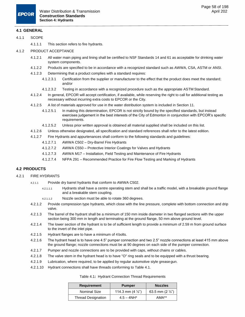
Page 58 of 198 Water Distribution & Transmission April 202 Construction Standards Section 4: Hydrants
4.1 GENERAL
4.1.1 SCOPE
4.1.1.1 This section refers to fire hydrants.
4.1.2 PRODUCT ACCEPTANCE
4.1.2.1 All water main piping and lining shall be certified to NSF Standards 14 and 61 as acceptable for drinking water
system components.
4.1.2.2 Products are specified to be in accordance with a recognized standard such as AWWA, CSA, ASTM or ANSI.
4.1.2.3 Determining that a product complies with a standard requires:
4.1.2.3.1 Certification from the supplier or manufacturer to the effect that the product does meet the standard;
and/or
4.1.2.3.2 Testing in accordance with a recognized procedure such as the appropriate ASTM Standard.
4.1.2.4 In general, EPCOR will accept certification, if available, while reserving the right to call for additional testing as
necessary without incurring extra costs to EPCOR or the City.
4.1.2.5 A list of materials approved for use in the water distribution system is included in Section 11.
4.1.2.5.1 In making this determination, EPCOR is not strictly bound by the specified standards, but instead
exercises judgement in the best interests of the City of Edmonton in conjunction with EPCOR’s specific
requirements.
4.1.2.5.2 Unless prior written approval is obtained all material supplied shall be included on this list.
4.1.2.6 Unless otherwise designated, all specification and standard references shall refer to the latest edition.
4.1.2.7 Fire Hydrants and appurtenances shall conform to the following standards and guidelines:
4.1.2.7.1 AWWA C502 – Dry-Barrel Fire Hydrants
4.1.2.7.2 AWWA C550 – Protective Interior Coatings for Valves and Hydrants
4.1.2.7.3 AWWA M17 – Installation, Field Testing and Maintenance of Fire Hydrants
4.1.2.7.4 NFPA 291 – Recommended Practice for Fire Flow Testing and Marking of Hydrants
4.2 PRODUCTS
4.2.1 FIRE HYDRANTS
4.2.1.1 Provide dry barrel hydrants that conform to AWWA C502.
4.2.1.1.1 Hydrants shall have a centre operating stem and shall be a traffic model, with a breakable ground flange
and a breakable stem coupling.
4.2.1.1.2 Nozzle section must be able to rotate 360 degrees.
4.2.1.2 Provide compression type hydrants, which close with the line pressure, complete with bottom connection and drip
valve.
4.2.1.3 The barrel of the hydrant shall be a minimum of 150 mm inside diameter in two flanged sections with the upper
section being 300 mm in length and terminating at the ground flange, 50 mm above ground level.
4.2.1.4 The lower section of the hydrant is to be of sufficient length to provide a minimum of 2.59 m from ground surface
to the invert of the inlet pipe.
4.2.1.5 Hydrant flanges are to have a minimum of 4 bolts.
4.2.1.6 The hydrant head is to have one 4.5” pumper connection and two 2.5” nozzle connections at least 415 mm above
the ground flange; nozzle connections must be at 90 degrees on each side of the pumper connection.
4.2.1.7 Pumper and nozzle connections are to be provided with caps, without chains or cables.
4.2.1.8 The valve stem in the hydrant head is to have "O" ring seals and to be equipped with a thrust bearing.
4.2.1.9 Lubrication, where required, to be applied by regular automotive style grease gun.
4.2.1.10 Hydrant connections shall have threads conforming to Table 4.1.
Table 4.1: Hydrant Connection Thread Requirements
Requirement Pumper Nozzles
Nominal Size 114.3 mm (4 ½”) 63.5 mm (2 ½”)
Thread Designation 4.5 – 4NH* AMA**

Page 59 of 198 Water Distribution & Transmission April 202 Construction Standards Section 4: Hydrants
*NH - American National Fire Protection hose connection screw threads **AMA - Alberta Mutual Aid thread.
4.2.1.11 Pumper and nozzle caps are to be threaded into the hydrant head, rather than leaded in, unless a positive locking
device is provided to prevent blow-out of the caps.
4.2.1.12 The operating nut on the hydrant valve stem and on the pumper and nozzle caps shall be 3 sided, each side
being an arc, with 1.5” between points (chord length) and 1.5” radius.
4.2.1.13 The hydrant valve, pumper and nozzle caps shall open counter-clockwise.
4.2.1.14 All external nuts and bolts, excluding ground flange, are to be Type 304 stainless steel or better.
4.2.1.15 Provide a bottom connection flanged to the barrel, with a single gasket, push-on type joint for ductile iron or PVC
pipe, 150 mm diameter only (cast iron outside diameter), complete with harnessing lugs.
4.2.1.16 Internal Paint
4.2.1.16.1 Hydrant body (internal top section) is to be painted to AWWA C502 and AWWA C550.
4.2.1.16.2 Alternatively internal surfaces may be left bare.
4.2.1.17 External Paint
4.2.1.17.1 Hydrant body (external top section) is to be painted to AWWA C502 - yellow or the following:
4.2.1.17.1.1 Primer – Benjamin Moore Industrial Maintenance Universal Metal Primer, White, or equivalent
4.2.1.17.1.2 Surface Coat – Benjamin Moore Alkyd Enamel Yellow, or approved equal, 1 coat.
4.2.1.17.2 Hydrant dome, both 2.5" nozzle caps, and 4.5" pumper cap are to be painted using Benjamin Moore
Industrial Maintenance Rapid Dry Gloss Alkyd Enamel or an approved equal in accordance with NFPA
291 standards, as shown in Table 4.2.
4.2.1.17.3 Hydrant numbers to be painted on back of hydrant in black or safety blue at least 300 mm above the
ground flange, preferably directly behind the 4.5" pumper cap.
4.2.1.17.3.1 Font to be 50 mm Arial.
4.2.1.17.4 Location of hydrant control valve is to be marked on hydrant showing distance of control valve from
hydrant in meters (e.g. 2.5).
4.2.1.17.4.1 Markings to be in direct alignment with valve.
4.2.1.17.4.2 Control valve location number is to be marked at 250 mm above ground flange or higher, font to be 50 mm Arial.
Table 4.2: Hydrant paint colours
Hydrant Flow Capacity Dome, Pumper and Nozzle Cap Colour
US gpm L/s
1500 or greater 95 or greater Benjamin Moore Safety Blue or Approved Equal
1000 – 1500 60 – 95 Benjamin Moore Safety Green or Approved Equal
500 – 1000 30 – 60 Benjamin Moore Safety Orange or Approved Equal
< 500 < 30 Benjamin Moore Safety Red or Approved Equal
4.3 EXECUTION
4.3.1 INSPECTION OF MATERIAL BEFORE INSTALLATION
4.3.1.1 Before unloading, inspect the general condition of load for adequacy of packing and bracing, any signs of shifting
and any signs of damage to materials; where the load has shifted badly and material appears significantly
damaged, reject the entire load.
4.3.1.2 While unloading check each hydrant for:
4.3.1.2.1 The required manufacturer’s markings;
4.3.1.2.2 The mark of the manufacturer’s testing agency;
4.3.1.2.3 Damage to joint ends or surfaces;
4.3.1.2.4 Damage to coating or lining; and
4.3.1.2.5 Other visually apparent damage.

Page 60 of 198 Water Distribution & Transmission April 202 Construction Standards Section 4: Hydrants
4.3.1.3 If EPCOR is supplying the materials, note all damage and defects in writing and submit a copy of the receiving
inspection report to EPCOR.
4.3.1.3.1 EPCOR or EPCOR’s supplier will replace rejected materials.
4.3.1.3.2 Unless the piece is rejected entirely, the Contractor shall repair damage and defects discovered at the
time of receiving.
4.3.1.3.3 All materials, once accepted by the Contractor, become the responsibility of the Contractor until EPCOR
accepts the installation.
4.3.1.4 If the Contractor is supplying the materials, note all damage and defects in writing and submit a copy of the
receiving inspection report to EPCOR.
4.3.1.4.1 Repair damages or defects and replace rejects.
4.3.1.5 The Contractor shall maintain a continuous file of all receiving inspection reports at the job site, to be accessible
for review by EPCOR.
4.3.1.6 The Contractor is responsible for the safe storage of materials after delivery and before installation and for
handling and transportation between the storage site and the final location.
4.3.1.7 Hydrants shall be kept drained and stored before installation in a manner protecting them from damage due to
freezing of trapped water.
4.3.1.8 Prior to installation, hydrants shall be stored in a manner that protects them from damage from the environment in
which they are stored.
4.3.1.9 Manufacturer’s recommendations for hydrant storage shall be adhered to.
4.3.1.10 Visually inspect all joint ends and surfaces for damage or defects immediately before installation and reject and
remove any unacceptable hydrants from site.
4.3.2 INSTALLING HYDRANTS
4.3.2.1 Install hydrants at the locations designated.
4.3.2.2 Support hydrant base on treated fir blocks or as designated on the construction drawings.
4.3.2.3 Construct concrete thrust blocks in conformance with Drawings WA-002-002, WA-002-007, WA-002-008a, WA-
002-008b, and WA-004-001 or as shown on the construction drawings.
4.3.2.3.1 Ensure interface between concrete thrust block and pipe/fittings is constructed in accordance with the
pipe/fitting’s manufacturer’s recommendations and requirements.
4.3.2.4 Install hydrants in accordance with Drawings WA-004-001 and AWWA M17.
4.3.2.5 Install protection posts in accordance with Drawing WA-004-003 as needed.
4.3.2.6 Provide a minimum of 0.3 m3 of washed gravel media (25 mm nominal single size washed rock) to allow
unobstructed draining of the hydrant.
4.3.2.6.1 Washed gravel media is to be covered with polythene sheet, minimum 0.15 mm (6 mils) thick, to
prevent infiltration of backfill materials.
4.3.2.7 All nonstandard depth of bury installations require approval from EPCOR Water Services.
4.3.2.8 Install hydrant plumb, with ground flange horizontal and true.
4.3.2.8.1 Do not cause the hydrant to move out of plumb or out of position while placing and compacting backfill.
4.3.2.9 Where the water table is above the hydrant drain, the hydrant drain ports may require plugging.
4.3.2.9.1 These hydrants must be clearly identified on the engineering drawings and as-built submission.
4.3.2.9.2 Hydrants with plugged drain ports must be pumped free of standing water after each use.
4.3.2.9.3 Hydrant drain ports shall be plugged with approved internal plugs as per manufacturer’s specifications.
4.3.2.10 Where specifically designated on the drawings or as directed by EPCOR, provide a joint harness consisting of tie
rods and clamps.
4.3.2.11 Install Hydrant Disks as specified on the approved engineering drawings.
4.3.2.12 For hydrants that are installed in concrete (e.g. sidewalks), install in accordance with Detail WA-003-019.
4.4 PROTECTION DURING ADJACENT CONSTRUCTION
4.4.1 Hording shall be installed per Drawing WA-004-004 when existing hydrants are located within an active construction zone.
END OF SECTION

Construction Standards
Section 5 Water Services
April 2021

Page 62 of 198 Water Distribution & Transmission April 2021 Construction Standards Section 5: Water Services
5.1 GENERAL
5.1.1 SCOPE
5.1.1.1 This section applies to water services from the water main to the property line as follows:
5.1.1.1.1 Service pipe 20 mm to 50 mm in diameter;
5.1.1.1.2 Brass fittings, and service boxes for 20 mm to 50 mm diameter services;
5.1.1.1.3 Service Saddles for 40 mm and 50 mm diameter services; and
5.1.1.1.4 Service pipe and fittings 100 mm in diameter and larger.
5.1.2 PRODUCT ACCEPTANCE
5.1.2.1 All water service piping, lining, fittings and valves shall be certified to NSF Standards 14 and 61 as acceptable for
drinking water system components.
5.1.2.2 Products are specified to be in accordance with a recognized standard such as AWWA, CSA, ASTM or ANSI.
5.1.2.3 Determining that a product complies with a standard requires certification from the supplier or manufacturer to the
effect that the product does meet the standard or testing in accordance with a recognized procedure such as the
appropriate ASTM Standard.
5.1.2.4 In general EPCOR will accept certification, if available, while reserving the right to call for additional testing as
necessary without incurring extra costs to EPCOR or the City.
5.1.2.5 A list of material approved for use in the water distribution system is included as Section 11.
5.1.2.5.1 In making this determination, EPCOR is not strictly bound by the specified standards, but instead
exercises judgement in the best interests of the City of Edmonton in conjunction with EPCOR’s specific
requirements.
5.1.2.5.2 Unless prior written approval is obtained, only materials that appear on this list shall be supplied.
5.1.2.6 Unless otherwise designated, all specification and standard references shall refer to the latest edition.
5.1.3 STANDARDS
5.1.3.1 Water services and appurtenances shall conform to all applicable standards, including but not limited to the
following:
5.1.3.1.1 AWWA C800 – Underground Service Line Valves and Fittings.
5.1.3.1.2 AWWA C903 – Polyethylene—Aluminum—Polyethylene & Cross-linked Polyethylene— Aluminum—
Cross-Linked Polyethylene Composite Pressure Pipes, ½ In. (12 mm) Through 2 In. (50 mm), for Water
Service
5.1.3.1.3 ASTM B88 – Standard Specification for Seamless Copper Water Tube
5.1.3.1.4 ASTM B62 – Standard Specification for Composition Bronze or Ounce Metal Castings
5.1.3.1.5 ASTM B584 – Standard Specification for Copper Alloy Sand Castings for General Applications
5.1.3.1.6 CSA B137.5 – Cross-linked Polyethylene (PEX) Tubing Systems for Pressure Applications
5.1.3.1.7 CSA B137.1 - Polyethylene (PE) Pipe, Tubing and Fittings for Cold-Water Pressure Services
5.1.3.1.8 National Sanitation Foundation (NSF) Standard 14 - Plastics Piping System Components and Related
Materials
5.1.3.1.9 National Sanitation Foundation (NSF) Standard 61 - Drinking Water System Components: Health Effects
5.1.4 REGULATIONS
5.1.4.1 All applicable regulations shall be adhered to, including but not limited to the following:
5.1.4.1.1 City of Edmonton Water Services and Wastewater Treatment Bylaw 15816
5.1.4.1.2 City of Edmonton Sewers Bylaw 9425
5.1.4.1.3 City of Edmonton Sewers Use Bylaw 9675
5.1.4.1.4 City of Edmonton Surface Drainage Bylaw 11501
5.1.4.1.5 The Standards and Guidelines for Municipal Waterworks, Wastewater and Storm Drainage Systems -
Alberta Environment and Sustainable Resource Development (Alberta Environment and Parks as of
2015)
5.1.4.1.6 City of Edmonton Regulation of Work and Equipment Installation Bylaw 12846
5.1.4.1.7 Alberta Environmental Protection and Enhancement Act and associated Regulations
5.1.4.1.8 National Building Code of Canada

Page 63 of 198 Water Distribution & Transmission April 2021 Construction Standards Section 5: Water Services
5.1.4.1.9 Alberta Building Code
5.1.4.1.10 National Plumbing Code of Canada
5.1.4.1.11 National Fire Code of Canada
5.1.4.1.12 Alberta Fire Code
5.1.4.2 All products shall be installed in accordance with the recommended installation procedures provided by the
manufacturer.
5.2 PRODUCTS
5.2.1 COPPER SERVICE PIPE
5.2.1.1 Conform to AWWA C800, Type K copper pipe to ASTM B88.
5.2.1.2 Provide third party certification with the symbol of the certifier permanently marked at 0.5 m intervals on all
certified tubing.
5.2.1.2.1 The third party certifier shall be an accredited certification agency recognized by the Standards Council
of Canada.
5.2.1.3 Copper service pipe can be used for services 20 mm to 50 mm in diameter.
5.2.2 FITTINGS FOR COPPER SERVICE PIPE
5.2.2.1 Provide main stops, curb cocks, service boxes and couplings listed in Section 11 and according to AWWA C800.
5.2.2.2 All fittings to withstand a test pressure of 1035 kPa.
5.2.2.3 Provide service boxes per Drawings WA-005-003, WA-005-004, WA-005-005, and WA-005-006.
5.2.3 ALTERNATE SERVICE PIPE
5.2.3.1 Provide alternate service pipe according to Section 11.
5.2.3.2 Composite PE-Al-PE can be used for services 20 mm and 25 mm in diameter.
5.2.3.3 Cross linked PE can be used for services 20 mm to 50 mm nominal diameter.
5.2.3.4 Sizing is by internal diameter.
5.2.4 FITTINGS FOR ALTERNATE SERVICE PIPE
5.2.4.1 Provide main stops, curb cocks, service boxes and couplings according to Section 11 and AWWA C800.
5.2.4.2 All fittings to withstand a test pressure of 1035 kPa.
5.2.4.3 Provide service boxes, as per Drawings WA-005-003, WA-005-004, WA-005-005, and WA-005-006.
5.2.5 LARGE SERVICE PIPE AND FITTINGS
5.2.5.1 Large Service means sizes 100 mm nominal diameter and larger.
5.2.5.2 Generally use the same materials of service pipe, fittings, and valves as the distribution main pipe.
5.2.5.3 Provide valve boxes per Drawings WA-003-001 to WA-003-009.
5.2.6 SERVICE SADDLES
5.2.6.1 To be of stainless steel Type 304 and/or bronze construction.
5.2.6.2 Bronze components shall be Waterworks Bronze (85-5-5-5) in conformance with ASTM B62.
5.2.6.3 Single or double band design with a minimum total band width of 90 mm.
5.2.6.4 Nuts and bolts to be Type 304 stainless steel with threads treated to prevent binding.
5.2.6.5 Gaskets shall be of synthetic rubber suitable for potable water use.
5.2.6.6 Use for all pipe types except steel and concrete cylinder pipe.
5.2.7 SERVICE RODS
5.2.7.1 Operating rods for 20mm and 25 mm curb cocks shall be Type 304 stainless steel. The rod shall be attached to a
manganese bronze or stainless steel clevis with a stainless steel rivet. Refer to Drawing WA-005-003 and WA-
005-004.
5.2.7.2 Operating rods for 40mm and 50 mm curb cocks shall be mild steel. Refer to Drawings WA-005-005 and WA-005-
006.
5.2.7.3 One stainless steel or brass cotter pin shall be supplied with each operating rod (packaged separately).
5.2.7.4 Table 5.1 shows alternative material specifications that shall apply for each component.

Page 64 of 198 Water Distribution & Transmission April 2021 Construction Standards Section 5: Water Services
Table 5.1: Material specifications for service rods
Component Specification Type of Alloy UNIS No. Composition (%) Minimum Yield Strength (MPa)
Stainless Steel Rod, Rivet and Cotter Pin
AISI 304
C, 0.08 max.
242
Cr, 18.0 to 20.0 Ni, 8.0 to 10.0 Mn, 2.0 max. Si, 1.0 max. P, 0.045 max. S, 0.03 max.
Manganese Bronze Clevis
ASTM B584
C86200
Al, 3.0 to 4.9
310
Cu, 60 to 66 Fe, 2.0 to 4.0 Mn, 2.5 to 5.0 Ni, 1.0 Max Pb, 0.2 Max. Sn, 0.2 Max.
Zn, 22.0 to 28.0
C86300
Al, 5.0 to 7.5
414
Cu, 60 to 66 Fe, 2.0 to 4.0 Mn, 2.5 to 5.0 Ni, 1.0 Max. Pb, 0.2 Max. Sn, 0.2 Max. Zn, 22.0 to 28.0
5.3 EXECUTION
5.3.1 INSPECTION OF MATERIAL BEFORE INSTALLATION
5.3.1.1 Inspect the general condition of load for adequacy of packing and bracing, any signs of shifting and any signs of
damage to materials before unloading materials.
5.3.1.1.1 Reject the entire load where the load has shifted badly and material appears significantly damaged.
5.3.1.2 While unloading check each piece of pipe and/or each fitting for:
5.3.1.2.1 The required manufacturers’ markings;
5.3.1.2.2 The mark of the manufacturer’s testing agency;
5.3.1.2.3 Damage to joint ends or surfaces;
5.3.1.2.4 Damage to coating or lining; and
5.3.1.2.5 Other visually apparent damage.
5.3.1.3 If EPCOR is supplying the materials, note all damage and defects in writing and submit a copy of the receiving
inspection report to EPCOR.
5.3.1.3.1 All materials, once accepted, become the responsibility of the Contractor until EPCOR accepts the
installation.
5.3.1.3.2 Unless the piece is rejected entirely, the Contractor shall repair damage and defects discovered at the
time of receiving.
5.3.1.3.3 Rejected materials are to be replaced by EPCOR or EPCOR’s supplier.
5.3.1.4 If the Contractor is supplying the materials, note all damage and defects in writing and submit a copy of the
receiving inspection report to EPCOR.
5.3.1.4.1 Repair damages or defects, and replace rejects.
5.3.1.5 Maintain a continuous file of all receiving inspection reports at the job-site. Allow EPCOR access to these reports
for review.
5.3.1.6 The Contractor is responsible for:
5.3.1.6.1 The safe storage of materials after delivery and before installation; and

Page 65 of 198 Water Distribution & Transmission April 2021 Construction Standards Section 5: Water Services
5.3.1.6.2 Handling and transporting between the storage site and the final location.
5.3.1.7 Visually inspect all joint ends and surfaces for damage or defects immediately before installation.
5.3.1.7.1 Reject and remove any unacceptable pipe or fittings from the site.
5.3.1.8 Check brass water service fittings for damaged end threads before installation.
5.3.2 WATER SERVICES
5.3.2.1 Tap other pipe materials in accordance with Section 10 and in accordance with the instructions of the tapping
equipment supplier for the specific pipe material.
5.3.2.2 Carefully and evenly support exposed sections of water main pipe during tapping operations and carefully restore
the pipe bedding to provide even support on completion.
5.3.2.3 Existing water mains shall not be subjected to excessive point loadings, deflection, rotation or displacement, at
any time during the construction process.
5.3.2.4 Where Asbestos Cement water main pipe is encountered, extra caution is required.
5.3.2.5 Review plans and procedures on site with the EPCOR Inspector.
5.3.2.6 Curb cock shall be located 0.1 m from the property line, on the city side, except for lots serviced from the side,
where curb cocks must be 0.3 m from the property line, on the city side. Ensure that the curb cock is installed in
the proper direction. Alternative curb cock locations must be shown on the engineering drawings and must be
approved by the Engineer, EPCOR Water Services.
5.3.2.6.1 Water drops shall be stamped into the sidewalk in front of each lot’s curb cock with the tip of the drop
pointing in the direction of the curb cock (see Drawing WA-005-013).
5.3.2.7 The invert of the service pipe shall be at 2.7 +/- 0.15 m below finished grade at the curb cock, except in freeze
zones where the invert of the service pipe shall be at 2.89 m below finished grade at the property line. The top of
the control rod is to be at 1.50 m +/- 0.15 m below finished grade regardless of the depth of bury. The freeze
zones are defined in Section 1.6.2.2.
5.3.2.8 All curb cocks installed on water service connections to properties shall be of the non-bleeder (not self-draining)
type unless specifically approved.
5.3.2.8.1 Self-draining (bleeder type) curb cocks will be installed only on seasonal water services with prior written
approval on a project specific basis.
5.3.2.9 Valves for large services shall be installed by TVS in accordance with Section 10 or strapped to tee in
accordance with Drawing WA-003-009.
5.3.2.10 Water and sewer services shall be extended into property beyond the gas URW in accordance with Drawing WA-
005-007.
5.3.2.11 Minimum size of water service shall be as shown in Table 5.2.
Table 5.2: Minimum water service sizes
Class of Building Minimum Service Size – Internal Diameter
Single-Family Dwelling 25 mm
Multi-Family Dwelling (one titled lot) 40 mm or 25 mm service to each unit*
Multi-Family Dwelling (separately titled fee simple lots) 25 mm service to each lot
*If fronting public road right-of-way. Refer to Drawings WA-005-011a and WA-005-011b.
5.3.2.12 A larger service size than that which is indicated in Table 5.2 will be required where the length of the service pipe,
the potential demand, the supply pressure or other conditions warrant a mandated increase. For non-residential
buildings install water services as designated by EPCOR Water Services or as shown on the drawings.
5.3.2.12.1 If the length of the water service from the mainstop to property line is greater than 20 m, the service
must be increased to next standard service size.
5.3.2.13 For services 100 mm and larger use the same material systems as the distribution mains to which they are
connected.
5.3.2.14 Do not install services sized between 50 mm and 100 mm in diameter.
5.3.2.15 Provide a “goose-neck” at each mainstop in accordance with Drawings WA-005-001 and WA-005-002.
5.3.2.15.1 Provide an additional “goose-neck” at each sewer crossing.
5.3.2.15.2 Avoid kinking or crimping the water service tubing.

Page 66 of 198 Water Distribution & Transmission April 2021 Construction Standards Section 5: Water Services
5.3.2.15.3 Bend to minimum 300 mm radius or to manufacturer’s specification, whichever is greater.
5.3.2.15.4 Support and protect service tubing to prevent damage or displacement.
5.3.2.15.5 Vertical goosenecks shall only be used with prior written approval by the Engineer and must be insulated
per Drawing WA-002-001.
5.3.2.16 Install a service box or valve casing in accordance with Drawings WA-005-003, WA-005-004, WA-005-005, WA-
005-006 or WA-003-001 to WA-003-008.
5.3.2.16.1 Set vertically and brace to remain vertical during backfilling and compaction.
5.3.2.16.2 For small services, set the top of service box below grade at sufficient depth to avoid damage during the
maintenance period.
5.3.2.16.3 The contractor shall raise the top section to finished grade prior to requesting FAC inspection.
5.3.2.17 Install dual services in one trench in accordance with Drawing WA-005-007.
5.3.2.18 All service pipes are to be in one continuous piece.
5.3.2.18.1 Use couplings only when the service pipe exceeds the length of a standard roll of service tubing.
5.3.2.18.2 Locate double unions outside of paved areas if possible, usually in the boulevard.
5.3.2.19 Allow at least 600 mm between mainstops.
5.3.2.20 No mainstop shall be within 600 mm of a bell, coupling or collar.
5.3.2.21 Backfill around curb cock and casing bottom section with clay, not with granular material.
5.3.2.22 Test water services in accordance with Section 8.
5.3.2.23 Where the water service is 50 mm diameter or smaller, install it in the same trench as the sewer services and to
the right of the sanitary sewer service when facing towards the property being served. Refer to Drawings WA-
005-007 and WA-005-008, sewer bylaws and water bylaw.
5.3.2.24 Where the water service is 100 mm diameter or larger, install it in a separate trench at least 2.5 m from any
sewer, in accordance with sewer and water bylaws, and 1.8 m from gas or power lines.
5.3.2.25 Install services in accordance with all applicable Drawings (WA-005-001 to WA-005-012) unless indicated
otherwise on the construction drawings.
5.3.3 SERVICES INSTALLED BY AUGERING, BORING OR TUNNELLING
5.3.3.1 Auger, bore or tunnel under existing sidewalks, curb and gutter, etc.
5.3.3.2 For augering, boring or tunneling, refer to applicable Sections in the City of Edmonton Design and Construction
Standards Volume 3, Drainage, including 02445 Bored Undercrossing, 02441 Microtunnelling, and 02446
Horizontal Directional Drilling.
5.3.3.3 Install water, sanitary and storm sewer service pipe.
5.3.3.4 If the service is installed in a tunnel, place and hand tamp Class B bedding to fill tunnel cross- section; if the
service is installed by augering or boring, fill the auger or bore hole with a dry or slurry mixture of sand/cement.
5.3.4 RECORD OF SERVICES
5.3.4.1 All service information must be submitted according to Section 1.4.6.2.
5.3.4.2 As-built survey data must include the following:
5.3.4.2.1 Main stop;
5.3.4.2.2 Curb stop;
5.3.4.2.3 End of pipe;
5.3.4.2.4 Any couplings; and
5.3.4.2.5 Any pipe deviations.
5.3.4.3 Obtain the approved method of delivering as-built information from Water and Sewer Services (WASS), showing
locations related to property lines and street and avenue designations, coordinates and elevations of curb cocks
(CC) and valves, main stops, and pipe sizes/lengths/materials.
5.3.4.3.1 Complete required information in accordance with WASS’ instructions.
5.3.4.3.2 For further information, contact (780) 496-5444 or [email protected].
5.3.4.4 The above as-built information must be provided for any lots pre-serviced as part of a project.

Page 67 of 198 Water Distribution & Transmission April 2021 Construction Standards Section 5: Water Services
5.3.5 REPLACEMENT AND/OR RECONNECTION OF EXISTING WATER SERVICES
5.3.5.1 Replace services with approved water service materials, from the main to the property line, including service
valves.
5.3.5.2 Additional information on obtaining a new water service is available from EPCOR’s Water Services Guidelines,
available on the EPCOR Website.
5.3.5.3 Replace any part of an existing service exposed during construction that is found to be in poor condition.
5.3.5.3.1 Extent of replacement to be as directed by EPCOR.
5.3.5.3.2 The charges for this extra work shall be consistent with the unit prices quoted in the Contractor’s bid,
and subject to EPCOR’s approval.
5.3.5.4 Replace all existing water services and curb stops that service properties on the side of the lane closest to the
water main when the water main is replaced.
5.3.5.5 All water services encountered during construction shall be reconnected to the new water main.
5.3.5.5.1 If a water service that is not identified on the drawings is encountered, obtain written authorization from
EPCOR prior to connecting it to the new water main.
5.3.5.6 Where a water service to two or more properties is provided by a single water service line and is encountered
during construction, it is to be replaced with individual water service pipes for each property from the property line
to the water main.
5.3.6 CATHODIC PROTECTION
5.3.6.1 Install cathodic protection for metallic components of water services in accordance with Section 7.
5.3.6.2 Install sacrificial anodes on all existing and replaced copper services in accordance with Section 7 and Drawing
WA-005-001 and WA-007-006.
5.3.7 REPLACEMENT OF EXISTING CURB COCKS
5.3.7.1 All faulty curb cocks, as identified during pre-construction inspection, will be replaced with new curb cocks.
5.3.7.2 If the new curb cock is to be reconnected to an existing copper service piping less than 1.5 m long, the
copper service piping will be replaced in its entirety together with the installation of the new curb cock.
5.3.8 TURNING ON SERVICES
5.3.8.1 Do not operate any service control valves unless specifically authorized to do so.
5.3.8.1.1 Only EPCOR Water Services Distribution Operations personnel or contractual agents, either under direct
supervision of or with prior approval from EPCOR Water Services, can operate services.
5.3.8.2 Work with EPCOR Water Services Distribution Operations personnel to maintain a watch in case a leak develops
on those services utilized within 3 days of bringing a new water main into operation.
5.3.8.3 Be prepared to deal promptly with a service leak.
5.3.8.4 Be prepared to perform additional water sampling and testing in the event that water quality concerns arise.
5.3.8.5 Dechlorinate discharges of chlorinated water as required under federal law and local bylaws.
5.3.8.6 Additional information on turning on water services and obtaining a new water service is available from EPCOR’s
Water Services Guidelines, available on the EPCOR Website.
END OF SECTION

Construction Standards
Section 6 Pipe Bedding
April 2021

Page 69 of 198 Water Distribution & Transmission April 2021 Construction Standards Section 6: Pipe Bedding
6.1 GENERAL
6.1.1 SCOPE
6.1.1.1 This section covers bedding and structural support for water pipe in excavations and all material under and
around the pipe to 300 mm above the top-of-pipe.
6.1.2 ASSOCIATED WORK
6.1.2.1 Trench and backfill shall be undertaken in accordance with the City of Edmonton Design and Construction
Standards Volume 2: Roadways, Section 3.1 – Trench and Backfill.
6.1.2.2 Utility cut restoration shall be undertaken in accordance with the City of Edmonton Design and Construction
Standards Volume 2: Roadways, Section 3.2 – Utility Cut Restoration.
6.1.2.3 Fillcrete backfill shall be undertaken in accordance with the City of Edmonton Design and Construction Standards
Volume 2: Roadways, Section 7.11 – Fillcrete.
6.2 PRODUCTS
6.2.1 PIPE BEDDING MATERIAL
6.2.1.1 Fine Granular: Provide granular material clean and free of organic matter, pit-run or crushed within the gradation
limits shown in Table 6.1.
Table 6.1: Gradation limits for fine granular
Sieve Size (mm) Percent Passing by Mass
10.000 100
5.000 70 to 100
0.150 5 to 20
0.075 0 to 12
6.2.1.2 Coarse Granular: Provide granular material clean and free of organic matter, pit-run or crushed within the
gradation limits shown in Table 6.2.
Table 6.2: Gradation limits for coarse granular
Sieve Size (mm) Percent Passing by Mass
25.000 100
20.000 95 to 100
10.000 60 to 80
5.000 40 to 60
0.150 5 to 15
6.2.1.3 Washed Gravel: Washed, crushed or screened, stone or gravel consisting of hard and durable particles, meeting
the gradation limits in Table 6.3, and free from sand, clay, cementitious, organic and other deleterious material.
Table 6.3: Gradation limits for washed gravel
Sieve Size (mm) Percent Passing by Mass
25.00 100
5.00 10 max
0.08 2 max
6.2.1.4 Use washed gravel only if approved by EPCOR.
6.3 EXECUTION
6.3.1 CLASSES OF TRENCH BEDDING
6.3.1.1 Use the class of bedding specified on the construction drawings. If there is no specific designation, use Class B
bedding, with fine granular bedding material. Refer to Drawing WA-006-001.

Page 70 of 198 Water Distribution & Transmission April 2021 Construction Standards Section 6: Pipe Bedding
6.3.1.1.1 Class A – Place a cradle of plain concrete or reinforced concrete, minimum 15 MPa, under the pipe,
across the entire width of the trench, and along the sides of the pipe to provide a support angle of 120°.
Place and compact fine granular bedding material above the concrete to 300 mm above the top- of-pipe.
Compact to 95% of Standard Proctor Density.
6.3.1.1.2 Class B – Place and compact 75 mm (minimum depth) of fine granular bedding material under the pipe
(maximum depth 400 mm) and around the pipe to 300 mm above the top-of-pipe. Compact to 95% of
Standard Proctor Density.
6.3.1.1.3 Class C – Place and compact 75 mm (minimum depth) of fine granular bedding material under the pipe
(maximum depth 400 mm) and around sides of the pipe up to the spring line. Compact to 95% of
Standard Proctor Density. Place and compact suitable backfill material from the spring line to 300 mm
above the top-of-pipe. Compact to 95% of Standard Proctor Density.
6.3.1.1.4 Class D – Shape the bottom of the trench to fit the pipe over a 90º support angle. Place and compact
suitable backfill material around the pipe to 300 mm above the top-of-pipe. Compact to 95% of Standard
Proctor Density.
6.3.1.2 All bedding and backfill material is to be placed in 150 mm layers and compacted.
6.3.1.3 For pipes larger than 450 mm, with Class A, B, or C bedding, place and compact 1.0 m long clay cut- off walls to
an undisturbed bottom across the entire trench at intervals of 150 m.
6.3.2 BEDDING FOR PIPE IN EXCAVATIONS FOR STRUCTURES
6.3.2.1 Where the depth from the underside of the pipe to solid, undisturbed ground is less the 0.5 m, place and compact
fine granular bedding material under and around the pipe to 300 mm above the top-of- pipe, extending across the
entire width of the excavation to the undisturbed wall of the excavation. Compact to 95% of Standard Proctor
Density
6.3.2.2 If the depth to undisturbed ground is between 0.5 m and 1.0 m, place suitable material below the pipe bedding
zone. Place in 150 mm layers and compact to 95% of Standard Proctor Density.
6.3.2.3 Where the depth from the underside of pipe to undisturbed, solid, ground is greater than 1.0 m, provide structural
support as shown on the drawings or as directed by EPCOR.
6.3.2.4 If there is over-excavation beyond the specified limits, advise EPCOR and obtain instructions.
END OF SECTION

Construction Standards
Section 7 Cathodic Protection
April 2021
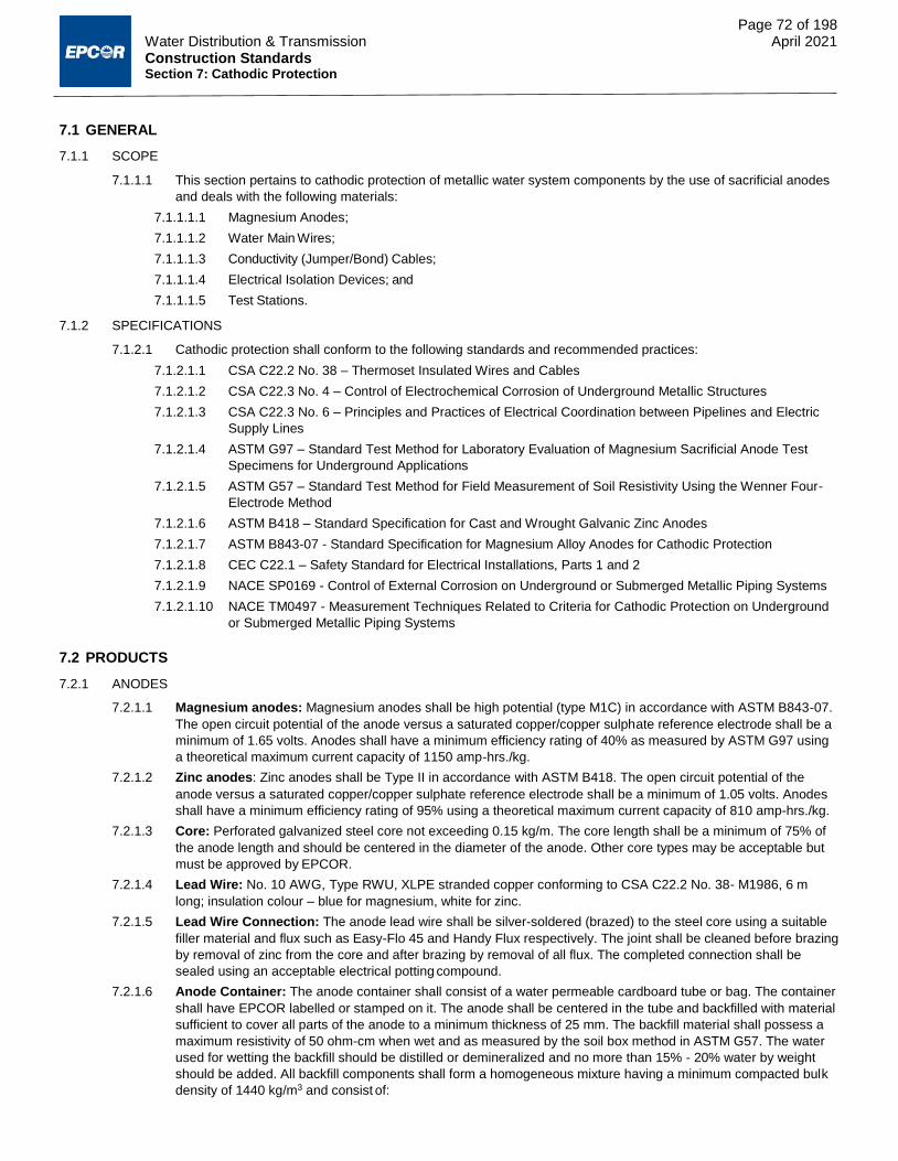
Page 72 of 198 Water Distribution & Transmission April 2021 Construction Standards Section 7: Cathodic Protection
7.1 GENERAL
7.1.1 SCOPE
7.1.1.1 This section pertains to cathodic protection of metallic water system components by the use of sacrificial anodes
and deals with the following materials:
7.1.1.1.1 Magnesium Anodes;
7.1.1.1.2 Water Main Wires;
7.1.1.1.3 Conductivity (Jumper/Bond) Cables;
7.1.1.1.4 Electrical Isolation Devices; and
7.1.1.1.5 Test Stations.
7.1.2 SPECIFICATIONS
7.1.2.1 Cathodic protection shall conform to the following standards and recommended practices:
7.1.2.1.1 CSA C22.2 No. 38 – Thermoset Insulated Wires and Cables
7.1.2.1.2 CSA C22.3 No. 4 – Control of Electrochemical Corrosion of Underground Metallic Structures
7.1.2.1.3 CSA C22.3 No. 6 – Principles and Practices of Electrical Coordination between Pipelines and Electric
Supply Lines
7.1.2.1.4 ASTM G97 – Standard Test Method for Laboratory Evaluation of Magnesium Sacrificial Anode Test
Specimens for Underground Applications
7.1.2.1.5 ASTM G57 – Standard Test Method for Field Measurement of Soil Resistivity Using the Wenner Four-
Electrode Method
7.1.2.1.6 ASTM B418 – Standard Specification for Cast and Wrought Galvanic Zinc Anodes
7.1.2.1.7 ASTM B843-07 - Standard Specification for Magnesium Alloy Anodes for Cathodic Protection
7.1.2.1.8 CEC C22.1 – Safety Standard for Electrical Installations, Parts 1 and 2
7.1.2.1.9 NACE SP0169 - Control of External Corrosion on Underground or Submerged Metallic Piping Systems
7.1.2.1.10 NACE TM0497 - Measurement Techniques Related to Criteria for Cathodic Protection on Underground
or Submerged Metallic Piping Systems
7.2 PRODUCTS
7.2.1 ANODES
7.2.1.1 Magnesium anodes: Magnesium anodes shall be high potential (type M1C) in accordance with ASTM B843-07.
The open circuit potential of the anode versus a saturated copper/copper sulphate reference electrode shall be a
minimum of 1.65 volts. Anodes shall have a minimum efficiency rating of 40% as measured by ASTM G97 using
a theoretical maximum current capacity of 1150 amp-hrs./kg.
7.2.1.2 Zinc anodes: Zinc anodes shall be Type II in accordance with ASTM B418. The open circuit potential of the
anode versus a saturated copper/copper sulphate reference electrode shall be a minimum of 1.05 volts. Anodes
shall have a minimum efficiency rating of 95% using a theoretical maximum current capacity of 810 amp-hrs./kg.
7.2.1.3 Core: Perforated galvanized steel core not exceeding 0.15 kg/m. The core length shall be a minimum of 75% of
the anode length and should be centered in the diameter of the anode. Other core types may be acceptable but
must be approved by EPCOR.
7.2.1.4 Lead Wire: No. 10 AWG, Type RWU, XLPE stranded copper conforming to CSA C22.2 No. 38- M1986, 6 m
long; insulation colour – blue for magnesium, white for zinc.
7.2.1.5 Lead Wire Connection: The anode lead wire shall be silver-soldered (brazed) to the steel core using a suitable
filler material and flux such as Easy-Flo 45 and Handy Flux respectively. The joint shall be cleaned before brazing
by removal of zinc from the core and after brazing by removal of all flux. The completed connection shall be
sealed using an acceptable electrical potting compound.
7.2.1.6 Anode Container: The anode container shall consist of a water permeable cardboard tube or bag. The container
shall have EPCOR labelled or stamped on it. The anode shall be centered in the tube and backfilled with material
sufficient to cover all parts of the anode to a minimum thickness of 25 mm. The backfill material shall possess a
maximum resistivity of 50 ohm-cm when wet and as measured by the soil box method in ASTM G57. The water
used for wetting the backfill should be distilled or demineralized and no more than 15% - 20% water by weight
should be added. All backfill components shall form a homogeneous mixture having a minimum compacted bulk
density of 1440 kg/m3 and consist of:

Page 73 of 198 Water Distribution & Transmission April 2021 Construction Standards Section 7: Cathodic Protection
7.2.1.6.1 Ground Hydrated Gypsum 75%
7.2.1.6.2 Powdered Wyoming Bentonite 20%
7.2.1.6.3 Anhydrous Sodium Sulphate 5%
7.2.1.7 Shipping Container: All anodes shall be shipped in watertight plastic bags. Anodes shall carry a label identifying
the casting manufacturer, packaging company, anode metal, anode weight, date packaged and supplier
reference number.
7.2.1.8 Supply magnesium and zinc anodes in the sizes shown on the drawings.
7.2.2 WIRES
7.2.2.1 Water Main Structure and Test Lead Wires
7.2.2.1.1 Unless otherwise indicated on the drawings, water main structure and test lead wires used at test
stations (Drawing WA-007-001) shall be No. 8 AWG for structure lead or No. 12 AWG for test lead, type
RWU, XLPE, stranded copper conforming to CSA C22.2 No. 38 - M1986; length as designated on the
drawings or as required under Section 7.5.6, colour - black.
7.2.2.2 Anode Header Cables and Anode Lead Wires
7.2.2.2.1 Unless otherwise indicated on the drawings, anode header cables (on which rows of anodes are spliced
and routed to the test station) shall be No. 8 AWG, type RWU, XLPE, stranded copper conforming to
CSA C22.2 No. 38-M1986; length as required on the drawings, colour – blue for magnesium, white for
zinc.
7.2.2.3 Conductivity (Jumper/Bond) Cables
7.2.2.3.1 Unless otherwise indicated on the drawings, jumper cables used for bonding across couplings, valves,
etc. shall be No. 8 AWG, type RWU, XLPE, stranded copper conforming to CSA C22.2 No.38 - M1986;
length as designated on the drawings or as required under Section 7.5.8, jumper/bond cable colour –
red.
7.2.3 ELECTRICAL ISOLATION DEVICES
7.2.3.1 Where it is deemed necessary to electrically isolate one section of main from another, electrical isolation devices
such as a 600 mm long piece of PVC pipe, an isolation coupling or an isolation flange kit should be installed.
7.2.3.2 Isolation couplings shall be Romac style IC501, IC400, Smith-Blair Style 416 or an approved equal
7.2.3.3 Flange isolation kits shall have full faced, plain face phenolic gaskets and polyethylene sleeves and washers. Use
Advance Products and Systems kits or approved equal.
7.2.4 TEST STATIONS
7.2.4.1 Unless otherwise designated on the drawings, test stations shall be in accordance with Drawings WA-003-001 to
WA-003-008 inclusive, WA-007-001, WA-007-005 and WA-007-008.
7.2.4.2 The test station wiring configuration shall be in accordance with Drawings WA-007-001 and WA-007-008.
7.3 EXECUTION
7.3.1 GENERAL
7.3.1.1 Provide cathodic protection for steel, cast and ductile iron pipe, cast iron fittings, valves, hydrants, copper
services, and where shown on the drawings.
7.3.1.2 Cathodic protection including anode location, size and spacing must be in accordance with the construction
drawings and Drawings WA-007-001 to WA-007-008.
7.3.2 ANODES
7.3.2.1 Install anodes as shown on the drawings using an auger, hydrovac or backhoe if required, to achieve the
specified bury depth.
7.3.2.2 Remove any plastic covers from anodes before installing.
7.3.2.3 Diameter of vertically drilled anode holes is to be 25 mm larger than the anode diameter. Pack original excavated
soil firmly around anodes to eliminate air pockets, where possible.
7.3.2.4 For vertically installed anodes and remote main attachment, use a remote stud-welding procedure approved by
EPCOR.
7.3.2.5 Extend anode wire for anodes connected to water mains along the main to the test station, taping the wires
together at 1 m intervals.

Page 74 of 198 Water Distribution & Transmission April 2021 Construction Standards Section 7: Cathodic Protection
7.3.3 WATER MAIN WIRES
7.3.3.1 At a test station location, exothermic weld (ex. cadweld or thermoweld) using the appropriate moulds and
sleeves, stud weld, or pin braze two separate water main wires to the crown of the water main, 300 mm apart.
7.3.3.1.1 Where possible, wrap lead wires around the pipe to reduce strain on the weld connection.
7.3.3.2 Protect each weld area from corrosion by the use of either:
7.3.3.2.1 Royston Roybond 747 primer and Handy Cap IP;
7.3.3.2.2 Polyken 1027 primer and three layers of Polyken 931 filler tape; or
7.3.3.2.3 Polyguard 600, KEMA 250-12 and KEMA 250 (contact manufacturer for application instructions and ensure
personnel has the appropriate qualifications).
7.3.4 ANODE HEADER CABLES AND ANODE LEAD WIRES
7.3.4.1 Trench header cables at the depth indicated on the drawings.
7.3.4.1.1 Trim excess cable at each end past the point where the last anode wire has been attached.
7.3.4.1.2 Install cables relatively straight - avoid excessive “snaking“.
7.3.4.2 Install anode lead wires as designated on the drawings. Lead wires enclosed in PVC conduit shall conform to the
requirements as shown in Table 7.1.
Table 7.1: Requirements for anode lead wires in PVC conduit
Wire Number & Type per Conduit
Conduit Size Required (mm)
2 - #6 25
4 - #6 30
8 - #6 40
8 - #6 & 4 - #12 50
7.3.4.3 Conduits for lead wires shall conform to CSA C22.2.
7.3.4.4 Splices in conduit shall not be allowed.
7.3.4.5 Connect header cables, anode lead wires and anode wires by the methods stated in Section 7.5.5.
7.3.5 SPLICES & CONNECTIONS
7.3.5.1 Connections to the structure or pipe being cathodically protected shall be made by one of the following methods:
7.3.5.1.1 Exothermic weld (cadweld or thermoweld);
7.3.5.1.2 Pin brazing; or
7.3.5.1.3 Stud welding.
7.3.5.2 Splices in cables or wires to connect anodes to header cables or extend leads shall be completed by one of the
following methods:
7.3.5.2.1 Exothermic weld (cadweld or thermoweld) using the appropriate mould and sleeve;
7.3.5.2.2 Crimp type connectors as manufactured by Burndy, T&B, or equivalent;
7.3.5.2.3 Servit or split-bolt type connectors as manufactured by Burndy, T&B or equivalent; or
7.3.5.2.4 Soldering the wires using a 60/40 lead-tin resin core solder.
7.3.5.3 Protect each splice from corrosion by using one of the following methods:
7.3.5.3.1 3M 8420 Series Cold Shrink Connector (for anode wires only);
7.3.5.3.2 One layer of 3M Scotchfill putty;

Page 75 of 198 Water Distribution & Transmission April 2021 Construction Standards Section 7: Cathodic Protection
7.3.5.3.3 Two layers of 3M Scotch 130C Linerless Rubber Splicing Tape and two layers of 3M Super 33+ Vinyl
Plastic Electrical Tape; or
7.3.5.3.4 Raychem WCSM - 9/3 heat shrink sleeve.
7.3.6 TEST STATIONS
7.3.6.1 Unless otherwise indicated on the drawings, install test stations in accordance with Drawing WA-007-001.
7.3.6.2 Test stations backfilled with granular material or fillcrete shall conform to the requirements of Drawing WA-007-
008.
7.3.6.3 Extend separate anode/anode lead and water main wires through casing.
7.3.6.4 Fill test station casing with sand to within 400 mm of grade and provide a minimum of 1 m of slack for the anode,
anode lead and water main wire for connection and testing purposes.
7.3.7 CONNECTIONS AT TEST STATIONS
7.3.7.1 Terminate all lead wires on a suitable fixture with a means of identifying each lead and a shunt between the
anode lead(s) and pipe lead to enable anode currents and potentials to be measured.
7.3.7.2 A typical test station fixture is detailed on Drawing WA-007-008.
7.3.8 CONTINUITY (JUMPER/BOND) CABLE CONNECTIONS
7.3.8.1 Provide continuity bond where specified on the drawings.
7.3.8.2 Attach wires as outlined in Section 7.5.5.1.
7.3.8.3 For couplings in chambers, locate jumper cable connections at 150 mm from each wall leaving sufficient slack in
the cable to allow for easy removal of the valve or coupling.
7.3.9 INSPECTION OF CATHODIC PROTECTION
7.3.9.1 A visual inspection of each anode and its test lead wire must be completed before backfilling.
7.3.9.2 A resistance measurement between the two structure test leads is required to ensure both are low resistance
connections to the structure being protected.
END OF SECTION

Construction Standards
Section 8 Guidelines for Acceptance Testing
April 2021
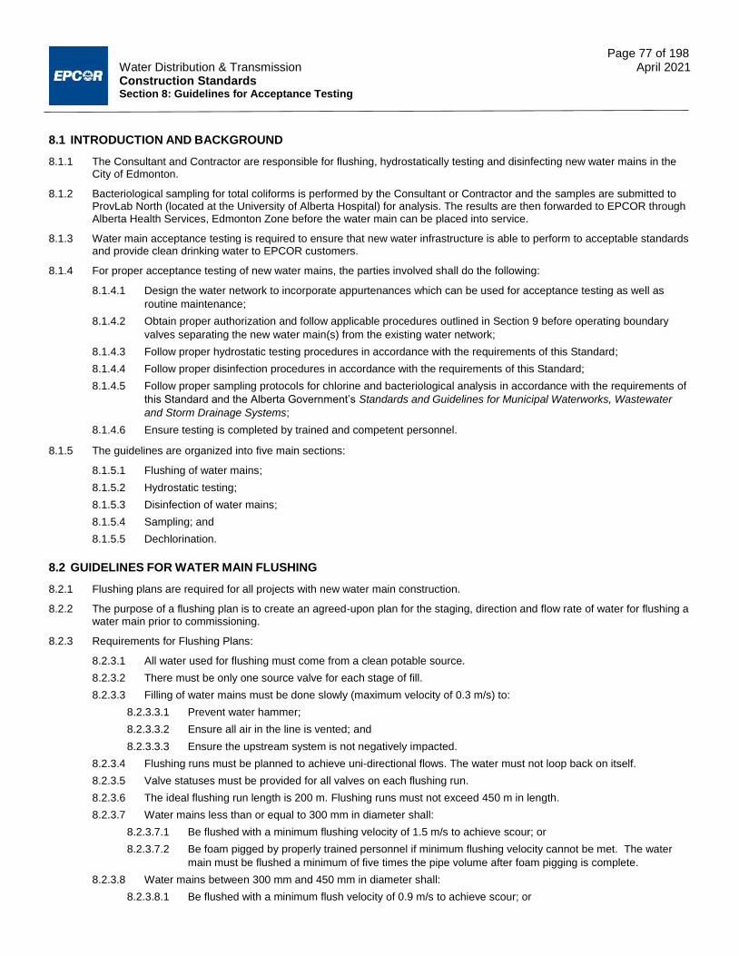
Page 77 of 198 Water Distribution & Transmission April 2021 Construction Standards Section 8: Guidelines for Acceptance Testing
8.1 INTRODUCTION AND BACKGROUND
8.1.1 The Consultant and Contractor are responsible for flushing, hydrostatically testing and disinfecting new water mains in the City of Edmonton.
8.1.2 Bacteriological sampling for total coliforms is performed by the Consultant or Contractor and the samples are submitted to ProvLab North (located at the University of Alberta Hospital) for analysis. The results are then forwarded to EPCOR through Alberta Health Services, Edmonton Zone before the water main can be placed into service.
8.1.3 Water main acceptance testing is required to ensure that new water infrastructure is able to perform to acceptable standards and provide clean drinking water to EPCOR customers.
8.1.4 For proper acceptance testing of new water mains, the parties involved shall do the following:
8.1.4.1 Design the water network to incorporate appurtenances which can be used for acceptance testing as well as
routine maintenance;
8.1.4.2 Obtain proper authorization and follow applicable procedures outlined in Section 9 before operating boundary
valves separating the new water main(s) from the existing water network;
8.1.4.3 Follow proper hydrostatic testing procedures in accordance with the requirements of this Standard;
8.1.4.4 Follow proper disinfection procedures in accordance with the requirements of this Standard;
8.1.4.5 Follow proper sampling protocols for chlorine and bacteriological analysis in accordance with the requirements of
this Standard and the Alberta Government’s Standards and Guidelines for Municipal Waterworks, Wastewater
and Storm Drainage Systems;
8.1.4.6 Ensure testing is completed by trained and competent personnel.
8.1.5 The guidelines are organized into five main sections:
8.1.5.1 Flushing of water mains;
8.1.5.2 Hydrostatic testing;
8.1.5.3 Disinfection of water mains;
8.1.5.4 Sampling; and
8.1.5.5 Dechlorination.
8.2 GUIDELINES FOR WATER MAIN FLUSHING
8.2.1 Flushing plans are required for all projects with new water main construction.
8.2.2 The purpose of a flushing plan is to create an agreed-upon plan for the staging, direction and flow rate of water for flushing a water main prior to commissioning.
8.2.3 Requirements for Flushing Plans:
8.2.3.1 All water used for flushing must come from a clean potable source.
8.2.3.2 There must be only one source valve for each stage of fill.
8.2.3.3 Filling of water mains must be done slowly (maximum velocity of 0.3 m/s) to:
8.2.3.3.1 Prevent water hammer;
8.2.3.3.2 Ensure all air in the line is vented; and
8.2.3.3.3 Ensure the upstream system is not negatively impacted.
8.2.3.4 Flushing runs must be planned to achieve uni-directional flows. The water must not loop back on itself.
8.2.3.5 Valve statuses must be provided for all valves on each flushing run.
8.2.3.6 The ideal flushing run length is 200 m. Flushing runs must not exceed 450 m in length.
8.2.3.7 Water mains less than or equal to 300 mm in diameter shall:
8.2.3.7.1 Be flushed with a minimum flushing velocity of 1.5 m/s to achieve scour; or
8.2.3.7.2 Be foam pigged by properly trained personnel if minimum flushing velocity cannot be met. The water
main must be flushed a minimum of five times the pipe volume after foam pigging is complete.
8.2.3.8 Water mains between 300 mm and 450 mm in diameter shall:
8.2.3.8.1 Be flushed with a minimum flush velocity of 0.9 m/s to achieve scour; or

Page 78 of 198 Water Distribution & Transmission April 2021 Construction Standards Section 8: Guidelines for Acceptance Testing
8.2.3.8.2 Be foam pigged by properly trained personnel if minimum flushing velocity cannot be met. The water
main must be flushed a minimum of five times the pipe volume after foam pigging is complete.
8.2.3.9 Water mains greater than or equal to 450 mm in diameter shall be foam pigged by properly trained personnel
then flushed with a minimum flush velocity of 0.9 m/s.
8.2.3.9.1 Water mains larger than 900 mm can be broom swept as an alternative to pigging. The sweepings must
be removed from the pipe before filling.
8.2.3.10 Water must be exchanged a minimum of five times to achieve a completed flush.
8.2.3.11 Water quality sampling reports must confirm a completed flush.
8.2.3.12 During a flush, the source water shall flow from larger pipe to smaller pipe, whenever possible.
8.2.3.13 Use Table 8.1 to find the number of ports required to achieve the requisite velocity. (Source AWWA C651-14).
Table 8.1: Number of ports required to achieve velocity for flushing
Pipe
Diameter
(mm)
Minimum
Velocity
Required (m/s)
Required flow (L/s)
for Minimum
Velocity
Number of
50 mm taps
Required
OR
No. of Hydrant Nozzles Required*
2.5" 4.5"
50 1.5 2.9 1 N/A N/A
100 1.5 11.8 1 N/A N/A
150 1.5 26.5 1 N/A N/A
200 1.5 47.1 2 1 N/A
250 1.5 73.6 2 2 1
300 1.5 106.0 N/A 2 1
350 0.9 86.6 N/A N/A 1
400 0.9 113.1 N/A N/A 1
450 0.9 143.1 N/A N/A 1
*With a 280kPa residual pressure a hydrant flowing to atmosphere will discharge 63 L/s from a 2.5" nozzle and 158 L/s from a
4.5" steamer (Source: After AWWA C651-14).
8.2.3.14 The discharge from the flushing pipe can be quickly estimated (±3 L/s) from the following equation and Figure 8.1:
𝑄 =5.5 × 10⁻⁵ ⋅ 𝑑2 ⋅ 𝑆𝑥
√𝑆𝑦
Where:
Q = discharge, L/s
d = discharge nozzle inside diameter, mm
Sx = the horizontal distance of discharge, mm
Sy = the vertical distance from the ground to the centre or nozzle, mm

Page 79 of 198 Water Distribution & Transmission April 2021 Construction Standards Section 8: Guidelines for Acceptance Testing
Figure 8.1: Estimating discharge from a hydrant or blowoff
8.3 GUIDELINES FOR HYDROSTATIC TESTING
8.3.1 PURPOSE
8.3.1.1 The purpose of hydrostatic testing a new water main is to determine if the installation is capable of withstanding
ordinary operating transient pressure conditions without failure or excessive leakage at the joints and service
connections.
8.3.1.2 The guidelines are intended to provide the performance criteria and testing protocol necessary for routine
hydrostatic testing to ensure that the new water main installation meets the design specifications.
8.3.2 BACKGROUND ON HYDROSTATIC TESTING
8.3.2.1 Hydrostatic testing consists of slowly charging a new section of water main to the distribution system pressure
from a boundary main. The valves are then closed on the test section. A tank of water and a purpose-specific
pump are used to pressurize the main to the specified test pressure.
8.3.2.1.1 The test is conducted for 2 hours during which time the pump is periodically operated to maintain the
pressure at the specified level.
8.3.2.1.2 The volume of water added to the water main from the tank is presumed to be equal to that which has
leaked from the water main during the test.
8.3.2.1.3 Figure 8.2 illustrates the conceptual layout of the apparatus required for hydrostatic testing.
8.3.2.2 Portland cement based materials such as concrete cylinder or cement-lined metallic pipes are porous and absorb
water during the initial charging of the water main.
8.3.2.2.1 A minimum of 24 hours of soaking is required to ensure that apparent water leakage is due to joints and
service leakage, not the absorption of water by the pipe material.

Page 80 of 198 Water Distribution & Transmission April 2021 Construction Standards Section 8: Guidelines for Acceptance Testing
Figure 8.2: Apparatus for Hydrostatic Testing
8.3.2.3 The working pressure is defined as the highest pressure experienced by the system during hydraulic modelling
between ADD, MDD, PHD, or special scenarios provided by EPCOR.
8.3.2.3.1 Design the working pressure at the low point and high point of the system as determined by the
hydraulic network analysis.
8.3.3 REQUIRED EQUIPMENT
8.3.3.1 The specifications for required equipment for hydrostatic testing are listed below. Equipment must be dedicated to
water main hydrostatic testing and must not be used for other construction activities.
8.3.3.1.1 ANSI Standard B40.1-1974 Grade A, or equivalent, Bourdon tube pressure gauge, range of 0 to 1400
kPa, with an accuracy of 1% of the full-scale reading, 7 kPa divisions, a minimum diameter of 90 mm,
and a scale which can be read in an arc of 270° (Walski, 1984).
8.3.3.1.1.1 The pressure gauge must be calibrated and certified annually and the certification must be submitted with all test results.
8.3.3.1.2 Hand or motor-powered pump capable of meeting required test pressures including necessary plumbing
accessories for preventing backflow and for enabling the flow rate to be controlled.
8.3.3.1.2.1 The pump should be provided with a pressure relief valve or should have an upper pressure limit of 1400 kPa.
8.3.3.1.3 Water storage tanks will be of non-corroding material.
8.3.3.1.3.1 The volume of the tank shall not be more than 10 times the allowable leakage for the duration of the test.
8.3.3.1.3.2 A depth gauge will be attached to the inside of the tank and will be calibrated for the volume of the tank.
8.4 PROCEDURE FOR HYDROSTATIC TESTING
8.4.1 GENERAL
8.4.1.1 The procedures for pressure and leakage testing are outlined in the following sections and are organized into two
parts:
8.4.1.2 General Procedures (independent of pipe material and size); and
8.4.1.3 Procedures that are influenced by the pipe material and size.

Page 81 of 198 Water Distribution & Transmission April 2021 Construction Standards Section 8: Guidelines for Acceptance Testing
8.4.2 GENERAL HYDROSTATIC TESTING PROCEDURES (INDEPENDENT OF PIPE MATERIAL AND SIZE)
8.4.2.1 Inform EPCOR inspectors of the date, time, and location of the hydrostatic test(s) at least 24 h prior to the test
time.
8.4.2.1.1 Failure to notify inspectors may result in the tests being rejected, requiring new tests to be
completed.
8.4.2.2 Inform all other construction crews or contractors that hydrostatic testing will be performed and ensure that no
valves are being operated during the test.
8.4.2.3 Identify the section of water main to be hydrostatically tested:
8.4.2.3.1 Maximum length of distribution water main test sections will be 450m unless otherwise directed by
EPCOR.
8.4.2.3.2 Maximum length of transmission water main test sections will be 800 m unless otherwise directed by
EPCOR.
8.4.2.3.3 Each section will be made up of only one type of pipe material.
8.4.2.3.3.1 If there are different types of pipe materials within the section of main, each pipe material must be tested separately prior to connection with other materials, with the exception of PVC to steel spool pieces for valve assemblies.
8.4.2.3.3.2 Fused PVC and jointed PVC are considered different materials for the purposes of hydrostatic testing.
8.4.2.4 Ensure the proper installation of all:
8.4.2.4.1 Water services;
8.4.2.4.2 Air relief services (temporary and permanent);
8.4.2.4.3 Flush points; and
8.4.2.4.4 Blowoffs.
8.4.2.5 Ensure that main stops are open and curb stops are closed.
8.4.2.6 Inspect all hydrants to ensure that they are properly installed and that all nipples are threaded or locked in place.
8.4.2.7 Open all hydrant control valves in the test section and close all hydrant boot valves.
8.4.2.8 Ensure thrust blocks and other restraining devices are in place and properly cured according to Section 13.
8.4.2.9 Confirm any boundary valves for the project are fully closed (see Section 9).
8.4.2.10 Open all main valves within the test section.
8.4.2.11 Place sufficient backfill to prevent pipe movement. Do not place permanent surfacing prior to the acceptance of
hydrostatic test results.
8.4.2.12 Fill and flush the water main according to Section 8.2.
8.4.2.13 Expel trapped air from the test section of water main by exhausting air at high points and dead-ends using
existing air relief valves or temporary main stops.
8.4.2.14 Close all air relief valves and temporary main stops prior to testing.
8.4.2.15 Raise the water-main pressure to the appropriate test pressure (see the section for the appropriate pipe material)
using either a hand or motor-powered pump located at a location approved by the EPCOR inspector. The hydrant
valve will be completely opened and the flow rate will be controlled by the valve at the pump.
8.4.2.16 Mark the gauge and the level of water in the storage barrel at the beginning of the test.
8.4.2.17 Maintain the test pressure within ± 20 kPa of the specified test pressure for the duration of the test.
8.4.2.18 Pump the test section back to the test pressure at the end of the first 30 min. If the allowable leakage is
exceeded, pressure test has failed. Correct cause(s) leading to test failure prior to starting new testing procedure.
8.4.2.19 At 30 min intervals during the test, walk along the test section and check for signs of leakage or distress at all
exposed appurtenances or fittings.
8.4.2.20 Calculate the allowable makeup water allowance based on the appropriate pipe material equations.
8.4.2.20.1 No allowance can be made for services, appurtenances or in-line valves.
8.4.2.21 Determine if the hydrostatic test passes or fails:
8.4.2.21.1 For all tests, provide written notification of the hydrostatic test result to the EPCOR Water Inspector
within 24 hours of completing the test.

Page 82 of 198 Water Distribution & Transmission April 2021 Construction Standards Section 8: Guidelines for Acceptance Testing
8.4.2.21.2 For all tests that fail:
8.4.2.21.2.1 Provide verbal notification to the EPCOR Water Inspector immediately after completion of the test; and
8.4.2.21.2.2 Provide written notification to the EPCOR Water Inspector within 24 hours of completing the hydrostatic test outlining the schedule for completing the required repairs.
8.4.3 SPECIFIC HYDROSTATIC TESTING PROCEDURES FOR POLYVINYL CHLORIDE
8.4.3.1 Refer to AWWA standard C605 and AWWA manual M23 for information on pressure and leakage testing.
8.4.3.2 Pressure capacity of PVC pipe involves of two types of pressure: internal hydrostatic pressure; and pressure
transients during operation.
8.4.3.3 Temperature greatly influences the ability of PVC pipe to contain hydrostatic pressure. The AWWA C900 and
C905 specifications are based on 23°C. Temperatures lower than this increase the hydrostatic pressure capacity.
Alternatively, temperatures greater than 23°C decrease the pressure capacity.
8.4.3.4 PVC differs from other materials in that it can resist momentary excessive pressures better than sustained long-
term excessive pressures.
8.4.3.5 Specific procedures for PVC pipe include all of the General Procedures (Section 8.4.1) plus the following:
8.4.3.5.1 Test pressure shall be determined as the highest of the following:
8.4.3.5.1.1 No less than 125% of the working pressure, as measured at the highest point in the test section.
8.4.3.5.1.2 No less than 150% of the working pressure measured at the lowest elevation of the test section.
8.4.3.5.1.3 1034 kPa (150 psi)
8.4.3.5.2 Test duration shall be a minimum of 2 hours.
8.4.3.5.3 Valves within the test section must not be operated for the duration for the pressure and leakage test.
8.4.3.5.4 The test pressure must not exceed the rated valve pressure (see AWWA C500) when resilient-seated
gate valves or butterfly valves are at the pressure boundary.
8.4.3.5.5 Makeup water allowance shall be calculated from the following formula:
𝑄𝑚 =𝐿𝐷√𝑃
795,000
Where: Qm = quantity of allowable makeup water, in liters per hour L = Length of pipe section being tested, in meters D = nominal diameter of the pipe, in millimeters P = average test pressure during the test in kilopascals
8.4.4 SPECIFIC HYDROSTATIC TESTING PROCEDURES FOR STEEL
8.4.4.1 Refer to AWWA C206 – Field Welding of Steel Water Pipe and AWWA Manual M11: Steel Pipe – A Guide For
Design and Installation for information on pressure and leakage testing of steel water pipe.
8.4.4.2 Specific procedures for steel pipe include all of the General Procedures (Section 8.4.1) as modified by the
following:
8.4.4.2.1 Per Section 8.3.2.2, fill cement mortar lined pipes with water 24 hours prior to hydrostatic
testing.
8.4.4.2.2 Steel water pipe shall be hydrostatically tested for a duration of not less than 4 hours.
8.4.4.2.3 Test pressure shall be determined as the highest of the following:
8.4.4.2.3.1 No less than 125% of the working pressure, as measured at the highest point in the test section.
8.4.4.2.3.2 No less than 150% of the working pressure measured at the lowest elevation of the test section.
8.4.4.2.3.3 1034 kPa (150 psi).
8.4.4.2.4 Valves within the test section must not be operated for the duration for the pressure and leakage test.
8.4.4.2.5 The test pressure must not exceed the rated valve pressure (see AWWA C500) when resilient-seated
gate valves or butterfly valves are at the pressure boundary.

Page 83 of 198 Water Distribution & Transmission April 2021 Construction Standards Section 8: Guidelines for Acceptance Testing
8.4.4.2.6 There is no allowed leakage for the testing of welded steel water mains.
8.4.4.3 In addition to the above standard hydrostatic testing procedure, the following testing methods from AWWA may
be permitted with approval from EPCOR:
8.4.4.3.1 Butt-welded joints and fillet welds can be tested with a vacuum box in accordance with Section 5.2.2.3 of
AWWA C206 – Field Welding of Steel Water Pipe.
8.4.4.3.2 Double-welded lap joints can be tested by shop-drilling and tapping a 6.4 mm national pipe thread hole
in the lap or bell end of the pipe and applying pressure to the annulus between the fillet welds.
Procedures shall be in accordance with AWWA C206 – Field Welding of Steel Water Pipe Section
5.2.2.2.
8.4.4.4 Use of air or other gaseous mediums for pressure testing of steel water mains is not permitted in any
circumstances.
8.4.5 HYDROSTATIC TESTING PROCEDURES FOR ALL OTHER PIPE MATERIALS
8.4.5.1 A dedicated engineered testing process according to relevant AWWA standards must be developed for all other
pipe materials, including but not limited to:
8.4.5.1.1 Ductile Iron Pipe;
8.4.5.1.2 High Density Polyethylene Pipe;
8.4.5.1.3 Reinforced Concrete Pressure Pipe (Steel Cylinder Type);
8.4.5.1.4 Reinforced Concrete Pressure Pipe (Non-cylinder Type);
8.4.5.1.5 Pre-stressed Concrete Pressure Pipe (Steel Cylinder Type); and
8.4.5.1.6 Concrete Pressure Pipe, Bar-Wrapped (Steel Cylinder Type).
8.4.6 SPECIFIC HYDROSTATIC TESTING PROCEDURES FOR FIRE HYDRANTS
8.4.6.1 Acceptance testing of hydrants consists of hydrostatically testing the hydrant at main pressure and
conducting a drainage test for dry-barrel hydrants. Consult the AWWA manual M17 for details on hydrant
installation, testing, and maintenance.
8.4.6.2 Hydrostatic Testing of Fire Hydrants at Main Pressure
8.4.6.2.1 Remove the highest nozzle cap and open the hydrant boot valve a few turns to allow the water to rise in
the barrel to the bottom of the nozzle.
8.4.6.2.2 Replace the nozzle cap securely, but leave it loose. Continue to charge the hydrant slowly, expelling the
air through the loose cap.
8.4.6.2.3 Tighten the nozzle cap when all of the air has been expelled.
8.4.6.2.4 Open the hydrant boot valve completely.
8.4.6.2.5 Check visually for leakage at the flanges, nozzles, operating stem, O-rings, and at any joints on the
hydrant body. Also use a listening device to detect any leaks below grade.
8.4.6.2.6 No leaks are permitted. Repair all faults and repeat the test.
8.4.6.3 Drainage Test for Dry-Barrel Hydrants
8.4.6.3.1 Following the pressure test, close the hydrant main valve.
8.4.6.3.2 Remove one nozzle cap and place the palm of one hand over the nozzle opening.
8.4.6.3.3 Drainage should be sufficiently rapid to create a noticeable suction.
8.4.6.3.4 If the hydrant fails the drainage test:
8.4.6.3.4.1 Partially open the hydrant with the nozzle caps on to create a pressure that will clear the drain valve.
8.4.6.3.4.2 If this fails, remove and inspect the drain valve assembly. If the drain valve is clear the drain outlet may be plugged from outside of the hydrant and will require digging down to clear the drain outlet
8.4.6.3.4.3 Repair all faults and repeat the test.

Page 84 of 198 Water Distribution & Transmission April 2021 Construction Standards Section 8: Guidelines for Acceptance Testing
8.5 GUIDELINES FOR DISINFECTION
8.5.1 PURPOSE
8.5.1.1 The purpose of disinfection is to destroy pathogenic microorganisms, which may occupy the water main after
construction is complete.
8.5.1.2 Chlorine is usually used as the disinfectant either as a compressed gas, calcium hypochlorite tablets/solution, or
as a sodium hypochlorite (bleach) solution.
8.5.1.3 A performance criterion for water main disinfection has been specified using the American Water Works
Association (AWWA) Standard C651. This standard comprehensively describes the minimum procedures to
be followed when preparing a water main for disinfection, disinfecting the water main, testing for chlorine
residual, and conducting bacteriological sampling. It refers to the latest edition of Standard Methods for the
Examination of Water and Wastewater for detailed methods for testing water quality and chlorine residual.
8.5.1.4 Disinfection consists of the following four tasks:
8.5.1.4.1 Preventing contamination of the new pipe during shipping, storage, and construction;
8.5.1.4.2 Flushing the water main to remove loose debris and dirt which may have entered the water-main
during construction. (Do not flush if hypochlorite tablets have been placed);
8.5.1.4.3 Chlorination of the water main to destroy pathogenic microorganisms; and
8.5.1.4.4 Bacteriological testing of the disinfected water to ensure that the microbiological water quality is
adequate.
8.5.2 WATER MAIN PREPARATION
8.5.2.1 Water main flushing is the most common form of preparation for disinfection except where hypochlorite
tablets have been used.
8.5.2.1.1 The flushing flow rate should be sufficient to achieve a minimum velocity of 0.91 m/s or 1.5 m/s,
depending on the water main diameter.
8.5.2.1.2 Section 8.2 outlines the procedure for flushing water mains.
8.5.3 CHLORINATION
8.5.3.1 The choice of chemical to use for chlorination is limited to sodium hypochlorite or calcium hypochlorite.
8.5.3.2 There are two accepted methods for chlorinating new water mains (AWWA C651):
8.5.3.2.1 Continuously fed sodium or calcium hypochlorite solution.
8.5.3.2.2 Calcium hypochlorite tablets placed during construction. This method of chlorination requires approval
by the Engineer prior to commencing construction.
8.5.3.3 Upon acceptance of the chlorine test results, the chlorinated water must be flushed from the main and
dechlorinated following the procedure outlined in Section 8.7.
8.5.3.4 The water main must not be depressurized after chlorination is complete.
8.5.3.5 Continuous-Feed:
8.5.3.5.1 The following procedure shall be followed if using the continuous feed chlorination method:
8.5.3.5.1.1 Notify the EPCOR Water Inspector in writing 72 hours prior to commencing activities.
8.5.3.5.1.2 Ensure all boundary valves are closed and stoppered.
8.5.3.5.1.3 Identify a main stop and service connection or bleeder as indicated on the engineering drawings within 3 m of the boundary valve for chemical feed.
8.5.3.5.1.3.1 DO NOT use fire hydrants for chemical feed. The high concentration chlorine solution
will damage the hydrant.
8.5.3.5.1.4 Under the supervision of the Inspector, open the discharge point and one boundary valve permitting water from the distribution system or other approved source to flow through the new water main at a constant, measured rate.
8.5.3.5.1.4.1 Use a pitot gauge or a container of known volume and stop watch to calculate the rate
of discharge.
8.5.3.5.1.4.2 Refer to Section 9 for guidance on operating boundary valves.
8.5.3.5.1.5 Slowly fill the water main, keeping the velocity below 0.3 m/s. Precautions shall be taken to ensure that air pockets are eliminated.

Page 85 of 198 Water Distribution & Transmission April 2021 Construction Standards Section 8: Guidelines for Acceptance Testing
8.5.3.5.1.6 Flush the water main according to methods described in Section 8.2 to remove particulates.
8.5.3.5.1.7 Inject the chlorine solution into the water main at a point no more than 3 m (10 ft.) downstream from the beginning of the water main.
8.5.3.5.1.8 Feed the chlorine solution at a constant rate such that the water entering the main to be disinfected will have no less than 25 mg/L of free chlorine and no more than 50 mg/L of free chlorine.
8.5.3.5.1.8.1 Free chlorine concentrations shall be measured at regular time intervals to ensure
appropriate concentration is achieved during filling.
8.5.3.5.1.8.2 Table 8.2 provides the amount of chlorine required for each 100 m of pipe for various
pipe diameters.
Table 8.2: Chlorine required to produce 25 mg/L concentration in 100 m of water main
Pipe diameter, mm 100% chlorine, g/100 m‡ 1% chlorine solution, L/100 m*‡
100 20 2.0
150 45 4.6
200 81 8.2
250 127 13
300 179 18
400 323 33
Source: (After AWWAC651-86)
*1.5 kg Ca(OCl)2 per 100 L ‡adjust for available chlorine of chemical used (see Appendix C for details)
8.5.3.5.1.9 Monitor the discharge location at regular intervals for chlorine residual using an approved field test kit. Discharge water must be dechlorinated. See Section 8.7 for dechlorination procedures.
8.5.3.5.1.10 Chlorine application shall not cease until the entire main is filled with chlorinated water with a chlorine residual of no less than 25 mg/L.
8.5.3.5.1.11 Operate all valves and hydrants within the test section to ensure they are disinfected.
8.5.3.5.1.12 Once 25 mg/L residual has been achieved, stop flow and chlorine feed. Chlorinated water shall remain in the water main for no less than 24 hours.
8.5.3.5.1.13 After 24 hours, test to confirm chlorine residual. 8.5.3.5.1.13.1 If residual is less than 10 mg/L, flush and re-chlorinate.
8.5.3.5.1.13.2 If the residual is more than 10 mg/L, the results are acceptable.
8.5.3.5.1.14 Notify EPCOR Water Inspector in writing with the chlorine residual results and time of test within 4 hours of completing the test.
8.5.3.5.1.15 Flush the heavily chlorinated water from the main, fittings, valves and branches until chlorine measurements meet normal system levels.
8.5.3.5.1.15.1 Flushed water must be dechlorinated. See Section 8.7 for dechlorination procedures.
8.5.3.6 Calcium Hypochlorite Tablets:
8.5.3.6.1 The following procedure shall be followed if using the calcium hypochlorite tablet method:
8.5.3.6.1.1 Notify the EPCOR Water Inspector in writing 72 hours prior to commencing activities.
8.5.3.6.1.2 Ensure all boundary valves are closed and stoppered.
8.5.3.6.1.3 DO NOT use the tablet method with solvent-welded plastic or screwed-joint steel since the
joint chemicals are incompatible with calcium hypochlorite.
8.5.3.6.1.4 Attach 5 gram calcium hypochlorite tablets to the inside and top of the water main using an adhesive that meets the requirements of NSF/ANSI 61.
8.5.3.6.1.5 Place at least one tablet in each of the following locations: 8.5.3.6.1.5.1 At the upstream end of each section of pipe to be disinfected, including branch lines;
8.5.3.6.1.5.2 At 150 m intervals along the section of pipe to be disinfected;
8.5.3.6.1.5.3 Within each hydrant lead; and
8.5.3.6.1.5.4 Within each appurtenance.

Page 86 of 198 Water Distribution & Transmission April 2021 Construction Standards Section 8: Guidelines for Acceptance Testing
8.5.3.6.1.6 The required number of 5 g tablets can be calculated from:
𝑁𝑜. 𝑜𝑓 𝑇𝑎𝑏𝑙𝑒𝑡𝑠 = 6.28𝑥10−6𝐷2𝐿
Where: No. of Tablets must be rounded up to nearest whole tablet; D = inside pipe diameter, mm L = length of pipe being disinfected, m
8.5.3.6.1.7 If the tablets are attached before the pipe section is placed in the trench, their positions shall be marked on the pipe exterior to indicate that the pipe has been installed with the tablets at the top.
8.5.3.6.1.8 DO NOT flush the water main once the tablets are in place.
8.5.3.6.1.9 Slowly fill the water main after construction is complete, keeping the velocity below 0.3 m/s, to prevent disturbing the tablets. Precautions shall be taken to ensure that air pockets are eliminated.
8.5.3.6.1.10 The chlorinated water shall remain in the pipe for at least 24 hours at water temperatures greater than 5°C; if the water temperature is less than 5°C the contact time shall be increased to 48 hours.
8.5.3.6.1.11 After 24 (or 48) hours, test to confirm chlorine residual. 8.5.3.6.1.11.1 If residual is less than 0.2 mg/L, flush and re-chlorinate.
8.5.3.6.1.11.2 If the residual is more than 0.2 mg/L, the results are acceptable.
8.6 GUIDELINES FOR SAMPLING
8.6.1 PURPOSE
8.6.1.1 The purpose of sampling a water main is to obtain information on the water quality in the pipe. The underlying
assumption which is important is that the sample is representative of the water in the water main. Good sampling
procedures are intended to provide the best opportunity for obtaining a representative sample.
8.6.2 GENERAL SAMPLING REQUIREMENTS
8.6.2.1 At least one sample of each type must be collected:
8.6.2.1.1 In 400 m intervals;
8.6.2.1.2 At the end of the water main; and
8.6.2.1.3 From each branch greater than one pipe length.
8.6.2.2 If trench water has entered the new main during construction or if, in the opinion of the Inspector, excessive
quantities of dirt or debris have entered the new main, samples shall be taken at intervals of 60 m.
8.6.3 CHLORINE SAMPLING REQUIREMENTS
8.6.3.1 Chlorine sampling must be completed by trained and competent personnel and performed with a certified chlorine
test kit appropriate for the chlorine levels.
8.6.3.1.1 High concentration chlorine residual shall be sampled at the beginning and end of the primary
disinfection period at all sampling locations.
8.6.3.1.2 Low concentration chlorine residual shall be sampled once the water main has been flushed of the
heavily chlorinated water at all sampling locations.
8.6.3.2 Chlorine test kits shall be calibrated every six months or per the manufacturer specifications, whichever is more
frequent.
8.6.4 BACTERIOLOGICAL SAMPLING REQUIREMENTS
8.6.4.1 Samples shall be collected no less than 16 hours and no more than 7 days after the chlorine test has passed;
8.6.4.2 One set of samples shall be collected and delivered to the lab:
8.6.4.2.1 At the start of the sampling period; and
8.6.4.2.2 16 hours after the first set of samples were collected.
8.6.4.3 Absolutely no flushing can occur before or between the two sets of samples.

Page 87 of 198 Water Distribution & Transmission April 2021 Construction Standards Section 8: Guidelines for Acceptance Testing
8.6.4.4 Sampling for bacteriological water quality parameters shall be done in such a way that prevents contamination
from bacteria in or on air, soil, water, clothing, or any parts of the human body. The following procedure will
ensure reliable results are obtained in the laboratory (Standard Methods for the Examination of Water and
Wastewater):
8.6.4.4.1 Obtain approved bacteriological sample bottles and the appropriate forms for potable water sampling
from the Provincial Laboratory of Public Health or the local Health Unit.
8.6.4.4.2 Keep the bottles closed until immediately prior to obtaining the sample. These bottles are sterilized and
contain a tablet of dechlorination reagent. NEVER rinse the sample bottles.
8.6.4.4.3 DO NOT sample from fire hydrants. Use a service connection or blowoff especially designed for
sampling the new water-main. Sample taps should be one-piece brass without aerators or other types of
screens.
8.6.4.4.4 DO NOT flush the water main prior to sampling.
8.6.4.4.4.1 The bacteriological test is meant to be a representative sample of water quality after the 16 hours hold time has elapsed.
8.6.4.4.4.2 Failure to adhere to this requirement will result in rejection of the sample results and requirement to re-start the testing process & timelines.
8.6.4.4.5 Prior to filling the sample bottle, complete the Provincial Laboratory of Public Health Form PH 108
(example shown in Appendix A).
8.6.4.4.6 Begin flowing water from the sample point at a very low flow rate.
8.6.4.4.7 Carefully break the seal on the sample bottle cap and unscrew. Take great care not to contaminate the
cap or the neck of the bottle with fingers or dirt.
8.6.4.4.8 Avoiding splashes, cut the water stream with the sample bottle and fill it until there is a head-space of
approximately 20 mm in the sample bottle (roughly to the shoulder of the sample bottle). Replace the
cap securely.
8.6.4.4.9 Shake the bottle 5 times to help the dechlorination reagent to dissolve.
8.6.4.4.10 Remove the sample identification number from the Provincial Laboratory of Public Health Form PH 108
and attach it to the sample bottle.
8.6.4.4.11 Bacteriological samples cannot be stored.
8.6.4.4.11.1 If the sample cannot be delivered to the Provincial Laboratory within 1 h of sampling, use an iced cooler for storage during transport.
8.6.4.4.11.2 In no case, should the samples be delivered to the Provincial Laboratory more than 6 h after the sample was collected.
8.6.4.4.11.3 NEVER leave sample bottles in the sunshine or expose them to elevated temperatures.
8.6.4.4.12 The bacteriological sampling results must be forwarded to the EPCOR Water inspector prior to the
onsite commissioning and construction completion inspection.
8.6.5 TASTE AND ODOUR SAMPLING REQUIREMENTS
8.6.5.1 Contact the EPCOR Water Inspector in writing a minimum of 72 hours prior to planned sampling to coordinate the
taste and odour sampling.
8.7 DECHLORINATION
8.7.1 GENERAL
8.7.1.1 The Developer and their Agents, Engineers and Contractors, are responsible for the water quality impacts of
water discharged during construction activities, including dechlorination of water disposed as part of acceptance
tests and disinfection.
8.7.1.2 Dechlorination must always be verified through field sampling of discharge waters.
8.7.1.3 Water discharged from the water distribution system and released to water bodies, either directly or indirectly
(e.g., via the storm-water sewer system), is to be dechlorinated at the point of discharge in accordance with the
applicable legislation.
8.7.1.3.1 This includes dechlorination of water released due to main breaks once the risks to public safety and
property damage have been controlled.

Page 88 of 198 Water Distribution & Transmission April 2021 Construction Standards Section 8: Guidelines for Acceptance Testing
8.7.1.3.2 For water disposed to the sanitary sewer system, there are limits on the chlorine concentration and
volume of water discharged as set by the City of Edmonton. Table 8.3 outlines the chlorine discharge
limits.
Table 8.3: Chlorine Discharge Limits
Discharge Location Total Cl2 Concentration Limit Source
Body of water (directly or via storm sewer)
0.5 μg/L The Canadian Water Quality Guidelines for the Protection of Aquatic Life (Canadian Council of Ministers of the Environment, 1999)
Sanitary or Combined Sewer 5.0 mg/L City of Edmonton Bylaw 18100 (2020)
The Canadian Water Quality Guidelines for the Protection of Aquatic Life (Canadian Council of Ministers of the Environment, 1999) sets a guideline residual chlorine concentration of 0.5 micrograms per litre (μg/L), which is below the reliable limits of detection (i.e., chlorine should be neutralized to the point where no chlorine is detected).
8.7.2 DECHLORINATION METHODS
8.7.2.1 Dechlorination may be performed by adding a neutralizing chemical to the chlorinated water as it is discharged.
8.7.2.2 Two common methods for applying the neutralizing chemicals are:
8.7.2.2.1 Continuous-feed, where neutralizing chemicals are applied at the point of water discharge; or
8.7.2.2.2 Dechlorination tank, where chlorinated water is discharged to a tank then treated to dechlorinate. The
tank may be mounted on a mobile trailer.
8.7.2.3 Depending on the method of dechlorination, the chemicals used may impact the dissolved oxygen concentration
of receiving waters, which may be a concern for the aquatic health of receiving wetlands and/or creeks1.
8.7.3 CHLORINE NEUTRALIZING CHEMICALS
8.7.3.1 The choice and amount of dechlorination chemical will be impacted by project or site specific issues such as
water release, temperatures, strength of chlorine, volume of water release and distance from receiving waters.
8.7.3.1.1 Table 8.4 below provides general information on various chlorine-neutralizing chemicals that can be
used as guidance in the field.
8.7.3.1.2 Refer to AWWA C655 for detailed information on standard industry practices for dechlorination.
8.7.3.1.3 Note that the chemical reaction time may be temperature-dependent.
8.7.3.2 Follow all manufacturer’s recommendations and safe work procedures when handling dechlorination chemicals.
8.7.3.3 Adhere to all applicable safety regulations including: Workplace Hazardous Materials Information System
(WHMIS), Occupational Health and Safety (OH&S) and Transportation of Dangerous Goods (TDG).
1 The Canadian Water Quality Guidelines for the Protection of Aquatic Life (Canadian Council of Ministers of the Environment, 1999)
set a lowest acceptable concentration of dissolved oxygen in cold water of 9.5 milligrams per litre (mg/L) to protect aquatic life in their early life stages.

Page 89 of 198 Water Distribution & Transmission April 2021 Construction Standards Section 8: Guidelines for Acceptance Testing
Table 8.4: Summary of Dechlorination Chemicals
Name of Chlorine-
neutralizing chemical
Chemical formula
Approximate parts of chemical required to neutralize 1 part of
chlorine
Comments*
Sulfur dioxide
SO2 1.1
Reducing agent; may deplete dissolved oxygen in the water. Can reduce the pH of the water significantly. Extremely irritating gas. Best suited for use in treatment plants and pumping stations, not field use.
Sodium bisulfite
NaHSO3 1.5 Reducing agent; depletes dissolved oxygen in the water. Available as a white powder, granule or clear liquid solution. Highly corrosive, and a skin, eye and respiratory tract irritant.
Sodium sulfite
Na2SO3 1.8
Reducing agent; may deplete dissolved oxygen in the water. Available in powder/crystalline and tablet form. Dechlorination tablets are effective for constant, low flow rate chlorinated
releases. Currently used by EPCOR (LPD-CHLOR tablets). Suitable for chlorine concentrations of less than 4 mg/L.
Sodium thiosulfate
Na2S203 2.0
Varies with pH
Reducing agent; may deplete dissolved oxygen in the water. Skin, eye, nose and throat irritant. Low toxicity to aquatic species (USEPA toxicity study) May react slowly and requires more time for dechlorination. Over-dechlorination can encourage bacterial growth in the receiving
streams.
Ascorbic acid
C608H6 2.5
No known impact on dissolved oxygen. May decrease pH of water. Available in tablet form. Skin, eye and lung irritant. Store in a dry state and prepare solution at the time of use.
Sodium Meta-
bisulfite Na2S205 1.4
Reducing agent; depletes dissolved oxygen in the water. Available as crystal, powder or solution form. Eye, throat, skin and lung irritant. Used by EPCOR to neutralize super-chlorinated water during the
commissioning of a 1500 mm transmission main at EL Smith.
Calcium thiosulfate
CaS203 Varies with pH
No known impact on pH or dissolved oxygen. Not toxic to aquatic species. Over-dechlorination can cause high turbidity and encourage bacterial
growth in the receiving streams. Dechlorination reactions require nearly 5 minutes for complete
neutralization. Currently used by EPCOR for high chlorine concentrations (CAPTOR, 20
to 300 mg/L)
*Information sources: Tikkanen et al., Guidance Manual for Disposal of Chlorinated Water and AWWA C655
8.7.4 FIELD SAMPLING
8.7.4.1 Verify that the water discharge stream is sufficiently dechlorinated to meet applicable legislation and bylaws via
field sampling of residual chlorine concentration.

Page 90 of 198 Water Distribution & Transmission April 2021 Construction Standards Section 8: Guidelines for Acceptance Testing
8.8 ACCEPTANCE TESTING RELATED LITERATURE
8.8.1 AWWA, C651. Disinfecting for Water Mains. American Water Works Association, Denver, CO.
8.8.2 AWWA, Concrete pressure pipe. Manual M9, American Water Works Association, Denver, CO.
8.8.3 AWWA, Installation, operation, and maintenance of fire hydrants. Manual M17, American Water Works Association, Denver, CO.
8.8.4 AWWA, 1999. Maintaining distribution-system water quality. American Water Works Association, Denver, CO.
8.8.5 AWWA, PVC pipe - design and installation. Manual M23, American Water Works Association, Denver, CO.
8.8.6 Burman, N.P., 1987. Distribution systems. Journal of Environmental Pathology, Toxicology, and Oncology, 7(5/6): 279-302.
8.8.7 City of Edmonton Private Development Inspection and Testing Procedure. ISO-9001-94 (1997)
8.8.8 Gordon, G., Cooper, W.J., Rice, R.G., and Pacey, G.E. 1988. Methods of measuring disinfectant residuals. Journal of the American Water Works Association 80(9):94-108.
8.8.9 Greenberg, A.E., L.S. Clesceri, and A.D. Eaton editors. 1992. Standard Methods for the Examination of Water and Wastewater. 18th edition. Washington, DC: American Public Health Association, American Water Works Association, Water Environment Federation.
8.8.10 Health and Welfare Canada. Sixth Edition 1996. Guidelines for Canadian drinking water. Ottawa, Ontario.
8.8.11 Uni-Bell, Handbook of PVC pipe, design and construction, Uni-Bell Plastic Pipe Association, Dallas, TX.
8.8.12 Walski, T.M., 1984. Analysis of water distribution systems. Van Nostrand Reinhold Company, New York, NY.
END OF SECTION

Construction Standards
Section 9 Guidelines for Boundary Valve
Operation
April 2021

Page 92 of 198 Water Distribution & Transmission April 2021 Construction Standards Section 9: Guidelines for Boundary Valve Operation
9.1 PURPOSE
9.1.1 Boundary valves are valves which isolate new water-main construction from existing water-mains serving people with potable water. These valves protect the public from accidental contamination of their drinking water caused by backflow from contaminated water-mains or mains which have excessive residual chlorine concentrations. In addition, boundary valves prevent excessive hydrostatic pressure being applied to domestic water services during pressure testing of new water-mains. Care must be taken when opening and closing boundary valves to ensure that the water serving houses remains safe for consumption and that the customer is not inconvenienced.
9.1.2 Boundary valves may be on existing City property or in the new development. In some cases, the boundary valve may be one or more valves away from the development. Regardless of the boundary valve location, boundary valves should not be turned unless the operator fully understands the location and function of the valves.
9.2 OPERATING RULES
9.2.1 Water-main design drawings must have all boundary valves clearly marked prior to construction.
9.2.2 The Consultant is responsible for the operation of boundary valves in both new developments and renewal projects.
9.2.3 Prior to construction, the Consultant will designate a trained and competent site representative who will be responsible for ensuring that operation of boundary valves, pressure and leakage testing, and disinfection are properly performed.
9.2.4 Boundary valves will be closed and stoppered before construction starts as per the approved engineering drawings.
9.2.4.1 EPCOR Water Inspector must be onsite for the closing and stoppering of the valves.
9.2.4.2 Hazardous energy isolation devices must be installed in accordance with Alberta Occupational Health and
Safety Code Part 15 Managing the Control of Hazardous Energy .
9.2.5 Have only one boundary valve open at one time to prevent backflows.
9.2.6 Valves 300 mm in diameter and smaller must be operated under the supervision of an EPCOR Water Inspector.
9.2.6.1 The EPCOR Water Inspector must be contacted a minimum of 48 hours in advance.
9.2.6.2 Additional notice may be required on a case by case basis.
9.2.7 Valves 350 mm in diameter and larger must be operated by EPCOR Water Operations Staff.
9.2.7.1 The EPCOR Water Inspector must be contacted a minimum of 72 hours in advance to make arrangement for
the operation of these valves.
9.2.7.2 Additional notice may be required on a case by case basis.
9.2.8 Boundary valves must remain closed and stoppered until new water mains are accepted, except for the following construction activities:
9.2.8.1 Filling water mains for wet-tapping of services;
9.2.8.2 Hydrostatic testing; and
9.2.8.3 Disinfection and subsequent flushing.
Notice must be provided to the EPCOR Water Inspector prior to the commencement of these activities. Boundary valve management in accordance with Section 9.2.6 and 9.2.7 must be completed.
9.2.9 The Consultant is responsible for obtaining approval from the EPCOR Water Inspector to operate and change the status of any boundary valves. The Inspector must be onsite to witness any operation or changes in status.
END OF SECTION

Construction Standards
Section 10 PVC Tapping Guidelines
April 2021

Page 94 of 198
Water Distribution & Transmission April 2021 Construction Standards Section 10: PVC Tapping Guidelines
10.1 GENERAL
10.1.1 This section covers the guidelines for the tapping of PVC potable water pipe manufactured to AWWA Standards C900 and C905.
10.1.2 EPCOR presently uses C900 and C905 pipe in 150 mm to 300 mm and 350 mm to 1200 mm nominal diameters respectively.
10.1.3 The intent of these guidelines is not to provide detailed field instructions but to highlight critical aspects of tapping and to clarify EPCOR’s position on tapping equipment and procedures.
10.1.3.1 The manufacturer’s recommended installation procedure is to be obtained for all materials installed.
10.1.3.2 In the case of discrepancy between the manufacturer’s requirements and these specifications, advise EPCOR
and request instruction before proceeding.
10.1.4 The critical aspects of tapping equipment and procedures which are covered in the guidelines, and to which specific attention should be paid, are:
10.1.4.1 Using the proper shell cutter, in good condition;
10.1.4.2 Using a drilling machine with a feed nut independent of the boring bar;
10.1.4.3 Monitoring the depth of the cut;
10.1.4.4 Observing minimum 600 mm from pipe ends, minimum 600 mm separation and 30 degree stagger;
10.1.4.5 Avoid distorting the pipe when mounting the tapping machine;
10.1.4.6 Cutting and tapping at a slow and steady feed rate;
10.1.4.7 Always retrieving the coupon;
10.1.4.8 Checking for leaks;
10.1.4.9 Tapping of curved pipe under pressure may increase the possibility of failure during tapping;
10.1.4.9.1 Whenever practicable, taps should be made on the inside radius of longitudinally bent pipe; and
10.1.4.10 OH&S due diligence regarding the specific hazards of this task.
10.2 RESOURCES
10.2.1 Unless otherwise designated, all specifications and standard references refer to the latest edition.
10.2.1.1 AWWA C605 – Underground Installation of Polyvinyl Chloride (PVC) Pressure Pipe and Fittings for Water
10.2.1.2 AWWA M23 – PVC Pipe—Design and Installation
10.2.1.3 Uni-Bell Handbook of PVC Pipe Design and Construction
10.2.1.4 Uni-Bell UNI-PUB-08-16 – PVC Pressure Pipe Tapping Guideline
10.2.1.5 Manufacturer/Supplier Manual/Installation Guide for the specific tapping equipment used
10.2.2 The training video, "Tapping PVC Pressure Pipe" by the Uni-Bell PVC Pipe Association is mandatory for all personnel directly involved in the tapping of PVC pipe.
10.2.3 For further details on equipment and procedures, please contact the specific suppliers of the pipe materials and the tapping equipment that are in use on the job site.
10.3 CONSIDERATIONS
10.3.1 RISK OF TRENCH FLOODING
10.3.1.1 The Contractor should be aware of the specific hazards pertaining to working around pressurized water mains.
There is a risk of rapid ingress of a large volume of water into an excavation in the event of a failure.
10.3.1.2 Ladders extending above the trench wall should be easily accessible by all personnel.
10.3.1.3 It is recommended that all of the water main isolating valves on either side of the proposed tap be closed, except
for one which may be left minimally opened, so that the effect of any failure will be mitigated.
10.3.1.4 Prior to the tap, the water main isolating valves must be located and contingency plans made for their immediate
shut off should a failure occur.
10.3.1.5 Follow notification requirements outlined in Section 2.3.8.
10.3.1.6 Contact the EPCOR Water Inspector a minimum of 48 hours in advance of valve operations.
10.3.1.6.1 Refer to Section 9 for guidance on operating boundary valves.

Page 95 of 198
Water Distribution & Transmission April 2021 Construction Standards Section 10: PVC Tapping Guidelines
10.3.1.7 A protective blanket with a hole in the center to permit installation of the tapping machine should be used to cover
the exposed area of the pipe.
10.3.2 TAPPING CATEGORIES
10.3.2.1 Table 10.1 based on the existing field parameters such as the pipe type, pipe size, tap type and tap size.
Table 10.1: Pipe tapping categories
Category Pipe Type Pipe Size (mm)
Tap Diameter (mm)
Tap Type Type Allowable
1 AWWA C900 100 to 300 20,25 direct wet
2 AWWA C900 100 to 300 40,50 saddle wet
3 AWWA C900 100 to 300 150 to 300 sleeve wet
4 AWWA C905 350 to 600 20,25,40,50 saddle dry or isolated wet
5 AWWA C905 350 to 1200 150 to 750 sleeve wet
10.3.2.2 Equipment specifications and procedures for each category are generally described in Table 10.2, Table 10.3,
and Table 10.4.
10.3.2.3 Direct and saddle dry tapping will be allowed only on a site specific basis, with the prior review and documented
approval of the EPCOR Water representative.
10.3.2.3.1 The Contractor must demonstrate that dry tapping is the best practice for the specific conditions.
10.3.2.3.2 Examples of conditions that may support dry tapping include sub-zero ambient temperature and limited
working space in shored excavations.
10.3.2.4 The Contractor must ensure that the tapping machines, drill bits, shell cutters and associated equipment are
properly maintained and in sound working condition, for safe operation.
10.3.2.5 The Contractor must ensure that personnel are properly trained and are competent to operate the equipment and
perform the task completely and safely.
10.3.2.6 For more information, please reference the Uni-Bell PVC Pipe Association’s PVC Pressure Pipe Tapping
Guideline, available from the Uni-Bell website.

Page 96 of 198
Water Distribution & Transmission April 2021 Construction Standards Section 10: PVC Tapping Guidelines
Table 10.2: Pipe tapping equipment and procedures for Category 1
EQUIPMENT PROCEDURE Pipe - AWWA C900 PVC, DR 18, DR 14 - C.I.O.D.
- Allowable temperature bands: -18oC to 38oC (dry tap) 0oC to 32oC (wet tap)
I. Planning
- Do not tap closer than 600 mm from the end of the pipe.
- Stagger multiple taps at least 600 mm apart with adjacent taps and offset 30o with respect to each other
- Do not tap a discolored surface. - Do not tap a curved pipe where bend radius
is less than 300 times the pipe O.D. - Check the cutter condition. It should be in
good condition and be kept sharp. - Determine tapping depth. Perform "bench"
test and note position of top of threaded feed sleeve relative to thrust collar or other datum point
IV. Inserting Main Stop
- Attach an E-Z screw plug to the end of the boring bar.
- Screw mainstop into E-Z release plug.
- Ensure main stop is closed. - Apply 2 spiral wraps of "Teflon" tape
clockwise to the inlet threads of the mainstop. Do not use liquid sealants.
- Replace boring bar in machine and proceed to insert mainstop into pipe. Exercise care and do not force or punch first few threads.
- Remove ratchet handle as soon as stop has firmly engaged the threads in the pipe wall.
- Use a torque wrench and tighten to 27 foot-pounds (36.6 newton- metres).
- Turn the wrench counter clockwise to release E-Z plug from stop. Remove machine.
- At correct insertion, 1 to 3 threads should be visible.
- If leaking occurs, tighten to 35 foot- pounds (47.5 newton-metres).
- If leaking persists, remove pressure from line, unscrew mainstop to clear away cuttings and replace stop with new Teflon tape to 27 foot-pounds (36.6 newton-metres).
Main Stop
- AWWA C800 (tapered) inlet thread
Saddle or Sleeve
- not required
Tapping Machine
- Standard ratchet handle on boring bar - Feed nut or feed screw and yoke
- Machine saddle must be compatible with pipe O.D.
- Acceptable machines are:
1. Footage Tool/Mainline Tap
2. Mueller/B-100, B, A2, A3
3. Romac/Transmate B-1
II. Machine Mounting
- Sit machine firmly on drilling site. The pipe should not be distorted as a result of mounting machine
- Adjust nuts on chain hooks so nuts are even with tops of threads. Position chain hooks on machine and loop chain links snugly. This process should ensure that machine remains correctly seated in the saddle and saddle gasket.
- Tighten nuts alternately so the same number of threads show when the machine is correctly mounted. Over-tightening on one side may distort the pipe wall. Tighten only enough to hold machine in place - no more.
- Do not use wrench extenders.
Shell Cutter or Tapping Tool
- Must be classified as a core cutting tool - Double or multiple slot design - Must retain coupon - Must have sufficient throat depth to
accommodate DR14 pipe wall - Shank of cutter must be adaptable
to the tapping machine - Acceptable cutters/tapping tools are: 1. Utility Services/4 point
2. Anderson Metals Combination Cutter and Tap
3. Romac/Transmate 353-04- 206/351-01-206, 353-04- 208/351-01-208
III. Cutting and Tapping
- Rotate ratchet handle 1 complete turn for every 1/8 turn of feed yoke. A slow feed rate will help to ensure a good tap.
- The use of a cutting lubricant is recommended. If an increase in boring bar resistance is encountered, remove the boring bar, clean shavings out of the cutter, re-lubricate and resume cutting
- On wall penetration use feed yoke to engage first few turns of tapping tool in the hole. Feed yoke can be disengaged at this point.
- The feed rate should be less in cold weather. Judge correct feed rate by "finger pull".
- Tap remainder of hole and re-engage feed yoke when reversing tapping tool until tap clears threads.
- Examine PVC coupon for abnormalities
V. Dry Tapping
- Follow the procedures as outlined above with the following exceptions:
1. Remove cuttings from hole before inserting mainstop.
2. Insert the mainstop by hand.
3. Do not cross-thread Teflon- wrapped threads.

Page 97 of 198
Water Distribution & Transmission April 2021 Construction Standards Section 10: PVC Tapping Guidelines
Table 10.3: Pipe tapping equipment and procedures for Categories 2 and 4
EQUIPMENT PROCEDURE Pipe
- AWWA C900, DR18, DR14 - AWWA C905 PVC, DR25 - C.I.O.D. - Allowable temperature bands:
-18oC to 38oC (dry tap) 0oC to 32oC (wet tap)
Tapping Machine
- Standard ratchet handle on boring bar - Feed nut or feed screw and yoke - Machine saddle must be compatible with
pipe O.D. - Acceptable machines are:
1. APAC/Drillmaster 901
2. Footage Tool/Main line tap, Mini tap
3. Ford/77
4. Mueller/D5, E5
5. Romac/Transmate 5930, 5935
I. Planning
- The following procedures are for dry and wet tapping.
- Prior approval from EPCOR is required for dry tapping.
- Do not tap closer than 600 mm from the end of the pipe.
- Stagger multiple taps at least 600 mm apart with adjacent taps and offset 30o with respect to each other
- Do not tap a discolored surface. - Do not tap a curved pipe where
bend radius is less than 300 times the pipe O.D.
- Check the cutter condition. It should be in good condition and be kept sharp.
Main Stop
- AWWA C800 (tapered) inlet thread
Saddle
- Provide full support around pipe circumference
- Have total minimum band width of 50 mm (2 inches)
- Should not have lugs that dig into pipe when saddle is tightened
- Should not have U-bolt type of strap
Shell Cutter
- Must be classified as a core cutting tool - Double or multiple slot design - Must retain coupon - Must have sufficient throat depth to
accommodate DR14 pipe wall - Shank of cutter must be adaptable to the
tapping machine - Acceptable cutters/tapping tools are:
1. Footage Tools/T500-2, T700-2, T408- 11, T409-11
2. Ford/DMSC3, DMSC4, DMHS-6, DMHS-7
3. Pipeline Products PWL 3/4, 1, 1 3/4, 2 4.
Romac/Transmate 351-01-206, 350-01-
208, 351-01-212, 35-01-216
5. Utility Services/4 point
II. Machine Mounting
- Evenly tighten saddle to pipe. Install as per manufacturer's instructions and do not over-tighten.
- Apply thread sealant and screw inlet side of main stop into the saddle. Retain stop hardware.
- Do not use liquid sealants. - Use an appropriate adapter and gasket. - Attach drilling machine to main stop
outlet threads. Ensure main stop is open.
III. Cutting and Tapping
- Rotate ratchet handle 1 complete turn for every 1/8 turn of feed yoke. A slow feed rate will help to ensure a good tap.
- The feed rate should be less in cold weather. Judge correct feed rate by "finger pull".
- The use of a cutting lubricant is recommended.
- Withdraw cutter and close main stop.
- Remove drilling machine.
- Examine PVC coupon for abnormalities.
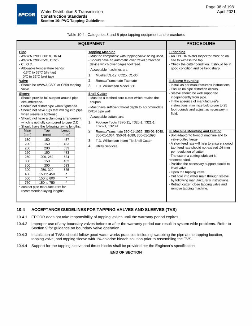
Page 98 of 198
Water Distribution & Transmission April 2021 Construction Standards Section 10: PVC Tapping Guidelines
Table 10.4: Categories 3 and 5 pipe tapping equipment and procedures
EQUIPMENT PROCEDURE
Pipe
- AWWA C900, DR18, DR14
- AWWA C905 PVC, DR25
- C.I.O.D.
- Allowable temperature bands:
-18oC to 38oC (dry tap)
0oC to 32oC (wet tap)
Tapping Machine
- Must be compatible with tapping valve being used.
- Should have an automatic over travel protection
device which disengages tool feed.
- Acceptable machines are:
1. Mueller/CL-12, CC25, C1-36
2. Romac/Transmate Tapmate
3. T.D. Williamson Model 660
I. Planning
- An EPCOR Water Inspector must be on
site to witness the tap.
- Check the cutter condition. It should be in
good condition and be kept sharp.
Valve
- Should be AWWA C500 or C509 tapping
valve
II. Sleeve Mounting
- Install as per manufacturer's instructions.
- Ensure no pipe distortion occurs.
- Sleeve should be well supported
independently from pipe.
- In the absence of manufacturer's
instructions, minimize bolt torque to 25
foot-pounds and adjust as necessary in
field.
Sleeve
- Should provide full support around pipe
circumference.
- Should not distort pipe when tightened.
- Should not have lugs that will dig into pipe
when sleeve is tightened.
- Should not have a clamping arrangement
which is not fully contoured to pipe O.D.
- Should have the following laying lengths:
Main
(mm)
Tap
(mm)
Length
(mm)
150 150 457
200 150 483
200 200 533
250 150 483
250 200, 250 584
300 150 483
300 200 533
300 250, 300 635
450 150 to 450 *
600 150 to 600 *
750 150 to 750 *
* contact pipe manufacturers for
recommended laying lengths
Shell Cutter
- Must be a toothed core cutter which retains the
coupon.
- Must have sufficient throat depth to accommodate
DR14 pipe wall
- Acceptable cutters are:
1. Footage Tools T376-11, T320-1, T321-1, T322-1, T323-1
2. Romac/Transmate 350-01-1032, 350-01-1048, 350-01-1064, 350-01-1080, 350-01-1096
3. T.D. Williamson Insert Tip Shell Cutter
4. Utility Services
III. Machine Mounting and Cutting
- Bolt adaptor to front of machine and to
valve outlet flange.
- A slow feed rate will help to ensure a good
tap, feed rate should not exceed .08 mm
per revolution of cutter
- The use of a cutting lubricant is
recommended.
- Position the necessary support blocks to
level valve.
- Open the tapping valve.
- Cut hole into water main through sleeve
by following manufacturer's instructions.
- Retract cutter, close tapping valve and
remove tapping machine.
10.4 ACCEPTANCE GUIDELINES FOR TAPPING VALVES AND SLEEVES (TVS)
10.4.1 EPCOR does not take responsibility of tapping valves until the warranty period expires.
10.4.2 Improper use of any boundary valves before or after the warranty period can result in system wide problems. Refer to Section 9 for guidance on boundary valve operation.
10.4.3 Installation of TVS's should follow good water works practices including swabbing the pipe at the tapping location, tapping valve, and tapping sleeve with 1% chlorine bleach solution prior to assembling the TVS.
10.4.4 Support for the tapping sleeve and thrust blocks shall be provided per the Engineer's specification.
END OF SECTION

Construction Standards
Section 11 Product Approval Procedures
April 2021

Page 100 of 198 Water Distribution & Transmission April 2021 Construction Standards Section 11: Product Approval Procedures
11.1 GENERAL
11.1.1 SCOPE
11.1.1.1 This section covers the procedures for the approval of products to be used in Edmonton’s potable water
distribution system. The information has been broken down into the following segments:
11.1.1.1.1 Product Approval Procedures, which shall act as guidelines for processing applications from
manufacturers or distributors who wish to have their product approved;
11.1.1.1.2 Product Evaluation Form, which is to be completed by the manufacturer or distributor prior to their
application; and
11.1.1.1.3 Approved Products List, which is updated by EPCOR to show the products approved for use in the City
of Edmonton.
11.2 PRODUCT APPROVAL PROCEDURES
11.2.1 APPLICATION
11.2.1.1 The manufacturer or distributor is to submit a Product Evaluation Form available from EPCOR’s website along
with a covering application letter to the Manager of Engineering and Development, Distribution Technical
Services, EPCOR Water Services.
11.2.1.1.1 Email applications to [email protected]
11.2.1.2 The applicant shall:
11.2.1.2.1 Provide permanent representation in the province of Alberta for the product under consideration;
11.2.1.2.2 Co-operate in the submission of product documentation necessary to evaluate the product;
11.2.1.2.3 Assume all incidental costs (such as testing by a third party) to demonstrate compliance with EPCOR
Water specifications; and
11.2.1.2.4 Attach all drawings, photographs, catalogues, warranties, notarized affidavits of compliance, etc.
11.2.2 REVIEW
11.2.2.1 EPCOR will review the suitability of the product by:
11.2.2.1.1 Soliciting comments from sections within the corporation.
11.2.2.1.2 Reviewing all promotional details provided by the manufacturer/distributor.
11.2.2.1.3 Soliciting comments from agencies outside of the corporation such as:
11.2.2.1.3.1 The City of Edmonton Construction Branch
11.2.2.1.3.2 The City of Edmonton Materials Engineering
11.2.2.1.3.3 Testing Agencies
11.2.2.1.3.4 Private Contractors
11.2.2.1.3.5 Other Municipalities
11.2.2.1.4 Meeting with suppliers as necessary.
11.2.2.1.5 Conducting field trials or pilot installations.
11.2.3 APPROVAL/REJECTION
11.2.3.1 Approval can be granted to a product on a temporary, conditional, or trial basis based on the results of the review.
11.2.3.2 All approvals will be communicated via written notification to the requesting manufacturer or distributor.
11.2.3.2.1 Copies of this notification will also be forwarded to the EPCOR Supply Chain Management, the City of
Edmonton and other interested parties when required.
11.2.3.3 EPCOR reserves the right to reject any product submitted for approval based on inadequate results or suitability
discovered during the review process.
11.2.3.3.1 Rejection of a product along with a full explanation will be communicated to the requesting manufacturer
or distributor via written notification.
11.2.3.4 Temporary, conditional or trial approval will be issued in writing with a start and end date.
11.2.3.4.1 Prior to the end date documented trial results and field experience will be gathered and reviewed.
11.2.3.4.2 At the end date following the review, a permanent approval, a rejection, or a further temporary,
conditional or trial approval may be issued.

Page 101 of 198 Water Distribution & Transmission April 2021 Construction Standards Section 11: Product Approval Procedures
11.2.4 APPEALS
11.2.4.1 All requesting manufacturers or distributors have the right to appeal the rejection of their product.
11.2.4.2 An appeal can be made by forwarding supporting evidence along with a cover letter that rebuts the statements
made in the letter of rejection.
11.2.4.2.1 Upon receiving this letter, EPCOR will review the product again, and issue a written decision.
11.2.4.3 If a product is accepted upon appeal, a temporary or conditional approval will be issued for a 1-year time frame.
11.2.4.3.1 After this period, a review will occur at which time a permanent approval may be issued.
11.2.4.4 If a product is rejected upon appeal, the manufacturer or distributor cannot re-submit the same product for
approval unless a three year time period has passed and there has been significant upgrades to the product that
warrant a new review, by EPCOR’s judgement.
11.2.5 REQUIRED NOTIFICATION
11.2.5.1 EPCOR Water Services must be notified by the manufacturer or distributor of any change to an approved
product. This includes, but is not limited to, a change in the following:
11.2.5.1.1 Material, available diameter or performance rating;
11.2.5.1.2 Manufacturing process;
11.2.5.1.3 Design or configuration;
11.2.5.1.4 Part number; or
11.2.5.1.5 Availability.
11.2.5.2 Significant changes may result in the need for a new evaluation, review and approval.
11.2.6 REMOVAL OF A PRODUCT FROM THE APPROVED MATERIALS LIST
11.2.6.1 EPCOR Water services reserves the right to remove any product from the approved materials list that
11.2.6.1.1 No longer meets the current standards;
11.2.6.1.2 Has, after initial approval, undergone a change to design or configuration that renders the product
incompatible with other EWSI approved products;
11.2.6.1.3 Has received numerous documented complaints from contractors or staff;
11.2.6.1.4 Is found to be below the standard of similar products that are readily available; or
11.2.6.1.5 Is no longer reasonably available.
11.2.6.2 The applicable supplier will be contacted in writing prior to product removal in order to provide them with the
opportunity to respond to complaints, comments or issues.
11.2.6.3 The applicable supplier will be provided with documentation supporting the decision to remove the product from
the list.
11.3 APPROVED PRODUCT LIST
11.3.1 WATER SERVICES
Table 11.1: Main Stops - Select connections to suit Service Tubing material
Manufacturer Model/Type Size (mm) Remarks
Cambridge Brass 301Series 20 to 50 AWWA C800
Compression or Kitec ends
Ford FB, QJ and QJNK
Series 20 to 50
AWWA C800 Compression or Kitec ends
Mueller B2500 Series 20 to 50 AWWA C800
Compression or Kitec ends

Page 102 of 198 Water Distribution & Transmission April 2021 Construction Standards Section 11: Product Approval Procedures
Table 11.2: Service Saddles (Includes Tapped Repair Clamps)
Manufacturer Model/Type Size (mm) Remarks
Cambridge Brass 810, 811, and 812
Series
Tapped Outlet 20 to 50
Pipe Size 100 to 300
AWWA C800 Service Saddles
Canada Pipeline Acc. CR8 Tapped Outlet
20 to 50 Pipe Size 100 to 300
Tapped Boss Repair Clamp
Canada Pipeline Acc. SC1 Tapped Outlet
20 to 50 Pipe size 100 to 300
AWWA C800
Service Saddle
Canada Pipeline Acc. SC2
Tapped Outlet 20 to 50
Nom. Pipe OD 100 to 400
AWWA C800 Service Saddle
Robar 2406, 2408, 2506, 2616, 2626, 2706
100 to 600 AWWA C800
Service Saddles
Romac 200 Series 100 to 400 AWWA C800
Service Saddles
Romac 300 Series 100 to 750 AWWA C800
Service Saddles
Romac SS1 Tapped Outlet
20 to 50 Tapped Boss Repair Clamp Single Bolt
Assembly
Romac SS2 Tapped Outlet
20 to 50 Tapped Boss Repair Clamp Double Bolt
Assembly
Romac SS3 Tapped Outlet
20 to 50
Tapped Boss Repair Clamp Triple Bolt Assembly
Smith-Blair 264, 265 - Tapped Boss Repair Clamps
Smith-Blair 313, 317, 331, 325, 357 100 to 300 AWWA C800
Service Saddles
Smith- Blair 662, 663 - AWWA C800
Tapping Sleeve
*20 mm services for retrofitting only.
Table 11.3: Water Service Unions - Select connections to suit Service Tubing material
Manufacturer Model/Type Size (mm)* Remarks
Cambridge Brass 118 Series 20 to 50 AWWA C800
Compression or Kitec ends
Ford Q and C Series 20 to 50 AWWA C800
Compression Ends
Mueller 110 Compression 20 to 50 AWWA C800
Compression or Kitec ends
Philmac Universal Transition
Coupling (UTC) 20 to 50
AWWA C800
Plastic Compression Coupling for all service tubing
*20 mm services for retrofitting only.
Table 11.4: Polyvinyl Chloride (PVC) Service Pipe
Manufacturer Model/Type Size (mm) Remarks
IPEX Blue Brute 100 AWWA C900, DR18, C.I.O.D.
IPEX Blue Brute 100 AWWA C900, DR14, C.I.O.D.
Flex-Lox Pressure Flex 100 AWWA C900, DR18, C.I.O.D.
NAPCO (Royal Pipe) PVC C900 100 AWWA C900, DR18, C.I.O.D.

Page 103 of 198 Water Distribution & Transmission April 2021 Construction Standards Section 11: Product Approval Procedures
Table 11.5: Service Tubing
Manufacturer Model/Type Size (mm)* Remarks
Wolverine or Great Lakes
Type K 20 to 50 Third Party Certified to ASTM B88
NSF 61
Cerro Type K 20 to 50 Third Party Certified to ASTM B88
NSF 61
Halstead Type K 20 to 50 Third Party Certified to ASTM B88
NSF 61
IPEX Q- Line PE-AL-
PE 20, 25 AWWA C903, CSA-B137.10, NSF 61
Rehau Municipex* 25 to 50 Cross Linked Polyethylene CSA B
137.5, NSF 61, NSF 14
IPEX Blue 904* 25 to 50 Cross Linked Polyethylene CSA B 137.5,
NSF 61, NSF 14, AWWA C904
* Select size by INTERNAL diameter, not by nominal diameter, see Section 02514. 20 mm services for retrofitting only.
Table 11.6: Curb Stops - Select connections to suit Service Tubing material
Manufacturer Model/Type Size (mm) Remarks
Cambridge Brass 202 Series 20, 25, 40, 50 AWWA C800
Compression or Kitec ends
Ford BH Ball Valves with QJ or
QJNK Connection 20, 25, 40
AWWA C800 Compression or Kitec ends
Mueller B-25209 Series 20, 25, 40, 50 AWWA C800
Compression or Kitec ends
*20 mm services for retrofitting only.
Table 11.7: Service Boxes Including Chairs and Rods
Manufacturer Model/Type Size (mm)* Remarks
Norwood Foundry Complete Service Box 20, 25 Conforms to Dwgs WA-005-003 and WA-005-004
Norwood Foundry Complete Service Box 40, 50 Conforms to Dwgs WA-005-005 and WA-005-006
Trojan Industries Complete Service Box 20, 25 Conforms to Dwgs WA-005-003 and WA-005-004
Trojan Industries Complete Service Box 40, 50 Conforms to Dwgs WA-005-005 and WA-005-006
Westview Sales Complete Service Box 20, 25 Conforms to Dwgs WA-005-003 and WA-005-004
Westview Sales Complete Service Box 40, 50 Conforms to Dwgs WA-005-005 and WA-005-006
*20 mm services for retrofitting only.
Table 11.8: CC Support Block
Manufacturer Model/Type Size (mm) Remarks
Re-Plastics Ltd. - 40x180x300, 40x140x300 -

Page 104 of 198 Water Distribution & Transmission April 2021 Construction Standards Section 11: Product Approval Procedures
11.3.2 WATER MAINS
Table 11.9: Polyvinyl Chloride (PVC) Water Pipe
Manufacturer Model/Type Size (mm) Remarks†
IPEX Blue Brute 100 to 300 -
IPEX Terra Brute* 100 to 300 -
IPEX Centurion 350 to 900 -
IPEX Centurion 950 to 1050 -
IPEX Fusible Brute* 100 to 450 -
NAPCO (Royal Pipe) CIOD PVC Pressure Pipe
100 to 300 -
NAPCO (Royal Pipe) CIOD PVC Pressure Pipe
350 to 600 -
NAPCO (Royal Pipe) Certa-Lok / Cobra Lock*
100 to 300 -
Northern Pipe Products Inc. C900 100 to 300 -
Northern Pipe Products Inc. C900 350 to 750 -
*On a project specific basis only
†All listed products must meet the specifications of AWWA C900 for CIOD pipe
Table 11.10: Polyethylene (PE) Water Pipe*
Manufacturer Model/Type Size (mm) Remarks
Driscopipe 4000 or 4100 All AWWA C906 DR11
KWH Pipe Sclairpipe 100 to 1200 AWWA C906 DR11
* On a project specific basis only
Table 11.11: Concrete Steel Cylinder Water Pipe*
Manufacturer Model/Type Size (mm) Remarks
Hyprescon Hyprescon C303 450 AWWA C303
Hyprescon Hyprescon C301 600 to 1350 AWWA C301
* On a project specific basis only
Table 11.12: Ductile Iron Water Pipe*
Manufacturer Model/Type Size (mm) Remarks
Canada Pipe Tyton Joint 150 to 600 AWWA C151
* On a project specific basis only
Table 11.13: Lubricants
Manufacturer Model/Type Remarks
J.C. Whitlam Manufacturing Co. Blue Lube Pipe Gasket Lubricant NSF 61 Paste
G.P. Chemicals Rehau Pipe Lubricant NSF 61 Paste
G.P. Chemicals Pipe Lubricant NSF 61 Paste
G.P. Chemicals Ipex Pipe Lubricant NSF 61 Paste
Liquid Ease* One Bolt Fitting Lubricant Spray
Robar Slykstyx NSF 61 Spray
* For use on one-bolt fittings only. This product is not a pipe lubricant.

Page 105 of 198 Water Distribution & Transmission April 2021 Construction Standards Section 11: Product Approval Procedures
Table 11.14: Water Main Tracing
Manufacturer Model/Type Size Remarks
Rhino Blue Tri-View Test Station with Water Pipeline Decal
48”, 54”, 60”, 66”, 72”, 78”, 84”, 90”
Include “CALL EPCOR DISPATCH 780-412-4500” on decal per standard drawing WA-002-012.
11.3.3 FITTINGS
Table 11.15: Couplings (PVC)
Manufacturer Model/Type Size (mm) Remarks
CertainTeed HD 100 to 300 AWWA C900
NAPCO (Royal Pipe) PVC Machined Repair
Couplings 250, 300
AWWA C900 Min DR 14, rated DR18
IPEX Blue Brute 100 to 300 AWWA C907
NAPCO (Royal Pipe) PVC Coupling (Harco) 100 to 200 AWWA C907
IPEX PVC Tapped Couplings 150 to 200 x 20 to 50 Single or double tap
AWWA C907 Injection Moulded
IPEX PVC Repair Couplings (without
pipe stop) 100 to 300
AWWA C907 Injection Moulded
IPEX/
NAPCO (Royal Pipe)/ Galaxy Plastics
Fabricated PVC Reducer Couplings DR18
200 to 600 CSA B137.3
Up to 4 sizes of reduction only.
IPEX/
NAPCO (Royal Pipe)/ Galaxy Plastics
Fabricated PVC Repair Couplings (without pipe stop)
DR18 350 to 600 CSA B137.3
IPEX/
NAPCO (Royal Pipe)/ Galaxy Plastics
Fabricated PVC Reducer Couplings DR25
762 to 914 CSA B137.3
Up to 4 sizes of reduction only.
IPEX/
NAPCO (Royal Pipe)/ Galaxy Plastics
Fabricated PVC Repair Couplings (without pipe stop)
DR25 762 to 914 CSA B137.3

Page 106 of 198 Water Distribution & Transmission April 2021 Construction Standards Section 11: Product Approval Procedures
Table 11.16: Bolted Sleeve Couplings and Adaptors
Manufacturer Model/Type Size (mm) Remarks*
Besco Dresser Style 38 Up to 1800 -
Canada Pipeline Acc. CDB 100 to 300 -
Canada Pipeline Acc. 200 100 to 1350 -
Canada Pipeline Acc. Quantum Model 461 100 to 300 -
EBAA Iron Works Series 3800 100 to 300 -
Glynwed Pipe Systems GPS Couplings 50 to 600 -
Hymax 2000 100 to 600 -
Mueller MaxiRange 100 to 400 -
Robar 1500 Series 100 to 600 -
Robar Vantage 100 to 300 -
Robar 1900 Series 300 to 1350 -
Robar 7500 Series FCA 100 to 300 -
Robar 7900 Series FCA 100 to 600 - Romac 400 450 to 600 -
Romac FC 400 450 to 600 -
Romac TC 400 300 to 600 -
Romac 501 100 to 600 -
Romac FCA 501 100 to 300 -
Romac Macro 100 to 300 -
Romac ALPHA Coupling 100 to 300 -
Smith Blair 411 100 to 1350 -
Smith Blair 413 100 to 600 -
Smith Blair 441 100 to 300 -
Smith Blair 912 100 to 300 -
Smith Blair 913 100 to 600 -
Smith Blair 412 Top Bolt 100 to 300 -
Viking Johnson Maxifit 50 to 600 -
*All products listed must meet the specifications of AWWA C219 and must be Epoxy coated using T304 stainless steel fasteners.

Page 107 of 198 Water Distribution & Transmission April 2021 Construction Standards Section 11: Product Approval Procedures
Table 11.17: Water Main Fittings
Manufacturer Model/Type Size (mm) Remarks
IPEX PVC Tees
Branch same dia. or smaller Run: 100 to 200
Branch: 100 to 300 AWWA C907
Injection Moulded
IPEX PVC Elbows 100 to 300 AWWA C907
Injection Moulded
IPEX PVC plugs 100 to 300 AWWA C907
Injection Moulded
IPEX/
NAPCO (Royal Pipe)/ Galaxy Plastics
Fabricated PVC Tees DR18 Branch same dia. or smaller
Run: 250 to 300 Branch: 100 to 300
CSA B137.3
IPEX/ NAPCO (Royal Pipe)/ Galaxy Plastics
Fabricated PVC Tees DR18 Branch smaller dia. than run
Run: 350 to 600 Branch: 100 to 500
CSA B137.3 Branch same dia. as run NOT
APPROVED
IPEX/ NAPCO (Royal Pipe)/ Galaxy Plastics
Fabricated PVC Crosses DR18 Branch same dia. or smaller
Run: 150 to 300 Branch: 100 to 300
CSA B137.3
IPEX/ NAPCO (Royal Pipe)/ Galaxy Plastics
Fabricated PVC Crosses DR18 Branch smaller dia. than run
Run: 350 to 600 Branches: 100 to 500
CSA B137.3 Branches same dia. as run NOT
APPROVED
IPEX/ NAPCO (Royal Pipe)/ Galaxy Plastics
Fabricated PVC Bends (90°, 45°, 22½°, 11¼°, 5°) DR18
250 to 600 CSA B137.3
IPEX/ NAPCO (Royal Pipe)/ Galaxy Plastics
Fabricated PVC Caps DR18 100 to 600 CSA B137.2
IPEX/ NAPCO (Royal Pipe)/ Galaxy Plastics
Fabricated PVC Plugs DR18 350 to 600 CSA B137.3
IPEX/
NAPCO (Royal Pipe)/ Galaxy Plastics
Fabricated PVC Tees DR25 Branch smaller dia. than run
762 to 914 CSA B137.3
Branch same dia. as run NOT APPROVED
IPEX/
NAPCO (Royal Pipe)/ Galaxy Plastics
Fabricated PVC Crosses DR25 Branch smaller dia. than run
762 to 914 CSA B137.3
Branches same dia. as run NOT APPROVED
IPEX/
NAPCO (Royal Pipe)/ Galaxy Plastics
Fabricated PVC Bends (90°, 45°, 22½°, 11¼°, 5°) DR25
762 to 914 CSA B137.3
IPEX/
NAPCO (Royal Pipe)/ Galaxy Plastics
Fabricated PVC Caps DR25 762 to 914 CSA B137.3
IPEX/
NAPCO (Royal Pipe)/ Galaxy Plastics
Fabricated PVC Plugs DR25 762 to 914 CSA B137.3
NAPCO (Royal Pipe) PVC Plugs and Caps
By Harco 100 to 200
AWWA C907 Injection Moulded
NAPCO (Royal Pipe) PVC Elbows By Harco 100 to 200 AWWA C907
Injection Moulded
NAPCO (Royal Pipe) PVC Tees By Harco 100 to 200 AWWA C907
Injection Moulded
Clow / McAvity CI Water Main Fittings 100 to 300 AWWA C110
Norwood Foundry CI Water Main Fittings 100 to 600 AWWA C110
Sigma CI Tyton Joint Fittings 100 to 600 AWWA C110
Terminal City Grey Iron Fittings 100 to 900 AWWA C110
Tyler Grey Iron Fittings 100 to 600 AWWA C110
One Bolt Inc.* One Bolt Fitting 100 to 300 AWWA C111
* On a project specific basis only
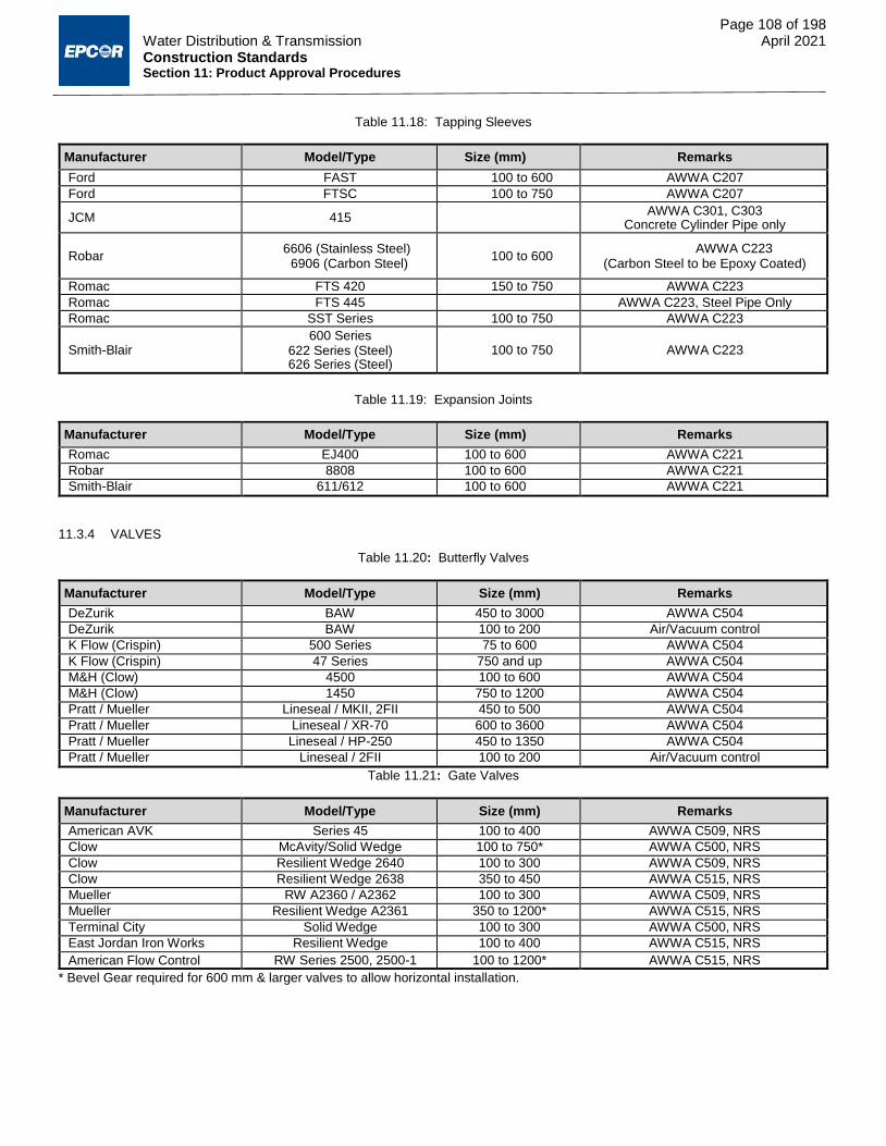
Page 108 of 198 Water Distribution & Transmission April 2021 Construction Standards Section 11: Product Approval Procedures
Table 11.18: Tapping Sleeves
Manufacturer Model/Type Size (mm) Remarks
Ford FAST 100 to 600 AWWA C207
Ford FTSC 100 to 750 AWWA C207
JCM 415 AWWA C301, C303
Concrete Cylinder Pipe only
Robar 6606 (Stainless Steel)
6906 (Carbon Steel) 100 to 600
AWWA C223 (Carbon Steel to be Epoxy Coated)
Romac FTS 420 150 to 750 AWWA C223
Romac FTS 445 AWWA C223, Steel Pipe Only
Romac SST Series 100 to 750 AWWA C223
Smith-Blair 600 Series
622 Series (Steel) 626 Series (Steel)
100 to 750 AWWA C223
Table 11.19: Expansion Joints
Manufacturer Model/Type Size (mm) Remarks
Romac EJ400 100 to 600 AWWA C221
Robar 8808 100 to 600 AWWA C221
Smith-Blair 611/612 100 to 600 AWWA C221
11.3.4 VALVES
Table 11.20: Butterfly Valves
Manufacturer Model/Type Size (mm) Remarks
DeZurik BAW 450 to 3000 AWWA C504
DeZurik BAW 100 to 200 Air/Vacuum control
K Flow (Crispin) 500 Series 75 to 600 AWWA C504
K Flow (Crispin) 47 Series 750 and up AWWA C504
M&H (Clow) 4500 100 to 600 AWWA C504
M&H (Clow) 1450 750 to 1200 AWWA C504
Pratt / Mueller Lineseal / MKII, 2FII 450 to 500 AWWA C504
Pratt / Mueller Lineseal / XR-70 600 to 3600 AWWA C504
Pratt / Mueller Lineseal / HP-250 450 to 1350 AWWA C504
Pratt / Mueller Lineseal / 2FII 100 to 200 Air/Vacuum control
Table 11.21: Gate Valves
Manufacturer Model/Type Size (mm) Remarks
American AVK Series 45 100 to 400 AWWA C509, NRS
Clow McAvity/Solid Wedge 100 to 750* AWWA C500, NRS
Clow Resilient Wedge 2640 100 to 300 AWWA C509, NRS
Clow Resilient Wedge 2638 350 to 450 AWWA C515, NRS
Mueller RW A2360 / A2362 100 to 300 AWWA C509, NRS
Mueller Resilient Wedge A2361 350 to 1200* AWWA C515, NRS
Terminal City Solid Wedge 100 to 300 AWWA C500, NRS
East Jordan Iron Works Resilient Wedge 100 to 400 AWWA C515, NRS
American Flow Control RW Series 2500, 2500-1 100 to 1200* AWWA C515, NRS
* Bevel Gear required for 600 mm & larger valves to allow horizontal installation.

Page 109 of 198 Water Distribution & Transmission April 2021 Construction Standards Section 11: Product Approval Procedures
Table 11.22: Check Valves
Manufacturer Model/Type Size (mm) Remarks
Mueller A 2600 / 52 SCS-1 100 to 300 -
Mueller A 2122 100 to 300 For Direct Bury Purposes
APCO Willamette 5800, 5800B 450 to 1500 -
APCO Willamette 9000, 9000L 100 to 1500 -
APCO Willamette 300 Series 100 to 250 -
APCO Willamette 600 Series 100 to 1050 -
APCO Willamette 100 Series 100 to 600 -
Table 11.23: Automatic Air Valves
Manufacturer Model/Type Size (mm) Remarks
APCO Willamette 50 Series 12 to 25 -
APCO Willamette 140 Series 10 to 75 -
APCO Willamette 143C to 151C 25 to 200 -
APCO Willamette 150 Series 100 to 750 -
APCO Willamette 200A Series 25, 50 -
ARI Flow Control Accessories K, S and D Models 20 to 50 NSF 61
Table 11.24: Manual Air Valves
Manufacturer Model/Type Size (mm) Remarks
Crane 438 15 to 80 Full Port Bronze Gate Valve
Crane 1701 6 to 80 Full Port Bronze Gate Valve
Boshart 814 15 to 100 Full Port Bronze Gate Valve
Newman Hattersly 33 15 to 50 Full Port Bronze Gate Valve
Jenkins 310J 15 to 80 Full Port Bronze Gate Valve
Kitz 40 10 to 50 Full Port Bronze Gate Valve
Nibco T - 113 8 to 80 Full Port Bronze Gate Valve
Toyo 206A 10 to 100 Full Port Bronze Gate Valve
Table 11.25: Pressure Reducing Valves
Manufacturer Model/Type Size (mm) Remarks
Singer 106 PR 100 to 400 or equivalent
Table 11.26: Flow Control Valves
Manufacturer Model/Type Size (mm) Remarks
Cla-Val Co. Hytrol 10 to 900 or equivalent

Page 110 of 198 Water Distribution & Transmission April 2021 Construction Standards Section 11: Product Approval Procedures
Table 11.27: Valve Casings and Middle Extensions
Manufacturer Model/Type Size (mm)
Remarks
Norwood Foundry Type B (Screw) - Conforms to Dwgs WA-003-001 to WA-003-005 Trojan Industries Type B (Screw) - Conforms to Dwgs WA-003-001 to WA-003-005 SIGMA Type B (Screw) - Conforms to Dwgs WA-003-001 to WA-003-005 Westview Sales Type B (Screw) - Conforms to Dwgs WA-003-001 to WA-003-005
Trojan Industries EPCORVBR - ## - Trojan part number is EPCORVBR- ## where ##
is the length in inches. Part name is EPCOR Extension Rod ##.
11.3.4.1 Back-Flow Preventers
11.3.4.1.1 Where backflow prevention is required, in accordance with the Plumbing Code of Canada, and the City
of Edmonton Waterworks Bylaw, backflow prevention devices shall be selected and installed in
compliance with CSA Manual B64 (current edition).
11.3.5 FIRE HYDRANTS
Table 11.28: Fire Hydrants
Manufacturer Model/Type Size (mm) Remarks
American AVK 2708 Nostalgic 150 AWWA C502
Mueller Canada Valve Century 150 AWWA C502
McCavity (Clow) Brigadier (M67) 150 AWWA C502
Mueller Modern Centurion 150 AWWA C502
East Jordan Iron Works Watermaster (5CD250) 150 AWWA C502
Note: Most suppliers offer a modern or a heritage style body, with the same working parts.
11.3.6 COATINGS AND LININGS
Table 11.29: Epoxy Coatings and Linings
Manufacturer Model/Type Size (mm) Remarks
3M Scotchkote 134 - AWWA C213 and C550
Table 11.30: Plant Coatings
Manufacturer Model/Type Size (mm) Remarks
Fusion Bonded Epoxy (FBE) - - AWWA C116, NSF 61
Shaw Pipe Yellow Jacket 1
External Coating Up to 600 Steel and DI Pipe

Page 111 of 198 Water Distribution & Transmission April 2021 Construction Standards Section 11: Product Approval Procedures
Table 11.31: Tape Coatings (Cold Applied)
Manufacturer Model/Type Size Remarks
Denso Primer and Tape - AWWA C217
Interprovincial Corrosion Control
Primer, Mastic and Tape - AWWA C217
Polyguard 600 Primer & Tape - AWWA C209
Polyken 1027 or 1029 Primer and 930 Tape - AWWA C209
Polyken YGIII Tape - AWWA C214
Premier Coating Primer and LT Tape - AWWA C217
Renfrew 327 Primer and 303-35 Tape - AWWA C209, C214
Royston 747 Primer and Greenline Tape - AWWA C209
Trenton Tec-Tape - AWWA C217
Advanced Corrosion Solutions
Tape, Mastic and Primer - AWWA C217-09
PCS Tape, Mastic and Primer - AWWA C217-09
Table 11.32: Heat-Shrinkable Sleeves (Exterior Protection – Joints/Flanges/Fittings)
Manufacturer Model/Type Size (mm) Remarks
Canusa - CPS Aqua - Shield - AWWA C216 NACE Std.
RP0303-2003
11.3.7 CATHODIC PROTECTION
Table 11.33: Cathodic Protection Weld Protection Materials
Manufacturer Model/Type Size (mm) Remarks
Royston Roybond 747 - -
Royston Handicap IP - -
Polyken 1027 - -
Polyken 931 - -
Polyguard 600 - -
KEMA 250-12 -
Same as KEMA 250 but with 12 mm polyethylene film on one side instead of being double sided adhesive.
KEMA 250 - -

Page 112 of 198 Water Distribution & Transmission April 2021 Construction Standards Section 11: Product Approval Procedures
Table 11.34: Cathodic Protection Splice Protection Materials
Manufacturer Model/Type Size (mm) Remarks
3M 8420 Series Cold Shrink
Connector - -
3M Scotchfil Putty - -
3M Scotch 130C Linerless Rubber
Splicing Tape - -
3M Super 33+ Vinyl Plastic Electrical
Tape - -
Raychem WCSM – 9/3 - -
11.3.8 MANHOLES
Table 11.35: Manhole Frames and Covers
Manufacturer Model/Type Size (mm)
Remarks
Norwood Foundry F-39 (Type 6A) - Must be marked “WATER” and include 2 – 25 mm
holes with plugs.
Trojan Industries TF-39 (Type 6A) - Must be marked “WATER” and include 2 – 25 mm
holes with plugs.
Norwood Foundry PM-A - Must be marked “WATER” and include 2 – 25 mm
holes with plugs.
Trojan Industries PM-A - Must be marked “WATER” and include 2 – 25 mm
holes with plugs.
Table 11.36: Alarms (Hatch)
Manufacturer Model/Type Size (mm) Remarks
Municipal Solutions HG (Hatch Guard) N/AP Remote intrusion alarm
11.3.9 MISCELLANEOUS
Table 11.37: Insulation
Manufacturer Model/Type Pipe Size (mm) Remarks
DOW HI-40 N/AP CAN/ULC-S701
25 mm to 100 mm thickness
Beaver Plastics Terrafoam HS40 N/AP CAN/ULC-S701
Expanded Polystyrene Up to 600 mm thickness
Owens Corning FOAMULAR 400 N/AP CAN/ULC-S701
25 mm to 100 mm thickness
Urecon Pre-Insulated Pipe 150 to 300 Rigid Polyurethane Coating Certain
restrictions apply
Urecon Spray On Insulation N/AP For chamber vault applications

Page 113 of 198 Water Distribution & Transmission April 2021 Construction Standards Section 11: Product Approval Procedures
Table 11.38: Pipe Casing Spacers
Manufacturer Model/Type Size (mm) Remarks
APS SIM 100 to 600 -
APS SI12 600 to 3000 -
BWM SS-8 100 to 600 Supplier: B&A Mfg.
BWM SS-12 750 to 1500 Sizes >900 Consult Factory
PSI Uni-Flange Restrained Casing
Spacers 100 to 600 ASTM A536, ASTM A242, AWWA C111
PSI Booster, A8GI, A12GI - -
PSI Ranger Midi 65 150 to 300 65 mm runner height only
Raci F Up to 528 O.D. -
Raci E Up to 2861 O.D. -
END OF SECTION

Construction Standards
Section 12 Water Meters
April 2021

Page 115 of 198 Water Distribution & Transmission April 2021 Construction Standards Section 12: Water Meters
12.1 GENERAL
12.1.1 SCOPE
12.1.1.1 This section covers material and installation requirements for water meters up to 600 mm in size.
12.1.2 PRODUCT ACCEPTANCE AND STANDARDS
12.1.2.1 Products are to be in accordance with recognized standards, such as AWWA, CSA, ASTM or ANSI.
12.1.2.2 Water meters are to comply with the following standards:
12.1.2.2.1 AWWA C700 - Cold Water Meters – Displacement Type, Bronze Main Case
12.1.2.2.2 AWWA C701 - Cold Water Meters – Turbine Type, for Customer Service
12.1.2.2.3 AWWA C703 - Cold Water Meters – Fire-Service Type
12.1.2.2.4 AWWA C706 - Direct-Reading, Remote-Registration Systems for Cold Water Meters
12.1.2.2.5 AWWA C707 - Encoder-Type Remote Registration Systems for Cold-Water Meters
12.1.2.2.6 AWWA C710 - Cold Water Meters – Displacement Type, Plastic Main Case
12.1.2.2.7 International Organization of Legal Metrology (OIML) Standard for Mag Meters
12.1.2.2.8 National Sanitation Foundation (NSF) Standard 14 - Plastics Piping System Components and Related
Materials
12.1.2.2.9 National Sanitation Foundation (NSF) Standard 61 - Drinking Water System Components - Health
Effects
12.1.2.2.10 National Sanitation Foundation (NSF) Standard 61 Annex G - 2008
12.1.2.2.11 Industry Canada (IC) Radio Standards Specification 102 (RSS-102) – Radio Frequency Exposure
Compliance of Radio Communication Apparatus (All Frequency Bands)
12.1.2.2.12 Industry Canada (IC) CPC-2-0-03 – Radio Communication and Broadcasting Antenna Systems
12.1.2.2.13 Health Canada (HC) – Radiofrequency Fields and Safety Code 6
12.1.2.2.14 Health Canada (HC) – Smart Meter Information
12.1.2.3 Compliance with a standard requires:
12.1.2.3.1 Certification from the supplier or manufacturer that the product meets the standard; and/or
12.1.2.3.2 Testing in accordance with a recognized procedure, such as the appropriate ASTM Standard.
12.1.3 QUALITY CONTROL
12.1.3.1 Retain certified copies of in-plant quality control test data. Provide copies to EPCOR if requested.
12.1.3.2 All water meters when supplied will have the contractor’s accuracy test results and serial numbers of each meter.
12.2 MATERIALS
12.2.1 WATER METERS
12.2.1.1 Water meters are to conform to the standards listed in Section 12.1.2 and Drawings WA-012-001to WA-012-008.
12.2.1.1.1 Direct bury electromagnetic flow meters to conform to Drawing WA-012-009.
12.2.1.2 The size, capacity and meter lengths for displacement type meters must conform to AWWA C700.
12.2.1.3 The size, capacity and meter lengths for turbine type meters must conform to AWWA C701.
12.2.1.4 The size, capacity and meter lengths for electromagnetic flow meters (mag meters) must conform to OIML
standards.
12.2.1.5 Suppliers must provide complete manuals complete with recommended installation procedures, a list of
replacement parts and prices, for all meters supplied.
12.2.1.6 All meters to have manufacturer’s accuracy test results and serial numbers of each meter included at the time of
delivery.
12.2.1.7 The main meter casing, including the inlet and outlet connections, are to be made of low-lead brass ( 0.25%
lead). Refer to NSF Standard 61 Annex G – 2008.
12.2.1.8 The meter size and direction of flow through the meter must be cast in raised characters on the body of the
meter.

Page 116 of 198 Water Distribution & Transmission April 2021 Construction Standards Section 12: Water Meters
12.2.1.9 Each meter must be identified by a unique 8 mm (5/16″) serial number, marked permanently on the outer meter
body.
12.2.1.10 Each meter must have a unique meter register identification code, which consists of six to ten digits.
12.2.1.10.1 Register codes must be electronically read from each individual meter register.
12.2.1.11 Each meter must have a unique encoder receiver transmitter (ERT) identification code, which consists of six to
ten digits.
12.2.1.12 The measuring meter chamber piston must not exceed 1160 nutations at 75 L/min, or 580 nutations at 37.8
L/min.
12.2.1.13 Encoder water meters must be comparable to:
12.2.1.13.1 The Sensus Technologies Incorporated touchpad; or
12.2.1.13.2 The Ellster C700 Invision style coder touchpad.
12.2.1.13.3 A pin type alignment is not acceptable.
12.2.1.14 Provide physical tamper detection and locking devices to all meters and meter registers.
12.2.1.15 Install grounding wires as per manufacturer’s specifications.
12.2.1.16 Registers for 50 mm to 150 mm (2" to 6") meters:
12.2.1.16.1 Single direct reading encoder type totalizing register per meter.
12.2.1.16.2 Encoder registers to measure cubic meters to six digits. Digits to be electronically read to the lowest ten
m3 values.
12.2.1.16.3 The digit on the right-hand side must represent a single m3 unit, i.e. one complete revolution of the test
dial indicator to increase the digit on the right-hand side by one m3.
12.2.1.17 Registers for 200 mm to 600 mm (8" to 24") meters:
12.2.1.17.1 Single direct reading encoder type totalizing register per meter.
12.2.1.17.2 Encoder registers shall have six digits measured in cubic metres, and a fixed zero. The fixed zero shall
represent zero to nine m3 values. Digits are to be electronically read to the lowest 100 m3 values.
12.2.1.17.3 All wheels and the fixed zero shall be in a white background with black numbering.
12.2.1.17.4 Test dials to be calibrated in one m3 values.
12.3 EXECUTION
12.3.1 Manufacturer’s Recommendations
12.3.1.1 Install according to the manufacturer’s recommendations. In case of discrepancy with these specifications, advise
EPCOR and request instruction before proceeding.
END OF SECTION

Construction Standards
Section 13 Concrete Requirements
April 2021

Page 118 of 198 Water Distribution & Transmission April 2021 Construction Standards Section 13: Concrete Requirements
13.1 SCOPE
13.1.1 Supply and installation of cement concrete for water structures and thrust blocks, excluding precast concrete.
13.2 RELATED SECTIONS
13.2.1 City of Edmonton Design and Construction Standards, Volume 2 – Complete Streets, Section 7.10 – Concrete Forms and Accessories
13.2.2 City of Edmonton Design and Construction Standards, Volume 2 – Complete Streets, Section 7.12 – Reinforcing Steel
13.3 QUALITY CONTROL
13.3.1 The Contractor shall retain and pay for the services of a testing laboratory to perform field tests on the concrete produced and installed. Testing shall be done in accordance with the most recent publication of CSA A23.1 and CSA A23.2. The minimum test requirements shall be:
13.3.1.1 Air content: Minimum once per day. Every batch delivered until air content is established to within specifications;
every third batch thereafter, unless specifications are not met, at which point the testing frequency shall revert to
one test per batch until satisfactory control is re-established.
13.3.1.1.1 For water mains ≥ 450 mm in diameter, the test frequency shall be increased to a minimum of 1 test per
each 25 m3 poured, with a minimum of one test per day of concrete placement.
13.3.1.2 Slump: Minimum once per day. Every batch delivered until specifications are met; every third batch thereafter.
13.3.1.2.1 For water mains ≥ 450 mm in diameter, the test frequency shall be increased to a minimum of 1 test per
each 25 m3 poured, with a minimum of one test per day of concrete placement.
13.3.1.3 Strength: In accordance with CSA-A23.2, standard tests for strength will be conducted at a frequency of not less
than one strength test for each 50 m3 (or part thereof) of concrete poured, with minimum of one test per project.
The standard strength test shall consist of three cylinders, laboratory moist cured, except when temperature is
below 5°C, when cylinders shall be field cured. Slump and air content taken with cylinders. One cylinder shall be
broken at 7 days, and two cylinders at 56 days.
13.3.1.3.1 For water mains ≥ 450 mm in diameter, the test frequency shall be increased to a minimum of 1 test per
each 25 m3 poured, with a minimum of one test per day of concrete placement.
13.3.1.4 Field cured cylinders: Two additional cylinders shall be cast when the ambient temperature is 5°C, or lower. Field
cured cylinders shall be cured on the job site under the same conditions as the concrete they represent. One
cylinder shall be broken at 7 days, and one cylinder at 56 days.
13.3.2 Failure to meet specifications shall result in the Engineer requesting, at the Contractor's cost:
13.3.2.1 Additional testing (coring, etc.)
13.3.2.2 Remedial work or replacement.
13.3.2.3 Other work as deemed necessary.
13.4 PRODUCTS
13.4.1 MATERIALS
13.4.1.1 Cement: to CSA-A3000, Type HS High sulphate-resistant
13.4.1.2 Aggregates: to CSA-A23.1
13.4.1.3 Water: to CSA-A23.1
13.4.1.4 Air Entraining Admixture: to ASTMC260
13.4.1.5 Chemical Admixture: to ASTM C494. Engineer to approve accelerating or set retarding admixtures during cold
and hot weather placing.
13.4.2 NON-SHRINK GROUT
13.4.2.1 Premixed compound consisting of non-ferrous aggregate, cement, water reducing and plasticizing agents,
capable of developing minimum compressive strength of 16.5 MPa at 2 days and 48 MPa at 28 days.
13.4.3 CURING COMPOUND
13.4.3.1 Non-membrane, colourless, non-yellowing chemical liquid curing compound conforming to CSA-A23.1 and to
ASTM C309.

Page 119 of 198 Water Distribution & Transmission April 2021 Construction Standards Section 13: Concrete Requirements
13.4.4 FLOOR HARDENER
13.4.4.1 Non-metallic, natural aggregate surface hardener.
13.4.5 BONDING AGENT
13.4.5.1 Two component, epoxy resin.
13.4.6 WATERSTOPS
13.4.6.1 PVC Waterstop: Extruded PVC of sizes as indicated in the drawings, to conform to CGSB 41-GP--35M.
Waterstop type and profile to be pre-approved by the Engineer.
13.4.7 DAMPPROOFING FOR WATER STRUCTURES
13.4.7.1 Consultant to submit dampproofing material specification for acceptance by the Engineer.
13.4.8 WATERPROOFING FOR WATER STRUCTURES
13.4.8.1 Consultant to submit cementitious waterproofing material specification for acceptance by the Engineer.
13.4.9 JOINT SEALANT
13.4.9.1 Control and expansion joints, on the interior and exterior of concrete walls as shown on drawings.
13.4.9.2 Sealant to CAN/CGSB-19.13 - one component, elastomeric, chemical curing sealing compound.
13.4.9.3 Refer to drawings for joint details and sealants for other joint types.
13.4.10 OTHER MATERIALS
13.4.10.1 All other materials, not specifically described but required for a complete and proper installation of all cast-in-
place concrete, shall be as selected by the Contractor subject to the approval of the Engineer.
13.4.11 MIX DESIGN
13.4.11.1 Mix design to be in accordance with CSA-A23.1, Table 5, it is the intent that the City follows Alternative 1 method
of specifying concrete. The concrete supplier assumes responsibility for the concrete mix proportions.
13.4.11.1.1 Upon request, the Contractor shall submit a mix design to the Engineer for review that will comply with
the requirements of these standards.
13.4.11.2 As a minimum, and unless specified by the Engineer elsewhere, for concrete used in water facilities, the
properties of the concrete shall be:
13.4.11.2.1 The minimum 56 day compressive strength requirement is 32 MPa.
13.4.11.2.2 The maximum water/cementing material ratio is 0.45.
13.4.11.2.3 Air content to be 4% to 7%.
13.4.11.2.4 The slump for concrete shall be 80 mm, ± 30 mm, unless specified elsewhere by the Engineer. The
specified slump for pumping of concrete may be increased with the use of superplasticizing admixtures,
upon approval of the mix design by the Engineer.
13.4.11.2.5 Maximum aggregate size of 20 mm, unless otherwise specified. Concrete density shall be normal.
13.4.11.3 Accelerating admixtures may be used in cold weather subject to approval of the Engineer. If approved, the use of
admixture will not relax the cold weather placement requirements. Use of calcium chloride shall not be permitted.
13.4.11.4 Set retarding admixtures may be used during hot weather to allow for proper finishing of concrete, subject to
approval of the Engineer.
13.4.11.5 The ratio of supplementary cementitious materials to total cementitious materials shall not exceed 0.20.
13.5 EXECUTION
13.5.1 DELIVERY OF CONCRETE
13.5.1.1 Concrete shall be delivered to the job site according to CSA-23.1 as supplemented or modified below.
13.5.1.2 The drum shall be rotated on the job site at mixing speed for three minutes just before discharge.
13.5.1.3 Water shall not be added after initial introduction of mixing water at the plant except when the slump at initial
discharge is less than specified.
13.5.1.3.1 If water is added, it is the responsibility of the supplier to ensure that the specified slump is not
exceeded, and the specified strength is attained.

Page 120 of 198 Water Distribution & Transmission April 2021 Construction Standards Section 13: Concrete Requirements
13.5.1.3.2 Slumps exceeding the specified slump will be a cause for rejection.
13.5.1.4 Re‐tempering with Air‐Entraining Admixtures is only permitted under the following conditions:
13.5.1.4.1 Re‐tempering on site with an approved air‐entraining admixture shall only be performed by a quality
control technician working for the concrete supplier. Dry, powdered, bagged or premeasured liquid air‐
entraining admixtures may be added by the concrete truck operator under the direction of the supplier’s
quality control technician. For re‐tempering purposes the concrete supplier shall use a comparable air‐
entraining admixture to what was originally approved for use in the mix design. Rotate the drum for 3 to
5 minutes or until the mix is uniform, after the addition of the air entraining admixture.
13.5.1.4.2 The quality assurance technician shall perform an air content test on each load of concrete retempered
with air‐entraining admixtures and shall immediately provide the test results to the Engineer.
13.5.1.4.3 Guidelines for re‐tempering with air‐entraining admixtures:
13.5.1.4.3.1 5.0 – 5.4 Addition of water or air‐entraining admixtures as deemed necessary by the supplier
to meet specifications.
13.5.1.4.3.2 4.0 – 4.9 Air‐entraining admixtures or air‐entraining admixtures and water must be added as
deemed necessary by the supplier to meet specifications.
13.5.1.4.3.3 < 3.9 No re‐tempering with air‐entraining admixtures or water is permitted; load will be
rejected.
13.5.1.4.4 When re‐tempering with air‐entraining admixtures, the supplier will be given one opportunity to meet the
specified air content.
13.5.1.4.5 When initial load requires re‐tempering, the quality assurance technician shall perform an air content test
to verify air content on subsequent loads until such time air content is acceptable.
13.5.1.4.6 If the need for re‐tempering with air‐entraining admixtures becomes persistent or continuous, the
Engineer or his representative may refuse to accept concrete loads that have been re‐tempered with air‐
entraining admixtures.
13.5.1.4.7 The use of de‐air-entraining admixtures is not permitted.
13.5.1.4.8 A load of concrete will be rejected if it is re‐tempered with air‐entraining admixtures and the resulting air
content exceeds the specified maximum air content.
13.5.1.4.9 A load of concrete that is rejected at the jobsite may not be re‐tempered at the concrete plant with
cement, aggregate, sand or admixtures and subsequently returned to the jobsite.
13.5.1.4.10 On site mix adjustments with cementitious materials, sand aggregate or any chemical admixtures other
than air‐entraining admixtures and superplasticizers will not be permitted.
13.5.1.5 The slump shall be measured in accordance with CSA-A23.2-5C.
13.5.1.6 The total air content shall be measured in accordance with CSA-A23.2-4C.
13.5.1.7 Concrete shall arrive at the work site with a temperature of not less than 10°C and not greater than 30°C.
13.5.1.8 Concrete shall be delivered to the site and discharged within two hours after introduction of the mixing water to
the cement and aggregates.
13.5.1.9 The delivery ticket shall show batch plant location, supplier's name, ticket and truck numbers, mechanically
punched date and time of initial plant mixing, mix design designation, water added, volume of concrete, site
arrival and discharge time and any other information requested by the Engineer.
13.5.1.10 Noncompliance of any of the requirements above shall be reasons for rejection of concrete by the Engineer.
13.5.2 PREPARATION
13.5.2.1 Obtain the Engineer's approval before placing concrete. Provide 24 hours’ notice prior to placing concrete.
13.5.2.2 Pumping of concrete is permitted only after approval of equipment and mix.
13.5.2.3 Ensure reinforcement and inserts are not disturbed during concrete placement.
13.5.2.4 Prior to placing of concrete obtain Engineer's approval of proposed method for protection of concrete during
placing and curing.
13.5.2.5 Maintain accurate records of poured concrete items to indicate date, location of pour, quality, and air temperature
and test samples taken.
13.5.2.6 Do not place load upon new concrete until authorized by the Engineer.
13.5.3 CONSTRUCTION
13.5.3.1 Do cast-in-place concrete work in accordance with CSA-A23.1.

Page 121 of 198 Water Distribution & Transmission April 2021 Construction Standards Section 13: Concrete Requirements
13.5.3.1.1 Formwork must be erected for all thrust blocks.
13.5.3.1.2 Dimensions of all thrust blocks are to be confirmed to match the specifications on the Engineering
Drawings.
13.5.3.1.3 Concrete is not to be poured over any fitting, except spool pieces with paddle flanges.
13.5.3.2 Sleeves and Inserts
13.5.3.2.1 No sleeves, ducts, pipes or other openings shall pass through joists, beams, column capitals or
columns, except where indicated or approved by the Engineer.
13.5.3.2.2 Where approved by the Engineer, set sleeves, ties, pipe hangers and other inserts and openings as
indicated or specified elsewhere. Sleeves and openings greater than 100 mm x 100 mm not indicated
shall be approved by the Engineer.
13.5.3.2.3 Do not eliminate or displace reinforcement to accommodate hardware. If inserts cannot be located as
specified, obtain approval of modifications from the Engineer before placing of concrete.
13.5.3.2.4 Check locations and sizes of sleeves and openings shown on drawings.
13.5.3.2.5 Set special inserts for strength testing as indicated and if required by non-destructive method of testing
concrete. Refer to Section 13.3.
13.5.3.3 Anchor Bolts
13.5.3.3.1 Set anchor bolts to templates under supervision of appropriate trade prior to placing concrete.
13.5.3.3.2 With approval of the Engineer grout anchor bolts in pre-formed holes or holes drilled after concrete has
set.
13.5.3.3.3 Protect anchor bolt holes from water accumulations, snow and ice build-ups.
13.5.3.3.4 Set bolts and fill holes with shrinkage compensating grout.
13.5.3.3.5 Grout under base plates and machinery using procedures in accordance with manufacturer's
recommendations which result in 100% contact over grouted area.
13.5.3.4 Waterstops
13.5.3.4.1 Install waterstops in all construction joints as shown on detailed drawings, or located below finished
grade.
13.5.3.4.1.1 Install them to provide a continuous water seal.
13.5.3.4.1.2 Do not distort or pierce waterstop in such a way as to hamper performance.
13.5.3.4.1.3 Do not displace reinforcement when installing waterstops.
13.5.3.4.2 Use only straight heat sealed butt joints in field. Use factory welded corners and intersections unless
otherwise approved by the Engineer.
13.5.3.4.3 All field splices to be inspected by the Engineer.
13.5.3.5 Joints
13.5.3.5.1 Locate and form all isolation or expansion joints as indicated on the Drawings.
13.5.3.5.1.1 Install joint filler, sealer and primer to manufacturer's instructions.
13.5.3.5.2 Install a polyethylene strip over joint filler to prevent bonding to joint sealer.
13.5.3.5.3 The Contractor shall submit a plan that shows the proposed location of joints and pour breaks to the
Engineer for approval.
13.5.3.5.4 Do not allow reinforcing steel to run through expansion joints or isolation joints unless otherwise
indicated.
13.5.3.6 Finishing
13.5.3.6.1 Finish concrete in accordance with CSA-A23.1.
13.5.3.6.2 Use procedures acceptable to the Engineer or those noted in CSA-A23.1 to remove excess bleed water.
13.5.3.6.3 Ensure surface is not damaged.
13.5.3.7 Floor Finishes
13.5.3.7.1 Finish and protect the top surface of all concrete as indicated on the Drawings or as specified below:
13.5.3.7.1.1 Plain Floor Finish (all covered floors and roof): 13.5.3.7.1.1.1 Finish concrete floors to CSA-A23.1 as specified below.
13.5.3.7.1.1.2 Use two passes of steel troweling to produce smooth burnished surface to within 5 mm
tolerance when measured in any direction using 3 m. straight edge.

Page 122 of 198 Water Distribution & Transmission April 2021 Construction Standards Section 13: Concrete Requirements
13.5.3.7.1.1.3 At areas with floor drains, maintain floors level at walls, pitch floor uniformly to drains at
a minimum rate of one half of one percent (5 mm per m) or as shown on the Drawings.
13.5.3.7.1.2 Hardened Floor Finish (all exposed floors): 13.5.3.7.1.2.1 Finish concrete floors per Section 13.5.3.7.1 and apply hardener at a rate specified by
the manufacturer.
13.5.3.7.1.3 Textured Non-Slip Finish (all exterior flatwork): 13.5.3.7.1.3.1 Immediately after first troweling of the "Plain Floor Finish", swirl-trowel, brush or broom
the surface to a uniformly textured non-slip finish, as described in CSA-A23.1.
13.5.3.8 Wall Finishes
13.5.3.8.1 In accordance with CSA-A23.1, leave concrete with a rough form finish for use on surfaces not exposed
to view in the structure. Chip off fins and irregular projections, and patch form tie holes.
13.5.3.8.2 For walls and surfaces exposed to view, the Contractor shall provide a sack rubbed finish as described
in CSA-A23.1
13.5.3.9 Protection and Curing
13.5.3.9.1 Cure all concrete in accordance with CSA-A23.1, Section 7.
13.5.3.9.2 Loosen wall forms within 24 hours as outlined in the City of Edmonton Design and Construction
Standards, Volume 2 – Complete Streets, Section 7.10 – Concrete Forms and Accessories.
13.5.3.9.3 Initial curing: ensure the concrete surface is kept continuously moist until the temperature produced by
the heat of hydration of the cement has peaked and dropped at least 8°C.
13.5.3.9.4 Final Curing: immediately after initial curing, additional curing shall be applied and maintained for a
period of 7 days, to ensure that the specified concrete strength and quality has been obtained.
13.5.3.9.5 Concrete thrust blocks must be cured a minimum of 3 days in the case of high early strength concrete or
a minimum of 7 days in the case of normal/sulphate resistant concrete prior to performing any
acceptance testing activities as described in Section 8.
13.5.3.10 Damp-proofing and Waterproofing of Drainage Structures
13.5.3.10.1 Apply damp-proofing compound to exterior of structural wall below grade where shown on drawings,
according to manufacturer's recommendations.
13.5.3.10.2 Apply waterproofing material onto interior surfaces of structural base and wall as indicated on drawings,
within 72 hours of stripping forms, and as recommended by the manufacture of the waterproofing
materials.
13.5.3.10.2.1 Cure the waterproofing compound as recommended by the manufacturer.
13.5.3.11 Repairing Concrete
13.5.3.11.1 Cut back metal form ties and voids not less than 20 mm from surface and fill with non-shrink grout.
13.5.3.11.2 Cut back honeycombed or defective areas perpendicular to the surface to a depth of 20 mm.
13.5.3.11.3 Brush on 1:1 cement sand grout over a saturated surface then patch with a 1:2 cement sand mortar with
10% hydrated lime.
13.5.3.11.4 Where honeycombing or defective areas require cut backs deeper than 50 mm, use non-shrink grout.
13.5.3.12 Bonding New Concrete to Old
13.5.3.12.1 Clean old concrete surface and protruding reinforcing steel concrete for a distance shown on detailed
drawings.
13.5.3.12.2 Roughen cleaned surfaces to expose the coarse aggregate of the existing concrete.
13.5.3.12.3 Immediately prior to placing new concrete, apply a coating of bonding agent to the existing surface, in
strict accordance with the manufacturer's recommendation.
13.5.3.12.4 In locations where new concrete is doweled to existing work, drill holes in existing concrete and insert
steel dowels and pack solidly with non-shrink grout to positively position and anchor dowels, or as
indicated on the drawings.
END OF SECTION

Volume 4 Water
Section 14 Detail Drawing Index
April 2021

Page 124 of 198 Water Distribution & Transmission April 2021 Construction Specifications Detail Drawing Index
New Drawing Number
Old Drawing Number
Description Approved
WA-002-001 2511-08 Insulation Requirements for Water Mains / Services April 2021
WA-002-002 2511-06 Typical Dead End up to 300 mm April 2021
WA-002-003 2511-11 Typical Flush Point Detail April 2021
WA-002-004 2512-20 Flush Point in Roadway (Shallow Chamber) April 2021
WA-002-005 2511-09 Flushmount Hydrant Detail April 2021
WA-002-006 2512-19 Blow Off Hydrant with Tipped Down Tee April 2021
WA-002-007 2511-03 Horizontal Concrete Thrust Block Details April 2021
WA-002-008a 2511-04 Vertical Bend Thrust Block Detail April 2021
WA-002-008b - Stainless Steel Clamp for Vertical Thrust Block Detail April 2021
WA-002-009 2511-13 Thrust Blocks for Reducers and Transition Couplings April 2021
WA-002-010 2511-12 Block and Rail Plug Detail April 2021
WA-002-011 2511-07 Typical Casing and Pipe with Spacer April 2021
WA-002-012 Net New Plastic Marker and Channel Post Detail April 2021
WA-002-013 Net New Soil Cell Structure Over Water Mains April 2021
WA-002-014 Net New Subdrain Installation Across Existing Water Mains April 2021
WA-003-001 2512-01 Valve Casing April 2021
WA-003-002 2512-02 Valve Casing Top Section and Plug April 2021
WA-003-003 2512-03 Valve Casing Middle Extensions April 2021
WA-003-004 2512-04 Valve Casing Bottom Section April 2021
WA-003-005 2512-05 Valve Bonnet April 2021
WA-003-006 2512-06 Valve Box Material Detail April 2021
WA-003-007 2512-07 Valve Box Construction Detail April 2021
WA-003-008 2512-08 Valve Casing Detail for Fillcrete Backfill April 2021
WA-003-009 2512-09 Valve Strapped to Tee Details April 2021
WA-003-010 2512-10 Valve Chamber Detail (Plan) April 2021
WA-003-011 2512-11 Valve Chamber Detail (Profile) April 2021
WA-003-012 2512-12 Automatic Air Valve Chamber Detail (Plan) (750 mm Mains and Smaller) April 2021
WA-003-013 2512-13 Automatic Air Valve Chamber Detail (Profile) (750 mm Mains and Smaller) April 2021
WA-003-014 2512-14 450 mm To 750 mm Direct Bury Butterfly Valve with Air Vents April 2021
WA-003-015 - 450 Gate Valve with Bevel Gearing & 50 Manual Air Vents April 2021
WA-003-016 2512-16 Typical 50mm Manual Air Vent in Roadway April 2021
WA-003-017 2512-17 Typical 50mm Manual Air Vent in Boulevard with 1.5m Separate Walk April 2021
WA-003-018 2512-18 Typical 50mm Manual Air Vent in Boulevard with 1.5m Monolithic Walk April 2021
WA-003-019 2512-21 Valve and Hydrant Requirements in Concrete Walk April 2021
WA-003-020 2512-22 Direct Bury Check Valve (300mm Diameter or Smaller) April 2021
WA-004-001 2513-01 Fire Hydrant Placement (Typical) April 2021
WA-004-002 - Deep Bury Fire Hydrant Placement (Typical) April 2021
WA-004-003 2513-02 Fire Hydrant Protection Placement April 2021
WA-004-004 - Fire Hydrant Hording Detail April 2021
WA-004-005 - Fire Hydrant Access Pad April 2021
WA-005-001 2514-01 50 mm & Smaller Copper Water Service April 2021
WA-005-002 2514-02 50 mm & Smaller Copper, Polymer, or Composite Water Service April 2021
WA-005-003 2514-03a Service Box Detail for 20mm, 25mm Water Service (Two Piece Casing) April 2021
WA-005-004 2514-03b Service Box Detail for 20mm, 25mm Water Service (One Piece Casing) April 2021
WA-005-005 2514-04a Service Box Detail for 40mm, 50mm Water Service (Two Piece Casing) April 2021
WA-005-006 2514-04b Service Box Detail for 40mm, 50mm Water Service (One Piece Casing) April 2021
WA-005-007 2514-09 Typical Single and Dual Service For New Developments April 2021

Page 125 of 198 Water Distribution & Transmission April 2021 Construction Specifications Detail Drawing Index
WA-005-008 2514-07 Typical Dual Service for Duplex / Semi-Detached Lots April 2021
WA-005-009 2514-10 100 mm to 300 mm Water Service for Unsuitable Foundation Condition (Building Abutting Property Line)
April 2021
WA-005-010 2514-11 100 mm to 300 mm Water Service for Unsuitable Foundation Condition (Building Removed from Property Line)
April 2021
WA-005-011a 2514-12a Water Servicing Requirements April 2021
WA-005-011b 2514-12b Water Servicing Requirements April 2021
WA-005-012 2514-13 Backflow Prevention for Private Service Looping April 2021
WA-005-013 Net New Curb Cock Location Stamp April 2021
WA-006-001 2511-02 Standard Trench Bedding for Circular Pipe April 2021
WA-007-001 2516-01 Anode Test Station Installation April 2021
WA-007-002 2516-02 Anode Installation – Exothermic Welding April 2021
WA-007-003 2516-03 Anode Installation at Hydrant & Connection to Existing Cast Iron Mains April 2021
WA-007-004 2516-04 Typical Anode Installation for Iron Fittings used with PVC Water Mains April 2021
WA-007-005 2516-05 Test Station Plug Detail April 2021
WA-007-006 2516-06 Anode on 50 mm and Smaller Copper Water Service April 2021
WA-007-007 2516-07 Cathodic Protection Exothermic Welding Components April 2021
WA-007-008 2516-08 Cathodic Protection – Test Station April 2021
WA-007-009 Net New Anode Installation - Pin Brazing April 2021
WA-012-001 2520-01 Specifications for Meter Settings Without Fire Protection System April 2021
WA-012-002 2520-02 Specifications for Meter Settings With Fire Protection System April 2021
WA-012-003 2520-03 Specifications for Meter Settings With Horizontal Bypasses April 2021
WA-012-004 2520-04 Specifications for Meter Settings With Vertical Bypasses April 2021
WA-012-005 2520-05 Specifications for Multiple Meters (Meter Bank) Without Fire Protection System
April 2021
WA-012-006 2520-06 Specifications for Multiple Meters (Meter Bank) With Fire Protection System April 2021
WA-012-007 2520-07 Specifications for Meter Settings With Fire Rink Service April 2021
WA-012-008 2520-08 Typical Installation of a 100 mm (4”) Water Meter April 2021
WA-012-009 2520-09 Electromagnetic Flow Meter Assembly April 2021

NOTES:
a: IW f-> o.O W(.) Cu.
0
HORIZONTAL
a:a: <(W -'> :::io zu ~ Cl 0 0 M
.----------------
W= L+2V
L MIN 150 - MAX 300 GRANULAR
V TO BE LESS THAN OR EQUAL TO L
INVERTED "U"
1. ALL DIMENSIONS ARE IN MILLIMETRES UNLESS OTHERWISE SPECIFIED. 2. APPLICABLE WHEN USING FILLCRETE, GRANULAR OR CLAY BACKFILL FOR
WATER MAINS WITH A DEPTH OF COVER LESS THAN THE MINIMUM, AS DESCRIBED IN THE DESIGN STANDARDS, SECTION 6.2.
3. USE DOW Hl-40 STYROFOAM BOARD, OR APPROVED EQUAL
~ z 0 ~
00 MIN 150 - MAX 300
a: GRANULAR ~~ wz
~:il
~ w >
MIN 150 - MAX 300 GRANULAR
z :il
>
'_) __ ~) (~-- STMORCULVERT (
W= L+2V W = W @ MIN (DOB, VS)
BOX
COVER DEPTH THICKNESS WIDTH (W) m mm {IN) m
1.1 -1.4 90 (3.5) 3.4
1.4 - 1.7 75 (3.0) 2.8
1.7-2.0 75 (3.0) 2.2
2.0 -2.3 50 (2.0) 1.6
2.3-2.9 40 (1 .5) 1.0
BELOW2.9 - -
INSULATION REQUIREMENTS FOR WATER MAINS/ SERVICES
APPROVED
APRIL 2021
SCALE
NTS
DRAWN BY
CWRIGHT
CHECKED BY
DMATHEW
DRAWING NUMBER
WA-002-001 OLD DRAWING NUMBER
2511-08

1/2 BEARING AREA AS PER DWG WA-002-007
VALVE TO BE CLOSED AND STOPPERED
PLUG WITH 50 THREADED HOLE
BACK OF WALK
Q'. UJ a.. a.. 8 0 U)
------ ------
PROPERTY LINE -------------NOTES: 1. ALL DIMENSIONS ARE IN MILLIMETRES UNLESS OTHERWISE SPECIFIED. 2. DESIGN BASIS:
a. HYDRAULIC PRESSURE 1034 kPa (150 psi}. b. SOIL BEARING CAPACITY 72 kPa (1500 lb/sq.ft) .
3. TEMPORARY BLOCKING MUST BE APPROVED BY THE ENGINEER. 4. CONCRETE STRENGTH SHALL BE 32 MPa AT 56 DAYS. 5. CONCRETE TO BE SULPHATE RESISTANT TYPE HS ACCORDING TO
THE MOST RECENT PUBLICATION OF CSA-A3000 UNLESS OTHERWISE APPROVED BY THE ENGINEER.
6. CONCRETE TO BE CLEAR OF BELLS. 7. CONCRETE TO BE PLACED UNDER ALL FITIINGS. 8. CONCRETE THRUST BLOCK REQUIRED FOR ALL FITIING. 9. BEARING SURFACE MUST BE ON UNDISTURBED SOIL UNLESS
OTHERWISE APPROVED BY THE ENGINEER.
1/2 BEARING AREA AS PER DWG WA-002-007
THRUST BLOCK
TYPICAL DEAD END UP TO 300mm
,___:_:_:-~-~-! E_~2-D1 ____ c_~-:-c-:-:-D H_BT-:y--< APPROVED • <' . ~ NTS D MATHew ~ATeR 01s,e,,cmo, A<O mANSMISSION
DRAWING NUMBER
WA-002-002 OLD DRAWING NUMBER
2511-06

MIN 1000 - MAX 3000 - +------------- MIN 4000 -------------
1 , MIN 300 I I -MAX 600 f---- MIN 1600 __ _.. __ _.._ ~~~iio _ _,_, ___ MIN 1500 -----i
WATER MAIN . <1 <1 ,•
4
,s,ecoGW>n<SOmm] }
4
THREADED HOLE
THRUST BLOCK
I
I I
I 50COPPER
PLAN VIEW
w z
\_'"'""I BLOCK
f------------- MIN 4000 -----------~
FOR CAP, OPERATING ROD AND CASING REFER TO DWG WA-005-006
WATER MAIN
COMPRESSION COUPLING THREADED INTO PLUG
NOTEES:
MIN 0.3 CU METRES OF 25 WASHED ROCK 300 DEEP
COVERED BY A LAYER OF 6 mil POLYETHYLENE
5.5 kG ZINC ANODE
50mm CC (SELF DRAINING) ON CAST IRON CHAIR ON
50x200x300 TREATED WOOD BLOCK
1. ALL DIMENSIONS ARE IN MILLIMETRES UNLESS OTHERWISE SPECIFIED. 2. BRAZED OR SILVER SOLDERED FIITINGS MAY BE REPLACED WITH
EPCOR APPROVED ALTERNATIVE. 3. ADJUST BOULEVARD DIMENSIONS BASED ON THE WALK SIZE.
90" BRAZED OR SILVER SOLDERED FIITING
SECTION
lw 1z ::;
,__ ___ MIN 1500 ----'1
/':
VALVE I~ PLUG Io
I &:
65 AMA ADAPTOR 65 MALE THREAD
BRAZED OR SILVER SOLDERED FIITING T050mm PIPE
50COPPER
VALVE BONNET
4 - 50x 150x300 TREATED WOOD SUPPORT BLOCKING FOR BONNET ON COMPACTED CLAY
CONCRETE THRUST BLOCK
TYPICAL FLUSH POINT DETAIL APPROVED
APRIL 2021
SCALE
NTS
DRAWN BY
CWRIGHT
CHECKED BY
DMATHEW
APPROVED
_ c- - - - - - - - - - - - - - - - - - - - - -RECTOR, WATER DISTRIBUTION AND TRANSMISSION
DRAWING NUMBER
WA-002-003 OLD DRAWING NUMBER
2511-11

~ THRUST BLOCK
l
NOTES:
FINISHED GRADE
150 PLUG WITH 50 THREADED HOLE r THRUST BLOCK
4 .. <1 4
COMPRESSION COUPLING THREADED INTO PLUG
1. ALL DIMENSIONS ARE IN MILLIMETRES UNLESS OTHERWISE SPECIFIED. 2. BRAZED OR SILVER SOLDERED FITIINGS MAY BE REPLACED WITH EPCOR
APPROVED ALTERNATIVE.
PLAN
MANHOLE COVER TYPE 6A FRAME AND COVER ~
50 COPPER PIPE
5.5 kg ZINC ANODE
PROFILE
/
50 MANUAL AIR VENT INSTALATION COMPLETE. SEE DWG WA-003-016
FLUSH POINT IN ROADWAY (SHALLOW CHAMBER) APPROVED
APRIL2021
SCALE
NTS
DRAWN BY
CWRIGHT
CHECKED BY
DMATHEW , WATER DISTRIBUTION AND TRANSMISSION
DRAWING NUMBER
WA-002-004 OLD DRAWING NUMBER
2512-20

)>
)>
(/)
"'O
-u
Z
O ~
jJ
-!
J>
r 0
v,
r f'\
l <
m
o
m
~
0
0 g
()
0 ;::
m
::E
~
)>
0 ;o
, ::E
....
;,;
:t
m
G1 z
mo
~
':11
::E
':1 "T
l r
)>
C
-u
(/)
-u
;o
:I:
0 <
m
Si:
0
0 C z ~ :I: -< 0 ::0
)>
z ~
0 m
~ r
0 r ~
o
0
I\.)
0
)>I
~~ I
-o
z
....>
.Z
OG
J I
G)
I\.)
z
Oz
I C
as
: (D
e o
rg
;::
CD u
, ;o
m
;o
~~
:-,I!'
> !'
.,ft
~~
~;-
"Z
-U O
O :0
()(I)
:0
;:E O
m CD
>8
ffi
~~
O~
R'.J
gfli~
~~
F!J
l C
:oo
Ei-
uo
;,;;
oo
c;,
;o .
. ~
illill:i
:J>
;:E
cn
mill~
;gl:
::
:j..
; _
, ~ ~
G)?
; o_
, J>
r ~
~~
~>
0~
F~
~~
/;;!
!!
00
~~
~6
::0
£0
0-u
~
"'T
1~
m~
~~
rn~
~~
~cn
~c
nt5~
rg~m
ofriQ
~ ~
:;;t
z~"'
~~
fnI:
:;!m
l; ~
en ...
. gic
i ;o
gi~
~O
Z
8>?,
;ffi-<
:O~<
oN!J
l!!;;
o-lr
OO
c::
!S:"
'TlQ
-r
PM
-A F
RA
ME
AN
D 8
05
CO
VE
R
WIT
H 2
• 2
5mm
HO
LE
S W
ITH
P
LUG
S A
ND
MA
RK
ED
"W
AT
ER
" O
R E
QU
IVA
LE
NT
cm
r~J>
~:i
i:t>
z~
C:
z;o
mc;:
: m
r-
1
S::
hirn
m~z
6cc•
~~~
lZiii i
d<
j: 2
00
~~
:to
;o
FL
US
HM
OU
NT
HY
DR
AN
T A
ND
OP
ER
AT
ING
N
UT
TO
BE
AS
CLO
SE
TO
CE
NT
ER
ED
IN
M
AN
HO
LE
BA
RR
EL
AS
PO
SS
IBL
E
-13
:>co
m
r o
m
0 J>
-u
:0 ;:
:-u Z
r f;;
;o O
en
;i!~
., ~ ~
:o£
cn
J>
~zC
m
::;1~
g
8m
}z-<
~~
~
-u~
~
~~
rn~
ill~
rn
00m
0 0
-<ID
mi;
;:cn
ocn
~~~
~~~~
~~6z
~ -U
o·
m:o
Q
mz
m
}o
;:
:~
~~
-<~
;o
~§3
~so
cl
~~
mo
-:o
m
:00
m
Oz
S::m
;!!
~
J>cn
C
D0
c;:
: z
"':o
-u
-<...,
S:
:m
GJ
~o
m
-<O
~~
en ~~Q
I..,
. 2
cn
>
o ~
m:i
: en
· z
0 m
m
m
=l
o J>
o
Z;:
: -<
;:E
-!
.
~£
z Ii;
~ m
-<
-< ffi
J>
;ll~
ffi O
~
0 (I
) m
.
z ....
GR
AD
E R
ING
S A
S R
EQ
UIR
ED
INS
TA
LL 1
00
(4")
CA
ML
OC
K C
OU
PL
ER
W
ITH
MA
LE
TH
RE
AD
IN
UN
LO
CK
ED
P
OS
ITIO
N &
100
(4"
) D
US
T P
LUG
HY
DR
AN
T A
ND
CA
PS
M
US
T B
E M
INIM
UM
10
0m
m
AB
OV
E W
AS
HE
D R
OC
K
90
0 B
AR
RE
L
-+I
WA
SH
ED
RO
CK
150
H
IGH
IN
SID
E R
ING
S
CO
MP
AC
TE
D G
RA
VE
L B
AS
E --
MIN
IMU
M 1
50 H
IGH
10
0m
m K
UP
FE
RL
E #
7600
-----,
MA
ING
UA
RD
FLU
SH
ING
H
YD
RA
NT
C/W
TY
PE
'B
' E
PO
XY
CO
AT
ED
RIS
ER
S
OR
AP
PR
OV
ED
EQ
UA
L
CO
MP
AC
TE
D C
LAY
OR
FIL
LCR
ET
E
UN
DE
RN
EA
TH
GR
AV
EL
BA
SE
MIN
IMU
M 1
50 S
AN
D
~
AB
OV
E W
AS
HE
D R
OC
K
150
µm (
6 m
il} L
AY
ER
O
F P
OL
YE
TH
YL
EN
E
MIN
IMU
M O
F 0
.3 C
UB
IC M
ET
RE
S
300
DE
EP
OF
25
WA
SH
ED
RO
CK
CO
NC
RE
TE
(25
MP
a)
TH
RU
ST
BL
OC
K
CO
NC
RE
TE
TO
BE
50
BE
LO
W
FLA
NG
E.
KE
EP
NU
TS
, B
OLT
S
AN
D
FL
AN
GE
S C
LEA
R O
F C
ON
CR
ET
E
AL
L D
RA
IN H
OL
ES
TO
B
E U
NO
BS
TR
UC
TE
D
AN
D F
RE
E T
O D
RA
IN
75
• 3
00
• 6
00
T
RE
AT
ED
RO
UG
H F
IR
HY
DR
AN
T S
EA
T
-----
MIN
10
00
-----
--,--- 1 I l I
1, ...
.. ,c
-r
.,;
,4,
•'
ic•
·~
ME
CH
AN
ICA
L J
OIN
T T
O
FIN
ISH
ED
GR
AD
E
• MANHOLE COV
ER
/ T
YP
E B
SC
RE
W T
YP
E C
AS
ING
/
AS
PE
R D
WG
WA
-003
-001
SE
E D
RA
WIN
GS
WA
-00
3-0
06
& W
A-0
03
-00
7 F
OR
VA
LV
E B
OX
DE
TA
IL
r CO
MP
AC
TE
D
CL
AY
MIN
IMU
M 3
00
mm
S
AN
D O
VE
R P
IPE
TR
AN
SM
ISS
ION
MA
IN
BE
LL
• 1
50 F
LG
TE
E T
IPP
ED
DO
WN
45°
."1
4
,i 4
,i
<>. 4
\
\_
"--
15
0/2
00
,45
'FL
GV
ER
TIC
AL
B
EN
D W
ITH
FLG
BE
LL
AD
AP
TE
R
CO
NN
EC
T T
O E
XIS
TIN
G O
UT
LE
T
ON
TR
AN
SM
ISS
ION
MA
IN
\ 5
00
< 1
00
TR
EA
TE
D B
LO
CK
ING
BE
WR
AP
PE
D I
N D
EN
SO
T
AP
E O
R A
PP
RO
VE
D E
QU
AL
EA
CH
SID
E S
UP
PO
RT
S V
AL
VE
IN
DE
PE
ND
EN
TL
Y O
F P
IPE
UN
TIL
C
ON
CR
ET
E I
S S
ET
.
CO
NC
RE
TE
TH
RU
ST
BL
OC
K
TO
BE
IM
BE
DD
ED
IN T
RE
NC
H W
AL
L

en
z ()
--4
)>
en
r m
()
0 I
;::
m
)>
()
--4 ~
Io
m
:E
~
)>
)>
"tl
"'O
:D
"'O
-:n
r
0 "'<
a
m
'::1 0
()
0
~ ~
15
z I
CJ
--4
-<
CJ
r 0 ~
0 'Tl
)>
'Tl
"'O l
I
~~
~~
m1
~
Z
:n
--i
~:~
~ ~
I ::J
I ~
I J>
I
zl o, --11 i1 en I
~I ~, ~I I 0 5
~o
1
\.)0
)>
i!:
0,i
!;
I :§
...... ::
;; o
z
I\JZ
O
Gl
I Gl
l\
,)Z
...
.>.
I C
c.o
~ as:
;::
0
~
~ 0
) :n
:n
--i
I --i
"U
"U
m
0 0 0 ~ z --i m
m
==--~
1\)....
1.z
~'nm
~~s
o~
mm
rm
io
oo
2~
~~~I
~ ~
z-c
n
~G>
~O
o~~B
i 0
66
)>
mo
o;o
,:
,t,.>
...,.m
:r88
z 0
-.,c
.,;::
i'
I ""T
1 "T
l i=
.,
,oo
r c;
a;al
::
;an
nm
.,
:Ol>
--4
~ts:
rfll
0:n
ocn
m
mo
c
~~o~
cn--
1"t
lm
~jje
i&i
~c~
O
;a:!.1
~:r
~~6~
!ll8i
:§
-i="m
cn
o;a
Dm
o
mcc
n
$!g~
ril
::;;:o
s::~
-m
m
z;:
:zm
G
>m
--4
~
~~
~
150µ
(6
MIL
) L
AY
ER
O
F P
OL
YE
TH
YL
EN
E
21
/2"
NO
ZZ
LE
CA
P T
O
BE
PA
RA
LL
EL
TO
RO
AD
MIN
IMU
M O
F 0
.3 C
UB
IC M
ET
ER
S
300
DE
EP
OF
25
WA
SH
ED
RO
CK
CO
NC
RE
TE
T
HR
US
T B
LO
CK
CO
NC
RE
TE
TO
BE
50m
m B
EL
OW
F
LA
NG
E N
UT
S O
N H
YD
RA
NT
VA
LV
E
75 X
300
X 6
00
T
RE
ST
ED
RO
UG
H F
IR
HY
DR
AN
T S
EA
T
gi
t------
900
MIN
-----
r 4
1/2"
PU
MP
ER
CA
P
TO
FA
CE
ST
RE
ET
WH
ITE
DIS
K (
SU
PP
LIE
D
BY
EP
CO
R)
TO
BE
IN
ST
AL
LE
D A
T
CO
MM
ISS
ION
ING
FIN
ISH
ED
GR
AD
E
lir ::i
TY
PE
B S
CR
EW
TY
PE
\
~·
•:
CA
SIN
G A
S P
ER
:
DW
G W
A-0
03-0
01
·
AL
L D
RA
IN H
OL
ES
T
O B
E U
NO
BS
TR
UC
TE
D
AN
D F
RE
E T
O D
RA
IN
RO
AD
WA
Y
TR
AN
SM
ISS
ION
MA
IN ~
BE
LL
x 1
50 F
LG T
EE
T
IPP
ED
DO
WN
45
•
SE
E D
RA
WIN
GS
WA
-00
3-0
06
&
WA
-00
3-0
07
FO
R V
AL
VE
BO
X D
ET
AIL
/
CO
MP
AC
TE
D C
LAY
r M
INIM
UM
300
mm
/
SA
ND
CO
VE
R
50 X
100
TR
EA
TE
D B
LO
CK
ING
S
UP
PO
RT
S V
AL
VE
IN
DE
PE
ND
AN
TL
Y
OF
PIP
E U
NT
IL C
ON
CR
ET
E I
S S
ET
CO
NC
RE
TE
TH
RU
ST
BL
OC
K T
O
BE
EM
BE
DD
ED
IN
TR
EN
CH
WA
LL
50 X
100
TR
EA
TE
D B
LO
CK
ING
S
UP
PO
RT
S V
AL
VE
IN
DE
PE
ND
AN
TL
Y
OF
PIP
E U
NT
IL C
ON
CR
ET
E IS
SE
T
150
FL
AN
GE
D A
DA
PT
OR
CO
NC
RE
TE
T
HR
US
T B
LO
CK

90° BEND
F
11.25° BEND
~ .
~r ' ·. .4 . ·.
SECTION F - F
45° BEND
G
SECTION G-G
TEE, DEAD END & VALVE
NOTES:
DIA(mm) 100 150 200 250 300 350
A(mm) 250 375 575 800 1025 925
B(mm) 125 175 200 225 250 375
AREA(m') 0.13 0.26 0.46 0.72 1.03 1.39
11 .25° BEND
DIA(mm) 100 150 200 250 300 350
A(mm) 50 100 150 175 225 275
B(mm) 125 150 175 200 225 250
AREA(m') 0.03 0.06 0.11 0.16 0.23 0.30
22.5° BEND
DIA(mm) 100 150 200 250 300 350
A(mm) 100 175 225 325 350 425
B(mm) 125 150 200 225 300 325
AREA (m2) 0.05 0.11 0.18 0.29 0.42 0.55
45° BEND
DIA(mm) 100 150 200 250 300 350
A(mm) 175 300 450 500 650 725
B(mm) 125 175 200 275 300 375
AREA(m') 0.09 0.21 0.36 0.55 0.78 1.09
90° BEND
DIA(mm) 100 150 200 250 300 350
A(mm) 325 525 BOO 925 1050 950
B(mm) 125 175 200 275 350 525
AREA(m') 0.16 0.37 0.64 1.02 1.47 2.00
FOR DEAD END PLUG THRUST BLOCK AND VALVE THRUST BLOCK SEE
DRAWING WA-002-002 OR WA-002-010
400
1025
450
1.85
400
325
275
0.41
400
450
400
0.72
400
875
400
1.40
400
1000
650
2.60
1. ALL DIMENSIONS ARE IN MILLIMETRES UNLESS OTHERWISE SPECIFIED. 2. DESIGN BASIS:
a. HYDRAULIC PRESSURE 1034 kPa (150 psi). b. SOIL BEARING CAPACITY 72 kPa (1500 lb/sq.ft).
3. TEMPORARY BLOCKING MUST BE APPROVED BY THE ENGINEER. 4. CONCRETE STRENGTH SHALL BE 32 MPa AT 56 DAYS. 5. CONCRETE TO BE SULPHATE RESISTANT TYPE HS ACCORDING TO
THE MOST RECENT PUBLICATION OF CSA-A3000 UNLESS OTHERWISE APPROVED BY THE ENGINEER.
6. CONCRETE TO BE CLEAR OF BELLS. 7. CONCRETE TO BE PLACED UNDER ALL FITTINGS. 8. CONCRETE THRUST BLOCK REQUIRED FOR ALL FITTING. 9. BEARING SURFACE MUST BE ON UNDISTURBED SOIL UNLESS
OTHERWISE APPROVED BY THE ENGINEER.
HORIZONTAL CONCRETE THRUST BLOCK DETAILS APPROVED
APRIL 2021
SCALE
NTS
DRAWN BY
CWRIGHT
CHECKED - BY
DMATHEW
APPROVED DRAWING NUMBER
WA-002-007 OLD DRAWING NUMBER
2511-03

DIA
SECTION Y-Y
u.
THREADED STAINLESS STEEL ROD
HEX NUT, WASHER AND JAM NUT
STAINLESS STEEL CLAMP -(SEE DWG WA-002--008b FOR DETAILS)
STAINLESS STEEL THREADED ANCHOR
ROD (D DIAMETER}
SECTION X-X
(.)
UNDISTURBED SOIL
PLACE CONCRETE AFTER ANCHOR BLOCK HAS BEEN POURED AND
BENDS SET IN PLACE
X ~ STAINLESS STEEL CLAMP
/ (SEE DWG WA--002-00Bb FOR DETAILS)
STAINLESS STEEL CLAMP ~ (SEE DWG WA-002-008b FOR DETAILS) \.
UP-THRUST BLOCK PROFILE
STAINLESS STEEL THREADED ANCHOR
ROD (D DIAMETER)
CONCRETE __/ ANCHOR BLOCK
SPACER BLOCK
STAINLESS STEEL THREADED ANCHOR ROD (D DIAMETER)
MINIMUM DIMENSIONS (mm)
PIPE SIZE A B C D
100 400 450 750 13
150 550 700 750 13
200 650 900 900 19
250 775 950 1100 19
300 1100 950 1100 25
350 1100 1100 1300 25
400 1225 1250 1350 25 NOTES: 1. ALL DIMENSIONS ARE IN MILLIMETRES UNLESS OTHERWISE SPECIFIED. 2. DESIGN BASIS:
a. HYDRAULIC PRESSURE 1034 kPa (150 psi}. b. SOIL BEARING CAPACITY 72 kPa (1500 lb/sq.ft}
3. TEMPORARY BLOCKING MUST BE APPROVED BY THE ENGINEER. 4. CONCRETE STRENGTH SHALL BE 32 MPa AT 56 DAYS. 5. CONCRETE TO BE SULPHATE RESISTANT TYPE HS ACCORDING TO
THE MOST RECENT PUBLICATION OF CSA-A3000 UNLESS OTHERWISE APPROVED BY THE ENGINEER.
6. CONCRETE TO BE CLEAR OF BELLS AND PIPE. 7. CONCRETE TO BE PLACED UNDER ALL FITIINGS. 8. CONCRETE THRUST BLOCK REQUIRED FOR ALL FITIINGS.
E
400
700
800
900
1000
1100
1350
9. BEARING SURFACE MUST BE ON UNDISTURBED SOIL UNLESS OTHERWISE APPROVED BY THE ENGINEER.
F G H J w T RQg~\~~D
650 700 80 300 64 9.5 0.25
725 800 80 300 64 9.5 0.57
900 1000 120 350 89 9.5 1.02
1000 1250 155 350 89 9.5 1.59
1175 1400 155 450 89 9.5 2.29
1350 1500 155 600 102 12.7 3.12
1450 1500 155 600 114 12.7 4.07
10. CONCRETE SHALL BE PLACED TO WITHIN 50mm OF THE FACE OF THE BELL. 11 . POL YETHEL YNE BOND BREAKER TO BE USED BETWEEN CONCRETE AND
FITIINGS. 12. THIS BLOCKING IS FOR BENDS UP TO 45° ONLY. 13. ALL BOLTS SHALL BE STAINLESS STEEL GRADE ASTM A 193 CLASS 1 BB.
NUTS SHALL BE GRADE A194 GRADE 8. 14. ALL OTHER STEEL SHALL BE STAINLESS STEEL GRADE ASTM A276 TYPE S304. 15. STAINLESS STEEL TO BE FABRICATED BY A SHOP CERTIFIED BY THE
CANADIAN WELDING BUREAU TO THE REQUIREMENTS OF CSA-W47.1, DIVISION 1 OR 2.1 ONLY. WELDING TO CONFORM TO CSA-W59.1 STANDARD REQUIREMENTS.
16. CLAMP TO REST ON BELL OF PVC FITIINGS AND ON FITIING BODY FOR CAST IRON OR DUCTILE IRON FITIINGS.
17. FOR EACH SET OF CLAMPS, THE BOLT PATIERN SHALL BE REVERSED.
VERTICAL BEND THRUST BLOCK DETAIL APPROVED
APRIL2021
SCALE
NTS
DRAWN BY
CWRIGHT
CHECKED BY
DMATHEW
DRAWING NUMBER
WA-002-00Ba OLD DRAWING NUMBER
2511-04

6.4mm THICK NEOPRENE PAD
STAINLESS STEEL CLAMP FABRICATED FROM A SINGLE
PIECE OF PLATE STEEL
SPRINGLINE
INSIDE RADIUS OF CLAMP TO MATCH OUTSIDE RADIUS OF FITTING PLUS PAD THICKNESS
STAINLES STEEL ANCHOR ROD _ _.2~;"';tb~f.t'! STAINLESS STEEL GUSSET TWO STAINLESS STEEL
NUTS c/w WASHER
r CLAMP
BOLT HOLE POSITION 2
MINIMUM DIMENSIONS (mm)
PIPE SIZE A B C D
100 400 450 750 13
150 550 700 750 13
200 650 900 900 19
250 775 950 1100 19
300 1100 950 1100 25
350 1100 1100 1300 25
400 1225 1250 1350 25
NOTES: 1. ALL DIMENSIONS ARE IN MILLIMETRES UNLESS OTHERWISE SPECIFIED. 2. DESIGN BASIS:
a. HYDRAULIC PRESSURE 1034 kPa (150 psi). b. SOIL BEARING CAPACITY 72 kPa (1500 lb/sq.fl)
3. TEMPORARY BLOCKING MUST BE APPROVED BY THE ENGINEER. 4. CONCRETE STRENGTH SHALL BE 32 MPa AT 56 DAYS. 5. CONCRETE TO BE SULPHATE RESISTANT TYPE HS ACCORDING TO
THE MOST RECENT PUBLICATION OF CSA-A3000 UNLESS OTHERWISE APPROVED BY THE ENGINEER.
6. CONCRETE TO BE CLEAR OF BELLS AND PIPE. 7. CONCRETE TO BE PLACED UNDER ALL FITTINGS. 8. CONCRETE THRUST BLOCK REQUIRED FOR ALL FITTINGS.
E
400
700
800
900
1000
1100
1350
9. BEARING SURFACE MUST BE ON UNDISTURBED SOIL UNLESS OTHERWISE APPROVED BY THE ENGINEER.
F G H J w T REQUIRED VOLCm'l
650 700 80 300 64 9.5 0.25
725 800 80 300 64 9.5 0.57
900 1000 120 350 89 9.5 1.02
1000 1250 155 350 89 9.5 1.59
1175 1400 155 450 89 9.5 2.29
1350 1500 155 600 102 12.7 3.12
1450 1500 155 600 114 12.7 4.07
10. CONCRETE SHALL BE PLACED TO WITHIN 50mm OF THE FACE OF THE BELL. 11 . POL YETHEL YNE BOND BREAKER TO BE USED BETWEEN CONCRETE AND
FITTINGS. 12. THIS BLOCKING IS FOR BENDS UP TO 45° ONLY. 13. ALL BOLTS SHALL BE STAINLESS STEEL GRADE ASTM A 193 CLASS 1 B8.
NUTS SHALL BE GRADE A194 GRADE 8. 14. ALL OTHER STEEL SHALL BE STAINLESS STEEL GRADE ASTM A276 TYPE S304. 15. STAINLESS STEEL TO BE FABRICATED BY A SHOP CERTIFIED BY THE
CANADIAN WELDING BUREAU TO THE REQUIREMENTS OF CSA-W47.1, DIVISION 1 OR2.1 ONLY. WELDING TO CONFORM TO CSA-W59.1 STANDARD REQUIREMENTS.
16. CLAMP TO REST ON BELL OF PVC FITTINGS AND ON FITTING BODY FOR CAST IRON OR DUCTILE IRON FITTINGS.
17. FOR EACH SET OF CLAMPS, THE BOLT PATTERN SHALL BE REVERSED.
STAINLESS STEEL CLAMP FOR VERTICAL THRUST BLOCK DETAIL
APPROVED
APRIL2021
SCALE
NTS
DRAWN BY
CWRIGHT
CHECKED BY
D MATHEW TOR, WATER DISTRIBUTION AND TRANSMISSION
DRAWING NUMBER
WA-002-00Bb OLD DRAWING NUMBER
2511-04

C
1/2 BEARING AREA
1/2 BEARING AREA
C
PIPE TO BE CENTERED IN THRUST BLOCK
1/2 BEARING AREA
SECTION C-C
OPTION 1: KEY INTO TRENCH WALL
D
L,...,,--+---~
D
"' .... z ~
SECTION D-D
OPTION 2: KEY INTO TRENCH FLOOR
IPS = IRON PIPE SIZE AC ME = ASBESTOS CEMENT MACHINED END AC BL = ASBESTOS CEMENT BAREL Cl OD = CAST IRON OUTSIDE DIAMETER
TRANSITION COUPLINGS (Cl OD TO OTHER)- Required bearing area in sq. m
Cl OD to: 600 500 450 400 350 300 250 200 150 100
IPS 0.65 0.49 0.41 0 .35 0.26 0.09 0.09 0.09 0.09 0.09
ACME 0.65 0.55 0.43 0 .26 0.21 0.15 0.10 0.09 0.09 0.09 REDUCERS
ACBL 0.96 0.64 0.47 0 .42 0.33 0.21 0.15 0.09
NOTES: 1. ALL DIMENSIONS ARE IN MILLIMETRES UNLESS OTHERWISE SPECIFIED. 2. DESIGN BASIS:
i. HYDRAULIC PRESSURE 1034 kPa (150 psi) ii. SOIL BEARING CAPACITY 72 kPa (1500 lb/sq . ft)
3. TEMPORARY BLOCKING MUST BE APPROVED BY THE ENGINEER. 4. CONCRETE STRENGTH SHALL BE 32 MPa AT 56 DAYS. 5. CONCRETE TO BE SULPHATE RESISTANT TYPE HS ACCORDING TO
THE MOST RECENT PUBLICATION OF CSA-A3000 UNLESS OTHERWISE APPROVED BY THE ENGINEER.
6. CONCRETE TO BE CLEAR OF BELLS AND PIPE. 7. CONCRETE TO BE PLACED UNDER ALL FITTINGS. 8. CONCRETE THRUST BLOCK REQUIRED FOR ALL FITTINGS. 9. BEARING SURFACE MUST BE ON UNDISTURBED SOIL UNLESS
OTHERWISE APPROVED BY THE ENGINEER. 10. REQUIRED BEARING AREA CAN BE ACHIEVED BY KEYING INTO
TRENCH WALL OF FLOOR.
0.09 0.09 SMALL PIPE LARGE PIPE
A(mm) B(mm) DIA(mm) DIA(mm)
100 150 300 250 100 200 350 500 150 200 350 300 150 250 400 575 200 250 400 325 200 300 450 650 250 300 450 350 250 350 500 700 300 350 500 375 300 400 550 725 350 400 550 400
1/2 BEARING AREA
REQUIRED BEARING AREA(m')
0.14 0.34 0.20 0.45 0.25 0.56 0.31 0.68 0.37 0.79 0.42
THRUST BLOCKS FOR REDUCERS AND TRANSlTION COUPLING
APPROVED
APRIL 2021
SCALE
NTS
DRAWN BY
CWRIGHT
CHECKED BY
DMATHEW WATER DISTRIBUTION AND TRANSMISSION
DRAWING NUMBER
WA-002-009 OLD DRAWING NUMBER
2511-13

WATERMAIN ~
---A---o;
r t)
300 CLEAR
\_ UNDISTURBED SOIL
DWG WA-002-003
PLAN VIEW
r CONCRETE ANCHOR BLOCK
. <1
<I
ELEVATION
NOTES: 1. ALL DIMENSIONS ARE IN MILLIMETRES UNLESS OTHERWISE SPECIFIED. 2. CONCRETE STRENGTH SHALL BE 32 MPa AT 56 DAYS. 3. CONCRETE TO BE CLEAR OF BELLS AND PIPE. 4. CONCRETE TO BE SULPHATE RESISTANT TYPE HS ACCORDING TO
THE MOST RECENT PUBLICATION OF CSA-A3000 UNLESS OTHERWISE APPROVED BY THE ENGINEER.
5. DIMENSIONS A, B & C TO BE PROVIDED ON THE ENGINEERING DRAWINGS.
BLOCK AND RAIL PLUG DETAIL APPROVED DRAWN BY APPROVED ~ /7 APRIL 2021 C WRIGHT ~ ,.....- ;!5--
1----S-C-A-LE---+--C-HE_C_K_E_D_B_Y----;
NTS D MATHEW DI ECTOR, WATER DISTRIBUTION AND TRANSMISSION
DRAWING NUMBER
WA-002-010 OLD DRAWING NUMBER
2511-12
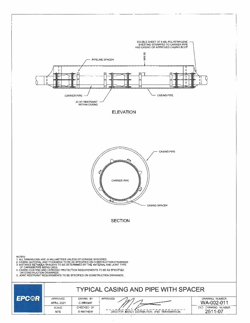
PIPELINE SPACER
CARRIER PIPE
JOINT RESTRAINT WITHIN CASING
DOUBLE SHEET OF 6 MIL POLYETHYLENE SHEETING STRAPPED TO CARRIER PIPE
AND CASING OR APPROVED CASING BOOT
\_ CASING PIPE
ELEVATION
CARRIER PIPE
SECTION
NOTES: 1. ALL DIMENSIONS ARE IN MILLIMETRES UNLESS OTHERWISE SPECIFIED. 2. CASING MATERIAL AND THICKNESS TO BE AS SPECIFIED ON CONSTRUCTION DRAWINGS. 3. DISTANCE BETWEEN SPACERS TO BE DETERMINED BY THE MATERIAL AND JOINT TYPE
OF CARRIER PIPE BEING USED. 4. CASING COATING AND CATHODIC PROTECTION REQUIREMENTS TO BE AS SPECIFIED
ON CONSTRUCTION DRAWINGS. 5. JOINT RESTRAINT REQUIREMENTS TO BE SPECIFIED ON CONSTRUCTION DRAWINGS.
CASING SPACER
TYPICAL CASING AND PIPE WITH SPACER APPROVED DRAWN BY APPROVED ~
f--A_P_R_IL_2_0_2_1 ____ c_w_R_IG_H_T_--I • • . ~:::::::o-i;;::::::-----SCALE CHECKED BY ~ NTS D MATHEW DIRECTOR, ~TER DISTRIBUTION AND TRANSMISSION
DRAWING NUMBER
WA-002-011 OLD DRAWING NUMBER
2511-07

MARKERCAP ~ (SEE DETAIL) '\.
r I II
BRING UP TRACER WIRE TO CONNECT
WATER DECAL (SEE DETAIL)
PLASTIC MARKER MARKER RHINO BLUE TRIVIEW INSTALLED OVER LI-CHANNEL POST
TRACER WIRE
EXISTING GROUND ~
_)_-l--f--+ttf hl~---4-----
N
"'
II ii II ii II 11 II ii II ii
!ii ~ --' w z ~ :I:
0 y "' =>
Jj GROUNDING ANODE ROD
__________ __;::::===~~ 8 GAUGE LEAD TRACER WIRE THROUGH MARKER.
6 BRING UP APPROXIMATELY 3.0m ABOVE GROUND
WATER MAIN
--------------~
PROFILE
TO ENSURE TRACER WIRE CAN CONNECT TO TERMINAL BOARD AT TOP OF MARKER
NOTE: ALL DIMENSIONS ARE IN MILLIMETRES UNLESS OTHERWISE SPECIFIED.
MARKER CAP DETAIL
LABEL CONNECTIONS WITH PERMANENT MARKER
I
0
\ \
BACK
GROUNDING WIRE
0 GROUND
FRONT
TERMINAL BOARD DETAIL
p w• AP yE EL R~
E
CALL EPCOR DISPATCH
780412-4500
WATER DECAL DETAIL
PLASTIC MARKER AND CHANNEL POST DETAIL APPROVED
APRIL2021
SCALE
NTS
DRAWN BY
CWRIGHT
CHECKED BY
DMATHEW
DRAWING NUMBER
WA-002-012 OLD DRAWING NUMBER

NOTE:
0 0
"'
0 g z :;,
Nlv-1 oom
1. ALL DIMENSIONS ARE IN MILLIMETRES UNLESS OTHERWISE SPECIFIED.
Cl
! (!) z i5 Cl UJ CD
en z < ::E Cl'. w
i C) z i== en x w w
6 co <(
z 0
~ -'
~ ~ -' -' w (.)
-' 0 en
SOIL CELL STRUCTU.RE OVER WATER MAINS APPROVED
APRIL2021
SCALE
NTS
DRAWN BY
CWRIGHT
CHECKED BY
DMATHEW
DRAWING NUMBER
WA-002-013 OLD DRAWING NUMBER

NOTES:
APPROVED PIPE SUPPORT MATERIAL (COMPACTED CLAY OR FILCRETE)
I --1
MIN 1500
SUBDRAIN INSTALLATION ACROSS EXISTING WATER MAINS
1. ALL DIMENSIONS ARE IN MILLIMETRES UNLESS OTHERWISE SPECIFIED. 2. INSULATION AS PER DWG WA-002-001 AS REQUIRED.
SUBDRAIN INSTALLATION ACROSS EXISTING WATER MAINS
1---~: P_p:_~_~ 2_v~-~-1~+--~~-~_:_~_H_B;~--l APPROVED~~
SCALE CHECKED BY ;;?:~Z::::::::::l,:--~~~~-NTS D MATHEW DIR TOR, WATER DISTRIBUTION AND TRANSMISSION
DRAWING NUMBER
WA-002-014 OLD DRAWING NUMBER

MIDDLE SECTION PER WA-003-003 MAY BE ~ USED IF APPROVED BY THE ENGINEER
PRIOR TO COMMENCING INSTALLATION
NOTES: 1. ALL DIMENSIONS ARE IN MILLIMETRES UNLESS OTHERWISE SPECIFIED. 2. MINIMUM 300mm OF THREADS AVAILABLE FROM TOP SECTION TO
BOTIOM SECTION FOR RAISING AND LOWERING.
APPROVED
APRIL2021
SCALE
NTS
DRAWN BY
CWRIGHT
CHECKED BY
D MATHEW
APPROVED
PLUG
. ....
TOP SECTION
·. ~ :
-.... ..
BOTIOM SECTION
BONNET
MANUFACTURING TOLERANCES: ± 2mm FOR INDICATED CASTING DIMENSIONS OF 190mm OR LESS. ± 3mm FOR INDICATED CASTING DIMENSIONS OF 191mm TO 280mm. ± 4mm FOR INDICATED CASTING DIMENSIONS OF 281mm TO 380mm.
VALVE CASING DRAWING NUMBER
--- 'A _____ : __ Tffi DISTRIBUTION AND TRANSMISSION
WA-003-001 OLD DRAWING NUMBER
2512-01

B
It) N
L t
...J
TOP VIEW
oeo1 ; ~ J45L
[115]
180
CROSS SECTION "B - B"
PLUG
t 0 It)
,-----164----
CROSS SECTION "A-A" NOTES:
B
1. ALL DIMENSIONS ARE IN MILLIMETRES UNLESS OTHERWISE SPECIFIED. 2. L (LENGTH) SIZES ARE 600, 900 AND 1200mm. 3. PLUG: DUCTILE IRON TO ASTM 536 GRADE 6040-18. 4. MINIMUM 300mm OF THREADS AVAILABLE FROM TOP SECTION TO
BOTIOM SECTION FOR RAISING AND LOWERING.
NOTCH CUT BACK TO WALL OF PIPE
PLUG HOLDER
"' ....
0 0
"'
A
TOP VIEW
t4------ 220 ------
I I I / 'T-1- - - - - - - - --,-r:
I I r-- --- I ~- -I L -,
11....-1~-~-~~-~~--~~I
~-- ---- ----- I f4+--r-----"----:_,.....?oo --'-"--.,,--'T-+--i
I i--r--_ ~-L
I --f---r- -L_
-.., --..J
---J I
-, --i
--- --- I
- ----=, I -- -- -,
~==--=----===~ ~- i L - - -, I -~ r-- --.J r-_ - ---- I L I 1. -- - --i ,--- -- --..J 1- - - - --._ - - - - - I __ _,
ELEVATION
MANUFACTURING TOLERANCES:
A
THREADS HAVE A40mmSLOT
± 2mm FOR INDICATED CASTING DIMENSIONS OF 190mm OR LESS. ± 3mm FOR INDICATED CASTING DIMENSIONS OF 191mm TO 280mm. ± 4mm FOR INDICATED CASTING DIMENSIONS OF 281mm TO 380mm.
VALVE CASING TOP SECTION AND PLUG APPROVED
APRIL2021
SCALE
NTS
DRAWN BY
CWR~~-=-
CHECKED BY
DMATHEW
APPROVED~~;:;;;;;.=-0::::~=-~~~
- ~~,~ISTRIBUTION AND TRANSMISSION
DRAWING NUMBER
WA-003-002 OLD DRAWING NUMBER
2512-02

118 t ...
M
_i
I FIT ACME THREAD _j L 50 _j l---164__j
NOTES: 1. ALL DIMENSIONS ARE IN MILLIMETRES UNLESS OTHERWISE SPECIFIED. 2. L (LENGTH) SIZES ARE 600, 900 AND 1200mm. 3. PLUG: DUCTILE IRON TO ASTM 536 GRADE 60-40-18. 4. MINIMUM 300mm OF THREADS AVAILABLE FROM TOP SECTION TO
BOTTOM SECTION FOR RAISING AND LOWERING.
;?
L I
ACME THREAD ro 14.5" ~ --, L
l--10J
20-i r
MANUFACTURING TOLERANCES: ± 2mm FOR INDICATED CASTING DIMENSIONS OF 190mm OR LESS. :t 3mm FOR INDICATED CASTING DIMENSIONS OF 191mm TO 280mm. :t 4mm FOR INDICATED CASTING DIMENSIONS OF 281mm TO 380mm.
VALVE CASING MIDDLE EXTENSIONS APPROVED
APRIL2021
SCALE
NTS
DRAWN BY
CWRIGHT
CHECKED BY
D MATHEW , Wl>.TER DISTRIBUTION AND TRANSMISSION
DRAWING NUMBER
WA-003-003 OLD DRAWING NUMBER
2512-03

A
TOP VIEW
...J
fr( N f------ 181 -----i
0
ELEVATION
NOTES:
A
LO 0 N~
1. ALL DIMENSIONS ARE IN MILLIMETRES UNLESS OTHERWISE SPECIFIED. 2. L (LENGTH) SIZES ARE 900, 1200 AND 1500mm. 3. MINIMUM 300mm OF THREADS AVAILABLE FROM TOP SECTION TO
BOTTOM SECTION FOR RAISING AND LOWERING.
D = 215
CROSS SECTION "B - B"
CROSS SECTION "A -A"
MANUFACTURING TOLERANCES:
.l ,._ M
t
± 2mm FOR INDICATED CASTING DIMENSIONS OF 190mm OR LESS. ± 3mm FOR INDICATED CASTING DIMENSIONS OF 191mm TO 280mm. ± 4mm FOR INDICATED CASTING DIMENSIONS OF 281mm TO 380mm.
VALVE CASING BOTTOM SECTION APPROVED
APRIL2021
SCALE
NTS
DRAWN BY
CWRIGHT-
CHECKED BY
DMATHEW
APPROVED
:2 -~---- ,-,,,. __ 5 _________ _ CTOR, WATER DISTRIBUTION AND TRANSMISSION
DRAWING NUMBER
WA-003-004 OLD DRAWING NUMBER
2512-04

A A
1..!:~=::::::;;=:;"7' tt:..====S~
CROSS SECTION "B - B"
--------- 395 ---------
NOTES:
TOP VIEW
---- 180 ___ ,...
+ TOPOF VALVE NUT
CROSS SECTION "A-A"
1. ALL DIMENSIONS ARE IN MILLIMETRES UNLESS OTHERWISE SPECIFIED. 2. MATERIAL: DUCTILE IRON TO ASTM 536 GRADE 60-40-18.
MANUFACTURING TOLERANCES: ± 2mm FOR INDICATED CASTING DIMENSIONS OF 190mm OR LESS. ± 3mm FOR INDICATED CASTING DIMENSIONS OF 191mm TO 280mm. ± 4mm FOR INDICATED CASTING DIMENSIONS OF 281mm TO 380mm.
VALVE BONNET APPROVED
APRIL2021
SCALE
NTS
DRAWN BY
CWRIGHT
CHECKED BY
DMATHEW
Zc----- ,. ~ __ .. -------------
DRAWING NUMBER
WA-003-005 OLD DRAWING NUMBER
2512-05

-I I 0 0 I I o 0
I I I I
0 0 I I 0
I I 0
0
0 0
<C 0
0
0 01 I 0 0
I I I I
0 I I 0 0
0 I I
610 ,-
PLAN VIEW
f.o,------ 610 ------,-r 184 1 1 184---Jl.__1
bJJTAZ~ wzzmj, -i-
FRONTVIEW
NOTES: 1. ALL DIMENSIONS ARE IN MILLIMETRES UNLESS OTHERWISE SPECIFIED. 2. SEE ALSO DRAWING WA-003-007.
CONSTRUCTED FROM 38mm x 184mm CONSTRUCTION GRADE LUMBER (SPRUCE, PINE, FIR)
ALL WOOD MEMBERS ARE TO BE TREATED WITH GREEN COPPERWOOD PRESERVATIVE #580025
USE 89mm COATED NAILS (3 ~")
------- 610 -------i
I.I/ Ol1/Ji1
FRONT VIEW
VALVE BOX MATERIAL DETAIL APPROVED
APRIL2021
SCALE
NTS
DRAWN BY
CWRIGHT
CHECKED BY
DMATHEW
DRAWING NUMBER
WA-003-006 OLD DRAWING NUMBER
2512-06

NOTE:
0 ' / 50X100 BLOCKING SUPPORTS y
VALVE INDEPENDENTLY OF PIPE UNTIL CONCRETE IS SET UP
CONCRETE THRUST BLOCK TO BE EMBEDDED IN TRENCH WALL MIN 50 BELOW FLANGE NUTS
PROCEDURE (ALSO REFER TO DWG WA-003-006) FIG 1 - BUILD A 600mm X 600mm LEVEL BASE OF COMPACTED CLAY
USING A FLAT TAMPER UP TO WITHIN 10mm OF THE TOP OF THE TOP FLANGE.
FIG 2 - CUT OR NOTCH OUT TWO OF THE 50mm X 200mm X 600mm TREATED BOARDS THE WIDTH OF THE VALVE FLANGE AND LAY ON BASE PARALLEL TO PIPE.
FIG 3- INSTALL TWO 50mm X 200mm X 600mm TREATED BOARDS TRANSVERSELY OR AT RIGHT ANGLES TO THE FIRST SET AND NO CLOSER TO THE FLANGE THAN THE CUT OUT SO THAT THEY DO NOT PROTRUDE OVER THE FLANGE. NAIL WITH GALVANIZED COATED NAILS AS ILLUSTRATED. APPROX. 5mm CLEARANCE TO FLANGE.
FIG 4 - ADD AND NAIL ALTERNATIVE LAYERS OF BOARDS MAKING SURE EDGES ARE NO CLOSER TO VALVE THAN CUT OUT. CONTINUE UNTIL MINIMUM REQUIRED CLEARANCE (100mm) FROM TOP OF VALVE BONNET TO VALVE NUT IS OBTAINED.
~ CUT TO CIRCUMFERANCE OF VALVE BONNET AND BEVEL
FIG 5 - CENTER VALVE BONNET DECTION OVER OPERATING NUT AND FASTEN WITH FOUR NAILS WITH THE TOP 15-20mm BENT OVER TO SECURE IN PLACE.
FIG 6 - TWO PIECES OF BOARD ARE NOW CUT OUT TO OUTSIDE CIRCUMFERENCE OF BONNET AND UNDERCUT TO ACCOMODATE BONNET THICKNESS. THESE ARE NOW NAILED TRANSVERSELY TO THE LAST LAYER OF BOARDS.
1. ALL DIMENSIONS ARE IN MILLIMETRES UNLESS OTHERWISE SPECIFIED.
FIG 7 - APPROPRIATE LENGTHS OF BOTTOM AND TOP SECTION OF CASING ARE NOW INSTALLED AND BACKFILLED WITH COMPACTED CLAY TO ABOVE JOINT.
APPROVED
APRIL 2021
SCALE
NTS
VALVE BOX CONSTRUCTION DETAIL DRAWN BY
CWRIGHT
CHECKED BY
D MATHEW
APPROVED
AND TRANSMISSION
DRAWING NUMBER
WA-003-007 OLD DRAWING NUMBER
2512-07

NOTES:
DEPTH OF ASPHALT, CONCRETE OR GRAVEL BASE VARIES ACCORDING TO CITY SPECIFICATIONS.
REFER TO VOLUME 2 - ROADWAYS
DENSO TAPE OR MONO SEAL
SDR35 OR EQUIVALENT PVC PIPE SLEEVE
SCREW TYPE VALVE CASING
BACKFILL WITH SAND AND ALLOW FOR MIN 1000
FILLCRETE BELOW SUBGRADE
1. ALL DIMENSIONS ARE IN MILLIMETRES UNLESS OTHERWISE SPECIFIED. 2. SAND BACKFILL TO BE COMPACTED TO 95% STANDARD PROCTOR DENSITY. 3. FILLCRETE MUST BE A MINIMUM OF 900mm ABOVE BONNET.
r EXPANSION BOARD REQUIRED IF WITHIN CONCRETE SIDEWALK
FINISHED ROAD GRADE
CONCRETE THRUST BLOCK SEE DWG WA-002-007 FOR THRUST BLOCK REQUIREMENTS
§ z ~
VALVE CASING DETAIL FOR FILLCRETE BACKFILL APPROVED
APRIL2021
SCALE
NTS
DRAWN BY
CWRIGHT
CHECKED BY
DMATHEW
APPROVED DRAWING NUMBER
WA-003-008 OLD DRAWING NUMBER
2512-08

CONCRETE THRUST BLOCK (SEE DWG WA-002-007 FOR
THRUST BLOCK REQUIREMENTS)
300 - 500 PIECE OF PIPE
TIE ROD
VALVE STRAPPED TO TEE WITH LUGS (PLAN VIEW)
300 -500 PIECE OF PIPE
CONCRETE THRUST BLOCK (SEE DWG WA-002-007 FOR THRUST BLOCK REQUIREMENTS)
VALVE STRAPPED TO TEE WITH CLAMP (PLAN VIEW)
NOTES: 1. ALL DIMENSIONS ARE IN MILLIMETRES UNLESS OTHERWISE SPECIFIED. 2. TIE RODS, WASHERS, BOLTS, TO BE STAINLESS STEEL TREATED FOR
GALLING AND TIGHTENED WITH A TORQUE WRENCH. 3. BELL CLAMPS TO BE DUCTILE IRON. 4. CORROSION PROTECTION BY MEANS APPROVED BY THE ENGINEER.
VALVE STRAPPED TO TEE DETAILS APPROVED
APRIL2021
SCALE
NTS
DRAWN BY
CWRIGHT
CHECKED BY
DMATHEW -~- DRAWING NUMBER
WA-003-009 OLD DRAWING NUMBER
2512-09

TAC-WELD RESTRAINTS AT 4, 8 & 12 O'CLOCK
AUTOMATIC AIR VALVE (IF REQUIRED) C/W
ISOLATION VALVE MIN 500
-- -- -- -- --€3--000- -50 MANUAL AIR VALVE
USE LINK SEAL AROUND PIPE (TYP.)
VALVE ACTUATOR
2% CHAMBER GRADE TOWARD SUMP
z ~ 0 g
EPOXY COATED STLMAIN
BUTIERFLYVALVE
50 MANUAL AIR VALVE
""'-'URe,,,,e,OAM ~ INSULATION OUTSIDE CHAMBER
PM-A FRAME AND 805 COVER
PLAN
NOTES: 1. ALL DIMENSIONS ARE IN MILLIMETRES UNLESS OTHERWISE SPECIFIED. 2. PROVIDE 100mm THICK PLOYURETHANE FOAM INSULATION AROUND EXTERIOR OF
CHAMBER WALLS. ROOF AND MANHOLE RISER FOR CHAMBERS UTILIZING AUTOMATIC AIR VALVES. PROVIDE FROST COVER FOR MANHOLE FRAME. COVER ALL INSULATION WITH APPROVED WATERPROOFING COMPOUND.
3. ALSO SEE DWG WA-00~11 . 4. FOR STEEL AND CONCRETE CYLINDER WATER MAINS, PROVIDE AN ELECTRICAL
CONTINUITY BOND ACROSS THE VALVE AND COUPLING WHEN DIRECTED BY THE ENGINEER. 5. MANUAL AIR VALVE: BRONZE OR STAINLESS STEEL GATE VALVE, kPa WORKING PRESSURE. 6. WATERPROOF MANHOLES WITH RUBBER GASKETS OR BUTYL SEALANT AND VENT PLUGS.
MANHOLE JOINTS SHALL MEET THE REQUIREMENTS OF CAN/CSA- A257.3.
APPROVED
APRIL2021
SCALE
NTS
VALVE CHAMBER DETAIL (PLAN) DRAWN BY
CWRIGHT
CHECKED BY
D MATHEW ..r.
DIREC R, WATER DISTRIBUTION AND TRANSMISSION
DRAWING NUMBER
WA-003-010 OLD DRAWING NUMBER
2512-10

ENGINEERED THRUST \ ReSTI<A,s, ('5 RWD) \
SCREWTYPE ~ VALVE CASING '.._
POLYURETHANE FOAM
4 .
§ AUTOMATIC AIR j
VALVE (IF REQ'D) C/W ISOLATION VALVE r ~~
1
/
POLYURETHANE FOAM INSULATION OUTSIDE CHAMBER
,----.li+,....,+--f:;..,-,n-----+--+-------------"' r ENGINEERED THRUST RESTRAINT (AS REO'D)
~-,n-1~--"'--' ..... ....:...~ 4
4
PIPE SUPPORT GRADE CHAMBER TOWARD SUMP
4 <1
PROFILE
NOTES: 1. ALL DIMENSIONS ARE IN MILLIMETRES UNLESS OTHERWISE SPECIFIED. 2. PROVIDE 100mm THICK POLYURETHANE FOAM INSULATION AROUND EXTERIOR
OF CHAMBER WALLS, ROOF AND MANHOLE COVER FOR MANHOLE FRAME. COVER ALL INSULATION WITH APPROVED WATERPROOFING COMPOUND.
3. ALSO SEE DRAWING WA-003-010. 4. FOR STEEL AND CONCRETE CYLINDER WATER MAINS. PROVIDE AN ELECTRICAL
CONTINUITY BOND ACROSS THE VALVE AND COUPLING WHEN DIRECTED BY THE ENGINEER.
5. MANUAL AIR VALVE: BRONZE OR STAINLESS STEEL GATE VALVE, 1034 kPa WORKING PRESSURE.
6. WATERPROOF MANHOLES WITH RUBBER GASKETS OR BUTYL SEALANT AND VENT PLUGS. MANHOLE JOINTS SHALL MEET THE REQUIREMENTS OF CAN/CSA· A257.3.
50 MANUAL AIR VALVE
EPOXY COATED STLMAIN
PIPE SUPPORT
<1
<1 4
VALVE CHAMBER DETAIL (PROFILE) APPROVED DRAWN BY APPROVED~
__ A_P_R_I_L_2_02_1 ____ c_w_R_IG_H_T_----i •· . · :2:-::=> ~ SCALE CHECKED BY
NTS D MATHEW - DIRECTOR, ATER DISTRIBUTION AND TRANSMISSION
DRAWING NUMBER
WA-003-011 OLD DRAWING NUMBER
2512-11

PM-A FRAME AND 805 COVER
NOTES: 1. ALL DIMENSIONS ARE IN MILLIMETRES UNLESS OTHERWISE SPECIFIED.
8 "' z :i
2. INSULATE EXTERIOR OF MANHOLE AND RISER WITH 100mm THICK POLYURETHANE FOAM INSULATION. TREAT WITH APPROVED WATERPROOFING COMPOUND.
3. ALSO SEE DRAWING WA-003-013. 4. FOR STEEL AND CONCRETE CYLINDER WATER MAINS, PROVIDE ELECTRICAL
ACCESS WIRES WHEN DIRECTED BY THE ENGINEER. 5. MANUAL AIR VALVE: BRONZE OR STAINLESS STEEL GATE VALVE, 1034 kPa
WORKING PRESSURE.
0 0 ... z :;1
ij ~---L_ 50 MANUAL
I
PLAN
AIR VALVE
AUTOMATIC AIR VALVE C/W ISOLATION VALVE
6. WATERPROOF MANHOLES WITH RUBBER GASKETS OR BUTYL SEALANT AND VENT PLUGS. MANHOLE JOINTS SHALL MEET THE REQUIREMENTS OF CAN/CSA - A257.3.
AUTOMATIC AIR VALVE CHAMBER DETAIL (PLAN) (750mm MAINS AND SMALLER)
APPROVED DRAWN BY APPROVED 7 __ A_P_R_IL_2_0_21_-+ __ c_w_R_IG_H_T__ ~4 ~ .,
SCALE CHECKED BY .>
NTS D MATHEW DIRE R':'wATER DISTRIBUTION AND TRANSMISSION
DRAWING NUMBER
WA-003-012 OLD DRAWING NUMBER
2512-12

,, , , ,, ,,
AUTOMATIC\ , AIR VALVE ,,
,, , ,
.0 ,, , , ,, ,, , ,,
0
~
WATER MAIN
.0 -
<1
J
<1 _ . .
. . ~ ·
a. ::;;O ot-o,::al LL:'.5 wen ()LL zo ih cljO ...Jr: uo
·al ~o ::!:t-EW Et-oW oO::: a>() ~z WO Qu >LL oo O:::a. a.o
t-
t--------------- MIN 1800 -------------
PROFILE NOTES: 1. ALL DIMENSIONS ARE IN MILLIMETRES UNLESS OTHERWISE SPECIFIED. 2. INSULATE EXTERIOR OF MANHOLE AND RISER WITH 100mm THICK POLYURETHANE
FOAM INSULATION. 3. ALSO SEE DWG WA-003-012. 4. FOR STEEL AND CONCRETE CYLINDER WATER MAINS, PROVIDE ELECTRICAL
ACCESS WIRES WHEN DIRECTED BY THE ENGINEER. 5. WATERPROOF MANHOLES WITH RUBBER GASKETS OR BUTYL SEALANT AND VENT PLUGS.
MANHOLE JOINTS SHALL MEET THE REQUIREMENTS OF CAN/CSA - A257.3.
,, , , ,,
.0
<I
4
4 <1
.O ·
<1
d ,, , ,,
AUTOMATIC AIR VALVE CHAMBER DETAIL (PROFILE) (750mm MAINS AND SMALLER)
APPROVED
APRIL2021
SCALE
NTS
DRAWN BY
CWRIGHT
CHECKED BY
D MATHEW
APPROVED
·. ~
DRAWING NUMBER
WA-003-013 OLD DRAWING NUMBER
R ""DISTRIBUTION AND TRANSMISSION 2512-13

TRANSITION COUPLING \ (PVC OD-STL OD) \
BUTIERFLYVALVE CL 150 DIRECT BURY
4
THRUST BLOCK
4
<I
50x10 STL THRUST FLANGE WITH 2x6mm FILLET WELDS ALL AROUND
r TRANSITION COUPLING (PVC 00-STL OD)
750 ---- '" J_ ~ _____ :-.-~-~ __ ~_-_-<:_:~~~-"-9_0_0~
\__ MAGNESIUM ANODE CONNECT VIA TEST STATION
1401 MAGNESIUM ANODE
CONNECT VIA TEST STATION
TYPE 6A FRAME AND COVER ~
FINISHED GRADE \
50 MANUAL AIR VENT \ INSTALLATION COMPLETE.
SEE DWG WA-003-016
6 MIL LAYER OF POLYETHYLENE
450x450x50 CONCRETE BLOCK
PLAN
CC AND AIR VENT CAPS MUST BE MINIMUM 100
AND MAXIMUM 450 ABOVE GRAVEL BASE
ta STLANGL~ _/
}-r 8f--6
COUPLING "STOP" DETAIL NTS
: / ANODE TEST STATION. : / SEE DWG WA-007-01
r TRANSITION COUPLING (PVC OD-STL OD)
I 10 PLATE STL , (EPOXY COATED)
·r·-·-·-·-·-·-·
STOPS TACK WELDED AT
12, 4&80'CLOCK /
HEAVY DUTY GEARED ACTUATOR 50mm SQUARE NUT FOR DIRECT BURY
uNg~:~~~!;i::;~~~ PROFILE NOTES: 1. ALL DIMENSIONS ARE IN MILLIMETRES UNLESS OTHERWISE SPECIFIED. 2. AIR VENTS MAY ALSO BE LOCATED IN THE BOULEVARD. SEE DWG WA-003-017 & WA-003-018. 3. LOCATION OF AIR VENTS MUST BE SHOWN ON THE ENGINEERING DRAWINGS AND
AS-BUILTS. 4. ACTUATOR NUT MUST BE LOCATED ON THE SIDE OPPOSITE THE FACE OF THE CURB. 5. COMPACT GRAVEL BASE TO A MINIMUM OF 100% OF THE MAXIMUM DENSITY IN THE
ROADWAY, AND 95% IN THE BOULEVARD. 6. STEEL TO BE IN ACCORDANCE WITH THE MOST RECENT PUBLICATION OF AWWA C200. 7. STEEL TO BE EITHER FUSION BONDED EPOXY COATED OR LIQUID EPOXY COATED
IN ACCORDANCE WITH THE MOST RECENT PUBLICATION OF AWWA C213 OR AWWA C210. 8. STEEL TO BE EITHER FUSION BOND EPOXY OR LIQUID EPOXY LINED IN ACCORDANCE
WITH THE MOST RECENT PUBLICATION OF AWWA C213 OR AWWA C210.
THRUST BLOCK DIMENSIONS AND REBAR DETAIL TO BE DETERMINED AS PART OF
ENGINEERING DESIGN
STOPS TACK WELDED AT 12. 4 & 8 O'CLOCK
450mm TO 750mm DIRECT BURY BUTTERFLY VALVE WITH AIR VENTS
APPROVED
APRIL2021
SCALE
NTS
DRAWN BY
CWRIGHT~
CHECKED BY
D MATHEW
DRAWING NUMBER
WA-003-014 OLD DRAWING NUMBER
2512-14
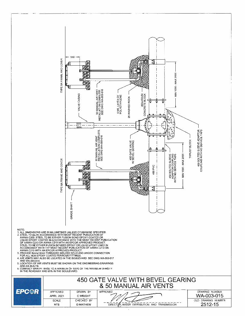
550 0:: w > 0 u 0 z < w
! u..
( < <D
w 0..
~w~ ~ (!) ~~~ u..w z o::0..~ oz ,:: in .;::a:.,: 0::W u < ...J8s: ~~ 0 u 0::
~ <z<!l '.)~ 0 ...J ~OS: w w < :!ii=O :! >- I > ::;--' en
o'.JtlJ 0 <
~ ~~en
<D 0.. s: "' en N
;1:;
. ·- - ........ --- --- -- - - -- - - ---
NOTE:
0:: w > 0 u 0
:l: w ::;
~ u.. ~ w 0.. ~
t:: < I en
....... .......
1. ALL DIMENSIONS ARE IN MILLIMETRES UNLESS OTHERWISE SPECIFIED. 2. STEEL TO BE IN ACCORDANCE WITH MOST RECENT PUBLICATION OF
AWWA C200. STEEL TO BE EITHER FUSION BOND EPOXY COATED OR LIQUID EPOXY COATED IN ACCORDANCE WITH THE MOST RECENT PUBLICATION OF AWWA C213 OR AWWA C210 WITH AN EPCOR APPROVED PRODUCT. STEEL TO BE EITHER FUSION BONDED EPOXY OR LOUID EPOXY LINED IN ACCORDANCE WITH THE MOST RECENT PUBLICATION OF AWWA C213 OR AWWA C210 WITH AN EPCOR APPROVED PRODUCT.
3. PROVIDE 6mmx12mm THREADED WELDED STUD AND ANODE CONNECTION FOR ALL NON EPOXY COATED FERROUS FITIINGS.
4. AIR VENTS MAY ALSO BE LOCATED IN THE BOULEVARD. SEE DWG WA-003-017 AND WA-003-018.
5. LOCATION OF AIR VENTS MUST BE SHOWN ON THE ENGINEERING DRAWINGS AND AS-BUILTS.
6. COMPACT GRAVEL BASE TO A MINIMUM OF 100% OF THE MAXIMUM DENSITY IN THE ROADWAY AND 95% IN THE BOULEVARD.
I 0 0
1;l
450 GATE VALVE WITH BEVEL GEARING & 50 MANUAL AIR VENTS
APPROVED
APRIL2021
DRAWN BY
CWRIGHT
o::rn oo.. !i:~ <w 0 t)
!~ >w Wen ~o rnz OI w I-!:; ;:' O(!) ID z o"'...J .,.o..
:::, 0 u
DRAWING NUMBER
WA-003-015 SCALE
NTS CHECKED BY
DMATHEW
OLD DRAWING NUMBER
DISTRIBUTION AND TRANSMISSION 2512-15

PLAN
TYPE 6A FRAME AND COVER
'o 8~
CC AND AIR VENT CAPS ~X MUST BE MINIMUM 100 ~~
AND MAXIMUM 450 ABOVE GRAVEL BASE
GRADE SHAFT _____,,,/_
CC CASING COMPLETE AS ~ PER DRAWING WA-005-005 '\
50 COMPRESSION DRAINING CURB COCK
MIN 280
50MAINSTOP
SERVICE SADDLE
MANHOLE COVER
FLUSHMOUNT HYDRANT AND OPERATING NUT TO BE AS CLOSE TO CENTERED IN MANHOLE BARREL AS POSSIBLE
65 AMA BRASS CAP
65 AMA ADAPTER TO 65 MALE THREAD
BRAZED OR SILVER SOLDERED FITIING TO 50 DIAMETER PIPE
........__ COMPACTED GRAVEL BASE MIN 150 150 HIGH AND 150 INSIDE RINGS
50 COPPER PIPE
50-90" BRAZED OR SILVER SOLDERED FITIING
450x450x50 CONCRETE BLOCK
25 WASHED ROCK
PVC WATER MAIN
NOTES: PROFILE 1. ALL DIMENSIONS ARE IN MILLIMETRES UNLESS OTHERWISE SPECIFIED. 2. COMPACT GRAVEL BASE TO A MINIMUM OF 100% OF THE MAXIMUM DENSITY IN THE
ROADWAY, AND 95% IN THE BOULEVARD. 3. BRAZED OR SILVER SOLDERED FITIINGS MAY BE REPLACED WITH EPCOR
APPROVED ALTERNATIVE. 4. MAV TO BE LOCATED ON BOULEVARD UNLESS OTHERWISE APPROVED
BY THE ENGINEER. 5. IF COVER ON COPPER PIPE IS 2.5m OR LESS, INSTALL INSULATION AS PER
WA-002-01 .
TYPICAL 50mm MANUAL AIR VENT IN ROADWAY APPROVED
APRIL2021
SCALE
NTS
DRAWN BY
CWRIGHT
CHECKED BY
DMATHEW
APPROVED DRAWING NUMBER
WA-003-016 OLD DRAWING NUMBER
TER DISTRIBUTION AND TRANSMISSION 2512-16

MIN 650 • MAX 900
ROADWAY
BOULEVARD
PLAN
MANHOLE COVER
MIN 650 • MAX 900 r /
ROADWAY
.,.,..,...---'--:=
MAINTAIN POSITIVE GRADE r 50 COPPER PIPE
/ SERVICE SADDLE
NOTES: 1. ALL DIMENSIONS ARE IN MILLIMETRES UNLESS OTHERWISE SPECIFIED. 2. COMPACT GRAVEL BASE TO A MINIMUM OF 100% OF THE MAXIMUM DENSITY IN THE
ROADWAY, AND 95% IN THE BOULEVARD. 3. FRAME AND COVER CANNOT FALL WITHIN WALK. 4. IF COVER ON COPPER PIPE IS 2.0m OR LESS, INSTALL INSULATION AS PER
DWG WA-002-001 .
~ MIN 500 -----j
~ 50 MANUAL AIR VENT INSTALLATION COMPLETE. SEE DRAWING WA-003-017
PROFILE
SEPARATE WALK OR MUL Tl-USE PA TH
TYPICAL 50mm MANUAL AIR VENT IN BOULEVARD WITH 1.5m SEPARATE WALK
APPROVED
APRIL 2021
SCALE
NTS
DRAWN BY
CWRIGHT
CHECKED BY
D MATHEW
DRAWING NUMBER
WA-003-017 OLD DRAWING NUMBER
2512-17

t--------------- MIN 2.0m- MAX 4.0m --------------l
NOTES:
ROADWAY
MANHOLE COVER
ROADWAY
/
MAINTAIN POSITIVE GRADE r 50 COPPER PIPE
/ SERVICE SADDLE
1. ALL DIMENSIONS ARE IN MILLIMETRES UNLESS OTHERWISE SPECIFIED.
MONOLITHIC WALK
BOULEVARD
PLAN
/ MONOLITHIC WALK
PROFILE
2. COMPACT GRAVEL BASE TO A MINIMUM OF 100% OF THE MAXIMUM DENSITY IN THE ROADWAY, AND 95% IN THE BOULEVARD.
3. FRAME AND COVER CANNOT FALL WITHIN WALK. 4. IF COVER ON COPPER PIPE IS 2.0m OR LESS, INSTALL INSULATION AS PER
DWG WA-002-001 .
MIN 500 - MAX 850
1 MIN 500 - MAX 850 r
MIN500 --j
~ 50 MANUAL AIR VENT / INSTALLATION COMPLETE.
SEE DRAWING WA-003-016
TYPICAL 50mm MANUAL AIR VENT IN BOULEVARD WITH 1.Sm MONOLITHIC WALK
APPROVED
APRIL2021
SCALE
NTS
DRAWN BY
CWRIGHT
CHECKED BY
D MATHEW
DRAWING NUMBER
WA-003-018 OLD DRAWING NUMBER
2512-18

REFER TO WA-003-001TO WA-003-004 FOR VALVE CASING DETAIL
EXPANSION BOARD REQUIRED ~ IF WITHIN CONCRETE SIDEWALK
(SEE NOTE 1)
FINISHED GRADE
DEPTH OF CONCRETE & GRAVEL --- -,i <!
BASE VARIES ACCORDING TO -----CITY SPECIFICATIONS. REFER
TO VOLUME 2 - ROADWAYS
250 SDR35 OR EQUIVALENT ~-..c.A PVC PIPE WITH SAND (FOR
FILLCRETE BACKFILL ONLY)
REFER TO DWG WA-004-001 FOR HYDRANT DETAIL
2 1/2" NOZZLE CAP TO BE PARALLEL TO ROAD
NOTE: 1. ASPHALT IMPREGNATED FIBRE BOARD OR ISO-STRIP-OFF. 2. VALVES AND HYDRANTS SHOULD BE DESIGNED TO FALL
OUTSIDE OF CONCRETE WALK WHERE POSSIBLE.
APPROVED BACKFILL. REFER TO DWG WA-003-008 FOR VALVE CASING IN FILLCRETE DETAIL
VALVE & HYDRANT REQUIREMENTS IN CONCRETE WALK APPROVED
APRIL2021
SCALE
NTS
DRAWN BY
CWRIGHT
CHECKED BY
DMATHEW
APP~d- z
DIRrc,~~ - D1s""~~l~BU;;;T;;::IO;;;;N:;;A;;;N:;;D;;:T;;;RA~N=SM-::1:-s=s1-::0::-N
DRAWING NUMBER
WA-003-019 OLD DRAWING NUMBER
2512-21

50 MANUAL AIR VENT VALVE \ 50 MANUAL AIR VENT VALVE SEE DWG WA-003-016 SEE DWG WA-003-016
HUB x HUB CHECK VALVE INSTALL THRUST BLOCK VALVE RUBBER DISK FACING AND \ r AS PER DWG WA-002-007 r VALVE
' ''°"'"'"'"°"G \ \ 9---~f------££----1 ( ) ~------B--$----3 L MIN 1500 _L MIN 1500- MAX 2500 _L MIN 1500 - MAX 2500 _J_ MIN 1500 _J
PLAN
MANHOLE COVER
CC AND AIR VENT CAPS MUST BE MINIMUM 100
AND MAXIMUM 450 ABOVE GRAVEL BASE I MIN 1500 --, ... ,-- MIN 1500 - MAX 2500 MIN 1500 - MAX 2500 I MIN 1500 I
FINISHED GRADE I
SEE DRAWINGS \ WA-003-006 &
WA-003-007 FOR VALVE BOX DETAIL
GRADE SHAFT
50 MANUAL AIR VENT INSTALATION COMPLETE. SEE DWG WA-003-016
DIRECT BURY ~
CHECK VALVE ""
50 MANUAL AIR VENT INSTALATION COMPLETE.
SEE DWG WA-003-016
PROFILE
NOTES: 1. ALL DIMENSIONS ARE IN MILLIMETRES UNLESS OTHERWISE SPECIFIED. 2. LOCATION OF AIR VENTS MUST BE SHOWN ON THE ENGINEERING
DRAWINGS AND AS-BUil TS. 3. COMPACT GRAVEL BASE TO A MINIMUM OF 100% OF THE MAXIMUM
DESITY IN THE ROADWAY AND 95% IN THE BOULEVARD. 4. SEE DRAWINGS WA-003-016 AND WA-003-017 FOR 50 MANUAL AIR VENT
VALVE INSTALLATION.
DIRECT BURY CHECK VALVE (300mm DIAMETER OR SMALLER)
APPROVED
APRIL2021
SCALE
NTS
DRAWN BY
CWRIGHT
CHECKED BY
D MATHEW
APPROVED
Dl~'8U~ AND ~SMISSIDN
DRAWING NUMBER
WA-003-020 DRAWING NUMBER
2512-22

wN
...a
.z
~~~~
m
mrr
n
00
!;2
··
~~
:;::
:E
:E ~
--(I)
ZZ
-Gl
GJO
:E
:E ti
1' 1
' )>
o
o;o
~~m
66
z
!:38
~ )>
)>
"'
Tl-
nr
Oo
r
cnl
"O ~
::O;o
!i:
z (")
~
JJ
Or,~
-i
)>
0 ~
~::
o
en
r I'\
,)<
m
o
m
n:i::
m
~
0 ::o
o<n
~cc
mo
~
-i -o
m
I ;c
(I)
::oo<
n C
-iQ
0
~
(")
0 <
nm
-i
-i
() :i
:: :;:
: m
i I
"Tl
a,:
:!m
)>
("
) ro
;c
-i
:,<
OZ
:!:
::cm
Gi
z
::0
~fllc
ii m
o
::c
Ill
::o
om
::E
~
-i
-<
m
mc<
n
o--
o
c;c
m
:c
;ii~
~
mm
-
-< :;
::zm
m
-1!=
' 0
Z<
n
-i
.
o!
;;i/
~ ~
z :E
l~
--f
~1
1 -u
S:)
1 o
l r
en I
)>
:i'J I
()
ffi1
§1
m
~
I s::
> I
m
zl
o,
z -i
I
~I
--f
en I
-~
I --f
~
I
-< ~
I I -u
()
)>
r 0
I -
r ~~
0
"'
0 )>
~
cn I
I -
oz
--" -
OC
il w
z
I C
i) ~
z
Oz
I C
--" C
0
~
:;:: o
m
Ill
--" J
J m
JJ
15
0µ
(6
MIL
) L
AY
ER
O
F P
OL
YE
TH
YL
EN
E
2 1
/2"
NO
ZZ
LE
CA
P T
O
BE
PA
RA
LL
EL
TO
RO
AD
CO
NC
RE
TE
TO
BE
50
BE
LO
W
FL
AN
GE
NU
TS
ON
HY
DR
AN
T V
AL
VE
75
X 3
00 X
60
0
TR
EA
TE
D R
OU
GH
FIR
H
YD
RA
NT
SE
AT
gJ
a----
-M
IN 9
00 ---
--J
r 4
1/2
" P
UM
PE
R C
AP
T
O F
AC
E S
TR
EE
T
FIN
ISH
ED
GR
AD
E
TY
PE
B S
CR
EW
TY
PE
\
CA
SIN
G A
S P
ER
D
WG
WA
-00
3-0
01
AL
L D
RA
IN H
OL
ES
T
O B
E U
NO
BS
TR
UC
TE
D
AN
D F
RE
E T
O D
RA
IN
, ... ,,
' ..
' ..
' ..
RO
AD
WA
Y
SE
E D
RA
WIN
GS
WA
-00
3-0
06
&
WA
-00
3-0
07
FO
R V
AL
VE
BO
X D
ET
AIL
50 X
10
0 T
RE
AT
ED
BL
OC
KIN
G
SU
PP
OR
TS
VA
LV
E I
ND
EP
EN
DA
NT
LY
O
F P
IPE
UN
TIL
CO
NC
RE
TE
IS
SE
T
CO
NC
RE
TE
TH
RU
ST
BL
OC
K T
O
BE
EM
BE
DD
ED
IN
TR
EN
CH
WA
LL
50
X 1
00 T
RE
AT
ED
BL
OC
KIN
G
SU
PP
OR
TS
VA
LV
E I
ND
EP
EN
DA
NT
LY
O
F P
IPE
UN
TIL
CO
NC
RE
TE
IS S
ET
CO
NC
RE
TE
T
HR
US
T B
LO
CK

)>
)>
z ~1 ~
:g
~)>
r=
:rJ
en
r "'
O
m
o <
~
f!l1
0 m
m
0 2
()
0 '"O
S::
m
~
I )>
("
) CD
~
;,;
::cm
i5
z
C
m
o :E
~
::c
(lJ
~
-<
::a -<
)>
"Tl
" " -
:rJ
::a
0 <
m
m
0
:c -< 0 ~ z ~
'"O
r }>
()
m
s:: m
z ~ - ~
0 -<
5 ~
o
'"O
r,.,
o )>
~
()
01
~
I ;j;
...i
..:::;;
o
z
}>
wz
OG
l I
Gl
.Jl.
z r
Oz
I c -
We a
s:
s:: 0
~
~
"':
rJ
:rJ
~~
!'l~
C
llC/l
C/l
C l>
rnr
n~~F
cc::
,o!2
~
~o
-,,;
::
:::;;:::;;
rn~~
zzzq
i 5
G)G
);1r
oz
:::;,:
::;,
CC
/l
tt ~
~ o
o
~m
6"'
7'
-<
-0
Cl
Z
!:31:l
~~
00
~E
;u
;u
Cl)
;::
on
s:
!!j
~~ ~~
n:
:r:
~C
l)
fll8
Ille
irlc
'i ~~
:i!
:ll ill
rn ;u
O
j,C
ll
c~
"1
10
cnm
'"
0-i
~
o
;u::r
: a,
:::l
om
rO
<
;u
oz
m:::;
; n
;u
cu
; A
m
com
;u
O
-<C
ll m
e
m-u
O
;ii
"11m
~~
8~
mm
;u
-;:
:z
:::;; e
l ~0
~-
0 gJ
2 1/
2" N
OU
LE
CA
P T
O
BE
PA
RA
LL
EL
TO
RO
AD
150µ
(6
MIL
) L
AY
ER
O
F P
OL
YE
TH
YL
EN
E
OR
GE
OF
AB
RIC
IN-L
INE
CH
AM
BE
R T
O B
E
LO
CA
TE
D A
T S
TA
ND
AR
D D
.O.B
.
MIN
IMU
M O
F 0
.3 C
UB
IC M
ET
ER
S
300
DE
EP
OF
25
WA
SH
ED
RO
CK
ALL
DR
AIN
HO
LE
S
TO
BE
UN
OB
ST
RU
CT
ED
A
ND
FR
EE
TO
DR
AIN
150µ
(6
MIL
) L
AY
ER
O
F G
EO
FA
BR
IC
CO
NC
RE
TE
T
HR
US
T B
LO
CK
CO
NC
RE
TE
TO
BE
50
BE
LO
W
FL
AN
GE
NU
TS
ON
HY
DR
AN
T V
AL
VE
75 X
30
0X
60
0
TR
EA
TE
D R
OU
GH
FIR
H
YD
RA
NT
SE
AT
g:
t-----
MIN
900
-----i
r 4
112"
PU
MP
ER
CA
P
TO
FA
CE
ST
RE
ET
FIN
ISH
ED
Et?
~
z
Nci
: 8f!
e E
~
Illa
c,
;1-
I.,,
._;
...
&
•\
I.,.
~ TY
PE
B S
CR
EW
T
YP
E C
AS
ING
AS
P
ER
DW
G W
A-0
03
-001
RO
AD
WA
Y
VA
LV
E S
TE
M R
ISE
R A
S R
EQ
UIR
ED
. S
EE
AP
PR
OV
ED
PR
OD
UC
TS
LIS
T
CO
MP
AC
TE
D C
LAY
V S
EE
DR
AW
ING
S W
A-0
03
-00
6
& W
A-0
03
-00
7 F
OR
VA
LV
E
BO
X D
ET
AIL
r M
INIM
UM
300
SA
ND
CO
VE
R
50 X
100
TR
EA
TE
D B
LO
CK
ING
S
UP
PO
RT
S V
AL
VE
IN
DE
PE
ND
EN
TLY
O
F P
IPE
UN
TIL
CO
NC
RE
TE
IS
SE
T
CO
NC
RE
TE
TH
RU
ST
BL
OC
K T
O
BE
EM
BE
DD
ED
IN
TR
EN
CH
WA
LL
50
X 1
00 T
RE
AT
ED
BL
OC
KIN
G
SU
PP
OR
TS
VA
LV
E I
ND
EP
EN
DE
NT
LY
O
F P
IPE
UN
TIL
CO
NC
RE
TE
IS
SE
T
CO
NC
RE
TE
T
HR
US
T B
LO
CK
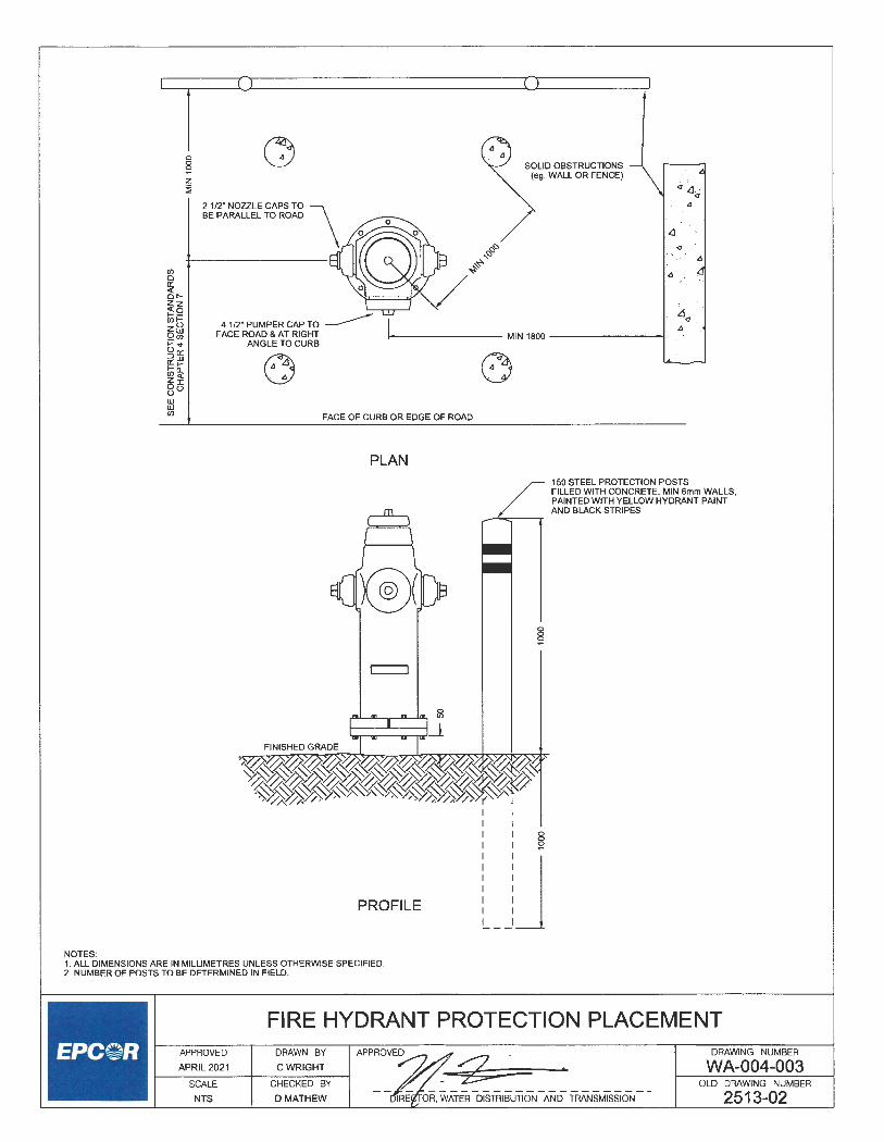
NOTES:
~--___._C.,....i ____________ ___.,_[.,....> ____ ~
0 0
~ z ~
2 1/2" NOZZLE CAPS TO \ BE PARALLEL TO ROAD \
SOLID OBSTRUCTIONS (eg. WALL OR FENCE)
~ .·
<J
,<I
,<I
4 1/2" PUMPER CAP TO ------FACE ROAD & AT RIGHT i--------- MIN 1800 --------t
ANGLE TO CURB
FACE OF CURB OR EDGE OF ROAD
PLAN
PROFILE
/
150 STEEL PROTECTION POSTS FILLED WITH CONCRETE. MIN 6mm WALLS, PAINTED WITH YELLOW HYDRANT PAINT AND BLACK STRIPES
§
1. ALL DIMENSIONS ARE IN MILLIMETRES UNLESS OTHERWISE SPECIFIED. 2. NUMBER OF POSTS TO BE DETERMINED IN FIELD.
FIRE HYDRANT PROTECTION PLACEMENT APPROVED
APRIL 2021
SCALE
NTS
DRAWN BY
CWRIGHT
CHECKED BY
DMATHEW
- -~ '
OR, WATER DISTRIBUTION AND TRANSMISSION
DRAWING NUMBER
WA-004-003 OLD DRAWING NUMBER
2513-02

Cf--~· --- -~ --- ------
/
, HYDRANT CONTROL I VALVE (SEE NOTE 5)
' ' I I
Cf Cf
EXISTING FIRE HYDRANT IN CONTROL VALVE ACTIVE CONSTRUCTION ZONE BESIDE HYDRANT
"-._ ORANGE SAFETY BARRIER FENCE
I
~--~------- ~ j @~ """'"' ,o,,,o,
EXISTING FIRE HYDRANT IN 'O' VALVE (SEE NOTE 5) ACTIVE CONSTRUCTION ZONE
~ ORANGESAFETY BARRIER FENCE
i-----1500MIN ---
HYDRANT CONTROL ' VALVE (SEE NOTE 5)
Cf----*---- --- -
~--~---
"''""" "" """""'" / ~ CONTROL VALVE IN FRONT OF HYDRANT
NOTES: 1. ALL DIMENSIONS ARE IN MILLIMETRES UNLESS OTHERWISE SPECIFIED. 2. EXISTING HYDRANTS TO HAVE ORANGE SAFETY BARRIER FENCE ERECTED
1.5m EITHER SIDE OF HYDRANT. THE ROAD FACING SIDE MUST REMAIN CLEAR OF FENCING AND NO MATERIAL STOCK PILES, EQUIPMENT, ETC. ARE TO BLOCK ACCESS TO HYDRANT.
3. DO NOT BLOCK STEAMER NOZZLE. 4. ORANGE SAFETY BARRIER TO BE SECURED BY STEEL T-POSTS. 5. IF HYDRANT CONTROL VALVE IS BESIDE OR BEHIND THE HYDRANT, EXTEND
FENCING TO 1.5m OUTSIDE OF VALVE. 6. CONTACT EPCOR WATER SERVICES INC. AT 780-412-4500 A MINIMUM OF
72 HRS PRIOR TO THE START OF CONSTRUCTION TO INSTALL WHITE DISK ON HYDRANT AND WITHIN 72 HRS OF REMOVAL OF HOARDING TO REMOVE WHITE DISK.
ACTIVE CONSTRUCTION ZONE
CONTROL VALVE BEHIND HYDRANT
FIRE HYDRANT HOARDING DETAIL
z :! 0 0
"'
,___:_:_:_~_~_:_i2_~ _ __, __ ~_RA_w_:_~G_:_;_--, APPROVED~- • . 2s ' DRAWING NUMBER
WA-004-004 SCALE CHECKED BY , OLD DRAWING NUMBER
NTS D MATHEW DIREC R, WATER DISTRIBUTION AND TRANSMISSION

.iY /
PROPOSED FACE OF CURB OR EDGE OF ASPHALT
MIN 1500
... I
<
MIN 1500
C/L DITCH - - - - _')+--------------------+C- - - - -::J CULVERT AS REQUIRED C::
PLAN FIRE HYDRANT ~
PROTECTION ""
MAX 1.0%-2.0%
ROAD CRUSH/ BASE GRAVEL/ASPHALT ~
_-=,__ __ __J_.:......_::...c.:==~-+-~-___:
NOTES:
0 CULVERT AT C/L DITCH
AS REQUIRED
SODDED SLOPE \
4
1. ALL DIMENSIONS ARE IN MILLIMETRES UNLESS OTHERWISE SPECIFIED. 2. PAD TO BE 50mm ROAD CRUSH, BASE GRAVEL OR ASPHALT COMPACTED
TO 100% OF STANDARD PROCTOR DENSITY CIW CULVERT AS REQUIRED 3. FOR HYDRANT PLACEMENT, REFER TO DRAWING WA-004-001 . 4. FOR HYDRANT PROTECTION PLACEMENT REFER TO DRAWING WA--004-002. 5. SEE DRAWING WA-007-003 FOR CATHODIC PROTECTION REQUIREMENTS.
ACCESS PAD
\__ EXISTING GROUND
SECTION A-A
6. MINIMUM 1.5m TO THE EDGE OF PAD IS REQUIRED FOR ALL APPURTENANCES. 7. FOR CULVERT CONSTRUCTION, REFER TO DRAWING N0.3020 OF THE CITY
OF EDMONTON DESIGN AND CONSTRUCTION STANDARD VOL. 2 8. ALL SIDE SLOPES TO BE MINIMUM 4H:1V.
APPROVED
APRIL2021
SCALE
NTS
DRAWN BY
CWRIGHT
CHECKED BY
DMATHEW
FIRE HYDRANT ACCESS PAD APPROVED . •
~""'~ OSrn'8lJ-'QN ANO rnANs.,ss,oN
DRAWING NUMBER
WA-004-005 OLD DRAWING NUMBER

INSULATION PER DWG WA-002-001
50 X 100 X 750 SERVICE MARKER WITH \ 450 ABOVE GROUND PAINTED RED \
CAP_/
CASING\
TAPPED MAINSTOPS ARE TO BE STAGGERED FROM \ CROWN TO 30" OF PIPE WITH 1-3 THREADS SHOWING. WHERE TAPPED INTO TEFLON PIPE, TEFLON TAPE TO BE USED ON THREADS OF MAINSTOP. 40 AND 50 TAPS REQUIRE THE USE OF A SERVICE SADDLE. PIPE GREATER THAN 300 REQUIRES THE USE OF A SERVICE SADDLE
~ 300 MIN SAND COVER ~ 300 DIAMETER GOOSENECK
LOOSELY FILLED SAND BAGS (NO CEMENT)
1000
I I I I I I
5.5 kg (121b) ZINC ANODE FOR COPPER SERVICE (SEE DWG WA-007-006)
NOTES:
TUNNEL SEWER SERVIC PIPES UNDER WATER MAIN TO MAINTAIN WATER MAIN SUPPORT ( OR SAND BAG BRIDGE). ENSURE NO JOINTS WITHIN 1.5 m OF CROSSING
1. ALL DIMESIONS ARE IN MILLIMETRES UNLESS OTHERWISE SPECIFIED. 2. AN ADDITIONAL GOOSENECK IS REQUIRED AT EACH SEWER CROSSING. 3. MAINSTOP TAPS SHALL BE A MINIMUM OF 600mm APART AND NO LESS THAN 600mm
FROM A COUPLING OR COLLAR. 4. COPPER SERVICE PIPE SHALL BE ONE OF THE CONTINUOUS PIECE. SHOULD LENGTH
EXCEED 20m, A DOUBLE UNION WILL ALLOWED AND SIZE OF COPPER MUST BE 25mm MINIMUM.
5. INVERT ELEVATION OF WATER SERVICE PIPES AT PROPERTY LINE SHALL BE 2.59m BELOW ESTABLISHED GRADE.
6. WHERE ENGINEER APPROVED COVER OVER WATER SERVICE TO BE LESS THAN 2.59m, SERVICE IS TO BE INSULATED IN ACCORDANCE WITH DWG WA-002-001 .
7. ZINC ANODE SHALL BE ATTACHED TO COPPER PIPE 1.0m FROM CC WITH AN ALL BRONZE (INCLUDING NUTS AND BOLTS) CLAMP OR APPROVED EQUIVALENT.
8. ZINC ANODE TO BE EMBEDDED INTO TRENCH WALL TO PROVIDE FOR MIN. 50mm OF NATIVE CLAY SURROUNDING ANODE.
9. REQUIRES ENGINEER'S APPROVAL PRIOR TO INSTALLATION. 10. INSULATION MUST BE INSTALLED ABOVE ALL VERTICAL GOOSENECK$ PER DWG WA-002-001 .
w z ::J
~ w Q.
~ Q.
I
I ' -'
/
MARKERATP/L PAINTED GREEN IF SEWER ONLY
' EPOXY COATED CAST IRON BOOT
I
SERVICES MAY BE EXTENDED r INTO PRIVATE PROPERTY (SEE DWG WA-005-007 FOR DETAILS)
PLUG
CAST IRON CHAIR TO FIT MANUFACTURER'S CURB STOP AND LAG BOLTED TO THE THREADED BLOCK
50mm AND SMALLER COPPER WATER SERVICE APPROVED
APRIL2021
SCALE
NTS
DRAWN BY APPROVED
C WRIGHT -- ··- ·",c _
CHECKED BY
D MATHEW DIRECTOR, WATER DISTRIBUTION AND TRANSMISSION
DRAWING NUMBER
WA-005-001 OLD DRAWING NUMBER
2514-01

0 0 M
0 0 M
0 0 <D z ~
L PLAN VIEW
PVC PIPE:
HORIZONTAL GOOSENECK FOR COPPER OR COMPOSITE SERVICE TUBING
SANITARY SEWER SERVICE
WATER SERVICE
MAINSTOPS TO BE STAGGERED FROM SPRING LINE TO 15 DEGREES OF PIPE WITH 1-3 THREADS SHOWING. TEFLON TAPE TO BE USED ON THREADS OF MAINSTOP. TAPS ON PIPE GREATER THAN 300 DIAMETER REQUIRE A SERVICE SADDLE. SUPPORT SERVICE TUBING ON LEDGE FORMED IN TRENCH WALL OR ON LOOSELY FILLED SAND BAGS.
MIN 300 SAND COVER
TUNNEL SEWER SERVICE PIPES UNDER WATER MAIN TO MAINTAIN
WATER MAIN SUPPORT (OR SAND BAG BRIDGE). ENSURE NO JOINTS WITHIN
1.5m OF CROSSING.
NOTES:
1.5m MIN CL WM TO SEWER JOINT
1. ALL DIMENSIONS ARE IN MILLIMETRES UNLESS OTHERWISE SPECIFIED. 2. AN ADDITIONAL GOOSENECK IS REQUIRED AT EACH SEWER CROSSING. 3. MAINSTOP TAPS SHALL BE A MINIMUM OF 600mm APART, AND NO LESS THAN 600mm
FROM A COUPLING OR COLLAR. 4. COMPOSITE SERVICE TUBING SHALL BE SUPPORTED EVENLY ALONG ITS ENTIRE
LENGTH WITH NO FREE SPANS. 5. INVERT ELEVATION OF WATER SERVICE PIPES AT PROPERTY LINE SHALL BE 2.70m +/-0.15m
BELOW ESTABLISHED FINISHED GRADE. 6. WHERE ENGINEER APPROVED COVER OVER WATER SERVICE TO BE LESS THAN 2.00m
SERVICE IS TO BE INS ULA TED IN ACCORDANCE WITH DWG WA-002-001 . 7. FOR CURB COCK AND CURB BOX ASSEMBLY SEE DWG WA-005-003 TO WA-005-006. 8. ZINC ANODE FOR COPPER SERVICES TO BE EMBEDDED IN TRENCH WALL TO
PROVIDE FOR MIN. 50mm OF NATIVE CLAY SURROUNDING ANODE AS PER DWG WA-007-006.
LOOSELY FILLED SANDBAGS (NO CEMENT)
50mm AND SMALLER COPPER, POLYMER, OR COMPOSITE WATER SERVICE
APPROVED DRAWN BY APPROVED ?/; APRIL 2021 C WRIGHT :<L -
1----SC_A_L_E ____ C_H_E_C_K_E_D_B_Y--1 ~
NTS D MATHEW DIRECTOR, ATER DISTRIBUTION AND TRANSMISSION
DRAWING NUMBER
WA-005-002 OLD DRAWING NUMBER
2514-02

t-- 41 --Ir BRASS PLUG WITH 1._1 1 I 5 THREADS STANDARD
~) I: I ,· '"""'°' C" =1 g
11-,-1F1 SEC~~~ ---s, : IS
r- ~48___..j
SLOT 18LONG 8 WIDE, 10 DEEP •
"1" DENOTES SERVICES ~ 25 AND SMALLER "'
DETAIL "A" FINISHED GRADE ;;;
o mt STANDARD "' IP THREADS i 0 ~ _ / 100 PVC SEWER PIPE
NOTES:
/ DR-35 1.0 m LONG
OPERATING ROD EXTENDS MINIMUM 50 ABOVE LOWER CASING
/
TOPTUBE 32 (1 1/4") GALVANIZED SCHEDULE 40 PIPE MIN 1.6m (5'3") LONG
/
BEGINNING OF PIGTAIL TO BE A MINIMUM OF 200 FROM TOP OF ROD
1525 X 12.7 STAINLESS STEEL OPERATING ROD FASTENED WITH STAINLESS STEEL OR BRASS COTIER PIN TO CURB STOP
-:---.....__ BOTIOM TUBE 25 (1") GALVANIZED SCHEDULE 40 PIPE 1.3m (4'3") LONG
~ TROJAN ESB1 OR SIMILAR ,,.-- CC BASE CASTING EPOXY
COATED
CC CHAIR TO SUIT CURB COCK AND SERVICE BOX BOOT
~,...,f~J:;::;l:::;:::;:::;-- FASTEN WITH 2 -10 X 50
50 X 150 X 300 TREATED WOOD BLOCKS
LONG LAG BOLTS
1. ALL DIMENSIONS ARE IN MILLIMETRES UNLESS OTHERWISE SPECIFIED.
2. OPERATING ROD SHALL BE SUPPLIED AS A SINGLE UNIT COMPRISED OF A SOLID STAINLESS STEEL ROID, ATIACHED TO A CLEVIS WITH A STAINLESS STEEL RIVET.
3. THE MANUFACTURERS NAME SHALL BE EMBOSSED ONTO THE CLEVIS.
25 STANDARD \
IP THREADS \~I RAISED • LETIERING
BRASS CAP
COTIERPIN
NOMINAL DIAMETER A DIAMETER
MAX. I MIN. 6.35mm 5.7mml5.6mm
SEE DETAIL "A"
11mmX11mm CORED HOLE
f+o4l L--0.QJ
Goal L.:.o-Oi.l
OUTSIDE EYE HOLE SIZE LENGTH DIAMETER BMINIMUM RECOMMENDED L
12.7mm 6.7mm 55mm
STAINLESS STEEL OR 11mm X 11mm ROD BRASS COTTER PIN
! ,,,- BEGINNING OF PIGTAIL SECTION A-A , / TO BE A MINIMUM OF \ 200 FROM TOP OF ROD
BOTIOM 25mm OF ROD TO BE FORGED
SQUARE 11mm X 11mm (COLD FORGED)
SEE DETAIL "B"
3.5 STAINLESS STEEL RIVET
· _,,,,- MANGANESE BRONZE OR / STAINLESS STEEL CLEVIS
STAINLESS STEEL OR BRASS COTTER PIN
DETAIL "B"
7mm HOLE
SERVICE BOX DETAIL FOR 20mm, 25mm WATER SERVICE (TWO PIECE CASING)
APPROVED
APRIL2021
DRAWN BY
CWRIGHT
APPROVED DRAWING NUMBER
SCALE
NTS
CHECKED BY
DMATHEW
WA-005-003 OLD DRAWING NUMBER
2514-03a

I I I 5 THREADS STANDARD PIPE STOPPERS (3)
f-- 34 --tr BRASS PLUG WITH
: 'i' :· IPTHREADS 1 86
1_ I I ~ . r, 9-,-1P I SEC~,~~ -- ~:::::::::e1=::::=:::i:::s::;. L() L()
DETAIL "A" BOOT BOTIOM VIEW
FINISHED GRADE ;;;
fil ]Tif STANDARD IP THREADS
i g "' / 100 PVC SEWER PIPE
/ DR-35 1.0 m LONG
NOMINAL DIAMETER A DIAMETER
MAX. I MIN.
SLOT18LONG 8 WIDE, 10 DEEP
25STANDARD \ r5±fj IPTHREADS \~7
RAISED • LETIERING
BRASS CAP
COTIERPIN
OUTSIDE EYE HOLE SIZE LENGTH DIAMETER BMINIMUM RECOMMENDED L
6.35mm 5.7mml5.6mm 12.7mm 6.7mm 55mm
NOTES:
/
BEGINNING OF PIGTAIL TO BE A MINIMUM OF 200 FROM TOP OF ROD
1525 X 12.7 STAINLESS STEEL OPERATING ROD FASTENED WITH STAINLESS STEEL OR BRASS COTIER PIN TO CURB STOP
-------- MIN 2150 X 25 (1 ") GALVANIZED SCHEDULE 40 PIPE
TROJAN N-ESB1 OR SIMILAR CC BASE CASTING BLACK ASPHALT VARNISH
CC CHAIR TO SUIT CURB COCK AND SERVICE BOX BOOT
J....__J:~j;::;t::::;f:::;-- FASTEN WITH
SOX 150X300 TREATED WOOD BLOCKS
2 - 10mm X 50mm LONG LAG BOLTS
1. ALL DIMENSIONS ARE IN MILLIMETRES UNLESS OTHERWISE SPECIFIED.
2. OPERATING ROD SHALL BE SUPPLIED AS A SINGLE UNIT COMPRISED OF A SOLID STAINLESS STEEL ROID, ATIACHED TO A CLEVIS WITH A STAINLESS STEEL RIVET.
3. THE MANUFACTURERS NAME SHALL BE EMBOSSED ONTO THE CLEVIS.
I '
SEE DETAIL "A"
11mmX11mm CORED HOLE
[+o.4] L-0.QJ
[+o.o] L:.<>.Di.J
11mmX11mmROD
! ~ BEGINNING OF PIGTAIL , / TO BE A MINIMUM OF \ 200 FROM TOP OF ROD
BOTIOM 25mm OF ROD TO BE FORGED
SQUARE 11mmX 11mm (COLD FORGED)
SEE DETAIL "B"
3.5mm STAINLESS STEEL RIVET
· .,,,,,..- MANGANESE BRONZE OR / STAINLESS STEEL CLEVIS
STAINLESS STEEL OR BRASS COTIER PIN
IX) M
SECTION A-A
STAINLESS STEEL OR BRASS COTIER PIN
7mmHOLE
~38--l
DETAIL "B"
SERVICE BOX DETAIL FOR 20mm, 25mm WATER SERVICE (ONE PIECE CASING)
l--_:_:_:_~L_o2_v~-~-1---+---~-RA_w_:_~G_H_\_v_---l APPROVED~ ·:-2 - , SCALE CHECKED BY _i;e:::._ NTS D MATHEW DIR ATER DISTRIBUTION AND TRANSMISSION
DRAWING NUMBER
WA-005-004 OLD DRAWING NUMBER
2514-03b

SEE\ DETAIL "A" \
18
"1 18 I
c102=1 sEc¥i~~ ----_ SI l I§
STANDARD "2" DENOTES SERVICES I-- 48 __j IP THREADS 40 AND LARGER
RAISED LETIERING
BRASS CAP FINISHED GRADE Ja
.... N
~ t--- 55 ----j
STAINLESS STEEL OR BRASS COTIER PIN
0
~
"i 0 0
"'
-~ c--- c- STANDA RD
EADS IPTHR
100 PVC SEWER PIPE DR-35 1.0 m LONG r ~ 18 x 18 x 50 SQUARED END
/ FORMED ON 22 DIA ROD
OPERATING ROD EXTENDS MINIMUM 50 ABOVE LOWER CASING
NOTES:
:is
L ~ 22 DIA MILD STEEL
/ ROD(7/8")
I
-itir I.:: 788 :j
DETAIL "A"
HOLE PLACEMENT 7mm DIA. HOLE DRILLED 6mm TO CENTER FROM BOTIOM OF CLEVIS STAINLESS STEEL OR BRASS COTIER PIN
1. ALL DIMENSIONS ARE IN MILLIMETRES UNLESS OTHERWISE SPECIFIED. 2. OPERATING ROD SHALL BE SUPPLIED AS A SINGLE UNIT
COMPRISED OF A SOLID STAINLESS STEEL ROID, ATIACHED TO A CLEVIS WITH A STAINLESS STEEL RIVET.
3. THE MANUFACTURERS NAME SHALL BE EMBOSSED ONTO THE CLEVIS.
4. CLEVIS FORMED FROM MILD STEEL FLAT 120mm x 50mm x 9mm (4 3/1" X 2" X 3/8")
7mm HOLE
TOP TUBE 32mm (11/4") GALVANIZED SCHEDULE 40 PIPE MIN 1.6m (5'3") LONG
1525 X 12.7 STAINLESS STEEL OPERATING ROD FASTENED WITH STAINLESS STEEL OR BRASS COTIER PIN TO CURB STOP
=---- BOTIOM TUBE 25 (1") GALVANIZED SCHEDULE 40 PIPE 1.3m (4'3") LONG
'- TROJAN ESB2 OR SIMILAR CC BASE CASTING EPOXY COATED
CC CHAIR TO SUIT CURB COCK AND SERVICE BOX BOOT
.....,.,_,..~~~~~~:;::; FASTEN WITH 2-10X50
50mm X 150mm X 300mm TREATED WOOD BLOCKS
LONG LAG BOLTS
SERVICE BOX DETAIL FOR 40mm, 50mm WATER SERVICE (TWO PIECE CASING)
APPROVED
APRIL2021
DRAWN BY
CWRIGH:r
APPROVED DRAWING NUMBER
SCALE
NTS
CHECKED BY
D MATHEW
~ ~ DIRE OR, wATERD1srn1:10N AND TRANSMISSION
WA-005-005 OLD DRAWING NUMBER
2514-04a

NOTES:
i.a; FINISHED GRADE
STANDARD IP THREADS SEE DETAIL "A"
/ 100 PVC SEWER PIPE / DR-35 1.0 m LDNG
......_____ MIN 2150 X 32 (1 1/4') GALVANIZED SCHEDULE 40 PIPE
TROJAN N-ESB2 OR SIMILAR CC BASE CASTING BLACK ASPHALT VARNISH
CC CHAIR TO SUIT CURB COCK AND SERVICE BOX BOOT
.,!_.....,J:;!~:;!:~t:;--- FASTEN WITH
50X150X300 TREATED WOOD BLOCKS
2-10X50 LONG LAG BOLTS
1. ALL DIMENSIONS ARE IN MILLIMETRES UNLESS OTHERWISE SPECIFIED. 2. OPERATING ROD SHALL BE SUPPLIED AS A SINGLE UNIT
COMPRISED OF A SOLID MILD STEEL ROD WITH A MILD STEEL CLEVIS WELDED TO IT.
3. THE MANUFACTURERS NAME SHALL BE EMBOSSED ONTO THE CLEVIS.
4 . CLEVIS FORMED FROM MILD STEEL FLAT 120mm x 50mm x 9mm (4 3/4" X 2" X 3/8")
t-- 48 --ir BRASS PLUG WITH I I I 25 STANDARD
'I I : I : IP THREADS
'
SLOT18LONG ~ 8 WIDE, 10 DEEP ~
STANDARD ----......~I IP THREADS "-
' RAISED LEITERING
BRASS CAP
-i 18 r
r / 18 x 16 x 50 SQUARED END / FORMED ON 22 DIA ROD
~
l r 22 DIA MILD STEEL / ROD(7/8')
I
I
~
I ... [ ..
;:I; 7mm L ' H_o_L_E-+--'-""
l--50_.jf
DETAIL "A"
HOLE PLACEMENT 7mm DIA. HOLE DRILLED 6mm TO CENTER FROM BOITOM OF CLEVIS
STAINLESS STEEL OR BRASS GOITER PIN
STAINLESS STEEL OR BRASS GOITER PIN
PIPE STOPPERS (3)
BOOT BOITOM VIEW
SERVICE BOX DETAIL FOR 40mm, 50mm WATER SERVICE (ONE PIECE CASING)
DRAWING NUMBER
WA-005-006 ,___:_:_:_~L_o2_v~_i_, ____ ~_:_:_~G_H_B~----t APPROVED . • :2 -SCALE CHECKED BY __ :7:lfC _________________ _ NTS D MATHEW DIRECTOR, WATER DISTRIBUTION AND TRANSMISSION
OLD DRAWING NUMBER
2514-04b

TYPICAL DOUBLE SERVICE PLAN VIEW
OFFSET APPROX. 1.35m
w z ::::;
SERVICE EXTENSIONS MUST NOT CROSS PROPERTY LINE AT ANY TIME
/;
100PLUG (PAINTED GREEN)
,r- 150 x 100 REDUCER / {PAINTED RED)
[ _____ _ URW BOUNDARY
g
WATER SERVICE
SANITARY SEWER SERVICE
STORM SEWER SERVICE --(WHERE APPLICABLE)
{WHERE APPLICABLE)
WATER MAIN
SANITARY SEWER SERVICE
----- STORM SEWER SERVICE
/
INSTALL JOINT FOR SEWER SERVICES AT PROPERTY LINE
PROPERTY LINE -------------- -- ---- -- -- ---
22.5° BENDS
l _ __ ___ PROPERTY LINE
WATER SERVICE __/
SERVICE TO ENTER IN THE MIDDLE OF THE PROPERTY AND TO INTERSECT THE P/L AT 90'
150x 100REDUCER _/ (PAINTED RED)
APPROVED
APRIL2021
SCALE
NTS
URW BOUNDARY -------------
TYPICAL SINGLE SERVICE PLAN VIEW
\_ 100PLUG (PAINTED GREEN)
NOTES: 1. ALL DIMENSIONS ARE IN MILLIMETRES UNLESS OTHERWISE SPECIFIED. 2. WATER AND SEWER SERVICES MAY BE EXTENDED BEYOND GAS URW. 3. EPCOR AND THE CITY EXCEPT NO RESPONSIBILITY FOR THE CONSTRUCTION
OR SERVICES INSTALLED ON PRIVATE PROPERTY. 4. MARK ENDS OF SERVICES WITH A 50mm x 100mm x 750mm STAKE PROTRUDING
450mm ABOVE GROUND AND PAINTED BLUE. MARK THE CURB CONTROL VALVE WITH A SIMILAR STAKE PAINTED RED.
5. PERMEABLE FILTER CLOTH MUST BE USED ON THE END OF SERVICES TO PREVENT INTRUSION OF DEBRIS AND TO ALLOW FLOW TESTING OF CURB STOP
6. REFER TO APPLICABLE SECTIONS OF THESE STANDARDS FOR REQUIREMENTS FOR SEWERS AND SEWER SERVICES.
7. SANITARY AND STORM SERVICES MUST HAVE A BELL AT PROPERTY LINE. 8. ENSURE NO JOINT WITHIN 1.5m OF CROSSING LOCATION.
TYPICAL SINGLE AND DUAL SERVICE FOR NEW DEVELOPMENT
DRAWN BY
CWRIGHT
CHECKED BY
DMATHEW
APPROVED -"Jt-::-,A?--g__ DIRE~ ,D=N AND TRANSMISSION
DRAWING NUMBER
WA-005-007 OLD DRAWING NUMBER
2514-09

P/L I
MIN 300 + r MIN300
- -- LJ -- -- - -- -- -- -_J_ PROPERTY LINE (P/L)
g
300 300 300 300
~ w
w __, w a, (.)
~ (.) <( 5 5 (.)
(.) a:: ::; a:: w ::; w a_ Cl) a_ Cl) a_
a_ a:: <( a:: <( w w !!: f-!!: f- <( <( w ::: w w ::: w
(.) (.) (.) (.)
~ 5 5 5 a:: a:: a:: w w w w Cl) Cl) Cl) Cl)
a:: a:: a:: a:: w w w w ::: ::: ::: ::: w w w w Cl) Cl) Cl) Cl)
:;; >- :;; >-a:: a:: ! a:: ~ 0 0 f-
f- z en z en <( ;;i en
SANITARY SEWER MAIN
WATER MAIN
I----- MIN 600 -----,i-------- MIN 600 ----------<.+--- MIN 600 __J
NOTES: 1. ALL DIMENSIONS ARE IN MILLIMETRES UNLESS OTHERWISE SPECIFIED. 2. SERVICES MAY BE EXTENDED INTO PRIVATE PROPERTY BEYOND GAS
EASEMENT (SEE DWG WA-005-007 FOR DETAILS). 3. SANITARY AND STORM SERVICES MUST HAVE A BELL AT PROPERTY LINE. 4. REFER TO APPLICABLE SECTIONS FOR REQUIREMENTS FOR SEWER MAINS
AND SEWER SERVICES.
PLAN VIEW
TYPICAL DUAL SERVICE FOR DUPLEX/ SEMI-DETACHED LOTS
APPROVED
APRIL 2021
SCALE
NTS
DRAWN BY
CWRIGHT
CHECKED BY
DMATHEW
APPROVED
.. ·?/// :z -~iciF(WATER DISTRIBUTION AND TRANSMISSION
DRAWING NUMBER
WA-005-008 OLD DRAWING NUMBER
2514-07

I>
~~ wz 5o Z...J
8g Co Ww Ual a: a: 0::::> >->- LI. I- O:') a::::;; z en
=>::::> iii i5 t-u C!J al:::;; a: z ~ti: z ~~
w=> ~o :::; Uz
0. I::;, 52. Oen ::::> ~g 0. C!J
al a: 0 r- fr u w., zz
ON ;::: ;:: 5~
~ eno ...,o <!O ...JO Uu. WO
alO • N
~ :::;; 0 0 <! N
al
z < :::;; w u > a: w en 0 0 a, (.) ., oc 0 u > 0.
·g! 0
"' V
~=;;:-0...J a: en z 0 00 ZW...J Qali5 u a: en o~o z WCl)W 0 u-m a: 0 a:
~ oz=> LI.::::> I- (.) 0 <D ~g5 w w u
a:w l!;!li: O::Oz Cl)
0(!) wzo C!J 0 uW- Cl) u.o zWo. :5 !;;: z--a: a: oa: o. Cl) w al 0 _,u::::> o.W
a: w I- oZen zO 0 Wt- ...JU oOu. -I-
0:: Uw :0 "'Uo t-w . :5 a: LI. a: ~'4(/)ffi en_, (.) <i:-
0. ~ co. C!JenZw u 0. we Zo~Z zo I- a: ;::: () U<i: <!~:::;;i:i <!o ~~a::z en o.z <! ::>::;;WW
u :::;; <! ~~~~ 01-
uen ZIOO .... =>-a:W M
o~oi', a, ~Iena: §~~8: ~~~~ ~(.)~..:{
I> I> -----
I> ,qi>
\ w z :::;
~ w 0. 0 0:: 0.
w \,1z ~< w::. en
(!)--:-z 0. S2 ~ u-0 ...J al 0
"' )( 0
"' a: w <D :::;; ;:: 0
~ffi !!:;
w 5c1z 6:< w:::;; en
(!)--:-zO.
8~ 0 ...J al 0
"' )( 0
"'
NOTES:
en en a: a: <! <! al al :::;; ::. ~ "' N
~ .;,
I> '
"1 ...
<l
' I> ,I>
"1 . <) ·
enu o::-<i:o <DO ::,g ~@
~~
t ~~ ::::>0 a:o a:"' -N
~@ :::;;
~
0 0
~
...... J
i:c ((l
z 0 ~ (.) w Cl)
=:i:
~ z 0 ~ (.) w Cl)
1. ALL DIMENSIONS ARE IN MILLIMETRES UNLESS OTHERWISE SPECIFIED. 2. ALL CONCRETE TO BE 32 MPa AT 56 DAYS, REBAR TO BE 300 MPa. 3. CLEAR COVER ON ALL REINFORCING STEEL TO BE 50mm. 4. ALL CONCRETE TO BE SULFATE RESISTANT TYPE HS ACCORDING TO THE
MOST RECENT PUBLICATION OF CSA-A3000 UNLESS OTHERWISE APPROVED BY THE ENGINEER.
5. ALL STRUCTURAL STEEL TO BE GALVANIZED. 6. ALL REBAR SPLICES TO BE 800mm MINIMUM. 7. CONCRETE INSERTS TO BE INSTALLED AS PER MANUFACTURER'S
GUIDELINES.
100mm TO 300mm WATER SERVICE FOR UNSUITABLE FOUNDATION CONDITION (BUILDING ABUTTING PROPERTY LINE)
APPROVED
APRIL2021
SCALE
NTS
DRAWN BY
CWRIGHT
CHECKED BY
DMATHEW
APPROVED
~wfr~~~i.~;~ii AND TRANSMISSION
DRAWING NUMBER
WA-005-009 OLD DRAWING NUMBER
2514-10

en
z ()
-i
)>
en
r m
)>
)>
1l
1l
;o
1l
-:n
r
0 "'<
o
m
~
0
-.lo
.
0 0
()3
0
3
o z-1
~
ffin
oO
O
)>
o::i:
$:_
,_
,
-i;,;;o
::i:-lw
ff
ig)G
5Z
_Q
::E ~
~ ~ ~~
.-3
~~
-)>
•-1
O
m
z :::
0 G
) C
l)
:::om
m
:::o
s:<
o
o
<m
m
"Tl
oo
"T
l :::
0 :::
0 C
O
z
s: Cl
) -a
C
:::0
-0
~
-aO
J
m•
:::om
0
~ "T
l 5
~o
0
"->§
5 )>
$: re
0,)
>
:a: -z
~:a:
oz
z0
,i:.
zO
Gl
m
I Gl
(}
lZ ...
._...
.)>
~z
I C
-I
~
c o
s::
;::
~a
,
0 ~
0 gJ
:n
z
lJ / PROPE
RT
Y L
INE
!/
B
20
0M
AX
P
IPE
CO
MP
LE
TE
WA
LL
SE
AL
AN
T \
I
CQO,U
,1 Al 1
rr COUP
LIN
G
BY
PR
OP
ER
TY
OW
NE
R
·r
1 ,
I ,._
f='l
1
r --
----
----
----
;=i
I
~
~~
!'>:-
--"'
0:1
;j-i
j!::
Oj!
::j!
::
3 ~
-u
ffir
~rr
o~~s
::8:iJ
82
::O
z<
Ozo
zS
::
Qe
Jm
~o
oo
~
~,-
~::
o~,;
i~(a
_
m-<
m-i
;o-i
O
~~
-i~
'.'.
!o'.
'.!~
~
:tff
i~O
~O
~
Fo~~~~~m
IB~g
~~~~
z ~~ff
i~~z
~~
!"J>!
ll::!~
O"'
C
z·
om
;o)>
S::
o
z;o
o-i
m
"'O
om
zg
;~
c1
-n!Q
GJ
0m
<
()
(/)(
/))>
(/)
~
(J)~
-i-<
C
m
~zH
IY'~
a
, ~
-ir;o
m
~ g::
;!cHB
~ G
l ~
;J\a
,~O
m
Z
:Cm
-i:t
en
r-
cng;
om
z m
)>3
a,::O
~
~0
3 m
::i:
b ~§
· g[{j
m
:Co
;:
:"'
~ !ll
z ;;?
ril m
::i
:Gl
· Q
~ ffid
ffi 0
I L
<1 <1
<1
'4
PV
C D
R18
C-9
00 S
ER
VIC
E M
AIN
-~~~
~~::ii
:Ze~
-[ff !I
JFrI:
gj;ffi
:f-~
~ioo~~.:~
~, r h
0('«
·L J~
~-·~
»,~~
/ A
'\_
CA
ST
IN
PLA
CE
RE
INF
OR
CE
D C
ON
CR
ET
E
<1
<1
8-2
0M
BA
RS
(B
EN
D I
NT
O
HO
IZO
NT
AL
BE
AM
)
10
M B
AR
S
@6
00
0/C
,__ _
__
_ X
-----
IF X
• 1
.5m
IN
ST
ALL
S
ER
VIC
E A
S P
ER
D
WG
WA
-005
-009
B-'
/ ,(
'.
1000
F
OO
TIN
G (
ON
UN
DIS
TU
RB
ED
SO
IL O
NL
Y)
4 ..
"'.
l ~ C
AS
T IN
PLA
CE
RE
INF
OR
CE
D C
ON
CR
ET
E
.. L·:4
I /
PIL
E T
O E
XT
EN
D T
O U
ND
IST
UR
BE
D S
OIL
--·-
· ,J
(ON
DIS
TU
RB
ED
SO
IL O
NLY
)
· [·
· ·
I ~
'SE
LL
OU
T' B
OT
TO
M T
O
· t>
.C:
J ··
/ 20
00 D
IA F
OR
SO
FT
CLA
Y
4,
1050
DIA
M
IN 41
CO
MP
AC
TE
D F
ILL
93%
ST
AN
DA
RD
PR
OC
TO
R
CR
OS
S S
EC
TIO
N
SE
RV
ICE
M
AIN
TR
EA
TE
D T
IMB
ER
LA
YE
RS
4-2
0M
BA
RS
E
/W@
30
00
/C
4 I
. I
<1
·4.
I .
<t
.1
-I.
. 2
-10
M B
AR
S
3-2
5 M
BA
RS
.a
I 41
·
" ~
;,
. .'
4 "
1000
SE
CT
ION
"A
-A
"
10 M
ST
IRR
UP
S
@2
50
0/C
--1
30
0
SE
CT
ION
"B
-B
"

SIDE - BY - SIDE/ SEMI DETACHED (DUPLEX)
PUBLIC WATER MAIN _,-- WATER SERVICE PIPE
PUBLIC WATER MAIN ------- WATER SERVICE PIPE
PERMITTED SEPARATE SERVICES TO EACH UNIT
OR SEPARATELY TITLED LOT
NOT PERMITTED ONE SERVICE, SPLIT ON PRIVATE PROPERTY
(TWO SE PARA TEL Y TITLED LOTS)
SIDE- BY - SIDE/ SEMI DETACHED HOUSE PROPERTY LINE
UNIT 1 UNIT2
PUBLIC WATER MAIN
PERMITTED ONE SERVICE, 2 UNIT CONDOMINIUM
ROW HOUSING
COMMON PROPERTY
~ WATER SERVICE PIPE
PROPERTY LINE \
~ WATER SERVICE PIPE PUBLIC
WATER MAIN PUBLIC WATER MAIN
NOTES:
PERMITTED SEPARATE SERVICES TO EACH UNIT
OR SE PARA TEL Y TITLED LOT
PERMITTED ONE SERVICE FOR ONE TITLED LOT
(CONDOMINIUM)
1. SEPARATE WATER AND SEWER SERVICES SHALL BE PROVIDED TO EACH SEPARATELY TITLED LAND PARCEL. 2. SINGLE WATER AND SEWER SERVICES SHALL NORMALLY BE AT THE CENTRE OF THE LOT AND SHALL CROSS
THE PROPERTY LINE AT A RIGHT ANGLE ( STRAIGHT OUT). 3. REFER TO SECTION 5.3.2 FOR THE MINIMUM WATER SERVICE SIZE REQUIREMENTS.
WATER SERVICING REQUIREMENTS
t--_:_:_;_~~_:_i_;_, -+--~-RA_w_:_~G_H_B;_---1 APPROVE~D . :Zr---=- -SCALE CHECKED BY ~ --
NTS D MATHEW D TER DISTRIBUTION AND TRANSMISSION
DRAWING NUMBER
WA-005-11a OLD DRAWING NUMBER
2514-12a

SINGLE FAMILY RESIDENCE
PROPERTY LINE \ PROPERTY LINE \
- - • Public Water Main Public Water Main
WATER SERVICE PIPE
WATER SERVICE PIPE
PERMITTED NOT PERMITTED Separate services to separately titled lots One separately titled lot serviced from another lot
GARAGE SUITES- PERMITTED
• 1 Service • 1 Meter (Can be in house or garage)
PROPERTY LINE \
• Secondary service to other building, after the meter
NOTES:
PROPERTY LINE \
WATER SERVICE PIPE ---Public Water Main
PROPERTY LINE \
• 2 Services • 2 Meters
WATER SERVICE PIPE
• 1 Service • 2 Meters
1. SEPARATE WATER AND SEWER SERVICES SHALL BE PROVIDED TO EACH SEPARATELY TITLED LAND PARCEL. 2. SINGLE WATER AND SEWER SERVICES SHALL NORMALLY BE AT THE CENTRE OF THE LOT AND SHALL CROSS
THE PROPERTY LINE AT A RIGHT ANGLE ( STRAIGHT OUT). 3. REFER TO SECTION 5.3.2 FOR THE MINIMUM WATER SERVICE SIZE REQUIREMENTS.
WATER SERVICE REQUIREMENTS APPROVED DRAWN BY APPROV~ED
1---A_P_R_I_L_2_0_2_1 --t---c_w_R_IG_H_T_-i . ~--=:£ . SCALE CHECKED BY
NTS D MATHEW DIREC. R, WATER DISTRIBUTION AND TRANSMISSION
DRAWING NUMBER
WA-005-011 b OLD DRAWING NUMBER
2514-12b

NOTES:
FLOW DIRECTION
•
SERVICE CONTROL VALVE
EPCOR WATER MAIN
PROPERTY LINE
PRIVATE BACKFLOW PREVENTION DEVICE INSTALLATION IN
ACCORDANCE WITH THE CANADIAN PLUMBING CODE
PRIVATE BACKFLOW PREVENTION DEVICE INSTALLATION IN ACCORDANCE
WITH THE CANADIAN PLUMBING CODE
INTERIOR WATER MAIN PIPING LOOPS BACK TO
EPCOR WATER MAIN
1. A RESTRICTIVE COVENANT MUST BE REGISTERED ON ALL LOTS WITH MULTIPLE SERVICES. 2. PRIVATE BACKFLOW PREVENTION DEVICE TO BE INSTALLED AND MAINTAINED BY PROPERTY OWNER.
BACKFLOW PREVENTION FOR PRIVATE SERVICE LOOPING
l--_:_:_:c-~~-o~-vf_i_1 ___ c_~-~-:-:-~G-DH_\_:y-~ APPR~/;; ;;::::> :----,. -NTS D MATHEW ~~Tcii,~ATER DISTRIBUTION AND TRANSMISSION
z ~ a: UJ
i a: 0 u 0. UJ
SERVICE CONTROL VALVE
DRAWING NUMBER
WA-005-012 OLD DRAWING NUMBER
2514-13

Zo -o ::;;~
_____________ _____________ l ________________ PROPERTY LINE ______ _
NOTES:
zo -o ::;;..,
j
CONCRETE WALK
1. All DIMENSIONS ARE IN MILLIMETRES UNLESS OTHERWISE SPECIFIED. 2. WATER DROP TO BE PLACED 50mm • 100mm FROM EDGE OF WALK. 3. TIP OF WATER DROP MUST POINT IN THE DIRECTION OF THE CURB COCK LOCATION.
CURB COCK LOCATION STAMP
t-
--A-P-PR_o_v_E_D_-+ __ D_RA_w_N-BY---1 APPROVED . ~ APRIL2021 CWRIGHT ~ ~
SCALE CHECKED BY '
NTS D MATHEW ~IRE~TO , ATER DISTRIBUTION AND TRANSMISSION
DRAWING NUMBER
WA-005-013 OLD DRAWING NUMBER

CLASS "A"
CLASS "C"
0 0 M
i BOND BREAK LAYER
0
"' z
0 0 M
i z ~
CLASS "B"
CLASS "D"
NOTES: 1. ALL DIMENSIONS ARE IN MILLIMETRES UNLESS OTHERWISE NOTED. 2. ALL MATERIAL TO BE PLACED AND COMPACTED IN 150mm LAYERS. 3. WHERE INSTRUCTED OR AS SHOWN ON DRAWINGS, REPLACE
FINE GRANULAR MATERIAL WITH COARSE GRANULAR MATERIAL. 4. TRENCH WALL CLEARANCE: 200 <A< 300. 5. IF A> 300 BACKFILL MUST BE COMPACTED TO 100% OF STANDARD
PROCTOR DENSITY. 6. APPLICABLE ONLY TO SINGLE PIPE INTALLATIONS IN TRENCHES
EXCAVATED IN UNDISTURBED GROUND.
~
7. REFER TO CITY OF EDMONTON DESIGN AND CONSTRUCTION STANDARDS VOLUME 4: SECTION 6 PIPE BEDDING AND SECTION 13 CONCRETE REQUIREMENTS.
8. UNLESS OTHERWISE INSTRUCTED, USE CLASS "B" BEDDING WITH FINE GRANULAR MATERIAL.
9. CONCRETE TO BE SULPHATE RESISTANT TYPE HS ACCORDING TO MOST RECENT PUBLICATION OF CSA-A3000 UNLESS OFFICIAL GEOTECHNICAL REPORT ADVISES OTHERWISE.
STANDARD TRENCH BEDDING FOR CIRCULAR PIPE APPROVED
APRIL2021
SCALE
NTS
DRAWN BY
CWRIGHT
CHECKED BY
DMATHEW
APPROVED
"-2==-DIRECTOR, WATER DISTRIBUTION AND TRANSMISSION
DRAWING NUMBER
WA-006-001 OLD DRAWING NUMBER
2511-02

SAND
7 7 kg (17 lb) MAGNESIUM ANODE
NOTES:
BIG FINK TEST STATION OR EQUIVALENT. REFER TO DRAWING WA-007-008 FOR
CABLE TERMINATION DETAILS
WATER MAIN NEGATIVE WIRE (#8 AWG)
1. ALL DIMENSIONS ARE IN MILLIMETERS UNLESS OTHERWISE SPECIFIED. 2. NUMBER, SPACING, TYPE AND WEIGHT OF ANODES TO BE DETERMINED BY
ENGINEER. 3. NEW STEEL MAINS - INSTALLATION OF A THIRD ANODE TO BE SET IN TRENCH
WITH 3.0m MINIMUM BETWEEN ANODES. 4. PLACE SAND AROUND THE PIPE IN 150mm LIFTS AND COMPACT TO 95%
STANDARD PROCTOR DENSITY. 5. SEE DRAWING WA-003--014 FOR ANODE PLACEMENT.
GROUND LEVEL
ANODE PLUG INSIDE WIRES ! I CONNECT a @- TERMINATE ON ISOLATED LUG
. : . ,,.,,,..- SEE DWG WA-003-001 TO WA-003-007 FOR CASING · / DETAIL AND FILL WITH SAND TO 400 FROM TOP
WATER MAIN TEST WIRE (#12 AWG)
CROSS SECTION
BACKFILL
50x250x400 BOARD SAND
UNDISTURBED SOIL
ANODE LEAD WIRE (#10 AWG)
ANODE TEST STATION INSTALLATION APPROVED
APRIL 2021
SCALE
NTS
DRAWN BY
CWRIGHT
CHECKED BY
TJAMES
DRAWING NUMBER
WA-007-001 OLD DRAWING NUMBER
2516-01

FLINT GUN (IGNITES STARTING POWDER) \
COPPER SLEEVE OVER WIRE (IF NECESSARY)
STARTING POWDER
METAL DISC
POSITIONING OF WIRE AND MOLD
NOTES:
PLASTIC CAPSULE & LID
WELD METAL (POWDER)
STARTING POWDER (TAP CAPSULE TO REMOVE)
WELD METAL CAPSULE
1. All DIMENSIONS ARE IN MILLIMETRES UNLESS OTHERWISE SPECIFIED. 2. EXOTHERMIC WELDING SHALL BE PERFORMED TO MANUFACTURER'S SPECIFICATION. 3. COATING REPAIR MATERIAL SHALL BE IN ACCORDANCE WITH SECTION 7.3.3.2 OF THE CITY
OF EDMONTON DESIGN AND CONSTRUCTION STANDARDS VOLUME 4 UNLESS OTHERWISE APPROVED BY THE ENGINEER. CONTACT MANUFACTURER FOR INSTALLATION PROCEDURE.
PIPE OR FITTING _J FINISHED WELD
PRIMER
ANODE INSTALLATION - EXOTHERMIC WELDING APPROVED
APRIL2021
SCALE
NTS
DRAWN BY
CWRIGHT
CHECKED BY
T JAMES
APPROVED ~ ==:1,t~a;::z::;_.-Z ____ _ ---- ?*l~-------------
OIRECTOR, WATER DISTRIBUTION AND TRANSMISSION
DRAWING NUMBER
WA-007-002 OLD DRAWING NUMBER
2516-02

CAD WELD IN HORIZONTAL POSITION
BOND WIRE AS APPLICABLE
(#8AWG)
HYDRANT ELEVATION
EXISTING CAST IRON WATER MAIN
7.7kg (171b) J MAGNESIUM ANODE
(SEE DETAIL A)
NOTES: 1. ALL DIMENSIONS ARE IN MILLIMETRES UNLESS OTHERWISE SPECIFIED.
PLAN VIEW
2. MINIMUM DISTANCE FROM ANODE TO PIPE, FITIING, VALVE OR HYDRANT IS 500mm. 3. INSTALL ANODE AT APPROXIMATE PIPE DEPTH IN NATIVE SOIL. 4 . ALL ANODES ON FITIINGS AND VALVES ARE 7.7kg (171b) MAGNESIUM ANODES. 5. ALL ANODES ON HYDRANTS ARE 7.7kg (171b) MAGNESIUM ANODES. 6. ANODES TO BE EMBEDDED INTO TRENCH WALL TO PROVIDE FOR A MINIMUM
OF 50mm OF NATIVE CLAY COMPLETELY SURROUNDING THE ANODE. 7. ANODES TO BE AT LEAST 300mm CLEAR OF THRUST BLOCK.
ANODE WIRE
COUPLING
PVC WATER MAIN
FITIING
ANODE
REPLACE CLAY AND COMPACT
ANODE INSTALLATION AT HYDRANT AND CONNECTION TO CAST IRON MAINS
APPROVED
APRIL 2021
SCALE
NT$
DRAWN BY
CWRIGHT
CHECKED BY
T JAMES
APPROVED ,' · ~
DIR~ATER DISTRIBUTION AND TRANSMISSION
DRAWING NUMBER
WA-007-003 OLD DRAWING NUMBER
2516-03

NOTES:
EDGE OF TYPICAL EXCAVATION
PLAN VIEW
1. ALL DIMENSIONS ARE IN MILLIMETRES UNLESS OTHERWISE SPECIFIED. 2. MINIMUM DISTANCE FROM ANODE TO PIPE, FITTING, VALVE OR HYDRANT IS 500mm. 3. INSTALL ANODE AT APPROXIMATELY PIPE DEPTH IN NATIVE SOIL. 4. ALL ANODES ON FITTINGS AND VALVES ARE 7.7kg (171b) MAGNESIUM ANODE. 5. ANODES TO BE EMBEDDED INTO TRENCH WALL TO PROVIDE FOR A MINIMUM
OF 50mm OF NATIVE CLAY COMPLETELY SURROUNDING THE ANODE. 6. ANODES TO BE AT LEAST 300mm CLEAR OF THRUST BLOCK.
FITTING
DETAIL A
PVC PVC
VALVE_/
7.7kg (171b) MAGNESIUM ANODE
REPLACE CLAY AND COMPACT
TYPICAL ANODE INSTALLATION FOR IRON FITTINGS USED WITH PVC WATER MAINS
APPROVED
APRIL2021
SCALE
NTS
DRAWN BY
CWRIGHT
CHECKED BY
TJAMES
DRAWING NUMBER
WA-007-004 OLD DRAWING NUMBER
2516-04

v125==:::J
<O
---wg---
ANODE WIRE CASING PLUG
DESIGN SPECIFICATIONS 1. TOLERANCES OF± 3mm ALLOWED FOR CASTING DIMENSIONS OF 25mm OR LESS. 2. TOLERANCES OF± 6mm ALLOWED FOR CASTING DIMENSIONS IN EXCESS OF 25mm. 3. ALL PLUGS TO BE DUCTILE IRON TO ASTM 536 GRADE 60-40-18.
NOTES: 1. ALL DIMENSIONS ARE IN MILLIMETRES UNLESS OTHERWISE SPECIFIED. 2. SEE DRAWINGS WA-003-001TO WA-003-007 FOR VALVE CASING DETAILS
FOR USE AS ANODE WIRE CASING.
TEST STATION PLUG DETAIL APPROVED
APRIL2021
SCALE
NTS
DRAWN BY
CWRIGHT
CHECKED BY
TJAMES
APPROVED
~ , WA:=:: TRANSM,ss,ON
DRAWING NUMBER
WA-007-005 OLD DRAWING NUMBER
2516-05

NOTES:
PROPERTY LINE - - -----
7.7kg (171b) MAGNESIUM ANODE (SEE DETAIL A)
TYPICAL PIPE CLAMP
300
0 0
L _
a.
~ 0
300
P/L
I '
MIN-t-- MIN 300 , 300
_ _ _ _J __ _
PLAN VIEW
1. ALL DIMENSIONS ARE IN MILLIMETRES UNLESS OTHERWISE SPECIFIED. 2. PIPE CLAMP TO BE ALL BRASS OR APPROVED EQUIVALENT. 3. ANODES TO BE EMBOSSED INTO TRENCH WALL TO PROVIDE FOR
A MINIMUM OF 50mm OF NATIVE CLAY COMPACTED COMPLETELY AROUND ANODES.
300 300
DETAIL A
a. ::;; :s 0
0 0
LOT24
_____ l__
7.7kg (171b) MAGNESIUM ANODE
(SEE DETAIL A)
ANODE ON 50mm AND SMALLER COPPER WATER SERVICE
APPROVED
APRIL2021
SCALE
NT$
DRAWN BY
CWRIGHT
CHECKED BY
T JAMES
APPROVED
~~z~ 6JR,TOR, WATER DISTRIBUTION AND TRANSMISSION
DRAWING NUMBER
WA-007-006 OLD DRAWING NUMBER
2516-06

)>
)>
~g
i:g
:g
00
f! ~
~ m
o
<
~
m
~
0
()
--i
I ()
0
c....
m
$! ~ s ~
~ ~
m
o Gl
en
I rn
--i(
Ilo
-<
-<
-i
)>
:c
:g
m
·I
i!l ;o
o
0 <
)>
jjl
m S:
~~
a -:i!
~
I o
0 ~
I.
~0
:x:
,I
-o
l m
o
ci.i1
r t
o-u
cl
-;o
-<
I z
~I
0 )>
I G
) -i
z
l 0
1 o
m
-<1
0 0
~I
~I
s:-
i ~:
"'O
0
~I
oz
I z m
z -i
0
I(/)
r
~ 0
0 I\
) 0
:x:,
o,$
! ~~
...i.::a
;: o
z
o,z
OG
l I
Gl ...
., z
02
1 c
-...
ic o
;::
;::o
fll
~..
..,
:x:,
CO
NN
EC
TIO
N T
YP
E
WA
TE
R M
AIN
WIR
E T
O S
TE
EL
MA
IN
WA
TE
R M
AIN
WIR
E T
O
CA
ST
IRO
N F
ITII
NG
...
SP
LIC
ING
WA
TE
R M
AIN
WIR
ES
S
PLI
CIN
G W
AT
ER
MA
IN O
R L
EA
D W
IRE
S
AN
OD
E W
IRE
TO
CA
ST
IRO
N F
ITT
ING
AN
OD
E W
IRE
TO
HE
AD
ER
CA
BLE
•••
LEA
D W
IRE
TO
HE
AD
ER
CA
BL
E••
•
SP
LIC
ING
AN
OD
E W
IRE
S
JUM
PE
R C
AB
LE T
O S
TE
EL
MA
IN
JUM
PE
R C
AB
LE T
O H
YD
RA
NT
BA
RR
EL
(H)
JUM
PE
R C
AB
LE T
O H
YD
RA
NT
BA
RR
EL
(V)
' -
DE
NO
TE
S P
RE
-19
94 W
IRE
SP
EC
IFIC
AT
ION
••
-W
HE
RE
X =
NO
MIN
AL
PIP
E S
IZE
IN I
NC
HE
S
•••
-U
SE
ON
LY W
HE
N S
PE
CIF
IED
ON
DR
AW
ING
S
SO
L -
SO
LID
CO
ND
UC
TO
R
ST
R -
ST
RA
ND
ED
CO
ND
UC
TO
R
(H)
-W
ELD
ING
TO
HO
RIZ
ON
TA
L B
AR
RE
L (V
) -W
ELD
ING
TO
VE
RT
ICA
L B
AR
RE
L
WIR
E (
AW
G)
SP
EC
IFIC
AT
ION
M
OL
D
#1
2S
TR
C
AH
AA
-1H
#
6S
TR
...
C
AH
AA
-1H
#8
ST
R ...
C
AH
AA
-1G
# 12
ST
R
CA
HB
A-1
H-X
..
#6
ST
R ..
. C
AH
BA
-1
H-X
..
#8
ST
R" .
. C
AH
BA
-1G
-X ..
#1
2S
TR
T0
#1
2S
TR
CA
SST
-1H
OR
CASS
T -1
G
#6 S
TR
TO
#6
ST
R
CA
SS
T-1
H
# 10
SO
L•
CA
HB
A-1
H-X
..
# 10
ST
R
CA
HB
A-
1K-
X .
.
# 10
ST
R T
O #
6 S
TR
C
AP
CT
-1L
1H
# 6
ST
R T
O#
6 S
TR
C
AP
CT
-1H
1H
#1
0S
OL
T0
#1
0S
OL
C
AS
ST
-1A
#
10
ST
RT
0#
10
ST
R
CA
SS
T-1
K
#6
ST
R
CA
HA
A-
1H
#8
ST
R
CA
HA
A-
1G
#6
ST
R
CA
HB
A-1
H-
6 #
6S
TR
C
AV
HT
-1H
-6
CA
DW
EL
D
TH
ER
MO
WE
LD
C
AR
TR
IDG
E
SL
EE
VE
M
OL
D
CA
RT
RID
GE
S
LE
EV
E
CA
15
CA
B-
13
3-1
H
M-
102
15C
P
38-0
200-
00
CA
15
M-
102
15C
P
-C
A15
M
-10
0 15
CP
CA
32X
F-
19
M-1
57
-X .
. 25
CI
CA
32X
F-
19
CA
B-
13
3-1
H
M-
157
-X ..
25C
I 38
-020
0-00
C
A32
XF
-19
M
-1
56
-X
..
25C
I
CA
25
CA
B-1
33
-1H
M
-82
29
25
38
-020
0-00
C
A2
5 M
-82
29
25
CA
25
XF
-19
CA
B-1
33-1
H
M-1
57
-X ..
25C
I 38
-020
0-0
0 C
A4
5X
F-1
9
CA
B -
13
3 -
1K
M
-15
8-X
..
45C
I 38
-020
8-0
0
CA
32
CA
B-
133
-1L
S
PE
CIA
L O
RD
ER
38
-020
0-0
0
CA
25
M-
8261
2
5
-
CA
15
CA
B-1
33
-1K
M
-82
25-
S
15
38-0
200-
00
CA
25
M-
8225
15
38
-020
8-00
CA
15
M-1
02
15C
P
CA
15
M-
100
15C
P
CA
25X
F-
19
M-
157
-6
25C
I -
CA
25X
F -
19
-M
-25
94
25C
I -
CR
IMP
CO
NN
EC
TIO
N
SE
RV
ITO
R S
PL
IT B
OL
T C
ON
NE
CT
ION
C
ON
NE
CT
ION
TY
PE
W
IRE
(A
WG
) T
&B
PA
RT
NO
. S
PE
CIF
ICA
TIO
N
(CO
LO
UR
)
SP
LIC
ING
WA
TE
R M
AIN
WIR
ES
#
12
ST
RT
0#
12
ST
R
2R
C1
00
R
EQ
UIV
ALE
NT
SP
LIC
ING
WA
TE
R M
AIN
OR
LE
AD
WIR
ES
#
6 S
TR
T0
#6
ST
R
5472
0 (B
RO
WN
)
SP
LIC
ING
AN
OD
E W
IRE
TO
HE
AD
ER
CA
BLE
.. '
# 10
ST
R T
O #
6 S
TR
54
715
(GR
AY
)
SP
LIC
ING
LE
AD
WIR
E T
O H
EA
DE
R C
AB
LE ..
. #
6 S
TR
T0
#6
ST
R
5472
0 (B
RO
WN
)
SP
LIC
ING
AN
OD
E W
IRE
S
#1
0S
OL
T0
#1
0S
OL
54
710
(BLU
E)
# 10
ST
R T
O#
10
ST
R
NO
TE
S:
1. C
ON
TA
CT
TH
ER
MO
WE
LD A
T 9
18 -
663
-14
40 F
OR
FU
RT
HE
R I
NF
OR
MA
TIO
N.
2. C
ON
TA
CT
ER
ICO
/CA
DW
ELD
AT
800
-67
0 -
9089
FO
R F
UR
TH
ER
IN
FO
RM
AT
ION
. 3
. CA
TA
LOG
RE
FE
RE
NC
E -
TH
ER
MO
WE
LD
, TW
1/9
3 A
ND
CA
TH
OD
IC P
RO
TE
CT
ION
FL
YE
R.
4. C
AT
ALO
G R
EF
ER
EN
CE
-C
AD
WE
LD, C
A-
1A.
5. D
O N
OT
MIX
CA
DW
ELD
AN
D T
HE
RM
OW
ELD
PR
OD
UC
TS
. 6
. US
E T
OO
LS S
UC
H A
S P
IPE
CLA
MP
S, P
AC
KIN
G, E
TC
. WH
EN
RE
CO
MM
EN
DE
D B
Y M
AN
UF
AC
TU
RE
R.
7. R
EF
ER
TO
SE
CT
ION
7.3
.5 O
F T
HE
CIT
Y O
F E
DM
ON
TO
N D
ES
IGN
AN
D C
ON
ST
RU
CT
ION
S
TA
ND
AR
DS
VO
LUM
E 4
FO
R A
LTE
RN
AT
IVE
OP
TIO
NS
TO
SP
LIC
E C
AB
LES
TO
GE
TH
ER
.
BU
RN
DY
PA
RT
NO
. T&
B P
AR
T N
O.
BU
RN
DY
PA
RT
NO
. (C
OL
OU
R)
(CO
LO
UR
) (C
OL
OU
R)
YS
E10
HN
OR
9H
N
/A
EQ
UIV
ALE
NT
YC
4L 1
2 (B
RO
WN
) 3H
3 K
S17
YC
6L12
(G
RA
Y)
4H
KS
17
YC
4L 12
(B
RO
WN
) 3H
3 K
S17
YC
8L 1
2 (B
LUE
) 9H
K
S1
5

~ (.) <( co 0
0
0 1-z 0 0:: 0 0 LL
@
NOTES:
...JU) <( 1-Z Ul -o ::. 0. ffi(!) 1-Z
ci z i'ii
1. SOLDERED CONNECTIONS TO BE MADE WITH"'Jlo TIN/LEAD RESIN CORE SOLDER. 2. WRAP ALL CONNECTIONS WITH ELECTRICAL TAPE. 3. ALWAYS RECONNECT ANODE AND WATER MAIN WIRE($) AFTER TAKING CURRENT
MEASUREMENTS.
0 0
0
0
CATHODIC PROTECTION -TEST STATION APPROVED
APRIL 2021
SCALE
NTS
DRAWN BY
CWRIGHT
CHECKED BY
TJAMES
DRAWING NUMBER
WA-007-008 OLD DRAWING NUMBER
2516-08
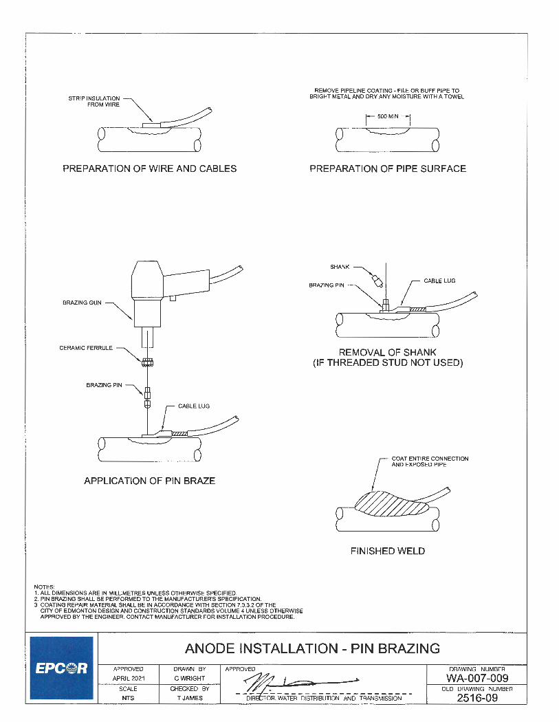
STRIP INSULATION ~
"o~w,., ~
PREPARATION OF WIRE AND CABLES
BRAZING GUN ~
APPLICATION OF PIN BRAZE
NOTES: 1. ALL DIMENSIONS ARE IN MILLIMETRES UNLESS OTHERWISE SPECIFIED. 2. PIN BRAZING SHALL BE PERFORMED TO THE MANUFACTURER'S SPECIFICATION. 3. COATING REPAIR MATERIAL SHALL BE IN ACCORDANCE WITH SECTION 7.3.3.2 OF THE
CITY OF EDMONTON DESIGN AND CONSTRUCTION STANDARDS VOLUME 4 UNLESS OTHERWISE APPROVED BY THE ENGINEER. CONTACT MANUFACTURER FOR INSTALLATION PROCEDURE.
REMOVE PIPELINE COATING - FILE OR BUFF PIPE TO BRIGHT METAL AND DRY ANY MOISTURE WITH A TOWEL
I 500MIN 1
2 a PREPARATION OF PIPE SURFACE
REMOVAL OF SHANK (IF THREADED STUD NOT USED)
r COAT ENTIRE CONNECTION AND EXPOSED PIPE
~ FINISHED WELD
ANODE INSTALLATION - PIN BRAZING APPROVED
APRIL2021
SCALE
NTS
DRAWN BY
CWRIGHT
CHECKED BY
TJAMES
APPROVED
~ le=, -DIR T:;:, WATER DISTRIBUTION AND TRANSMISSION
DRAWING NUMBER
WA-007-009 OLD DRAWING NUMBER
2516-09

NOTES:
WALL (ENTRANCE WALL)
12" (300mm) MIN
METER & FILLPIECE SPACE
i---------- "A" --------7 r- INLETVALVE OUTLETVALVE
/ (SEE NOTE 3)
1 FLOOR
(GRADE WALL)
PIPE SIZE "A" "B" Max. "B"Min. f(16mm) 11 2·-12• (292-305mm) 36" (900mm) 24" (600mm)
j· (20mm) 13 2"-14" (343-356mm) 36" (900mm) 24" (600mm)
1"(25mm) 15 2·-15· (394406mm) 36" (900mm) 24" (600mm)
12· (40mm) 30" (762mm) 24" (610mm) 18"(450mm)
1. METER SETTINGS CONSTRUCTED USING PLASTIC PIPING SHALL HAVE ADEQUATE ANCHORING ON EACH SIDE OF THE METER CAPABLE OF KEEPING THE PIPE IN ALIGNMENT AND SUPPORTING THE WEIGHT OF THE METER, PIPE AND ALL OTHER COMPONENTS.
2. MINIMUM DISTANCE OF CENTERLINE OF PIPING ADJACENT TO METER SETTING TO BE 12" (300mm) FROM ANY ENTRANCE, WALL OR GRADE WALL. MINIMUM 3' (1000mm) WITH NO OBSTRUCTION IN FRONT OF METER.
3. VALVE IS REQUIRED ON OUTLET SIDE OF METER SETTING ON PIPING 1" (25mm) AND OVER. VALVE OPTIONAL ON PIPING UNDER 1" (25mm).
4. PIPING FOR "A" MUST BE IN A HORIZONTAL PLANE. 5. VALVES OR FITTINGS ON SIDES CONNECTING TO METER MUST BE FEMALE THREADED IN • (13mm) FOR
"(16mm) METER; "(20mm) FOR "(20mm) METER; AND 1" (25mm) FOR 1" (25mm) METERS. IF 1 " (32mm) PIPING IS USED. SPACING AND FITTINGS FOR A 1 "(40mm) PIPE MUST BE PROVIDED.
6. BUILDINGS WITH MORE THAN ONE METER MUST HAVE A METAL OR PLASTIC TAG SECURELY ATTACHED TO THE CONTROL VALVE HANDLE OF THE METER IT SERVES. THE TAG MUST HAVE THE SERVICE ADDRESS ENGRAVED ON IT IN LETTERS OR NUMBERS AT LEAST 5mm (")IN HEIGHT. LAWN SERVICES MUST ALSO BE IDENTIFIED WITH TAGS.
"C"Min. 18"{450mm)
18" (450mm)
18" (450mm)
12· (300mm)
7. PREMISES ISOLATION OF THE WATER SUPPLY (FIRE, DOMESTIC, IRRIGATION, OTHER) IS MANDATORY FOR ALL COMMERCIAL, INDUSTRIAL, AND MULTI-RESIDENTIAL BUILDINGS. APPROVED ASSEMBLIES MUST BE SELECTED, INSTALLED, AND TESTED AS PER CSA 664.10.
8. OUTFLOW AND INFLOW SIDES OF METER SETTING TO BE ADEQUATELY SUPPORTED.
SPECIFICATION FOR METER SETTINGS WITHOUT FIRE PROTECTION SYSTEM
l--_:_:_:_~_~_:_~z_D1---l--~-RA-W_:_~G_:_;_-.; APPROVE~D ::z 5- ___.
SCALE CHECKED BY ----=-- ~
NTS D MATHEW - D . WATER. DISTRIBUTION AND TRANSMISSION - -
DRAWING NUMBER
WA-012-001 OLD DRAWING NUMBER
2520-01

WALL (ENTRANCE WALL)
12" (300mm) MIN
BACKFLOW PREVENTER \
METER & FILLPIECE SPACE
~ DOMESTIC WATER / INLET VALVE
ome.vM.,e J (SEE NOTE 3) iii
1
PIPE SIZE "A II "B" Max. "B"Min. j· (16mm) 11 ,·.12· (292-305mm) 36" (900mm) 24" (600mm)
i• (20mm) 13 ,·.14• (343-356mm) 36" (900mm) 24" (600mm)
1"(25mm) 15 ,·.15• (394-406mm) 36" (900mm) 24" (600mm)
1,· (40mm) 30" (762mm) 24" (610mm) 18" (450mm)
NOTES:
FLOOR (GRADE WALL)
"C"Min. 18" (450mm)
18" (450mm)
18" (450mm)
12" (300mm)
1. METER SETIINGS CONSTRUCTED USING PLASTIC PIPING SHALL HAVE ADEQUATE ANCHORING ON EACH SIDE OF THE METER CAPABLE OF KEEPING THE PIPE IN ALIGNMENT AND SUPPORTING THE WEIGHT OF THE METER, PIPE AND ALL OTHER COMPONENTS.
2. MINIMUM DISTANCE OF CENTERLINE OF PIPING ADJACENT TO METER SETIING TO BE 12' (300mm) FROM ANY ENTRANCE, WALL OR GRADE WALL. MINIMUM 3' (1000mm) WITH NO OBSTRUCTION IN FRONT OF METER.
3. VALVE IS REQUIRED ON OUTLET SIDE OF METER SETIING ON PIPING 1" (25mm) AND OVER. VALVE OPTIONAL ON PIPING UNDER 1" (25mm).
4. PIPING FOR "A" MUST BE IN A HORIZONTAL PLANE. 5. VALVES OR FITIINGS ON SIDES CONNECTING TO METER MUST BE FEMALE THREADED IN "(13mm) FOR
"(16mm) METER; "(20mm) FOR "(20mm) METER; AND 1" (25mm) FOR 1" (25mm) METERS. IF 1 " (32mm) PIPING IS USED, SPACING AND FITIINGS FOR A 1 "(40mm) PIPE MUST BE PROVIDED.
6. CONTACT EPCOR WATER SERVICES INC. AT 780-412-4500 PRIOR TO INSTALLATION OF A SYSTEM WHICH WILL METER BOTH FIRE SUPPLY AND DOMESTIC SUPPLY LINES.
7. BUILDINGS WITH MORE THAN ONE METER MUST HAVE A METAL OR PLASTIC TAG SECURELY ATTACHED TO THE CONTROL VALVE HANDLE OF THE METER IT SERVES. THE TAG MUST HAVE THE SERVICE ADDRESS ENGRAVED ON IT IN LETIERS OR NUMBERS AT LEAST 5mm (")IN HEIGHT. LAWN SERVICES MUST ALSO BE IDENTIFIED WITH TAGS.
8. PREMISES ISOLATION OF THE WATER SUPPLY (FIRE, DOMESTIC, IRRIGATION, OTHER) IS MANDATORY FOR ALL COMMERCIAL, INDUSTRIAL, AND MULTI-RESIDENTIAL BUILDINGS. APPROVED ASSEMBLIES MUST BE SELECTED, INSTALLED, AND TESTED AS PER CSA B64.10.
9. OUTFLOW AND INFLOW SIDES OF METER SETIING TO BE ADEQUATELY SUPPORTED.
SPECIFICATIONS FOR METER SETTINGS WITH FIRE PROTECTION SYSTEM
1-
--AP_P_R_o_v_E_D _ __,,___D_RA_W_N_B_Y _ __. APPROVED .' /7 ~ _, APRIL2021 CWRIGHT ~ , ~
SCALE CHECKED BY
NTS D MATHEW DIRECTOR, A;ER DISTRIBUTION AND TRANSMISSION
DRAWING NUMBER
WA-012-002 OLD DRAWING NUMBER
2520-02

FIRE PROTECTION
SUPPLY
Pipe Size Minimum Floor Area Required
inche mm lengt
2· 50 5ft.
3" 75 7ft.
4• 100 7ft.
6" 150 6ft.
B C D Pipe Size A minimum maximum minimum minimum
inches mm in . mm In. mm in. mm
2· 50 36 900 15 375 16 450
3" 75 42 1050 15 375 16 450
4• 100 42 1050 15 375 18 450
6" 150 48 1200 18 450 18 450
NOTES: 1. METER SETIINGS CONSTRUCTED USING PLASTIC PIPING SHALL HAVE ADEQUATE ANCHORING ON EACH SIDE OF THE
METER CAPABLE OF KEEPING THE PIPE IN ALIGNMENT AND SUPPORTING THE WEIGHT OF THE METER. PIPE AND ALL OTHER COMPONENTS.
2. VALVEX & Y MUST BE FEMALE THREADED OR FLANGED AND CANNOT BE BUTIERFLY VALVES. 3. PIPE SIZES FROM " (16mm) TO 2" (62.5mm) TO BE THREADED. PIPE SIZES 3" (75mm) AND LARGER TO
BE FLANGED. 4. VALVE Z MAY BE LOCATED AT ANY POINT ON THE BYPASS, PROVIDED THAT IT IS ALWAYS WITHIN THE 66" (1675mm)
MAXIMUM DISTANCE FROM THE FLOOR. 5. THE MAIN PIPE ALIGNMENT MUST BE A MINIMUM 18" (450mm) FROM ANY WALL, PARTITION, FIXTURE, OR OTHER PIPING. 6. THE SPACE ABOVE FLOOR AREA C X E MUST BE FREE FROM OBSTRUCTIONS TO A HEIGHT OF 78" (1980mm).
in.
36
36
36
36
7. ALL COMBINED DOMESTIC AND FIRE PROTECTION SUPPLY SERVICES MUST HAVE A MASTER CONTROL VALVE BEFORE DOMESTIC SUPPLY TAKE· OFF. NO OTHER VALVE TO CONTROL FIRE PROTECTION SUPPLY EXCEPT BACKFLOW PREVENTER.
6. WATER SERVICE PIPING OUTSIDE BUILDING AND THROUGH BUILDING WALL TO BE INSTALLED IN ACCORDANCE WITH THE EPCOR WATERWORKS BYLAW #12565, AS AMENDED.
9. CONTACT EPCOR WATER SERVICES INC. AT 780-412-4500 PRIOR TO INSTALLATION OF A SYSTEM WHICH WILL METER BOTH FIRE SUPPLY AND DOMESTIC SUPPLY LINES.
10. BUILDINGS WITH MORE THAN ONE METER MUST HAVE A METAL OR PLASTIC TAG SECURELY ATIACHED TO THE CONTROL VALVE HANDLE OF THE METER IT SERVES. THE TAG MUST HAVE THE SERVICE ADDRESS ENGRAVED ON IT IN LETTERS OR NUMBERS AT LEAST 5mm (3/16") IN HEIGHT. LAWN SERVICES MUST ALSO BE IDENTIFIED WITH TAGS.
11 . PREMISES ISOLATION OF THE WATER SUPPLY (FIRE, DOMESTIC, IRRIGATION, OTHER) IS MANDATORY FOR ALL COMMERCIAL, INDUSTRIAL, AND MULTI-RESIDENTIAL BUILDINGS. APPROVED ASSEMBLIES MUST BE SELECTED, INSTALLED, AND TESTED AS PERCSAB64.10.
12. OUTFLOW AND INFLOW SIDES OF METER SETIING TO BE ADEQUATELY SUPPORTED. MINIMUM 6" (150mm) CLEARANCE BETWEEN INFLOW/OUTFLOW PIPES OF METER AND WALL.
mm in . mm
900 18 450
900 18 450
900 18 450
900 18 450
SPECIFICATION FOR METER SETTINGS WITH HORIZONTAL BYPASSES
APPROVED
APRIL 2021
DRAWN BY
CWRIGHT
1.5m
E H minimum minimum in. mm in. mm
46 1200 15 375
54 1350 15 375
60 1525 15 375
66 1675 15 375
DRAWING NUMBER
WA-012-003 SCALE
NTS
CHECKED BY
DMATHEW
OLD DRAWING NUMBER
DIRECTOR, WATER DISTRIBUTION AN D TRANSMISSION 2520-03

FIRE PROTECTION
SUPPLY
Pipe Size Minimum Floor Area Required
inch lengt width area lengt width area
2" 50
3" 75
4• 100
6" 150
B C D E Pipe Size A minimum maximum minimum minimum mm1mum
inches mm in. mm in. mm in. mm in. mm in. mm in. mm
2· 50 36 900 15 375 18 450 36 900 18 450 48 1200
3• 75 42 1050 15 375 18 450 36 900 18 450 54 1350
4• 100 42 1050 15 375 18 450 36 900 18 450 60 1525
6" 150 48 1200 18 450 18 450 36 900 18 450 66 1675
NOTES: 1. METER SETTINGS CONSTRUCTED USING PLASTIC PIPING SHALL HAVE ADEQUATE ANCHORING ON EACH SIDE OF THE METER
CAPABLE OF KEEPING THE PIPE IN ALIGNMENT AND SUPPORTING THE WEIGHT OF THE METER, PIPE AND ALL OTHER COMPONENTS. 2. VALVE X & Y MUST BE FEMALE THREADED OR FLANGED AND CANNOT BE BUTTERFLY VALVES. 3. VALVE Z MAY BE LOCATED AT ANY POINT ON THE BYPASS, PROVIDED THAT IT IS ALWAYS WITHIN THE 66" (1675mm)
MAXIMUM DISTANCE FROM THE FLOOR. 4. THE MAIN PIPE ALIGNMENT MUST BE A MINIMUM 18" {450mm) FROM ANY WALL, PARTITION, FIXTURE, OR OTHER PIPING. 5. THE SPACE ABOVE FLOOR AREA C XE MUST BE FREE FROM OBSTRUCTIONS TO A HEIGHT OF 78" {1980mm). 6. ALL COMBINED DOMESTIC AND FIRE PROTECTION SUPPLY SERVICES MUST HAVE A MASTER CONTROL VALVE BEFORE
DOMESTIC SUPPLY TAKE - OFF. NO OTHER VALVE TO CONTROL FIRE PROTECTION SUPPLY EXCEPT BACKFLOW PREVENTER. 7. WATER SERVICE PIPING OUTSIDE BUILDING AND THROUGH BUILDING WALL TO BE INSTALLED IN ACCORDANCE WITH
THE EPCOR WATERWORK BYLAW#12585, AS AMENDED. 8. CONTACT EPCOR WATER SERVICES INC. AT 780-412-4500 PRIOR TO INSTALLATION OF A SYSTEM WHICH WILL METER BOTH
FIRE SUPPLY AND DOMESTIC SUPPLY LINES. 9. BUILDINGS WITH MORE THAN ONE METER MUST HAVE A METAL OR PLASTIC LOG SECURELY ATTACHED TO THE
CONTROL VALVE HANDLE OF THE METER IT SERVES. THE TAG MUST HAVE THE SERVICE ADDRESS ENGRAVED ON IT IN LETTERS OR NUMBERS AT LEAST 5mm (3/16') IN HEIGHT. LAWN SERVICES MUST ALSO BE IDENTIFIED WITH TAGS.
10. PREMISES ISOLATION OF THE WATER SUPPLY {FIRE, DOMESTIC, IRRIGATION, OTHER) IS MANDATORY FOR ALL COMMERCIAL, INDUSTRIAL, AND MUL Tl-RESIDENTIAL BUILDINGS. APPROVED ASSEMBLIES MUST BE SELECTED, INSTALLED, AND TESTED AS PER CSA B64.10.
11 . OUTFLOW AND INFLOW SIDES OF METER SETTING TO BE ADEQUATELY SUPPORTED.
5ft. 4.5ft. ;J-l 1.5m 1.4m 2.1
sq. m
7ft. 4.5ft. 31 .5
2.1m 1.4m 2.9
s . ft. sq. m.
7ft. 4.5ft. 31.5 2.1 m 1.4m
2.9 sq. ft. sq. m.
8ft. 4 .5ft. 36.0 2.4m 1.4m 3.4 sq. ft. sq. m.
F G minimum maximum maximum in. mm in. mm in. mm
18 450 24 610 48 1200
18 450 24 610 48 1200
18 450 24 610 48 1200
18 450 24 610 48 1200
SPECIFICATIONS FOR METER SETTINGS WITH VERTICAL BYPASSES
APPROVED
APRIL2021
SCALE
NTS
DRAWN BY
CWRIGHT
CHECKED BY
DMATHEW
DRAWING NUMBER
WA-012-004 OLD DRAWING NUMBER
2520-04

Domestic Supply
PIPE SIZE "A"
i"(16mm) 11 ~·-12· (292-305mm)
f (20mm) 13 ~·-14· (343-356mm)
1"(25mm) 15 ~--1 s· (394-406mm)
1 ~· (40mm) 30" (762mm)
NOTES: 1. METER SETIINGS CONSTRUCTED USING PLASTIC PIPING SHALL HAVE ADEQUATE ANCHORING ON EACH SIDE OF THE
METER CAPABLE OF KEEPING THE PIPE IN ALIGNMENT AND SUPPORTING THE WEIGHT OF THE METER, PIPE AND ALL OTHER COMPONENTS.
2. PLUMBERS ARE REQUESTED TO ADVISE EPCOR WATER SERVICES INC. AT 760-412-4500 IN ADVANCE REGARDING EACH INDIVIDUAL INSTALLATION.
3. MASTER CONTROL VALVE TO BE INSTALLED. 4. AN INLET VALVE AND AN OUTLET VALVE MUST BE INSTALLED FOR EACH METER SETIING. 5. VALVES OR FITIINGS ON SIDES CONNECTING TO METER MUST BE FEMALE THREADED IN "(13mm) FOR
"(16mm) METER; "(20mm) FOR "(20mm) METER; AND 1" (25mm) FOR 1" (25mm) METERS. IF 1 "(32mm) PIPING IS USED, SPACING AND FITIING FOR A 1 "(40mm) PIPE MUST BE PROVIDED.
6. FOR METERS LARGER THAN 1 "(40mm) CONTACT EPCOR WATER SERVICES INC. AT 780-412-4500 FOR FURTHER INFORMATION. 7. BUILDINGS WITH MORE THAN ONE METER MUST HAVE A METAL OR PLASTIC TAG SECURELY ATIACHED TO THE
CONTROL VALVE HANDLE OF THE METER IT SERVES. THE TAG MUST HAVE THE SERVICE ADDRESS ENGRAVED ON IT IN LETTERS OR NUMBERS AT LEAST 5mm (3/16") IN HEIGHT. LAWN SERVICES MUST ALSO BE IDENTIFIED WITH TAGS.
8. PREMISES ISOLATION OF THE WATER SUPPLY (FIRE, DOMESTIC, IRRIGATION, OTHER) IS MANDATORY FOR ALL COMMERCIAL, INDUSTRIAL, AND MULTI-RESIDENTIAL BUILDINGS. APPROVED ASSEMBLIES MUST BE SELECTED, INSTALLED, AND TESTED AS PER CSA B64.10.
9. OUTFLOW AND INFLOW SIDES OF METER SETTING TD BE ADEQUATELY SUPPORTED. 10. MINIMUM DISTANCE OF CENTERLINE OF PIPING ADJACENT TO METER SETIING TO BE 12" (300mm) FROM ANY
ENTRANCE, WALL OR GRADE WALL. MINIMUM 3' (1000mm) WITH NO OBSTRUCTION IN FRONT OF METER.
30" (750mm)
SPECIFICATIONS FOR MULTIPLE METERS (METER BANK) WITHOUT FIRE PROTECTION SYSTEM
APPROVED
APRIL2021
SCALE
NTS
DRAWN BY
CWRIGHT
CHECKED BY
DMATHEW
APPROVED.....-:?'.
#/;;2..; -DIRE~~. °0ATrn DISTRIBUTION AND TRANSMISSION
DRAWING NUMBER
WA-012-005 OLD DRAWING NUMBER
2520-05

NOTES:
FIRE PROTECTION
SUPPLY
t
DOMESTIC SUPPLY
I .---.--- - '
I ,,
PIPE SIZE
ff"(16mm)
i' (20mm)
1"(25mm)
1 ~· (40mm)
" A"
11 ~"-12" (292-305mm)
13 ~"-14" (343-356mm)
15 ~· -16' (394-406mm)
30" (762mm)
1. METER SETTINGS CONSTRUCTED USING PLASTIC PIPING SHALL HAVE ADEQUATE ANCHORING ON EACH SIDE OF THE METER CAPABLE OF KEEPING THE PIPE IN ALIGNMENT AND SUPPORTING THE WEIGHT OF THE METER, PIPE AND ALL OTHER COMPONENTS.
2. PLUMBERS ARE REQUESTED TO ADVISE EPCOR WATER SERVICES INC. AT 780-412-4500 IN ADVANCE REGARDING EACH INDIVIDUAL INSTALLATION.
3. MASTER CONTROL VALVE TO BE INSTALLED. 4. AN INLET VALVE AND AN OUTLET VALVE MUST BE INSTALLED FOR EACH METER SETTING. 5. VALVES OR FITTINGS ON SIDES CONNECTING TO METER MUST BE FEMALE THREADED IN ' (13mm) FOR
"(16mm) METER; " (20mm) FOR "(20mm) METER; AND 1' (25mm) FOR 1" (25mm) METERS. IF 1 "(32mm) PIPING IS USED, SPACING AND FITTING FOR A 1 " (40mm) PIPE MUST BE PROVIDED.
6. FOR METERS LARGER THAN 1 • (40mm) CONTACT EPCOR WATER SERVICES INC. AT 780-412-4500 FOR FURTHER INFORMATION. 7. CONTACT EPCOR WATER SERVICES INC. AT 780-412-4500 PRIOR TO INSTALLATION OF A SYSTEM WHICH WILL METER BOTH
FIRE SUPPLY AND DOMESTIC SUPPLY LINES. 8. BUILDINGS WITH MORE THAN ONE METER MUST HAVE A METAL OR PLASTIC TAG SECURELY ATTACHED TO THE
CONTROL VALVE HANDLE OF THE METER IT SERVES. THE TAG MUST HAVE THE SERVICE ADDRESS ENGRAVED ON IT IN LETTERS OR NUMBERS AT LEAST 5mm (3/16") IN HEIGHT. LAWN SERVICES MUST ALSO BE IDENTIFIED WITH TAGS.
9. PREMISES ISOLATION OF THE WATER SUPPLY (FIRE, DOMESTIC, IRRIGATION, OTHER) IS MANDATORY FOR ALL COMMERCIAL, INDUSTRIAL, AND MULTI-RESIDENTIAL BUILDINGS. APPROVED ASSEMBLIES MUST BE SELECTED, INSTALLED, AND TESTED AS PER CSA 664.10.
10. OUTFLOW AND INFLOW SIDES OF METER SETTING TO BE ADEQUATELY SUPPORTED. 11. MINIMUM DISTANCE OF CENTERLINE OF PIPING ADJACENT TO METER SETTING TO BE 12" (300mm) FROM ANY
ENTRANCE, WALL OR GRADE WALL. MINIMUM 3' (1000mm) WITH NO OBSTRUCTION IN FRONT OF METER.
SPECIFICATIONS FOR MULTIPLE METERS (METER BANK) WITH FIRE PROTECTION SYSTEM
1---:_:_:_~-~-:-~2-D1----1--~-RA-w_:_:_:_~--l APPROVED . '2 > -SCALE CHECKED BY /},,;# NTS DMATHEW ~R?6oR,WATER DISTRIBUTION AND TRANSMISSION
DRAWING NUMBER
WA-012-006 OLD DRAWING NUMBER
2520-06

WALL (ENTRANCE WALL)
OUTLETVALVE ~
------ ---------- --~ 1---~~~~~~" A "
METER & FILLPIECE SPACE
BACKFLOW PREVENTER
DOMESTIC SUPPLY OR RINK SERVICE
t
LAWN, ~ DOMi:TIC,
RINK SERVICE
BACKFLOW PREVENTER
NOTES:
12"
(300mm) Min.
~ _, u.
PIPE SIZE
g"(16mm)
i"(20mm}
1"(25mm)
1 i" (40mm)
,-.~~~~~~ • A • ~~~~~~__.
METER & FILLPIECE SPACE DOMESTIC WATER VALVE
u
"A "
11 ,·-12· (292-305mm}
13 ,·-14• (343-356mm)
15 ,'-16" (394-406mm)
30" (762mm}
FLOOR (GRADE WALL)
" B " MAX "B"MIN
36" (900mm) 24" (600mm)
36" (900mm) 24"(600mm}
36" (900mm) 24"(600mm}
24" (610mm} 18"(450mm)
a,
"C " MIN
18" (450mm}
18"(450mm}
18"(450mm}
12" (300mm}
1. METER SETTINGS CONSTRUCTED USING PLASTIC PIPING SHALL HAVE ADEQUATE ANCHORING ON EACH SIDE OF THE METER CAPABLE OF KEEPING THE PIPE IN ALIGNMENT AND SUPPORTING THE WEIGHT OF THE METER, PIPE AND ALL OTHER COMPONENTS.
2. MINIMUM DISTANCE OF CENTERLINE OF PIPING ADJACENT TO METER SETTING TO BE 12" (300mm) FROM ANY ENTRANCE, WALL OR GRADE WALL. MINIMUM 3' (1000mm) WITH NO OBSTRUCTION IN FRONT OF METER.
3. VALVE IS REQUIRED ON OUTLET SIDE OF METER SETTING ON PIPING 1" (25mm) AND OVER. VALVE OPTIONAL ON PIPING UNDER 1" (25mm}.
4. PIPING FOR "A" MUST BE IN A HORIZONTAL PLANE. 5. VALVES OR FITTINGS ON SIDES CONNECTING TO METER MUST BE FEMALE THREADED IN "(13mm) FOR
" (16mm) METER; • (20mm} FOR • (20mm} METER; AND 1• (25mm) FOR 1• (25mm) METERS. IF 1 "(32mm) PIPING IS USED, SPACING AND FITTINGS FOR A 1 • (40mm) PIPE MUST BE PROVIDED.
6. CONTACT EPCOR WATER SERVICES INC. AT 780-412-4500 PRIOR TO INSTALLATION OF A SYSTEM WHICH WILL METER BOTH FIRE SUPPLY AND DOMESTIC SUPPLY LINES.
7. BUILDINGS WITH MORE THAN ONE METER MUST HAVE A METAL OR PLASTIC TAG SECURELY ATTACHED TO THE CONTROL VALVE HANDLE OF THE METER IT SERVES. THE TAG MUST HAVE THE SERVICE ADDRESS ENGRAVED ON IT IN LETTERS OR NUMBERS AT LEAST 5mm (")IN HEIGHT. LAWN SERVICES MUST ALSO BE IDENTIFIED WITH TAGS.
8. PREMISES ISOLATION OF THE WATER SUPPLY (FIRE, DOMESTIC, IRRIGATION, OTHER) IS MANDATORY FOR ALL COMMERCIAL, INDUSTRIAL, AND MUL Tl-RESIDENTIAL BUILDINGS. APPROVED ASSEMBLIES MUST BE SELECTED, INSTALLED, AND TESTED AS PER CSA B64.10.
9. OUTFLOW AND INFLOW SIDES OF METER SETTING TO BE ADEQUATELY SUPPORTED. MINIMUM 6" (150mm} CLEARANCE BETWEEN INFLOW/OUTFLOW PIPES OF METER AND WALL.
SPECIFICATION FOR METER SETTINGS WITH FIRE RINK SERVICE
APPROVED
APRIL 2021
SCALE
NTS
DRAWN BY
CWRIGHT_
CHECKED BY
DMATHEW
APPROVED DRAWING NUMBER
WA-012-007 OLD DRAWING NUMBER
CTOR, WATER DISTRIBUTION AND TRANSMISSION 2520-07

e E
0 0 N
&,
"
NOTE:
E E
0 0
~
l__
a:: w ~ Cl. Cl)
w Cl. a: e E
0
"' b
w Cl. a: e .§ "' io
1. PREMISES ISOLATION OF THE WATER SUPPLY (FIRE, DOMESTIC, IRRIGATION, OTHER) IS MANDATORY FOR ALL COMMERCIAL, INDUSTRIAL, AND MULTI-RESIDENTIAL BUILDINGS. APPROVED ASSEMBLIES MUST BE SELECTED, INSTALLED, AND TESTED AS PER CSA 864.10.
a:: w (.) :::) 0 w a:: (.)
~ z w (.) z 0 (.)
e E
0 0
~
e E fis
b
TYPICAL INSTALLATION OF A 100mm (4") WATER METER
l---:P_p;_~_~2_v~_;_1 -+--~_:_:_~G_H_B; _ __, APPROVED ~ _z 5 ---SCALE CHECKED BY
NTS D MATHEW DIRECTO , ATER DISTRIBUTION AND TRANSMISSION
DRAWING NUMBER
WA-012-008 OLD DRAWING NUMBER
2520-08

It~
z~
21
""
-4
)>
1:IJ
00
fn
~ 2
"'m
~
0
I m
0
~
r ()
0
m
;::
m ~
~ )>
()
0 --
t;:,
; ::
cm
G'i
z
-I
m o
::c
a,
~ ~
--t
-<
;a
0 s: )>
G) z m
~I~
-I
~I
• 0
g:)1 I
, "i
1 0 Vi
I :rl
1 r
~I
0 ::
!I
~
~I
> I
s: z
l 0
1
--<1
m
?; I
-I
z cn1
m
t!i1
;a
211
~I
)>
I en
en
m
0
s: 5
:E 0
OJ
"'
0 )>
?;
r 01
?; I
§ -<
"'~ o
z
oz ...
....
Gl
I G
l "'z
O
z
I C
(.0
C as
: ;::
0
~
a,
<.O
JJ
m
JJ
SE
NS
OR
PO
WE
R A
ND
C
OM
MU
NIC
AT
ION
CA
BL
E
TO
TR
AN
SM
ITT
ER
BO
X
' r B£C
,RO
MA
GH
rnrn
ow
MC
O"
r I
H
I l
FLA
NG
ED
CO
UP
LIN
G A
DA
PT
OR
\
150
LB A
NS
I B
16.5
FL
AN
GE
\
/
FL
AN
GE
D C
OU
PL
ING
AD
AP
TO
R
150
LB A
NS
I B
16.5
FL
AN
GE
PV
C W
AT
ER
MA
IN J
NO
TE
S:
FL
OW
DIR
EC
TIO
N
EL
EC
TR
OM
AG
NE
TIC
FL
OW
ME
TE
R
&
FL
AN
GE
D C
OU
PL
ING
AD
AP
TO
R
-N
.T.S
. •
\ P
VC
WA
TE
R M
AIN
1. I
NS
TA
LL
PR
OM
AG
SIG
NA
L C
AB
LE
AN
D C
OIL
IN
2"
SE
PT
AC
ON
FR
OM
WA
TE
R M
AIN
TO
CA
BIN
ET
P
OLE
LO
CA
TIO
N.
2. I
NS
TA
LL
I.Q
B B
LAC
K,
1-08
RE
D R
WU
90, A
ND
I.Q
B G
RE
EN
RW
U90
(C
CC
) IN
2"
SE
PT
AC
ON
AN
D C
ON
NE
CT
T
O P
OW
ER
LIN
E (
PO
LE O
R U
ND
ER
GR
OU
ND
) .
3. I
NS
TA
LL
IN A
CC
OR
DA
NC
E W
ITH
VO
LU
ME
7 O
F T
HE
CO
E D
ES
IGN
& C
ON
ST
RU
CT
ION
S
TA
ND
AR
DS
. 4
. ALL
EL
EC
TR
ICA
L W
OR
K S
HA
LL
BE
IN
ST
AL
LE
D T
O T
HE
LA
TE
ST
RE
VIS
ION
OF
TH
E C
AN
AD
IAN
E
LE
CT
RIC
AL
CO
DE
. 5
. R
AD
IO A
NT
EN
NA
TO
BE
MO
UN
TE
D A
ND
PO
INT
ED
IN D
IRE
CT
ION
AS
RE
QU
IRE
D B
Y E
PC
OR
WA
TE
R
SC
AD
A G
RO
UP
.
1" L
AT
ER
AL
FO
R~
A
NT
EN
NA
CA
BL
E
"'
CA
BIN
ET
WIT
H M
AIN
~
SE
RV
ICE
EN
TR
AN
CE
"'
!-~
SE
EN
OT
E1
! 6 W
AT
ER
MA
IN
"--
RA
DIO
AN
TE
NN
A
(SE
E N
OT
E 5
)
/ 4
5' W
OO
D P
OLE
-~
ME
TE
R S
OC
KE
T
TO
PO
WE
R L
INE
(S
EE
NO
TE
2)
RA
DIO
AN
TE
NN
A C
ON
NE
CT
ION
DE
TA
IL
• N
.T.S
.·