DESIGN AND CONSTRUCTION STANDARDS FOR SEPTIC TANKS, … · professional engineer (PE): non-domestic...
32
1 Chapter 2 DESIGN AND CONSTRUCTION STANDARDS FOR SEPTIC TANKS, SOIL ABSORPTION SYSTEMS, AND OTHER SMALL WASTEWATER SYSTEMS Section 1. Authority. This regulation is promulgated pursuant to the Wyoming Administrative Procedures Act, W.S. 16-3-101 et seq.; the Wyoming Environmental Quality Act, W.S. 35-11-101 through W.S. 35-11-2004; and W.S. 35-1-301 through 35-1-309. Specifically, W.S. 35-11-301 states that no person, except when authorized by permit, shall: construct, install, modify, or operate any small wastewater facility. W.S. 35-11-304 states that to the extent requested, authority to enforce and administer W.S. 35-11-30 I (a) (iii) and (v) shall be delegated to qualifying municipalities, water and sewer districts or counties. Section 2. Objective. This Chapter contains the minimum standards for the design and construction of small wastewater systems that are defined by W.S. 35-11-103(c)(ix). The following situations will require the application package to be sealed, signed, and dated by a professional engineer (PE): non-domestic wastewater from commercial and industrial facilities, high strength wastewater, individual permits to construct, or standard soil absorption systems with a soil percolation rate that is either less than 5 minutes per inch (mpi) or more than 60 minutes per inch (mpi). These standards pertain to permits required pursuant to Chapters 3 and 25, Wyoming Water Quality Rules and Regulations. The installation of all components of a small wastewater system require a permit to construct. Permits to construct are specified throughout this chapter as individual permits to construct, described in Chapter 3, Section 6 Wyoming Water Quality Rules and Regulations. Section 3. Timing of Compliance with These Regulations. Any permit-to-construct issued for facilities subject to this chapter prior to the effective date of these regulations, and any facility authorized under the Division’s “General Permit to Construct, Install, Modify or Operate a Small Wastewater Facility” shall remain covered under those permits. New construction or modification of existing facilities following the effective date of this regulation must obtain authorization under a new permit. Section 4. Design Flows. The volume of wastewater shall be determined by one of the following: (a) Tables 1 and 2 provided in this section.
Transcript of DESIGN AND CONSTRUCTION STANDARDS FOR SEPTIC TANKS, … · professional engineer (PE): non-domestic...
1
Chapter 2
DESIGN AND CONSTRUCTION STANDARDS FOR SEPTIC TANKS, SOIL ABSORPTION SYSTEMS, AND OTHER SMALL WASTEWATER SYSTEMS
Section 1. Authority. This regulation is promulgated pursuant to the Wyoming Administrative Procedures Act, W.S. 16-3-101 et seq.; the Wyoming Environmental Quality Act, W.S. 35-11-101 through W.S. 35-11-2004; and W.S. 35-1-301 through 35-1-309. Specifically, W.S. 35-11-301 states that no person, except when authorized by permit, shall: construct, install, modify, or operate any small wastewater facility. W.S. 35-11-304 states that to the extent requested, authority to enforce and administer W.S. 35-11-30 I (a) (iii) and (v) shall be delegated to qualifying municipalities, water and sewer districts or counties. Section 2. Objective. This Chapter contains the minimum standards for the design and construction of small wastewater systems that are defined by W.S. 35-11-103(c)(ix). The following situations will require the application package to be sealed, signed, and dated by a professional engineer (PE): non-domestic wastewater from commercial and industrial facilities, high strength wastewater, individual permits to construct, or standard soil absorption systems with a soil percolation rate that is either less than 5 minutes per inch (mpi) or more than 60 minutes per inch (mpi). These standards pertain to permits required pursuant to Chapters 3 and 25, Wyoming Water Quality Rules and Regulations. The installation of all components of a small wastewater system require a permit to construct. Permits to construct are specified throughout this chapter as individual permits to construct, described in Chapter 3, Section 6 Wyoming Water Quality Rules and Regulations. Section 3. Timing of Compliance with These Regulations. Any permit-to-construct issued for facilities subject to this chapter prior to the effective date of these regulations, and any facility authorized under the Division’s “General Permit to Construct, Install, Modify or Operate a Small Wastewater Facility” shall remain covered under those permits. New construction or modification of existing facilities following the effective date of this regulation must obtain authorization under a new permit. Section 4. Design Flows. The volume of wastewater shall be determined by one of the following: (a) Tables 1 and 2 provided in this section.
2
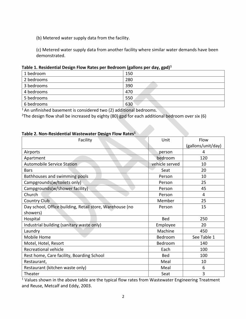
(b) Metered water supply data from the facility.
(c) Metered water supply data from another facility where similar water demands have been demonstrated.
Table 1. Residential Design Flow Rates per Bedroom (gallons per day, gpd)1
1 bedroom 150
2 bedrooms 280
3 bedrooms 390
4 bedrooms 470
5 bedrooms 550
6 bedrooms 630 1 An unfinished basement is considered two (2) additional bedrooms. 2The design flow shall be increased by eighty (80) gpd for each additional bedroom over six (6) Table 2. Non-Residential Wastewater Design Flow Rates1
Facility Unit Flow (gallons/unit/day)
Airports person 4
Apartment bedroom 120
Automobile Service Station vehicle served 10
Bars Seat 20
Bathhouses and swimming pools Person 10
Campgrounds(w/toilets only) Person 25
Campgrounds(w/shower facility) Person 45
Church Person 4
Country Club Member 25
Day school, Office building, Retail store, Warehouse (no showers)
Person 15
Hospital Bed 250
Industrial building (sanitary waste only) Employee 20
Laundry Machine 450
Mobile Home Bedroom See Table 1
Motel, Hotel, Resort Bedroom 140
Recreational vehicle Each 100
Rest home, Care facility, Boarding School Bed 100
Restaurant, Meal 10
Restaurant (kitchen waste only) Meal 6
Theater Seat 3 1 Values shown in the above table are the typical flow rates from Wastewater Engineering Treatment and Reuse, Metcalf and Eddy, 2003.

3
Section 5. Systems Not Specifically Covered by This Rule. This section is provided to encourage new technology and equipment and provide a process for evaluating and permitting designs that deviate from this rule. The proposed construction of facilities and processes not in compliance with this rule may be permitted provided that the facility, when constructed and operated, meets the objective of these rules.
(a) Each application for a permit to construct shall include an engineering design report, detailed construction plans, and technical specifications for all piping, tanks, and equipment. All of the documents shall have a suitable title showing the owner’s name and the Wyoming registration number, seal, and signature of the engineer.
(b) Each application for a permit to construct will be evaluated on a case-by-case basis using the best available technology. The application shall include at least one of the following:
(i) Data obtained from a full scale, comparable installation that demonstrates the acceptability of the design.
(ii) Data obtained from a pilot plant operated under the design condition for a sufficient length of time to demonstrate the acceptability of the design.
(iii) Data obtained from the theoretical evaluation of the design that demonstrates a reasonable probability the facility will meet the design objectives.
(iv) An evaluation of the flexibility of making corrective changes to the constructed facility in the event it does not function as planned.
(c) Monitoring of the performance of any alternative or experimental system installed may be required. The performance monitoring may consist of small wastewater system inspections, effluent sampling, monitoring wells or as determined by the Health Officer.
(d) The minimum frequency and duration of monitoring for alternative or experimental systems shall be determined at the time of permit issuance.
(e) Any additional costs incurred by monitoring shall be borne by the owner. An agreement to that effect shall be signed by the owner prior to approval of any alternative or experimental system.
(f) If an applicant wishes to construct a pilot plant to provide data necessary to show the design will meet the purpose of the act, a permit to construct must be obtained.
4
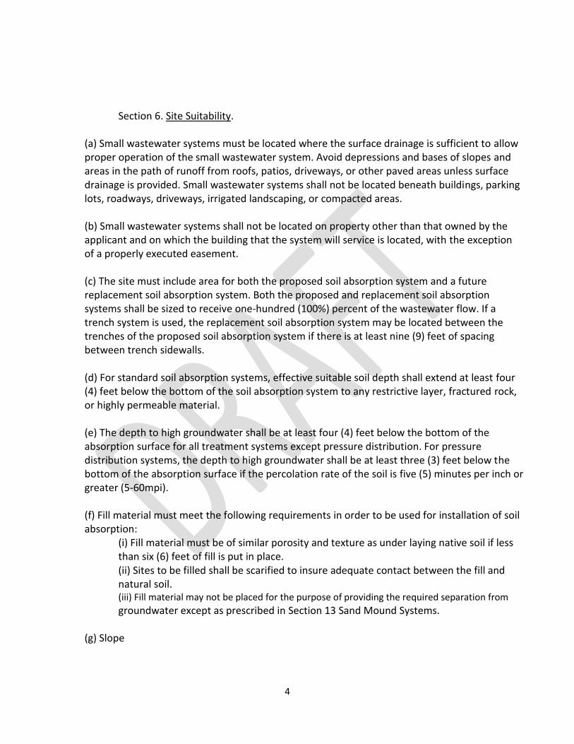
Section 6. Site Suitability.
(a) Small wastewater systems must be located where the surface drainage is sufficient to allow proper operation of the small wastewater system. Avoid depressions and bases of slopes and areas in the path of runoff from roofs, patios, driveways, or other paved areas unless surface drainage is provided. Small wastewater systems shall not be located beneath buildings, parking lots, roadways, driveways, irrigated landscaping, or compacted areas.
(b) Small wastewater systems shall not be located on property other than that owned by the applicant and on which the building that the system will service is located, with the exception of a properly executed easement.
(c) The site must include area for both the proposed soil absorption system and a future replacement soil absorption system. Both the proposed and replacement soil absorption systems shall be sized to receive one-hundred (100%) percent of the wastewater flow. If a trench system is used, the replacement soil absorption system may be located between the trenches of the proposed soil absorption system if there is at least nine (9) feet of spacing between trench sidewalls.
(d) For standard soil absorption systems, effective suitable soil depth shall extend at least four (4) feet below the bottom of the soil absorption system to any restrictive layer, fractured rock, or highly permeable material.
(e) The depth to high groundwater shall be at least four (4) feet below the bottom of the absorption surface for all treatment systems except pressure distribution. For pressure distribution systems, the depth to high groundwater shall be at least three (3) feet below the bottom of the absorption surface if the percolation rate of the soil is five (5) minutes per inch or greater (5-60mpi). (f) Fill material must meet the following requirements in order to be used for installation of soil absorption: (i) Fill material must be of similar porosity and texture as under laying native soil if less than six (6) feet of fill is put in place. (ii) Sites to be filled shall be scarified to insure adequate contact between the fill and natural soil.
(iii) Fill material may not be placed for the purpose of providing the required separation from
groundwater except as prescribed in Section 13 Sand Mound Systems. (g) Slope
5
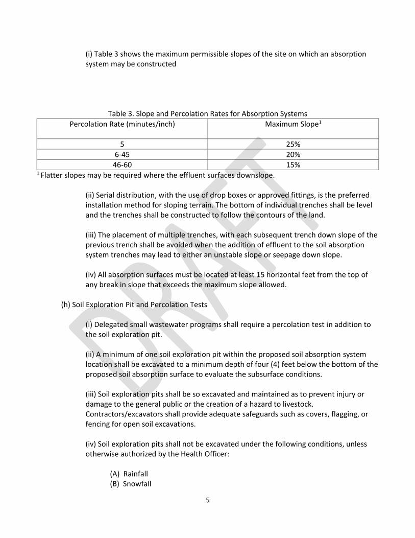
(i) Table 3 shows the maximum permissible slopes of the site on which an absorption system may be constructed
Table 3. Slope and Percolation Rates for Absorption Systems
Percolation Rate (minutes/inch) Maximum Slope1
5 25%
6-45 20%
46-60 15% 1 Flatter slopes may be required where the effluent surfaces downslope.
(ii) Serial distribution, with the use of drop boxes or approved fittings, is the preferred installation method for sloping terrain. The bottom of individual trenches shall be level and the trenches shall be constructed to follow the contours of the land.
(iii) The placement of multiple trenches, with each subsequent trench down slope of the previous trench shall be avoided when the addition of effluent to the soil absorption system trenches may lead to either an unstable slope or seepage down slope.
(iv) All absorption surfaces must be located at least 15 horizontal feet from the top of any break in slope that exceeds the maximum slope allowed.
(h) Soil Exploration Pit and Percolation Tests
(i) Delegated small wastewater programs shall require a percolation test in addition to the soil exploration pit.
(ii) A minimum of one soil exploration pit within the proposed soil absorption system location shall be excavated to a minimum depth of four (4) feet below the bottom of the proposed soil absorption surface to evaluate the subsurface conditions.
(iii) Soil exploration pits shall be so excavated and maintained as to prevent injury or damage to the general public or the creation of a hazard to livestock. Contractors/excavators shall provide adequate safeguards such as covers, flagging, or fencing for open soil excavations.
(iv) Soil exploration pits shall not be excavated under the following conditions, unless otherwise authorized by the Health Officer:
(A) Rainfall (B) Snowfall
6
(C) Frozen ground (D) Soils saturated with water (E) Ambient air temperature below thirty-two (32) degrees Fahrenheit.
(v) The percolation test shall be performed in accordance with Appendix A of this chapter. An evaluation of the soil texture, in the proposed soil absorption system location, by a person experienced in soils classification, may be used as an additional tool to confirm the percolation rate.
(vi) The percolation test shall not be conducted when the ambient air temperature is less than thirty-two (32) degrees Fahrenheit and/or when frost is present in the percolation test zone.
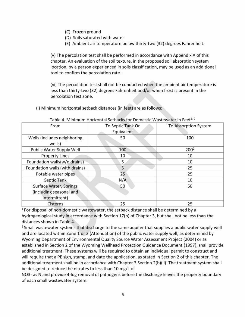
(i) Minimum horizontal setback distances (in feet) are as follows:
Table 4. Minimum Horizontal Setbacks for Domestic Wastewater in Feet1, 2
From To Septic Tank Or Equivalent
To Absorption System
Wells (includes neighboring wells)
50 100
Public Water Supply Well 100 2002
Property Lines 10 10
Foundation walls(w/o drains) 5 10
Foundation walls (with drains) 5 25
Potable water pipes 25 25
Septic Tank N/A 10
Surface Water, Springs (including seasonal and
intermittent)
50 50
Cisterns 25 25 1 For disposal of non-domestic wastewater, the setback distance shall be determined by a hydrogeological study in accordance with Section 17(b) of Chapter 3, but shall not be less than the distances shown in Table 4. 2 Small wastewater systems that discharge to the same aquifer that supplies a public water supply well and are located within Zone 1 or 2 (Attenuation) of the public water supply well, as determined by Wyoming Department of Environmental Quality Source Water Assessment Project (2004) or as established in Section 2 of the Wyoming Wellhead Protection Guidance Document (1997), shall provide additional treatment. These systems will be required to obtain an individual permit to construct and will require that a PE sign, stamp, and date the application, as stated in Section 2 of this chapter. The additional treatment shall be in accordance with Chapter 3 Section 2(b)(ii). The treatment system shall be designed to reduce the nitrates to less than 10 mg/L of NO3- as N and provide 4-log removal of pathogens before the discharge leaves the property boundary of each small wastewater system.
7
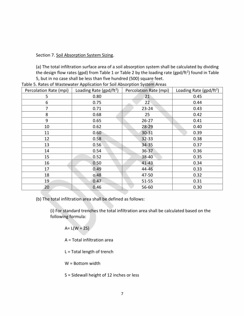
Section 7. Soil Absorption System Sizing.
(a) The total infiltration surface area of a soil absorption system shall be calculated by dividing the design flow rates (gpd) from Table 1 or Table 2 by the loading rate (gpd/ft2) found in Table 5, but in no case shall be less than five hundred (500) square feet.
Table 5. Rates of Wastewater Application for Soil Absorption System Areas
Percolation Rate (mpi) Loading Rate (gpd/ft2) Percolation Rate (mpi) Loading Rate (gpd/ft2)
5 0.80 21 0.45
6 0.75 22 0.44
7 0.71 23-24 0.43
8 0.68 25 0.42
9 0.65 26-27 0.41
10 0.62 28-29 0.40
11 0.60 30-31 0.39
12 0.58 32-33 0.38
13 0.56 34-35 0.37
14 0.54 36-37 0.36
15 0.52 38-40 0.35
16 0.50 41-43 0.34
17 0.49 44-46 0.33
18 o.48 47-50 0.32
19 0.47 51-55 0.31
20 0.46 56-60 0.30
(b) The total infiltration area shall be defined as follows:
(i) For standard trenches the total infiltration area shall be calculated based on the following formula:
A= L(W + 2S) A = Total infiltration area L = Total length of trench W = Bottom width S = Sidewall height of 12 inches or less
8
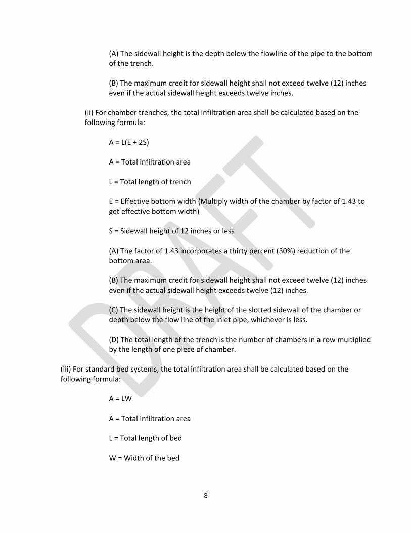
(A) The sidewall height is the depth below the flowline of the pipe to the bottom of the trench.
(B) The maximum credit for sidewall height shall not exceed twelve (12) inches even if the actual sidewall height exceeds twelve inches.
(ii) For chamber trenches, the total infiltration area shall be calculated based on the following formula:
A = L(E + 2S) A = Total infiltration area L = Total length of trench
E = Effective bottom width (Multiply width of the chamber by factor of 1.43 to get effective bottom width)
S = Sidewall height of 12 inches or less
(A) The factor of 1.43 incorporates a thirty percent (30%) reduction of the bottom area.
(B) The maximum credit for sidewall height shall not exceed twelve (12) inches even if the actual sidewall height exceeds twelve (12) inches.
(C) The sidewall height is the height of the slotted sidewall of the chamber or depth below the flow line of the inlet pipe, whichever is less.
(D) The total length of the trench is the number of chambers in a row multiplied by the length of one piece of chamber.
(iii) For standard bed systems, the total infiltration area shall be calculated based on the following formula:
A = LW A = Total infiltration area L = Total length of bed W = Width of the bed
9
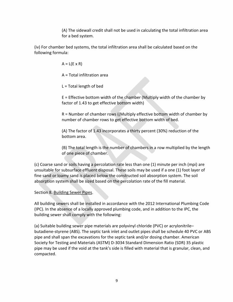
(A) The sidewall credit shall not be used in calculating the total infiltration area for a bed system.
(iv) For chamber bed systems, the total infiltration area shall be calculated based on the following formula:
A = L(E x R) A = Total infiltration area L = Total length of bed
E = Effective bottom width of the chamber (Multiply width of the chamber by factor of 1.43 to get effective bottom width)
R = Number of chamber rows ((Multiply effective bottom width of chamber by number of chamber rows to get effective bottom width of bed.
(A) The factor of 1.43 incorporates a thirty percent (30%) reduction of the bottom area.
(B) The total length is the number of chambers in a row multiplied by the length of one piece of chamber.
(c) Coarse sand or soils having a percolation rate less than one (1) minute per inch (mpi) are unsuitable for subsurface effluent disposal. These soils may be used if a one (1) foot layer of fine sand or loamy sand is placed below the constructed soil absorption system. The soil absorption system shall be sized based on the percolation rate of the fill material.
Section 8. Building Sewer Pipes.
All building sewers shall be installed in accordance with the 2012 International Plumbing Code (IPC). In the absence of a locally approved plumbing code, and in addition to the IPC, the building sewer shall comply with the following:
(a) Suitable building sewer pipe materials are polyvinyl chloride (PVC) or acrylonitrile– butadiene-styrene (ABS). The septic tank inlet and outlet pipes shall be schedule 40 PVC or ABS pipe and shall span the excavations for the septic tank and/or dosing chamber. American Society for Testing and Materials (ASTM) D-3034 Standard Dimension Ratio (SDR) 35 plastic pipe may be used if the void at the tank’s side is filled with material that is granular, clean, and compacted.
10
(b) Building sewer pipes shall be sized to handle the peak hourly flow from the building and shall not be smaller than four (4) inches in diameter. When two different sizes or types of sewer pipes are to be connected, a proper type of fitting or conversion adapter shall be used.
(c) Sewer pipe shall not decrease in size flowing downstream.
(d) Building sewer pipes shall be laid at a standard slope of 1/4 inch per foot, and shall not be flatter than 1/8 inch per foot.
(e) Cleanouts shall be provided between the structure and the tank, at branch connections, every change in alignment, and at least every 100 feet in straight runs.
(f) All sewer piping shall be laid on a firm bed throughout its entire length. It shall be protected from damage due to rocks, hard lumps of soil, debris, and the like.
(g) Special care shall be used to prevent lateral movement or deformation during backfill. The backfill material shall be compacted to a density at least equivalent to the trench walls. Backfill over the pipe shall be of sufficient depth to protect the pipe from expected traffic loads and the wastewater from freezing.
Section 9. Septic Tanks and Other Treatment Tanks.
(a) Septic Tanks
(i) Septic tanks shall be fabricated or constructed of concrete, fiberglass, thermoplastic or an approved material. Tanks shall be watertight and fabricated to constitute an individual structure, and shall be designed and constructed to withstand anticipated loads. All tanks must be approved by the Department of Environmental Quality, Water Quality Division (DEQ/WQD).
(ii) The septic tank shall be placed on a level grade and a firm bedding to prevent settling. Where rock or other undesirable protruding obstructions are encountered, the opening for the septic tank shall be over excavated, as needed, and backfilled with sand, crushed stone, or gravel to the proper grade.
(A) Septic tanks shall not be buried deeper than the tank manufacturer’s maximum designed depth for the tank. The minimum depth of soil cover over the top of the tank is six (6) inches.
(B) Backfill around and over the septic tank shall be placed in such a manner as to prevent undue strain or damage to the tank or connected pipes.
11
(C) Septic tanks shall not be placed in areas subject to vehicular traffic unless engineered for the anticipated load.
(iii) Size
(A) The minimum liquid volume of a septic tank shall be 1000 gallons for residences up to a four (4) bedroom capacity. Additional capacity of 150 gallons per bedroom shall be provided for each bedroom over four (4).
(B) Septic tanks for high strength wastewater or non-residential units shall have a minimum effective liquid capacity sufficient to provide at least 48 hour retention at design flow or 1,000 gallons, whichever is greater.
(iv) Configuration
(A) Single compartment septic tanks shall have a length to width ratio of no less than two (2) to one (1), or be partitioned to protect against short circuiting flow.
(B) Single compartment septic tanks shall have an approved effluent filter installed on the outlet baffle. Effluent filters must meet the following minimum criteria:
(I) One-sixteenth (1/16) to one-quarter (1/4) inch mesh size. Mesh size shall not exceed the diameter of distribution pipe orifices.
(II) Non corrosive material (III) Easily removable for cleaning
(C) For septic tanks with two (2) compartments or more, the inlet compartment shall not be less than one-half (1/2) of the total capacity of the tank.
(D) The liquid depth shall be between three (3) feet and six (6) feet.
(E) The tank partition shall allow the venting of gases between compartments and out through the vent stack on the plumbing system of the house.
(F) The inlet and outlet on all tanks or tank compartments shall be provided with open-ended sanitary tees or baffles made of approved materials constructed to distribute flow and retain scum in the tank or compartments.
(I) The tees or baffles shall extend above the liquid level a minimum distance of five (5) inches.
12
(II) The inlet tees or baffles shall extend below the liquid level at least eight (8) inches but no more than 40% of the liquid level. The outlet tees or baffles shall extend below the liquid level at least ten (10) inches but no more than 45% of the liquid level.
(III) A minimum of one (1) inch of clear space shall be provided over the top of the baffles or tees for venting.
(IV) The inlet pipe shall be at least two (2) inches higher than the outlet pipe. The outlet elevation shall be designed to provide a minimum distance of nine (9) inches or twenty (20) percent of the liquid depth between the top of the liquid and the bottom of the septic tank cover for scum storage and the venting of gases.
(v) If additional septic tank capacity over 1,000 gallons is needed, it may be obtained by joining tanks in series provided the following requirements are met:
(A) The inlet of each successive tank shall be at least two (2) inches lower than the outlet of the preceding tank, and shall have no tee or baffle except for the inlet to the first tank and the outlet for the last tank.
(B) The first tank or the first compartment of the first tank shall be equal to fifty percent (50%) or larger of the total septic tank system volume.
(vi) An access opening shall be provided to each compartment of the septic tank for inspection and cleaning.
(A) The access opening(s) in the cover/lid of the tank shall have a minimum diameter of twenty (20) inches. Both inlet and outlet devices shall be accessible.
(B) The riser from the access opening shall terminate at a maximum of six (6) inches below the ground surface. Riser covers terminating above grade shall have an approved locking device.
(vii) Septic tank inlet and outlet piping shall be affixed to the tank through the use of a non-shrink grout coated with a waterproof material or other method approved by the Health Officer.
(viii) An effluent filter with an opening of 1/8-inch or smaller shall be provided on the outlet of a septic tank or other tank that precedes a small diameter pressure distribution system.
(b) Dosing Tanks
13
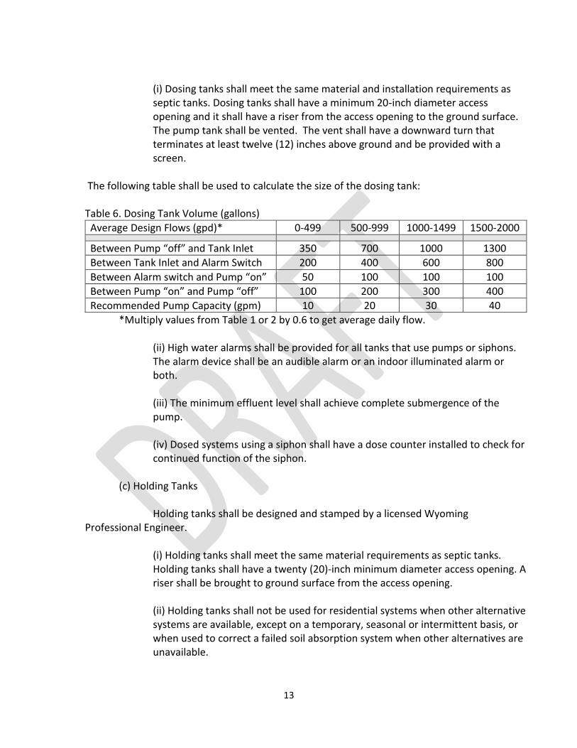
(i) Dosing tanks shall meet the same material and installation requirements as septic tanks. Dosing tanks shall have a minimum 20-inch diameter access opening and it shall have a riser from the access opening to the ground surface. The pump tank shall be vented. The vent shall have a downward turn that terminates at least twelve (12) inches above ground and be provided with a screen.
The following table shall be used to calculate the size of the dosing tank: Table 6. Dosing Tank Volume (gallons)
Average Design Flows (gpd)* 0-499 500-999 1000-1499 1500-2000
Between Pump “off” and Tank Inlet 350 700 1000 1300
Between Tank Inlet and Alarm Switch 200 400 600 800
Between Alarm switch and Pump “on” 50 100 100 100
Between Pump “on” and Pump “off” 100 200 300 400
Recommended Pump Capacity (gpm) 10 20 30 40
*Multiply values from Table 1 or 2 by 0.6 to get average daily flow. (ii) High water alarms shall be provided for all tanks that use pumps or siphons.
The alarm device shall be an audible alarm or an indoor illuminated alarm or both.
(iii) The minimum effluent level shall achieve complete submergence of the pump.
(iv) Dosed systems using a siphon shall have a dose counter installed to check for continued function of the siphon.
(c) Holding Tanks Holding tanks shall be designed and stamped by a licensed Wyoming Professional Engineer. (i) Holding tanks shall meet the same material requirements as septic tanks.
Holding tanks shall have a twenty (20)-inch minimum diameter access opening. A riser shall be brought to ground surface from the access opening.
(ii) Holding tanks shall not be used for residential systems when other alternative systems are available, except on a temporary, seasonal or intermittent basis, or when used to correct a failed soil absorption system when other alternatives are unavailable.
14
(iii) Holding tanks must be located in an area readily accessible to the pump truck and where the tank itself will not float due to high groundwater. If seasonal high groundwater may be present, the tank shall be properly anchored.
(iv) The minimum liquid volume shall be the greater of 1,000 gallons or seven (7) days storage based upon flow rate determined from Section 5.
(v) All holding tanks shall be equipped with a high-water level alarm. The device shall be an audible alarm or an indoor illuminated alarm or both. The device shall be installed so that the alarm is triggered when the water level reaches 3/4 of the tank capacity.
(d) Grease Interceptors
(i) A commercial or institutional food preparation facility with a waste stream containing fat, oil, and grease (FOG) in excess of 25 mg/L shall install an exterior grease interceptor or a device approved by the delegated health department or county. Facilities that typically have waste streams high in FOG are, but not limited to, restaurants, cafeterias, slaughterhouses, and institutional kitchens.
(ii) Waste streams high in FOG shall be plumbed separately and directly to a grease interceptor prior to the waste treatment process.
(iii) Waste streams from sanitary facilities such as bathrooms, toilets, urinals, or other similar fixtures shall not be discharged into the grease interceptor. These sources must be connected at least four to six (4-6) feet downstream of the grease interceptor’s discharge. The design shall prevent any backflow from the sanitary sources into the grease interceptor.
(iv) Only one source facility per grease interceptor shall be allowed.
(v) Grease interceptors shall be located so that they are easily accessible for inspection, cleaning, and removal of the collected wastes. The interceptor shall not be closer than fifteen (15) feet from the last discharging fixture and no further away than thirty-five (35) feet.
(vi) Grease interceptors shall have at least two (2) compartments with a 20-inch minimum diameter access opening for each compartment for cleanout. Each access opening shall have a riser brought to the surface and have a sealed lid that is rated for any anticipated load. There shall be a means provided to sample the effluent.
(vii) There shall be no internal cleanout tees or bypasses.
15
(viii) The inlet and outlet of the grease interceptor shall be vented. The vent pipe shall be at least two (2) inches in diameter. The inlet and outlet vents shall not be interconnected.
(ix) The outlet pipe invert shall be no more than two (2) inches lower than the inlet invert.
(x) The dividing wall between compartments shall be the same height as the other walls and the cover should contact the top of the dividing wall. If the partition/dividing wall does not contact the cover, the outlet tee or baffle shall extend below the liquid level, 40-50% of the total liquid depth.
(xi) The effluent from each compartment shall be drawn from the bottom of a riser pipe that terminates at least eighteen (18) inches below the inlet pipe invert of that same compartment.
(xii) Grease interceptors shall be accessible during normal business hours without interrupting normal business operations.
(xiii) Grease interceptors shall be installed in accordance with the manufacturer’s instructions and applicable requirements of this section. A copy of the manufacturer’s instructions shall be submitted with every permit to construct application submitted to the Casper-Natrona County Health Department.
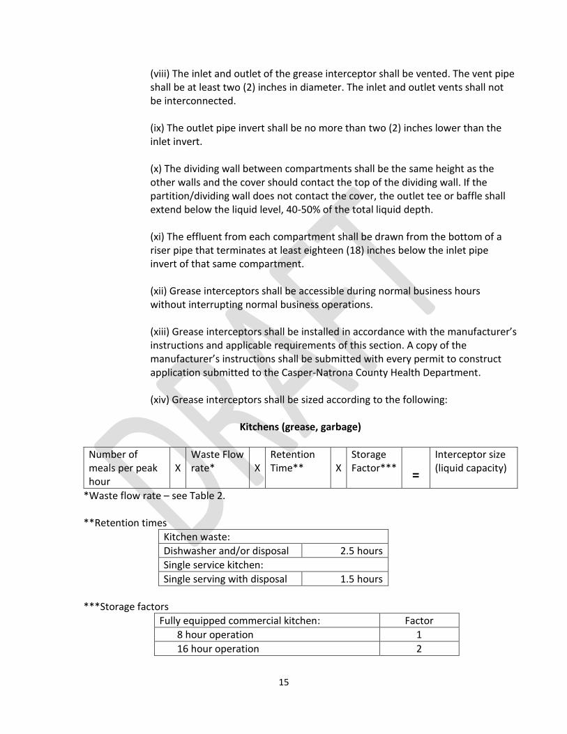
(xiv) Grease interceptors shall be sized according to the following:
Kitchens (grease, garbage)
Number of meals per peak hour
X
Waste Flow rate*
X
Retention Time**
X
Storage Factor***
=
Interceptor size (liquid capacity)
*Waste flow rate – see Table 2. **Retention times
Kitchen waste:
Dishwasher and/or disposal 2.5 hours
Single service kitchen:
Single serving with disposal 1.5 hours
***Storage factors
Fully equipped commercial kitchen: Factor
8 hour operation 1
16 hour operation 2
16
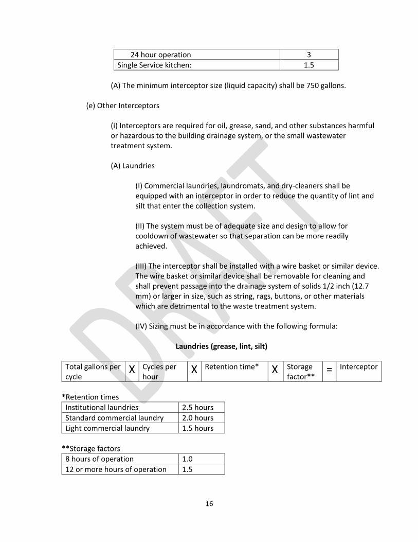
24 hour operation 3
Single Service kitchen: 1.5
(A) The minimum interceptor size (liquid capacity) shall be 750 gallons. (e) Other Interceptors
(i) Interceptors are required for oil, grease, sand, and other substances harmful or hazardous to the building drainage system, or the small wastewater treatment system.
(A) Laundries
(I) Commercial laundries, laundromats, and dry-cleaners shall be equipped with an interceptor in order to reduce the quantity of lint and silt that enter the collection system.
(II) The system must be of adequate size and design to allow for cooldown of wastewater so that separation can be more readily achieved.
(III) The interceptor shall be installed with a wire basket or similar device. The wire basket or similar device shall be removable for cleaning and shall prevent passage into the drainage system of solids 1/2 inch (12.7 mm) or larger in size, such as string, rags, buttons, or other materials which are detrimental to the waste treatment system.
(IV) Sizing must be in accordance with the following formula:
Laundries (grease, lint, silt)
Total gallons per cycle
X Cycles per hour
X Retention time* X Storage factor**
= Interceptor
*Retention times
Institutional laundries 2.5 hours
Standard commercial laundry 2.0 hours
Light commercial laundry 1.5 hours
**Storage factors
8 hours of operation 1.0
12 or more hours of operation 1.5
17
(B) Car Washes
(I) Where automobiles are washed (including detail shops using hand wash practices), separators shall have a minimum capacity of 1000 gallons for the first bay, with an additional 500 gallons of capacity for every other bay.
(II) Additionally, wash racks must be constructed to eliminate or minimize the impact of run-off from rain/storm events. Minimum requirements are roofed structures with at least two walls and appropriate grading to prevent storm water infiltration into the sanitary sewer.
(III) An effluent sampling point is required. (f) Abandonment of Septic and Holding Tanks The following is the procedure to abandon septic tanks and holding tanks when the system is upgraded, equipment replacement is necessary, or central sewer lines are made available.
(i) The abandoned tank should be pumped and the septage hauled to a licensed facility approved to receive the waste or the septage pumped into the newly constructed septic or holding tank. Discharging to a central sewer requires coordination with, and the approval of, the owner/operator of the sewer system.
(ii) Once the abandoned tank is empty, it should be removed and the excavation backfilled. As an alternative to removing the tank, the access covers can be removed; the bottom drilled or broken up sufficient to drain; and the tank filled with native soil, pit run, or sand.
(iii) If the abandoned tank is part of a Class V UIC facility, the abandonment must also be in compliance with Chapter 27, Section 19 of the Wyoming DEQ Water Quality Rules.
Section 10. Effluent Distribution Devices. Distribution boxes and flow divider tees are suitable for level or nearly level ground and are installed before the soil absorption system with the goal of splitting flows equally between soil absorption system laterals. Drop boxes are suitable for sloping ground and are installed to achieve serial loading. (a) Distribution Boxes
(i) The distribution box shall be installed on a level, stable base to prevent tilting or settling, and to minimize movement from frost heave.
18
(ii) Boxes shall be watertight and constructed of concrete or other durable material.
(iii) Boxes shall be designed to accommodate the inlet pipe and the necessary distribution lines.
(iv) The inlet piping to the distribution box shall be at least one (1) inch above the outlet pipes and the outlet inverts shall be no less than four (4) inches above the floor of the box. All pipes shall have a watertight connection to the distribution box.
(v) The box shall be protected against freezing and made accessible for observation and maintenance.
(vi) Boxes shall have flow equalizers installed on each outflow. (b) Flow divider tees may be used in place of distribution boxes. (c) Drop boxes are suitable for sloping ground and are installed to achieve serial loading.
The drop boxes shall meet the requirements in paragraphs (a)(i through vi) of this section.
Section 11. Standard Soil Absorption Systems. (a) General Design Requirements:
(i) All soil absorption systems shall be designed in such a manner that the effluent is effectively filtered and retained below the ground surface. The absorption surface accepts, treats, and disperses wastewater as it percolates through the soil.
(ii) Soil absorption systems shall not be excavated when the soil is wet enough to smear or compact easily. Open soil absorption system excavations shall be protected from surface runoff to prevent the entrance of silt and debris. All smeared or compacted surfaces shall be raked to a depth of one (1) inch, and loose material removed before filter or filler material is placed in the soil absorption system excavation. (iii) Soil absorption systems shall not be installed during adverse or inclement weather.
(iv) Soil absorption systems shall be designed to approximately follow the ground surface contours so that variation in excavation depths will be minimized. The
19
trenches may be installed at different elevations, but the bottom of each individual trench shall be level throughout its length. Stakes shall be placed in the trench/bed to maintain grade and a transit level, laser, or equally accurate instrument must be used to assure that proper grade is maintained.
(v) Shallow soil absorption system depths are encouraged to promote treatment and evapotranspiration. The minimum soil cover depth over the soil absorption system is one (1) foot. The maximum depth to the bottom absorption surface of a soil absorption system is five (5) feet. Finished grading shall prevent ponding and promote surface water runoff.
(vi) Pipes, chambers or other products shall be bedded on firm, stable material. Heavy equipment shall not be driven in or over soil absorption systems during construction or backfilling.
(vii) Standard trenches refer to perforated pipe embedded in aggregate-filled trenches that shall conform to the following:
(A) The perforated pipe shall have a minimum diameter of 4 inches. Piping in all gravity fed absorption systems shall be laid with the holes centered around the vertical axis at the bottom of the pipe. Piping in gravity fed absorption systems shall have a maximum slope of three (3) inches per one hundred (100) feet. Ends of soil absorption system pipe shall either be capped, or connected together to form a complete circuit. Suitable pipe materials include: ASTM D-2729-11 PVC, ASTM D-3034-08 PVC, Schedule 40 PVC ASTM d1784-11, and ASTM F810-07 PE.
(B) The aggregate shall be crushed rock, gravel or other acceptable, durable and inert material that is free of fines, and has an effective diameter between ½ inch and 2- ½ inches.
(C) Prior to backfilling, the aggregate shall be covered throughout with a woven/non-woven geotextile material or a three (3) inch layer of straw.
(D) Aggregate shall extend the full width and length of the soil absorption system to a depth of at least twelve (12) inches with at least six (6) inches of drain gravel under the distribution pipe and at least two (2) inches over the distribution pipe.
(E) Maximum width of trench excavation is three (3) feet.
(F) Minimum spacing of trenches (wall to wall) is three (3) feet. Trench spacing shall be increased to nine (9) feet when the area between each trench is considered as reserve area. For clay loam soils that have

20
percolation rates greater than 60 min/in., the nine (9) foot spacing shall also be required but it is not considered as reserve area.
(viii) Standard beds shall conform to the same pipe and aggregate requirements for trenches as found in subparagraphs (vi)(A through D) of this section. Standard beds shall also conform to the following:
(A) The soils shall have percolation rates less than 60 minutes per inch (5-60 mpi). The bottom of the bed must be level, therefore the site shall be relatively flat, sloping no more than one (1) foot from the highest to the lowest point in the installation area.
(B) Distribution laterals within a bed must be spaced on not greater than six (6) feet centers. Sidewalls shall not be more than three (3) feet nor less than one and one half (1½) feet from a distribution lateral.
(C) Beds must not be wider than twenty-five (25) feet if gravity distribution is used. Multiple beds must be spaced at one-half the bed width.
(D) Rubber tired vehicles must not be driven on the bottom surface of any bed excavation.
(ix) Chambered trenches, when used in lieu of perforated pipe and aggregate, shall be installed in conformance with the manufacturer recommendations. No cracked, weakened, modified, or otherwise damaged chamber units shall be used in any installation.
(A) All chambers shall be an open, arch-shaped structure of durable, non-degradable design, suitable for distribution of effluent without filter material.
(B) All chamber endplates shall be designed so that the bottom elevation of the inlet pipe is at least six (6) inches from the bottom of the chamber.
(C) Inlet and outlet effluent sewer pipes shall enter and exit the chamber endplates. Inspection ports shall be installed at all outlet effluent sewer pipes.
(D) All chambers shall have a splash plate under the inlet pipe or another design feature to avoid unnecessary channeling into the trench bottom.
(E) The maximum width of the bottom absorption surface for a chambered trench is three (3) feet. The excavation to install a chambered trench may exceed three (3) feet.
21
(F) Minimum spacing of trenches (wall to wall) is three (3) feet. Trench spacing shall be increased to nine (9) feet when the area between each trench is considered as reserve area. For clay loam soils that have percolation rates greater than 60 min/in., the nine (9) foot spacing shall also be required but it is not considered as reserve area.
(x) Chambered beds shall conform to the same requirements for chambered trenches as found in subparagraphs (viii)(A through D) of this section. Aggregate, as specified in subparagraph (vi)(B) of this section, or native soil shall be used to fill the space between the chambers.
(xi) Serial Sidehill Trench:
(A) A minimum of six (6) feet of undisturbed soil shall be maintained between adjacent trench or bed side walls.
(B) The bottom of each serial trench or bed system shall be level.
(C) The overflow pipe between serial soil absorption systems shall be set no higher than the mid-point of the upstream distribution pipe. The overflow pipe shall not be perforated.
(b) A design package for standard soil absorption systems is provided online at the Division’s website to assist the applicant in submitting a completed application for coverage under the general permit for small wastewater systems. The worksheet and calculations were prepared by a registered professional engineer employed by the Wyoming Department of Environmental Quality, Water Quality Division. The general design requirements stated in this section are incorporated into the worksheets such that by properly completing the forms and installing the components, the system will comply with these requirements.
Section 12. Pressure Distribution Systems. Pressure distribution systems shall be designed and stamped by a licensed Wyoming Professional Engineer. (a) General Design Requirements:
(i) The basic elements of a pressure distribution system include a dosing tank, filter, and a means to deliver specified doses to a small diameter pipe network within a soil absorption system. Pressure distribution is required for:
(A) mound systems,
22
(B) bed systems with a width greater than twenty-five (25) feet,
(C) soil absorptions systems with total infiltration surface area of more than two thousand (2000) square feet.
(ii) Pumps must be sized to match the distribution system curve or demand. Pumps shall be designed for sewage pumping applications.
(iii) Pumps must be accessible from the ground surface. The pump may be made accessible by looping the pipe up near the access manhole with a pipe union provided at the top to the loop, using a quick disconnect sliding coupler or using a pitless adapter. The pump may be set on an eight inch block to minimize the transfer of any solids that may enter the dosing tank.
(iv) The control system for the pump and dosing tank shall, at a minimum, consist of a “pump off” switch, a “pump on” switch, and a “high liquid alarm”.
(A) All electrical connections must be made outside of the chamber in either an approved weatherproof box or an explosion-proof junction box.
(B) The wiring from the junction box to the control box must pass through a sealing fitting to prevent corrosive gases from entering the control panel.
(C) All wires must be contained in solid conduit from the dosing chamber to the control box.
(iv) The pressure transport piping between the tank and the soil absorption system shall be designed to prevent freezing.
(A) The ends of lateral piping shall be constructed with long sweep elbows or an equivalent method to bring the end of the pipe to finished grade. The ends of the pipe shall be provided with threaded plugs, caps, or other devices to allow for access and flushing of the lateral.
(B) All joints in the manifold, lateral piping, and fittings shall be solvent welded using the appropriate joint compound for the pipe material. Pressure transport piping may be solvent-welded or flexible gasket jointed.
(C) Where automatic siphons or other devices are used, they shall be designed to empty the dosing tank in less than ten (10) minutes.
23
(v) The pressure distribution system shall have a combination of at least three (3) vertical feet of filter sand and/or unsaturated native soil above the high groundwater level. The filter sand shall conform to ASTM C-33, with less than 2% passing the #200 sieve.
Section 13. Sand Mound Systems.
Sand mound systems shall be designed and stamped by a licensed Wyoming Professional
Engineer. The sand mound consists of a sand fill, an aggregate bed and a soil cap.
(a) Selection Criteria: The high groundwater level, bedrock, or impervious clay layer is less than four (4) feet below the bottom of the soil absorption system excavation. (b) Site Requirements:
(i) A minimum of one (1) foot of vertical separation of the native soil is required between the bottom of the sand fill and the top of the high groundwater level, any restrictive layer, or any highly permeable material.
(ii) The percolation rate of the native soil at the interface of the sand fill shall be greater than five (5) and less than sixty (60) minutes per inch (5-60 mpi). The percolation shall be measured in the top twelve (12) inches of native soil.
(c) General Design Requirements: (i) Sand Layer
(A) Filter sand shall conform to ASTM C-33, with less than two percent (2%) passing through the #200 sieve.
(B) The minimum depth of sand below the aggregate bed surface shall be one (1) foot.
(C) The sand mound shall have a combination of at least four (4) vertical feet of filter sand and unsaturated native soil above the high groundwater level.
(I) For sand mounds using pressure distribution systems, the depth to high groundwater shall be three (3) feet below the bottom of the absorption surface if the percolation rate of the soil is five (5) minutes per inch or greater (5-60 mpi).
24
(D) The top of the sand layer under the aggregate bed shall be level in all directions.
(E) The sand layer shall fill around the perimeter of and to the top of the aggregate bed.
(F) The slope of all sides shall be three (3) horizontal to one (1) vertical or flatter. The side slopes shall be graded to prevent seepage and/or ponding at the bottom of the slope.
(G) The infiltration area, which is the bottom of the sand fill, shall be calculated by dividing the design flowrates (gpd) from Table 1 or Table 2 by the loading rate (gpd/ft2) found in Table 5.
(ii) Aggregate Bed
(A) The aggregate shall be crushed rock, gravel or other acceptable, durable and inert material that is free from fines, and has an effective diameter between one-half (1/2) inch and two and one half (2 ½) inch.
(B) The aggregate bed depth shall not be less than nine (9) inches with a minimum of six (6) inches of clean aggregate placed below the distribution pipe and two (2) inches above the distribution pipe. The aggregate shall be covered with an approved geotextile material after installation and testing of the pressure distribution system.
(C) The design shall be a long, narrow bed design with a maximum width of twenty-five (25) feet.
(D) The infiltration area, which is the bottom of the aggregate bed, shall be calculated by dividing the design flowrates (gpd) from Table 1 and Table 2 by the loading rate of 0.8 gpd/ft2.
(iii) Soil Cover
(A) The soil cap shall be constructed of a sandy loam, loamy sand, or silt loam. The depth of the soil cap shall be at least six (6) inches at the edges to twelve (12) inches at the center. The slope of all sides shall be three (3) horizontal to one (1) vertical or flatter.
(B) A layer of top soil at least six (6) inches thick shall be placed over the entire sand mound area. The sand mound should be planted with vegetation that does
25
not require watering and will not establish deep roots. Native grasses are commonly used.
Section 14. Small Wastewater Lagoons. Small wastewater lagoons shall be designed and stamped by a licensed Wyoming Professional Engineer. (a) Selection Criteria:
(i) Lagoons shall only be considered in areas of Wyoming where the annual evaporation exceeds the annual precipitation during the active use of the lagoon.
(ii) Lagoons shall only be allowed when the percolation rate exceeds sixty (60) minutes per inch and the soil extends vertically down at least two (2) feet from the bottom of the lagoon to the seasonal high groundwater table or bedrock formations.
(iii) A lagoon shall not be constructed within the 100 year floodplain. (b) General Design Requirements:
(i) Beyond the horizontal setback distances requirements specified in Section 7(g) of this rule, the lagoon shall not be placed within one hundred (100) feet of the owner’s property line.
(ii) The use of a septic tank that meets the specifications in Section 9 of this rule shall be required before the small wastewater lagoon.
(iii) The lagoon shall be located and constructed so it will not receive surface runoff water.
(iv) The slope of the lagoon site shall not exceed five percent (5%). (v) The lagoon site must be located in an area of maximum exposure to sun and
wind. (vi) The lagoon shall be designed for complete retention. (vii) The area of the lagoon shall be calculated based on the following formula.
𝐴= ____584 𝑥 𝑄______ (365 𝑥 𝑆)+ (𝐸−𝑃)
26
A = Area of the lagoon (in square feet) at the maximum operating depth of five (5) feet.
Q = Average daily sewage flow, gallons per day. (Multiply values from Table 1 or 2 by 0.6 to get average daily flow.)
E = Average annual lake evaporation in inches per year. (Note: lake evaporation is less than pan evaporation; lake evaporation equals pan evaporation times a pan coefficient of 0.7)
P = Average annual precipitation rate in inches per year.
S = Seepage rate in decimal form, in inches per day.
(viii) The slopes of the dikes shall not be steeper than three (3) horizontal to one (1) vertical. The minimum width of the top of the dike shall be four (4) feet.
(ix) All fill shall consist of impervious material that is well compacted and free of rocks, frozen soil, or other large material.
(x) The minimum operating depth shall be two (2) feet. The dikes shall provide a minimum freeboard of two (2) feet.
(xi) The floor of the lagoon shall be level and maintained free of all vegetation. (xii) The influent line into the lagoon must discharge near the center.
(xiii) A cleanout, with a tightly fitting cap shall be provided in the influent line near the dike.
(xiv) The area around the small wastewater lagoon shall be fenced to preclude the entrance of livestock, pets, and humans. The fence shall be equipped with a locking gate. The gate shall have a sign indicating “NO TRESPASSING – WASTEWATER LAGOON”.
Section 15. Privies or Outhouses. Privies or outhouses require a permit prior to constructing or installing the facility.
Pre-fabricated privies or outhouses shall be sealed, water-tight vaults and shall meet the following conditions:
27
(a) The horizontal setback distance requirements for sealed privies or outhouses shall comply with Section 6(h) for septic tanks.
(b) A minimum of one soil exploration pit within the proposed privy location shall be excavated to a minimum depth of ten (10) feet to evaluate subsurface conditions. The depth to seasonally high groundwater from the bottom of a water tight vault shall be sufficient to prevent floatation of the empty vault.
(c) The vault must have sufficient capacity for the dwelling served, and must have at least 27 cubic feet or 200 gallons of capacity.
(d) Privies or outhouses must be insect tight; must have a self-closing door; the privy or outhouse seat must include a cover; and all exterior openings, including vent openings, shall be screened.
(e) Privies or outhouses must be adequately vented. (f) Privies or outhouses shall not be constructed within the 100 year floodplain. Section 16. Greywater Systems. Greywater systems require a permit prior to constructing, modifying, or installing the system. (a) Greywater Operation and Requirements (i) Restrictions (A) Greywater shall not leave the property on which it is generated.
Ponding or runoff is prohibited. (B) Greywater systems shall not be installed in a delineated floodplain.
(C) The volume of greywater shall not exceed an average of 2000 gallons per day.
(D) Greywater shall not come in direct contact with or adversely impact surface or groundwater.
(E) Food crops for direct human consumption should not be harvested for 30 days after application of greywater.
(ii) Odor control of the greywater system shall meet the requirement of Wyoming DEQ Air Quality Regulations Chapter 2, Section 11.
28
(iii) If the greywater system is to be used during the winter, the greywater system shall be designed to prevent freezing.
(b) Estimating Greywater Discharge
(i) The greywater discharge for single family and multi-family dwellings shall be calculated by estimates of greywater use based on water use records, or the following procedure:
(A) The number of occupants of each dwelling unit shall be calculated as 2 occupants per bedroom.
(B) The estimated greywater flows of each occupant shall be calculated in gallons per day (gpd) as follows:
Showers, bathtubs and wash basins – 25 gpd/occupant Laundry – 15 gpd/occupant
(ii) The total number of occupants shall be multiplied by the applicable estimated greywater discharge as provided above and the type of fixtures connected to the greywater system.
(c) Greywater System Configurations
(i) All greywater systems shall have means to direct greywater to either the blackwater system or the greywater system.
(ii) Diverter valves shall not have the potential to allow backflow from the blackwater system into the greywater system.
(iii) Greywater used for surface irrigation should be disinfected. The disinfection should achieve a fecal coliform level of 200 cfu/100 mL or less.
(d) Setbacks
(i) A 30 foot buffer zone is required between the greywater application site and adjacent property lines and any public right-of-way.
(ii) A 30 foot separation distance is required between greywater application sites and all surface waters.
(iii) A 100 foot separation distance is required between greywater application sites and all potable water supply wells.
29
Section 18. Operation and Maintenance.
(a). For any system that disposes of wastewater through land application or subsurface filtration, the owner shall not add any chemical or biochemical additive to the system that would adversely affect the quality of the groundwater as stated in the WDEQ Water Quality Rules & Regulations, Chapter 8.
(b) Septic tanks shall be pumped as needed to prevent solids carryover into the soil absorption system.
(c) Holding tanks and sealed vaults shall be pumped prior to reaching their maximum capacity.
(d) Any service provider that pumps septic tanks, holding tanks, or sealed vaults, shall dispose of the wastewater contents at a permitted wastewater treatment facility or in a manner approved by the Department.
(e) Damaged fittings and broken, crushed or plugged piping associated with any small wastewater system shall be replaced in a timely manner.
(f) Composting or non-discharging toilets, where permitted, shall have their waste disposed of at a permitted wastewater treatment facility or landfill, or in a manner approved by the Department.
30
APPENDIX A Percolation Test Procedure Section 1. Purpose
(a) Percolation tests are used to determine absorption system site suitability and to size the absorption system.
Section 2. Procedure
(a) General Requirements:
(i) Percolation tests shall not be conducted in test holes that extend into groundwater, bedrock, or frozen ground.
(ii) The percolation test shall be conducted only after the soil exploration pit has been dug and examined.
(iii) A minimum of three (3) percolation test holes are required.
(iv) The percolation test holes shall be spaced uniformly over the proposed soil absorption system site.
(b) Preparation
(i) A twelve (12) inch diameter hole shall be dug or bored to the proposed depth of the
soil absorption system.
(ii) The walls shall be vertical, with the natural soil surface exposed without smearing.
(iii) The sides and bottom shall be scarified with a sharp pointed instrument and the
loose material shall be removed from the hole.
(iv) Two (2) inches of gravel or coarse sand shall be placed in the bottom of the hole to
prevent it from scouring and sealing during water addition.
(c) Presoaking
(i) The purpose of presoaking is to have the water conditions in the soil reach a stable
condition similar to that which exists during continual wastewater application. The
minimum time of presoaking varies with soil conditions but must be sufficiently long so
that the water seeps away at a constant rate. The following presoaking instructions are
usually sufficient to obtain a constant rate.
31
(A) Fill each hole with clear water to a level at least eighteen (18) inches above
the gravel or coarse sand. If the eighteen (18) inches of water seeps away in
eighteen (18) minutes or less, add eighteen (18) inches of water a second time. If
the second filling of eighteen (18) inches of water seeps away in eighteen (18)
minutes or less, this indicates the soil is sandy and is excessively permeable. The
soil absorption system shall meet the requirements of Section 7 (c).
(B) If either the first or second fillings of eighteen (18) inches of water does not
seep away in ninety (90) minutes, eighteen (18) inches of water must be
maintained in the hole for at least four (4) hours to presoak the test hole. After
the four (4) hours of water contact time, wait at least twelve (12) hours before
starting the percolation rate measurement.
(d) Percolation Rate Measurement
(i) Fill each test hole with twelve (12) inches of water and allow the soil to rehydrate for
fifteen (15) minutes prior to any measurements.
(ii) Establish a fixed reference point to measure the incremental water level drop at
constant time intervals. The water level drop should be measured to the nearest ⅛ of an
inch and the minimum time interval is ten (10) minutes.
(iii) Refill the test hole to twelve (12) inches above the gravel before starting the
measurements. Continue to measure the incremental water level drop at a constant
time interval until a consistent incremental water level drop is achieved. A consistent
water level drop is achieved when three (3) consecutive water level drops are within ⅛
inches of each other.
(iv) If necessary, before the water level drops below one (1) inch above the gravel, refill
the test hole to twelve (12) inches and continue to measure the incremental water level
drop. Repeat as needed.
(v) The percolation rate is calculated for each hole using the following formula:
Time Interval (Minutes) = Percolation Rate Final Water Level Drop (inches) (minutes/inch)
(vi) If only three to five percolation tests are performed, the design percolation rate for
the absorption system is the largest rate from all the holes tested. If six or more
percolation tests are performed, the design percolation rate for the absorption system
is the average of all the holes tested as determined by the above formula.
(e) The following information shall be recorded:
(i) Date(s) of test(s);
32
(ii) Location, diameter, and depth of each test hole;
(iii) Duration of presoak;
(iv) Time of day for beginning and end of each water-level drop interval;
(v) Each water-level drop measurement;
(vi) Calculated percolation rate;
(vii) Name and signature of person performing test;
(viii) Name of owner or project name;
(ix) Certification that the percolation test was done in accordance with Wyoming
Water Quality Rules and Regulations Chapter 25 Appendix A.