Design And Construction of ROB-1FL Major Railway Bridge ...
12
© 2021 JETIR July 2021, Volume 8, Issue 7 www.jetir.org (ISSN-2349-5162) JETIR2107777 Journal of Emerging Technologies and Innovative Research (JETIR) www.jetir.org g342 Design And Construction of ROB-1FL Major Railway Bridge Dimension-1x9.0x7.558@Chanage -132+771 ISHWAR SINGH Department of Structural Engineering (Civil) J S University,Shikohabad-Firozabad-283203, U.P, India Chhabi Lal Singh Assistant Professor, Branch of Civil Engineering, J.S. University,Shikohabad-Firozabad-283203, U.P, India ABSTRACT This study shew the analysis and design of Road Over Bridge (ROB) Box type major bridge using manual of arms coming and by computational approach of Auto-Cad, Staad-pro using IS.456-2000,IS.800-2007 codes. The structural elements of PCC Foundation, Bottom slab, Together Haunches left and right sight, walls of both sides and Top Slab were intentional to defy Ultimate Load criteria (Shear force & Max. Bending Moment due to assorted of Live load, Dead load, Dead load Surcharge, Live load surcharge and usability criteria and a relative study of the resultant role obtained from the above access a shot has been done to verify the rightness of the resultant role. Farther, it was also discovered that psychoanalysis using automatic calculation becomes very fast and practicable and but it is a noncomplicable structure, thus it is rather a plain task to perform depth psychology automatically, so use of computational method (Auto-cad, Staad-pro and Excel sheet) get the knowable pick for design. The resultant acquired using Moment Distribution method displays a good accord with the resultant from computational accesses. Key words: ROB Bridge, Moment distribution Method, Railway Major Bridge, Auto-Cad, Staad-pro. Cite this Article: Ishwar Singh, Chhabi Lal Singh, Evaluation and Design of ROB Major Railway Bridge. INTRODUCTION Bridge composition away a days has attain a catholic plain of influence with hasty high tech developement the formal bridge has been recouped by innovatory value potent structured entity. The able diffusion of consisted traffic, economic consicrations, and creative import has elevated the acceptance of box type platforms these days in modern contemporary railway structure, counting urban intersection. They are pro eminently worn in interstate and bridge structure
Transcript of Design And Construction of ROB-1FL Major Railway Bridge ...

© 2021 JETIR July 2021, Volume 8, Issue 7 www.jetir.org (ISSN-2349-5162)
JETIR2107777 Journal of Emerging Technologies and Innovative Research (JETIR) www.jetir.org g342
Design And Construction of ROB-1FL Major Railway
Bridge Dimension-1x9.0x7.558@Chanage -132+771
ISHWAR SINGH Department of Structural Engineering (Civil) J S University, Shikohabad-Firozabad-283203, U.P, India
Chhabi Lal Singh Assistant Professor,
Branch of Civil Engineering, J.S. University, Shikohabad-Firozabad-283203, U.P, India
ABSTRACT
This study shew the analysis and design of Road Over Bridge (ROB) Box type major
bridge using manual of arms coming and by computational approach of Auto-Cad,
Staad-pro using IS.456-2000,IS.800-2007 codes. The structural elements of PCC
Foundation, Bottom slab, Together Haunches left and right sight, walls of both sides
and Top Slab were intentional to defy Ultimate Load criteria (Shear force & Max.
Bending Moment due to assorted of Live load, Dead load, Dead load Surcharge, Live
load surcharge and usability criteria and a relative study of the resultant role obtained
from the above access a shot has been done to verify the rightness of the
resultant role. Farther, it was also discovered that psychoanalysis using automatic
calculation becomes very fast and practicable and but it is a noncomplicable structure,
thus it is rather a plain task to perform depth psychology automatically, so use of
computational method (Auto-cad, Staad-pro and Excel sheet) get the knowable pick for
design. The resultant acquired using Moment Distribution method displays a good accord
with the resultant from computational accesses.
Key words: ROB Bridge, Moment distribution Method, Railway Major Bridge, Auto-Cad,
Staad-pro.
Cite this Article:
Ishwar Singh, Chhabi Lal Singh, Evaluation and Design of ROB
Major Railway Bridge.
INTRODUCTION
Bridge composition away a days has attain a catholic plain of influence with hasty high tech
developement the formal bridge has been recouped by innovatory value potent structured entity.
The able diffusion of consisted traffic, economic consicrations, and creative import has elevated
the acceptance of box type platforms these days in modern contemporary railway structure,
counting urban intersection. They are pro eminently worn in interstate and bridge structure

© 2021 JETIR July 2021, Volume 8, Issue 7 www.jetir.org (ISSN-2349-5162)
JETIR2107777 Journal of Emerging Technologies and Innovative Research (JETIR) www.jetir.org g343
due to its structural capability, incibility, superior assurance, attractive aesthetics theory of
art and austerity of arrangement. They are adequate design of arrangement for bridges due to
it curtails burden, while magnifying flexural stiffness and quantity. It has raise torsional
rigidity and durability, related with an comparable joiner of agape cross section. Albeit
compelling research has been afoot on leading assay for heaps years to finer fathom the
beaver of all types of box bridges, the appears of these assorted research works are sprinkled
and involuted. Thus, a translucent forgiving of fresh new work on straight and curved box
bridges is greatly desired which exhibit the scruitiny against target a current examine. The
judicial is to afford a open perceiving about the investigation and design of Box type Major
railway bridges. This inspection would implement bridge engineers to finer examine the
performance of Box Bridge outing a various approach facing inquiry and design. Some
of the brief summary of the investigation are granted here.
Overpass RCC Bridge has been nearly new for freight action newly
bridge structures. evaluated for Shear force, axial thrust and bending force for various
loading aggregate as per IS.456-2000 and IS.800-2007 codes ideal. The Box structure
straightly vacation on soil pressure and soil performance at the side walls. Soil framework
synergy ideology were activated to base and side walls to attain the pressure values to
investigation the feedback of structure. How it, diminutive of investigation displays a
utilization of flexible computing artistry in bridge engineering section. Amidst which have
planned the Genetic Algorithms (GAs) approach as a adequate technique of design to
advanced and conclude of this system were confirmable by testing consecutive Quadratic
programming method (QPS).
© 2021 JETIR July 2021, Volume 8, Issue 7 www.jetir.org (ISSN-2349-5162)
JETIR2107777 Journal of Emerging Technologies and Innovative Research (JETIR) www.jetir.org g344
Analysis and Design of Major Railway Bridge
PRELIMINARY INFORMATION
This inspection was a part of bond package of East-West Railways Project in Pendra–Idea and
Planning of Civil and Track work for p and down 9Double) Railway lines under which a box
type major bridge of 18m barrel length was apparent to be build up along the route via
Pendra to Gevra railway line. Specifics for the design are argued below:
The box cross section for 1m strip is studied for analysis and applied load combination.
Still the merest ballast cushion is 400mm, for the distribution width of live ,rail and sleeper loads, cushion of 300mm is treated as timid way and in conformity with the Clause of IRS Concrete bridge law .
Merest Haunch size of 500mm x 500mm is treated for box vent size.
150 mm thick PCC shall be covered over 350 mm thick sand filling in casting of Box Segments.
The merest bearing capacity of soil for RCC Structures is presumed to be 100 kN/meter square
(minimum),in case soil bearing capacity is below than 100 kN/m sand filling of convenient density is to be done beneath founding level as per method provision.
The durability of a Bridge is that age for which it shall be designed to fulfill its planned activity. The durability of all bridge structures is treated as 100 years.
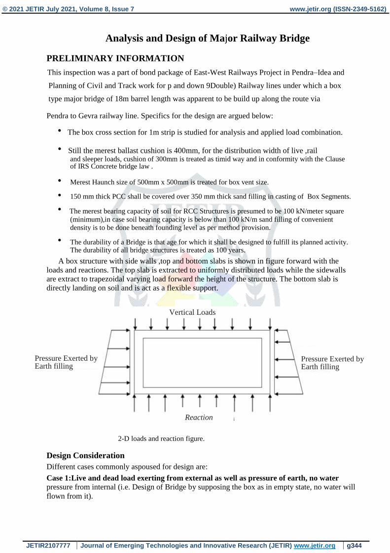
A box structure with side walls ,top and bottom slabs is shown in figure forward with the
loads and reactions. The top slab is extracted to uniformly distributed loads while the sidewalls are extract to trapezoidal varying load forward the height of the structure. The bottom slab is
directly landing on soil and is act as a flexible support.
Vertical Loads
Pressure Exerted by Earth filling
Pressure Exerted by Earth filling
Reaction
2-D loads and reaction figure.
Design Consideration
Different cases commonly aspoused for design are:
Case 1:Live and dead load exerting from external as well as pressure of earth, no water
pressure from internal (i.e. Design of Bridge by supposing the box as in empty state, no water will
flown from it).

© 2021 JETIR July 2021, Volume 8, Issue 7 www.jetir.org (ISSN-2349-5162)
JETIR2107777 Journal of Emerging Technologies and Innovative Research (JETIR) www.jetir.org g345
Figure 2 Components of box structure
sidewalls. Rump of 300 × 300 mm are given sob openings having punctured lines 2 Nos. of 150 mm
breadth to help water pass without any problem. Substantial grade of M 35 and Steel grade of Fe500
is received.
Cross section of cast in-situ box
Case 2:Live and dead load exerting from external as well as pressure of earth, while water
pressure exerting from internal (i.e. artful the by treating is half full).
Case 3: Live and dead load exerting from external as well as pressure of earth, while water
pressure exerting from intenal (i.e. artful the box by treating is full).
Note: General investigation for every one of the three cases were completed. In view of the benefits
of bowing second and shear compel it was discovered that case 1 creates the basic qualities. Consequently the plan was done physically and computationally just for case 1 as it is the absolute worst situation.
Geometry Of ROB 1 FL Box Bridge ;
Parts and Section of Box Bridge is displayed in Figures. It portrays the situation of rail level, sleepers, counter balance, development level and establishment level. A pad of 100 mm is given
pad of 100 mm is given when the arrangement level doesn't concur with the case high level. Side dividers
are exposed to earth filling and the base section is furnished with a 100 mm thick PPC concrete. It has
an unmistakable flat and vertical opening of 6 m and 3 m individually in 0.2 m soil fill. The has an
unmistakable level and vertical opening of 6 m and 3 m individually in 0.2 m soil fill. The and at

© 2021 JETIR July 2021, Volume 8, Issue 7 www.jetir.org (ISSN-2349-5162)
JETIR2107777 Journal of Emerging Technologies and Innovative Research (JETIR) www.jetir.org g346
Analysis and Design of Major Railway Bridge
Staad Sectional model of the container structure is displayed in Fig. 4. The viable level
width and vertical stature is 6.6 m and 3.6 m individually. The base piece is accepted to the laying
coordinating on soil and spring upholds are applied to it.
METHODOLOGY
1.Manual investigation of RCC box has been finished utilizing Moment Distribution Method (MDM).
2.Manual plan has been done utilizing working pressure technique (WSM).
3. Computational investigation has been finished utilizing Staad-Pro.
4. Computational plan for flexural conduct has been finished utilizing Ultimate cutoff State (ULS)
and break check has been finished utilizing Serviceability limit State (SLS).
Plan Of ROB 1FL Bridge

© 2021 JETIR July 2021, Volume 8, Issue 7 www.jetir.org (ISSN-2349-5162)
JETIR2107777 Journal of Emerging Technologies and Innovative Research (JETIR) www.jetir.org g347
followed by a few burden blends for SLS and ULS second and shear. above fiures
shows in like manner the varieties of B.M and S.F at top chunk, side divider and base
section for the absolute worst burden mix got utilizing Staad Pro. These B.M and S.F
esteems were utilized to plan the minor scaffold dependent on ULS and SLS rules.

© 2021 JETIR July 2021, Volume 8, Issue 7 www.jetir.org (ISSN-2349-5162)
JETIR2107777 Journal of Emerging Technologies and Innovative Research (JETIR) www.jetir.org g348
Bar Bending Scheduled
Note:-
All dimensions should be measured inner to inner .

© 2021 JETIR July 2021, Volume 8, Issue 7 www.jetir.org (ISSN-2349-5162)
JETIR2107777 Journal of Emerging Technologies and Innovative Research (JETIR) www.jetir.org g349

© 2021 JETIR July 2021, Volume 8, Issue 7 www.jetir.org (ISSN-2349-5162)
JETIR2107777 Journal of Emerging Technologies and Innovative Research (JETIR) www.jetir.org g350
DISCUSSION
Estimations were finished utilizing manual methodology and computational methodology and
Results were looked at in the table beneath above shown. Examination of manual and staad results
is displayed above. It is seen that outcomes acquire from Staad-Pro ace is a lot higher than that of
manual methodology. This is because of the way that Staad keeps a lot higher factor of security
than endorsed by the code to guarantee that the construction is protected. Divergence in
Bending Moment for Top section might be a result of various technique (WSM and LSM) received
for plan.

© 2021 JETIR July 2021, Volume 8, Issue 7 www.jetir.org (ISSN-2349-5162)
JETIR2107777 Journal of Emerging Technologies and Innovative Research (JETIR) www.jetir.org g351
Results
Moment Distribution Method (MDM) results:
The investigation was accomplished for every one of the three cases twisting second
and direct Shear esteems for Top Slab, Side Wall and Bottom Slab for all the three cases
as displayed previously. Nonetheless, the plan has been finished by Working Stress Method
(WSM). For case 1 just as it gives the basic (most extreme) upsides of the three cases
Additionally, the support subtleties for the basic condition have been portrayed in above pragraph.
The outcomes got from manual estimations were practically identical to the outcomes got
from computational estimations.
Commutation outcomes (STAAD-Pro Analysis) text
Examination of the crate type minor scaffold for void box condition with dead loads
and live loads on top and earth pressing factor and overcharges along the edge divider has been
finished utilizing dominate sheet and staad-professional . Burden cases were shaped dependent
on IRS-CBC codal arrangements followed by a few burden blends for SLS and ULS second
and shear. shows as needs be the varieties of B.M and S.F at top piece, side divider and base
chunk for the most noticeably terrible conceivable burden mix got utilizing Staad Pro.
These B.M and S.F esteems were utilized to plan the minor scaffold dependent on ULS and SLS rules.
Serviceability Limit State [SLS] condition
In this the primary individuals are to be checked for stresses in materials i.e., cement
and steel. Boundaries like break width, diversion, shrinkage and creep are needed to be
checked under SLS condition. In the current investigation, break width is SLS condition. In the
current investigation, break width is the characterizing boundary and the restricting worth of break was discovered to be 0.2 mm.
Ultimate Limit State [ULS] condition
In this the underlying individuals are to be checked for flexure, shear and twist.
In the present study twist was not appropriate, consequently basic bowing second and shear esteems were determined furthermore, plan has been done as needs be founded on ULS measures.
Note: Note: a definitive cutoff and administration limit state load factors are straightforwardly
applied in model in terms of burden mixes to get most exceedingly terrible anxieties.
The mixes considered are displayed above for the two SLS and ULS conditions.
Plan rundown
Rundown of Design Bending Moment and Shear Force is displayed above. Burden blend
from 50-56 is for Maximum B.M (SLS condition), load blend from 100-106 is for
greatest B.M (ULS condition) and burden blend from 200-206 is for most extreme S.F (ULS
condition). To ascertain lasting SLS B.M (Mg), all live loads were wound down in staad
supervisor and afterward basic B.M esteem was extricated from case 50-56. Live burden SLS B.M is determined by taking away perpetual SLS B.M (Mg) from Total SLS B.M (M). After basic values for each part has been acquired plan is done dependent on ULS and SLS standards. Support itemizing like bar width, bar separating, Reinforcement gave and least support required (in view of IRS CBC) is displayed above. The base support was 0.2 % of the space
of cement (Ac). The support gave was more than the base support prerequisite. Subsequently the support specifying was adequate and protected by the Ultimate Limit State measures.

© 2021 JETIR July 2021, Volume 8, Issue 7 www.jetir.org (ISSN-2349-5162)
JETIR2107777 Journal of Emerging Technologies and Innovative Research (JETIR) www.jetir.org g352
Note:
The bar number gave above aides in booking of support as displayed in
in this way by just appearance bar number in the support outline, subtleties like breadth given
and bar separating can be seen consequently lessening the intricacy of the support graph
Usefulness rules depended on break width estimations. The determined break width was
discovered to be inside the passable break width cutoff of 0.2 mm. Thus the plan was adequate
and protected by workableness Limit State measures The point by point support drawing of the
the container structure is displayed in support Planning has been finished utilizing bar number to
documentation and so forth to lessen the intricacy of the drawing. Bar measurement, dispersing
and connect (tie) can be effectively perceived from the bar number.
CONCLUSION
The primary target of this task was to consider the conduct of box type major railroad
connect when exposed to various blend of burdens as far as twisting second and Shear power
varieties. The plan was finished by utilizing Working Stress Method if there should be an
occurrence of Manual Approach and utilizing Ultimate Limit State strategy and serviceability
Limit State technique in the event of Computational Approach (Staad Pro).So from examination
and plan we closed:
1. The basic segments considered are the focal point of range of top and base chunks and the
backside and at the middle and hindquarters of the upward dividers since the greatest plan
powers create at these segments because of different blends of stacking designs.
2. The investigation shows that the greatest plan powers produced for the stacking condition
when the top chunk is exposed to the dead burden and live burden and sidewall is exposed
to earth pressing factor and overcharges, and when the course is unfilled.
3. The greatest negative second create at the waist of the top section for the condition that the
that the case is unfilled and the top lump passes on the dead weight and live weight.
4. The most extreme positive second create at the rump part of the top chunk for the condition
that the carton is unfilled and the top area passes on the dead weight and live weight.

© 2021 JETIR July 2021, Volume 8, Issue 7 www.jetir.org (ISSN-2349-5162)
JETIR2107777 Journal of Emerging Technologies and Innovative Research (JETIR) www.jetir.org g353
.
5. The most outrageous positive second make at the waist of the base piece for the situation
that the container is unfilled and the top segment passes on the dead weight and live weight.
6. The most extreme negative second create at the rump part of the base chunk for the condition
that the container is unfilled and the top segment passes on the dead weight and live weight.
7. The most extreme positive second create at the rump of vertical divider when the case
is vacant and when parallel pressing factor (Earth pressure, Live Load Surcharge and Dead
Load Surcharge) acts.
8. It was seen that Computational strategy (Staad- Pro) was significantly more skillful than
Moment Distribution Method (MDM) in term of proficiency of result and time utilization.
9. The component of an extension assumes an administering part for the association of different
burdens and there cases for the planning reason.
10. It is discovered that for planning any rail line connect applicable IRS codes were
to be carefully followed.
Reference:
1. S: 456-2000. Plain and reinforcement concrete. Code of practice. Bureau of Indian
Standards, New Delhi.
2. Bar Bending scheduled according to IS code-800:2007.
3. Bridge Drawing approved by RDSO.
4. Stad-Pro data used by IRS - Concrete Bridge Code 1997
5.IRC SP 054: Project Establishment Handbook for Bridge.
6.Design Manual DIMTS India Pvt. Ltd.
7. Sharif A.H. (2016), Study and Design of Railway Bridge and Corelation between
Staad-pro and Auto Cad Software and MDM Results, International Journal of
Logical Development and Research (IJSDR), 1(8), pp 1-7.
8. Paval B. (2016), Study of Multi-Cell Prestressed Concrete Box Bridge,
Overall Journal of Engineering Technology Science and Research IJETSR, 3(4), pp
106-113.
9. Chandrakant L.A. and Malgonda P.V. (2016), Bound Element Study of Box Culvert,
Global Journal of Advanced Technology in Engineering and Science IJATES, 2(6),
pp 93-102.