Design and Construction of Concrete Formwork
50
7-1 7 Design and Construction of Concrete Formwork David W. Johnston, P.E., Ph.D. * 7.1 Introduction ........................................................................7-2 7.2 Types of Formwork .............................................................7-5 Contact Surface Materials • Floor-Forming Systems • Column Forms • Wall Forms • Shoring • Bracing and Lacing • Other Forms and Components 7.3 Formwork Standards and Recommended Practices .......7-17 American Concrete Institute Recommendations • OSHA Standards • American National Standards Institute • Scaffolding, Shoring, and Forming Institute Guides and Rules • American Society of Civil Engineers Standards • Information from Formwork Suppliers • General Material Design Standards 7.4 Loads and Pressures on Formwork..................................7-23 Vertical Loads • Lateral Pressures of Concrete • Horizontal Loads 7.5 Formwork Design Criteria................................................7-27 ASD Adjustment Factors for Lumber Stresses • Load Duration Factor (C D ) • Moisture Factor (CM) • Size Factor (C F ) • Flat-Use Factor (C fu ) • Beam-Stability Factor (C L ) • Column-Stability Factor (C P ) • Bearing-Area Factor (C b ) • Repetitive-Use Factor (C r ) • Adjustment Factors for Plywood Stresses • Manufactured Wood Products • Safety Factors for Formwork Accessories 7.6 Formwork Design..............................................................7-35 Determination of Resultants from Loads • Fundamental Relations between Resultants and Stresses • Basis of Examples 7.7 Slab-Form Design Example ..............................................7-38 Sheathing Design • Joist Design • Stringer Design • Shore Design • Bracing Design Considerations 7.8 Wall-Form Design Example .............................................7-43 Sheathing Design • Stud Design • Wale Design • Tie Design • Bracing Design References .....................................................................................7-49 * Edward I. Weisiger Distinguished Professor in Construction Engineering and Management, North Carolina State Uni- versity, and Fellow of the American Concrete Institute and American Society of Civil Engineers; expert in the construction and performance of structures, formwork loadings and design, failure analysis, and bridge management systems. © 2008 by Taylor & Francis Group, LLC
Transcript of Design and Construction of Concrete Formwork

7-1
7Design and
Construction ofConcrete Formwork
David W. Johnston, P.E., Ph.D.*
7.1 Introduction ........................................................................7-27.2 Types of Formwork .............................................................7-5
Contact Surface Materials • Floor-Forming Systems • Column Forms • Wall Forms • Shoring • Bracing and Lacing • Other Forms and Components
7.3 Formwork Standards and Recommended Practices .......7-17American Concrete Institute Recommendations • OSHA Standards • American National Standards Institute • Scaffolding, Shoring, and Forming Institute Guides and Rules • American Society of Civil Engineers Standards • Information from Formwork Suppliers • General Material Design Standards
7.4 Loads and Pressures on Formwork..................................7-23Vertical Loads • Lateral Pressures of Concrete • Horizontal Loads
7.5 Formwork Design Criteria................................................7-27ASD Adjustment Factors for Lumber Stresses • Load Duration Factor (CD) • Moisture Factor (CM) • Size Factor (CF) • Flat-Use Factor (Cfu) • Beam-Stability Factor (CL) • Column-Stability Factor (CP) • Bearing-Area Factor (Cb) • Repetitive-Use Factor (Cr) • Adjustment Factors for Plywood Stresses • Manufactured Wood Products • Safety Factors for Formwork Accessories
7.6 Formwork Design..............................................................7-35Determination of Resultants from Loads • Fundamental Relations between Resultants and Stresses • Basis of Examples
7.7 Slab-Form Design Example..............................................7-38Sheathing Design • Joist Design • Stringer Design • Shore Design • Bracing Design Considerations
7.8 Wall-Form Design Example .............................................7-43Sheathing Design • Stud Design • Wale Design • Tie Design • Bracing Design
References .....................................................................................7-49
* Edward I. Weisiger Distinguished Professor in Construction Engineering and Management, North Carolina State Uni-versity, and Fellow of the American Concrete Institute and American Society of Civil Engineers; expert in the constructionand performance of structures, formwork loadings and design, failure analysis, and bridge management systems.
© 2008 by Taylor & Francis Group, LLC
7-2 Concrete Construction Engineering Handbook
7.1 Introduction
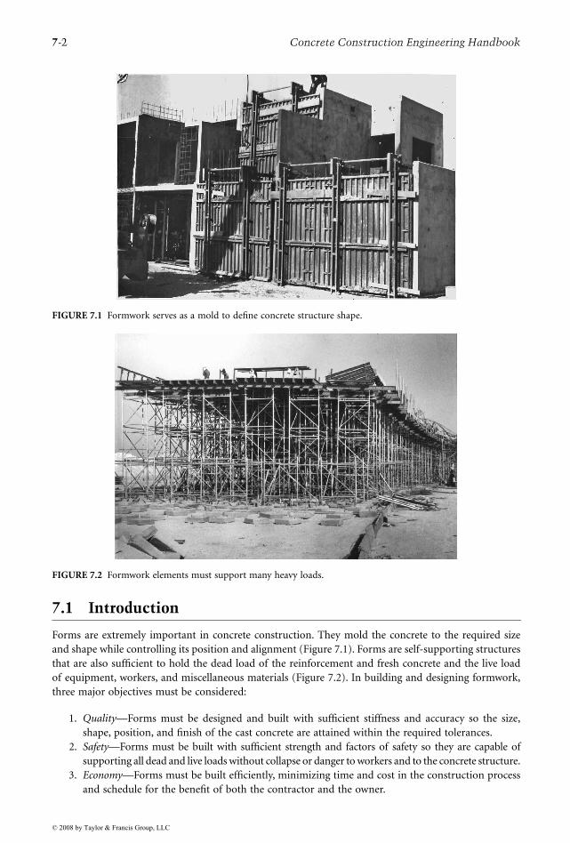
Forms are extremely important in concrete construction. They mold the concrete to the required sizeand shape while controlling its position and alignment (Figure 7.1). Forms are self-supporting structuresthat are also sufficient to hold the dead load of the reinforcement and fresh concrete and the live loadof equipment, workers, and miscellaneous materials (Figure 7.2). In building and designing formwork,three major objectives must be considered:
1. Quality—Forms must be designed and built with sufficient stiffness and accuracy so the size,shape, position, and finish of the cast concrete are attained within the required tolerances.
2. Safety—Forms must be built with sufficient strength and factors of safety so they are capable ofsupporting all dead and live loads without collapse or danger to workers and to the concrete structure.
3. Economy—Forms must be built efficiently, minimizing time and cost in the construction processand schedule for the benefit of both the contractor and the owner.
FIGURE 7.1 Formwork serves as a mold to define concrete structure shape.
FIGURE 7.2 Formwork elements must support many heavy loads.
© 2008 by Taylor & Francis Group, LLC

Design and Construction of Concrete Formwork 7-3
Economy is important because the costs of formwork often range from 35 to 60% or more of the totalcost of the concrete structure. Considering the impact of formwork on total cost, it is critical that thestructural engineer of the facility also design the facility structure for economy of forming, not just foreconomy of the materials in the finished structure.
Ideally, the builder will achieve maximum economy with no cost to either safety or specified quality.In designing formwork, the construction engineer can reduce costs by carefully considering the materialsand equipment to be used; the fabrication, erection, and stripping procedures; and the reuse of forms.However, economy measures that result in either formwork failure or poor-quality products that require(often expensive) modification are self-defeating.
Correctly designed formwork will ensure that the concrete maintains the desired size and shape byhaving the proper dimensions and being rigid enough to hold its shape under the stresses of the concrete.It must be stable and strong to keep large sections of concrete in alignment (Figure 7.3). Finally, formworkmust be substantially constructed so it can be reused and frequently handled while maintaining its shape.Formwork must remain in place until the concrete is strong enough to carry its own weight. In addition,the surface finish of the concrete is dependent on the contact material of the form.
The quality of the formwork itself has a direct impact on safety, accidents, and failures. A floorformwork system filled with wet concrete has its weight at the top and is not inherently stable. As a result,one of the most frequent causes of failure is from effects that induce lateral forces or displacement ofsupporting elements; therefore, inadequate cross-bracing or horizontal bracing is one of the most fre-quently involved factors in formwork failure. Poor bracing can make a minor failure turn into a majordisaster, in what might be thought of as a domino effect or a progressive failure: A failure at one pointin the formwork that can become an extensive collapse through chain reaction. Vibration is one factorthat can trigger failure through inadequate bracing. Two other formwork problems are unstable soilunder mudsills and shoring that is not plumb. Formwork is stable if adequately braced and built so allloads are carried to solid ground through vertical and bracing members.
FIGURE 7.3 Large and complex placements require substantial formwork.
© 2008 by Taylor & Francis Group, LLC

7-4 Concrete Construction Engineering Handbook
Regardless of the quality of the formwork, premature removal of the forms or shores, often out of awish for economy, can result in collapse or sagging. Sagging, while not an immediate problem, can leadto hairline cracks and extensive maintenance problems. Careless reshoring, often involving inadequatesize, spacing, or attachment, can also cause damage or collapse. Specific related standards (e.g., OSHA,ACI, ASCE) for formwork are discussed in Section 7.3.
In addition to optimizing material in the form design process, there are three major factors to beconsidered when planning forms that are cost effective:
• Designing and planning for maximum reuse• Economical form assembly• Efficient setting and stripping
Each factor must be balanced with the other two to determine the most efficient form design.In planning for maximum reuse, the specifications, rate of concrete strength gain, and local code
requirements regarding stripping must be taken into account. The sooner a form can be stripped safely,the more practical it is to reschedule many reuses. In addition, for a minimum of cost, the least numberof forms required for a smooth work schedule should be built. For example, the formwork on the outsideof a spandrel beam can be stripped sooner than the formwork on the bottom; hence, fewer side formsthan bottom forms must be built because they can be reused more frequently. It is also important toconsider the labor involved in reuse; for example, does the form need to be disassembled and rebuilt?To create a plan for reuse, the construction engineer needs to make a detailed study of the work flowand construction sequence to determine the practical number of reuses that will result in smooth andefficient construction with the lowest total cost (Figure 7.4). When comparing designs, the constructionengineer should calculate the ratio of total contact area of the formed concrete structure to the first-useform contact area for various alternatives, which is a general indication of overall reuse efficiency.
FIGURE 7.4 Planning is required to achieve maximum overall construction efficiency.
© 2008 by Taylor & Francis Group, LLC

Design and Construction of Concrete Formwork 7-5
Several considerations are involved in determining an economical form construction, such as:
• Cost and feasibility of adapting materials on hand vs. cost of buying or renting new materials• Cost of a higher grade of material vs. cost of lower grade of material plus labor to improve for
required quality and use• Selection of more expensive materials that provide greater durability and capability for reuse vs.
less expensive materials that have a shorter use-life• Building on-site vs. building in a central shop and shipping to site (this depends on the site itself
and space available, the size of project, the distance of shipping, etc.)
An estimate of the cost of constructing a particular job-built form can be obtained by determining thequantity of wood materials required to make 1 square foot of contact area, while allowing for waste andrejection of some wood, and multiplying by the unit prices of lumber involved. This provides thecontractor with an estimate of lumber costs for 1 square foot of contact area. In addition to lumber, thecosts for labor, hardware, miscellaneous materials, handling, and clean-up must also be evaluated. Theconstruction engineer should also consider the possibility of using prefabricated forms, either rented orpurchased. The advantages of using rented prefabricated forms are reduced risk, no investment cost, andtransfer of some management responsibility to the formwork supplier or subcontractor.
The last major factor, efficient setting and stripping practices, has a direct impact on the two alreadydiscussed. Reuse of a form is only fully efficient if the form can be stripped and rebuilt without too muchlabor time or damage to the form. The estimate for constructing a form must take into account theworker hours required to erect and dismantle the form during each reuse. When calculating time andcost for setting and stripping forms, the contractor should allow for delays from weather, equipmentproblems, etc., as well as cleaning and other miscellaneous expenses.
In addition to the above elements of cost, planning of formwork operations should consider the overallflow of operations, including the following:
• Crew efficiency—Providing a reasonable schedule creates a smooth daily repetition of the sameoperation so the workers can be familiar with their tasks and thus perform efficiently.
• Concreting—The ease and speed of pouring the concrete are directly related to the choice of designand the construction schedule.
• Bar setting and other trades (mechanical, electrical, piping)—Schedules of these activities must becoordinated with the concreting schedule so that all groups can work efficiently.
• Cranes and hoists—Plan to use appropriate cranes at times when they are not needed for otherfunctions and reduce idle time.
7.2 Types of Formwork
Formwork components can be assembled in a wide variety of systems for casting many structural shapes.The terms formwork and falsework are often used in combination. Formwork is the total system ofsupport for freshly placed concrete and includes the sheathing that is in contact with the concrete as wellas all supporting members, hardware, and necessary bracing. Falsework is a temporary structure erectedto support work in the process of construction. Falsework may be the temporary support for steel bridgegirders, for precast concrete elements to be post-tensioned together, or for many other applications.When this term is used in relation to formwork, the forms are often considered to be the horizontalsystem of elements directly under heavier concrete placements, such as cast-in-place bridges (Figure 7.2),and the falsework includes the temporary girders, shores or vertical posts, and lateral bracing. Forms caneither be job built or prefabricated. Job-built forms, frequently of wood (Figure 7.5), are most frequentlyselected where the shape does not conform to the constraints of commercial systems or where theeconomics are viable. Prefabricated forms can be purchased, rented, or rented with an option to buy.They are usually constructed substantially for the purpose of frequent reuse. These forms can either beready made or custom made (Figure 7.6). The latter is designed for specialized use, usually on a singlejob, but is often reused multiple times on that project.
© 2008 by Taylor & Francis Group, LLC

7-6 Concrete Construction Engineering Handbook
7.2.1 Contact Surface Materials
The material serving as the contact face of forms is known as sheathing and sometimes is referred to aslagging or sheeting in specialty applications. Plywood is frequently used for sheathing, but some formsuse steel sheet metal, steel plate, fiber-reinforced plastic, paperboard, wood boards, or other materials.
FIGURE 7.5 Wood column form.
FIGURE 7.6 Custom-made steel form with integrated access platforms.
© 2008 by Taylor & Francis Group, LLC

Design and Construction of Concrete Formwork 7-7
A primary characteristic in selection of the sheathing type and grade is the quality of surface requiredby the specification. For some applications, steel or high-density overlay plywood may be needed. Inother cases where a decorative surface is required, the sheathing may be specially treated (wire brushingto expose wood grain, addition of rustication strips, etc.) or fitted with a commercial plastic linerimprinted or shaped to provide a specified design (Figure 7.7). Permanent forms are any form thatremains in place after the concrete has developed its design strength. The form may or may not becomean integral part of the structure. Metal deck forms, the most prevalent permanent form, are made of aribbed or corrugated steel sheet, usually galvanized to reduce the potential for future rust staining, andare secured to the structure with clips or by welding. The diaphragm created by the attached deck mayalso contribute to the lateral stability of the supporting members during concrete placement. Metal deckforms are used in floor and roof slabs cast over steel joists or beams, in bridge decks (Figure 7.8), andover pipe trenches and other inaccessible locations where removing wood forms is impractical. Precastconcrete deck forms are often used in combination with prestressed concrete bridge girders. Sometimes
FIGURE 7.7 Plastic form liner used to create rough ribbed pattern.
FIGURE 7.8 Stay-in-place corrugated galvanized metal deck for bridge-slab form.
© 2008 by Taylor & Francis Group, LLC

7-8 Concrete Construction Engineering Handbook
the deck forms must be temporarily shored at intermediate points to support the loads applied duringconstruction; however, deck forms of adequate section profile can often be selected to span between thepermanent structural members and safely support the weights of reinforcement, fresh concrete, andconstruction live loads. In the latter case, the added cost of the stronger section is often offset by savingsin shoring materials and labor.
7.2.2 Floor-Forming Systems
Floor-forming systems vary somewhat with the configuration of the concrete floor system being cast.Figure 7.9 illustrates the basic wood member arrangements for flat-plate floors, most areas of flat slabs,and the slab areas of slab and beam floors. The terms used to describe the members are the same insystems assembled from steel or aluminum members. The joist is a horizontal structural member sup-porting the deck-form sheathing and usually rests on stringers or ledgers. Stringers are horizontal struc-tural members usually (in slab-forming) supporting joists and resting on vertical supports such as shores.
FIGURE 7.9 Typical elevated flat-slab formwork elements. (From Hurd, M.K., Formwork for Concrete, 7th ed., SP-4,American Concrete Institute, Farmington Hills, MI, 2005.)
Sheathing
Joist
Stringer
Bracing
recommended
throughout
system
Shores
Wedges
Mudsill
Use positiveconnection
betweenshores and
stringers
© 2008 by Taylor & Francis Group, LLC

Design and Construction of Concrete Formwork 7-9
In one-way (pan joist) and two-way (waffle) joist construction, a similar layout is usually adopted.Pans and domes (Figure 7.10) are used in concrete joist construction, which is a cast-in-place floor systemwith a thin slab integral with regularly spaced joists that span to beams and columns. In some cases, thepans or domes are placed on the plywood sheathing; in other cases, the pan or dome edges are supportedon wide joists, and the sheathing is omitted. Pans are prefabricated form units, usually steel or fiberglass,used to form single-direction joists. Domes, also usually made of steel or fiberglass, are square pan formsused in two-way, or waffle, concrete joist construction.
Steel and aluminum joists and stringers are usually flanged shapes. Some aluminum extrusions havespecial configurations allowing easy connection and incorporating a top channel for a wood nailer.Commercial steel sections fabricated specifically for formwork systems also incorporate connectionfeatures. Horizontal shoring is formed by adjustable beams, trusses, or combinations of the two thatsupport formwork over clear spans and eliminate numerous vertical supports. Metal or timber supportbeams are used for small spans. Telescoping shores, steel lattice, plate, or box members are used to supportforms in spans of 6 to 30 feet. Heavy-duty horizontal shores (for example, trusses supporting flying-formpanels) can span up to 80 feet. The disadvantage of using horizontal shoring is the potential need forspecial bearing plates to support the high end load on each individual shore.
Flying forms, or table forms, are large crane-handled sections of floor formwork (frequently includingsupporting truss, beam, or scaffolding frames) that are completely unitized. Such forms can be loweredfor clearance under joists or beams, rolled out the face of the building bay, picked by a crane, and resetat the next floor level. By having a large movable unit, the costs of stripping and reassembly are reduced,particularly when a crane is available on site.
7.2.3 Column Forms
Column-form materials tend to vary with the column shape. Wood or steel is often used with square orrectangular columns (Figure 7.11). Round column forms (Figure 7.12), more typically premanufacturedin a range of standard diameters, are available in steel, paperboard, and fiber-reinforced plastic. Squareand rectangular forms are composed of short-span bending elements contained by external ties or clamps.Round column forms are more structurally efficient because the internal concrete pressures can be resistedby a hoop membrane tension in the form skin with little or no bending induced. Round, single-pieceglass-fiber-reinforced plastic tubes with a single joint can be removed from the column without cutting.They are held together with either bolts or clamps. Round paperboard tubes are single-use forms that arestripped by unwrapping and then discarded. They can be cut to the exact length needed, and sections ofthe tube can be adapted to making partial column sections (e.g., half-round, quarter-round). Steel columnforms have built-in bracing for short heights so the only external bracing required serves to keep thecolumn plumb and for taller columns. Both half-round and rectangular panel units are available in varioussection heights that can be connected vertically to form tall columns. Round steel forms are generallyused for larger columns and bridge piers and come in diameters ranging from about 14 inches to 10 feet.
FIGURE 7.10 Fiber-reinforced plastic pan and dome molds for floor formwork.
© 2008 by Taylor & Francis Group, LLC

7-10 Concrete Construction Engineering Handbook
7.2.4 Wall Forms
Wall forms principally resist the lateral pressures generated by fresh concrete as a liquid or semi-liquidmaterial. The pressures can be quite large, certainly many times the magnitude of live loads on permanentfloors. Thus, wall form design often involves closely spaced and well-supported members, as shown inFigure 7.13. As mentioned, the contact surface of the wall form is referred to as sheathing. Studs are
FIGURE 7.11 Modular steel form for rectangular columns.
FIGURE 7.12 Steel round-column form with access scaffolding in preparation.
© 2008 by Taylor & Francis Group, LLC

Design and Construction of Concrete Formwork 7-11
vertical supporting members to which sheathing is attached. Wales are long horizontal members (usuallydouble) used to support the studs. The studs and wales are often wood, steel, or aluminum beam-likeelements. Commercial form suppliers are innovative in devising elements as well as hardware for con-nections. The wall form members are sometimes oriented with the stud members placed horizontalrather than vertical, and the wales are run vertical.
The wales are in turn supported on washer plates or other bearing devices attached to form ties. Aconcrete form tie is a tensile unit connecting opposite sides of the form and providing a link forequilibrium. Form ties are usually steel, although some fiber-reinforced plastic ties are also available. Theties come in a wide range of types (Figure 7.14) and tension working capacities rated by the manufacturer.Snap ties, loop ties, and flat ties are single-use ties, usually of relatively low capacity (1500 to 3200 lb)that are twisted and snapped off a specified distance back from the concrete surface. Coil ties, she bolts,and he bolts are examples of ties where some parts are left embedded within the cast wall and some partscan be reused. The taper tie, a tapered rod threaded on each end, is completely removed and reused. Thetension capacity of heavy ties can range upward to over 60,000 lb. Some of the ties have built-in provisionsfor spacing the forms a definite distance apart; this is particularly true of single-use ties if this feature isordered. An alternative means of maintaining the correct inside distance is by means of a spreader, astrut (usually of wood) inserted inside the forms that can be retrieved with an attached rope or wirewhen the concrete placement reaches that level.
Strong-backs, frames attached to the back of a form or additional vertical wales placed outsidehorizontal wales, are sometimes added for strength, to improve alignment, or to assemble a ganged form.Gang forms (Figure 7.15) are prefabricated panels joined to make a much larger unit for convenience inerection, stripping, and reuse; they are usually braced with wales, strong-backs, or special lifting hardware.Such units require the use of a crane for stripping and resetting.
Panel forms, sections of form sheathing constructed from boards, plywood, metal, etc. that can beerected and stripped as units, are primarily used in wall construction. They may be adapted for use as slabor column forms. The four basic types of panel forms are unframed plywood, plywood in a metal frame(Figure 7.16), all-metal, and heavier steel frame. The first two are most frequently used for general light
FIGURE 7.13 Typical wall form components with alternate sheathing materials illustrated. (From Hurd, M.K.,Formwork for Concrete, 7th ed., SP-4, American Concrete Institute, Farmington Hills, MI, 2005.)
Board sheathing
Plywood sheathing
Brace to solid
construction
Studs
Double wales
Sill or plate
Sill or plate
Wood spreader
Ties
© 2008 by Taylor & Francis Group, LLC

7-12 Concrete Construction Engineering Handbook
construction and erecting walls with heights ranging from 2 to 24 feet. Both are sometimes backed bysteel braces. All-metal panel forms can be made of either steel or aluminum. The heavier steel frame panelforms are faced with either wood or plywood and are used for projects involving large pressures or loads.
Slip forms are forms that move, usually continuously, during placing of the concrete. Movement maybe either horizontal or vertical. Slip-forming is like an extrusion process, with the forms acting as movingdies to shape the concrete. In wall forming, the slip form is usually moved vertically at a rate of 6 to 12inches per hour. This method can be economical when constructing concrete cores of tall buildings, tallconcrete stacks, and concrete towers.
FIGURE 7.14 Examples of form ties. (From Hurd, M.K., Formwork for Concrete, 7th ed., SP-4, American ConcreteInstitute, Farmington Hills, MI, 2005.)
Flat Tie
Loop Tie
Snap Tie with Spreader Washers
Fiberglass Tie
Taper Tie
Threaded Bar with Unattached Sleeve
She-Bolt Tie
Two-Strut Coil Tie with Cones
Inte
rnal
ly
Dis
con
ne
ctin
g T
ies
On
e–
Pie
ce T
ies
Secures and spaces prefabricated modular forms
Notched for a 1-in. breakback
Crimp is anti-turn feature
Safe Loads: 2250 and 3000 lb
Used to secure and space modular panel forms
Available in several configurations
Notched for breakback
Safe Loads 1500, 2250, and 3000 lb
Used for job-built forms, lighter construction
May have cone spreader and waterseal washer
Notched for 1-in. breakback
Safe Loads: 2250 and 3350 lb
Long lengths supplied for cutting as desired on the job
Custom colors available
Cut off flush with surface of hardened concrete
Safe Loads: 3000, 7500, and 25,000 lb
Used where specs require or permit complete
removal of tie from concrete
Tie is reusable
Safe Loads: 7500 to 50,000 lb
Heavy duty, with reusable end bolts
No internal spreader, but external spreader
bracket available
Safe Loads: 4900 to 64,000 lb
Up to 155,000 in High-Strength Steel
Designed for medium to heavy construction
With or without cone spreaders
Bolts reusable
Safe Loads: Two-strut, 3000 to 13,500 lb;
Four-strut, 9000 to 27,000 lb
Safe Loads: 10,000 to 32,500 lb
Standard 20-ft lengths cut to meet project requirements
Double nuts may be needed for higher load capacities
Bar is reusable
© 2008 by Taylor & Francis Group, LLC

Design and Construction of Concrete Formwork 7-13
Climbing forms, or jump forms, are forms that are raised vertically for succeeding lifts of concrete ina given structure, usually supported by anchors embedded in the previous lift. The form is moved onlyafter an entire lift is placed and (partially) hardened; this should not be confused with a slip form thatmoves during placement of the concrete. Support of the climbing form is usually provided by anchorscast in the previous placements. It is critical that the concrete strength gain at the anchors be sufficientat each stage of the operation to resist the imposed loads.
FIGURE 7.15 Ganged forms allow movement by crane and reduce re-erection costs.
FIGURE 7.16 Steel-framed plywood panel system with integrated loop-tie anchors.
© 2008 by Taylor & Francis Group, LLC

7-14 Concrete Construction Engineering Handbook
Although the use of proper support chairs for reinforcement is routinely required in horizontalconstruction, similar elements are sometimes neglected in wall and column forms. Side form spacers aredevices similar to chairs that can be used to advantage in wall and column forms to attain correct coverfor the reinforcement.
7.2.5 Shoring
Shores are vertical or inclined column-like compression supports for forms. Shoring systems may bemade of wood or metal posts, scaffold-type frames, or various patented members. Scaffolding is anelevated platform to support workmen, tools, and materials. In concrete work, heavy-duty scaffolding isoften adapted to double as shoring. The simplest type of vertical shore is a 4 × 4 or 6 × 6 piece of lumberwith special hardware attached to the top to facilitate joining to the stringers with a minimum of nailing.Metal shore-jack fittings may be placed at the lower end of the shore to allow some adjustment for exactheight. Various manufacturers sell all-metal adjustable shores, also known as jack shores or simply asjacks, in a number of designs. They are usually available in adjustable heights from 6 to 16 ft and cancarry working loads ranging from 2500 to 9000 lb with a safety factor of 2.5, depending on the type andthe length of the shore. A third type of vertical support is a device that attaches to a column or bearingwall of the structure. Components of this kind of shore include friction collars and shore brackets thatare attached to the support with through bolts or heavy embedded anchors. These attached supports areparticularly useful in supporting slab-forming systems.
Basic scaffold-type shoring is made from tubular steel frames. End frames are assembled with diagonalbracing, locking connections, and adjustable bases to create a shoring tower. These may have flat topplates, U-heads, or other upper members for attaching to supported forms. Most scaffold-type shoringhas a safe working load between 4000 and 25,000 lb per leg, depending on the height, bracing, andconstruction of the tower (Figure 7.17). Ultra-high-load shoring frames can support up to 100,000 lb ofload per leg. Scaffold-type shoring can also be made of tubular aluminum, which has the advantage ofbeing more lightweight than a similar steel frame.
In multistory concrete building construction (Figure 7.4), a process called shoring and reshoring isused (ACI Committee 347, 2005). The weight of the fresh concrete, reinforcing, forms, and constructionlive load for an individual floor usually exceeds the design live-load capacity of the floor below. Further-more, that floor has not gained full 28-day strength, as floors are often cast at intervals of 4 to 14 days.By interconnecting several floors with shores and reshores, the loads at the top can be distributed overseveral floors. When this construction process is engineered and controlled properly, the time-varyingloads on all elements (floors, forms, shores, and reshores) are safely within their time-varying strengths.One or more sets of floor forms with shores may be used. After the forms and shores are strippedcompletely from the lowest form-supported floor, that floor and the cast floors above deflect and mustshare the equivalent of the support that has been removed. Reshores are then placed under the strippedfloor. Reshores are shores placed snugly under a concrete floor so future loads imposed from constructionat the highest level can be shared over sufficient floors to carry the dead and live loads safely.
In some multistory construction, this process is varied slightly. Backshores are shores placed snuglyunder a concrete slab or structural member after the original forms and shores have been removed froma small area without allowing the slab or member to deflect or support its own weight or existingconstruction loads from above. Preshores are added shores placed snugly under selected panels of a deck-forming system before any primary (original) shores are removed. Preshores and the panels they supportremain in place until the remainder of the bay has been stripped and backshored, a small area at a time.
Shoring systems produced by some manufacturers include a drophead mechanism (Figure 7.18). Thesystems include panels, beams, and a shore with a top plate that is in direct contact with the concreteslab underside. When the drophead mechanism is released, the beams and panels can be lowered andremoved while the shore stays in place. This allows rapid reuse of the panels and beams while the shorecontinues to support the early-age, low-strength slab. Overall, this approach allows rapid reuse of com-ponents, increasing speed of construction and reducing forming materials needed. Keeping the shores
© 2008 by Taylor & Francis Group, LLC

Design and Construction of Concrete Formwork 7-15
in place longer under the most recently placed slab also increases safety. After appropriate slab strengthgain to support the slab self-weight and construction loads, the slab is activated by releasing the shoresand then resnugging them to act as reshores.
FIGURE 7.17 Shoring towers used for bridge falsework.
FIGURE 7.18 Drop-head shore allowing removal of panels and beams. (Figure courtesy of MEVA Formwork Systems,Haiterbach, Germany.)
© 2008 by Taylor & Francis Group, LLC

7-16 Concrete Construction Engineering Handbook
Centering is a specialized temporary vertical support used in construction of arches, shells, and spacestructures where the entire temporary support is lowered (struck or decentered) as a unit to avoidintroduction of injurious stresses in any part of the structure. Shores that are supported on the groundmust have a temporary footing (termed, in formwork, a mudsill) that is of adequate strength and size(Figure 7.19). The mudsill may be a plank, wood grillage, or precast pad, depending on the loads andground conditions.
7.2.6 Bracing and Lacing
A brace is any structural member used to support another, always designed for compression loads andsometimes for tension under special load conditions. In formwork, diagonal bracing is a supplementary(not horizontal or vertical) member designed to resist lateral load. Form braces are frequently made ofwood or steel. Commercial steel pipe braces in various diameters and wall thicknesses and load-ratedfor adjustable lengths are popular. Buckling strength of braces is always a primary design consideration.Horizontal lacing, horizontal members attached to shores or braces to reduce their unsupported length,can thus increase the available load capacity. Both bracing and lacing must be adequately connected ateach end. This can be accomplished with bolts, nails, and a variety of commercial devices, depending onthe materials involved. When attaching braces to the ground, a buried or above-ground concrete massknown as a deadman is sometimes used (Figure 7.20).
7.2.7 Other Forms and Components
The above represents only a brief summary of some of the most typical form elements. Many otherconfigurations must be considered in many jobs. Beam forms are somewhat like short wall forms in thatlateral pressures must be resisted; however, they also involve concentrations of vertical load, requiringstrong bottom forms and more shoring. The casting of footings sometimes requires forming where theconcrete cannot be cast against vertical earth sides. This forming often must be braced from the outsideto hold the lateral pressure of the earth if the width of the foundation is large. Supplementary formingelements such as templates are often incorporated in foundation forms to precisely locate anchor boltsand dowels (Figure 7.21). Where concrete elements must be subdivided into two or more placementsections, a form bulkhead is usually placed, either as a construction joint or as an end closure. Thebulkhead, although involving short spans, must be carefully designed and connected as it must resist thesame pressure magnitudes as the faces of the form.
FIGURE 7.19 Precast concrete mudsills distribute bridge falsework load to soil.
© 2008 by Taylor & Francis Group, LLC

Design and Construction of Concrete Formwork 7-17
Forms may also incorporate a host of other features. Chamfer strips are triangular or curved insertsplaced in the inside corner of a form to produce a rounded or beveled corner. These are often specifiedin rectangular columns and at outside corners of walls. Cleanouts are openings sometimes provided atthe bottom of wall or column forms for removal of refuse before the concrete is placed to ensure a goodconstruction joint. There must be a means of closing and supporting the cleanout door to resist concretepressure. Wrecking strips are small pieces or panels fitted into a formwork assembly in such a way thatthey can be easily removed ahead of the main panels or sections, making it easier to strip the major formcomponents. Various references, such as Hurd (2005) and form-supplier catalogs, provide numerousillustrations of formwork details.
7.3 Formwork Standards and Recommended Practices
Ultimately, formwork safety is dependent on the system in place on individual projects to ensureproper and safe design, fabrication, handling, erection, inspection, monitoring, and stripping of theforms and supports (Figure 7.22). As noted earlier, formwork materials and labor are roughly equalin cost to the concrete and reinforcing materials and placing labor. The loads supported by formwork
FIGURE 7.20 Formwork brace anchored to buried concrete mass.
FIGURE 7.21 Plywood templates secure dowels or anchor bolts at correct position.
© 2008 by Taylor & Francis Group, LLC

7-18 Concrete Construction Engineering Handbook
(say, for an individual floor) are usually similar in magnitude to the loads supported by the finishedstructure and are sometimes much greater. Thus, it is justifiable for the design and planning offormwork to require the significant time of a professional, just as is required for design of the structureof the facility being built. Savings can accrue from a well planned and designed system. This sectionsummarizes some of the resources available to the construction engineer to guide the planning anddesign of formwork. Most of the resources are in the form of guides or recommended practices. Exceptfor some provisions of OSHA, there has previously been no uniformly mandated standard in theUnited States for design of temporary structures such as formwork; however, this is in the process ofchange, as is noted in the following sections. As in all engineering work, the construction engineershould seek the most recent edition of the following resources. Most standards are updated or recon-firmed on a cycle of 6 years or less.
7.3.1 American Concrete Institute Recommendations
Prior to about 1958, formwork was designed based on only limited data and guidance for loads. At thattime, recommendations for loads and pressures for the design of formwork became available from theAmerican Concrete Institute (ACI). These recommendations have evolved over the years and are availablein three often-consulted and periodically updated ACI publications:
• Guide to Formwork for Concrete, ACI 347-04 (ACI Committee 347, 2004)• Formwork for Concrete, 7th ed., ACI SP-4 (Hurd, 2005)• Guide for Shoring and Reshoring of Multistory Concrete Buildings, ACI 347.2R (ACI Committee
347, 2005)
The first provides the recommended practice for design and construction of formwork, including rec-ommendations for loads and pressures. The second is a manual that extensively describes systems andprovides design procedures, design aids, and examples. The third provides methods for determiningshore, reshore, and early-age slab loads during multistory building construction. ACI also publishes,through its journals and other monographs, numerous articles on concrete formwork as well as guidesfor craftspersons involved in formwork fabrication and erection. ACI Committee 347 recommendationsfor loads and pressures to be applied in the design of formwork are discussed more thoroughly in Section7.4 of this chapter.
FIGURE 7.22 Guardrails and rated, well-maintained access ladders are components of a safety system.
© 2008 by Taylor & Francis Group, LLC

Design and Construction of Concrete Formwork 7-19
7.3.2 OSHA Standards
By the early 1970s, legislation to establish the Occupational Health and Safety Administration (OSHA)began to have an impact on formwork. OSHA expectations not only include an adequate temporarystructure but also emphasize components for worker fall protection (Figure 7.23 and Figure 7.24) andprocedures for safe handling and erection of formwork. Some states have their own requirements thatare different from, but cannot be less restrictive than, the federal requirements. Sections of the federalOSHA Occupational Safety and Health Standards for the Construction Industry (29 CFR, Part 1926)particularly affecting formwork planning, design, and execution includes the following requirements:
• Subpart L—Scaffolding• Subpart M—Fall Protection• Subpart Q—Concrete and Masonry Construction
FIGURE 7.23 Fall-protection nets.
FIGURE 7.24 Work platform being installed on tall wall form.
© 2008 by Taylor & Francis Group, LLC

7-20 Concrete Construction Engineering Handbook
Subpart Q contains sections on scope, application, and definitions; general requirements; equipment andtools; cast-in-place concrete; precast concrete; lift-slab operations; and masonry construction. Of primaryinterest here is the following section on cast-in-place concrete:
§ 1926.703 Requirements for cast-in-place concrete.
(a) General requirements for formwork.
(1) Formwork shall be designed, fabricated, erected, supported, braced, and maintained so that itwill be capable of supporting without failure all vertical loads that may reasonably be anticipatedto be applied to the formwork. Formwork which is designed, fabricated, erected, supported, braced,and maintained in conformance with the Appendix to this section will be deemed to meet therequirements of this paragraph.
(2) Drawings or plans, including all revisions, for the jack layout, formwork (including shoringequipment), working decks, and scaffolds, shall be available at the jobsite.
(b) Shoring and reshoring.
(1) All shoring equipment (including equipment used in reshoring operations) shall be inspectedprior to erection to determine that the equipment meets the requirements specified in the formworkdrawings.
(2) Shoring equipment found to be damaged such that its strength is reduced to less than thatrequired by § 1926.703(a)(1) shall not be used for shoring.
(3) Erected shoring equipment shall be inspected immediately prior to, during, and immediatelyafter concrete placement.
(4) Shoring equipment that is found to be damaged or weakened after erection, such that its strengthis reduced to less than that required by § 1926.703(a)(1), shall be immediately reinforced.
(5) The sills for shoring shall be sound, rigid, and capable of carrying the maximum intended load.
(6) All base plates, shore heads, extension devices, and adjustment screws shall be in firm contact,and secured when necessary, with the foundation and the form.
(7) Eccentric loads on shore heads and similar members shall be prohibited unless these membershave been designed for such loading.
(8) Whenever single post shores are used one on top of another (tiered), the employer shall complywith the following specific requirements in addition to the general requirements for formwork:
(i) The design of the shoring shall be prepared by a qualified designer and the erected shoringshall be inspected by an engineer qualified in structural design.
(ii) The single post shores shall be vertically aligned.
(iii) The single post shores shall be spliced to prevent misalignment.
(iv) The single post shores shall be adequately braced in two mutually perpendicular directionsat the splice level. Each tier shall also be diagonally braced in the same two directions.
(9) Adjustment of single post shores to raise formwork shall not be made after the placement ofconcrete.
(10) Reshoring shall be erected, as the original forms and shores are removed, whenever the concreteis required to support loads in excess of its capacity.
(c) Vertical slip forms.
(1) The steel rods or pipes on which jacks climb or by which the forms are lifted shall be
(i) Specifically designed for that purpose; and
(ii) Adequately braced where not encased in concrete.
© 2008 by Taylor & Francis Group, LLC

Design and Construction of Concrete Formwork 7-21
(2) Forms shall be designed to prevent excessive distortion of the structure during the jackingoperation.
(3) All vertical slip forms shall be provided with scaffolds or work platforms where employees arerequired to work or pass.
(4) Jacks and vertical supports shall be positioned in such a manner that the loads do not exceedthe rated capacity of the jacks.
(5) The jacks or other lifting devices shall be provided with mechanical dogs or other automaticholding devices to support the slip forms whenever failure of the power supply or lifting mechanismoccurs.
(6) The form structure shall be maintained within all design tolerances specified for plumbnessduring the jacking operation.
(7) The predetermined safe rate of lift shall not be exceeded.
(d) Reinforcing steel.
(1) Reinforcing steel for walls, piers, columns, and similar vertical structures shall be adequatelysupported to prevent overturning and to prevent collapse.
(2) Employers shall take measures to prevent unrolled wire mesh from recoiling. Such measuresmay include, but are not limited to, securing each end of the roll or turning over the roll.
(e) Removal of formwork.
(1) Forms and shores (except those used for slabs on grade and slip forms) shall not be removeduntil the employer determines that the concrete has gained sufficient strength to support its weightand superimposed loads. Such determination shall be based on compliance with one of the following:
(i) The plans and specifications stipulate conditions for removal of forms and shores, andsuch conditions have been followed, or
(ii) The concrete has been properly tested with an appropriate ASTM standard test methoddesigned to indicate the concrete compressive strength, and the test results indicate that theconcrete has gained sufficient strength to support its weight and superimposed loads.
(2) Reshoring shall not be removed until the concrete being supported has attained adequatestrength to support its weight and all loads in place upon it.
APPENDIX TO § 1926.703(a)(1) General requirements for formwork. (This Appendix is non-mandatory.)
This appendix serves as a non-mandatory guideline to assist employers in complying with the formworkrequirements in §1926.703(a)(1). Formwork which has been designed, fabricated, erected, braced, sup-ported, and maintained in accordance with Sections 6 and 7 of the American National Standard forConstruction and Demolition Operations—Concrete and Masonry Work, ANSI A10.9-1983, shall bedeemed to be in compliance with the provision of § 1926.703(a)(1).
7.3.3 American National Standards Institute
The standard suggested in the above OSHA provisions as a means for achieving compliance is theAmerican National Standard for Construction and Demolition Operations—Concrete and MasonryWork—Safety Requirements, ANSI A10.9-1997(R2004). Section 6, on vertical shoring, has provisionsfor loads and design, field practices, removal, tubular welded frame shoring, tube and coupler towershoring, and single-post shores. Section 7, on formwork, has provisions for loads, formwork design,placing and removal of forms, vertical slip forms, flying-deck forms, and horizontal shoring beams. Mostof the load and design provisions refer to the ACI Committee 347 Guide to Formwork for Concrete as theprocedure to follow.
© 2008 by Taylor & Francis Group, LLC

7-22 Concrete Construction Engineering Handbook
7.3.4 Scaffolding, Shoring, and Forming Institute Guides and Rules
This industry-supported institute publishes many relevant guides, rules, and training aids related toformwork and its support systems. Examples include the following:
• Scaffold Code of Safe Practice• Safety Procedures for Vertical Formwork• Flying and Handling Concrete Formwork• The Difference Between Scaffolding and Shoring• Wind Loads and Shoring• Safe Practices for Erecting and Dismantling Frame Shoring• Horizontal Shoring Beam Safety Rules• Single Post Shore Safety Rules• Rolling Shore Bracket Safety Rules• Recommended Frame Shoring Erection Procedures• Flying Deck Form Safety Rules
7.3.5 American Society of Civil Engineers Standards
A committee of the American Society of Civil Engineers has developed ASCE 37-02 Design Loads onStructures during Construction, a standard for loads imposed on structures during construction, includingtemporary structures. The standard covers many topics, including loads for formwork, falsework, andshoring. The loads and pressures imposed by concrete, construction interval winds, and other sourcesare defined. For wind loadings, reference for analysis method is made to ASCE 7, but ASCE 37 defineswind velocity reductions reflecting the short period of exposure during construction. As with anyvoluntary consensus standard, it is available for groups to specify in individual contracts, or it could becited as the standard for use by government agencies in rule making. Although various guides and industrypractices have been available for many years for the design of formwork, this standard makes availablefor the first time in the United States a document that defines loads in mandatory language that can beincorporated in contracts, codes, and safety laws.
7.3.6 Information from Formwork Suppliers
Formwork suppliers, of course, publish literature defining their products and limitations for their use.Data sheets indicate the load ratings of products such as form ties, shores, braces, wales, etc. for referenceby form designers of job-built systems. In addition, many form manufacturers supply preengineeredformwork systems (Figure 7.25) under rental or purchase arrangements for individual projects or generaluse. Such systems will come with rules and limitations whose implementation is required by the con-tractor as part of the rental or sales agreement. It is critical that these requirements be implemented asthe normal procedures for use and for training workers involved with the formwork.
7.3.7 General Material Design Standards
Although they do not specifically address formwork, the same criteria used for the design of permanentstructures in any particular material should also be applied to the design of formwork once the loadsand safety factors appropriate for formwork have been determined. Most forms are made of wood, steel,or aluminum or some combination of these materials. The usual reference design standards for thesematerials are as follows:
• National Design Specification for Wood Construction, ASD/LRFD, ANSI/AF&PA NDS-2005, Amer-ican Forest & Paper Association, Washington, D.C., 2005
• Steel Construction Manual: Allowable Stress Design, 13th ed., American Institute of Steel Construc-tion, Chicago, 2005
© 2008 by Taylor & Francis Group, LLC

Design and Construction of Concrete Formwork 7-23
• Aluminum Design Manual, The Aluminum Association, Arlington, VA, 2005• Plywood Design Specification, APA—The Engineered Wood Association, Tacoma, WA, 1997
The use of allowable stress design (ASD) currently dominates in the design of formwork, but use of theload and resistance factor design (LRFD) method is expected to gradually increase. Addresses for manyof the above sources of standards and specifications are given following the references at the end of thischapter.
7.4 Loads and Pressures on Formwork
The possible loads acting on formwork are many. Vertical loads are usually associated with the dead loadof the placed concrete and formwork and the live load of workers and their equipment. Internal pressureson vertical formwork result from the liquid or semi-liquid behavior of the fresh concrete. External forcessuch as wind exert horizontal loads on the forms, requiring bracing systems for lateral form stability.
7.4.1 Vertical Loads
Vertical loads acting on formwork (Figure 7.26) include the self-weight of the forms, the placed rein-forcement, the weight of fresh concrete, the weight of the workers, and the weight of placing equipmentand tools. The dead load of the concrete is usually estimated at 145 to 150 lb/ft3, including an allowancefor normal amounts of reinforcement. In cases where the reinforcement appears to be heavy, the materialsshould be calculated separately to determine the actual unit weight. Adjustments are also made forlightweight concrete densities. An 8-in. normal weight slab thus imposes a dead load of 150 lb/ft3 × (8in./12 in./ft), or 100 psf, on horizontal formwork. ACI Committee 347 (2004) recommends that horizontalformwork be designed for a minimum vertical live load of 50 psf to allow for workers and their incidental
FIGURE 7.25 Preengineered wall form system.
© 2008 by Taylor & Francis Group, LLC

7-24 Concrete Construction Engineering Handbook
placing tools such as screeds, vibrators, and hoses. When motorized carts or buggies are used, a minimumlive load of 75 psf is recommended. Furthermore, it is recommended that the minimum combined totaldesign dead and live load should be no less than 100 psf, or 125 psf if motorized buggies are used.Formwork self-weight can be calculated from the unit weights and sizes of the components. The weightof the formwork is often much less than the dead load of the concrete and the construction live loads;thus, during design, an allowance is frequently made for the form components as a superimposed loadper square foot. Because forms often weigh 5 to 15 psf, an initial estimate is made in this range basedon experience and then is verified after the members are sized.
7.4.2 Lateral Pressures of Concrete
Vertical formwork, such as that for walls and columns, is subjected to internal lateral pressure from theaccumulated depth of concrete placed. In a placement, fresh concrete, at least near the top and sometimesat greater depths, behaves as a liquid during vibration and generates lateral pressures equal to the verticalliquid head. Although concrete is a granular material with internal friction, the fluidization of the concreteresulting from internal vibration at least temporarily creates a liquid state; however, many factors appearto contribute to the lateral pressures being less than a liquid head at depths below the controlled depthof vibration. If the vertical placement rate is slow, the concrete mass below may have time to beginstiffening. If the concrete is warm, this stiffening may begin earlier. Internal concrete granular friction,form friction, migration of pore water, and other factors may also reduce the resulting lateral pressures.Admixtures, different types of cements, cement substitutes, and construction practices also affect thelevel of lateral pressure.
Tests have indicated that the pressures often have a distribution, as indicated in Figure 7.27, startingas a liquid pressure near the top and reaching a maximum at some lower level. For simplicity, designpractice usually assumes that the maximum pressure is uniform at a conservative value. ACI Committee347 (2004) recommends that, unless certain conditions are met, calculation of the pressure magnitudevs. depth should be as a full liquid head:
p = wh (7.1)
where p is the lateral pressure of concrete (lb/ft2), w is the unit weight of fresh concrete (lb/ft3), and h isthe depth of fluid or plastic concrete from the top of the placement to the point of consideration in theform (ft).
FIGURE 7.26 Weights of concrete, reinforcing, and formwork contribute to dead load.
© 2008 by Taylor & Francis Group, LLC

Design and Construction of Concrete Formwork 7-25
ACI 347-04 further states, however, that for concrete having a slump no greater than 7 in. and placedwith normal internal vibration to a depth of 4 ft or less, the formwork may be designed for a lateralpressure as follows, where pmax is the maximum lateral pressure (psf), R is the rate of vertical placement(ft/hr), T is the temperature of concrete (°F), CW is the unit weight coefficient per Table 7.1, and CC isthe unit weight coefficient per Table 7.2:
1. For columns:
(7.2)
with a minimum of 600CW psf, but in no case greater than wh.
2. For walls with rate of placement (R) less than 7 ft/hr and a placement height not exceeding 14 ft:
(7.3)
with a minimum of 600CW psf, but in no case greater than wh.
FIGURE 7.27 Typical and assumed distributions of concrete lateral pressure.
TABLE 7.1 Unit Weight Coefficient (CW)
Unit Weight of Concrete CW
Less than 140 lb/ft3 CW = 0.5[1 + (w/145 lb/ft3)]140 to 150 lb/ft3 1.0More than 150 lb/ft3 CW = w/145 lb/ft3
TABLE 7.2 Chemistry Coefficient (CC)
Cement Type or Blend CC
Types I, II, and III without retardersa 1.0Types I, II, and III with a retardera 1.2Other types or blends containing less than 70% slag or 40% fly ash without retardersa 1.2Other types or blends containing less than 70% slag or 40% fly ash with a retardera 1.4Blends containing more than 70% slag or 40% fly ash 1.4
a Retarders include any admixture, such as a retarder, retarding water reducer, retarding midrange water-reducing admixture, or high-range water-reducing admixture (superplasticizer), that delays setting of concrete.
Typical envelope ofpressure on formworkif concrete does notact as a fluid
Actual and designenvelope of pressure ifconcrete acts as a fluid
PressureP(max)
Heightof
concrete
Design pressureenvelope fornonfluid cases
P(max)
Density
p C C R TW Cmax [ / ]= +150 9000
p C C R TW Cmax [ / ]= +150 9000
© 2008 by Taylor & Francis Group, LLC

7-26 Concrete Construction Engineering Handbook
3. For walls with rate of placement (R) less than 7 ft/hr where placement height exceeds 14 ft andfor walls with a placement rate of 7 to 15 ft/hr:
(7.4)
with a minimum of 600CW psf but in no case greater than wh.
For the purpose of the pressure formulas, columns are defined as vertical elements with no plan dimensionexceeding 6.5 ft, and walls are vertical elements with at least one plan dimension exceeding 6.5 ft.
When working with concrete mixtures using newly introduced admixtures that increase set time orincrease slump characteristics, such as self-consolidating concrete, Equation 7.1 should be used until theeffect on formwork pressure is understood by measurement. Caution should be used if a concrete formis filled by pumping upward from the base of the form. Not only can a liquid head be developed, butalso a portion of the pump surcharge pressure is likely to be developed due to friction and drag resistanceof the concrete moving upward through the form and reinforcing.
Internal concrete lateral pressures are usually resisted in wall forms by transferring the pressuresthrough beamlike members (plywood, studs, and wales) to tension ties linking the two wall form sides(Figure 7.28). Because tension elements are the most efficient structural members, this is also the mostcost-effective solution. The internal pressures in most column forms are transferred to external tieelements on adjacent faces of the form that serve as links between the opposite sides of a square orrectangular column form. Circular columns have a great forming advantage in that the column-formskin can act as a hoop, resisting the pressures in tension. Although these are effective methods of resistinginternal pressures of the concrete, separate resisting elements, such as external braces, must be providedto resist external horizontal loads that tend to overturn wall, column, and slab forms.
FIGURE 7.28 Tall wall form with internal pressures resisted by ties and wind resisted by external braces.
p C C T R TW Cmax [ , / / ]= + +150 43 400 2800
© 2008 by Taylor & Francis Group, LLC

Design and Construction of Concrete Formwork 7-27
7.4.3 Horizontal Loads
Horizontal loads from such forces as wind, seismic activity, cables, inclined supports, inclined dumpingof concrete, and starting or stopping of equipment must be resisted by braces and shores. ACI Committee347 (2004) recommends the following minimum loads for design to prevent lateral collapse of theformwork. For elevated floor formwork in building construction, the horizontal load (w) for design inany direction at each floor line should not be less than 100 lb per linear foot of floor edge or 2% of thetotal dead load on the form distributed as a uniform load per foot of slab edge, whichever is greater (seeFigure 7.29). For wall forms, bracing should be designed to meet the minimum wind load requirementsof ASCE 7-05 with wind velocity adjustment for shorter recurrence interval as provided in ASCE 37-02.If exposed to elements, the minimum wind design pressure (q) should not be less than 15 psf, and bracingshould be designed for at least w = 100 lb per linear foot of wall, applied at the top. In Figure 7.30, theminimum lateral load (w) for design of the bracing system would be the greater of q × h/2 or 100 lb/ft.The formwork designer must also be alert for other conditions such as post-tensioning operations, unusualgeometry, or sequence of construction of operations that may create special loads on the forming system.
7.5 Formwork Design Criteria
Formwork components can be designed and constructed in many materials, such as plywood, wood,steel, aluminum, and fiber composites. Frequently, a mixture of materials is used (Figure 7.31). Steel,aluminum, and fiber composites are more likely to be parts of manufactured components or systemsthat are rated or designed by the producer and may be supplied predesigned on a rental basis for theproject needs. Forms intended to be job built are often made of wood and require design by theconstruction engineer associated with the project or by a consultant to the contractor. The examples inthis chapter illustrate the latter case for wood components designed by allowable stress methods. Tounderstand the examples, it is necessary to provide some of the essentials of wood design. Readersundertaking the design of formwork in wood are advised to obtain and follow the more comprehensivespecifications in the National Design Specification for Wood Construction (AFPA, 2005) and the PlywoodDesign Specification (APA, 1997).
Most of the lumber used in formwork is surfaced on four sides (S4S) to achieve its final dimensionsas shown in Table 7.3. The S4S dimensions are smaller than the nominal sizes referred to in the table.Except for classification purposes, it is the actual dimensions and actual section properties that are used
FIGURE 7.29 Schematic bracing of slab formwork.
FIGURE 7.30 Schematic bracing of wall formwork.
Applied Both Ways
W
W
q h
© 2008 by Taylor & Francis Group, LLC

7-28 Concrete Construction Engineering Handbook
in design. A second set of sizes known as rough lumber (not shown in Table 7.3) has slightly largerdimensions but is still not the full nominal size. Rough lumber sizes are sometimes used in heavyfalsework-supporting forms.
Plywood is frequently used as the surface layer of the formwork in contact with the fresh concrete.Plywood has different strengths and stiffness depending on the direction of its span relative to thedirection of the grain in the outer layers. The equivalent section, considering the varying elastic modulusand strength between parallel-to-grain loading and side-grain loading, is illustrated by equivalent sectionsin Figure 7.32. When the grain of the outer layers is parallel to the span direction, the strength andstiffness are greatest (Figure 7.33). Many types of plywood are available. Section properties for B-BPlyform, Class I, plywood, one of the most frequently selected types for moderate reuse in formwork,are given in Table 7.4. Note that, due to the alternating grain directions in the plywood veneer layers,conventional methods for calculating section properties of homogeneous, isotropic sections do not apply.The section properties given in Table 7.4 have been determined by considering the varying properties inthe different layers as well as the complications of weakness induced by the tendency of fibers to roll overeach other in shear lateral to the grain, or rolling shear (Figure 7.34). For these reasons, use the listedvalue of S only in bending calculations, use I only for deflection calculations, and use Ib/Q, the rolling-shear constant, for shear calculations.
The basic design values for wood and for plywood of the species, grades, sizes, and types frequentlyused in formwork are listed in Table 7.5. The species and grades readily available in the area of the projectshould always be verified. Contractors also often have stocks of form lumber for reuse from previousprojects. Such lumber should always be inspected for defects as the material is assembled, and unsuitablepieces must be rejected.
7.5.1 ASD Adjustment Factors for Lumber Stresses
The AFPA-NDS (AFPA, 2005) provides for adjustment of the lumber reference design values (F), suchas those given in Table 7.5, by a series of multipliers yielding the allowable design values (F′) for stressas follows:
Bending:
(7.5)
FIGURE 7.31 Wood joists supported on steel beams and steel scaffolding towers.
′ = × × × × × × × × F F C C C C C C C Cb b D M L F fu r t i
© 2008 by Taylor & Francis Group, LLC

Design
and
Con
struction
of Con
crete Formw
ork7-29
TABLE 7.3 Example Section Properties of Standard Dressed (S4S) Sawn Lumber
Nominal Size
Standard Dressed Size (S4S) b × d (x–x)d × b (y–y)(in. × in.)
Area of Section (A) (in.2)
x–x Axis y–y Axis
Approximate Weight (lb/ft) When Wood Density Equals
the Following Weights
Section Modulus (Sxx) (in.3)
Moment of Inertia (Ixx) (in.4)
Section Modulus (Syyx) (in.3)
Moment of Inertia (Iyy) (in.4)
25(lb/ft3)
30(lb/ft3)
35(lb/ft3)
2 × 4 1-1/2 × 3-1/2 5.250 3.063 5.359 1.313 0.984 0.911 1.094 1.276
2 × 6 1-1/2 × 5-1/2 8.250 7.563 20.80 2.063 1.547 1.432 1.719 2.005
2 × 8 1-1/2 × 7-1/4 10.88 13.14 47.63 2.719 2.039 1.888 2.266 2.643
2 × 10 1-1/2 × 9-1/4 13.88 21.39 98.93 3.469 2.602 2.409 2.891 3.372
4 × 4 3-1/2 × 3-1/2 12.25 7.146 12.51 7.146 12.51 2.127 2.522 2.977
4 × 6 3-1/2 × 5-1/2 19.25 17.65 48.53 11.23 19.65 3.342 4.010 4.679
4 × 8 3-1/2 × 7-1/4 25.38 30.66 111.1 14.80 25.90 4.405 5.286 6.168
© 2008 by Taylor & Francis Group, LLC
Note: Table is an abbreviated list of properties of selected sizes; see AFPA-NDS (2005) for additional data.

7-30 Concrete Construction Engineering Handbook
Shear:
(7.6)
Bearing:
(7.7)
Compression:
(7.8)
Elastic modulus:
(7.9a)
(7.9b)
FIGURE 7.32 Plywood equivalent sections recognizing the weakness of lateral modulus.
FIGURE 7.33 Plywood load capacity and stiffness varies with direction of face grain span.
All E
Strong
Weak
E
E
E
E
E
E
E
E
E
E
=
=
12 in.
12 in.
(a)
Face grain parallel to plywood span—strong direction of use
(b)
Face grain perpendicular to plywood span—weak direction of use
′ = × × × × F F C C C Cv v D M t i
′ = × × × × ⊥ ⊥F F C C C Cc c M b t i
′= × × × × × × F F C C C C C Cc c D M F P t i
′ = × × × E E C C CM t i
′ = × × × × E E C C C CM t i Tmin min
© 2008 by Taylor & Francis Group, LLC

Design and Construction of Concrete Formwork 7-31
Some of the adjustment factors (in brackets) only apply to truss members (buckling stiffness factor, CT),when the member is incised (incising factor, Ci) or when the temperature is >100°F (temperature factor,Ct), and thus have only rare uses in formwork. The remaining factors are discussed below.
7.5.2 Load Duration Factor (CD)
The adjustment for load duration (CD) reflects the ability of wood to exhibit increased strength undershorter periods of loading. The following values may be applied for the indicated cumulative maximumload durations:
CD = 0.9 Load duration > 10 yearCD = 1.0 2 months < load duration ≤ 10 yearCD = 1.15 7 days < load duration ≤ 2 monthsCD = 1.25 Load duration ≤ 7 daysCD = 1.6 Wind/earthquakeCD = 2.0 Impact
For most formwork, an adjustment of CD = 1.25 is applied; however, when the components are reusedfor longer cumulative durations at maximum level, CD should be appropriately reduced.
TABLE 7.4 Example Effective Section Properties for Plywood: 12-in. Unit Width of B-B Plyform, Class I
Plywood Net
Thickness (in.)
12-in Width, Used with Face Grain Parallel to Span
12-in. Width, Used with Face Grain Perpendicular to Span
Weight (psf)
Moment of Inertia (I) (in.4)
Effective Section
Modulus (S) (in.3)
Rolling Shear Constant
(Ib/Q) (in.2)
Moment of Inertia (I) (in.4)
Effective Section
Modulus (S) (in.3)
Rolling Shear Constant
(Ib/Q) (in.2)
1/2 0.077 0.268 5.153 0.024 0.130 2.739 1.55/8 0.130 0.358 5.717 0.038 0.175 3.094 1.83/4 0.199 0.455 7.187 0.092 0.306 4.063 2.27/8 0.296 0.584 8.555 0.151 0.422 6.028 2.61 0.427 0.737 9.374 0.270 0.634 7.014 3.0
Note: Use listed S value in bending calculations and use I only in deflection calculations. Properties of B-B Plyform, ClassI, are taken from APA (2004). Consult reference or manufacturer for other plywood types.
FIGURE 7.34 Grains of wood tend to roll when subjected to lateral shear.
© 2008 by Taylor & Francis Group, LLC

7-32C
oncrete C
onstru
ction E
ngin
eering H
and
book
TABLE 7.5 Example Reference Design Values for Visually Graded Dimension Lumber at 19% Maximum Moisture and Plywood Used Wet
Species, Specific Gravity, Grade, and Size CategoryExtreme Fiber
Bending (Fb) (psi)Compression ⊥ to Grain (Fc⊥) (psi)
Compression || to Grain, Fc (psi)
Shear || to Grain (Fv) (psi)
Modulus of Elasticity
E (psi) Emin (psi)
Douglas Fir–Larch, G = 0.50No. 2, 2–4 in. thick, 2 in. and wider 900 625 1350 180 1,600,000 580,000Construction, 2–4 in. thick, 2–4 in. wide 1000 625 1650 180 1,500,000 550,000
Douglas Fir–South, G = 0.49No. 2, 2–4 in. thick, 2 in. and wider 850 520 1350 180 1,200,000 440,000Construction, 2–4 in. thick, 2–4 in. wide 975 520 1650 180 1,200,000 440,000
Southern Pine, G = 0.55 (size-adjusted values)No. 2, 2–4 in. thick, 2–4 in. wide 1500 565 1650 175 1,600,000 580,000No. 2, 2–4 in. thick, 5–6 in. wide 1250 565 1600 175 1,600,000 580,000No. 2, 2–4 in. thick, 8 in. wide 1200 565 1550 175 1,600,000 580,000Construction, 2–4 in. thick, 4 in. wide 1100 565 1800 175 1,500,000 550,000
Spruce-Pine-Fir, G = 0.42No. 2, 2–4 in. thick, 2 in. and wider 875 425 1150 135 1,400,000 510,000Construction, 2–4 in. thick, 4 in. wide 1000 425 1400 135 1,300,000 470,000
Hem-Fir, G = 0.43No. 2, 2–4 in. thick, 2 in. and wider 850 405 1300 150 1,300,000 470,000Construction, 2–4 in. thick, 2–4 in. wide 975 405 1550 150 1,300,000 470,000
Adjustment factor (CM) for moisture content > 19% (lumber) 0.85c 0.67 0.8d 0.97 0.9 —
Adjustment factor (CD) for maximum load duration 7 days or less (lumber and plywood)
1.25 — 1.25 1.25 — —
Other applicable adjustment factors for lumber Ct, CF ,a Cfu , CL , Cr Ct , Cb Ct , CF ,a CP Ct Ct Ct
Face Bearing Rolling Shear Plywood sheathing used wet: B-B Plyform, Class I 1545b 210 — 57b 1,500,000 —
a Size adjustments apply to all lumber basic bending and compression parallel to the grain design values, except for Southern Pine. The size adjustments are already included in the Southern
b Plywood stresses include an experience factor of 1.3 recommended by the American Plywood Association.c When FBCF ≤ 1150 psi, CM = 1.0.d When FCCF ≤ 750 psi, CM = 1.0.Note: Data are based on recommendations of the American Forest and Paper Association and American Plywood Association.
© 2008 by Taylor & Francis Group, LLC
Pine basic design values. Consult Table 7.4 for details of size adjustments.

Design and Construction of Concrete Formwork 7-33
7.5.3 Moisture Factor (CM)Wood gains in strength as it loses moisture in a range below the fiber saturation point (about 30%moisture content). The basic design values are established for lumber that has a moisture content of 19%or less, typical of air-dried lumber. When the exposure is such that the wood moisture content will exceed19% for an extended period of time, the design values should be multiplied by the CM values indicatedin Table 7.5.
7.5.4 Size Factor (CF)Tests indicate that member overall size affects the failure stress. To account for these variations, the sizefactor (CF) as shown in Table 7.6 is applied to the bending and compression basic design values. Notethat the size factor does not apply to the basic design values of Southern Pine, whose basic design valuesin Table 7.5 are preadjusted to reflect most of the size effect.
7.5.5 Flat-Use Factor (Cfu)Lumber loaded on its wide face and bending about its weak axis (y–y) exhibits a slightly higher failurestress. To reflect these variations, the flat-use factor (Cfu) adjustments in Table 7.6 may be applied to thebasic design values for bending stress.
7.5.6 Beam-Stability Factor (CL)The AFPA-NDS (AFPA, 2005) provides equations for determining the beam-stability factor (CL), anadjustment less than 1.0, when the compression edge of a beam may become unstable. For sawn lumber,however, the AFPA-NDS also provides prescriptive d/b ratios, based on nominal dimensions and lateralsupport conditions where the member may be assumed to be stable and no reduction for CL is needed,as follows:
• d/b = 2 to 1 or less, no lateral support is necessary.• d/b = 3 to 1 or 4 to 1, ends shall be held in position against lateral rotation or displacement by
blocking or connection to other members.• d/b = 5 to 1, one edge shall be held in line for the entire length.• d/b = 6 to 1, bridging, blocking, or cross-bracing shall be installed at intervals not exceeding 8 ft
unless both edges are held in line.• d/b = 7 to 1, both edges shall be held in line for the entire length.
TABLE 7.6 Size and Flat-Use Adjustment Factors for Example Dimension Lumber Grades
Grade Width (in.)
Size Factor(All Species Except Southern Pine) Flat-Use Factor
Bending Stress (Fb)Bending Stress (Fb)
Compression (FC)
2 and 3 in. Thick
4 in. Thick
2 and 3 in. Thick
4 in. Thick
No. 1and
No. 2
2 and 3 1.5 1.5 1.15 1.0 —4 1.5 1.5 1.15 1.1 1.05 1.4 1.4 1.1 1.1 1.056 1.3 1.3 1.1 1.15 1.058 1.2 1.3 1.05 1.15 1.05
10 1.1 1.2 1.0 1.2 1.112 1.0 1.1 1.0 1.2 1.1
14 and wider 0.9 1.0 0.9 1.2 1.1
Construction 2 and 3 1.0 1.0 1.0 1.0 —4 1.0 1.0 1.0 1.1 1.0
© 2008 by Taylor & Francis Group, LLC

7-34 Concrete Construction Engineering Handbook
7.5.7 Column-Stability Factor (CP)
The column-stability factor (CP) is an adjustment less than 1.0 to reduce the allowable compression stressparallel to the grain when longer column-like members such as shores or braces may fail in a bucklingmode rather than by crushing. The factor is given by:
(7.10)
where:
Fc* = tabulated compression design value multiplied by all applicable adjustment factor except CP.c = 0.8 (for sawn lumber).FcE = 0.822E ′min /(le/d)2, where le is the effective length, and le/d is the larger of the slenderness ratios
about the possible buckling axes; the value of le/d shall not normally exceed 50, except for short-duration loadings during construction when it shall not exceed 75.
7.5.8 Bearing-Area Factor (Cb)
The bearing-area factor (Cb) is for the case of bearing perpendicular to the grain of the wood—that is,bearing on the side grain. The bearing factor is normally taken as 1.0; however, if the bearing area ismore than 3 in. from the end of the member and less than 6 in. in length as measured along the grain,then the following increase factor may be applied:
(7.11)
where lb is the length of bearing (in inches) measured parallel to the grain. Note that in formwork design,unless there is certainty that the bearing area will not be within 3 in. of the end of the member, it isusually best to assume Cb = 1.0.
7.5.9 Repetitive-Use Factor (Cr)
The AFPA-NDS (AFPA, 2005) includes a repetitive-use factor (Cr) that may be used to increase thebending design value when there are at least three members spaced not more than 24 in. on-center, suchas joists and studs, and they are joined by a load-distributing member, such as sheathing. The increaseis allowed because it is unlikely that normal defects would occur in the repetitive members at the samecritical location and the load could be shared if one had a defect. In formwork design, however, ACISP-4 (Hurd, 2005) suggests that this factor should only be applied to carefully constructed panels whosecomponents are securely nailed or bolted together. The factor values > 1.0 are listed in the AFPA-NDS.
7.5.10 Adjustment Factors for Plywood Stresses
Relative to formwork, the allowable stresses given by the APA—The Engineered Wood Association (APA,2004) are subject to three primary adjustments: load duration, wet use, and experience factors. A loadduration factor similar to the value of CD for wood is normally applied as listed in Table 7.5. The wetuse and experience factors appropriate to formwork applications have been incorporated in the allowablestresses listed for B-B Plyform, Class I, plywood in Table 7.3. The calculation of plywood deflection canbe refined to include both the bending deflection and the shear deflection. In this presentation, forsimplicity, only the bending deflection is considered, but the lower value of the plywood elastic moduluswill be used to partially compensate for this. Consult APA (2004) for procedures for calculating the sheardeflection component.
CF F
c
F F
c
FP
cE c cE c cE=+( )
−+( )
−1
2
1
2
2
/ /* *// *F
cc
Cl
lb
b
b
= + 0 375.
© 2008 by Taylor & Francis Group, LLC

Design and Construction of Concrete Formwork 7-35
7.5.11 Manufactured Wood Products
Various manufactured wood products are sometimes used in formwork applications. These include notonly sheathing but also structural composite lumber. Laminated veneer lumber (LVL) is made of wood-veneer sheet elements 1/4-in. thick or less, bonded with an exterior adhesive, with wood fibers orientedalong the length of the member. Parallel strand lumber (PSL) is made of wood strands having a leastdimension of 1/4 in. or less and an average length of at least 150 times the least dimension, bonded withexterior adhesive, and with strands oriented along the length of the member. Laminated strand lumber(LSL) is made of wood strands with a least dimension of about 1/32 in., approximately 12 in. long,parallel to the length of the member, and bonded with an exterior adhesive. The suitability of thesematerials for exposed formwork should be evaluated for each application. Design information can beobtained from the manufacturers or the APA.
7.5.12 Safety Factors for Formwork Accessories
Various accessories are used in formwork such as form ties, anchors, and hangers. Most of these devicesare made of steel and are rated by the manufacturers. The ratings may be listed as either the allowableor ultimate strengths of the devices under certain types of loading. The type of rating (allowable orultimate) should be carefully determined from the information provided. If ultimate strengths are listed,the allowable strength should be calculated by dividing by an appropriate factor of safety. ACI Committee347 (2004) has recommended the safety factors listed in Table 7.7 for such accessories.
7.6 Formwork Design
Most components of a form system can be subdivided into members that are primarily bending elements(sheathing, joists, studs, stringers, and wales) and members that are primarily tension or compressionelements (shores, braces, etc.). In addition, there are numerous details to design, such as connections(Figure 7.35), hangers, and footings or mudsills (Figure 7.36). The following sections provide exampledesigns, in wood, of the main members of an elevated floor slab form and a vertical wall form to conveya sense of the procedures involved. After the design is complete, the formwork material specifications,member layout, member sizes, connection details, erection procedures, and use limitations should beconveyed by means of drawings with appropriate notes to the field workers who will fabricate and erectthe form.
7.6.1 Determination of Resultants from Loads
The bending members of a wood form system are either single-span or continuous multiple-spanelements, usually with bearing supports as illustrated in Figure 7.37. Although the members may some-times have more than three spans, the benefits from considering more than three span conditions arevery limited. Many of the member loads are uniform. In other cases, the loadings may be a series ofclosely spaced concentrated loads that can often be approximated as a uniform load if there is a sufficientnumber in a span. Figure 7.37 also provides the formulas for the maximum moments, shears, and
TABLE 7.7 Minimum Safety Factors of Formwork Accessories
Accessory Safety Factor Type of Construction
Form tie 2.0 All applicationsForm anchor 2.0 Formwork supporting form weight and concrete pressures only
3.0 Formwork supporting form weight of forms, concrete, construction live loads, and impact
Form hanger 2.0 All applicationsAnchoring inserts used as form ties 2.0 Precast concrete panels when used as formwork
© 2008 by Taylor & Francis Group, LLC

7-36 Concrete Construction Engineering Handbook
deflections for the uniformly loaded one-, two-, and three-span cases. It should be noted that the formulasfor calculating the maximum shear force are modified to calculate the shear at a distance d from the faceof the supporting member, where d is the depth of the member being designed and lb is the length ofbearing at the supporting member. In wood design, the AFPA-NDS provides that loads within a distanced of the face of the support can be neglected when designing for shear if the member is loaded on oneface and supported on the opposite face or edge. However, in cases where the member is notched orconnection is made in the web, as by bolting, other AFPA-NDS special provisions should be consultedwhich, in effect, magnify the shear force used for design.
7.6.2 Fundamental Relations between Resultants and Stresses
From mechanics of solids, the following relationships apply to the elastic design of wood elements:
Bending of beams or plywood:
(7.12)
Shear of solid rectangular beams:
(7.13)
FIGURE 7.35 Connections at corners, braces, and bulkheads require specific design.
FIGURE 7.36 Wood timber grillage mudsill.
fM
Sb =
fV
bdv = 3
2
© 2008 by Taylor & Francis Group, LLC

Design and Construction of Concrete Formwork 7-37
Shear of plywood:
(7.14)
where Ib/Q is the rolling shear constant.
Bearing and axial compression:
(7.15)
When f is used in the above equations, the actual stress is sought in the calculation from the actualresultant. When F is used, the maximum allowable stress is implied and the maximum resultants aresought. Load–deflection relationships are given in Figure 7.37 as a function of the number of spans.
FIGURE 7.37 Beam formulas for one-, two-, and three-span conditions.
Uniformly Loaded Beam
Formulas for
Wood Design
l
End
Supportlb
> 5d
d
lblc Interior
Support
+
w
l
M
0.5 wl
V
0.5 wl
5384
wl4
E I∆max =
1185
wl4
E I∆max =
1145
wl4
E I∆max =
Mmax = wl2/8
Mmax = wl2/8
Mmax = wl2/10
)]VEM = [0.5 wl – w (d +lb
2
)]VEM = [0.375 wl – w (d +lb
2
)]VIM = [0.625 wl – w (d +lb
2
)]VEM = [0.4 wl – w (d +lb
2
)]VIM = [0.6 wl – w (d +lb
2
(end, modified)
(interior, modified)
l l
M
V
0.375 wl
+ +
0.375 wl
0.625 wl
0.625 wl
ll
M
V
0.4 wl
0.4 wl
0.5 wl
0.5 wl
0.6 wl
0.6 wl
Design Notes: 1. If lb is unknown, use lb = 0 for shear calculations.
Thre
e (
or
Mo
re)
Span
sT
wo
Sp
ans
On
e S
pan
2. If d is unknown when calculating shear force, either: a) Assume d = 0 in calc. and reevaluate with d determined if shear controls. b) Assume a likely value of d and check with an additional iteration when d is determined.
l
∆ ∆
∆ ∆ ∆
∆∆∆∆´
´
´
fVQ
Ib
V
Ib Qv = =
/
f fP
Ac c⊥ =or
© 2008 by Taylor & Francis Group, LLC

7-38 Concrete Construction Engineering Handbook
7.6.3 Basis of Examples
When undertaking a form design, some parameters are frequently known, and others must be calculatedto meet the required strength needs and deflection limitations. For example, the spacings of membersmay be dictated by the geometry of the area to be formed or the modular needs of the system or plywoodfacing. For this case, the unknowns become the required member sizes. In another case, the contractormay have material of a given size that is desired to be used. For the latter case, the unknowns are themaximum spacings of the members required to limit the loads on each to its allowable value. In thefollowing elevated slab form example, the spacings are assumed to be set by job conditions and themembers are the unknowns. In the wall form design example, the member sizes are assumed to bepredetermined by available material and the spacings are the unknowns. For both examples, the ASDprocedures of the AF&PA NDS-2005 will be used.
7.7 Slab-Form Design Example
Assume that an elevated flat-plate floor slab of 8-in. thickness is to be formed with a top elevation 10 ftabove the supporting surface below. The general layout of the plywood sheathing, joists, stringers, andshores is shown in Figure 7.9 and Figure 7.38. Because of the floor layout, the contractor desires to spacethe joists at 16 in. on-center, the stringers at 5 ft on-center under the joists, and the shores at 5 ft on-center under the stringers. The materials are B-B Plyform, Class I, plywood and No. 2 Spruce–Pine–Fir(SPF) joists, stringers, and shores. It has been determined that the strength gain of the concrete will allowthe forms to be stripped in 4 days, followed by installation of reshores. The project specification requiresthat the formwork element deflections shall be no greater than l/360. The plywood will be assumed tobe used wet, as it is frequently exposed for a lengthy period during rebar placement and in contact withthe fresh concrete; however, the lumber elements will be assumed to be relatively sheltered and notexposed to significant moisture for lengthy periods. The plywood will be oriented with its face grainparallel to the span direction—that is, the strong way. From the earlier section on vertical loads, thedistributed pressure (q) for design on a working basis is:
Dead load of 8-in. concrete slab 100 psfConstruction live load 50 psfFormwork estimated dead load 5 psfTotal 155 psf
7.7.1 Sheathing DesignThe plywood span is the spacing of the joists, and 8-ft-long plywood panels can typically have three ormore spans. The plywood allowable stresses adjusted for load duration (see Table 7.5) are:
Considering the loading to be a uniform load (w) of 1-ft width, corresponding to the section propertiesof the plywood based on 12-in. width:
w = q × unit width = 155 psf × 1.0 ft = 155 lb/ft
For the limitation of flexural bending, the maximum moment (M) is:
′ = × = × =
′ = × =
F F C
F F C
b b D
v v D
1545 1 25 1931
57
psi psi
p
.
ssi psi
psi
× =
′ = =
1 25 71
1 500 000
.
, ,E E
Mwl= = × =
2
10
155
10
lb/ft (1.33 ft)27.5 ft-lb =
2
3330 in.-lb
© 2008 by Taylor & Francis Group, LLC

Design and Construction of Concrete Formwork 7-39
and the required section modulus (S) is given by:
For the shear limitation, the maximum shear force for design is determined at the center of the supportas the support width is not yet known:
The deflection limit is determined from:
From these requirements, 1/2-in. plywood would be adequate for bending and shear, but 5/8-in. isrequired for deflection. Select the plywood thickness to be 5/8 in. Because deflection controls, there isno benefit to further refining the shear calculation after the joist width is known.
7.7.2 Joist Design
The joist span is the 5-ft spacing of the stringers, and the joists can be constructed with a three-spancontinuous arrangement (Figure 7.9 and Figure 7.38). Lateral buckling of the joists will be restrained bynailing the sheathing to the joists. For selection of the joist reference design values (Table 7.5) andadjustment factors, assume initially that a 2 × 6 joist might work. Allowable stresses for the No. 2 SPFjoist are as follows:
Fb′ = Fb × CD × CM × CL × CM × CF × Cr = 875 psi × 1.25 × 1.0 × 1.0 × 1.3 × 1.0 = 1421 psi
Fv′ = Fv × CD × CM = 135 psi × 1.25 × 1.0 = 169 psi
E′ = E × CM = 1,400,000 psi × 1.0 = 1,400,000 psi
FIGURE 7.38 Slab formwork layout.
Joist
Stringer
Shore
Plywood sheathing
SM
Fb
=′
= =330
19310 171
in.-lb
psiin.2.
V wl= =0 62 0 62 155. . ( lb/ft)(16 in./12 in./ft) =124 llb
lb
psiin.2Ib
Q
V
Fv
=′
= =124
711 74.
l wl
EI
I
360
1
145
360
145
155
12
16
4
=
= lb/ft
in./ft
in( ..)
psiin.
34
1 500 0000 0876
, ,.=
© 2008 by Taylor & Francis Group, LLC
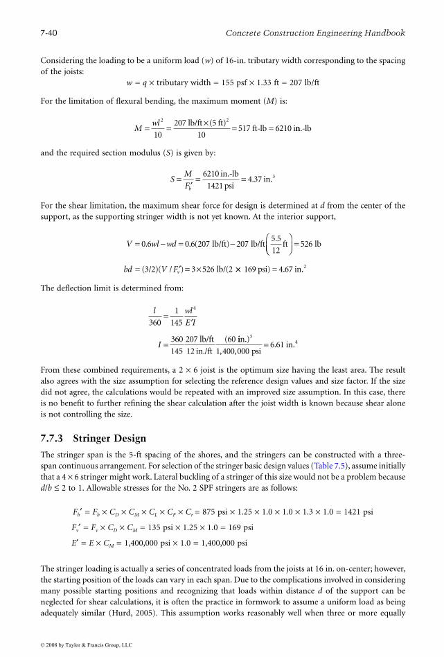
7-40 Concrete Construction Engineering Handbook
Considering the loading to be a uniform load (w) of 16-in. tributary width corresponding to the spacingof the joists:
w = q × tributary width = 155 psf × 1.33 ft = 207 lb/ft
For the limitation of flexural bending, the maximum moment (M) is:
and the required section modulus (S) is given by:
For the shear limitation, the maximum shear force for design is determined at d from the center of thesupport, as the supporting stringer width is not yet known. At the interior support,
The deflection limit is determined from:
From these combined requirements, a 2 × 6 joist is the optimum size having the least area. The resultalso agrees with the size assumption for selecting the reference design values and size factor. If the sizedid not agree, the calculations would be repeated with an improved size assumption. In this case, thereis no benefit to further refining the shear calculation after the joist width is known because shear aloneis not controlling the size.
7.7.3 Stringer Design
The stringer span is the 5-ft spacing of the shores, and the stringers can be constructed with a three-span continuous arrangement. For selection of the stringer basic design values (Table 7.5), assume initiallythat a 4 × 6 stringer might work. Lateral buckling of a stringer of this size would not be a problem becaused/b ≤ 2 to 1. Allowable stresses for the No. 2 SPF stringers are as follows:
Fb′ = Fb × CD × CM × CL × CF × Cr = 875 psi × 1.25 × 1.0 × 1.0 × 1.3 × 1.0 = 1421 psi
Fv′ = Fv × CD × CM = 135 psi × 1.25 × 1.0 = 169 psi
E′ = E × CM = 1,400,000 psi × 1.0 = 1,400,000 psi
The stringer loading is actually a series of concentrated loads from the joists at 16 in. on-center; however,the starting position of the loads can vary in each span. Due to the complications involved in consideringmany possible starting positions and recognizing that loads within distance d of the support can beneglected for shear calculations, it is often the practice in formwork to assume a uniform load as beingadequately similar (Hurd, 2005). This assumption works reasonably well when three or more equally
Mwl= = × =
2
10
207
10517
lb/ft (5 ft)ft-lb = 6210 i
2
nn.-lb
SM
Fb
=′
= =6210
14214 37
in.-lb
psiin.3.
V wl wd= − = − 0 6 0 6 207 207
5 5
12. . (
.lb/ft) lb/ft ft
=
′ = ×
526
3 526
lb
= (3/2)( lb/(2bd V Fv/ ) ×× 169 psi) = 4.67 in.2
l wl
E I
I
360
1
145
360
145
207
12
60
4
=′
= lb/ft
in./ft
( iin.)
psiin.
34
1 400 0006 61
, ,.=
© 2008 by Taylor & Francis Group, LLC

Design and Construction of Concrete Formwork 7-41
spaced concentrated loads of equal magnitude are in the span. Considering the loading to be a uniformload (w) of 5-ft tributary width corresponding to the spacing of the stringers:
w = q × tributary width = 155 psf × 5 ft = 775 lb/ft
For the limitation of flexural bending, the maximum moment (M) is:
and the required section modulus (S) is given by:
For the shear limitation, the maximum shear force for design is determined at distance d from the faceof the support, assuming the shore will be at least 4 × 4 or have a head of equal or larger size if it is ametal shore. At the interior support where shear is greatest:
The deflection limit is determined from:
From these requirements, a 4 × 6 stringer is the optimum size meeting all the requirements and havingthe least area. The result also agrees with the size assumption for selecting the reference design valuesand size factor. If the size did not agree, the calculations would be repeated with an improved sizeassumption. A check is also necessary to make sure that there is adequate bearing area for the joist onthe stringer.
The tributary load is:P = 155 psf × 1.33 ft × 5 ft = 1031 lb
The allowable bearing stress is given by:
and the actual stress is:
7.7.4 Shore Design
To determine the shore unbraced height, the slab thickness and depth of forming elements are subtractedfrom the floor-to-floor height:
le = 120 – 8 – 0.625 – 5.5 – 5.5 in. = 100.4 in.
Mwl= = × =
2
10
775
101938
lb/ft (5 ft)ft-lb = 23,2
2
550 in.-lb
SM
Fb
=′
= =23 250
142116 36
,.
in.-lb
psiin.3
V wl w d lb= − +( ) = −0 6 2 0 6 775 775. . ( lb/ft)(5 ft) lbb/ft ft lb5 5 12 3 5 2 12 1857. / ) ( . / )/+ { } =
=bd (( / ) .3 2 16 5V Fv′( ) × ==(3/2) (1857 lb/169 psi) in..2
l wl
E I
I
360
1
145
360
145
775
12
6
4
=′
= lb/ft
in./ft
( 00
1 400 00024 73
in.)
psiin.
34
, ,.=
′ = × × = × ×⊥ ⊥F F C Cc c M b 425 psi 1.0 1.0 = 425 psii
fP
Ac ⊥ = =
×=1031
1 5196
lb
in. 3.5 in.psi < 425
.psi
© 2008 by Taylor & Francis Group, LLC

7-42 Concrete Construction Engineering Handbook
For design purposes, the shore is assumed to be concentrically loaded, pinned at the top and the bottomand prevented from translation by an adequate overall form diagonal bracing system. The load to besupported based on the tributary area is:
P = 155 psf × 5 ft × 5 ft = 3875 lb
Two stress checks are necessary to size the shore: (1) the bearing perpendicular to the grain of the stringerat the upper end of the shore, and (2) the compression parallel to the grain of the shore (including thepossibility of buckling). Evaluation of bearing first will establish a first trial size of the shore area. Theallowable bearing stress is:
Cb is assumed to be 1.0, because the bearing length is not yet known and the shore may sometimes belocated at the end of the stringer. The required bearing area is given by:
A 4 × 4 shore is adequate for bearing perpendicular to the grain of the stringer and matches the widthof the 4 × 6 stringer. For this 4 × 4 shore size, the allowable compression stress parallel to grain is:
Because the trial shore is square and braced only at the ends to resist translation, the le/d ratios for eachbuckling axis are equal; thus,
and
so
and CP from Equation 7.10 is:
Thus, the allowable stress in compression parallel to the grain for the unbraced length is:
Fc′ = Fc = 1653 psi × CP = 1653 psi × 0.285 = 471 psi
Because Fc′ > Fc⊥′ , compression perpendicular to the grain in the bearing controls the design, and the4 × 4 shore is adequate.
In summary, the design requires 5/8-in. Plyform spanning the strong way, 2 × 6 joists at 16 in. on-center, 4 × 6 stringers at 5 ft on-center, and 4 × 4 shores at 5 ft on-center each way.
′ = × × = × ×⊥ ⊥F F C Cc c M b 425 psi 1.0 1.0 = 425 psii
AP
Fc
=′
= =⊥
3875
4259 12
lb
psiin.2.
F F C C C C Cc c D M F P′ = × × × × = × × × ×1150 1 25 1 0 1 15psi . . . PP P c P
M
C F C
E E C
= × = ×
′ = × =
∗1653
510 000
psi
min min , psi 1.0 = 510,000 psi×
l
de = = <100 4
3 528 68 50
.
..
in.
in.
F E l dcE e= ′ ( ) = ×0 822 0 822 510 0002
. . ,min psi (28.688) psi2 = 510
F FcE c∗ = 510 psi / 1653 psi = 0.308
CP = + × − + × ( . ) ( . ) ( . ) ( . )1 0 308 2 0 8 1 0 308 2 0 8 −{ } =2
0 5
0 308 0 8 0 285( . / . ) ..
© 2008 by Taylor & Francis Group, LLC

Design and Construction of Concrete Formwork 7-43
7.7.5 Bracing Design Considerations
The slab form must be braced, as a minimum, to resist the horizontal loads recommended by ACI 347-04.When the concrete columns have been placed prior to erection of the floor forms, the column cancontribute to lateral stability if the form has an adequate horizontal diaphragm and is tied to the columns.Horizontal cross-bracing can be added to improve the diaphragm. Vertical cross-bracing in two directionsat right angles, in combination with an adequate diaphragm, can also provide a workable system. Thebraces need not be located in the opening between every pair of shores (Figure 7.29). Often, they arelocated between alternate pairs of shores (and sometimes farther apart) in a well-dispersed, symmetricalpattern in each direction. The brace size is usually controlled by the buckling resistance in the compressiondirection of force, and the analysis and design proceed in a manner similar to that for the shore or wallform brace design. It is critical to provide a connection at the top and bottom ends of the brace that isadequate to resist the forces imposed.
7.8 Wall-Form Design Example
Assume that a form is needed for the placement of a 12-ft high wall. The general layout of the plywoodsheathing, studs, and wales is shown in Figure 7.39. Because of the availability of the material fromprevious projects, the contractor wishes to use 3/4-in. B-B Plyform, Class I, plywood for the sheathingand No. 2 Southern Pine 2 × 4 studs and double 2 × 4 wales. Ties can be ordered to meet project needs.The project specification requires that the formwork element deflections be no greater than l/240. Theplywood will be assumed to be used wet, as it is in contact with the fresh concrete, and the lumberelements will be assumed to be exposed to sufficient rain moisture on the job such that the wood moisturecontent might rise to above 19%. The normal weight 145 pcf concrete, made with Type II cement, hasa slump of <7 in. and contains a set-retarding admixture. Internal vibration during placement will becontrolled and limited to an immersion depth <4 ft. The rate of vertical placement (R) will be limitedto 4 ft per hour, and the concrete temperature (T) is expected to be above a minimum of 80°F.
From the earlier section on lateral pressures, the maximum distributed pressure (p) for design on aworking basis is given by Equation 7.2:
FIGURE 7.39 Wall-form components.
Plywood
sheathing
Stud
Wale
Tie
© 2008 by Taylor & Francis Group, LLC

7-44 Concrete Construction Engineering Handbook
The pressure is assumed to gradually increase with depth at a rate of 150 lb/ft3/ft until reaching themaximum uniform pressure at a depth of 720 psf/150 lb/ft3 or 4.8 ft. For purposes of illustrating the formdesign procedure, first consider the spacing of members in the uniform pressure region. Because the sizesof the members are predetermined, the unknowns are the maximum allowable spacings of their supports.
7.8.1 Sheathing Design
The plywood span is the spacing of the studs, and the 8-ft-long plywood panels can typically have threeor more spans. The plywood allowable stresses adjusted for load duration (see Table 7.5) are:
Fb′ = Fb × CD = 1545 psi × 1.25 = 1931 psi
Fv′ = Fv × CD = 57 psi × 1.25 = 71 psi
E′ = E = 1,500,000 psi
Considering the loading to be a uniform load (w) of 1-ft unit width corresponding to the sectionproperties of the plywood based on 12-in. width,
w = pmax × unit width = 720 psf × 1.0 ft = 720 lb/ft
For the limitation of flexural bending, the maximum allowable moment (M) is:
M = fb′S = 1931 psi × 0.455 in.3 = 878 in.-lb = 73.2 ft-lb
and the maximum span (l) is given by:
M = wl2/10
73.2 ft-lb = 720 lb/ft × l2/10
l = 1.01 ft = 12.1 in.
For the shear limitation, the support width is known to be 1.5 in., so the maximum shear force for designcan be determined at the face of the support:
For the deflection limit, the maximum span is determined from:
From these requirements, 12.1 in. (based on bending) is the maximum span of the plywood. Consideringthe 8-ft modular length of the plywood panel, provide 8 equal spans with the studs spaced at 12 in. on-center.
7.8.2 Stud Design
The stud span is the spacing of the double wales, and the studs can be constructed with a three-spancontinuous arrangement. Lateral buckling of the studs will be restrained by nailing the sheathing to thestuds. Allowable stresses for the No. 2 Southern Pine 2 × 4 stud from Table 7.5 are as follows:
p C C R TW Cmax [ / ] . . ( /= + = × + ×150 9000 1 0 1 2 150 9000 4 800 720) = psf
V F Ib Q
V wl
v= ′ = × =
=
( / )
.
71 510
0 6
psi 7.187 in. lb2
−−
= −
w l
l
b( )
. ( ( ) ( .
2
510 0 6 720 720 1 5lb lb/ft) in../2)/12 in./ft
ft in.
= =l 1 26 15 4. .
l wl E I
l
/ ( / )( )
/ ( / )
240 1 145
240 1 145 720
4= ′
= lb/ft ×× × ×( )
l 4 12 1 500 000 0 199in./ft psi in.4, , .
=l 14 4. in.
© 2008 by Taylor & Francis Group, LLC
Design and Construction of Concrete Formwork 7-45
Fb′ = Fb × CD × CM × CL × CF × Cr = 1500 psi × 1.25 × 0.85 × 1.0 × 1.0 × 1.0 = 1593 psi
Fv′ = Fv × CD × CM = 175 psi × 1.25 × 0.97 = 212 psi
E′ = E × CM = 1,600,000 psi × 0.9 = 1,440,000 psi
Considering the loading as a uniform load (w) of 12-in. tributary width corresponding to the spacingof the studs,
w = q × tributary width = 720 psf × 1.0 ft = 720 lb/ft
For the limitation of flexural bending, the maximum allowable moment (M) is:
M = Fb′S = 1593 psi × 3.063 in.3 = 4879 in.-lb = 406.6 ft-lb
and the maximum allowable span is given by:
M = wl2/10
406.6 ft-lb = 720 lb/ft × l2/10
l = 2.37 ft = 28.5 in.
For the shear limitation, the maximum shear force for design is determined at distance d from the faceof the support because the supporting wale width (2 × 1.5 in. = 3 in.) is known. At the interior supportwhere shear is greatest:
The deflection limit is determined from:
From these requirements, the spans for bending and shear control the maximum span, which is 28.5 in.Use 28 in. for layout convenience.
7.8.3 Wale Design
The wale span is the spacing of the form ties, and the wales can be constructed with a three-span continuousarrangement. Lateral buckling of the wale is not a problem because d/b ≤ 2 to 1. Allowable stresses for theNo. 2 Southern Pine double 2 × 4 wales are the same as determined above for the studs. The wale loadingis actually a series of concentrated loads from the studs at 12 in. on-center; however, the starting positionof the loads can vary in each span. Due to the complications involved in considering the many possiblestarting positions and recognizing that loads within distance d of the support can be neglected for shearcalculations, it is often the practice in formwork to assume a uniform load to be adequately similar tomany closely spaced equally concentrated loads (Hurd, 2005). This assumption works reasonably wellwhen three or more equally spaced concentrated loads of equal magnitude are in the span. Consideringthe loading to be a uniform load (w) of 2.33-ft tributary width corresponding to the spacing of the wales,
w = q × tributary width = 720 psf × 2.33 ft = 1680 lb/ft
V F bdv= ′ = × × × =( / ) ( / ) . .2 3 2 3 212 1 5 3 5 7psi in. in 442
0 6 2
742
lb
lb = 0.6(720 lb/f
V wl w d lb= − +. ( )
tt)( lb/ft ftl) . / ) ( . / )− + { }720 3 5 12 3 0 2 12 = 1857 lb
ft = 28.9 in.l = 2 41.
l wl E I
l
/ ( / )( )
/ ( / )
240 1 145
240 1 145 720
4= ′
= lb/ft ×× × ×( )
l 4 12 1 440 000in./ft psi 5.359 in.4, ,
=l 42 6. in.
© 2008 by Taylor & Francis Group, LLC

7-46 Concrete Construction Engineering Handbook
For the limitation of flexural bending, the maximum allowable moment (M) is:
M = Fb′S = 1593 psi × 2 × 3.063 in.3 = 9758 in.-lb = 813 ft-lb
and the maximum allowable span is given by:
M = wl2/10
813 ft-lb = 1680 lb/ft × l2/10
l = 2.2 ft = 26.4 in.
For the shear limitation, the maximum shear force for design is determined at distance d from the faceof the support assuming that the tie-washer plate will have at least a 3-in. length of bearing. The waleinterior support is examined where shear is greatest. At the interior support:
The deflection limit is determined from:
From these requirements, the maximum span is 26.0 in. and is controlled by shear. Select a wale spanof 24 in. so the tie spacing can be coordinated easily with the stud spacing.
A check is also needed to make sure that there is adequate bearing area for the stud on the doublewale. The tributary load is:
P = 720 psf × 1.0 ft × 2.33 ft = 1678 lb
The allowable bearing stress is given by:
F′c⊥ = Fc⊥ × CM × Cb = 565 psi × 0.67 × 1.0 = 378 psi
and the actual stress is:
fc⊥ = P/A = 1678 lb/(1.5 in. × 3.0 in.) = 373 psi < 378 psi
7.8.4 Tie Design
Select the tie capacity to exceed the tie force (T) based on the tributary area supported:
T = pmax × wale spacing × tie spacing = 720 psf × 2.33.ft × 2.0 ft = 3350 lb
Select a heavy snap tie with a 3350-lb working capacity, and check the bearing of the 3-in. square tiewasher on the double wale (Figure 7.40):
fc⊥ = P/A = 3350 lb/(2 × 1.5 in. × 3.0 in.) = 372 psi < 378 psi
7.8.5 Bracing Design
Braces are required to keep the form from overturning due to wind or incidental construction loads suchas ladders leaning on the form or workers climbing on the form. The effects of an elevated work platformmay also have to be considered in some designs. If designing for the minimum recommendations of ACI
V F bdv= ′ = × × × ×( / ) ( / ) . .2 3 2 3 212 2 1 5 3 5psi in. in.. = 1484 lb
lb = 0.6(1
V wl w d lb= − +( )0 6 2
1484
.
6680 lb/ft)( lb/ft (3.5/12)+(3.0/2)1l)−1680 22 ft
ft = 26.0 in.
{ }=l 2 17.
l wl E I
l
/ ( / )( )
/ ( / )
240 1 145
240 1 145 1680
4= ′
= lb/ftt in./ft psi 5.359 in.4× × ×( )l 4 12 1 440 000, ,
=l 40 5. in.
© 2008 by Taylor & Francis Group, LLC

Design and Construction of Concrete Formwork 7-47
347-04, the loadings would include a wind pressure of 15 psf or a line load of 100 lb/linear foot at thetop, whichever is greater. The contractor desires to lay out the braces as shown in Figure 7.41, with thebraces at 4 ft on-center, the brace attached at an elevation of 10 ft on the 12-ft form, and the braceanchored to the ground 7.5 ft from the form. This results in a brace length of 12.5 ft, including theadjustable connectors at each end. For design purposes, the brace is assumed to be concentrically loaded,pinned at the top and the bottom, and prevented from translation by the longitudinal rigidity of theform. The horizontal brace load (H) from the wind is:
H = 15 psf × 4 ft × 12 ft × 6 ft/10 ft = 432 lb
Alternatively, the horizontal brace load from the 100 lb/ft line load is:
H = 100 lb/ft × 4 ft × 12 ft/10 ft = 480 lb
FIGURE 7.40 Bearing of form tie bracket on double wood wale.
FIGURE 7.41 Layout of wall-form members.
12
'-0
"
4.4
'
720psf
10
"2
8"
10
"2
8"
28
"3
8"
12
"
7'-6"
10
'-0
"
l/2
l/2
© 2008 by Taylor & Francis Group, LLC
7-48 Concrete Construction Engineering Handbook
The brace should be designed to resist a horizontal component of 480 lb, which results in an axialcompression force (P) of:
P = 480 lb × 12.5 ft/7.5 ft = 800 lb
Try a No. 2 Southern Pine 2 × 4 brace with a bracing strut at mid-length in the weak buckling direction.For this 2 × 4 size, the allowable compression stress is:
Fc′ = Fc × CD × CM × CF × CP = 1650 psi × 1.25 × 0.8 × 1.0 × CP = 1650 psi × CP = Fc* × CP
E ′min = Emin × CM = 580,000 psi × 0.8 = 464,000 psi
Because the trial brace is rectangular, check the le/d ratios for each buckling axis:
For this short-term construction period loading, a le/d limit of 75 might also be considered if necessary.Thus, the weak axis controls, and le/d = 50. Substituting to determine CP:
so
FcE/Fc* = 152 psi/1650 psi = 0.092
and CP from Equation 7.10 is:
Thus, the allowable stress in compression parallel to the grain for the unbraced length is:
Fc′ = Fc* × CP = 1650 psi × CP = 1650 psi × 0.090 = 149 psi
fc = P/A = 800 lb / 5.25 in.2 = 153 psi > 149 psi (not adequate)
The 2 × 4 brace with the mid-length strut is slightly less than the needed section. Increase to a 2 × 6brace with a mid-length strut, which will be adequate based on the increased area. Alternatively, a steel-pipe brace rated for the load at the extended length of 12.5 ft could be used. Appropriate connection,adequate for a tension or compression of 800 lb, must be made at the top and bottom ends of the braceby bolting, nailing, or use of a rated commercial hardware device, without inducing significant eccen-tricities.
A possible layout for the wall form is shown in Figure 7.41. The top and bottom extensions of thestuds beyond the wales are usually about 1/3 of the adjacent span up to perhaps 12 in. At the top of theform, where the pressures are lower, the span of the studs can be investigated with ramp loading, andthe wale spacing can often be increased, sometimes eliminating a level of wales and ties in comparisonto the number required for a constant spacing. Careful consideration of all design details, communicatingthese requirements to the form craftspersons, and providing knowledgeable verification of execution canlead to safe and economical support of concrete during construction.
l
d
l
d
1
1
2
2
150
3 542 8 50
75
1 5
= = ≤
=
in.
in.
in.
i
..
. nn.= ≤50 0 50.
F E l dcE e= ′ = ×0 822 0 822 464 0002. ( ) . ,min psi (50.0)) psi2 = 152
CP = + × − + ×( . )/( . ) ( . )/( . )1 0 092 2 0 8 1 0 092 2 0 8 −{ } =2
0 5
0 092 0 8 0 090( . / . ) ..
© 2008 by Taylor & Francis Group, LLC

References
ACI Committee 347. 2004. Guide to Formwork for Concrete, ACI 347-04, 34 pp. American ConcreteInstitute, Farmington Hills, MI.
ACI Committee 347, 2005. Guide to Shoring and Reshoring of Multistory Concrete Buildings, ACI 347.2R-05, 18 pp. American Concrete Institute, Farmington Hills, MI.
AFPA. 2005. National Design Specification for Wood Construction ASD/LRFD, ANSI/AF&PA NDS-2005.American Forest and Paper Association, Washington, D.C.
APA. 1997. Plywood Design Specification, 31 pp. APA—The Engineered Wood Association, Tacoma, WA.APA. 2004. Concrete Forming, 27 pp. APA—The Engineered Wood Association, Tacoma, WA.ASCE. 2002. Design Loads on Structures during Construction, ASCE/SEI 37-02. American Society of Civil
Engineers, Reston, VA.Hurd, M.K. 2005. Formwork for Concrete, 7th ed., SP-4. American Concrete Institute, Farmington Hills,
MI.
Further Information
Aluminum Association, 1525 Wilson Boulevard, Suite 600, Arlington, VA 22209, www.aluminum.org.American Concrete Institute, P.O. Box 9094, Farmington Hills, MI 48333-9094, www.concrete.org.American Forest and Paper Association/American Wood Council, 1111 19th Street, Suite 800, Washing-
ton, D.C. 20036, www.awc.org.American National Standards Institute, 11 West 42 Street, New York, NY 10036, www.ansi.org.American Society of Civil Engineers, 1801 Alexander Bell Drive, Reston, VA 20191-4400, www.asce.org.APA—The Engineered Wood Association, 7011 S. 19th Street, Tacoma, WA 98466, www.apawood.org.Scaffolding, Shoring and Forming Institute, Inc., 1300 Sumner Avenue, Cleveland, OH 44115-2851,
www.ssfi.org.
© 2008 by Taylor & Francis Group, LLC

(a) Construction loading in high-rise buildings. (Photograph courtesy of Portland Cement Association, Skokie, IL.)(b) Ronald McDonald House under construction in New York. (Photograph courtesy of New York Construction Newsand Edward G. Nawy, Rutgers University.)
(a)
(b)
© 2008 by Taylor & Francis Group, LLC