
Design and Construction of Chem-E-Car SMARTTRONS...
12
Journal of Physical Science, Vol. 29(Supp. 2), 203–214, 2018 © Penerbit Universiti Sains Malaysia, 2018. This work is licensed under the terms of the Creative Commons Attribution (CC BY) (http://creativecommons.org/licenses/by/4.0/). Design and Construction of Chem-E-Car SMARTTRONS Powered by Thermoelectric Generator Utilising Temperature Gradient of Two Reactors Dhoni Hartanto, 1* Waliyuddin Sammadikun, 1 Akhmad Sutrisno, 1 Abdul Basit, 2 Ade Surya Siladryanto, 3 Bayu Triwibowo, 1 Haniif Prasetiawan, 1 Widi Astuti, 1 Megawati, 1 Achmad Chafidz, 4 Wara Dyah Pita Rengga, 1 Ratna Dewi Kusumaningtyas 1 and Ianatul Khoiroh 5 1 Department of Chemical Engineering, Faculty of Engineering, Universitas Negeri Semarang, Kampus Sekaran Gunungpati, Semarang 50229, Indonesia 2 Department of Electrical Engineering, Faculty of Engineering, Universitas Negeri Semarang, Kampus Sekaran Gunungpati, Semarang 50229, Indonesia 3 Department of Mechanical Engineering, Faculty of Engineering, Universitas Negeri Semarang, Kampus Sekaran Gunungpati, Semarang 50229, Indonesia 4 Department of Chemical Engineering, Universitas Islam Indonesia, Yogyakarta 55584, Indonesia 5 Department of Chemical and Environmental Engineering, Faculty of Engineering, University of Nottingham Malaysia Campus, Jalan Broga, Semenyih, 43500 Selangor, Malaysia * Corresponding author: [email protected] Published online: 30 July 2018 To cite this article: Hartanto, D. et al. (2018). Design and construction of Chem-E-Car SMARTTRONS powered by thermoelectric generator utilising temperature gradient of two reactors. J. Phys. Sci., 29(Supp. 2), 203–214, https://doi.org/10.21315/jps2018.29. s2.16 To link to this article: https://doi.org/10.21315/jps2018.29.s2.16 ABSTRACT: SMARTTRONS is an engineering car developed by the Department of Chemical Engineering, Universitas Negeri Semarang, Indonesia, to compete in the annual Chem-E-Car competition. This car is powered by a set of thermoelectric generators (TEG), which utilises the heat gradient between two reactors: hot reactor (i.e., reaction of CaO + H 2 O) and cold reactor (ice + NaCl), with an average temperature gradient of 83.4°C (356.55 K). The heat flux produced by the temperature difference is then converted into electric energy by the help of eight TEGs, which generate a maximum voltage of 34.8 V. The temperature profile was analysed using computational fluid dynamics (CFD) to gain understanding of the heat distribution for the heat sink. The sodium thiosulfate clock reaction was used as a stopping mechanism which stopped the car at a predicted time limit.
Transcript of Design and Construction of Chem-E-Car SMARTTRONS...

Journal of Physical Science, Vol. 29(Supp. 2), 203–214, 2018
© Penerbit Universiti Sains Malaysia, 2018. This work is licensed under the terms of the Creative Commons Attribution (CC BY) (http://creativecommons.org/licenses/by/4.0/).
Design and Construction of Chem-E-Car SMARTTRONS Powered by Thermoelectric Generator Utilising Temperature Gradient
of Two Reactors
Dhoni Hartanto,1* Waliyuddin Sammadikun,1 Akhmad Sutrisno,1 Abdul Basit,2 Ade Surya Siladryanto,3 Bayu Triwibowo,1 Haniif Prasetiawan,1 Widi Astuti,1 Megawati,1 Achmad Chafidz,4 Wara Dyah Pita Rengga,1 Ratna Dewi Kusumaningtyas1 and Ianatul Khoiroh5
1Department of Chemical Engineering, Faculty of Engineering, Universitas Negeri Semarang, Kampus Sekaran Gunungpati, Semarang 50229, Indonesia
2Department of Electrical Engineering, Faculty of Engineering, Universitas Negeri Semarang, Kampus Sekaran Gunungpati, Semarang 50229, Indonesia
3Department of Mechanical Engineering, Faculty of Engineering, Universitas Negeri Semarang, Kampus Sekaran Gunungpati, Semarang 50229, Indonesia
4Department of Chemical Engineering, Universitas Islam Indonesia, Yogyakarta 55584, Indonesia
5Department of Chemical and Environmental Engineering, Faculty of Engineering, University of Nottingham Malaysia Campus, Jalan Broga,
Semenyih, 43500 Selangor, Malaysia
*Corresponding author: [email protected]
Published online: 30 July 2018
To cite this article: Hartanto, D. et al. (2018). Design and construction of Chem-E-Car SMARTTRONS powered by thermoelectric generator utilising temperature gradient of two reactors. J. Phys. Sci., 29(Supp. 2), 203–214, https://doi.org/10.21315/jps2018.29.s2.16
To link to this article: https://doi.org/10.21315/jps2018.29.s2.16
ABSTRACT: SMARTTRONS is an engineering car developed by the Department of Chemical Engineering, Universitas Negeri Semarang, Indonesia, to compete in the annual Chem-E-Car competition. This car is powered by a set of thermoelectric generators (TEG), which utilises the heat gradient between two reactors: hot reactor (i.e., reaction of CaO + H2O) and cold reactor (ice + NaCl), with an average temperature gradient of 83.4°C (356.55 K). The heat flux produced by the temperature difference is then converted into electric energy by the help of eight TEGs, which generate a maximum voltage of 34.8 V. The temperature profile was analysed using computational fluid dynamics (CFD) to gain understanding of the heat distribution for the heat sink. The sodium thiosulfate clock reaction was used as a stopping mechanism which stopped the car at a predicted time limit.
Design and Construction of Chem-E-Car 204
Additionally, a unique feature of this car is that the reactor and body of the car are mostly made from renewable local materials, i.e., wood and rattan.
Keywords: Chem-E-Car, heat gradient, power source, computational fluid dynamics, thermoelectric generator
1. INTRODUCTION
Chem-E-Car competition was first launched by the American Institute of Chemical Engineers (AIChE) to attract participants (especially engineering students) and motivate them to design and construct a prototype car powered by chemical reactions. This competition has grown from regional to international level. The rules are always being updated to increase the difficulty and challenge participants to design prototype cars for specific rules. The car needs to travel a particular distance and has to carry a certain amount of weight, which would be announced shortly before the competition starts. This additional criterion will increase the difficulty of the race. The main objective of this competition is to achieve educational outcomes such as developing hard and soft skills among participating contestants.1–4 In general, students from three different engineering majors (i.e., chemical, mechanical and electrical engineering) can participate in the Chem-E-Car design and fabrication. The three main aspects of the design are mechanism of power source, stopping mechanism and aerodynamic behaviour.5 These aspects involve chemical engineering optimisation which can be obtained from data research.6–12
The most common design mechanisms in the competition involve galvanic/voltaic cells, built-up pressure and fuel cell technology. The galvanic/voltaic cell utilises electrochemical reaction to produce electricity. This electric current is transferred to an electric motor to run the car. The fuel cell technology meanwhile utilises reaction between hydrogen and oxygen to produce electricity to run the car. The built-up pressure concept uses gas products obtained from a chemical reaction. The produced gas increases the pressure that can be converted using pneumatic actuator to move the car’s wheels. Biological reactions have also been used by participants, but they are less utilised now due to low electricity production and result in slow movement.13 Each power source mechanism mentioned has advantages and disadvantages. For example, the power source obtained from the built-up pressure concept is the most powerful, but because it requires high pressure, the reaction tank must have a thick shell. This would affect the production cost as well as the safety and total weight of the car. It might not be efficient to run a car with a heavy load. Whereas, for the stopping mechanism, an iodine clock is a reaction

Journal of Physical Science, Vol. 29(Supp. 2), 203–214, 2018 205
commonly used in Chem-E-Car development. The car will stop moving when the solution turns dark due to the iodine reaction, which subsequently cut off the electrical circuit through a photosensor.14
A group of chemical engineering students from the Universitas Negeri Semarang (UNNES) has designed a Chem-E-Car prototype named Semarang Robotic Technology of UNNES’s Chemical Cars, or in short, SMARTTRONS. A combination of wood material and rattan was used to build the reactor and car body. In this car design, three reactors were used as the power source and were placed over the back wheels. Two reactors were used for exothermic reaction which acted as the hot reactors, whereas the third reactor was employed as a cooling bath, that is, the cold reactor. The stopping mechanism chosen followed the principle of the sodium thiosulfate clock reaction, which stopped the car once the reaction was completed. In the current study, the power generation and stopping mechanism of SMARTTRONS have been evaluated. To the best of our knowledge, research studies on similar Chem-E-Car concept are unavailable in the open literature.
2. EXPERIMENTAL
2.1 Materials
The chemicals used for the main reaction (i.e., power source) and stopping mechanism were technical grade calcium oxide (CaO), sodium chloride (NaCl), sodium thiosulfate (Na2S2O3) and hydrochloric acid (HCl). All chemicals were obtained from a local market in Semarang city, Indonesia. The water supplied from a laboratory was also used in this work. The materials used in the car, i.e., wood and rattan were also obtained from Semarang. Thermoelectric generator (TEG SP1848-27145 SA, China) was used in the car design.
2.2 Methods
Several experiments were conducted to analyse specific properties and parameters that affect the car performance. The experimental study consists of two analyses, which are the power source and stopping mechanism.
2.2.1 Power source
The hot-side reactor chambers were filled with 336 g of CaO and 90 ml of water, which initiated a chemical reaction to form calcium hydroxide. The reaction itself is an exothermic reaction which released heat. The maximum temperature

Design and Construction of Chem-E-Car 206
achieved was approximately 90°C (363.15 K). The reactor chambers were isolated using aluminium foil to keep the heat and prevent heat loss to the surroundings. Whereas, the cold-side chamber was filled with a mixture of 200 g of NaCl and 600 g of ice, which produced a minimum temperature of –6.5°C (266.65 K). The temperature gradient between the cold-side and hot-side chambers acted as the power source or driving force to produce electricity. Eight thermoelectric generators were placed between the cold-side chamber and the hot-side chambers, which converted the temperature gradient into electrical power. The voltage produced by thermoelectricity, which was connected in a series, was measured over a period of 352 using an analogue multimeter (1000 V, Sanwa, Japan). The temperature profiles of the cold-side and hot-side reactors were measured using a digital thermometer (TES 1310 type-K), with an accuracy of ±0.1 K. The temperature distribution of the heat sink in the thermoelectric generator was further simulated by using computational fluid dynamics (CFD) ANSYS 14.5.
2.2.2 Stopping mechanism
Na2S2O3 clock reaction was selected as the stopping mechanism for the SMARTTRONS. The reaction between Na2S2O3 and HCl produced NaCl, SO2 and water. The reaction completed when there was a change in colour from clear to opaque white. The change in colour of the sodium thiosulfate clock solution resulted in a change in the light-dependent resistor value. The duration of the sodium thiosulfate clock reaction was dependent on the molarity of the sodium thiosulfate used in the reaction, hence the volume and concentration of HCl were fixed at 10 ml and 1 M, respectively. A black reaction vessel was used to isolate the reaction from the ambient light. The vessel was modified with a small hole at the top of the vessel to allow the injection of the solution into the chamber using a syringe. The syringe was mounted in the vessel while the car was moving forward. About 10 ml of 1 M of HCl was injected first into the vessel, followed by an injection of 20 ml of Na2S2O3 at concentrations of 0.04 M, 0.05 M, 0.06 M, 0.07 M, 0.08 M, 0.09 M and 0.10 M. The effect of Na2S2O3 concentration on the stopping time of the car was analysed and a mathematical model for the curve was generated.
3. RESULTS AND DISCUSSION
3.1 Design of the Chem-E-Car SMARTTRONS
The SMARTTRONS car prototype has the dimension of 35 cm × 25 cm × 18 cm. A wood material was used for the reactor and chassis, whereas rattan material was used for the car body. Wood and rattan are abundant natural resources and easy

Journal of Physical Science, Vol. 29(Supp. 2), 203–214, 2018 207
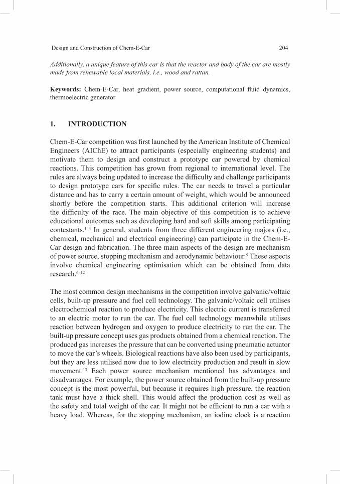
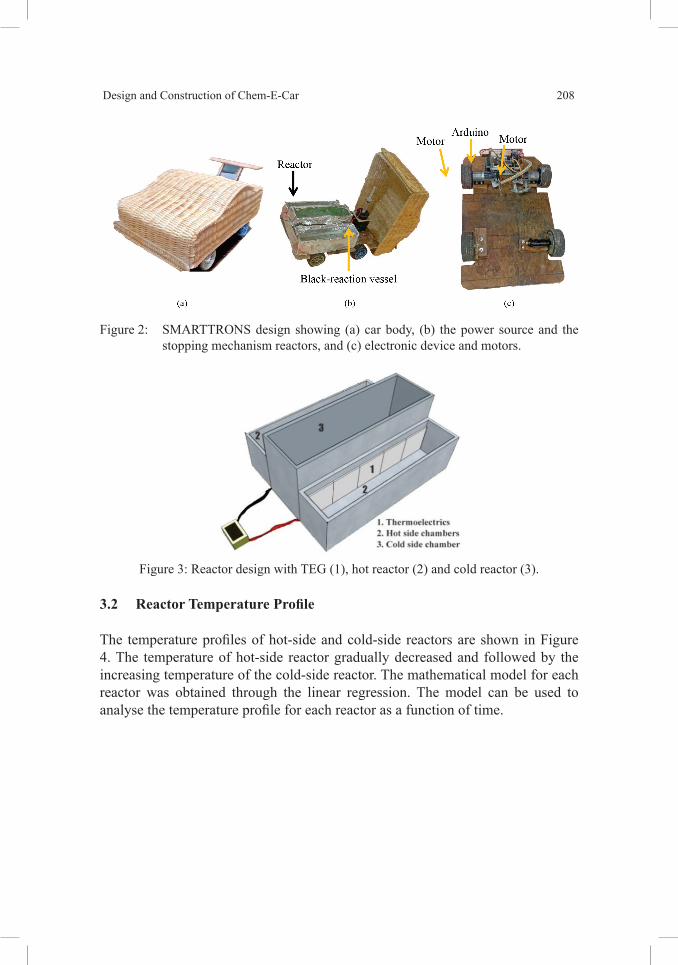
to obtain at a very low price. Moreover, they have strength properties which are comparable to conventional materials. The car has four wheels with two DC motor as the wheels drive or called 2WD. An Arduino microcontroller was employed to detect the colour change in the sodium thiosulfate clock reaction. The isolated vessel was used as the place for the stopping mechanism reaction. The SMARTTRONS schematic and design are depicted in Figures 1 and 2, respectively. Two reactors used for exothermic reaction as hot reactor and one reactor for cooling bath as a cold reactor. The dimension of hot reactors and cold reactor were 22 cm × 5 cm × 6 cm and 22 cm × 6 cm × 6 cm, respectively, as shown in Figure 3. The reactor was covered using aluminium foil to keep the heat produced in the hot side reactor. Additionally, the car was also designed with the number of features which provide maximum safety operation. The hazard mitigation has been measured as follow: (1) coating the hot container with aluminium foil; (2) the vessel for sodium thiosulfate vessel must be closed very well to prevent exposure to the light; (3) car equipment and wiring are properly secured to prevent movement which can cause damage to the car; (4) low voltage and current are applied in the power supply of the vehicle to prevent electrical hazard; (5) the electrical components are also properly secured to prevent from the liquid drop; and (6) wood was used as a reactor material which also acted as an insulator material due to its lower heat conductivity.
Figure 1: Schematic of SMARTTRONS.
Design and Construction of Chem-E-Car 208
Figure 2: SMARTTRONS design showing (a) car body, (b) the power source and the stopping mechanism reactors, and (c) electronic device and motors.
Figure 3: Reactor design with TEG (1), hot reactor (2) and cold reactor (3).
3.2 Reactor Temperature Profile
The temperature profiles of hot-side and cold-side reactors are shown in Figure 4. The temperature of hot-side reactor gradually decreased and followed by the increasing temperature of the cold-side reactor. The mathematical model for each reactor was obtained through the linear regression. The model can be used to analyse the temperature profile for each reactor as a function of time.

Journal of Physical Science, Vol. 29(Supp. 2), 203–214, 2018 209
Figure 4: The temperature profile of hot-side and cold-side reactors.
3.3 Voltage Profile
The voltage profile of the car is shown in Figure 5. The voltage produced gradually decreased with the time. The mathematical model was also generated through linear regression. This model can be used to predict the voltage generated during a certain period.
Figure 5: Voltage profile.

Design and Construction of Chem-E-Car 210
3.4 Heat Sink Temperature Profile with CFD Simulation
The heat sink is one of the important Chem-E-Car components to control heat under both forced and natural convection. The aim for heat sink simulation based on CFD was to obtain temperature distribution. The CFD modelling of electronic components becomes increasingly important in the design process. The model should be included in energy balance to obtain the temperature profile. The equation for energy balance is shown in Equation 1:
( ) .( )) .( ( . ))t E v E p k T h J v Seff j j j eff h22
d d d /t t x+ + = - + + (1)
where keff is effective conductivity and Jj is diffusion flux. Sh is a source term which in this case was natural convection generated from each base plate.15 In this project, heat sink component was built from bismuth with heat dissipation rate of 1.6 W m–3. The geometry of the heat sink is shown in Figure 6.
Figure 6: SMARTTRONS project heat sink geometry.
The heat sink is constructed from 196 pillars with a dimension of 1 mm × 1 mm and was trapped between two plates. The distance between two plates is 3 mm and 2.8 mm between the centre point of each pillar. The top and bottom plate have a dimension of 40 mm × 40 mm with 1 mm thickness. The grid generation was further constructed to different boundary conditions to solve the temperature profile. The boundary conditions for heat sink is shown in Figure 7.

Journal of Physical Science, Vol. 29(Supp. 2), 203–214, 2018 211
Figure 7: Boundary conditions of SMARTTRONS project heat sink (A = top plate defined as the wall; B = bottom plate defined as the wall; C = side of the bottom and top plate defined as the wall where heat flux equals 0; D = pillars defined as convection wall which where natural convection occurred).
Full hexahedral with 3987 elements were selected in the heat sink meshing, with average skewness of 0.113 was considered as an excellent meshing (average skewness < 0.25). The CFD simulation has been conducted for natural convection phenomenon between two heat sink plate at steady state condition. The temperature distribution inside the heat sink is shown in Figure 8.
Figure 8: Temperature distribution profile of SMARTTRONS project heat sink.
As the boundary conditions, the heat sink was divided into three regions which are top plate, bottom plate and pillars (convection region). The heat transfer was occurring from bottom plate to top plate. The range of temperature of the heat sink was 363 K (bottom plate) to 267 K (top plate). However, each region has different trends of temperature profile. The temperature profile of each region is shown in Table 1.

Design and Construction of Chem-E-Car 212
Table 1: Temperature distribution profile of SMARTTRONS project heat sink.
Region Highest temperature (K)
Lowest temperature (K)
Temperature difference (K)
Bottom plate 363 336 27
Pillar bottom half 336 310 26
Top half 310 288 22
Top plate 288 267 21
According to the table, the load to dissipate the temperature was almost evenly distributed. However, there was a slightly different load shown by the temperature difference from each region. The region around the bottom plate (hot side) has a relatively higher load of work due to higher heat dissipation. The variety of temperature difference between each region exhibited uneven heat dissipation. The heat sink needs to be built asymmetrically, in which the bottom plate is thicker so that a load of heat dissipation will distribute evenly.
3.5 Stopping Mechanism
The stopping mechanism analysis result is exhibited in Figure 9. As seen in the figure, the time of sodium thiosulfate clock reaction decreased exponentially when the concentration of sodium thiosulfate increased. The mathematical model of the stopping mechanism was generated through exponential regression. This model can be used to calculate the sodium thiosulfate concentration required for the car to stop at the desired distance by assuming the car speed is constant.
Figure 9: Stopping mechanism performance, i.e., concentration of sodium thiosulfate with time.
Journal of Physical Science, Vol. 29(Supp. 2), 203–214, 2018 213
4. CONCLUSION
In this study, SMARTTRONS car prototype has been designed and constructed using eco-friendly materials such as wood and rattan. The car is powered by a set of TEG, which utilises the temperature gradient between the hot-side and cold-side reactors with an average temperature gradient of 83.4°C (356.55 K). The TEG were placed on both sides of the reactors. The car was also designed for the maximum safety consideration. Based on the results, the temperature of hot-side reactor gradually decreased as followed by the increase of temperature of the cold-side reactor. Temperature distribution profile of the car heat sink has been modelled using CFD analysis. The CFD analysis showed different trends of temperature profile for each region which showed uneven heat dissipation. The asymmetrical heat sink geometry was recommended for the future study. Whereas, the stopping mechanism analysis result showed that the higher concentration of sodium thiosulfate, the faster the car comes to a stop.
5. ACKNOWLEDGEMENTS
The authors gratefully acknowledge the financial and laboratory support from Faculty of Engineering, Chemical Engineering Department Laboratory, and Jurnal Bahan Alam Terbarukan Universitas Negeri Semarang, Indonesia through grant no. 5245/UN37.1.5/LT/2017.
6. REFERENCES
1. IChemE. (2009). Accreditation of Chemical Engineering degrees: A guide for university departments and assessors based on learning outcomes master and bachelor level degree programmes. Warwickshire: IChemE.
2. ABET. (2016). Criteria for accrediting engineering programs 2016–2017. Retrieved from http://www.abet.org/accreditation/accreditation-Criteria/criteria-for-Accrediting-Engineering-Programs-2016-2017/#faculty on 12 September 2017.
3. Kamaruddin, S. K. et al. (2012). Soft skill development via Chem-E-Car project. Proc. Soc. Behav. Sci., 60, 507–511, https://doi.org/10.1016/j.sbspro.2012.09.415.
4. Masdara, M. S. et al. (2012). UKM Chem-E-Car history, implementation and achievement. Proc. Soc. Behav. Sci., 60, 468–471, https://doi.org/10.1016/j.sbspro.2012.09.408.

Design and Construction of Chem-E-Car 214
5. Lewis, R. S., Moshfeghian, A. & Madihally, S. V. (2006). Engineering analysis in the Chem-E-Car competition. Chem. Eng. Edu., 40 (1), 66–72.
6. Hardjono et al. (2017). Isobaric vapor-liquid equilibrium of 2-propanone+2-butanol system at 101.325 kPa: Experimental and molecular dynamics simulation. Korean J. Chem. Eng., 34 (7), 2011–2018, https://doi.org/10.1007/s11814-017-0089-y.
7. Hartanto, D., Mustain, A. & Nugroho, F. D. (2016). Prediction of vapor-liquid equilibria for the alcohol + glycerol systems using UNIFAC and modified UNIFAC (Dortmund). Paper presented at the AIP Conference Proceedings, Semarang, Indonesia, 5–6 October, https://doi.org/10.1063/1.4976881.
8. Hartanto, D. et al. (2016). Isobaric vapour-liquid equilibrium of (tert-butanol + water) system with biological buffer TRIS at 101.3 kPa. J. Chem. Thermod., 98, 159–164, https://doi.org/10.1016/j.jct.2016.03.013.
9. Fardhyanti D. S., Sediawan, W. B. & Mulyono, P. (2016). Predicting the liquid phase equilibrium of multi-components extraction by thermodynamic models. IJoT, 19(2), 110–119, http://dx.doi.org/10.5541/ijot.5000168952.
10. Mustain, A., Hartanto, D. & Altway, S. (2016). Compilation of extended binary interaction parameters for alcohols mixtures encountered in alcohol separation process. ARPN-JEAS, 11(5), 3465–3472.
11. Mustain, A., Takwanto, A. & Hartanto, D. (2016). Parameter interaksi biner kesetimbangan uap-cair campuran alkohol untuk optimasi proses pemurnian bioetanol. JBAT, 5(2), 37–44, https://doi.org/10.15294/jbat.v4i2.5126.
12. Megawati et al. (2015). Sulfuric acid hydrolysis of various lignocellulosic materials and its mixture in ethanol production. Biofuels, 6(5–6), 331–340, https://doi.org/10.1080/17597269.2015.1110774.
13. Masdar, M. S. et al. (2015). Engineering analysis in co-curricular student program of Chem-E-Car. Paper presented at the CAASR International Conference on Innovative Engineering and Technologies & Advanced Theoretical Computer Applications Proceeding, Bangkok, Thailand, 27–28 November, 121–133, https://doi.org/10.18797/CAASR/ICIET/2015/11/27/10.
14. Brown, T. L. et al. (2014). Chemistry, the central science, 13th ed. London: Pearson.
15. Triwibowo, B. (2013). Teori dasar simulasi proses pembakaran limbah vinasse dari industri alkohol berbasis CFD. JBAT, 2(2), 14–24, https://doi.org/10.15294/jbat.v2i2.2795.


![Daftar Pustaka · 108 Universitas Kristen Maranatha Daftar Pustaka [1] J. C. Prasetiawan, "JOB MATCHING PADA DATA I-CDC MENGGUNAKAN LATENT SEMANTIC," p. 1, 2012.](https://static.fdocuments.net/doc/165x107/6099ce1ca730aa10cc60e489/daftar-pustaka-108-universitas-kristen-maranatha-daftar-pustaka-1-j-c-prasetiawan.jpg)


