![HOM Damper Hardware Considerations for Future Energy ...Figure 8 : Layout of the broadband coaxial line to dual ridge waveguide transition [13 ]. Figure 9 : Comparison of the dual](https://static.fdocuments.net/doc/165x107/60bb38b4f37f0515537907e2/hom-damper-hardware-considerations-for-future-energy-figure-8-layout-of-the.jpg)
Design and Comparison of Dual Coaxial and edge feed …iosrjen.org/Papers/vol3_issue4...
10
IOSR Journal of Engineering (IOSRJEN) e-ISSN: 2250-3021, p-ISSN: 2278-8719 Vol. 3, Issue 4 (April. 2013), ||V4 || PP 24-33 www.iosrjen.org 24 | P a g e Design and Comparison of Dual Coaxial and edge feed Square Micro Strip Patch Antenna for Wind Profiling Radar Applications at 430 Mhz Debajyoti Chatterjee 1 Dr. P.V.Y Jayasree 2 Dr.P.Srinivasulu 3 1 (M.Tech, RF & Microwave Communication, ECE, GITAM. University, India) 2 (Associate Professor , ECE Department, GITAM. University, India) 3 (Scientist-SF, National Atmospheric Research Laboratory, Tirupati, India) Abstract: In the recent years the development in communication systems requires the development of low cost, minimal weight and low profile antennas that are capable of maintaining high performance over a wide spectrum of frequencies. This technological trend has focused much effort into the design of a microstrip patch antenna. This paper focuses on the design, model and simulation of a microstrip patch antenna which operates at 430 MHz by applying two well known and mostly used feeding techniques. Those are coaxial feeding and the strip line feeding. The proposed antenna is excited through these two feeding techniques and the antenna design has been executed and simulated using IE3D software. Therefore, method of moments based IE3D software is used to design a Microstrip Patch Antenna with dual Polarization using Dual feed line.We have seen the behaviour of important parameters of a square patch in both co-axial as well as edge feed or strip line feed. IE3D is an integrated full-wave electromagnetic simulation and optimization package for the analysis and design of 3D and planar microwave circuits, MMIC, RFIC, RFID, antennas, digital circuits and high speed Printed Circuit Board (PCB). The IE3D has become the most versatile, easy to use, efficient and accurate electromagnetic simulation tool. The length of the antenna is nearly half wavelength in the dielectric it is a very critical parameter, which governs the resonant frequency of the antenna. In view of design, selection of the patch width and length are the major parameters along with the feed line dimensions. Desired patch antenna design was simulated by IE3D simulator program. The entire project is being carried out at National Atmospheric Research Laboratory (NARL), ISRO. Key Words: IE3D, Micro strip Patch, RADAR, Wind profiler. I. INTRODUCTION In this paper the increment in Bandwidth and Gain of Rectangular Microstrip Patch antenna which operates at 5GHz has been discussed in details. Microstrip patch antenna has been received tremendous attention since the last two decades and now it becomes a major component in the development of Wind Profile Radar. Microstrip antenna is a printed type antenna consisting of a dielectric substrate sandwiched in between a ground plane and a patch. Fig1: A Typical Microstrip Patch Antenna In this project Microstrip patch antenna technology is used for designing of the antenna suitable for WPR because of its commercial reality with applications in wide variety of microwave systems, Personnel communication system(PCS), wireless local area network (WLAN) etc. These are preferred over other types of radiators because of its low profile and light weight but its major drawback is its narrow bandwidth and low gain. This is one of the problems that researchers around the world have been trying to overcome. In this project, we have tried to increase the gain and bandwidth of the patch antenna. It has been noticed that there is some significant increments in bandwidth and gain measurements.
Transcript of Design and Comparison of Dual Coaxial and edge feed …iosrjen.org/Papers/vol3_issue4...
IOSR Journal of Engineering (IOSRJEN)
e-ISSN: 2250-3021, p-ISSN: 2278-8719 Vol. 3, Issue 4 (April. 2013), ||V4 || PP 24-33
www.iosrjen.org 24 | P a g e
Design and Comparison of Dual Coaxial and edge feed Square
Micro Strip Patch Antenna for Wind Profiling Radar
Applications at 430 Mhz
Debajyoti Chatterjee1 Dr. P.V.Y Jayasree
2 Dr.P.Srinivasulu
3
1(M.Tech, RF & Microwave Communication, ECE, GITAM. University, India) 2(Associate Professor , ECE Department, GITAM. University, India)
3(Scientist-SF, National Atmospheric Research Laboratory, Tirupati, India)
Abstract: In the recent years the development in communication systems requires the development of low cost, minimal weight and low profile antennas that are capable of maintaining high performance over a wide
spectrum of frequencies. This technological trend has focused much effort into the design of a microstrip patch
antenna. This paper focuses on the design, model and simulation of a microstrip patch antenna which operates
at 430 MHz by applying two well known and mostly used feeding techniques. Those are coaxial feeding
and the strip line feeding. The proposed antenna is excited through these two feeding techniques and the antenna design has been executed and simulated using IE3D software. Therefore, method of moments based
IE3D software is used to design a Microstrip Patch Antenna with dual Polarization using Dual feed line.We
have seen the behaviour of important parameters of a square patch in both co-axial as well as edge feed or strip
line feed. IE3D is an integrated full-wave electromagnetic simulation and optimization package for the analysis
and design of 3D and planar microwave circuits, MMIC, RFIC, RFID, antennas, digital circuits and high speed
Printed Circuit Board (PCB). The IE3D has become the most versatile, easy to use, efficient and accurate
electromagnetic simulation tool. The length of the antenna is nearly half wavelength in the dielectric it is a very
critical parameter, which governs the resonant frequency of the antenna. In view of design, selection of the
patch width and length are the major parameters along with the feed line dimensions. Desired patch antenna
design was simulated by IE3D simulator program. The entire project is being carried out at National
Atmospheric Research Laboratory (NARL), ISRO.
Key Words: IE3D, Micro strip Patch, RADAR, Wind profiler.
I. INTRODUCTION
In this paper the increment in Bandwidth and Gain of Rectangular Microstrip Patch antenna which
operates at 5GHz has been discussed in details. Microstrip patch antenna has been received tremendous
attention since the last two decades and now it becomes a major component in the development of Wind Profile
Radar. Microstrip antenna is a printed type antenna consisting of a dielectric substrate sandwiched in between a
ground plane and a patch.
Fig1: A Typical Microstrip Patch Antenna
In this project Microstrip patch antenna technology is used for designing of the antenna suitable for
WPR because of its commercial reality with applications in wide variety of microwave systems, Personnel
communication system(PCS), wireless local area network (WLAN) etc. These are preferred over other types of
radiators because of its low profile and light weight but its major drawback is its narrow bandwidth and low
gain. This is one of the problems that researchers around the world have been trying to overcome. In this
project, we have tried to increase the gain and bandwidth of the patch antenna. It has been noticed that there is
some significant increments in bandwidth and gain measurements.

Design and Comparison of Dual Coaxial and Edge Feed Square Micro Strip Patch Antenna for Wind
www.iosrjen.org 25 | P a g e
II. FUNDAMENTAL SPECIFICATIONS OF PATCH ANTENNAS
A micro strip or patch antenna is a low profile antenna that has a number of advantages over other
antennas it is light weight, inexpensive, and easy to integrate with accompanying electronics. While the antenna
can be 3D in structure (wrapped around an object, for example), the elements are usually flat hence their other
name, planar antennas.
II.1 Impedance Matching
Looking at the current (magnetic field) and voltage (electrical field) variation along the patch, the
current is maximal at the center and minimal near the left and right edges, while the electrical field is zero in the
center and maximal near the left and minimal near the right edges. The figures below clarify these quantities.
II.2 Radiation Pattern The patch's radiation at the fringing fields results in a certain far field radiation pattern. This radiation
pattern shows that the antenna radiates more power in a certain direction than another direction. The antenna is
said to have certain directivity. This is commonly expressed in dB. The rectangular patch excited in its
fundamental mode has a maximum directivity in the direction perpendicular to the patch (broadside). The
directivity decreases when moving away from broadside towards lower elevations. The 3 dB beam width (or
angular width) is twice the angle with respect to the angle of the maximum directivity, where this directivity has
rolled off 3 dB with respect to the maximum directivity.
Design and Comparison of Dual Coaxial and Edge Feed Square Micro Strip Patch Antenna for Wind
www.iosrjen.org 26 | P a g e
II.3 Antenna Gain
Antenna gain is defined as antenna directivity times a factor representing the radiation efficiency. This
efficiency is defined as the ratio of the radiated power (Pr) to the input power (Pi). The input power is transformed into radiated power and surface wave power while a small portion is dissipated due to conductor
and dielectric losses of the materials used. Surface waves are guided waves captured within the substrate and
partially radiated and reflected back at the substrate edges. Surface waves are more easily excited when
materials with higher dielectric constants and/or thicker materials are used. Surface waves are not excited when
air dielectric is used. Antenna gain can also be specified using the total efficiency instead of the radiation
efficiency only. This total efficiency is a combination of the radiation efficiency and efficiency linked to the
impedance matching of the antenna
.
II.4 Impedance bandwidth/return loss bandwidth
This is the frequency range wherein the structure has a usable bandwidth compared to a certain
impedance, usually 50 Ω. The impedance bandwidth depends on a large number of parameters related to the patch antenna element itself (e.g., quality factor) and the type of feed used. The plot below shows the return loss
of a patch antenna and indicates the return loss bandwidth at the desired (S11/VSWR). The bandwidth is
typically limited to a few percent. This is the major disadvantage of basic patch antennas.
Another approach is to see the patch as a parallel RLC resonant circuit. This means a phase shift that
changes versus frequency is present, as shown in the following plot:
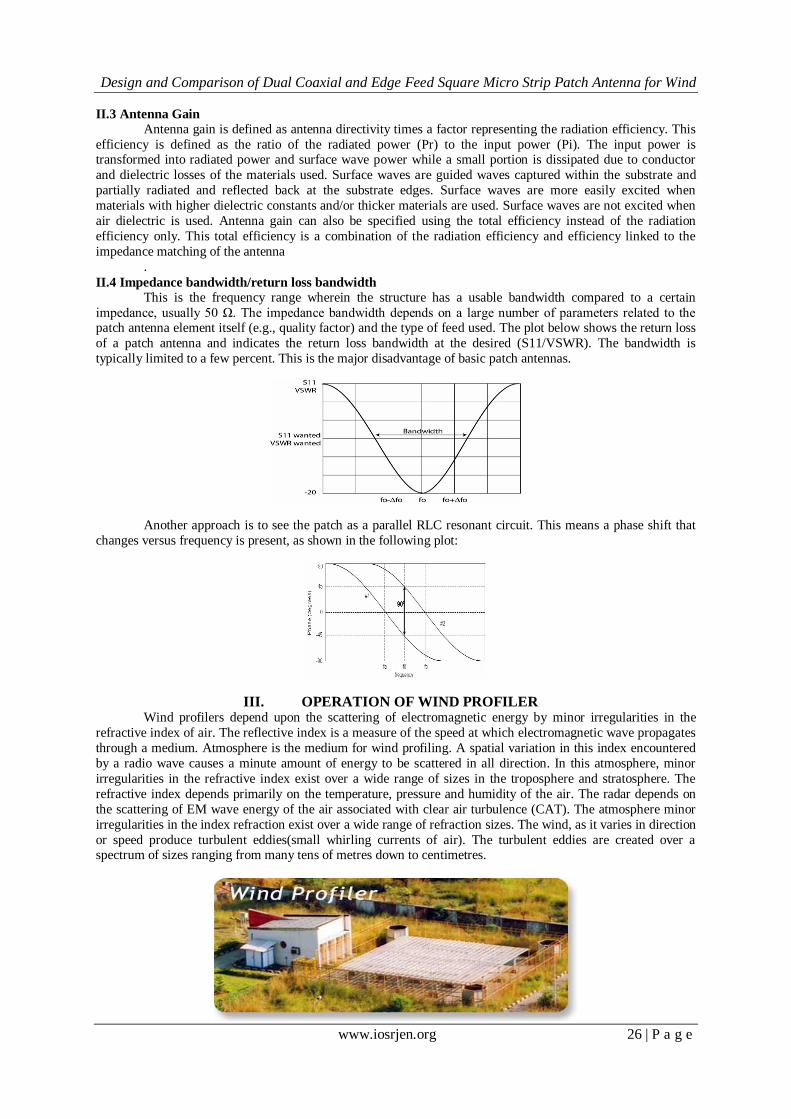
III. OPERATION OF WIND PROFILER
Wind profilers depend upon the scattering of electromagnetic energy by minor irregularities in the
refractive index of air. The reflective index is a measure of the speed at which electromagnetic wave propagates
through a medium. Atmosphere is the medium for wind profiling. A spatial variation in this index encountered
by a radio wave causes a minute amount of energy to be scattered in all direction. In this atmosphere, minor
irregularities in the refractive index exist over a wide range of sizes in the troposphere and stratosphere. The
refractive index depends primarily on the temperature, pressure and humidity of the air. The radar depends on
the scattering of EM wave energy of the air associated with clear air turbulence (CAT). The atmosphere minor
irregularities in the index refraction exist over a wide range of refraction sizes. The wind, as it varies in direction
or speed produce turbulent eddies(small whirling currents of air). The turbulent eddies are created over a spectrum of sizes ranging from many tens of metres down to centimetres.
Design and Comparison of Dual Coaxial and Edge Feed Square Micro Strip Patch Antenna for Wind
www.iosrjen.org 27 | P a g e
Wind profiler radars are vertically directed pulsed Doppler radars capable of analysing the back-
scattered signals to determine the velocity of air along the beams. By steering the beams typically 15° from
zenith, the horizontal and vertical components of the air motion can be obtained. Radar systems for weather forecasting purposes are to be accommodated in the frequency allocations of the radiolocation service and/or the
meteorological aids service. Existing uses in these bands need to be protected and compatibility with the
services in the adjacent bands has to be assured. On the other hand, accommodation in the frequency bands of
other radio services could be considered, if this is acceptable from a frequency-sharing point of view. For the
identification of the various compatibility and/or sharing options, a clear understanding of the concept of wind
profiler radar systems and their behaviour in the electromagnetic environment is needed. The important
applications of a conventional Wind Profile Radar lies in (i) Short range forecasting, (ii) Convective storm
initiation, (iii) Climates, (iv) Air Pollution, (v) Aviation operations and flight planning, and (vi) Rocket and
missile launching etc.
IV. FEEDING TECHNIQUES
Microstrip line feed is one of the easier methods to fabricate as it is a just conducting strip connecting
to the patch and therefore can be consider as extension of patch. It is simple to model and easy to match by
controlling the inset position. The disadvantage of this method is that as substrate thickness increases,
surface wave and spurious feed radiation increases which limit the bandwidth. In Coaxial feeding, the inner
conductor of the coaxial is attached to the radiation patch of the antenna while the outer conductor is connected
to the ground plane. The main advantages of this method are easy to fabricate, easy to match and low spurious
radiation. Aperture coupling consist of two different substrate separated by a ground plane. On the bottom side
of lower substrate there is a microstip feed line whose energy is coupled to the patch through a slot on the
ground plane separating two substrates. Top substrate uses a thick low dielectric constant substrate, and the
bottom substrate uses high dielectric substrate. The ground plane, which is in the middle, isolates the feed from radiation element and minimizes interference of spurious radiation for pattern formation and polarization. The
main advantage of this method is allows independent of feed mechanism element. Proximity coupling has the
largest bandwidth, has low spurious radiation. Length of feeding stub and width-to-length ratio of patch is used
to match.
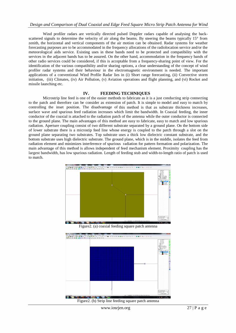
Figure2. (a) coaxial feeding square patch antenna
Figure2. (b) Strip line feeding square patch antenna

Design and Comparison of Dual Coaxial and Edge Feed Square Micro Strip Patch Antenna for Wind
www.iosrjen.org 28 | P a g e
Figure (a) shows the coaxial feeding microstrip square patch antenna and Figure (b) shows the strip
line feeding microstrip square patch antenna. Both these antennas are using RT-Duroid substrate material of
dielectric constant 2.2.
V. OVERVIEW OF IE3D SOFTWARE
IE3D is a full wave, method of moments (MOM) based electromagnetic simulator for analyzing and
optimizing planar and 3D structures in a multi-layer dielectric environment. It solves Maxwell's equation in
integral form and its solutions include the wave effects, discontinuity effects, coupling effects and radiation
effects. The simulated result includes S,Y, and Z-parameters, VSWR, RLC equivalent circuits, current field
distribution, near and far field estimation, radiation pattern etc.
IE3D is an extremely useful tool in the design of MMICs, RFICs, RF printed circuits, Micro strip and wired RF
Antennas, multilayer PCBs and IC interconnections.
V.1 The important features of Zeland Software, Inc. IE3D Version 12:
(a) IE3D Fast EM Design Kit for real-time full-wave EM tuning, optimization and synthesis.
(b) Multi-fold speed improvement and multi-CPU support for much improved efficiency.
(c) Equation-based schematic-layout editor with Boolean operations for easy and flexible geometry editing and
parameterization.
(d) Lumped element equivalent circuit automatic extraction and optimization for convenient circuit designs.
(e) Improved integration into Microwave Office from Applied Wave Research
.
V.2 Applications of IE3D:
(a) RF circuits, LTCC circuits and RF ICs. (b) Microwave, RF and wireless antennas.
(c) RFID tag antennas.
(d) HTS filters.
(e) Electronic packaging and signal integrity.
(f) Microwave circuits and MMICs.
(g) Many other low to high frequency structures.
V.3 Applications of IE3D in Antennas:
(a) Planar antennas such as micro strip antennas and slot antennas.
(b) Wire antennas such as various types of dipole, monopole, helix and quadrifilar antennas.
(c) Small antennas such as inverted-F antennas and its derivations.
(d) Dielectric resonator antennas. (e) RFID antennas.
(f) Optical frequency antennas.
(g) Many other types of antennas.
VI. DESIGN OF A RECTANGULAR MICRO STRIP PATCH ANTENNA In this paper, selected parameters are: Resonant Frequency = 430 MHz, Dielectric material is RT-
DUROID5880, Dielectric constant €r = 2.2, Height of the dielectric substrate h = 3.175 mm, tan ∂ = 0.0009.
Patch Length = Width = 235.7mm. Feed Length = 58.92mm.,Feed width = 0.86mm.(for strip line).
VII. SIMULATED RESULT FOR DIFFERENT PARAMETERS
Fig. 3(a): Return Loss vs frequency plot in Coaxial feeding antenna
Design and Comparison of Dual Coaxial and Edge Feed Square Micro Strip Patch Antenna for Wind
www.iosrjen.org 29 | P a g e
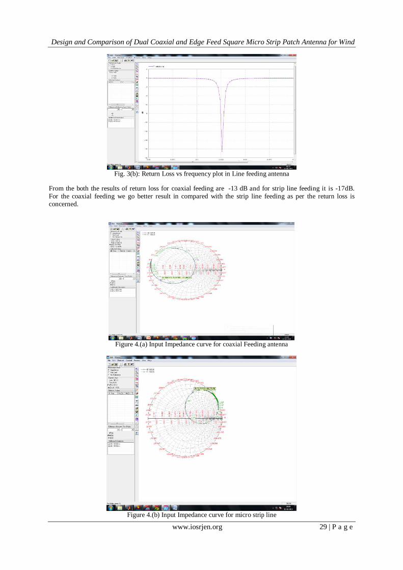
Fig. 3(b): Return Loss vs frequency plot in Line feeding antenna
From the both the results of return loss for coaxial feeding are -13 dB and for strip line feeding it is -17dB.
For the coaxial feeding we go better result in compared with the strip line feeding as per the return loss is
concerned.
Figure 4.(a) Input Impedance curve for coaxial Feeding antenna
Figure 4.(b) Input Impedance curve for micro strip line
Design and Comparison of Dual Coaxial and Edge Feed Square Micro Strip Patch Antenna for Wind
www.iosrjen.org 30 | P a g e
Feeding antenna
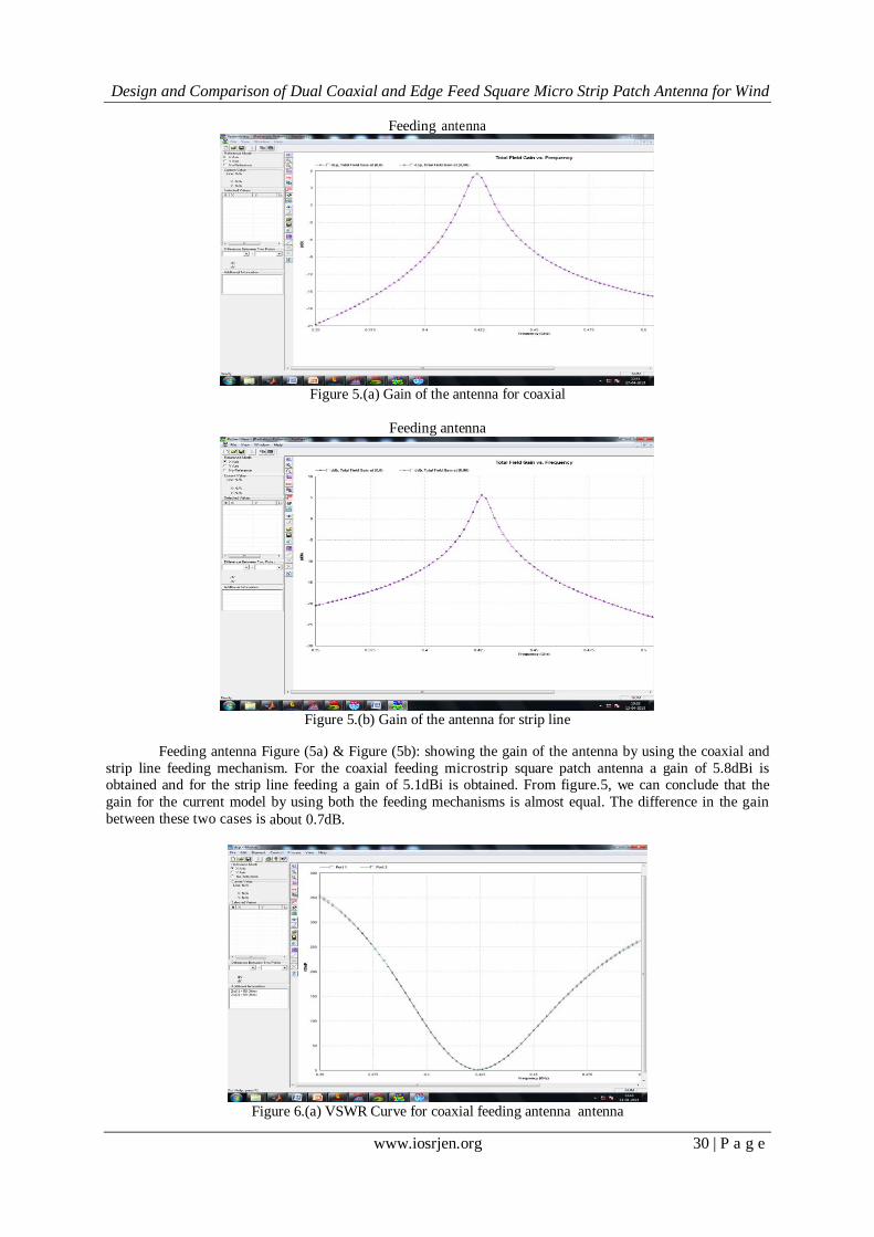
Figure 5.(a) Gain of the antenna for coaxial
Feeding antenna
Figure 5.(b) Gain of the antenna for strip line
Feeding antenna Figure (5a) & Figure (5b): showing the gain of the antenna by using the coaxial and
strip line feeding mechanism. For the coaxial feeding microstrip square patch antenna a gain of 5.8dBi is obtained and for the strip line feeding a gain of 5.1dBi is obtained. From figure.5, we can conclude that the
gain for the current model by using both the feeding mechanisms is almost equal. The difference in the gain
between these two cases is about 0.7dB.
Figure 6.(a) VSWR Curve for coaxial feeding antenna antenna

Design and Comparison of Dual Coaxial and Edge Feed Square Micro Strip Patch Antenna for Wind
www.iosrjen.org 31 | P a g e
Figure 6.(b) VSWR Curve for strip line feeding antenna
Figure (8a) and figure (8b) giving the VSWR curve Vs frequency for both the feeding techniques.
The VSWR obtained from the coaxial fed square patch antenna is about 1.214 and for the strip line fed antenna
the VSWR is 1.21 at 0.425GHz. Both these values are maintaining the standardization with 2:1VSWR ratio.
Figure 7.(a) 3D Radiation pattern for coaxial feeding antenna
Figure 7.(b) 3D Radiation pattern for micro strip line feed

Design and Comparison of Dual Coaxial and Edge Feed Square Micro Strip Patch Antenna for Wind
www.iosrjen.org 32 | P a g e
Figfigure 7.(a) and figure 7.(b) are giving the radiation pattern in theta direction for both the cases in
three dimensional views. From these two figures we observed that the radiation pattern is broader in both
directions and the radiation efficiency is acceptable for the entire region.
Figure 8.(a) Antenna and Radiation efficiency for coaxial feeding antenna
Figure 8.(b) Antenna and Radiation efficiency for strip line feeding antenna
Figure 8.(a) and figure 8.(b) giving the efficiency curve Vs frequency for both the feeding
techniques. The Antenna And Radiation efficiency obtained from the coaxial feed square patch antenna is about
65% and 68% and for the strip line feed antenna the Antenna And Radiation efficiency is 66% and 63%.
VIII. CONCLUSION
The Research motivation of this project is to design Square Micmicrostrip patch antenna for
atmospheric Wind Profile Radar application which operates in C-band at 5 GHz. IE3D electromagnetic simulator is used for design and simulation of patch Antenna. The rectangular patch antenna with 50ohms line
feed has been designed. The proposed square patch antenna is designed by considering coaxial feeding and strip
line feeding and their output parameters are presented in this paper. In both the cases the results showing
the good impedance matching between the input and the output. The gains obtained from these cases
are 7.4dBi and 7.25dBi respectively for coaxial feeding and strip line feeding. The return loss obtained from
these cases are -25dBi and -21dBi respectively for coaxial feeding and strip line feeding. The Antenna and
Radiation efficiency for coaxial feed patch antenna is 92% and 91% and for the strip line feed antenna the
Antenna and Radiation efficiency is 84% and 83%. The strip line feeding is preferable because of impedance
mismatching with the case of coaxial feeding. Coaxial feeding requires number of trial and error
methods for getting impedance bandwidth perfectly. Whereas for the strip line feeding impedance related
problems can be almost avoided.

Design and Comparison of Dual Coaxial and Edge Feed Square Micro Strip Patch Antenna for Wind
www.iosrjen.org 33 | P a g e
IX. ACKNOWLEDGMENT The authors of this paper would like to acknowledge all the corresponding IEEE paper holders and
most importantly the publishers of related books and journals which gave immense support and inspiration in
eparing this manuscript. Above all, the extreme mental support and source of inspiration from all the family
members and friends are widely acknowledged.
REFERENCES [1]. Srinivasulu. P, Manas R Padhy, Yasodha. P and NarayanaRao. T, 2010 “Development of UHF wind
profiling radar for lower atmospheric research applications”. Conference paper at NARL. [2]. Srinivasulu. P, Yasodha. P, Rajendra Prasad. T and Narayana Reddy. S 2010 “Development of
1280 MHz Active Array RADAR at NARL”. Conference Paper at NARL DRAWS-2010.
[3]. C.T.P.Song, P.S.Hall and H.G.Shiraz, “Multiband Multiple Ring Monopole Antennas” IEEE Trans. on
Antennas and propagation, vol. 51,No.4 pp. 722–729, April. 2003.
[4]. Karaboga, D., K. Guney, S. Sagiroglu, and M. Erler, \Neural computation of resonant frequency of
electrically thin and thick rectangular microstrip antennas," IEEE Proceedings | Microwaves, Antennas
and Propagation, Vol. 146, No. 2, 155{159, Apr. 1999.
[5]. Mishra, R. K. and A. Patnaik, \Neural network-based CAD model for the design of square-patch
antennas," IEEE Trans. on Antennas Propagat., Vol. 46, No. 12, 1890{1891, Dec. 1998.
[6]. Patnaik, A., R. K. Mishra, G. K. Patra, and S. K. Dash, \An arti¯cial neural network model for e®ective
dielectric constant of microstrip line," IEEE Trans. on Antennas Propagat., Vol. 45, No. 11, 1697, Nov.
1997. [7]. R. G. Voughan. 1988. Two-port higher mode circular microstrip antennas. IEEE, Trans. Antennas
Propagat.36(3): 309-321.
[8]. D.D.Sandu, O.Avadanei, A.Ioachima, G.Banciua, P.Gasner. Microstrip Patch Antenna with
dielectric substrate. Journal Optoelectronics and Advanced Materials Vol. 5, No. 5, 2003.
AUTHORS’ INFORMATION DEBAJYOTI CHATTERJEE is currently pursuing M.Tech in RF & Microwave Engineering from the Department of Electronics and Communication, GIT, GITAM University, Visakhapatnam, A.P, India. Presently he is carrying out his project work on Microstrip Patch Antenna Design from National Atmospheric Research Laboratory (NARL), Department of Space, Govt.of India. He has completed his M.Sc in Electronics and Communication from School of Electronics, Devi Ahilya University, M.P, and
India. He has achieved his B.Sc degree in Electronics (H) from University of Calcutta, West Bengal, India. He has published three International Journals and presented one research paper in a National Conference.
DR. P.V.Y JAYASREE is Associate Professor in the Department of ECE, GITAM Institute
of Technology, GITAM University Visakhapatnam, A.P, India. She is the course coordinator
for M.Tech (RF & Microwave Engg.) branch. Her area of specialisation is Antenna and
Electromagnetism.
Dr. P. SRINIV ASUL U is presently working as Scientist-SF at National Atmospheric
Research Laboratory (NARL),Department of Space,Govt.of India. He is involved in the
installation a n d c o m m i s s i o n i n g of the VHF Indian MST Radar and L -band
B o u n d a r y Layer Radar a t NARL. He has expertise on high power radar transmitters,
phased antenna a r r a y s and receivers. Currently he i s working on leading active array
radar projects in VHF and UHF bands for atmospheric remote sensing application.