
Design and Analysis of Vertical Industrial Pump Casing · PDF fileDesign and Analysis of...
8
International Research Journal of Engineering and Technology (IRJET) e-ISSN: 2395-0056 Volume: 04 Issue: 09 | Sep -2017 www.irjet.net p-ISSN: 2395-0072 Design and Analysis of Vertical Industrial Pump Casing Stand Mr. Ashish Dudhale 1 , Prof. P.P. Ritapure 2 1 PG Scholar, Dept. of Mechanical Engineering, ZES 'Zeal College of engineering & Research, Maharashtra, India 2 Professor, Dept. of Mechanical Engineering, ZES 'Zeal College of engineering & Research, Maharashtra, India ---------------------------------------------------------------------***--------------------------------------------------------------------- Abstract - This paper discusses about static and dynamic analysis of vertical turbine pump. Integrated product customization mode in design of product is very known field in OEM industries. Here vertical hydraulic pump is considered for up gradation and optimization. Existing model is heavy structure and inconvenient from maintenance point of view. It is to be modified with external body replacement. So bottom case is to be made up of sheet metal and rod/bracket component which will act as a stand and will sustain all the loads coming from the pump. Manufacturing cost with simplicity in design optimization will take effect here. New product will be designed with its aesthetic terms and mechanical strengthening. Validation of structural stand will be carried out experimentally as well as CAE modes by examining boundary conditions. Key Words: Casing Stand, FEA, FFT Analyzer, Modal Analysis, Vertical Turbine Pump (VTP). 1.INTRODUCTION Generally the Pump Support Stand is cast iron with vinyl pads on the feet to eliminate damaging the basin floor. The stand can be used with the 2 HP or equivalent motor pumps which supports the pump at the required distance from the basin floor. We are having task to design dedicated stand structure which can be mechanically proven for use of pump and its loading conditions to sustain. Vertical stand is to be made for 2 HP pump. Pump is specially designed for industrial use like water supply. Chemical supply, cleaning and dewatering machines, oil sectors etc. In current stage pump is in design stage and typically if we see, the pump stand is made up of casting material and sheet metal support tightened by threading bolting techniques. We are optimizing the things to design a perfect light weight solution for mounting of hub holding a pump motor vertically on top of the pump assembly. Generally outer casing is very heavy in conventional pumps; we are trying to reduce the size and shape of the pump along with cost optimization. The pump under study is of Grundfos CRNE Series which is used with press control for constant water pressure and dry running in case of no water in the pipeline. Advantages: Simple in operation, Low initial and maintenance cost, less excessive pressure build up in casing, Impeller and shaft are the only moving parts, Quiet operations, Wide range of pressure, flow and capacities, Utilize small floor space in different positions. Disadvantages: Poor handling of viscous fluids, not capable of handling high pressure applications in comparison to other types of pumps, i.e., Regenerative turbines. In general, Centrifugal pumps cannot deliver high pressure without changes in design and are not suitable for high pressure delivery at low volumes except the multistage pumps. 2. LITERATURE REVIEW Literature on the vertical pump casing and stand has been reviewed. Most of the available literature is for the horizontal systems. There is very little amount of information available regarding the vertical arrangement systems such as a vertical pump. Michael Singer and Torsten Johne[1]recommended different pump casing design techniques. They did a comparison of various techniques and gave design checks for vertical centrifugal pump. They stated that currently, there is no existing code or standard particular to the design of centrifugal pump casings. Their paper discusses about various types of failures and their respective test procedures. Main failures about casing and stand are: Buckling- It refers to structural instability under compressive loading. Kishor K. Meher and A.Rama Rao[2] said the main excitation to the assembly is caused by rotational speed and its harmonics during pump operation. This asks for careful design of the pump stand to keep the system separated from natural frequency and its multiples for trouble-free operation. Since little scope was observed for structural modification of the pump-motor unit, it was better to design the foundation structure. They made an attempt for the design of a foundation structure using FEA for a typical vertical pump to be installed in a research facility in BARC, Mumbai. They also stated that the support foundation design is based on the static weight of the pump-motor unit only without accounting for the dynamics of the complete assembly. In case of excessive vibration, we conduct a modal test on the pump assembly at site to diagnose the root cause and take appropriate corrective measures. Such a practice is generally difficult. © 2017, IRJET | Impact Factor value: 5.181 | ISO 9001:2008 Certified Journal | Page 1205
Transcript of Design and Analysis of Vertical Industrial Pump Casing · PDF fileDesign and Analysis of...

International Research Journal of Engineering and Technology (IRJET) e-ISSN: 2395-0056
Volume: 04 Issue: 09 | Sep -2017 www.irjet.net p-ISSN: 2395-0072
Design and Analysis of Vertical Industrial Pump Casing Stand
Mr. Ashish Dudhale1, Prof. P.P. Ritapure2
1PG Scholar, Dept. of Mechanical Engineering, ZES 'Zeal College of engineering & Research, Maharashtra, India 2Professor, Dept. of Mechanical Engineering, ZES 'Zeal College of engineering & Research, Maharashtra, India
---------------------------------------------------------------------***---------------------------------------------------------------------
Abstract - This paper discusses about static and dynamic analysis of vertical turbine pump. Integrated product customization mode in design of product is very known field in OEM industries. Here vertical hydraulic pump is considered for up gradation and optimization. Existing model is heavy structure and inconvenient from maintenance point of view. It is to be modified with external body replacement. So bottom case is to be made up of sheet metal and rod/bracket component which will act as a stand and will sustain all the loads coming from the pump. Manufacturing cost with simplicity in design optimization will take effect here. New product will be designed with its aesthetic terms and mechanical strengthening. Validation of structural stand will be carried out experimentally as well as CAE modes by examining boundary conditions. Key Words: Casing Stand, FEA, FFT Analyzer, Modal Analysis, Vertical Turbine Pump (VTP).
1.INTRODUCTION Generally the Pump Support Stand is cast iron with vinyl pads on the feet to eliminate damaging the basin floor. The stand can be used with the 2 HP or equivalent motor pumps which supports the pump at the required distance from the basin floor. We are having task to design dedicated stand structure which can be mechanically proven for use of pump and its loading conditions to sustain. Vertical stand is to be made for 2 HP pump. Pump is specially designed for industrial use like water supply. Chemical supply, cleaning and dewatering machines, oil sectors etc. In current stage pump is in design stage and typically if we see, the pump stand is made up of casting material and sheet metal support tightened by threading bolting techniques. We are optimizing the things to design a perfect light weight solution for mounting of hub holding a pump motor vertically on top of the pump assembly. Generally outer casing is very heavy in conventional pumps; we are trying to reduce the size and shape of the pump along with cost optimization. The pump under study is of Grundfos CRNE Series which is used with press control for constant water pressure and dry running in case of no water in the pipeline.
Advantages: Simple in operation, Low initial and maintenance cost, less excessive pressure build up in casing, Impeller and shaft are the only moving parts, Quiet operations, Wide range of pressure, flow and capacities, Utilize small floor space in different positions. Disadvantages: Poor handling of viscous fluids, not capable of handling high pressure applications in comparison to other types of pumps, i.e., Regenerative turbines. In general, Centrifugal pumps cannot deliver high pressure without changes in design and are not suitable for high pressure delivery at low volumes except the multistage pumps.
2. LITERATURE REVIEW Literature on the vertical pump casing and stand has been reviewed. Most of the available literature is for the horizontal systems. There is very little amount of information available regarding the vertical arrangement systems such as a vertical pump. Michael Singer and Torsten Johne[1]recommended different pump casing design techniques. They did a comparison of various techniques and gave design checks for vertical centrifugal pump. They stated that currently, there is no existing code or standard particular to the design of centrifugal pump casings. Their paper discusses about various types of failures and their respective test procedures. Main failures about casing and stand are: Buckling- It refers to structural instability under compressive loading. Kishor K. Meher and A.Rama Rao[2] said the main excitation to the assembly is caused by rotational speed and its harmonics during pump operation. This asks for careful design of the pump stand to keep the system separated from natural frequency and its multiples for trouble-free operation. Since little scope was observed for structural modification of the pump-motor unit, it was better to design the foundation structure. They made an attempt for the design of a foundation structure using FEA for a typical vertical pump to be installed in a research facility in BARC, Mumbai. They also stated that the support foundation design is based on the static weight of the pump-motor unit only without accounting for the dynamics of the complete assembly. In case of excessive vibration, we conduct a modal test on the pump assembly at site to diagnose the root cause and take appropriate corrective measures. Such a practice is generally difficult.
© 2017, IRJET | Impact Factor value: 5.181 | ISO 9001:2008 Certified Journal | Page 1205

International Research Journal of Engineering and Technology (IRJET) e-ISSN: 2395-0056
Volume: 04 Issue: 09 | Sep -2017 www.irjet.net p-ISSN: 2395-0072
Robert F. Strohs[3] designed a work stand specially designed for supporting and aligning the various components of a vertical turbine pump during assembly or disassembly. This work stand was for vertical pump but has an arrangement in horizontal direction with cradle support and heavy structure. D.S. Chawla, R.S. Soni, H.S. Kushwaha[4] presented regarding assessment of structural integrity and operability of VTP motor units for a typical PHWR. Their work was on stability of vertical pump for seismic event like a safe shutdown earthquake. They observed that the contribution of seismic loading towards the total deflection was very less. Their FEA of the pump casing with the pump stool showed that the stresses in various parts are well within the limits and thereby ensure the structural integrity of the unit. Shahram Shahrooi, Ibrahim Henk Metselaar, Zainul Huda, Masood Asayesh[5]studied different cases for reducing the amount of vibration. The effect of each decision considered in model and analysis again had been done with the same boundary condition. The modification cases and their results were as follows: The first recommendation was improvement in base plate stiffening. The second solution for vibration problem of system is reinforcing the shaft casing. Stiffening of shaft casing has the same effects of base plate stiffing. The final solution that was considered for improvement of vibration behavior of the system was simultaneously stiffening of casing near the impeller and base plate. Jyoti K. Sinha, A. Rama Rao[6]discussed about the frequent failure of bearing. They used vibration based conventional condition monitoring to identify the progressive nature of the bearing failure, but failed to identify the root cause. They conducted modal tests on the pump assembly to understand the dynamics of the complete assembly. A typical case of the resonance of the bearing pedestals during pump operation mainly due to nonlinear interaction between the pump foundation and the concrete floor. They concluded it can be solved either by stiffening the roots of bearing pedestals and properly grouting the base plate in concrete or by increasing the gap between the plate and concrete to avoid interaction. Ramana Podugu, J.Suresh Kumar, B.V.Ramana murthy, N.Syam Kumar[7] performed modal analysis of the centrifugal pump and its assembly using FEM technology. The mathematical and FEA model were built and simulation was performed to find the pump natural frequencies. The first ten natural frequencies were compared to pump operating speed and their multiples as per HIS (Hydraulic Institute Standards -9.6.4-2000) guidelines. They found natural frequency close to operating speed and suggested to stiffen the foundation base and found that after stiffening, the natural frequency 10%more than the operating speed. Khaled Fetyan, Dalia El Gazzar[8]studied the effect of motor vibration problems on the dynamic performance and electrical power quality of water pumping stations is studied.
The dynamic results indicated that the motor base plate is loose. After achieving good support to the motor on its base plate, the measurements were repeated again. The results indicated that the vibration level decreased and it was about 48% due to good support/foundation. Bill Beekman[9] has worked in vertical pump industry and discussed the influence of excessive resonance and how it can be dealt with. He advised to provide a foundation that represents less than 5% of the total deflection of the structural elements of the pump/drive. A reinforced concrete foundation will work out with these criteria. If the natural frequency is close to the maximum rpm, the unit can be stiffened and it will be more robust. However, there is a limit to the pump manufacturer’s ability to add rigidity and obtaining a vertical motor that has a high level of rigidity may not be feasible. M.M. Osman[10] did a case study on reduction in vibration of vertical pump. He attributed vibration problem in vertical pump due to their one point attachment to the foundation. The fact that vertical pumps exhibit usually higher vibration levels than that of horizontal pumps can be partially attributed to how they are mounted. Vertical pumps are typically attached to the foundation at one point only, normally at ground level, thus creating a cantilever effect above and below the attaching point. Moreover, pump base has to support the driving motor weight. It seems that vibrations below pump base are not noted by the user nor do they tend to damage the pump set, but that of components above foundation level are of concern, specifically motor top which is the uppermost component. For reduction in vibration a flexible plate, made of steel, was introduced between the pump head and the motor. The use of a flexible plate, introduced between a vertical pump head and the driving motor, has produced an appreciable reduction in motor top vibration levels.
3. EXISTING SYSTEM & OBJECTIVES Vertical stand with metal covering body is very bulky and non-repairable from maintenance point of view. Also on casting base frame if bolted joint is failed with threads, putting new threads is again problematic and wall thickness problem arises. Sheet metal covering with welded joints are not found compatible as a pump casing stand from geometrical point of view so new product development is to be considered in new design.
Fig -1: Existing System and its Failure.
© 2017, IRJET | Impact Factor value: 5.181 | ISO 9001:2008 Certified Journal | Page 1206

International Research Journal of Engineering and Technology (IRJET) e-ISSN: 2395-0056
Volume: 04 Issue: 09 | Sep -2017 www.irjet.net p-ISSN: 2395-0072
4. DESIGN IMPLEMENTATION All the parts are drawn using CATIA (modeling software). Files are further converted into .step or .igs format for further analysis.
Fig -2: Standard Base Frame.
Fig -3: Standard Pump Motor.
A. Stand using Rod Element concept- Installation area for pump stand component on base frame is 211mm ×211mm. So PCD is taken as 210mm over which rod elements will be mounted in order to support pump motor coaxially.
Fig -4: Rod Element.
Fig -5: Rod and Base Frame Assembly.
Holes on base frame are found feasible to bore and tapping but there is an issue with wall thickness on base frame material boundaries. Hence idea of having 4 rod elements with sheet metal covering was dropped and new sheet metal angle with welded L shaped metal plates was carried out. B. Metal angle with L shaped plate concept- Static Load= Motor Load + Spool Impeller holder assembly+ Intermediate housing = 31Kg + 27.3Kg + 4.2Kg = 62.5Kg i.e. 625N This static load is taken by two L shaped columns with metal strips. So each bracket will bear 312.5N load.
Fig -6: Sheet Metal Support and L-Stand Angle.
Fig -7: Base frame with L-support and Final Design.
Buckling of columns- Columns / Struts are failed by buckling when their critical load is reached. They can be analyzed with the Euler column formula given below:
Where, Wcr = Allowable load (N) n = Factor of end conditions E = Modulus of Elasticity (MPa) L = Length of column (mm) I = Moment of inertia (mm) By taking n=4 as per end conditions, E=193 x 103 N/mm2, total I= 9550.13 mm4 and L=427mm; Euler’s load is coming out to be Wcr=WE= 398903.91 N.
© 2017, IRJET | Impact Factor value: 5.181 | ISO 9001:2008 Certified Journal | Page 1207
International Research Journal of Engineering and Technology (IRJET) e-ISSN: 2395-0056
Volume: 04 Issue: 09 | Sep -2017 www.irjet.net p-ISSN: 2395-0072
According to Rankin’s formula, crippling load is given by,
Where, Wcr = crippling load or buckling load Wc = ultimate crushing load of column material = σc × A (σc = ultimate crushing stress) = 320 × 287.625= 89163.75 N WE = Euler’s load= 398903.91 N So, Crippling load coming is equal to 72,874.66 N Component allows to take this much load.
Table -1: Comparison between Theories
Theory Value Johnson's equation 56,840.45 N Euler's equation 3,98,903.91 N Rankin Gordon 72,874.66 N
The load acting on the strut is approximate 312.5 N which is very less than crippling or buckling load. The maximum buckling stress is σcr = Wcr/A = 187 N/mm2 Actual stress for 312.5N is 312.5 / 287.625= 1.0864 MPa (Safe) Weld structure design-
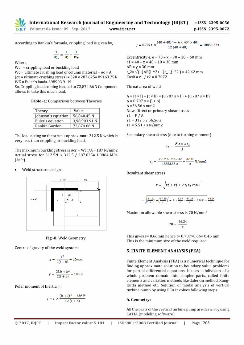
Fig -8: Weld Geometry.
Centre of gravity of the weld system:
Polar moment of Inertia, J :
Eccentricity e, e = 70 – x = 70 – 10 = 60 mm r1 = 40 – x = 40 – 10 = 30 mm AB = y = 30 mm r_2= √(〖AB〗^2+ 〖r_1〗^2 ) = 42.42 mm Cosθ = r1 / r2 = 0.7072 Throat area of weld- A = (t × l) + (t × b) = (0.707 s × l ) + (0.707 s × b) A = 0.707 s × (l + b) A =56.56 s mm2 Now, Direct or primary shear stress τ1 = P / A τ1 = 312.5 / 56.56 s τ1 = 5.51 / s N/mm2 Secondary shear stress (due to turning moment)
Resultant shear stress
Maximum allowable shear stress is 70 N/mm2
This gives s= 0.66mm hence t= 0.707×0.66= 0.46 mm This is the minimum size of the weld required.
5. FINITE ELEMENT ANALYSIS (FEA) Finite Element Analysis (FEA) is a numerical technique for finding approximate solution to boundary value problems for partial differential equations. It uses subdivision of a whole problem domain into simpler parts, called finite elements and variation methods like Galerkin method, Rung-Kutta method etc. Solution of modal analysis of vertical turbine pump by using FEA involves following steps. A. Geometry: All the parts of the vertical turbine pump are drawn by using CATIA (modeling software).
© 2017, IRJET | Impact Factor value: 5.181 | ISO 9001:2008 Certified Journal | Page 1208
International Research Journal of Engineering and Technology (IRJET) e-ISSN: 2395-0056
Volume: 04 Issue: 09 | Sep -2017 www.irjet.net p-ISSN: 2395-0072
B. Meshing: After the importation of the geometry, material properties are assigned. Material properties like density in kg/m3, Poisson's ratio, young's modulus in Pascal are assigned to different parts of the vertical turbine pump. After assigning material properties, geometry is divided into numbers of finite elements. The process of subdivision of domain into finite elements called as Discretization process also known as meshing. Model is meshed with triangular and rectangular elements. Meshing is used to get accurate results.
Fig -9: Assembly of VTP & Meshed Part.
C. Simulation: In the simulation process, initial conditions are given to pump. In this, fixing of the bottom of bracket is given as the initial condition as it is placed on the base frame. After that geometry is going under process to get solution and results. No hydrostatic pressure is found here as this pump is having inlet and outlet at base part.
Fig -10: Simulation of Bracket.
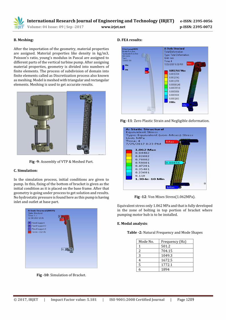
D. FEA results:
Fig -11: Zero Plastic Strain and Negligible deformation.
Fig -12: Von Mises Stress(1.062MPa).
Equivalent stress only 1.062 MPa and that is fully developed in the zone of bolting in top portion of bracket where pumping motor hub is to be installed. E. Modal analysis:
Table -2: Natural Frequency and Mode Shapes
Mode No. Frequency (Hz) 1 501.2 2 704.15 3 1049.3 4 1672.5 5 1772.1 6 1894
© 2017, IRJET | Impact Factor value: 5.181 | ISO 9001:2008 Certified Journal | Page 1209

International Research Journal of Engineering and Technology (IRJET) e-ISSN: 2395-0056
Volume: 04 Issue: 09 | Sep -2017 www.irjet.net p-ISSN: 2395-0072
Fig -13: Natural Frequency of Stand (501.2Hz).
6. EXPERIMENTAL VALIDATION A. Stress Validation using uniaxial strain gauge analogger: There are two types of strain gauges : Uniaxial and Strain Rosette. Uniaxial only measures one directional stress. It is used for uniaxial loading or for direction stress measurement. Strain Rosette measures principle stress. It is used for multiaxial loading. Multiple strain gauges are arranged in 45,60 and 90 degrees.
Fig -14: Strain gauge mounted on component with fixture.
Figure 14 represents actual mounting of stand bracket with suitable fixtures on test machine. It also shows locations where strain gauges are mounted. Strain gauges are preferably mounted on minimum, medium and maximum stress location area obtained from FE Analysis. This is the embedded system in which after loading, strain value is displayed on display board. By using hydro-pneumatic bar we have to apply force on support element. The display shows that the value of strain developed into support element. After getting strain readings, by using calculation method we find out stress value.
Table -3: Stress values
No. Micro-Strain Stress (MPa) 1 0.5 0.0965 2 0.5 0.0965 3 1.4 0.2702 4 1.5 0.2895 5 4 0.772 6 4.5 0.8685 7 4.5 0.8685 8 5.5 1.0615
B. FFT Analyzer test Impact testing is conducted using two/multiple channel FFT spectrum analyzer, a micro computer with special software, a set of vibration response probes such as accelerometer, and an impact hammer designed to spread force over a frequency range that covers the test range.
Fig -15: 8 channel FFT Analyzer.
Fig -16: Actual Test Setup.
© 2017, IRJET | Impact Factor value: 5.181 | ISO 9001:2008 Certified Journal | Page 1210

International Research Journal of Engineering and Technology (IRJET) e-ISSN: 2395-0056
Volume: 04 Issue: 09 | Sep -2017 www.irjet.net p-ISSN: 2395-0072
Fig -17: Test Result 1.
Fig -17: Test Result 2. Figure 16 and 17 shows output from FFT analyzer. It is observed that first maximum peak of acceleration is at 522.5 Hz. So natural frequency observed is 522.5 Hz.
7. RESULT AND DISCUSSION In this work, new product development of vertical industrial pump casing stand is discussed. Initially, conventional method of structural stand is illustrated and why new development is necessary is discussed. Static and Dynamic analysis is done on new developed product on ANSYS 17.2 Workbench Student Version and experimentation is carried out on Customized Uniaxial Strain Gauge Analogger. Also natural frequency and mode shapes of stand element are calculated using modal analysis. Firstly feasibility of conventional method was tested which consist of four rod element with sheet metal covering. But as per constraint in current work, wall thickness near holes for rod element was not sufficient.
Table -4: Results Parameter Analytical FEA Experimental Stress (MPa) 1.0864 1.062 1.0615 Deformation (mm)
0.00240 0.00234 0.00234
Table 4 does comparison between analytical, FEA and experimental values of stress and deformation. Analytical value of stress is 1.0864MPa, FEA value of stress is 1.062MPa and experimental value of stress is 1.0615MPa. Percentage error is 2.24% and 2.30% in between analytical-FEA and analytical-Experimental values respectively. Analytical value of deformation is 0.00240mm, FEA value of deformation is 0.00234mm and experimental value of deformation is 0.00234mm. Percentage error in deformation is 2.5% in both between analytical-FEA and analytical-Experimental values. The values differs from analytical to FEA to experimental because of different assumptions made in theory, software boundary conditions and experimental setup.
8. CONCLUSIONS After conducting finite element analysis and experimental validation, following conclusions are drawn: 1. Designed bracket structure for mounting motor hub assembly is found very safe according to structural conditions. 2. No plastic strains are observed in stand bracket with given boundary conditions. 3. Maximum deformation is 0.002 mm which is negligible. 4. Maximum Von-Mises stress by analytical, FEA and Experimental is 1.0864, 1.062 and 1.0615 MPa respectively which is safe enough. The difference might be because of changes in boundary condition in FEA and assumption in calculation. 5. From modal analysis, natural frequency of stand bracket is calculated and it is 501 Hz and is well separated from operating frequency. 6. From experimentation natural frequency of stand is obtained 522.5 Hz which is in close agreement with the modal analysis value. 7. No resonance will be observed since operating frequency and natural frequency is different. 8. Conventional method of sheet metal casing was heavy with complex maintenance method. 9. First, we tried designing stand with 4 stud concept but due to input constraints getting standard wall thickness due to hole and coaxial alignment was not possible so we came up with the bracket stand concept. 10. There is a little scope for optimization but it needs to be crossed checked with effect on dynamic performance of whole assembly. 11. It was found feasible solution with negligible stresses and deformations. Also it is very easy from maintenance point of view.
© 2017, IRJET | Impact Factor value: 5.181 | ISO 9001:2008 Certified Journal | Page 1211

International Research Journal of Engineering and Technology (IRJET) e-ISSN: 2395-0056
Volume: 04 Issue: 09 | Sep -2017 www.irjet.net p-ISSN: 2395-0072
REFERENCES [1] Micheal Singer, Torsten Johne. Design of Pump Casings: Guidelines for a Systematic Evaluation of Centrifugal Pump Pressure Boundary Failure Modes and their Mechanisms.Proceedings of the Twenty-Ninth International Pump Users Symposium October 1-3, 2013, Houston, Texas.
[2] Kishor Meher. A.Rama Rao, Optimal foundation design of a vertical pump assembly.Journal of Sound and Vibration 291 (2006) 1269–1277.
[3] US4295257 A, (US), 20 February 1980, Work stand for vertical turbine pumps, 1981.
[4]D.S. Chawla, R.S. Soni, H.S. Kushwaha, Assessment of operability and structural integrity of a vertical pump for extreme loads.International Journal of Pressure Vessels and Piping 75 (1998) 297-306
[5] Shahram Shahrooi, Ibrahim Henk Metselaar, Zainul Huda, Masood Asayesh. Numerical and Experimental Vibration Analysis for Fatigue Failure Investigation in a Vertical Axis Pump Station. Proceedings of the International MultiConference of Engineers and Computer Scientists 2009 Vol II IMECS 2009, March 18 - 20, 2009, Hong Kong .
[6] Jyoti K. Sinha, A. Rama Rao, A Technical Note on Vibration Based Diagnosis of a Centrifugal Pump.Vibration Laboratory, Reactor Engineering Division, Bhabha Atomic Research Centre, Mumbai, India.
[7] Ramana Podugu, J.Suresh Kumar, B.V.Ramana murthy, N.Syam Kumar, A modal approach for vibration analysis and condition monitoring of a centrifugal pump, International Journal of Engineering Science and Technology (IJEST)
[8] Khaled Fetyan, Dalia El Gazzar, Effect of motor vibration problem on the power quality of water pumping stations, Water Science 28 (2014) 31–41.
[9] Bill Beekman, Resonant vibrations in vertical pumps, World PumpsVolume 2004, Issue 458, November 2004, Pages 18, 20–22
[10] M.M. Osman, vibration reduction of vertical pumps, a case history, Ontario HydroPower Equipment and Energy Studies Department.
BIOGRAPHIES
This author is PG Scholar of Department of Mechanical Design Engineering, ZES' Zeal College of Engineering & Research, Pune.
© 2017, IRJET | Impact Factor value: 5.181 | ISO 9001:2008 Certified Journal | Page 1212


