
Design and analysis of the ferrite air-gapped cores for a ...
11
ARCHIVES OF ELECTRICAL ENGINEERING VOL. 67(3), pp. 579–589 (2018) DOI 10.24425/123664 Design and analysis of the ferrite air-gapped cores for a resonant inductor JIANFEN ZHENG,CHUNFANG WANG,DONGWEI XIA College of Automation Engineering, Qingdao University Qingdao 266071, China e-mail: {jianfenzh/XDW}@qdu.edu.cn, [email protected] (Received: 02.03.2018, revised: 03.06.2018) Abstract: In this paper, a three-air-gapped structure of a ferrite core for a resonant inductor is proposed. The electromagnetic and thermal field models are built using a 3D finite element method. Compared with the conventional signal-air-gapped structure of a ferrite core, the simulation and analysis results show that the proposed three-air-gapped ferrite core resonant inductor can reduce eddy-current loss and decrease temperature rise. In addition, the optimal position of air-gapped is presented. Key words: three-air-gapped, electromagnetic and thermal field, finite element method, resonant inductor 1. Introduction In recent years, an inductance-inductance-capacitance (LLC) resonant converter is very attrac- tive topology for high-powerapplications because of its attractive features: smooth waveforms, high efficiency and high power density [1–4]. In the resonant inductors of the LLC converter, the current waveform includes the higher order harmonic components caused by switching. For this reason, excellent high frequency magnetic properties are necessary in iron core materials for use in high frequency inductors. Soft ferrites demonstrate properties such as low power loss and high permeability, which make them very useful and appropriate for use in power electric applications [5, 6]. The core loss evaluation was performed, and the influence of inductor gaps on iron loss was proposed in [7–9]. A simplified 2D model was presented to investigate influence of an air-gap in the magnetic field as describe in [10]. A 3D magnetic field is analyzed related to the solution of Laplace’s and Poisson’s equations by the finite element method [11]. In [12], a dynamic, nonlinear magnetic field analysis of a reactor core with air-gap was carried out. However, these studies, based on the finite element analysis, are directed at the study of the ferrite core, taking into account the single air-gapped core only. Eddy currents are induced in the air-gapped ferrite core due to fringing flux, and this causes local overheating. In order to reduce the eddy-current loss and decrease temperature rise, a three-air-gapped structure of a ferrite core
Transcript of Design and analysis of the ferrite air-gapped cores for a ...

ARCHIVES OF ELECTRICAL ENGINEERING VOL. 67(3), pp. 579–589 (2018)
DOI 10.24425/123664
Design and analysis of the ferrite air-gapped coresfor a resonant inductor
JIANFEN ZHENG, CHUNFANG WANG, DONGWEI XIA
College of Automation Engineering, Qingdao UniversityQingdao 266071, China
e-mail: {jianfenzh/XDW}@qdu.edu.cn, [email protected]
(Received: 02.03.2018, revised: 03.06.2018)
Abstract: In this paper, a three-air-gapped structure of a ferrite core for a resonant inductoris proposed. The electromagnetic and thermal field models are built using a 3D finiteelement method. Compared with the conventional signal-air-gapped structure of a ferritecore, the simulation and analysis results show that the proposed three-air-gapped ferrite coreresonant inductor can reduce eddy-current loss and decrease temperature rise. In addition,the optimal position of air-gapped is presented.Key words: three-air-gapped, electromagnetic and thermal field, finite element method,resonant inductor
1. Introduction
In recent years, an inductance-inductance-capacitance (LLC) resonant converter is very attrac-tive topology for high-power applications because of its attractive features: smooth waveforms,high efficiency and high power density [1–4]. In the resonant inductors of the LLC converter,the current waveform includes the higher order harmonic components caused by switching. Forthis reason, excellent high frequency magnetic properties are necessary in iron core materialsfor use in high frequency inductors. Soft ferrites demonstrate properties such as low power lossand high permeability, which make them very useful and appropriate for use in power electricapplications [5, 6]. The core loss evaluation was performed, and the influence of inductor gapson iron loss was proposed in [7–9]. A simplified 2D model was presented to investigate influenceof an air-gap in the magnetic field as describe in [10]. A 3D magnetic field is analyzed relatedto the solution of Laplace’s and Poisson’s equations by the finite element method [11]. In [12],a dynamic, nonlinear magnetic field analysis of a reactor core with air-gap was carried out.
However, these studies, based on the finite element analysis, are directed at the study of theferrite core, taking into account the single air-gapped core only. Eddy currents are induced in theair-gapped ferrite core due to fringing flux, and this causes local overheating. In order to reducethe eddy-current loss and decrease temperature rise, a three-air-gapped structure of a ferrite core

580 J. Zheng, C. Wang, D. Xia Arch. Elect. Eng.
for a resonant inductor is proposed in this paper. The resonant inductor of the LLC resonantconverter is shown in Fig. 1, which is applied in the battery-pile circuit of an electric car.
Fig. 1. Topology circuit of LLC resonant convertor
The electromagnetic and thermal field coupled model is built using a 3D finite elementmethod (FEM). Compared with the conventional single-air-gapped ferrite core, the simulatedresults indicate that the proposed three-air-gapped ferrite core can reduce eddy-current loss anddecrease temperature rise. In addition, it is presented for a three-air-gapped optimal curve and theoptimum placement.
2. Proposed structure of ferrite core inductor
Fig. 2 shows the model inductor used for simulation and analysis.
Fig. 2. Resonant inductor of LLCresonant convertor
A dual-E magnetic core with a single-air-gap is generally used as magnetic core of a resonantinductor. The single-air-gapped ferrite core structure is shown in Fig. 3(a). As it is known to all,eddy currents are induced in a magnetic core due to the leakage of magnetic flux, which cancause local overheating. In order to reduce local eddy current loss and avoid local heating, athree-air-gapped structure of a ferrite core is proposed, as shown in Fig. 3(b).
Vol. 67 (2018) Design and analysis of the ferrite air-gapped cores for a resonant inductor 581
(a) (b)
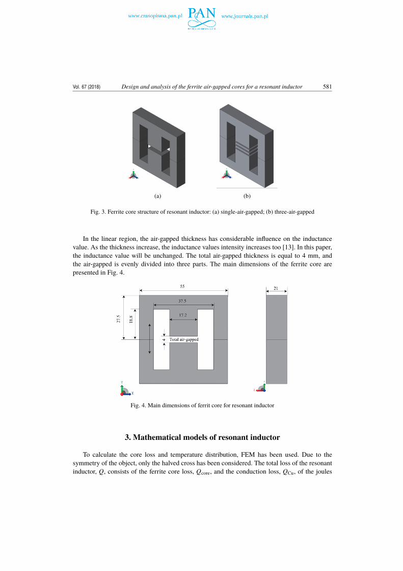
Fig. 3. Ferrite core structure of resonant inductor: (a) single-air-gapped; (b) three-air-gapped
In the linear region, the air-gapped thickness has considerable influence on the inductancevalue. As the thickness increase, the inductance values intensity increases too [13]. In this paper,the inductance value will be unchanged. The total air-gapped thickness is equal to 4 mm, andthe air-gapped is evenly divided into three parts. The main dimensions of the ferrite core arepresented in Fig. 4.
Fig. 4. Main dimensions of ferrit core for resonant inductor
3. Mathematical models of resonant inductor
To calculate the core loss and temperature distribution, FEM has been used. Due to thesymmetry of the object, only the halved cross has been considered. The total loss of the resonantinductor, Q, consists of the ferrite core loss, Qcore, and the conduction loss, QCu, of the joules

582 J. Zheng, C. Wang, D. Xia Arch. Elect. Eng.
loss in the coils. Moreover, Qcore can be divided into the material loss, Qmat, derived from themain flux density flowing in the rolling direction and transverse direction, and the eddy currentloss, Qeddy, due to leakage magnetic flux flowing vertical to laminating direction [14]. Therefore,Q can be defined as:
Q = Qcore +QCu = Qmat +Qeddy +QCu . (1)
3.1. Electromagnetics fields calculationThe material loss Qmat is obtained from the following Steinmetz’s equation made by datasheet
(EE55/28/21):
Qmat =
n∑i=1
(KhB2
(i) f + KeB2(i) f 2
)V (i) , (2)
where Kh and Ke are the coefficients calculated from the datasheet, B is the magnetic flux density,f is the frequency, V is the volume, and n is the number of elements, it means the element number.The material loss is caused by main flux density, B, from the rolling direction and the transversedirection.
The eddy current loss by the leakage magnetic flux is calculated with the Elektra-SS modulusof the Opera-3D package [15]. In the paper, the A-V -A method is adopted in a 3D eddy currentanalysis model for FEM. In the region where the eddy currents arise, the equation for the totalvector potential A and an electric scalar potential V has to be solved as the following:
∇ × 1µ∇ × A − ∇ 1
µ∇ × A + σ
∂A∂t+ σ∇V = 0 , (3)
where σ is the electrical conductivity, and µ is the magnetic permeability of the material.According to Equation (3), the eddy current loss Qeddy is achieved as the following:
Qeddy =1σ|J |2 = 1
σ
�����∇ × 1µ∇ × A
�����2, (4)
where J is the current density.The joules loss in the coils is taken into account as the following:
QCu =
k∑j=1
I2( j) R( j) , (5)
where I( j) is the j-th coil current, R( j) is the j-th coil resistance. R( j) can be written as follows:
R( j) = ρl( j)
S( j)=
ρn( j) (MLT)AW Kuα( j)/n( j)
=ρn2
( j) (MLT)
AW Kuα( j), (6)
where ρ is the coil density, l( j) is the j−th coil length, S( j) is the j−th coil area, n( j) is the turnnumber, MLT is mean the length per turn, AW is the core windows area, α( j) is the fraction of thej−th coil windows area, and Ku is the winding fill factor.

Vol. 67 (2018) Design and analysis of the ferrite air-gapped cores for a resonant inductor 583
According to Equation (5) and (6), the joules loss in the coils can be defined as follows:
QCu =ρ(MLT)AW Ku
k∑j=1
I2( j)n
2( j)
α( j). (7)
The joules loss is optimal provided as follows [15]:
QCu =ρ(MLT)AW Ku
k∑j=1
I( j)n( j)
α( j). (8)
3.2. Thermal fields calcaulationThe heating phenomenon depends on thermal conductivity λ, thermal capacitance c, mass
density ρ, feed thermal power density Q, and the thermal power exchange between the objectand surrounding. The material propriety parameters are shown in Table 1. For calculation thetemperature T , a heat conduction equation is given in the thermal field as the following [16]:
∇ · (λ∇T ) +Q = ρc∂T∂t
. (9)
Table 1. Material properties used in thermal model
Property Ferrite Copper Bobbin AirThermal conductivity λ [W/(m·K)] 5 401 0.22 0.031
Thermal capacitance c [J/(kg·K)] 750 386 1000 1007
Mass density ρ [kg/m3] 4850 8930 1600 1.205
In the temperature field analysis, boundary conditions should be imposed. Outer surface isa vertical square surface and can be assumed as a vertical plate. Two types of heat transfer canoccur in the outer surface, including radiation and natural convection. On the calculation regionboundaries, T0 = 25◦C has been forced as Dirichlet’s condition. The heat transfer boundarycondition on the surface of the inductor is given as the following:
λ(n · ∇T ) + h(T − T0) = 0, (10)
where n is the normal vector outside of the border, h is the heat transfer coefficient, and T0 is theambient temperature.
Thermal radiation phenomenon is not included in the Tempo solver. Thus, we have modifiedthe boundary condition coefficient taking into account the radiation coefficient in the heatingprocess, according to the following equation [17].
heq = h + 4σBε ((T + T0)/2)3 , (11)
where σB is the Stefan-Boltzmann constant and ε = 0.9 is the emittance value.In order to calculate electromagnetic and thermal fields, a suggested flow chart is shown in
Fig. 5. Firstly, some electromagnetic data are input such as material properties, ambient tempera-ture, simulation time and step size. According to eddy current region control, the electromagnetic

584 J. Zheng, C. Wang, D. Xia Arch. Elect. Eng.
calculation and analysis are carried on. Secondly, the eddy current loss and the joules loss areused as the heat generating source load of the thermal field. The calculation and analysis of thethermal field are carried out for the inductor surface and internal temperature. Then, determinewhether the set time is up to the simulation end time. If not met, update parameters of the materialproperties according to the calculated temperature. While you increase the simulation time step,calculate the electromagnetic field again, and repeat the process until the end time. When thesimulation is done, the results are saved and transferred to the treatment store so as to be read,viewed and ready for other operation.
Fig. 5. Flow chart to coupling fieldcalculation
4. Results Analysis and Air-gapped Optimization Discussion
In the paper, the calculations and measurements have been carried out for both a single-air-gapped and three-air-gapped ferrite core of the considered inductor. In the case of both analyzedmodels, the maximal values of the magnetic flux density inside the core is equal to Bm = 0.3 T.The supply frequency of the sinusoidal current wave is f = 10 kHz, and the current RMS is equalto I = 13 A. The electromagnetic and thermal fields are calculated and analyzed for the resonantinductor using FEM.
4.1. Electromagnetic fields analysisFig. 6 shows the distribution of magnetic flux density B in the resonant inductor core at the
time of maximum coil current.

Vol. 67 (2018) Design and analysis of the ferrite air-gapped cores for a resonant inductor 585
(a) (b)
Fig. 6. Magnetic flux density of resonant inductor ferrite core: (a) single-air-gapped core;(b) three-air-gapped core
In the single-air-gapped core model shown in Fig. 6(a), it can be observed that there arelarge magnetic flux densities compared with the three-air-gapped model shown in Fig. 6(b). Theleakage magnetic flux cannot enter into the ferrite core, because of having permeability on theY-direction. The magnetic flux concentrates on the surface of the core. On the other hand, themagnetic flux densities near the gap are distributed uniformly on the three-air-gapped modelbecause the leakage magnetic flux densities are small. Eddy current is induced in the ferrite coredue to leakage magnetic flux. Therefore, the proposed three-air-gapped core structure can reduceeddy current loss.
Fig. 7 shows the distribution of ferrite core loss Q. From the simulation, it can be obtained thatthe maximum loss density is Q = 3425600 W/m3 in a single-air-gapped core as shown in Fig. 7(a).By contrast, the maximum loss density is Q = 2558800 W/m3 in three-air-gapped core as shown
(a) (b)
Fig. 7. Ferrite core loss of resonant inductor ferrite core: (a) single-air-gapped core;(b) three-air-gapped core

586 J. Zheng, C. Wang, D. Xia Arch. Elect. Eng.
in Fig. 7(b). As a conclusion, in this section, it is revealed that the proposed three-air-gappedstructure can reduce ferrite core loss.
4.2. Thermal fields analysis
The obtained loss distribution has been assumed for the thermal model. In this simulation,it is assumed that the heat transfer between the coil and core of the inductor has been naturallydone. The film coefficient is considered equal to 10 W/m2◦C.
Fig. 8 shows the static thermal field distribution in the resonant inductor, and Fig. 9 shows thestatic thermal field distribution in the ferrite core of the resonant inductor. From the simulation, itcan be seen that the higher temperature is distributed in the ferrite core. The maximum temperaturevalue of the single-air-gapped core inductor reaches 65◦C, whereas for the three-air-gapped coreinductor, the maximum temperature value is equal to 53◦C. By contrast, the proposed three-air-
(a) (b)
Fig. 8. Temperature distribution of resonent inductor: (a) single-air-gapped core; (b) three-air-gapped core
(a) (b)
Fig. 9. Temperature distribution of resonent inductor ferrite core: (a) single-air-gapped core;(b) three-air-gapped core

Vol. 67 (2018) Design and analysis of the ferrite air-gapped cores for a resonant inductor 587
gapped core can decrease temperature by more than 10 degree. Therefore the three-air-gappedstructure is adopted to decrease temperature rise.
4.3. Air-gap position discussion
In this paper, the air-gap position is discussed. Because the total thickness of air-gap isunchanged and its value is 4mm, the selection of the air-gap position depends on the thickness offerrite core block S as shown in Fig. 10.
Fig. 10. Cross-section of three-air-gappedferrite core
In order to find the air-gap position that leads to the lowest temperature rise, many simulationand calculation have been carried out. The maximum temperature curve for the length of amagnetic core block is presented as shown in Fig. 11.
Fig. 11. The maximum temperature curve for the length of magnetic core block
From Fig. 11, it can be seen that when the length value of the magnetic core block is 5 mm,the maximum temperature of the ferrite core is 52.5◦C, that is the lowest temperature rise. Asa conclusion, it is revealed that the optimal positions of three air-gaps are respectively (−7.00,−5.67), (−0.67, 0.67), (5.67, 7.00) on the Y-direction.

588 J. Zheng, C. Wang, D. Xia Arch. Elect. Eng.
5. Conclusion
In this paper, a modeling procedure and the design criterion for the simulation in a 3D ofa ferrite air-gapped core for a resonant inductor have been proposed. The electromagnetic fieldand thermal field of the resonant inductor have been calculated and analyzed. The simulationreveals that the three-air-gapped core can reduce eddy current loss and can decrease temperaturerise compared with a single-air-gapped core. Furthermore, the maximum temperature curve forthe length of a magnetic core block is presented, and it reveals the optimal positions of its threeair-gaps.
References
[1] Wu W., Huang M., Blaabjerg F., Efficiency comparison between the LLCLand LCL-filters basedsingle-phase grid-tied inverters, Archives of Electrical Engineering, vol. 63, no. 1, pp. 63–79 (2014).
[2] Kundu U., Yenduri K., Sensarma P., Accurate ZVS Analysis for Magnetic Design and EfficiencyImprovement of Full-Bridge LLC Resonant Converter, IEEE Transactions on Power Electronics, vol. 32,no. 3, pp. 1703–1706 (2017).
[3] Zong S., Luo H., Li W., Theoretical Evaluation of Stability Improvement Brought by Resonant CurrentLoop for Paralleled LLC Converters, IEEE Transactions on Industrial Electronics, vol. 62, no. 7,pp. 4170–4180 (2015).
[4] Seeman M.D., GaN Devices in Resonant LLC Converters: System-level considerations, IEEE PowerElectronics Magazine, vol. 2, no. 1, pp. 36–41 (2015).
[5] Macrelli E., Romani A. et al., Modeling, Design, and Fabrication of High-Inductance Bond WireMicrotransformers With Toroidal Ferrite Core, IEEE Transactions on Power Electronics, vol. 30,no. 10, pp. 5724–5737 (2015).
[6] Salas R.A., Pleite J., Equivalent Electrical Model of a Ferrite Core Inductor Excited by a Square Wave-form Including Saturation and Power Losses for Circuit Simulation, IEEE Transactions on magnetics,vol. 49, no. 7, pp. 4257–4260 (2013).
[7] Ahour J.N., Seyedtabah A., Gharehpetian G.B., On the accuracy of detailed model inductance matrixestimation for air core winding, Archives of Electrical Engineering, vol. 66, no. 4, pp. 787–799 (2017).
[8] Hilal A., Raulet M.A., Martin C., Sixdenier F., Power Loss Prediction and Precise Modeling ofMagnetic Powder Components in DC–DC Power Converter Application, IEEE Transactions on PowerElectronics, vol. 30, no. 4, pp. 2232–2238 (2015).
[9] Gao Y. et al., Loss reduction of reactor with grain-oriented silicon steel plates, IEEE Transaction onMagnetics, vol. 49, no. 5, pp. 1973–1976 (2013).
[10] Salas R.A., Pleite J., Simulation of the Saturation and Air-Gap Effects in a POT Ferrite Core With a2-D Finite Element Model, IEEE Transactions on Magnetics, vol. 47, no. 10, pp. 4135–4138 (2011).
[11] Kurita N., Onda K., Nakanoue K., Inagaki K., Loss estimation method for three-phase AC reactors oftwo types of structures using amorphous wound cores in 400-kVA UPS, IEEE Transactions on PowerElectronics, vol. 29, no. 7, pp. 3657–3688 (2014).
[12] Tomczuk B., Babczyk K., Calculation of the self- and mutual inductances and 3-D magnetic fieldsof chokes with air gaps in core, Electrical Engineering (Archiv fur Elektrotechnik), Springer-Verlag,Berlin, vol. 83, pp. 41–46 (2001).
[13] Macrelli E. et al., Modeling, Design, and Fabrication of High-Inductance Bond Wire Microtransform-ers With Toroidal Ferrite Core, IEEE Transactions on Power Electronics, vol. 30, no. 10, pp. 5724–5737(2015).

Vol. 67 (2018) Design and analysis of the ferrite air-gapped cores for a resonant inductor 589
[14] Tsili M.A., Amoiralis E.I., Kladas A.G., Souflaris A.T., Power transformer thermal analysis by usingan advanced coupled 3D heat transfer and fluid flow FEM model, International Journal of ThermalSciences, vol. 53, pp. 188–201 (2012).
[15] Zhiguang C., Takahashi N., Forghani B. et al., Electromagnetic and Thermal Field Modeling andApplication in Electrical Engineering, Science China Press (2009).
[16] Hayt W.H., Buck J.A., Engineering Electromagnetics, 7th Edition, the McGraw-Hill Companies, Inc.(2006).
[17] Tomczuk B.Z. et al., Electromagnetic and temperature 3-D fields for the modular transformers heatingunder high-frequency operation, IEEE Trans. Magn., vol. 50, no. 2 (2014).


![Ferrite - Coretech2004].pdf · Ferrite For Switching Power Supplies Circuit Example SINGLE FORWARD CONVERTER Notes: • LP and EPC cores are ideal for use in thin transformers. •](https://static.fdocuments.net/doc/165x107/5e13d9249413ab0b4f1ca18c/ferrite-2004pdf-ferrite-for-switching-power-supplies-circuit-example-single.jpg)
