Design and Analysis Of Multistory Building With Seismic ...
20
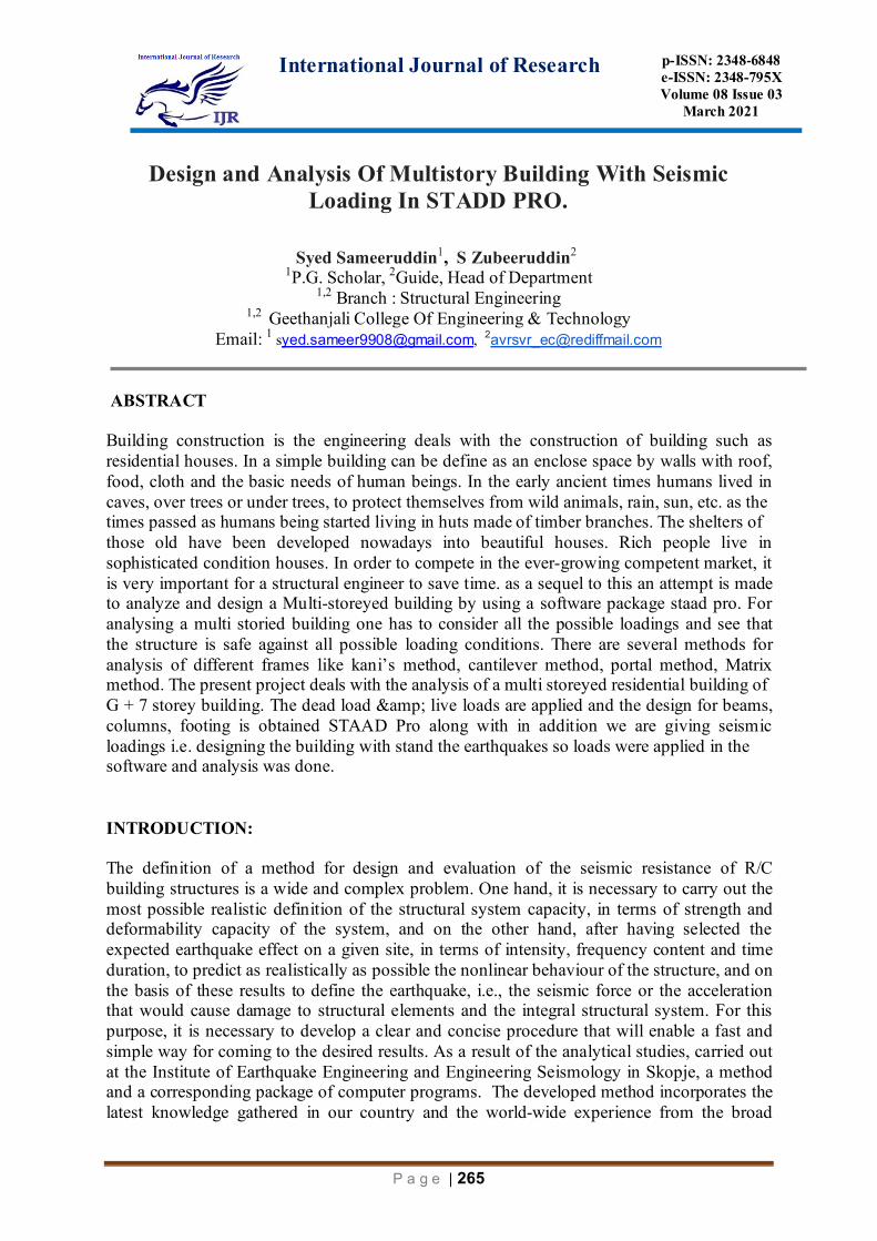
International Journal of Research p- ISSN: 2348- 6848 e-ISSN: 2348-795X Volume 08 Issue 03 March 2021 Page | 265 Design and Analysis Of Multistory Building With Seismic Loading In STADD PRO. Syed Sameeruddin 1 , S Zubeeruddin 2 1 P.G. Scholar, 2 Guide, Head of Department 1,2 Branch : Structural Engineering 1,2 Geethanjali College Of Engineering & Technology Email: 1 s[email protected] , 2 [email protected] ABSTRACT Building construction is the engineering deals with the construction of building such as residential houses. In a simple building can be define as an enclose space by walls with roof, food, cloth and the basic needs of human beings. In the early ancient times humans lived in caves, over trees or under trees, to protect themselves from wild animals, rain, sun, etc. as the times passed as humans being started living in huts made of timber branches. The shelters of those old have been developed nowadays into beautiful houses. Rich people live in sophisticated condition houses. In order to compete in the ever-growing competent market, it is very important for a structural engineer to save time. as a sequel to this an attempt is made to analyze and design a Multi-storeyed building by using a software package staad pro. For analysing a multi storied building one has to consider all the possible loadings and see that the structure is safe against all possible loading conditions. There are several methods for analysis of different frames like kani’s method, cantilever method, portal method, Matrix method. The present project deals with the analysis of a multi storeyed residential building of G + 7 storey building. The dead load & live loads are applied and the design for beams, columns, footing is obtained STAAD Pro along with in addition we are giving seismic loadings i.e. designing the building with stand the earthquakes so loads were applied in the software and analysis was done. INTRODUCTION: The definition of a method for design and evaluation of the seismic resistance of R/C building structures is a wide and complex problem. One hand, it is necessary to carry out the most possible realistic definition of the structural system capacity, in terms of strength and deformability capacity of the system, and on the other hand, after having selected the expected earthquake effect on a given site, in terms of intensity, frequency content and time duration, to predict as realistically as possible the nonlinear behaviour of the structure, and on the basis of these results to define the earthquake, i.e., the seismic force or the acceleration that would cause damage to structural elements and the integral structural system. For this purpose, it is necessary to develop a clear and concise procedure that will enable a fast and simple way for coming to the desired results. As a result of the analytical studies, carried out at the Institute of Earthquake Engineering and Engineering Seismology in Skopje, a method and a corresponding package of computer programs. The developed method incorporates the latest knowledge gathered in our country and the world-wide experience from the broad
Transcript of Design and Analysis Of Multistory Building With Seismic ...
International Journal of Research
p-ISSN: 2348-6848 e-ISSN: 2348-795X Volume 08 Issue 03
March 2021
P a g e | 265
Design and Analysis Of Multistory Building With Seismic Loading In STADD PRO.
Syed Sameeruddin1, S Zubeeruddin2 1P.G. Scholar, 2Guide, Head of Department
1,2 Branch : Structural Engineering 1,2 Geethanjali College Of Engineering & Technology
Email: 1 [email protected], [email protected] ABSTRACT Building construction is the engineering deals with the construction of building such as residential houses. In a simple building can be define as an enclose space by walls with roof, food, cloth and the basic needs of human beings. In the early ancient times humans lived in caves, over trees or under trees, to protect themselves from wild animals, rain, sun, etc. as the times passed as humans being started living in huts made of timber branches. The shelters of those old have been developed nowadays into beautiful houses. Rich people live in sophisticated condition houses. In order to compete in the ever-growing competent market, it is very important for a structural engineer to save time. as a sequel to this an attempt is made to analyze and design a Multi-storeyed building by using a software package staad pro. For analysing a multi storied building one has to consider all the possible loadings and see that the structure is safe against all possible loading conditions. There are several methods for analysis of different frames like kani’s method, cantilever method, portal method, Matrix method. The present project deals with the analysis of a multi storeyed residential building of G + 7 storey building. The dead load & live loads are applied and the design for beams, columns, footing is obtained STAAD Pro along with in addition we are giving seismic loadings i.e. designing the building with stand the earthquakes so loads were applied in the software and analysis was done. INTRODUCTION: The definition of a method for design and evaluation of the seismic resistance of R/C building structures is a wide and complex problem. One hand, it is necessary to carry out the most possible realistic definition of the structural system capacity, in terms of strength and deformability capacity of the system, and on the other hand, after having selected the expected earthquake effect on a given site, in terms of intensity, frequency content and time duration, to predict as realistically as possible the nonlinear behaviour of the structure, and on the basis of these results to define the earthquake, i.e., the seismic force or the acceleration that would cause damage to structural elements and the integral structural system. For this purpose, it is necessary to develop a clear and concise procedure that will enable a fast and simple way for coming to the desired results. As a result of the analytical studies, carried out at the Institute of Earthquake Engineering and Engineering Seismology in Skopje, a method and a corresponding package of computer programs. The developed method incorporates the latest knowledge gathered in our country and the world-wide experience from the broad

International Journal of Research
p-ISSN: 2348-6848 e-ISSN: 2348-795X Volume 08 Issue 03
March 2021
P a g e | 266
fields of the earthquake engineering: determination of strength and deformability characteristics of the building, on one hand, and definition of the nonlinear behavior of the structure for a given earthquake effect, on the other hand. The idea of using displacement in the design process is not a new one. In 1974, Golan and Sized discussed that the design of the structure could be modeled as a single degree of freedom system. That work formed the basis of the so-called "substitute structure approach". The substitute structure is an elastic structure that has the same peak force and peak displacement characteristics as the inelastic structure. This modeling is required because Displacement -based design (DBD) procedure used an elastic response spectra for the design of a structure that is expected to have inelastic deformation in the design level earthquake. DBD procedure is alternative seismic design procedure that designs the structure for the requirements based on the displacements rather than forces. The only initial design input parameter is the maximum allowable displacement. Design forces, stiffness and reinforcement details all become dependent on the target displacement. Presented in the paper are the main characteristics of these two methodologies for seismic design of R/C structures. Design of G+7 building: Using M25 and Fe 415 grade of concrete and steel for beams, slabs, footings, columns. Therefore:- fck = Characteristic strength for M25-25N/mm2 fy= Characteristic strength of steel-415N/mm2 Earthquake shaking is random and time variant. But, most design codes represent the earthquake-induced inertia forces as the net effect of such random shaking in the form of design equivalent static lateral force. This force is called as the Seismic Design Base Shear VB and remains the primary quantity involved in the force-based earthquake-resistant design of buildings. This force depends on the seismic hazard at the site of the building represented by the Seismic Zone Factor Z. Codes reflect this by the introduction of a Structural Flexibility Factor Sa/g. This philosophy is introduced with the help of Response Reduction Factor R, which is larger for ductile buildings and smaller for brittle ones Thus, the design of earthquake effects is not termed as earth quakeproof design. Instead, the earthquake demand is estimated only based on concepts of the probability of evidence, and the design of earthquake effects is termed as earthquake-resistant design against the probable value of the demand. The Design Base Shear VB is taken as per the Indian Seismic Code IS 1893 (Part 1) – 2007. Modern architecture: The Bauhaus Dessau architecture department from 1925 by Walter Gropius.The dissatisfaction with such a general situation at the turn of the 20thcentury gave rise to many new lines of thought that served as precursors to modern architecture. Notable among these is detachers’ deskbound, formed in 1907 to produce better quality machine made objects. The rise of the profession of industrial design is usually placed here. Following this lead, the Bauhaus school, founded in Weimar, Germany in 1919, redefined the architectural bounds prior set throughout history viewing the creation of a building as the ultimate synthesis—the apex—of art, craft and technology. When modern architecture was first practiced, it was an avant-garde moment with moral, philosophical, and aesthetic underpinning. Immediately

International Journal of Research
p-ISSN: 2348-6848 e-ISSN: 2348-795X Volume 08 Issue 03
March 2021
P a g e | 267
after world war I, pioneering modernist architects sought to develop a completely new style appropriate for a new post-war social and economic order, focused on meeting the needs of the middle and working classes. They rejected the architectural practice of the academic refinement of historical styles which served the rapidly declining aristocratic order. Statement of project:
Plan of Residential Building (G+7)
Specifications listed below: RCC Building Size of beam = 0.7X0.45 Size of columns= 0.45X0.45 Slab thickness = 150 mm Height of each floors are 3m Material Concrete Support Fixed Load Calculation: - Dead load (IS:875 Part 1) Live load (IS:875 Part 2) Seismic load (IS 1893-2005) Dead Load Calculation: - Self -weight of slab = 0.15X25=3.75 Exterior wall=0.35X2.45X20 = 17.15+2 = 19.15 Partition wall = 0.2X2.45X20=9.8+2=11.8 Parapet wall = 0.2X1.5X20=6+2 = 8 Plaster for two faces = 0.02X2.45X1X18X2=2 Code used IS-1893-2002 for seismic load (Part 1 to 4) Seismic load Method for analysis
1. Equivalent static Method 2. Lumped mass model Method

International Journal of Research
p-ISSN: 2348-6848 e-ISSN: 2348-795X Volume 08 Issue 03
March 2021
P a g e | 268
3. Response Spectrum Method In this example we considered equivalent static method. code used IS 1893-2005 VB=AhXW Where, VB = Design Seismic base shear Ah = Average response acceleration co-efficient W=Sesimic weight of the building(W=D.L+50%L.L) Ah=Z/2p*T%R*Sa%g Where, I=Importance factor (Table 6) Z=importance factor (Table 2) R=Response reduction factor (Table 7) Sa/g=design acceleration spectrum Ta=0.09h/sqrD Ta=0.68sec, D=0.09*24/sqr10 Where, h=height of the building(h=24m) D is base dimension of the building(D=10m) The design base shear(VB)shall be disturbed along the height of the building as per the following expression: In the limit state design of reinforced and prestressed concrete structure, the following load combinations shall be accounted for: 1)1.5(DL+LL) 2)1.2(DL+LL+EL) 3)1.5(DL+EL) 4)0.9(DL+1.5EL)
Method of analysis of statistically indeterminate portal frames: 1. Method of flexibility coefficients. 2. Slope displacements methods (iterative methods) 3. Moment distribution method 4. Kane’s method 5. Cantilever method 6. Portal method 7. Matrix method 8. STAAD Pro Design 2.1 Assumptions Regarding Design: Slab is assumed to be continuous over interior support and partially fixed on edgesdue to monolithic construction and due to construction of walls over it. ii) Beams are assumed to be continuous over interior support and they frame in to the column at ends. Specifications listed below: RCC Building
International Journal of Research
p-ISSN: 2348-6848 e-ISSN: 2348-795X Volume 08 Issue 03
March 2021
P a g e | 269
Size of beam = 0.7X0.45 Size of columns= 0.45X0.45 Slab thickness = 150 mm Height of each floors are 3m. Material: Concrete. Support: Fixed. 2.2 Assumptions on design: -
M25grade is used in designing unless specified. Tor steel Fe 415 is used for the main reinforcement. Tor steel Fe 415 and steel is used for the distribution reinforcement. Mild steel Fe 230 is used for shear reinforcement
2.3 Assumptions Regarding Design: Slab is assumed to be continuous over interior support and partially fixed on edges, due to monolithic construction and due to construction of walls over it. Beams are assumed to be continuous over interior support and they frame in to the column atends. 2.4 Assumptions on design: M20grade is used in designing unless specified. Tor steel Fe 415 is used for the main reinforcement. Tor steel Fe 415 and steel is used for the distribution reinforcement. Mild steel Fe 230 is used for shear reinforcement
2.5 Assumptions Regarding Design: i. Slab is assumed to be continuous over interior support and partially fixed
on edges,due to monolithic construction and due to construction of walls over it. ii. Beams are assumed to be continuous over interior support and they frame in to the
column atends.

International Journal of Research
p-ISSN: 2348-6848 e-ISSN: 2348-795X Volume 08 Issue 03
March 2021
P a g e | 270
Fig :We have defined and assigned fixed supports.
3.LOADS: To apply loads in the model we have to know some basics of loading: Loads that we use............ Dead loads Live loads Earthquake loads Temperature loads Snow loads etc...

International Journal of Research
p-ISSN: 2348-6848 e-ISSN: 2348-795X Volume 08 Issue 03
March 2021
P a g e | 271
3.1DEAD LOADS: Deal load refers to loads that relatively don’t change over time, such as the weight of
All permanent components of a building including walls, Beam, columns, flooring material etc.)
Fixed permanent equipment and fitting that are an integral part of the structure.(like plumbing, HVAC, etc.)
The dead loads are calculated from the member sizes and estimated material densities.
Unit weight of building materials can be estimated in accordance with IS: 875 (Part 1).
In this load section we have to define all the dead loads which includes following...... Self-weight of all members Weight of walls and other concentrated loads (member loads or point loads) Floor loads Weight of slabs Loads of furniture's, utilities etc. defined in codes (IS875-pat1). Load Calculation: - Dead load (IS: 875 Part 1) Live load (IS: 875 Part 2) Seismic load (IS 1893-2005) Dead Load Calculation:- Self -weight of slab = 0.15X25=3.75 Exterior wall=0.35X2.45X20 = 17.15+2 = 19.15 Partition wall = 0.2X2.45X20=9.8+2=11.8 Parapet wall = 0.2X1.5X20=6+2 = 8 Plaster for two face = 0.02X2.45X1X18X2=2 Code used IS-1893-2002 for seismic load (Part 1 to 4) Seismic load Method for analysis Equivalent static Method Lumped mass model Method Response Spectrum Method In this example we considered equivalent static method. code used IS 1893-2005 VB=AhXW Where, VB = Design Seismic base shear Ah = Average response acceleration co-efficient W=Seismic weight of the building (W=D.L+50%L.L) Ah=Z/2p*T%R*Sa %g Where, I=Importance factor (Table 6) Z=importance factor (Table 2) R=Response reduction factor (Table 7) Sa/g=design acceleration spectrum

International Journal of Research
p-ISSN: 2348-6848 e-ISSN: 2348-795X Volume 08 Issue 03
March 2021
P a g e | 272
Ta=0.09h/sq r D Ta=0.68sec,D=0.09*24/sqr10 Where, h=height of the building (h=24m) D is base dimension of the building (D=10m) The design base shear (VB) shall be disturbed along the height of the building as per the following expression: In the limit state design of reinforced and prestressed concrete structure, the following load combinations shall be accounted for: 1)1.5(DL+IL) 2)1.2(DL+IL+EL) 3)1.5(DL+EL) 4)0.9DL+1.5EL For foundation D.L+L.L D.L+0.5L.L+-EQX,Z D.L+-EQX,Z All permanent constructions of the structure form the dead loads. The dead load comprises of the weights of walls, partitions floor finishes, false ceilings, false floors and the other permanent constructions in the buildings. The dead load loads may be calculated from the dimensions of various members and their unit weights. the unit weights of plain concrete and reinforced concrete made with sand and gravel or crushed natural stone aggregate may be taken as 24 kn/m” and 25 kn/m” respectively. MAIN WALL LOAD (From Above Plinth Area to Below The Roof) Should Be The Cross Sectional Area Of The Wall Multiplied By Unit Weight Of The Brick. (UnitWeight Of Brick Is Taken As 19.2 KN/m3). According To The Is-Code PLINTH LOAD Should Be Half Of The Main Wall Load. Internal Plinth Load Should Be Half Of The Plinth Load. Parapet Load Should Be the Cross Sectional Is Multiplied By Unit Weight.
International Journal of Research
p-ISSN: 2348-6848 e-ISSN: 2348-795X Volume 08 Issue 03
March 2021
P a g e | 273
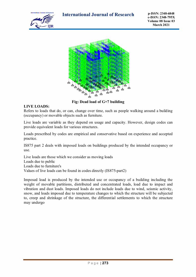
Fig: Dead load of G+7 building
LIVE LOADS: Refers to loads that do, or can, change over time, such as people walking around a building (occupancy) or movable objects such as furniture.
Live loads are variable as they depend on usage and capacity. However, design codes can provide equivalent loads for various structures.
Loads prescribed by codes are empirical and conservative based on experience and accepted practice.
IS875 part 2 deals with imposed loads on buildings produced by the intended occupancy or use.
Live loads are those which we consider as moving loads Loads due to public Loads due to furniture's Values of live loads can be found in codes directly (IS875-part2) Imposed load is produced by the intended use or occupancy of a building including the weight of movable partitions, distributed and concentrated loads, load due to impact and vibration and dust loads. Imposed loads do not include loads due to wind, seismic activity, snow, and loads imposed due to temperature changes to which the structure will be subjected to, creep and shrinkage of the structure, the differential settlements to which the structure may undergo

International Journal of Research
p-ISSN: 2348-6848 e-ISSN: 2348-795X Volume 08 Issue 03
March 2021
P a g e | 274
Fig: Live load assigned to the structure
SEISMIC LOAD: How do earthquakes affect buildings: Seismic loading is one of the basic concepts of earthquake engineering which means application of an earthquake-generated agitation to a structure. It happens at contact surfaces of a structure either with the ground, or with adjacent structures,[3] or with gravity waves from tsunami. Seismic loading depends primarily on:
Anticipated earthquake's parameters at the site - known as seismic hazard Geotechnical parameters of the site Structure's parameters Characteristics of the anticipated gravity waves from tsunami (if applicable). Sometimes, seismic load exceeds ability of a structure to resist it without being broken, partially or completely Due to their mutual interaction; seismic loading and seismic performance of a structure are intimately related. SEISMIC LOAD CALCULATION: Design Lateral Force: The design lateral force shall first be computed for the building as a whole. This design lateral force shall then be distributed to the various floor levels. The overall design seismic

International Journal of Research
p-ISSN: 2348-6848 e-ISSN: 2348-795X Volume 08 Issue 03
March 2021
P a g e | 275
force thus obtained at each floor level shall then be distributed to individual lateral load resisting elements depending on the floor diaphragm action.
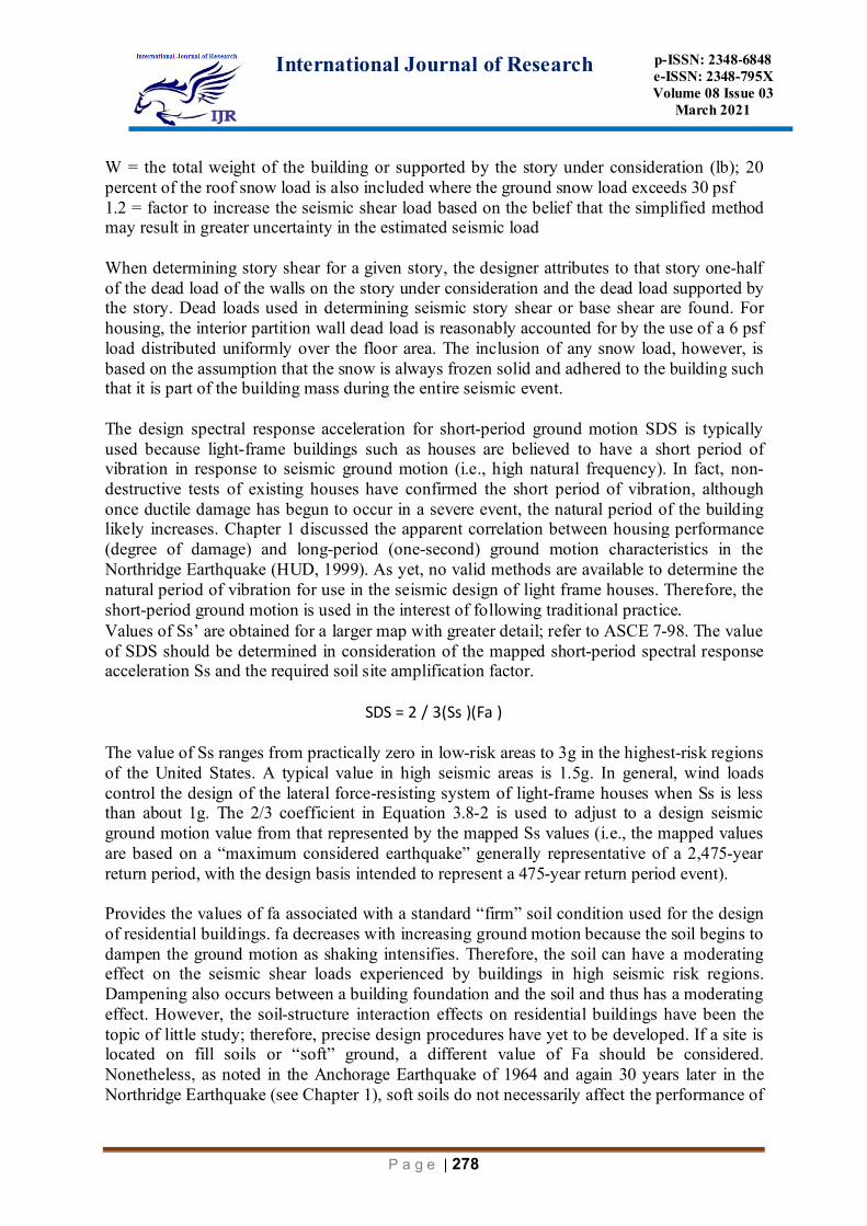
FIGURE: Seismic Map of Design Short-Period Spectral Response Acceleration (g) (2 present chance of exceedance in 50 years or 2,475-year return period). Seismic load and design earthquake motion: For ordinary buildings, an equivalent static load is calculated using a response spectrum method and is to be used for static stress analysis (this series of procedure may be referred to as the equivalent static analysis). The response spectrum method is basically applicable only for elastic structures, but can be used to approximately estimate elasto-plastic structures with uniform plasticity within the structures. Most often, the horizontal components of seismic loads are significant for ordinary buildings; the vertical components may be neglected. The ordinary conditions mentioned above. In case that there is non-uniform plasticity within a building, or if the vertical vibration cannot be ignored, or for buildings which tend to behave as in the following items from a) to h), dynamic analyses (time-history response analyses) with design ground motions mentioned in Sec.7.3 should be implemented in order to verify the seismic safety. a) A building with abrupt change in horizontal stiffness and strength in height and possible
damage concentration in a particular story b) A building with plane irregularity in mass and stiffness and significant torsional response c) A building which is composed of frames with large-spanned beams and/or long
cantilevers and the vertical vibration cannot be ignored d) A non-multi-story and special shape building like shells and spatial structures e) A tall building and a large sized building with great importance f) A building which contains telecommunication devices and valuable contents, and whose
structural dynamic response must be estimated g) A building which contains dangerous materials, and whose failure may greatly affect the
surroundings h) A building with special devices such as base-isolation systems Note that static analysis in
is also preferably carried out in order to grasp the required safety level even in the case that dynamic analysis is implemented. Although only a seismic load for static analyses described in is given in the previous version of the recommendations, the current

International Journal of Research
p-ISSN: 2348-6848 e-ISSN: 2348-795X Volume 08 Issue 03
March 2021
P a g e | 276
recommendations cover the design ground motions for dynamic analyses described in the main text. It is described in that the seismic load used for the equivalent static analysis shall be calculated with the following two procedures. One procedure is a response spectrum method in which an eigenvalue analysis of a building model is first implemented and then superposition of each modal response based on the response spectrum is made to determine the seismic load. Another procedure is the simplified method without performing the eigenvalue analysis. In the above two procedures, the seismic load is based on the story-shear force computed from the acceleration response spectra and based on two modification factors: a reduction factor due to plastic deformation capacity and an amplification factor due to building irregularity. The response spectrum is defined on the outcropped engineering bedrock and is based on the standard probabilistic seismic hazard map with respect to peak ground acceleration (PGA) taking account of spectral property, amplification of wave motion through shallow ground layers above the bedrock, and effect of soil-structure interaction. Compares the seismic load of this recommendation and that of the previous version. Once the response spectrum is evaluated, the seismic load can be calculated as the design story shear force. When the vibrational modes higher than the first mode are significant, it is desirable to perform an eigenvalue analysis.
Fig: earth quake of x-direction
Idealization of building and location of input ground motion: An actual building is very complex, but the building is often idealized into an adequate mathematical model to evaluate the seismic load. A lumped mass structural model is often used since most of mass is concentrated on each floor of the building. The building located on a firm ground can be modeled as a fixed base model as illustrated. The mass concentration on the floor level is assumed to move horizontally and independently with disregard to the motion in another orthogonal direction. If the ground supporting a building is not stiff, the so called “SR model” (Sway-Rocking model), which can represent sway and rocking motions of the foundation, should be used to take account of the soil-structure interaction effect. May sometimes be used to take account of motions of the ground and pile foundations. Note that treatment of SSI effect is discussed. If the mass and stiffness of a building is not evenly distributed, two orthogonal horizontal motions are not independent of each other and rotational (torsional) motion is excited. Therefore, three degrees of freedom (two horizontal and torsion) should be considered for each story. For such dynamic systems with torsional motion, response spectrum method can also be applied. But the assumption that the maximum of each mode appears independently may not be appropriate, and SRSS (square root of sum of squares) rule to estimate the

International Journal of Research
p-ISSN: 2348-6848 e-ISSN: 2348-795X Volume 08 Issue 03
March 2021
P a g e | 277
maximum response cannot be used. In such cases, CQC (complete quadratic combination) rule is used considering the correlations between eigenmodes of vibration.
Analysis by Space Frames: The space frame is modeled using standard software. The gravity loads are taken from Figure 2, while the earthquake loads are taken. The basic load cases are shown in Table 1, where X and Z are lateral orthogonal directions. Table 1 Basic Load Cases Used for Analysis
EXTP: EQ load in X direction with torsion positive EXTN: EQ load in X direction with torsion negative EZTP: EQ load in Z direction with torsion positive EZTN: EQ load in Z direction with torsion negative
3.3.4 Determination of Earthquake Loads on Houses: The total lateral force at the base of a building is called seismic base shear. The lateral force experienced at a particular story level is called the story shear. The story shear is greatest in the ground story and least in the top story. Seismic base shear and story shear (V) are determined in accordance with the following equation
V =((1.2 SDS)/R) W Where: SDS = the design spectral response acceleration in the short-period range (g) R = the response modification factor (dimensionless)
International Journal of Research
p-ISSN: 2348-6848 e-ISSN: 2348-795X Volume 08 Issue 03
March 2021
P a g e | 278
W = the total weight of the building or supported by the story under consideration (lb); 20 percent of the roof snow load is also included where the ground snow load exceeds 30 psf 1.2 = factor to increase the seismic shear load based on the belief that the simplified method may result in greater uncertainty in the estimated seismic load When determining story shear for a given story, the designer attributes to that story one-half of the dead load of the walls on the story under consideration and the dead load supported by the story. Dead loads used in determining seismic story shear or base shear are found. For housing, the interior partition wall dead load is reasonably accounted for by the use of a 6 psf load distributed uniformly over the floor area. The inclusion of any snow load, however, is based on the assumption that the snow is always frozen solid and adhered to the building such that it is part of the building mass during the entire seismic event. The design spectral response acceleration for short-period ground motion SDS is typically used because light-frame buildings such as houses are believed to have a short period of vibration in response to seismic ground motion (i.e., high natural frequency). In fact, non-destructive tests of existing houses have confirmed the short period of vibration, although once ductile damage has begun to occur in a severe event, the natural period of the building likely increases. Chapter 1 discussed the apparent correlation between housing performance (degree of damage) and long-period (one-second) ground motion characteristics in the Northridge Earthquake (HUD, 1999). As yet, no valid methods are available to determine the natural period of vibration for use in the seismic design of light frame houses. Therefore, the short-period ground motion is used in the interest of following traditional practice. Values of Ss’ are obtained for a larger map with greater detail; refer to ASCE 7-98. The value of SDS should be determined in consideration of the mapped short-period spectral response acceleration Ss and the required soil site amplification factor.
SDS = 2 / 3(Ss )(Fa ) The value of Ss ranges from practically zero in low-risk areas to 3g in the highest-risk regions of the United States. A typical value in high seismic areas is 1.5g. In general, wind loads control the design of the lateral force-resisting system of light-frame houses when Ss is less than about 1g. The 2/3 coefficient in Equation 3.8-2 is used to adjust to a design seismic ground motion value from that represented by the mapped Ss values (i.e., the mapped values are based on a “maximum considered earthquake” generally representative of a 2,475-year return period, with the design basis intended to represent a 475-year return period event). Provides the values of fa associated with a standard “firm” soil condition used for the design of residential buildings. fa decreases with increasing ground motion because the soil begins to dampen the ground motion as shaking intensifies. Therefore, the soil can have a moderating effect on the seismic shear loads experienced by buildings in high seismic risk regions. Dampening also occurs between a building foundation and the soil and thus has a moderating effect. However, the soil-structure interaction effects on residential buildings have been the topic of little study; therefore, precise design procedures have yet to be developed. If a site is located on fill soils or “soft” ground, a different value of Fa should be considered. Nonetheless, as noted in the Anchorage Earthquake of 1964 and again 30 years later in the Northridge Earthquake (see Chapter 1), soft soils do not necessarily affect the performance of
International Journal of Research
p-ISSN: 2348-6848 e-ISSN: 2348-795X Volume 08 Issue 03
March 2021
P a g e | 279
the above-ground house structure as much as they affect the site and foundations (e.g., settlement, fissuring, liquefaction, etc.). Seismic Shear Force Distribution: As described in the previous section, the vertical distribution of seismic forces to separate stories on a light-frame building is assumed to be in accordance with the mass supported by each story. However, design codes vary in the requirements related to vertical distribution of seismic shear. Unfortunately, there is apparently no clear body of evidence to confirm any particular method of vertical seismic force distribution for light-frame buildings. Therefore, in keeping with the simplified method given inthe approach used in this guide reflects what is considered conventional practice. The horizontal distribution of seismic forces to various shear walls on a given story also varies in current practice for light-frame buildings. Several existing approaches to the design of the lateral force-resisting system of light-frame houses address the issue of horizontal force distribution with varying degrees of sophistication. Until methods of vertical and horizontal seismic force distribution are better understood for application to light-frame buildings, the importance of designer judgment cannot be overemphasized. Seismic Design Category C: The design requirements for structures assigned to SDC C are almost identical to those for SDC B but there are a few important differences. First, some structural systems that can be used for SDC B are not permitted for SDC C because it is believed they will not perform adequately under the more intense ground motions associated with SDC C. In addition, SDC C structures with vertical seismic-forceresisting elements (shear walls, braced frames, moment frames, or combinations of these systems) located in plan such that they can experience significant seismic forces as a result of shaking in either of the major orthogonal building axes must be designed considering this behaviour. An example of such a structure is one with columns common to intersecting braced frames or moment frames aligned in different directions. Another example is a structure with vertical elements aligned in two or more directions that are not orthogonal to each other. The NEHRP Recommended Seismic Provisions requires this type of structure to be designed considering that forces can be incident in any direction. The Provisions permits satisfaction of this requirement by considering 100 percent of the specified design forces applied along one primary axis simultaneously with 30 percent of the specified design forces in an orthogonal direction. When this approach is used, at least two load cases must be considered consisting of 100 percent of the specified forces in direction A taken with 30 percent of the specified forces in direction B and 30 percent of the specified forces in direction A taken with 100 percent of the forces in direction B where directions A and B are, respectively, orthogonally oriented to each other. Load Calculation:- Dead load (IS:875 Part 1) Live load (IS:875 Part 2) Seismic load (IS 1893-2005) Dead Load Calculation:- Self -weight of slab = 0.15X25=3.75
International Journal of Research
p-ISSN: 2348-6848 e-ISSN: 2348-795X Volume 08 Issue 03
March 2021
P a g e | 280
Exterior wall=0.35X2.45X20 = 17.15+2 = 19.15 Partition wall = 0.2X2.45X20=9.8+2=11.8 Parapet wall = 0.2X1.5X20=6+2 = 8 Plaster for two face = 0.02X2.45X1X18X2=2 Code used IS-1893-2002 for seismic load (Part 1 to 4) Seismic load Method for analysis Equivalent static Method Lumped mass model Method Response Spectrum Method In this example we considered equivalent static method. code used IS 1893-2005 VB=AhXW Where, VB = Design Seismic base shear Ah = Average response acceleration co-efficient W=Sesimic weight of the building(W=D.L+50%L.L) Ah=Z/2p*T%R*Sa%g Where, I=Importance factor(Table 6) Z=importance factor(Table 2) R=Response reduction factor(Table 7) Sa/g=design acceleration spectrum Ta=0.09h/sqrD Ta=0.68sec,D=0.09*24/sqr10 Where, h=height of the building(h=24m) D is base dimension of the building(D=10m) The design base shear(VB)shall be disturbed along the height of the building as per the following expression: In the limit state design of reinforced and prestressed concrete structure, the following load combinations shall be accounted for: 1)1.5(DL+LL) 2)1.2(DL+LL+EL) 3)1.5(DL+EL) 4)0.9(DL+1.5EL) RESULTS STAAD SPACE START JOB INFORMATION ENGINEER DATE 28-Dec-17 END JOB INFORMATION INPUT WIDTH 79 UNIT METER KN JOINT COORDINATES

International Journal of Research
p-ISSN: 2348-6848 e-ISSN: 2348-795X Volume 08 Issue 03
March 2021
P a g e | 281
1 0 0 0; 2 3 0 0; 3 7 0 0; 4 10 0 0; 5 10 0 3; 6 10 0 7; 7 10 0 10; 8 7 0 10; 9 3 0 10; 10 0 0 10; 11 0 0 7; 12 0 0 3; 13 3 0 3; 14 3 0 7; 15 7 0 3; 16 7 0 7; 17 0 3 0; 18 3 3 0; 19 7 3 0; 20 10 3 0; 21 10 3 3; 22 10 3 7; 23 10 3 10; 24 7 3 10; 25 3 3 10; 26 0 3 10; 27 0 3 7; 28 0 3 3; 29 3 3 3; 30 3 3 7; 31 7 3 3; 32 7 3 7; 33 0 6 0; 34 3 6 0; 35 7 6 0; 36 10 6 0; 37 10 6 3; 38 10 6 7; 39 10 6 10; 40 7 6 10; 41 3 6 10; 42 0 6 10; 43 0 6 7; 44 0 6 3; 45 3 6 3; 46 3 6 7; 47 7 6 3; 48 7 6 7; 49 0 9 0; 50 3 9 0; 51 7 9 0; 52 10 9 0; 53 10 9 3; 54 10 9 7; 55 10 9 10; 56 7 9 10; 57 3 9 10; 58 0 9 10; 59 0 9 7; 60 0 9 3; 61 3 9 3; 62 3 9 7; 63 7 9 3; 64 7 9 7; 65 0 12 0; 66 3 12 0; 67 7 12 0; 68 10 12 0; 69 10 12 3; 70 10 12 7; 71 10 12 10; 72 7 12 10; 73 3 12 10; 74 0 12 10; 75 0 12 7; 76 0 12 3; 77 3 12 3; 78 3 12 7; 79 7 12 3; 80 7 12 7; 81 0 15 0; 82 3 15 0; 83 7 15 0; 84 10 15 0; 85 10 15 3; 86 10 15 7; 87 10 15 10; 88 7 15 10; 89 3 15 10; 90 0 15 10; 91 0 15 7; 92 0 15 3; 93 3 15 3; 94 3 15 7; 95 7 15 3; 96 7 15 7; 97 0 18 0; 98 3 18 0; 99 7 18 0; 100 10 18 0; 101 10 18 3; 102 10 18 7; 103 10 18 10; 104 7 18 10; 105 3 18 10; 106 0 18 10; 107 0 18 7; 108 0 18 3; 109 3 18 3; 110 3 18 7; 111 7 18 3; 112 7 18 7; 113 0 21 0; 114 3 21 0; 115 7 21 0; 116 10 21 0; 117 10 21 3; 118 10 21 7; 119 10 21 10; 120 7 21 10; 121 3 21 10; 122 0 21 10; 123 0 21 7; 124 0 21 3; 125 3 21 3; 126 3 21 7; 127 7 21 3; 128 7 21 7; MEMBER INCIDENCES 25 1 17; 26 2 18; 27 3 19; 28 4 20; 29 5 21; 30 6 22; 31 7 23; 32 8 24; 33 9 25; 34 10 26; 35 11 27; 36 12 28; 37 13 29; 38 14 30; 39 15 31; 40 16 32; 41 17 18; 42 18 19; 43 19 20; 44 20 21; 45 21 22; 46 22 23; 47 23 24; 48 24 25; 49 25 26; 50 26 27; 51 27 28; 52 18 29; 53 29 30; 54 30 25; 55 19 31; 56 31 32; 57 32 24; 58 28 29; 59 29 31; 60 31 21; 61 27 30; 62 30 32; 63 32 22; 64 17 28; 65 17 33; 66 18 34; 67 19 35; 68 20 36; 69 21 37; 70 22 38; 71 23 39; 72 24 40; 73 25 41; 74 26 42; 75 27 43; 76 28 44; 77 29 45; 78 30 46; 79 31 47; 80 32 48; 81 33 34; 82 34 35; 83 35 36; 84 36 37; 85 37 38; 86 38 39; 87 39 40; 88 40 41; 89 41 42; 90 42 43; 91 43 44; 92 34 45; 93 45 46; 94 46 41; 95 35 47; 96 47 48; 97 48 40; 98 44 45; 99 45 47; 100 47 37; 101 43 46; 102 46 48; 103 48 38; 104 33 44; 105 33 49; 106 34 50; 107 35 51; 108 36 52; 109 37 53; 110 38 54; 111 39 55; 112 40 56; 113 41 57; 114 42 58; 115 43 59; 116 44 60; 117 45 61; 118 46 62; 119 47 63; 120 48 64; 121 49 50; 122 50 51; 123 51 52; 124 52 53; 125 53 54; 126 54 55; 127 55 56; 128 56 57; 129 57 58; 130 58 59; 131 59 60; 132 50 61; 133 61 62; 134 62 57; 135 51 63; 136 63 64; 137 64 56; 138 60 61; 139 61 63; 140 63 53; 141 59 62; 142 62 64; 143 64 54; 144 49 60; 145 49 65; 146 50 66; 147 51 67; 148 52 68; 149 53 69; 150 54 70; 151 55 71; 152 56 72; 153 57 73; 154 58 74; 155 59 75; 156 60 76; 157 61 77; 158 62 78; 159 63 79; 160 64 80; 161 65 66; 162 66 67; 163 67 68; 164 68 69; 165 69 70; 166 70 71; 167 71 72; 168 72 73; 169 73 74; 170 74 75; 171 75 76; 172 66 77; 173 77 78; 174 78 73; 175 67 79; 176 79 80; 177 80 72; 178 76 77; 179 77 79; 180 79 69; 181 75 78; 182 78 80; 183 80 70; 184 65 76; 185 65 81; 186 66 82; 187 67 83; 188 68 84; 189 69 85; 190 70 86; 191 71 87; 192 72 88; 193 73 89; 194 74 90; 195 75 91; 196 76 92; 197 77 93; 198 78 94; 199 79 95; 200 80 96; 201 81 82; 202 82 83; 203 83 84; 204 84 85; 205 85 86; 206 86 87; 207 87 88; 208 88 89; 209 89 90; 210 90 91; 211 91 92; 212 82 93; 213 93 94; 214 94 89; 215 83 95;

International Journal of Research
p-ISSN: 2348-6848 e-ISSN: 2348-795X Volume 08 Issue 03
March 2021
P a g e | 282
216 95 96; 217 96 88; 218 92 93; 219 93 95; 220 95 85; 221 91 94; 222 94 96; 223 96 86; 224 81 92; 225 81 97; 226 82 98; 227 83 99; 228 84 100; 229 85 101; 230 86 102; 231 87 103; 232 88 104; 233 89 105; 234 90 106; 235 91 107; 236 92 108; 237 93 109; 238 94 110; 239 95 111; 240 96 112; 241 97 98; 242 98 99; 243 99 100; 244 100 101; 245 101 102; 246 102 103; 247 103 104; 248 104 105; 249 105 106; 250 106 107; 251 107 108; 252 98 109; 253 109 110; 254 110 105; 255 99 111; 256 111 112; 257 112 104; 258 108 109; 259 109 111; 260 111 101; 261 107 110; 262 110 112; 263 112 102; 264 97 108; 265 97 113; 266 98 114; 267 99 115; 268 100 116; 269 101 117; 270 102 118; 271 103 119; 272 104 120; 273 105 121; 274 106 122; 275 107 123; 276 108 124; 277 109 125; 278 110 126; 279 111 127; 280 112 128; 281 113 114; 282 114 115; 283 115 116; 284 116 117; 285 117 118; 286 118 119; 287 119 120; 288 120 121; 289 121 122; 290 122 123; 291 123 124; 292 114 125; 293 125 126; 294 126 121; 295 115 127; 296 127 128; 297 128 120; 298 124 125; 299 125 127; 300 127 117; 301 123 126; 302 126 128; 303 128 118; 304 113 124; DEFINE MATERIAL START ISOTROPIC CONCRETE E 2.17185e+007 POISSON 0.17 DENSITY 23.5616 ALPHA 1e-005 DAMP 0.05 TYPE CONCRETE STRENGTH FCU 27579 END DEFINE MATERIAL MEMBER PROPERTY AMERICAN 41 TO 64 81 TO 104 121 TO 144 161 TO 184 201 TO 224 241 TO 264 281 TO 303 - 304 PRIS YD 0.7 ZD 0.6 25 TO 40 65 TO 80 105 TO 120 145 TO 160 185 TO 200 225 TO 240 265 TO 279 - 280 PRIS YD 0.6 ZD 0.6 CONSTANTS MATERIAL CONCRETE ALL SUPPORTS 1 TO 16 FIXED DEFINE 1893 LOAD ZONE 0.36 RF 5 I 1 SS 2 ST 1 DM 0.05 PX 0.68 PZ 0.68 DT 5 SELFWEIGHT 1 FLOOR WEIGHT YRANGE 3 24 FLOAD 3.75 YRANGE 3 21 FLOAD 2 MEMBER WEIGHT 25 TO 280 UNI 19.5 52 TO 63 92 TO 103 132 TO 143 172 TO 183 212 TO 223 252 TO 263 292 TO 302 - 303 UNI 11.8 281 TO 291 304 UNI 8 LOAD 1 LOADTYPE Seismic TITLE EQX 1893 LOAD X 1

International Journal of Research
p-ISSN: 2348-6848 e-ISSN: 2348-795X Volume 08 Issue 03
March 2021
P a g e | 283
LOAD 2 LOADTYPE Seismic TITLE EQZ 1893 LOAD Z 1 LOAD 3 LOADTYPE Dead TITLE DEAD LOAD SELFWEIGHT Y -1 FLOOR LOAD YRANGE 3 24 FLOAD -3.75 GY MEMBER LOAD CONCLUSION The G+7 residential building has been analyzed and deigned using STADD. Pro. Seismic forces have been considered and the structure is designed as an earthquake resistant structure. To conclude, STADD. Pro is versatile software having the ability to determine the reinforcement required for any concrete section based on its loading and determine the nodal deflections against lateral forces. It experiences static as well as dynamic analysis of the structure and gives accurate results which are required. The following points have been obtained at the end of the design. References 1. K. Rama Raju, M.I. Shereef, Nagesh R Iyer, S. Gopalakrishnan“ANALYSIS AND
DESIGN OF RC TALL BUILDING SUBJECTED TO WIND AND EARTHQUAKE LOADS”The Eighth Asia-Pacific Conference on Wind Engineering, December 10, 2013
2. Lahdenperä, Pertti. Design-Build Procedures. “Introduction, illustration and comparison of U.S. modes” Technical Research Centre of Finland, VTT Publications 452. 175 p.Espoo 2001.
3. Pranita R. Kayarkar, Prof. R. G. Bais, “Comparison Between Structural Analysis of Residential Building (Flat Scheme) Subjected to Gravity With Respect to Seismic Forces (In zone II and zone III) For Different Storey Heights” IJERA, Vol. 4,pp.62-68,November 2014
4. E. Pavan Kumar, A. Naresh, M. Nagajyothi, M. Rajasekhar“Earthquake Analysis of Multi Storied Residential Building - A Case Study”Int. Journal of Engineering Research and Applications ISSN : 2248-9622, Vol. 4, Issue 11( Version 1), pp.59-64, November 2014
5. M. I. Adiyanto,T. A. Majid, S. S. Zaini“Analysis and Design of 3 Storey Hospital Structure Subjected To Seismic Load Using STAAD PRO” ICCBT - C - (35) - pp377-388 (2008)
6. G.V.S.SivaPrasad, S. Adiseshu“A COMPARATIVE STUDY OF OMRF & SMRF STRUCTURAL SYSTEM FOR TALL & HIGH RISE BUILDINGS SUBJECTED TO SEISMIC LOAD” IJRET: IJRET,Volume: 02, Issue: 09, pISSN: 2321-7308, Sep-2013
7. Syed Rehan, S.H.Mahure “Study of Seismic and Wind Effect on Multi Storey R.C.C. Steel and Composite Building” IJEIT Volume 3, Issue 12, June 2014
8. H.P. Santhosh, K.S. Manjunath, K. Sathish Kumar “SEISMIC ANALYSIS OF LOW TO MEDIUM RISE BUILDING FOR BASE ISOLATION” IJRET: International Journal of Research in Engineering and Technology eISSN: 2319-1163 | pISSN: 2321-7308 (2013)
9. Prof. S.S. Patil, Miss. S.A. Ghadge, Prof. C.G. Konapure, Prof. Mrs. C.A.Ghadge “Seismic Analysis of High-Rise Building by Response Spectrum Method” International Journal of Computational Engineering Research Vol. 3 Issue. 3 (March,2013)

International Journal of Research
p-ISSN: 2348-6848 e-ISSN: 2348-795X Volume 08 Issue 03
March 2021
P a g e | 284
10. WIKIPEDIA 11. IS 456 (2000): Plain and Reinforced Concrete - Code of Practice 12. IS 1893 (2002-
2005): Earthquake design-Code of Practice 13. IS : 875 (Part 2) – 1987 CODE OF PRACTICE FOR DESIGN LOADS (OTHERTHAN EARTHQUAKE) FOR BUILDINGS AND STRUCTURES