Design and Analysis of Fractal Antennas for Wideband...
53
Design and Analysis of Fractal Antennas for Wideband Applications A thesis submitted in partial fulfilment of the requirements for the degree of Bachelor of technology in Electronics and communication engineering by OMBENI KANZE KENNEDY Roll no. 110EC0648 Under the supervision of Prof. SANTANU KUMAR BEHERA Department of Electronics and Communication Engineering National Institute of Technology Rourkela -769008, India May-2014
Transcript of Design and Analysis of Fractal Antennas for Wideband...

Design and Analysis of Fractal Antennas for Wideband Applications
A thesis submitted in partial fulfilment of the requirements for the degree of
Bachelor of technology
in
Electronics and communication engineering
by
OMBENI KANZE KENNEDY
Roll no. 110EC0648
Under the supervision of
Prof. SANTANU KUMAR BEHERA
Department of Electronics and Communication Engineering
National Institute of Technology
Rourkela -769008, India
May-2014

i
DEPARTMENT OF ELECTRONICS AND COMMUNICATION
ENGINEERING
NATIONAL INSTITUTE OF TECHNOLOGY
ROURKELA -769008, INDIA
CERTIFICATE
This is to certify that the thesis entitled “Design and Analysis of Fractal Antenna for
Wideband Applications” submitted by Mr Ombeni Kanze Kennedy, 110EC0648 in partial
fulfilment of the requirements for the Award of a degree of Bachelor of Technology in
Electronics and Communication Engineering during session 2013-2014 at National Institute of
Technology, Rourkela is an authentic work he carried out under my supervision and guidance.
To the best of my knowledge, the matter embodied in the thesis has not been submitted to any
other University/Institute for the award of any degree or diploma. In my opinion, the thesis is
of the standard required for the award of a Bachelor of Technology degree in Electronics and
Communication Engineering.
Prof. SK BEHERA

ii
ACKNOWLEDGEMENTS
I would like to express my gratitude and appreciation to all those who gave me the possibility
to complete this Project. Many thanks go to my supervisor, Prof. Santanu Kumar Behera,
who has given his full effort in guiding me in achieving the goal as well as his encouragement
to maintain my progress in track.
I acknowledge the guidance given by other supervisors as well as the panel, especially in our
project presentation that has improved our presentation skills by their comments and tips.
A special thanks to the PhD scholar Mr Yogesh Kumar, whose help, stimulating suggest ions
and encouragement, helped me to coordinate my project.
I would also like to acknowledge with much appreciation the crucial role of the staff and all
M.Tech students in Microwave and antenna Laboratory, for their regular suggestions and
encouragements during my entire work.
Finally, but by no means least, thanks go to my Mum, Dad and my entire Family for their
unbelievable support and encouragements. They are the most important people in my world
and I dedicate this thesis to them.
Ombeni Kanze Kennedy

iii
ABSTRACT
The use of fractal geometries has significantly impacted many areas of science and engineer ing;
one of which is antennas. Antennas using some of these geometries for various
telecommunications applications are already available commercially. The use of fractal
geometries has been shown to improve several antenna features to varying extents.
Wide band fractal antennas geometry has been proposed in this thesis. Fractal shapes and their
properties are discussed. The proposed antennas are microstrip line fed and their structure are
based on fractal geometry where the resonance frequency of antenna is lowered by applying
iteration techniques. The bandwidth was optimized by combining different geometries
resulting in a hybrid Fractal Antenna. Analysis of fractal antenna was done by using the
Software named CST Microwave Studio Suite 12. This antenna has low profile, lightwe ight
and easy to be fabricated and has successfully demonstrated wideband characteristics. The first
Fractal antenna is based on the Koch curve geometry. It is operating in a wideband frequency
range of 3.31-7.84GHZ hence giving a bandwidth of 81.26% and achieves an efficiency of
83.2% with a peak Gain of 3.66 dB. The second proposed Fractal antenna is a modified version
of the 1st one and has a wide operating bandwidth of 85.37% from 3.31-8.4GHz.The antenna
achieves an efficiency of 87.6% with a peak Gain of 3.05dB.The third proposed antenna is a
Hybrid Fractal antenna that achieves an efficiency of 86.7% and has a peak gain of 3.4dB. It
has a bandwidth of 85.05% from 3.3-8.18GHZ.The proposed antennas exhibit omnidirectiona l
radiation behaviour. The measured bandwidth meets the requirements of many commercia l
bands such as WI-FI 802.11y (3.6-3.7GHZ), WiMAX (3.4-3.6 GHZ and 3.7-4.2 GHZ) and
WLAN 802.11(5.31-6.32GHZ).

iv
Content
List of Figures-------------------------------------------------------------------------------------------- vi
List Tables ----------------------------------------------------------------------------------------------- vii
1. Introduction --------------------------------------------------------------------------------------1
1.1 Background ---------------------------------------------------------------------------1
1.2 Thesis Motivation --------------------------------------------------------------------3
1.3 Scope of the project ------------------------------------------------------------------3
1.4 Thesis organization ------------------------------------------------------------------4
2. Antenna theory ----------------------------------------------------------------------------------5
2.1 Antenna properties -------------------------------------------------------------------5
2.2 Microstrip antenna -------------------------------------------------------------------8
2.3 Feeding techniques ------------------------------------------------------------------10
3. Fractal Antenna --------------------------------------------------------------------------------14
3.1 Introduction --------------------------------------------------------------------------14
3.2 Fractal theory ------------------------------------------------------------------------14
3.3 Fractal Geometries ------------------------------------------------------------------16
4. Proposed Wideband Antenna Design -------------------------------------------------------22
4.1 Koch curve Monopole Fractal antenna -------------------------------------------22
4.1.1 Antenna Geometry -----------------------------------------------------22
4.1.2 Simulation Results -----------------------------------------------------23
4.2 Modified Koch curve Monopole Fractal antenna -------------------------------27
4.3.1 Antenna Geometry ---------------------------------------------------------28
4.3.2 Simulation Results ---------------------------------------------------------29
4.3 Hybrid Fractal Antenna -------------------------------------------------------------32
4.4.1 Antenna Geometry --------------------------------------------------------32
4.4.2 Simulation Results --------------------------------------------------------34
4.4 Inscribed circular Fractal Antenna -----------------------------------------------------37
4.4.1 Antenna Geometry ---------------------------------------------------------------37
4.4.2 Simulation Results ---------------------------------------------------------------38

v
5. Conclusion and Future work -----------------------------------------------------------------42
5.1 Conclusion ----------------------------------------------------------------------------42
5.2 Future work ---------------------------------------------------------------------------42
References ----------------------------------------------------------------------------------------------43

vi
List of Figures
2.1 Radiation pattern 6
2.2 Microstrip Antenna structure 9
2.3 Microstrip line feed 11
2.4 Coaxial probe feeding 11
2.5 Aperture coupling feeding 12
2.6 Proximity coupling 13
3.1 Some common examples of Fractal geometries 17
3.2 Steps for the construction of Sierpinski Gasket geometry 18
3.3 Steps for the construction of Sierpinski Carpet geometry 19
3.4 Steps for the construction of Koch curve geometry 20
3.5 Steps for the construction of the Cantor set geometry 20
4.1 Geometry of the proposed Koch Fractal antenna 22
4.2 Return loss graph for the Koch fractal antenna 24
(a) With the ground plane width (W=12.9mm)
(b) With the ground plane width (W=13.9mm)
4.3 Radiation pattern plots (a) at 3.72GHZ (b) At 5 GHZ (c) At 6.72GHZ 25
4.4 Surface current distribution (a) At 5GHZ (b) At 6.72GHZ 26
4.5 Geometry of the modified Koch Fractal antenna 28
4.6 Return loss graph for the modified Koch fractal antenna 29
(a) With the ground plane width (W=12.9mm)
(b) With the ground plane width (W=13.9mm)
4.7 Radiation pattern plots (a) at 3.72GHZ (b) At 5 GHZ (c) At 6.72GHZ 31
4.8 Surface current distribution (a) At 5GHZ (b) At 6.72GHZ 31
4.9 Geometry of the proposed Hybrid Fractal antenna 32
4.10 Iteration stages of the Sierpinski geometry used in the design 33
4.11 Return loss graph for the proposed Hybrid fractal antenna 34
4.12 Radiation pattern plots (a) at 3.72GHZ (b) At 5 GHZ (c) At 6.72GHZ 35
4.13 Surface current distribution (a) At 5GHZ (b) At 6.72GHZ 36
4.14 Geometry of the proposed inscribed triangle circular Fractal antenna 37
vii
4.15 Return loss graph for the proposed Inscribed triangle circular fractal antenna 38
4.16 Radiation pattern plots (a) at 3.89GHZ (b) At 4.82 GHZ (c) At 5.8GHZ 40
4.17 Surface current distribution (a) At 3.89GHZ (b) At 5.8GHZ 40
List of Tables
4.1 Design parameters for the proposed Koch curve Fractal Antenna 23
4.2 Measured Gain, Return loss and total Efficiency of the Koch Antenna 27
4.3 Design parameters for the modified Koch curve Fractal Antenna 28
4.4 Measured Gain, Return loss and total Efficiency of modified version 32
4.5 Design parameters of the Sierpinski geometry used in the design 33
4.6 Measured Gain, Return loss and total Efficiency of the Hybrid antenna 36
4.7 Design parameters for the Inscribed triangle circular Fractal Antenna 38
4.8 Measured Gain, Return loss and total simulated Efficiency 41
4.9 Comparison study of the different Fractal Antennas proposed 41

1
Chapter1
INTRODUCTION
1.1 Background
Modern telecommunication systems require antennas with wider bandwidths and smaller
dimensions than conventionally possible. This has initiated antenna research in various
directions, one of which is by using fractal shaped antenna elements. In recent years several
fractal geometries have been introduced for antenna applications with varying degrees of
success in improving antenna characteristics. Some of these geometries have been particula r ly
useful in reducing the size of the antenna, while other designs aim at incorporating multi-band
characteristics. Yet no significant progress has been made in corroborating fractal properties
of these geometries with characteristics of antennas. The research work presented here is
primarily intended to analyse geometrical features of fractals that influence the performance of
antennas using them. Several antenna configurations based on fractal geometries have been
reported in recent years [1] – [4]. These are low profile antennas with moderate gain and can
be made operative at multiple frequency bands and hence are multi-functional. In this work
the multi-band (multifunctional) aspect of antenna designs are explored further with special
emphasis on identifying fractal properties that impact antenna multi-band characteristics.
Antennas with reduced size have been obtained using Hilbert curve fractal geometry.
Furthermore, design equations for these antennas are obtained in terms of its geometrica l
parameters such as fractal dimension. Antenna properties have also been linked to fractal
dimension of the geometry. To lay foundations for the understanding of the behaviour of such
antennas, the nature of fractal geometries is explained first, before presenting the status of
literature on antennas using such geometries.
1.1.1 Engineering Applications of Fractals
Ever since they were mathematically re-invented by Mandelbrot, fractals have found
widespread applications in several branches of science and engineering. Disciplines such as
geology, atmospheric sciences, forest sciences, physiology have benefited significantly by
fractal modelling of naturally occurring phenomena. Several books and monographs are

2
Chapter 1 Introduction
available on the use of fractals in physical sciences. Fracture mechanics is one of the areas of
engineering that has benefited significantly from the application of fractals [9]. The space
filling nature of fractal geometries has invited several innovative applications. Fractal mesh
generation has been shown to reduce memory requirements and CPU time for finite element
analysis of vibration problems [10]. One area of application that has impacted modern
technology most is image compression using fractal image coding [11] - [13]. Fractal image
rendering and image compression schemes have led to significant reduction in memory
requirements and processing time. In electromagnetics, scattering and diffraction from fractal
screens have been studied extensively. Diffracted fields from self-similar Sierpinski gasket in
the Franhauffer zone have been shown to be self-similar [14]. The study of wave interact ions
with such self-similar structures has later been termed fractal electrodynamics [15] - [17].
Some of these studies indicate that scattering patterns from fractal geometries have features of
those geometries imprinted on these. More recently fractal geometries have also been used in
frequency selective screens [18] - [20]. The self-similarity of the fractal geometry has been
attributed to the dual band nature of their frequency response. Surface impedance of metallic
patterns of fractal geometries on a dielectric slab has also been characterized [20]. Fractal
antenna arrays and fractal shaped antenna elements have evolved in 1990’s. An overview of
the literature on the use of fractals in antenna engineering is given next.
1.1.2 Fractals in Antenna Engineering
The primary motivation of fractal antenna engineering is to extend antenna design and
synthesis concepts beyond Euclidean geometry [12] - [13]. In this context, the use of fractals
in antenna array synthesis and fractal shaped antenna elements have been studied. Obtaining
special antenna characteristics by using a fractal distribution of elements is the main objective
of the study on fractal antenna arrays. It is widely known that properties of antenna arrays are
determined by their distribution rather than the properties of individual elements. Since the
array spacing (distance between elements) depends on the frequency of operation, most of the
conventional antenna array designs are band-limited. Self-similar arrays have frequency
independent multi-band characteristics [16]. Fractal and random fractal arrays have been found
to have several novel features [17]. Variation in fractal dimension of the array distribution has
been found to have effects on radiation characteristics of such antenna arrays. The use of
3
Chapter 1 Introduction
Random fractals reduce the fractal dimension, which leads to a better control of side lobes [14].
Synthesizing fractal radiation patterns has also been explored [18]. It has been found that the
current distribution on the array affects the fractal dimension of the radiation pattern. It may
be concluded that fractal properties such as self-similarity and dimension play a key role in the
design of such arrays.
1.2 Thesis Motivation
In modern wireless communication systems and increasing of other wireless applications,
wider bandwidth, multiband [7-8] and low profile antennas are in great demand for both
commercial and military applications. This has initiated antenna research in various directions;
one of them is using fractal shaped antenna elements. Traditionally, each antenna operates at a
single or dual frequency bands [7-8], where different antenna is needed for different
applications. This will cause a limited space and place problem. In order to overcome this
problem, multiband antenna can be used where a single antenna can operate at many frequency
bands. One technique to construct a multiband antenna is by applying fractal shape into
antenna geometry [9]. This project presents the Koch and Sierpinski Gasket patch antenna
where this famous shape, the antenna behaviour is investigated. In addition to the theoretica l
design procedure, numerical simulation was performed using software (CST) to obtain design
parameters such as size of patch and feeding location. The antennas have been analysed and
designed by using the software CST Microwave Studio Suite [11].
1.3 Scope of the project
The scopes defined for this project are as follows:
Understanding the antenna concept.
Perform numerical solutions using CST Microwave Studio software
Study of the antenna properties.
Comparison of measurement and simulation results.

4
Chapter 1 Introduction
1.4 Thesis organization
Chapter 1: In the first chapter basic overview of the thesis is given. This chapter provides the
background as well as the scope of the project.
Chapter 2: This chapter presents the basic theory of Antennas, including the basic microstr ip
patch geometry, features and different feeding techniques describing their characteristics, the
advantages and disadvantages of MSAs.
Chapter 3: This chapter deals with fractal geometry. The chapter presents basic theory of
fractals describing its features and different Fractal geometries. The performance of the fractal
antenna with respect to conventional Euclidean geometry has also been discussed.
Chapter 4: This chapter describes the design of wideband antennas using CST Microwave
Studio Suite 12. The simulated results are presented in terms of different antenna parameters
such as return loss, gain, radiation patterns and efficiency. The effect of slots in the partial
ground plane are analysed. Different parametric studies have also been shown.
Chapter 5: This chapter contains conclusion and scope of future work

5
Chapter 2
ANTENA THEORY
2.1 Antenna properties
The performance of the antenna is determined by several factors. Properties of those factors
are as follows:
Input Impedance
Generally, input impedance is important to determine maximum power transfer between
transmission line and the antenna. This transfer only happen when input impedance of antenna
and input impedance of the transmission line matches. If they do not match, reflected wave
will be generated at the antenna terminal and travel back towards the energy source. This
reflection of energy results causes a reduction in the overall system efficiency.
Gain
The gain of an antenna is essentially a measure of the antenna’s overall efficiency. If an
antenna is 100% efficient, it would have a gain equal to its directivity. There are many factors
that affect and reduce at the overall efficiency of an antenna. Some of the most significant
factors that impact antenna gain include impedance matching, network losses, material losses
and random losses. By considering all factors, it would appear that the antenna must overcome
a lot of adversity in order to achieve acceptable gain performance.
Directivity gain: GD(θ, ) =
0
22
0
2
sin),(
),(4),(4
ddE
E
P
U
r
, ∴ D= (GD)max
Power gain: GP =iP
U max4, where Pi= Pr+Pl, Pi: total input power, Pl: loss
Radiation efficiency: ηr= GP/D=Pr/Pi

6
Chapter 2 Antenna Theory
Radiation Pattern
The radiation patterns of an antenna provide the information that describes how the antenna
directs the energy it radiates. If an antennas is100% efficient, it will radiate the same total
energy for equal input power regardless of the pattern shape. Radiation patterns are generally
presented on a relative power dB scale.
Figure 2.1 Radiation pattern
Half-power beam width: Angular width of main beam between the half-power (-3dB) points
Side lobe level: (|Emax| in one side lobe)/ (|Emax| in main beam)
Null positions: Directions which have no radiations in the far-field zone.
Directivity
Directivity, D is important parameter that shows the ability of the antenna focusing radiated
energy. Directivity is the ratio of maximum radiated to radiate reference antenna. Reference
antenna usually is an isotropic radiator where the radiated energy is same in all direction and
has directivity of unity. Directivity is defined as the following equation:

7
Chapter2 Antenna Theory
D = Fmax /F0
Where
Fmax = Maximum radiated energy
F0 = Isotropic radiator radiated energy
Directivity: D=
0
22
0
2
maxmax
sin),(
44
ddE
E
P
U
r
, where U=R2Pav
22 ER
And Pr= UddSPav
ddER sin22
0 0
2
is the time-average radiated power
Polarization
The polarization of an antenna describes the orientation and sense of the radiated wave’s
electric field vector. There are three types of basic polarization:
• Linear polarization
• Elliptical polarization
• Circular polarization
Generally most antennas radiate with linear or circular polarization. Antennas with linear
polarization radiate at the same plane with the direction of the wave propagate. For circular
polarization the antenna radiate in circular form.
Bandwidth
The term bandwidth simply defines the frequency range over which an antenna meets a certain
set of specification performance criteria. The important issue to consider regarding bandwidth
is the performance trade-offs between all of its performance properties described above. There
are two methods for computing an antenna bandwidth.
An antenna is considered broadband if fh/fl ≥2
Narrowband by % age
BWp = (fh-fl)/fc ×100%

8
Chapter 2 Antenna Theory
Broadband by ratio BWb= fh/fl
Where
fc= center frequency
fh = Higher cut-off frequency
fl = Lower cut-off frequency
2.2 Basic Microstrip Antenna
Microstrip antenna have been of the most innovative topic in antenna theory and design in
recent years. And are increasingly finding application in a wide range of modern microwave
system. In 1960’s microwave semiconductor device were developed. These device were
fabricated on semiconductor chips of very small volume and mounted in suitably designed
packages.
Basic configuration of a microstrip antenna is a metallic path printed on a thin, grounded
dielectric substrate. The micro strip antenna radiates relatively broad beam broad side to the
plane of the substrate. Thus the micro strip antenna has a very low profile and can be fabricated
using printed circuit or photolithography technique. Other advantage include the fabrication
into linear or planes arrays and easy integration with microwave integrated circuit. To a large
extent the development of a micro strip antenna have been driven by system requirement for
antennas with low weight, low cost, last integeablitiy into array or with microwave integrated
circuits for polarization diversity. Among the several configuration, there are four basic forms
which are widely used in microwave integrated circuits.
There are,
1. Strip line
2. Slot line
3. Coplanar wave guide
4. Microstrip line
In this forms the microstrip line is widely used.
Microstrip line
Microstrip line consist of a dielectric substrate with strip conductor on one side baked by
ground plane on the other side. This is most commonly used transmission line structure for

9
Chapter 2 Antenna Theory
Microwave integrated circuit and is shown in the figure. The characteristic impedance of the
microstrip line is determined by the strip width, substrate thickness and dielectric constant.
Microstrip structure
Figure 2.2 Microstrip Antenna structure
Basic characteristics
In this section we will summarize the basic operation an electrical characteristics of microstr ip
antenna consider the basic microstrip antenna with rectangular with probe feed. When
operating in the transmitting mode the antenna is driven with a voltage between feed probe and
ground plane. This exits current on the patch and the ground plane. The dielectric substance is
usually electrically thin. So the dielectric field components paralleled to the ground plane must
very small throughout the substrate. The patch element resonates when its length is near ½,
leading to relatively large field and current amplitudes.
The magnetic pole approximation of the cavity model and the open and approximation of the
transmission line model become more realistic as the substrate becomes thin. This implies that
the Q of the patch antenna on a thin substrate is large and that the bandwidth is small from an
alternative point. The current on the patch element is in very close proximity to its reimage
caused by the presence of the ground plane. This causes near cancellation of radiation field and
relatively large stored energy below the patch impedance bandwidth of a microstrip element.
It is seen that the bandwidth increases with substrate thickness and decreased with an increased
in substrate permittivity.

10
Chapter 2 Antenna Theory
Principle of operation
Using a bank like model the electric field lines at the edge of the patch can be resolved into
normal and tangential components. Only the next field radiate and from the far back pattern for
the antenna. The microstip antenna when operating in the transmitting mode is driven with a
voltage source between the feed probe and ground plane. The electric field component parallel
to the ground plane are small at the dialectic substrate is electrically very thin. As the length of
the patch is nearly 0 there are large currents and field components at resonance. The resulting
radiation is due to the magnetic current radiating in the presence of ground plane and induced
surface current density on the patch conductor in the conductor in the presence of the ground
dialectic substrate surface.
2.3 Feeding techniques Feeding techniques [1-2-13] are important in designing the antenna to make antenna structure
so that it can operate at full power of transmission. Designing the feeding techniques for high
frequency, need more difficult process. This is because the input loss of feeding increases
depending on frequency and finally give huge effect on overall design. There are a few
techniques that can be used.
1. Microstrip Line feeding
2. Coaxial Probe feeding
3. Aperture Coupled feeding
4. Proximity Coupled feeding
5. CPW feeding
a. Microstrip Line feeding
It has more substrate thickness i.e. directly proportional to the surface wave. Radiation
bandwidth limit is 2-5%.It is easy to fabricate and model. Microstrip line feed is one of the
easier methods to fabricate as it is a just conducting strip connecting to the patch and therefore
can be consider as extension of patch. It is simple to model and easy to match by controlling
the inset position. However the disadvantage of this method is that as substrate thickness
increases, surface wave and spurious feed radiation increases which limit the bandwidth.

11
Chapter 2 Antenna Theory
Figure 2.3 Microstrip line feed
2.4.2 COAXIAL PROBE FEEDING It has low spurious radiation and narrow bandwidth. Coaxial feeding is feeding method in
which that the inner conductor of the coaxial is attached to the radiation patch of the antenna
while the outer conductor is connected to the ground plane difficult to model.
Advantages
Easy to fabricate
Easy to match
Has low spurious radiation
Disadvantages
Has narrow bandwidth
It is difficult to model specially for thick substrate
.It is easy to fabricate but it possesses inherent asymmetries which generate higher order
modes which produce cross-polarization radiation.
Figure 2.4 Coaxial Probe feeding

12
Chapter 2 Antenna Theory
2.4.3 APERTURE COUPLED FEEDING
It has a narrow bandwidth and moderate spurious radiation. It consists of two different
substrates separated by a ground plane. Below the lower substrate, there is a microstrip feed
line whose energy is coupled to the patch through a slot on the ground plane separating two
substrates. Such arrangement allows independent optimization of the feed mechanism and the
radiating element. Normally, the top substrate uses a thick low dielectric constant substrate
while the bottom substrate has high dielectric permittivity. The ground plane isolates the feed
from radiation element and minimizes interference of spurious radiation for pattern format ion
and pure polarization.
Advantages:
It allows optimization of feed mechanism element.
Figure 2.5 Aperture coupling feeding
2.4.4 Proximity Coupled feed Proximity coupling has the largest bandwidth, has low spurious radiation. However fabrication
is difficult. Length of feeding stub and width-to-length ratio of patch is used to control the
match.
Advantage
It has largest band width.

13
Chapter 2 Antenna Theory
It is easy to model.
It has low spurious radiation and is difficult to fabricate.
Figure 2.6 proximity coupled feed

14
Chapter 3
FRACTAL ANTENNA
3.1 Introduction
The use of fractal geometries has significantly impacted many areas of science and engineer ing;
one of which is antennas. Antennas using some of these geometries for various
telecommunications applications are already available commercially. The use of fractal
geometries has been shown to improve several antenna features to varying extents. Yet a direct
corroboration between antenna characteristics and geometrical properties of underlying fractals
has been missing. This research work is intended as a first step to fill this gap.
In terms of antenna performance, fractal shaped geometries are believed to result in multi-band
characteristics and reduction of antenna size. Although the utility of different fractal
geometries varies in these aspects, nevertheless they are primary motives for fractal antenna
design. For example, monopole and dipole antennas using fractal Sierpinski gaskets have been
widely reported and their multiband characteristics have been associated with the self-
similarity of the geometry. However this qualitative explanation may not always be realized,
especially with other fractal geometries. A quantitative link between multiband characterist ics
of the antenna and a mathematically expressible feature of the fractal geometry is needed for
design optimization. To explore this, a Koch curve is chosen as a candidate geometry,
primarily because its similarity dimension can be varied from 1 to 2 by changing a geometrica l
parameter (indentation angle). Extensive numerical simulations presented here indicate that
this variation has a direct impact on the primary resonant frequency of the antenna, its input
resistance at this frequency, and the ratio of the first two resonant frequencies. In other words,
these antenna features can now be quantitatively linked to the fractal dimension of the
geometry. This finding can lead to increased flexibility in designing antennas using these
geometries.
3.2 Fractal theory
In modern wireless communication systems wider bandwidth, multiband and low profile
antennas are in great demand for both commercial and military applications. This has initia ted

15
Chapter 3 Fractal Antenna
antenna research in various directions; one of them is using fractal shaped antenna elements.
Traditionally, each antenna operates at a single or dual frequency bands, where different
antennas are needed for different applications. Fractal shaped antennas have already been
proved to have some unique characteristics that are linked to the various geometry and
properties of fractals. Fractals were first defined by Benoit Mandelbrot in 1975 as a way of
classifying structures whose dimensions were not whole numbers. Fractal geometry has unique
geometrical features occurring in nature. It can be used to describe the branching of tree leaves
and plants, rough terrain, jaggedness of coastline, and many more examples in nature. Fractals
have been applied in various field like image compression, analysis of high altitude lightning
phenomena, and rapid studies are apply to creating new type of antennas.. Fractals are
geometric forms that can be found in nature, being obtained after millions of years of evolution,
selection and optimization.
There are many benefits when we applied these fractals to develop various antenna elements.
By application of fractals to antenna elements:
We can create smaller antenna size.
We achieve resonating frequencies that are multiband.
Optimize for gain.
Achieve wideband frequency band or multiband frequencies.
Most fractals have infinite complexity and detail that can be used to reduce antenna size and
develop low profile antennas. Self-similarity concept can achieve multiple frequency bands
because of different parts of the antenna are similar to each other at different scales
Combination of infinite complexity and self-similarity makes it possible to design antennas
with various wideband performances.
We need fractal antenna for following reasons:
They have broadband and multi-band frequency response
Compact size compared to conventional antennas.
Mechanical simplicity and robustness.
Characteristics of the fractal antennas are due to its geometry and not because of the
addition of discrete components.
Design to suit particular multi- frequency characteristics containing specified stop bands
as well as specific multiple pass bands as required.

16
Chapter 3 Fractal Antenna
3.3 Fractal Geometries
The term fractal was coined by the French mathematician B.B. Mandelbrot during 1970’s after
his pioneering research on several naturally occurring irregular and fragmented geometries not
contained within the realms of conventional Euclidian geometry. The term has its roots in the
Latin word fractus which is related to the verb fangere (meaning: to break). These geometries
were generally discarded as formless, but Mandelbrot discovered that certain special features
can be associated with them. Many of these curves were recognized well before him, and were
often associated with mathematicians of yesteryears. But Mandelbrot’s research was path-
breaking: he discovered a common element in many of these seemingly irregular geometries
and formulated theories based on his findings.
Two examples of naturally occurring fractal geometries are snow-flakes and boundary of
geographic continents. Several naturally occurring phenomena such as lightning are better
analysed with the aid of fractals. One significant property of all these fractals is indeed their
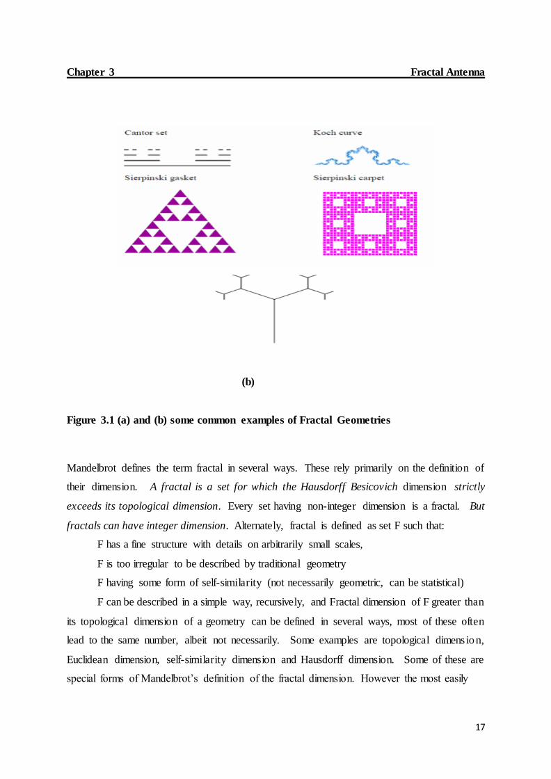
irregular nature. Some examples of fractals are given in Fig. 1.1. Most of these geometries
are infinitely sub-divisible, with each division a copy of the parent. This special nature of these
geometries has led to several interesting features uncommon with Euclidean geometry.
(a)
17
Chapter 3 Fractal Antenna
(b)
Figure 3.1 (a) and (b) some common examples of Fractal Geometries
Mandelbrot defines the term fractal in several ways. These rely primarily on the definition of
their dimension. A fractal is a set for which the Hausdorff Besicovich dimension strictly
exceeds its topological dimension. Every set having non-integer dimension is a fractal. But
fractals can have integer dimension. Alternately, fractal is defined as set F such that:
F has a fine structure with details on arbitrarily small scales,
F is too irregular to be described by traditional geometry
F having some form of self-similarity (not necessarily geometric, can be statistical)
F can be described in a simple way, recursively, and Fractal dimension of F greater than
its topological dimension of a geometry can be defined in several ways, most of these often
lead to the same number, albeit not necessarily. Some examples are topological dimens ion,
Euclidean dimension, self-similarity dimension and Hausdorff dimension. Some of these are
special forms of Mandelbrot’s definition of the fractal dimension. However the most easily

18
Chapter 3 Fractal Antenna
understood definition is for self-similarity dimension. To obtain this value, the geometry is
divided into scaled down, but identical copies of itself.
a. Sierpinski Gasket Geometry Sierpinski gasket geometry [1] is the most widely studied fractal geometry for antenna
applications. The steps for constructing this fractal are described.1st a triangle is taken in a
plane. Then in next step a central triangle is removed with vertices that are located at the
midpoint of the sides of the triangle as shown in the figure. The process is then repeated for
remaining triangles as shown in figure. The Sierpinski gasket fractal is formed by doing this
iterative process infinite number of times. Black triangular areas represent a metallic conductor
and the white triangular areas represent the region from where metals are removed.
Figure 3.2 Steps of construction of Sierpinski Gasket Geometry
19
Chapter 3 Fractal Antenna
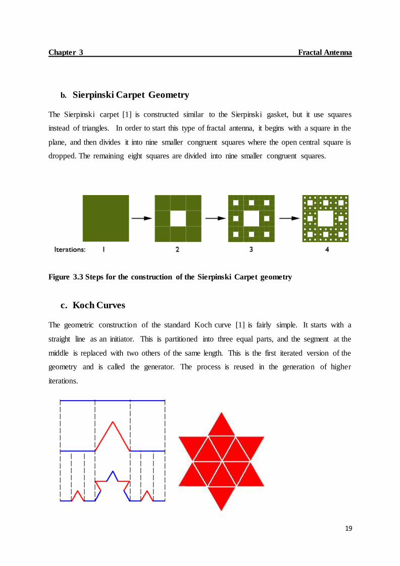
b. Sierpinski Carpet Geometry
The Sierpinski carpet [1] is constructed similar to the Sierpinski gasket, but it use squares
instead of triangles. In order to start this type of fractal antenna, it begins with a square in the
plane, and then divides it into nine smaller congruent squares where the open central square is
dropped. The remaining eight squares are divided into nine smaller congruent squares.
Figure 3.3 Steps for the construction of the Sierpinski Carpet geometry
c. Koch Curves The geometric construction of the standard Koch curve [1] is fairly simple. It starts with a
straight line as an initiator. This is partitioned into three equal parts, and the segment at the
middle is replaced with two others of the same length. This is the first iterated version of the
geometry and is called the generator. The process is reused in the generation of higher
iterations.

20
Chapter 3 Fractal Antenna
Figure 3.4 Steps for construction of the Koch curve geometry
d. The Cantor Set Geometry The Cantor Set [1] is created by the following algorithm. It starts with the closed interval [0,
1].
Figure 3.5 steps for construction of the Cantor set

21
Chapter 3 Fractal Antenna
Say it as set A1 or the 0th (initial) set. Delete the middle open third. This leaves a new set,
called A2 [0, 1/3] U [2/3, 1]. Each iteration through the algorithm removes the open middle
third from each segment of the previous iteration. Thus, the next two sets would be
A3[0,1/9]U[2/9,1/3]U[2/3,7/9]U[8/9,1] and according to the previous one A4 set will be A4
[0,1/27]U[2/27,1/9]U[2/9,7/27]U[8/27,1/3]U[2/3,19/27]U[20/27,7/9]U[8/9,25/27]U[26/27,1].
We can see that the set becomes sparser as the number of iteration increases. The Cantor Set is
defined to be the set of the points that remain as the number of iterations tends to infinity.

22
Chapter 4
FRACTAL MONOPOLE WIDEBAND ANTENNAS
4.1 Koch Fractal Curve Monopole Antenna
An antenna based on Koch Fractal geometry and Microstrip line feeding technique for
wideband wireless application is studied in this section .The Koch curve structure is applied to
the upper, bottom, left and right side of a rectangular patch. The impedance bandwidth of the
proposed model is 81.26% from 3.31-7.84 GHZ (2:1 VSWR BW).
4.1.1 Antenna Geometry
(a) (b) (c)
Figure 4.1 Geometry of the proposed Koch fractal antenna I (a) Front view (b) Back view
(c) substrate
The graphical representation of Koch curve is shown in Figure 4.1. The Geometry of the
proposed antenna is illustrated in Figure 4.3 with corresponding optimized parameters listed in
Table 4.1.Here, the Koch Fractal is considered in simple rectangular patch edges to expand the
antenna bandwidth. The proposed antenna is built on one side of FR-4 dielectric substrate
(thickness ts=1.6mm and relative permittivity εr=4.4) of 14×30.4×1.6mm^3. It is fed by 50Ω
Microstrip line feeding technique of 1.8×10×0.05mm^3 for the transmission line portion and

23
Chapter 4 Fractal monopole wideband antennas
1.1×5×0.05mm^3 for the quarter wave transformer portion. A first iteration of Koch Fractal
Geometry of iteration factor of 3 is applied to the rectangular patch of dimens ions
10×10×0.05mm^3. The proposed antenna uses a partial ground plane of dimens ions
14×12.9×0.05mm^3.
Table 4.1 Design parameters of the proposed Koch fractal Antenna
Length (L) Width (W) Height (H)
Ground plane 14 mm 12.9 mm 0.05 mm
Feed line Lq=1.1 mm
1.8 mm
Wq=5 mm
10 mm
0.05 mm
Patch 10 mm 10 mm 0.05 mm
Substrate 14 mm 30.4 mm 1.6 mm
Lq= Length of the quarter wave Transformer and
Wq=width of the quarter wave transformer
4.1.2 Simulation Results
1. Return loss
(a)

24
Chapter 4 Fractal monopole wideband antennas
(b)
Figure 4.2 Return loss (a) width of the ground plane (W=12.9mm) (b) W=13.9mm
2. Radiation pattern
(a)

25
Chapter 4 Fractal monopole wideband antennas
(b)
(c)
Figure 4.3 Radiation pattern (a) at 3.72 GHZ (b) at 5 GHZ (c) at 6.72 GHZ

26
Chapter 4 Fractal monopole wideband antennas
3. Surface Current distribution
(a) (b)
Figure 4.4. Current distribution (a) at 5GHZ (b) at 6.72GHZ
Figure 4.2 (a) shows the simulated reflection coefficients of the proposed antenna. Figure 4.2
(b) shows the simulated results due to change of the ground plane width (W).The width has a
prominent effect on the wideband operation of the proposed Fractal antenna. Although the
length of the ground plane has negligible effect, it is fixed in this case. It is observed that the
resonant frequency decreases with the increase in ground plane width for example, for
W=13.9 mm, the frequency range shifts from (3.31-7.84 GHZ) 8.26% to (3.43-7.14 GHZ)

27
Chapter 4 Fractal monopole wideband antennas
70.2%.When w=12.9 mm, the impedance bandwidth is well matched bellow -10Db and
covers the desired operating bandwidth.
Figure 4.3 and Figure 4.4 illustrate the simulated 2D radiation patterns and surface current
distribution of the proposed antenna at 3.72 GHZ, 5GHZ and 7GHZ. It shows that the
patterns are omnidirectional in nature for wideband frequency.
Frequency 3.72 GHZ 4.2 GHZ 5 GHZ 6 GHZ 6.72 GHZ 7 GHZ
Return
loss (dB)
-14.68 -19.33 -17.9 -15.53 -12.02 -10.75
Gain (dB) 2.58 2.80 3.17 3.58 3.76 3.66
Efficiency 87.61% 88.34% 86.94% 85.94% 82.9% 80.37%
Table 4.2 Measured Gain, Return loss and total simulated Efficiency
4.2 Modified Koch Fractal Curve Monopole Antenna
A modified version of the previous fractal antenna based on Koch Fractal geometry and
Microstrip line feeding technique for wideband wireless application is presented here .The
Koch curve structure is added on the rectangular patch. The impedance bandwidth of the
proposed model is improved from 81.26% (3.31-7.84 GHZ) to 85.37% from 3.31-8.24 GHZ
(2:1 VSWR BW).

28
Chapter 4 Fractal monopole wideband antennas
4.2.1 Antenna Geometry
(a) (b) (c)
Figure 4.5 Geometry of the modified Koch antenna (a) Front view (b) Back view (c) substrate
The graphical representation of the Koch curve is shown in Figure 4.5. The designed and
optimized parameters are listed in Table 4.1. The proposed antenna is built on one side of FR-
4 dielectric substrate (thickness ts=1.6mm and relative permittivity εr=4.4) of
16×30.4×1.6mm^3. It is fed by 50Ω Microstrip line feeding technique of 1.8×10×0.05mm^3
for the transmission line portion and 1.1×5×0.05mm^3 for the quarter wave transformer
portion. A first iteration of Koch Fractal Geometry of iteration factor of 3 is applied to the
rectangular patch of dimension 10×10×0.05mm^3. The proposed antenna uses a partial ground
plane of dimensions 16×12.9×0.05mm^3.
Table 4.3 design parameters of the modified Koch fractal Antenna
Length (L) Width (W) Height (H)
Ground plane 16 mm 12.9 mm 0.05 mm
Feed line Lq=1.1 mm
1.8 mm
Wq=5 mm
10 mm
0.05 mm
Patch 10mm 10mm 0.05mm
Substrate 16 mm 30.4 mm 1.6 mm
Lq= Length of the quarter wave Transformer and
Wq=width of the quarter wave transformer

29
Chapter 4 Fractal monopole wideband antennas
4.2.2 Simulation Results
1. Return loss
(a)
(b)
Figure 4.6 Return loss (a) width of the ground plane (W=12.9mm) (b) W=13.9mm

30
Chapter 4 Fractal monopole wideband antennas
2. Radiation pattern
(a)
(b)
31
Chapter 4 Fractal monopole wideband antennas
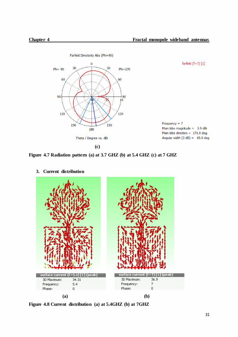
(c)
Figure 4.7 Radiation pattern (a) at 3.7 GHZ (b) at 5.4 GHZ (c) at 7 GHZ
3. Current distribution
(a) (b)
Figure 4.8 Current distribution (a) at 5.4GHZ (b) at 7GHZ

32
Chapter 4 Fractal monopole wideband antennas
Frequency 3.7GHZ 4.5 GHZ 5.4 GHZ 6 GHZ 7 GHZ 7.5 GHZ
Return
loss (dB)
-12.3 -11.76 -14.35 -19.44 -17.45 -13.88
Gain (dB) 1.96 2.22 2.75 3.1 3.2 3.05
Efficiency 87.4 85.14 87.57 90 89.38 85.6
Table 4.4 Measured Gain, Return loss and total simulated Efficiency
4.3 Hybrid Fractal Monopole Antenna
This section presents a new antenna structure based on two fractal geometries for wideband
wireless applications which is realised by the combination of Koch curve and the sierpinski
carpet geometry. The basic antenna is a rectangular shape as described earlier. The proposed
model exhibits a bandwidth of 85.02% in the range 3.3-8.18 GHZ (2:1 VSWR BW).
The measured bandwidth meets the requirements of many commercial bands such as WI-FI
802.11y (3.6-3.7GHZ), WiMAX (3.4-3.6 GHZ and 3.7-4.2 GHZ) and WLAN 802.11(5.31-
6.32 GHZ).
4.3.1 Antenna Geometry
(a) (b) (c)
Figure 4.9 Geometry of the Hybrid Fractal Antenna (a) Front view (b) Back view (c) substrate

33
Chapter 4 Fractal monopole wideband antennas
The recursive procedure of the Koch curve and the sierpinski fractal is shown in Figure 4.9.
The Koch curve is added to a rectangular patch is explained for the previous fractal antenna
with the same dimensions. The Hybrid fractal antenna optimizes the size of the antenna and
enhances the bandwidth as well.
The design is fabricated using FR-4 board with relative permittivity, εr= 4.4, substrate
thickness, t = 1.6mm and tangent loss, tan δ = 0.019 where the radiating element is the cooper
clad.
The iteration of the sierpinski fractal geometry from zero stage until second stage is shown
below:
Figure 4.10 stages iteration of the sierpinski geometry used in the design
Table 4.5 design parameters of the sierpinski fractal geometry
Length (L) Width (W) Height(H)
Iteration 0 10mm 10mm 0.05mm
Iteration 1 5mm
5mm 0.05mm
Iteration 2 1.1mm 1.1mm 0.05mm

34
Chapter 4 Fractal monopole wideband antennas
4.3.2 Simulation Results
1. Return loss
Figure 4.11 Return loss
2. Radiation pattern
(a)

35
(b)
(c)
Figure 4.12 Radiation pattern (a) at 3.7 GHZ (b) at 5.4 GHZ (c) at 7 GHZ

36
Chapter 4 Fractal monopole wideband antennas
4.3.2 Surface Current
(a) (b)
Figure 4.13 Current distribution (a) at 5.4GHZ (b) at 7GHZ
Figure 4.12 and Figure 4.13 illustrate the simulated 2D radiation patterns and surface current
distribution of the proposed antenna at 3.72 GHZ, 5GHZ and 7GHZ. It shows that the patterns
are omnidirectional in nature for wideband frequency. The patterns describes the behaviour of
the antenna’s direction and gain. The surface current distribution shows the different modes of
propagation as well as the variation of the resonant frequency.
Frequency 3.7GHZ 4.2 GHZ 5.4 GHZ 6.5 GHZ 7 GHZ 7.9 GHZ
Return
loss (dB)
-12.1 -11.54 -14.1 -25.0 -19.83 -11.65
Gain (dB) 1.97 2.1 2.77 3.34 3.27 3.4
Efficiency 86.72 84.76 86.94 90.73 89.64 80.72
Table 4.6 Measured Gain, Return loss and total simulated Efficiency

37
Chapter 4 Fractal monopole wideband antennas
4.4 Inscribed triangle circular Fractal Antenna
An inscribed triangle Fractal antenna is presented here for wideband applications. The antenna
has been designed on a substrate FR-4 with permittivity εr=4.4 and thickness ts=1.6mm with
an initial diameter of 30mm.The antenna exhibits a bandwidth from 3.37-6.53 GHZ (63.8%)
Impendence bandwidth at VSWR 2:1.This wideband characteristic is achieved by using a
Microstrip line feeding technique.
4.4.1 Antenna geometry
(a) (b)
Figure 4.14 Geometry of the inscribed triangle circular Fractal antenna
A Fractal Monopole antenna with a Microstrip feed of 10 mm radius is shown in Figure 4.14.
Fractal Geometry with each iteration has been constructed from monopole circular disc of 10
mm radius. In the first iteration, four regular polyhedrons of size 2.856 mm has been taken
inside the circle of radius 10mm and each polyhedron is rotated with an angle 30 degree. These
four polyhedrons were subtracted from the 10 mm circle radius. This is called 1st iteration. In
2nd iteration, a circle of 5.8mm radius has been taken inside these four polyhedrons. In this 5.8
mm radius circle, four polyhedron of size 2.1 mm has been taken again and each polyhedron
is rotated with an angle of 30 degree then this four polyhedrons were subtracted from 5.8 mm
circle radius resulting in the second iteration.

38
Chapter 4 Fractal monopole wideband antennas
Table 4.7 Design parameters of the inscribed triangle circular fractal antenna
4.4.2 Results
1. Return loss
(a)
Figure 4.15 Return loss of the inscribed circular Fractal antenna
Length (L) Width (W) Height(H) Radius
Substrate 22mm 22mm 1.6mm
Ground plane 22 mm
3mm 0.05mm
Feed line 3mm 4.8mm 0.05mm
Patch 0.05mm 10mm

39
Chapter 4 Fractal monopole wideband antennas
4.4.2 Radiation pattern
(a)
(b)

40
(c)
Figure 4.16 Radiation pattern (a) at 3.89 GHZ (b) at 4.82 GHZ (c) at 5.8 GHZ
4.4.3 Surface current
(a) (b)
Figure 4.17 Current distribution (a) at 3.89GHZ (b) at 5.8GHZ

41
Chapter 4 Fractal monopole wideband antennas
Frequency 3.7GHZ 3.89 GHZ 4.83 GHZ 5 GHZ 5.8 GHZ 6.4 GHZ
Return
loss (dB)
-18.73 -23.95 -14.53 -14.79 -23.97 -11.8
Gain (dB) 2.67 2.82 3.21 3.34 4.1 4.25
Efficiency 100.95 102.45 99.17 99.22 101.07 93.23
Table 4.8 Measured Gain, Return loss and total simulated Efficiency
Koch Fractal
antenna I
Modified Koch
Fractal antenna
Hybrid Fractal
antenna
Inscribed
circular Fractal
antenna
Dimensions(mm) 14×30.4×1.6 16×30.4×1.6 16×30.4×1.6 22×22×1.6
Impedance
Bandwidth(GHZ)
3.31~7.84 3.31 ~ 8.24 3.3~8.18 3.37~6.53
Impedance
Bandwidth (%)
81.26% 85.5% 85.01% 63.8%
Gain (dB) 2.58~3.66 1.96~3.05 1.97~3.4 2.67~4.25
Efficiency (%) ~83.2% ~87.5% ~86.7% ~95.5%
Table 4.9 comparison study of the different wideband Fractal antennas proposed.

42
Chapter 5
CONCLUSUION AND FUTURE WORK
5.1 Conclusion
This thesis describe the development of different wideband fractal Monpole antennas to
achieve low profile and ease of integration. The aim of the design is to reduce the physical
antenna size and increase the impedance bandwidth .The Koch curve fractal antenna is
designed for wideband wireless application and covers an impedance bandwidth of 81.26%
from 3.31-7.84 GHZ. The peak gain of 4.4 dB is achieved with a total efficiency of 80%.
The proposed Hybrid Fractal antenna model exhibits a bandwidth of 85.02% in the range 3.3-
8.18 GHZ (2:1 VSWR BW).The measured bandwidth meets the requirements of many
commercial bands such as WI-FI 802.11y (3.6-3.7GHZ), WiMAX (3.4-3.6 GHZ and 3.7-4.2
GHZ) and WLAN 802.11(5.31-6.32 GHZ).
For further understanding of the behaviour of the proposed antennas, Surface current
Distribution and 2D Radiation patterns are presented.
The Simulated results have confirmed wideband behaviour of the proposed antennas with a
nearly omnidirectional radiation properties over the entire frequency band of interest. These
features make them attractive for future communication systems.
5.2 Future work
In this thesis different types of compact fractal antennas are studied for wideband operation.
Based on this, future work may be carried out such as
The effect of material properties on Fractal antenna performance such as gain,
efficiency, radiation patterns, etc. can be studied.
Study of new techniques to reduce the size and enhance the bandwidth of fractal
wideband antennas for use in mobile and portable devices.
Fabrication of the proposed Fractal antennas and comparison of simulated Results with
the measured Results.
43
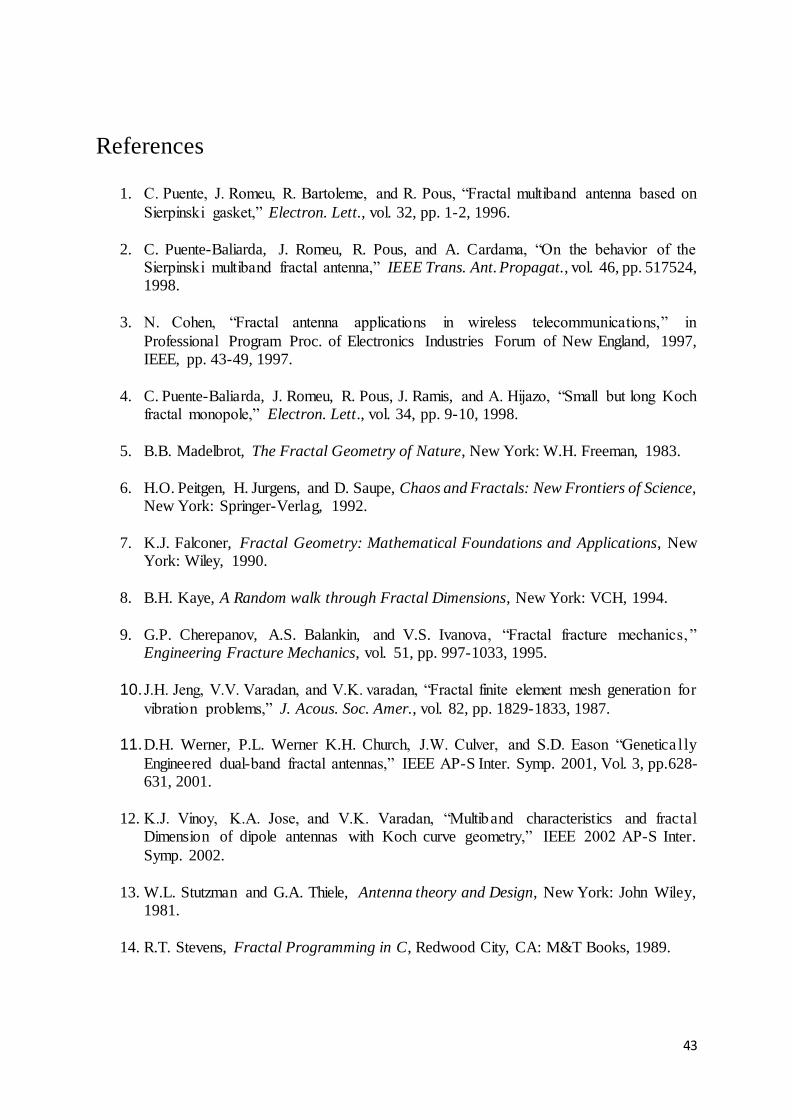
References
1. C. Puente, J. Romeu, R. Bartoleme, and R. Pous, “Fractal multiband antenna based on
Sierpinski gasket,” Electron. Lett., vol. 32, pp. 1-2, 1996.
2. C. Puente-Baliarda, J. Romeu, R. Pous, and A. Cardama, “On the behavior of the Sierpinski multiband fractal antenna,” IEEE Trans. Ant. Propagat., vol. 46, pp. 517524, 1998.
3. N. Cohen, “Fractal antenna applications in wireless telecommunications,” in
Professional Program Proc. of Electronics Industries Forum of New England, 1997, IEEE, pp. 43-49, 1997.
4. C. Puente-Baliarda, J. Romeu, R. Pous, J. Ramis, and A. Hijazo, “Small but long Koch fractal monopole,” Electron. Lett., vol. 34, pp. 9-10, 1998.
5. B.B. Madelbrot, The Fractal Geometry of Nature, New York: W.H. Freeman, 1983.
6. H.O. Peitgen, H. Jurgens, and D. Saupe, Chaos and Fractals: New Frontiers of Science, New York: Springer-Verlag, 1992.
7. K.J. Falconer, Fractal Geometry: Mathematical Foundations and Applications, New York: Wiley, 1990.
8. B.H. Kaye, A Random walk through Fractal Dimensions, New York: VCH, 1994.
9. G.P. Cherepanov, A.S. Balankin, and V.S. Ivanova, “Fractal fracture mechanics, ” Engineering Fracture Mechanics, vol. 51, pp. 997-1033, 1995.
10. J.H. Jeng, V.V. Varadan, and V.K. varadan, “Fractal finite element mesh generation for
vibration problems,” J. Acous. Soc. Amer., vol. 82, pp. 1829-1833, 1987.
11. D.H. Werner, P.L. Werner K.H. Church, J.W. Culver, and S.D. Eason “Genetica l ly
Engineered dual-band fractal antennas,” IEEE AP-S Inter. Symp. 2001, Vol. 3, pp.628-631, 2001.
12. K.J. Vinoy, K.A. Jose, and V.K. Varadan, “Multiband characteristics and fractal
Dimension of dipole antennas with Koch curve geometry,” IEEE 2002 AP-S Inter.
Symp. 2002.
13. W.L. Stutzman and G.A. Thiele, Antenna theory and Design, New York: John Wiley, 1981.
14. R.T. Stevens, Fractal Programming in C, Redwood City, CA: M&T Books, 1989.

44
15. K.J. Vinoy, K.A. Jose, V.K. Varadan, and V.V. Varadan, “Hilbert curve fractal Antenna: a small resonant antenna for VHF/UHF applications,” Microwave &Optical
Technology Letters, vol. 29, pp. 215-219, 2001.
16. H.-O. Peitgen, J.M. Henriques, L.F. Penedo (Eds.), Fractals in the Fundamental and Applied Sciences, Amsterdam: North Holland, 1991.
17. C.T.P. Song, P.S. Hall, H. Ghafouri-Shiraz and D. Wake, “Sierpinski monopole Antenna with controlled band spacing and input impedance,” Electron. Lett., vol. 35,
pp. 1036-1037, 1999.
18. J. Yeo and R. Mittra, “Modified Sierpinski gasket patch antnna for multi-band
Applications,” IEEE AP-S Inter. Conf. 2001, Vol. 3, pp. 134-147, 2001.
19. V.K. Varadan, K.A. Jose, V.V. Varadan, R. Hughes, and J.F. Kelley, “Novel Microwave planar phase shifter,” Microwave J., vol 38, 1995.
20. K.A. Jose, V.K. Varadan, and V.V. Varadan, “Electronically tunable microstripPa tch antenna,” Microwave Opt. Technol. Lett., vol. 20, pp. 166-169, 199.