Design and Analysis of Axial Flux Permanent Magnet ... · In this report 200W, 16.66A and 719rpm...
21
© 2017 IJRTI | Volume 2, Issue 9 | ISSN: 2456-3315 IJRTI1709014 International Journal for Research Trends and Innovation (www.ijrti.org ) 70 Design and Analysis of Axial Flux Permanent Magnet Generator for Low Wind Power Application 1 S.S. Bageshwar, 2 P. V. Phand 1 Assistant Professor, 2 P.G. Student Department of Electrical power system, T.S.S.M’s BSCOER narha, Pune, India. Abstract—An axial flux permanent magnet (AFPM) machine with single rotor and single air-cored stator is studied in this project. An improved design of an ironless axial flux permanent magnet synchronous generator (AFPMSG) is presented for direct-coupled wind turbine application. The design for a low-speed, direct-drive, axial flux permanent magnet (AFPM) generator with a coreless stator and rotor that is intended for application to small wind turbine power generation systems. The main focus of this study is to improve the power output and efficiency of wind power generation by investigating the electromagnetic and structural features of a coreless AFPM generator. The design is validated by comparing the performance achieved with a prototype. The results of our comparison demonstrate that the proposed generator has a number of advantages such as a simpler structure, higher efficiency over a wide range of operating speeds, higher energy yield, lighter weight and better power utilization than conventional machines. The design and manufacturing processes for coreless axial flux permanent magnet generators are described for low cost rural electrification applications, where local production of small wind turbines is considered. Finally, a prototype machine is fabricated, and experiments are carried out to test its performances by comparing with design topology. IndexTerms—AFPM, AFPMSG. I. INTRODUCTION Since generation of electricity is becoming very important and sensitive issue day by day. As we know wind energy is one of the cleanest, free and cheapest forms of energy. Wind energy is playing a vital role in generation of electricity, mostly in small scale residential or rural areas where electricity is not easily reachable. So the selection of economical and efficient wind generator is become very important topic for research now a days. Therefore many literatures were published on design and analysis of Axial Flux Machines (AFMs).The diverse studies shows that AFMs are become very attractive and cost effective alternatives for Radial Flux machines (RFMs) especially for applications such as small wind power system, aircrafts, compact engine generator sets, hybrid electric vehicles and direct battery charging. Axial Flux Permanent Magnet (AFPM) machine size and shape are important features in applications where space is limited, so compatibility is crucial. Since PM machines are increasingly become very dominant machines with cost competitiveness of high energy PMs such as Neodymium Iron boron (Nd2Fe14).They are usually more efficient because of the fact that field excitation losses are eliminated resulting in significant rotor loss reduction. Hence the generator efficiency is improved and high power density is achieved. AFPM machines have no’s of advantages over Radial Flux Permanent Magnet (RFPM) machines such as they have high power to weight ratio, high aspect ratio, reduced noise and vibration levels, adjustable air gaps and occupies less space etc., AFPM generators are most suitable than radial flux PM generators for small wind power applications. In this report 200W, 16.66A and 719rpm Axial Flux Permanent Magnet (AFPM) generator’s design and fabrication is discussed. Testing of AFPM generator is done in Electrical Machine laboratory, the result of the same are also included here. This report also includes various configurations of AFPM machines and comparison between them. II. EXISTING SYSTEM WITH LIMITATIONS Since there are no’s of conventional PM generators are available for converting wind energy into electrical energy such as radial flux PM generators(synchronous or asynchronous, induction generators etc. But these conventional Radial Flux PM(RFPM) generators have no’s of disadvantages as compared to AFPM generator such as they have low power density ,low torque, high cos t, high cogging torque, less efficiency, fixed air gaps, high noise and vibration levels ,low torque to weight ratio and large in size etc.The slotted or non-slotted RFPM generators are also available .But the non-slotted RFPM generator has small aspect ratio (Diameter to length) results in high core losses. One advantage of this RFPM generator over AFPM generator is that they have better heat transfer. III. VARIOUS TOPOLOGIES OF AFPM MACHINES AFPM machines were first introduced in late 70s (Campbell, 1975)Growing interest in AFPM machines in several applications due to their high torque-to-weight ratio and efficiency as an alternative to conventional radial-flux machines was significant in the last decade. Axial flux machines are formed by a rotor disc produce an axial flux and a stator disc containing the phase windings. Many
Transcript of Design and Analysis of Axial Flux Permanent Magnet ... · In this report 200W, 16.66A and 719rpm...

© 2017 IJRTI | Volume 2, Issue 9 | ISSN: 2456-3315
IJRTI1709014 International Journal for Research Trends and Innovation (www.ijrti.org) 70
Design and Analysis of Axial Flux Permanent
Magnet Generator for Low Wind Power Application
1S.S. Bageshwar,
2P. V. Phand
1Assistant Professor, 2P.G. Student
Department of Electrical power system,
T.S.S.M’s BSCOER narha, Pune, India.
Abstract—An axial flux permanent magnet (AFPM) machine with single rotor and single air-cored stator is studied in this
project. An improved design of an ironless axial flux permanent magnet synchronous generator (AFPMSG) is presented
for direct-coupled wind turbine application. The design for a low-speed, direct-drive, axial flux permanent magnet
(AFPM) generator with a coreless stator and rotor that is intended for application to small wind turbine power generation
systems. The main focus of this study is to improve the power output and efficiency of wind power generation by
investigating the electromagnetic and structural features of a coreless AFPM generator. The design is validated by
comparing the performance achieved with a prototype. The results of our comparison demonstrate that the proposed
generator has a number of advantages such as a simpler structure, higher efficiency over a wide range of operating
speeds, higher energy yield, lighter weight and better power utilization than conventional machines. The design and
manufacturing processes for coreless axial flux permanent magnet generators are described for low cost rural
electrification applications, where local production of small wind turbines is considered. Finally, a prototype machine is
fabricated, and experiments are carried out to test its performances by comparing with design topology.
IndexTerms—AFPM, AFPMSG.
I. INTRODUCTION
Since generation of electricity is becoming very important and sensitive issue day by day. As we know wind energy is one of
the cleanest, free and cheapest forms of energy. Wind energy is playing a vital role in generation of electricity, mostly in small
scale residential or rural areas where electricity is not easily reachable. So the selection of economical and efficient wind generator
is become very important topic for research now a days. Therefore many literatures were published on design and analysis of Axial Flux Machines (AFMs).The diverse studies shows that AFMs are become very attractive and cost effective alternatives for Radial
Flux machines (RFMs) especially for applications such as small wind power system, aircrafts, compact engine generator sets,
hybrid electric vehicles and direct battery charging.
Axial Flux Permanent Magnet (AFPM) machine size and shape are important features in applications where space is limited, so
compatibility is crucial. Since PM machines are increasingly become very dominant machines with cost competitiveness of high
energy PMs such as Neodymium Iron boron (Nd2Fe14).They are usually more efficient because of the fact that field excitation
losses are eliminated resulting in significant rotor loss reduction. Hence the generator efficiency is improved and high power
density is achieved. AFPM machines have no’s of advantages over Radial Flux Permanent Magnet (RFPM) machines such as they have high power to weight ratio, high aspect ratio, reduced noise and vibration levels, adjustable air gaps and occupies less space
etc., AFPM generators are most suitable than radial flux PM generators for small wind power applications.
In this report 200W, 16.66A and 719rpm Axial Flux Permanent Magnet (AFPM) generator’s design and fabrication is discussed. Testing of AFPM generator is done in Electrical Machine laboratory, the result of the same are also included here. This report also
includes various configurations of AFPM machines and comparison between them.
II. EXISTING SYSTEM WITH LIMITATIONS
Since there are no’s of conventional PM generators are available for converting wind energy into electrical energy such as radial
flux PM generators(synchronous or asynchronous, induction generators etc. But these conventional Radial Flux PM(RFPM)
generators have no’s of disadvantages as compared to AFPM generator such as they have low power density ,low torque, high cost,
high cogging torque, less efficiency, fixed air gaps, high noise and vibration levels ,low torque to weight ratio and large in size
etc.The slotted or non-slotted RFPM generators are also available .But the non-slotted RFPM generator has small aspect ratio (Diameter to length) results in high core losses. One advantage of this RFPM generator over AFPM generator is that they have
better heat transfer.
III. VARIOUS TOPOLOGIES OF AFPM MACHINES
AFPM machines were first introduced in late 70s (Campbell, 1975)Growing interest in AFPM machines in several applications due
to their high torque-to-weight ratio and efficiency as an alternative to conventional radial-flux machines was significant in the last
decade. Axial flux machines are formed by a rotor disc produce an axial flux and a stator disc containing the phase windings. Many

© 2017 IJRTI | Volume 2, Issue 9 | ISSN: 2456-3315
IJRTI1709014 International Journal for Research Trends and Innovation (www.ijrti.org) 71
variations in this basic design are possible, including single-sided, double-sided, torus, and multi-disc designs. Fig1. Shows various
AFPM topologies.
Fig. 1 various topologies of AFPM Machines
Proposed/selected topology
Fig 2 shows the simples and basic structure of AFPM Machines. Single stator and single rotor AFPM machine has a PM disc rotor
mounted on the rotor surface and coreless stator winding immersed in epoxy resin. The magnetic force may twist the structure very
easily. It is subject to unbalanced axial force between rotor and stator, so, does not like structures with balanced axial forces, it
requires more-complex bearing arrangements and thicker rotor disk.
Fig. 2. Single stator single rotor AFPM topology
IV. BASIC OPERATING PRINCIPLE
According to faraday’s law of electromagnetic induction, “Any change in the magnetic flux passing through coil, will
induce a voltage in that coil”.
More rapid movement or stronger flux induces a higher voltage in each turn of each coil. The no. of coil turns, flux & rpm
are factors on which the voltage produced by the coil is depends.
At low speed the coil will produce low voltage. When turbine reaches a certain cut-in speed, the voltage is become a
nearly enough to charge a battery. Only when the speed is above the cut-in speed the stator feeds current into the battery.
Generally the electrical output of the turbine will depend upon the strength of the wind and the size of the blades. The
blades produce mechanical energy that is converted to electricity by alternator.
V. BASIC SELECTIONS
The manufacture of the generator that will meet the requirements requires careful selection of generator configuration, material and
manufacturing methods. The materials were selected based on two major criteria: availability and cost. To fulfill these criteria often
means that the generator efficiency has to be sacrificed. The Following are the measures implemented to achieve economical cost:
How Big?
The amount of energy that you will get from the turbine depends mostly on the two things: The diameter of the blade rotor and the
exposure to good winds. The power rating of the alternator in watts actually has very little influence most of time, because full
rated power is only available in stronger winds. The rest of time the power is limited by wind and size & weight of rotor. I have
decided to design AFPM for turbine diameter 1200mm, 12V and approximate power rating 30W.
Permanent magnets
The rare earth magnets, SmCo and NdFeB, have become popular because of their greater power density, high coercivity, high flux
densities and the linearity of their demagnetization curves. NdFeB is preferred because it is cheaper and more readily available.
Therefore, NdFeB magnets are selected for use in Permanent Magnet Generator (PMG), with some conservatively assumed values.
Stator & Rotor discs One stator disc and one rotor disc is decided to use for making proposed AFPM generator. Stator disc is an assembly of coils
emerged in epoxy resin and rotor is a magnet disc.
© 2017 IJRTI | Volume 2, Issue 9 | ISSN: 2456-3315
IJRTI1709014 International Journal for Research Trends and Innovation (www.ijrti.org) 72
Material and Tool Selection
All materials and tools used in the construction of generator need to be easily sourced and at low costs. Stator & rotor
moulds are ideal for low cost application.
These materials can be easily found anywhere in Maharashtra for exp. In Bhumi Enterprises in pune and wood workshops.
Stainless steel disks need to be cut with plasma pantograph router are available in Shalimar Engineers, pune
Bearing hub required for rotation of generator is a car or trailer hub which can be found in Proton Metal crafts Private
Limited,Pune.
Finally the neodymium magnets (NdFeB) which are the stronger magnets for less volume when compared to Ferro magnet
are available JR Strong Magnet Pvt. Ltd,Pune
Polyster resin is a material that can provide support for the stator coils which lay in the air and protection from corrosion
for the magnets. It is available in Gayatree Polymers Private Limited, Pune.
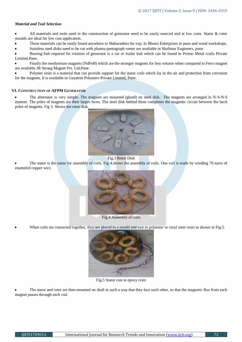
VI. CONSTRUCTION OF AFPM GENERATOR
The alternator is very simple. The magnets are mounted (glued) on steel disk. The magnets are arranged in N-S-N-S
manner. The poles of magnets are their larges faces. The steel disk behind them completes the magnetic circuit between the back
poles of magnets. Fig 3. Shows the rotor disk.
Fig.3 Rotor Disk
The stator is the name for assembly of coils. Fig 4.shows the assembly of coils. One coil is made by winding 76 turns of
enameled copper wire.
Fig.4 Assembly of coils
When coils are connected together, they are placed in a mould and cast in polyester or vinyl ester resin as shown in Fig.5.
Fig.5 Stator cast in epoxy resin
The stator and rotor are then mounted on shaft in such a way that they face each other, so that the magnetic flux from each
magnet passes through each coil.

© 2017 IJRTI | Volume 2, Issue 9 | ISSN: 2456-3315
IJRTI1709014 International Journal for Research Trends and Innovation (www.ijrti.org) 73
VII. BLOCK DIAGRAM OF AFPM GENERATOR
Fig. 6 shows block diagram representation of AFPM generator, as we can see we can rectify the output voltage of generator to charge the battery. Further we can use bridge inverter to achieve AC voltage, and then we can increase the voltage magnitude by
using step up transformer.
Fig.6. Block diagram representation of AFPM generator
Literature Survey
Wind power, considered as one of the cleanest renewable energies, is now receiving more and more attention. In some developing
countries like China, with the supportive policies of the government, the utility of wind power is growing fast. Many wind power
stations with large scale wind turbines have been built to provide electricity to the grid in places with good wind resources.
However, in some remote but windy areas where grid is not available, small low-speed stand-alone high-efficiency wind generators
can be very attractive for household electrical appliance as well as outdoor monitor equipments. So the selection of economical and
efficient wind generator is become very important topic for research now a days. Therefore many literatures were published on
design and analysis of Axial Flux Machines (AFMs).The diverse studies shows that AFMs are become very attractive and cost
effective alternatives for Radial Flux machines (RFMs) especially for applications such as small wind power system, aircrafts, compact engine generator sets, hybrid electric vehicles and direct battery charging.The authors described different axial gap
permanent magnet generators are designed and compared for one of the Caterpillar truck applications. Various axial gap designs
with multiple stators and rotors are carried out and compared with a conventional PM generator in terms of torque density,
efficiency, loss, heat dissipation, volume, inertia and weight. The results reveal the advantages of axial gap generators over radial
gap generators and that internal rotor double stator disc generator fits the hybrid electric traction application with the given
specifications.[1]
Design and manufacturing processfor coreless axial flux permanent magnet generators are described for low cost rural
electrification applications, where local production of small wind turbines is considered.Thedesign was made using basic
theoretical tools, simple programming methods, partially open source software, and simple manufacturing techniques.[2]The
design, manufacturing process and performance results of a low cost permanent magnet generator for small wind application is
described by author. Also mentioned that PM generators are able to achieve high efficiency compared with other generator types,
but they also cost more than other generators. To make PM generators a low cost option, the generator configuration and materials
have to be carefully selected. The authors described highlights on why the selected generator is designed, the choices made and the
effect of used materials and manufacturing process on efficiency and energy yield. [3]
Axial flux permanent magnet machines today are important technology in many applications, where they are alternative to the
radial flux permanent magnet machines. The review of the different topologies of axial flux permanent magnet generator and
advances/trends in axial flux PM machines in aspect of construction, features, modeling, simulation, analysis and design procedure are described and analyzed with the help of 2D and 3D FEA tool.[4]The description of an axial flux permanent magnet (AFPM)
machine with dual rotors and single air cored stator design is given in analytical form and the generator is applied for vertical shaft
small power off grid wind generating system. A 1KW, 300 rpm, air cored outer rotor surface mounted AFPM is designed and
analyzed. A 2- dimensional (2D) finite element analysis (FEA) method with sufficient accuracy is proposed to solve magnetic field
inside the AFPM generator. This method simplifies the modeling and reduces the time of computation. Besides, analytical method
is also presented to compute the air gap flux density (or magnetic field) of the generator.[5]
Since the Small-scale wind power applications require a cost effective and mechanically simple generator in order to be a reliable
energy source. For such applications, characterized by low speed of rotation, the axial flux permanent magnet generator is
particularly suited, since it can be designed with a large pole number and high torque density. The work on an axial flux permanent
magnet synchronous generator, double sided with internal rotor and slotted stators is done by the authors . Such a structure gives a
good compromise between performance characteristics and feasibility of construction. The design process of the machine is
described and validated by test experiments. [7-8]The complete details of how to build six different sizes of Axial flux permanent
magnet wind generator choosing between four or more voltages is described by the author in detail. Since everything such as how
to make assumptions, approximately which size can produce how much power and voltage, manufacturing process of all AFPM
generators, their installation and design procedure is described in detail with the help of mathematical formulas by the author. [9]
The authors mentioned the study of the magnetic field distribution in a two-rotor, permanent magnet, and ironless stator axial field
generator for direct-drive wind energy conversion.[10]This generator uses trapezoidal shaped magnets rather than circular magnets
PROPOSED
AFPM
GENERATOR
3 PHASE
BRIGDE
RECTIFIER
BRIDGE
INVERTE
R
LOAD TURBINE
ROTOR/PRIME
MOVER
BATEERY
(12V)
STEP-UP TRANSFOR
MER

© 2017 IJRTI | Volume 2, Issue 9 | ISSN: 2456-3315
IJRTI1709014 International Journal for Research Trends and Innovation (www.ijrti.org) 74
which allows the active area of the generator to be decoupled from its diameter, allowing a more compact machine to be built. A
spreadsheet design procedure has been developed .The authors also described how this generator can be used to control turbine
speed in strong winds. This is achieved by introducing an additional resistive dump load on the electrical output of the generator.
Simulation of this strategy has also shown [11]Axial-flux permanent-magnet machines today are important technology in many
applications, where they are an alternative to radial-flux permanent-magnet machines. 12]
Because the efficiency of the machine is important, specific measures are taken in order to reduce losses in the machine: thin
laminated grain oriented material in the teeth, concentrated pole windings, and segmented magnets. [13]The performance of a
coreless stator axial flux permanent magnet generator is calculated by using hybrid method which uses combination of finite
element analysis (FEA) and theoretical analysis.
AFPM Generator design
In this paper the design of single stator single rotor AFPM generator is done mathematically. For designing the generator some
assumptions are made first and then start designing the generator step by step. Following is the procedure of design.
I. CHOOSE WHAT TO DO/ ASSUMPTIONS:
Following table shows the parameters which were assumed and used in the design calculations of AFPM generator:
Table 1) Assumptions Made
Sr.no. Parameter Considered Value
1 Turbine Diameter(Td) 1200mm
2 Power rating 200w
3 Tip speed ratio(λ) 6.25
4 Cut-in wind speed(Vw cut-in) 3 m/s
5 rated wind speed (Vw rated) 11.45 m/s
6 Power coefficient (Cp) 0.35
7 Application /load Battery Charging(12V)
8 No. of phases Three phase
9 Frequency(F) 20 Hz
10 Coil Fill factor(Kf) 0.55
11 Saturation coefficient(ksat) 1
12 Vaccum Permeability(µ 4ᴨ x 10^-7
13 Generator Topology single stator(coreless)single rotor (steel disk)
14 Rectifier Three phase brige rectifier
15 Stator Outer diameter(Sdo) 293 mm
16 Stator Inner Diameter(Sdi) 85 mm
17 Rotor outer diameter(Rdo) 293 mm
18 rotor inner diameter(Rdi) 112 mm
19 purpose for M.E. Project
20 Input device/prime mover high speed AC cooler motor with blue common(200w,1500
rpm)
21 testing parameters Speed & voltage
22 testing location In college machine laboratory
The above assumptions are made by taking reference of various design literatures published before. Again following two
assumptions were used for the design calculations:
1) The magnetic flux density crosses the air gap perpendicularly.
2) The effects of space harmonics of the magnetic flux density distribution in the air gap are neglected; only the fundamental
is considered to contribute to power.
II. DESIGN CALCULATIONS:
Calculating the Blade/ Turbine rotor RPM (N):
The blade rotor speed is calculated by using following formula,
Ncut-in =(λ∗Vw cut −in∗60)
(Td∗3.1415 )

© 2017 IJRTI | Volume 2, Issue 9 | ISSN: 2456-3315
IJRTI1709014 International Journal for Research Trends and Innovation (www.ijrti.org) 75
Ncut-in =(6.25∗3∗60)
(1.2∗3.1415 )
Ncut-in = 298.42 rpm
Approximately 300 rpm is considered to design generator.
Aerodynamic power/Blade power (W):
Theoretical power contained in the wind is calculated as
Pair = 1
2 * ƍ * A* 𝑉3
Where ƍ= air density at sea level= 1.225 kg/m3(constant)
A= Sweapt area
A= ᴨ𝑟2
=3.1415*(𝑇𝑑
2)2
=3.1415*(1.2
2)2
= 1.1309 m2
We are calculating Pair for cut-in wind speed, Hence
Pair(cut-in) = 1
2 * 1.225* 1.1309* 33
=18.7022 W
Maximum power coefficient (Cpmax ):
However it is not physically possible to catch all of the wind and in reality the mechanical power that blades can produce is certain
percentage of this ,known as coefficient of performance(Cp).The highest possible Cpis 59.3% according to bits limit,but for the
proposed tip speed ratio the Cpis taken 40% as shown in below graph.
Fig 7.Cpvs λ graph
Actual Pair (cut-in) = 1
2 * ƍ * A* 𝑉3 *Cp
= 18.7022*0.40
= 7.4808 W
Calculation of output voltage and Speed:
The output voltage of generator is the function of rpm. According to the faraday’s law of electromagnetic induction the voltage
induced in a wire depends upon the rate of change of magnetic flux touches a coil. In each revolution flux cut the coil twice: once
entering a coil and once leaving.
So the average voltage (Vavg ) = 2* φT* Nphase *RPS
Where
A) Total flux φT = Total Area of magnet(A)* Flux density near the magnet surface (Bmg)
The flux density depends upon the way the magnets are used. If there are two magnet disks, then Bmg is about half of the remanent flux density (Br) of the magnet .The magnets selected are of size (lm * Wm* Hm)=(50 mm *25 mm * 12.5 mm), NdFeB
type and grade N35. Its remanent flux density is 1.21 T.
Now, Flux density near the magnet surface (Bmg) = Br
2
= 1.21
2 =0.605 See the turbine going to design is too smaller in diameter as well as it
has only one magnet disk and have lower flux density. So practically it is assumed as 0.3T for this case.
So let us take Bmg = 0.3T
Area of one magnet (A) = lm * Wm
= (50*10-3) * (25* 10-3)
= 0.00125 m2
no. of poles/magnets (P) = (120∗𝐹)
(𝑁)

© 2017 IJRTI | Volume 2, Issue 9 | ISSN: 2456-3315
IJRTI1709014 International Journal for Research Trends and Innovation (www.ijrti.org) 76
=(120∗20)
(300)
P = 8
Since there are eight magnets, then to achieve total area of magnet we can use following formula
Total magnet area (A) = Area of one magnet * total no. of magnets (P)
= 0.00125 * 8
= 0.01 m2
Total flux φT= Total magnet area (A) * Flux density near the magnet surface (Bmg)
= 0.01 * 0.3
= 0.003 wb/m2
B) Total no. of turns /phase (Nphase) = Total no. of turns /coil * total no. of coils per phase
Total no. of coils (Q) can be calculated as 2𝑄
3𝑃 = αi
Where αi = Aspect ratio=0.5(assumed)
2𝑄
3∗8 = 0.5
Q = (0.5∗3∗8)
(2)
Q= 6
No. of coils per phase (q) = 𝑄
3 = 2
take total no. of turns per coil(Nc) = 76 (assumed)
Total no. of turns /phase (Nphase) = Total no. of turns /coil * total no. of coils per phase
= 76 * 2
= 152
C) Revolutions per second = 𝐑𝐏𝐌
𝟔𝟎
= 5
So the average voltage (Vavg ) = 2*φT*Nphase*RPS
= (2 * 0.003*152*5)
Vavg = 4.56 V
The three phase average voltage = 3 ∗ Vavg
= 7.898 V
Peak 3 φ output voltage = 1.57*7.89
=12.39V
RMS value of3 φ output voltage = 12.39
2
= 8.761 V
If we want to charge battery, the above voltage is rectified through rectifier.
Then, the DC output voltage = 12.39-1.4
= 10.99V
Magnet- coil combination:
three coils for every four magnets.
Calculation of wire sizes and power loss:
It is always economical to choose largest wire size that fits the available space to minimize loss of power and heating of stator.
Available space for copper depends upon size and thickness of stator. Coil fill factor between 55% to 60% seem to be typical with
great care taken.In this case 55% fill factor is assumed.
a) Calculation of cross-section area of copper (Sc):
Cross section area of copper that you can fit into the coil can be calculated as:
Sc= Coil leg width * Coil thickness * fill factor
= wc* tw * kf
Where Coil thickness (tw) :
The axial thickness of stator coils can be calculated by assuming that there is no magnetic flux leakage. The coreless machines
would not normally be operated in the saturation condition.
So let us take ksat =1
Axial thickness of stator coils can be calculated as follows:

© 2017 IJRTI | Volume 2, Issue 9 | ISSN: 2456-3315
IJRTI1709014 International Journal for Research Trends and Innovation (www.ijrti.org) 77
Bmg = 𝐵𝑟
1+µ𝑟𝑟𝑒𝑐(𝑔+0.5𝑡𝑐 )
𝐻𝑚ksat
Where µ𝑟𝑟𝑒𝑐 = 𝐵𝑟
µ0∗𝐻𝑐 = Recoil permeability
Hc = Coercive field strength = 915000A/m
µ0 = Vaccum Permeability = 4ᴨ * 10-7
µ𝑟𝑟𝑒𝑐 = 1.21
4ᴨ ∗ 10−7 ∗(915000 )
= 1.0523
g = Mechanical clearance gap = Resin layer over stator coil + resin over magnets + distance between magnet face & coil
= 1 mm +1 mm +2mm
= 4 mm
0.3 = 1.21
1+1.05(4+0.5𝑡𝑐 )
12.51
tc = 10 mm
Assume coil leg width (wc) = 23 mm
Now, Sc=wc* tw * kf
= 23 * 10 * 0.55
= 126.5 mm2
Since there are 76 turns per coil, hence cross section area available for each copper wire = 126.5
76 = 1.66 mm2
As we know there are only certain sizes of wires are available, so it is always better to choose nearest one. Nearest one size chosen
was 1.59 mm2
b) Diameter of single copper wire (dc) = 1.42 mm
Standard wire guage (SWG) = 17.
c) Calculation of Resistance of coil (Rc):
The resistance of the coil is important for working out the performance of the alternator when it is producing current. Since we
already assumed or know the thickness of the wire but now we need to calculate the length of wire. Average length of a turn of
wire(lTavg ) can be calculate as
lTavg = 2 *(lm + Wm ) + 3.14* (wc)
= 2* (50+25) +3..14*(23)
= 222.22 mm
we can calculate average length of the coil (lcavg) as ,
(lcavg) = Nc *lTavg
=76 * 222.22
= 16888.72 mm
Weight of a single coil = (lcavg) * area of a copper wire *0.009
= 16888.72 * 1.59 * 0.009
= 0.241 kg
Total weight of stator coils = 6 * 0.241
= 1.45 kg
We can calculate the resistance of coil as,
Rc = ƍ 𝑙
𝑎
Where ƍ = Resistivity = 1.72 *10-8 Ω-m( For annealed copper wire and at temperature coefficient 200c )
Rc = (1.72 *10-8) * (16888 .72∗10−3 )
(1.59∗10−6)
= 0.182 Ω
d) Calculation of Resistance of stator (Rs): The simplified way to consider the current in the stator is to say that it uses two of the three wires at any given time, and passes
through two phases in series. In fact there will be some sharing of current at times between all three wires. So we can estimate the
stator resistance:
Rs = 2 * q * Rc
= 2 * 2 * 0.182
= 0.728
e) Calculation of current and power loss:
Current (I) = Power
Voltage
= 200
12
= 16.66 A
Power loss = I2 * Rs

© 2017 IJRTI | Volume 2, Issue 9 | ISSN: 2456-3315
IJRTI1709014 International Journal for Research Trends and Innovation (www.ijrti.org) 78
= (16.66)2 * 0.728
= 202.06 W
From the above calculations we can say that the blades will have to produce 402 W to cover the above losses.
Efficiency of generator (%η):
%η = 200
402+Restifier losses * 100
=200
402+23.32 * 100
= 47%
Rated wind speed:
Knowing the power required to drive the alternator we can find out the windspeed needed.
As we know,
Pair = 1
2 * ƍ * A* 𝑉3 *Cp
V3 =𝑃𝑎𝑖𝑟
1
2 ∗ ƍ ∗ A∗Cp
= 425.32
(1
2∗1.225∗1.1309∗0.40)
V = 11.45 m/s
Stator Cooling:
It is always helpful to work out the heat dissipation per square centimeter of stator surface so as to avoid burning the stator out. The
resin is a poor conductor. Look out the places where the coil is near the surface. Exposed surface of a coil on each side is
Surface = 2 *wc *lTavg
= 2 * (23*10-3) * (222.22*10-3)
=10.22 m2
=102.22 cm2
Each coil will only be working 2/3 of the time according to our approximate analysis of current in the stator.
Loss in each coil = 2/3 * I2 * Rc
= 2/3* (16.66)2 * 0.182
= 33.67 W
So heat dissipation in w/cm2 = 33.67
102.22
= 0.329 W/cm2
Estimation of RPM :
We already calculated the cut –in speed, but it is always helpful to calculate the speed at which alternator will produce output
power. The no load voltage is more or less proportional to rpm but the DC voltage is not exactly proportional to rpm because of rectifier loss. When the alternator is connected to battery its actual DC voltage is clamped to the battery voltage. The impedance of
the stator is not same as its resistance. There is some self inductance that causes resistance too and rectifier makes this very difficult
to analyze.
As per the rule of thumb we can achieve a rough idea of impedance by multiplying the resistance by 1.3.
Approximately Impedance(Zs) = Rs * 1.3
= 0.728* 1.3
= 0.946 Ω
we can calculate the extra voltage required to drive the desired current as
Extra voltage =Zs * I
= 0.946 *16.66
=16.28 V
Total voltage = Extra voltage + battery voltage
= 16.28 +12
= 28.28 V
Then RPM = (DCV + 1.4) * 11
A∗B∗Nphase
= (28.28 + 1.4) *11
0.01∗0.3∗152
= 719 Rpm
III. SUMMARY OF DESIGN
Following table 2 and table 3 shows the summary of design calculation done above
Table 2) Electrical parameters summary
r.no. Parameter Calculated /Proposed design
1 Rotor type steel disk (ss& magnets mounted)
2 Stator type Assembly of coils(coreless ,Non-magnetic)
3 magnet type Neodiamium Iron Boron earth magnets(NdFeB)

© 2017 IJRTI | Volume 2, Issue 9 | ISSN: 2456-3315
IJRTI1709014 International Journal for Research Trends and Innovation (www.ijrti.org) 79
4 magnet Grade N35
5 No. of magnets(poles) required 8 pieces
6 Magnet Diamentions(l x w xh) 50mm x 25 mm x 12.5mm
7 Magnet shape Rectangular
8 wire Enamelled copper wire
9 Total no. of copper coils 6
10 Coils per phase 2
11 Total wire weight 1.45 Kg
12 Crosssection area of a copper wire 1.66 mm2
13 Copper wire Diameter 1.42 mm
14 SWG 17
15 No. of turns per coil 76
16 Length of one coil 16888.72 mm
17 Stator wiring connection Star connection
18 Output wiring three finish ends of star connection & a neutral
19 Stator mould
1)Material Plywood(Rectangular Pieces)
2)No.of plywood pieces Three(Lead,base& surround)
3)Lead(l x w x h) 340mm x 355mm x 11 mm
4)base(l x w x h) 340mm x 355mm x 11 mm
5)surround(l x w x h) 340mm x 355mm x 18 mm
20
Casting the stator
1)Make the coil by using coil winder
2) Assemble the coils together
3) Fix the assembly into mould
4) Pure the epoxy resin and hardner into the mould
5) Let the resin get dry
6) Remove the coil assembly from mould
21
Casting the rotor
1)Testing of magnets for achieveing N & S poles
2)Glue the magnets on the steel disk
3) Arrange them into N-S-N-S manner
22
Resin Casting
1) take one small plastic tea cup and pure araldite epoxy
resin in it
2)Take one small plastic tea cup & pure araldite hardner in
it.
3) Mix both of them with help of spoon & stick
4) pure it on stator coils which are placed in stator mould
5) keep it for 1 day to get dry.
23
Alternator assembly & testing
1)First take MS shaft
2)Then fix the MS flat patti which is welded to bearing at
the base of shaft
3) Place the rotor mounted stell disc on the MS flat patti
4)Then take the casted stator & fix it with MS flat patti
which is welded to bearing
5) Then Place the stator assembly on MS shaft above the
rotor disk
6) Then put one rectangular shape plywood piece at the
bottom for supporting whole alternator assembly
7) Then fix the stator assembly to the bottom placed
plywood piece with the help of nuts,bolts and washers

© 2017 IJRTI | Volume 2, Issue 9 | ISSN: 2456-3315
IJRTI1709014 International Journal for Research Trends and Innovation (www.ijrti.org) 80
8)Then fix the prime mover at the top of stator to the MS
shaft to rotate the rotor
9) Then test the alternator in machine lab for required
speed
Table 3) Alternator design summary
Sr.
No Design Parameters Proposed /calculated design value
1 Cut- in rotor speed 300 rpm
2 Rated rotor speed 719 rpm
3 Blade/wind /rotor/turbine power (Pair cut-in) 18.7 W
4 Blade/wind /rotor/turbine power (Pair Rated) 237.58 W
5
Blade/wind /rotor/turbine power (Pair cut-in) according to Bits
limit 7.48 W
6
Blade/wind /rotor/turbine power (Pair rated) according to Bits
limit 95.03 W
7 Magnet Flux density(Br) 1.21T
8 Magnet flux density near magnet surface(Bmg) 0.3T
9 Total no. of magnets 8
10 Area of total magnets(A) 0.01 sq.m
11 Total flux 0.003 wb/sq.me
12 Magnet Coercive flux strength (H) 915000 A/m
13 Total no. of turns /coil 76
14 Total no. of turns /phase 152
15 Revolutions per second(rps) 5
16 Single phase average voltage(Vavg) 4.56 V
17 Three phase average voltage 7.89V
18 Three phase peak voltage 12.39V
19 Three phase RMS voltage 8.76 V
20 Approximate Rectifier losses 1.4V
21 DC output voltage 10.99V
22 One coil length 16888.72 mm
23 coil leg width 23 mm
24 Coil thickness 10mm
25 Recoil permeability 1.0523
26 Mechanical clearance gap between stator and rotor(g) 4 mm
27 cross section area of single copper wire (Sc) 1.66 sq.mm
28 Diameter of single copper wire (dc) 1.42 mm
29 Standard wire guage(SWG) 17
30 Resistance of one coil ® 0.182 Ω (at 20 degree)
31 Stator Resistance (Rs) 0.728 Ω
32 Rated current(I) 16.66 A
33 Power Losses/copper losses 202 W
34 Power losses due to rectifier 23.32 W
35 Efficiency(%) 48.02
36 Heat dissipiation (Cq) 0.314 W/Sq.cm
37 Stator Impedance(Zs) 0.946 Ω
The design of AFPM generator is started with some assumptions which are mentioned in table 1 above. After that step by step
design calculations are started. The mathematical or theoretical design is done with the consideration of wind turbine generator. That means the generator is designed for wind application. The wind speed is calculated in rpm by using wind turbine terminology

© 2017 IJRTI | Volume 2, Issue 9 | ISSN: 2456-3315
IJRTI1709014 International Journal for Research Trends and Innovation (www.ijrti.org) 81
formulas ,but actually at student level it was not possible to place the wind turbine assembly, hence practically the designed
generator is tested in college laboratory by using prime mover. All the required parameters for wind turbine design are calculated
above. Finally the summary of design is mentioned in table 2 and 3.
Fabrication and Installation of AFPM Generator
I. FABRICATION
Tools Used:
In most cases there are various options depending upon cost and what skill you may have.
Table 4) Tools Used
Sr.No
Purpose
Tools Used
1
Safety
Hand gloves
small square shape wooden parts
2
All purpose
screwdrivers
spanner set
cutter
center punch
Drill machine
Hammer
3
For Marking & Measuring
Compass
Pro-circle
Black marker
Pencil
roller
scale
4
Electrical
Multimeter
Tachometer
soldring gun
Extention board
coil winder
5
Mechanical
Nut bolts
MS flat Patti (215mm x 25.4mm x
5mm)(for stator)
MS flat Patti (160mm x 25.4mm x
5mm)(for base)
Bush(bearing adapter)
Washers
MS Shaft
Bearings
6
Resin Preparation
Araldite epoxy resin (1 kg)
Araldite Hardener (800 g)
spoons, two small use-n-throw tea cups
and sticks for mixing resin &hardner

© 2017 IJRTI | Volume 2, Issue 9 | ISSN: 2456-3315
IJRTI1709014 International Journal for Research Trends and Innovation (www.ijrti.org) 82
Auto-CAD drawing images of stator & rotor:
Stator: The following fig 8 is showing an auto-CAD image of Stator disc.
Fig.8 Auto-CAD image of stator
Rotor: The following fig 9 is showing an auto-CAD image of rotor disc.
Fig.9 Auto-CAD image of rotor
Material Collection:
Stator: 1)Enamelled copper wire of gauge 1.42mm is brought from AanandElectricals,solapur.(Total copper wire weight 1.45 kg)
2) Then prepare coil winder for wounding the coil in college workshop.
3) Then brought cotton tape for protection and having good mechanical strength of coil.
4) Then brought Metal for soldering purpose.
5) Then brought three rectangular plywood pieces namely lead, base & surround of size (340mm x 355mm x
11mm),(340mm x 355mm x 11mm) & (340mm x 355mm x 18mm) for preparing stator mould.
6) Then ordered Araldite epoxy resin and hardener for casting the assembly of stator coils.
7) Then prepare the MS flat Patti (215mm x 25.4mm x 5mm) in college workshop to place or support the stator on shaft
Rotor: 1) Purchase Stainless Steel (SS) disc then done the cutting of SS disc in required size.

© 2017 IJRTI | Volume 2, Issue 9 | ISSN: 2456-3315
IJRTI1709014 International Journal for Research Trends and Innovation (www.ijrti.org) 83
2)After that purchase 8 rectangular pieces of NdFeB magnet from permagtradelink, wakdewadi,pune.
3) Then purchase Araldite glue and fevi quick for sticking the magnets on SS rotor disc.
Other: 1) Purchase two bearings, one for base and another for stator. Base bearing is of 6000 no. (Size) and rotor bearing is of
6001 no. (Size) from AanandElectricals,solapur.
2) Then brought ceiling fan shaft from AanandElectricals,solapur.
3) Purchase nuts, bolts and washers for mechanical arrangement of generator.
Manufacturing Process:
Following is the step by step procedure for manufacturing of AFPM generator:
1) First get Auto-CAD drawing of theoretically designed stator and rotor.
2) Then decided to fabricate stator initially, for that made the 6 coils of enamelled copper wire as shown in fig.10.Each coil is
wounded by cotton tape for achieving tightness and good mechanical strength.
Fig.10 copper coils
3) Then connected the 6 coils in series star connection as shown in fig.11.
Fig.11. star connection
4) After that testing of star connection or continuity is done with the help of lamp as shown in fig 12.
Fig.12. Testing of connection
5) Then took the SS rotor disc which was cut as per required size and start to divide the disc in 450 as shown in fig.13. And
also mark the space for placing magnets.

© 2017 IJRTI | Volume 2, Issue 9 | ISSN: 2456-3315
IJRTI1709014 International Journal for Research Trends and Innovation (www.ijrti.org) 84
Fig.13. Rotor disc marking
6) Now started to place the magnets one by one on SS disc with the help of Araldite glue and fevi quick as shown in
fig14.After all magnets glued the rotor disc is look as shown in fig.15.
Fig.14. Placement of magnet Fig.15. Magnet rotor disc
7) Fixed the star connected assembly of coils on the plywood piece for testing the generator output and at the same time
taken the marking on MS flat patti for drilling purpose as shown in fig.16
Fig.16. Marking on MS flat patti
8) Started to make holes in two MS flat pattis, for fixing the stator and rotor on the shaft with the help of drill machine in the
workshop as shown in fig 17.
Fig.17. Drilling of MS flat patti

© 2017 IJRTI | Volume 2, Issue 9 | ISSN: 2456-3315
IJRTI1709014 International Journal for Research Trends and Innovation (www.ijrti.org) 85
9) Took the SS magnet disc and fix the bush at the back side and in the center of the disc for smooth rotation of disc as
shown in fig 18.
Fig 18. Rotor disc with bush
10) Then fix the base MS flat patti at the bottom bearing which is fixed with the shaft, then place the rotor disc on the shaft as
shown in fig.19.
Fig.19. Placing Rotor on shaft
11) Done the testing of Generator output as shown in fig 20.
Fig.20 Testing of Generator output
12) Took the surround of plywood and cut it with the diameter which is quite greater than stator disc outer diameter. After that
surround is put on base piece. Then assembly of star connected coils is placed into the hole in surround which is covered by news
paper. After that araldite epoxy resin and hardener is mix in cup and pour on the assembly of coils placed into the surround until all
coils are completely emerged into the resin as shown in fig 21.
Fig.21. Stator coils casted in epoxy resin
II. INSTALLATION:
Once the stator and rotor disc are ready, next step is to assemble or install them on shaft .In this case the shaft of ceiling fan,
two bearings ,two MS flat patti and nuts-bolts are used to assemblestator and rotor disc .Installation procedure is explained below
as a next step of manufacturing process :
© 2017 IJRTI | Volume 2, Issue 9 | ISSN: 2456-3315
IJRTI1709014 International Journal for Research Trends and Innovation (www.ijrti.org) 86
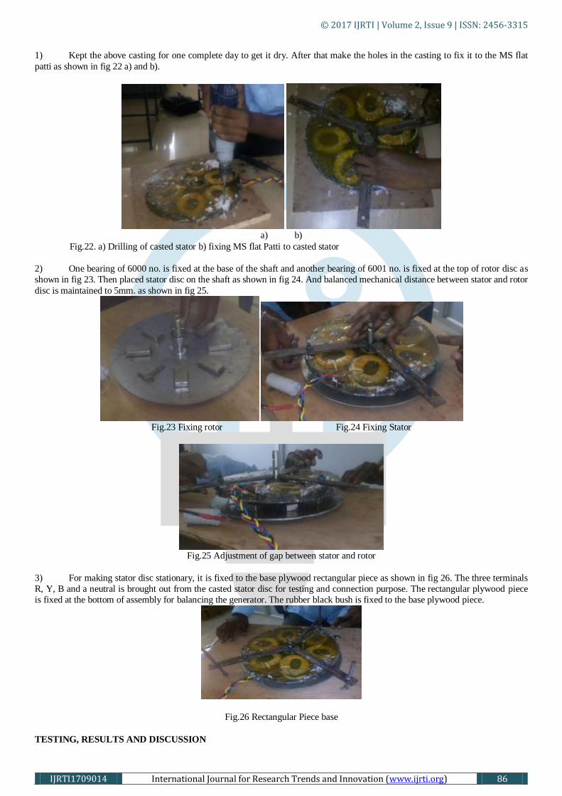
1) Kept the above casting for one complete day to get it dry. After that make the holes in the casting to fix it to the MS flat
patti as shown in fig 22 a) and b).
a) b)
Fig.22. a) Drilling of casted stator b) fixing MS flat Patti to casted stator
2) One bearing of 6000 no. is fixed at the base of the shaft and another bearing of 6001 no. is fixed at the top of rotor disc as
shown in fig 23. Then placed stator disc on the shaft as shown in fig 24. And balanced mechanical distance between stator and rotor
disc is maintained to 5mm. as shown in fig 25.
Fig.23 Fixing rotor Fig.24 Fixing Stator
Fig.25 Adjustment of gap between stator and rotor
3) For making stator disc stationary, it is fixed to the base plywood rectangular piece as shown in fig 26. The three terminals
R, Y, B and a neutral is brought out from the casted stator disc for testing and connection purpose. The rectangular plywood piece
is fixed at the bottom of assembly for balancing the generator. The rubber black bush is fixed to the base plywood piece.
Fig.26 Rectangular Piece base
TESTING, RESULTS AND DISCUSSION

© 2017 IJRTI | Volume 2, Issue 9 | ISSN: 2456-3315
IJRTI1709014 International Journal for Research Trends and Innovation (www.ijrti.org) 87
I. TESTING
Once the fabrication of AFPM Generator is finished, its testing is done in the college machine laboratory. Since it is not possible at
student level to place a wind turbine for testing purpose hence the testing is done in college laboratory. So instead of using wind
turbine to give mechanical input to generator , a prime mover having high torque and low speed is selected to give input to the
generator. Such a prime mover is our drill machine which generally has high torque and low speed as per our requirement.
Following Two tests are conducted on generator to check its performance:
A) No- load Test:
In this test generator is acting as open circuit i.e. load is not connected to its output as shown in fig 27. With the help of drill
machine input is given to the generator. Different input speeds are given to generator for checking its no load performance.
Fig.27. No load test on generator
The drill machine is connected through dimmer to the supply voltage to achieve different speeds. The phase and line voltages are
measured for different input speed of prime mover as shown in table 5 below.
Table 5) No load test readings
Sr. No Speed(N)
(rpm)
Output Voltage/ph Output Voltage/line
Vrn(V) Vyn(V) Vbn(V) Vry(V) Vyb(V) Vbr(V)
1 75 0.9 0.8 0.8 1 1.1 1.2
2 200 1.7 1.5 1.5 2.5 2.6 2.7
3 300 2.1 1.9 1.9 3.4 3.5 3.8
4 400 2.6 2.5 2.5 4 4.1 4.4
5 550 3.5 3.4 3.4 5.3 5.5 5.9
6 700 4.3 4.2 4.2 6.2 6.4 6.7
7 780 4.9 4.6 4.6 7.1 7.2 7.5
B) Load Test:
In this test the load is connected at the output of the generator. The load requirement is that it should require low voltage and should
consume high current. These types of loads available in the laboratory are rheostats. Hence we taken six rheostats of 5 A and 40Ω
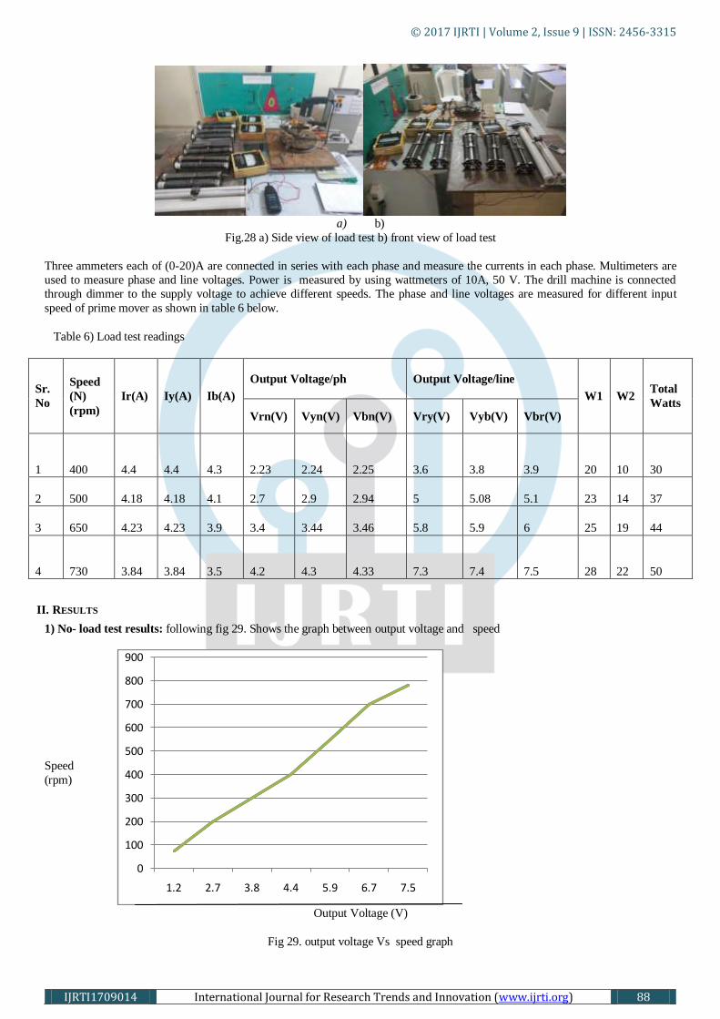
.In each phase two rheostats are connected in parallel to achieve approximately full load on generator as shown in fig 28a) & b).
With the help of drill machine input is given to the generator.
© 2017 IJRTI | Volume 2, Issue 9 | ISSN: 2456-3315
IJRTI1709014 International Journal for Research Trends and Innovation (www.ijrti.org) 88
a) b)
Fig.28 a) Side view of load test b) front view of load test
Three ammeters each of (0-20)A are connected in series with each phase and measure the currents in each phase. Multimeters are
used to measure phase and line voltages. Power is measured by using wattmeters of 10A, 50 V. The drill machine is connected
through dimmer to the supply voltage to achieve different speeds. The phase and line voltages are measured for different input
speed of prime mover as shown in table 6 below.
Table 6) Load test readings
Sr.
No
Speed
(N)
(rpm)
Ir(A) Iy(A) Ib(A)
Output Voltage/ph Output Voltage/line
W1 W2 Total
Watts Vrn(V) Vyn(V) Vbn(V) Vry(V) Vyb(V) Vbr(V)
1
400 4.4 4.4 4.3 2.23 2.24 2.25 3.6 3.8 3.9 20 10
30
2
500 4.18 4.18 4.1 2.7 2.9 2.94 5 5.08 5.1 23 14
37
3
650 4.23 4.23 3.9 3.4 3.44 3.46 5.8 5.9 6 25 19
44
4
730 3.84 3.84 3.5 4.2 4.3 4.33 7.3 7.4 7.5 28 22
50
II. RESULTS
1) No- load test results: following fig 29. Shows the graph between output voltage and speed
Output Voltage (V)
Fig 29. output voltage Vs speed graph
0
100
200
300
400
500
600
700
800
900
1.2 2.7 3.8 4.4 5.9 6.7 7.5
Speed
(rpm)

© 2017 IJRTI | Volume 2, Issue 9 | ISSN: 2456-3315
IJRTI1709014 International Journal for Research Trends and Innovation (www.ijrti.org) 89
2) Load test results :
Following fig. 30 shows the graph between current and speed
Current (A)
Fig. 30. CurrentVs speed
Following fig 31 shows the graph between speed and power
Power (W)
Fig 31. Speed Vs power
I. CONCLUSION
Theoretical design of single stator single rotor AFPM generator is done first with the help of mathematical formulas and then
fabricates the generator in the college machine laboratory and workshop with help of electrical and mechanical tools Finally run the
generator by prime move at the calculated wind speed in the college laboratory. Conduct two test on generator namely no load test
and load test .Draw the observation table and take the readings. After that draw the graph and observe the results.
This project introduced an alternative design procedure for PM generators, Which selects an optimized permutation of design
variables based on maximizing theenergy yield from the machine.This is indirect contrast to classical design methodology.The
practical results obtained by our project are not exactly match perfectly with our theoratical calculations or design.This mismatch is
due to the following reasons:
1) Due to increase inair gap between rotor and stator because of bad handling.
2) Due to imperfection in cutting of circular plates.
3) Due to improper pouring of resin, there is no uniform distribution of resin.
II. FUTURE SCOPE
With certain changesthis type of generator can be used for electrical energy generation on large scale.The changes are like:
1) More development in mechanical design .
2) Use of more pure and efficient epoxy resin.
3) Addition of one motor rotor magnet disc.
4) Use of trapezoidal shaped magnets
0
100
200
300
400
500
600
700
800
4.4 4.18 4.23 3.84
0
100
200
300
400
500
600
700
800
30 37 44 50
Speed (rpm)
Speed (rpm)

© 2017 IJRTI | Volume 2, Issue 9 | ISSN: 2456-3315
IJRTI1709014 International Journal for Research Trends and Innovation (www.ijrti.org) 90
REFERENCES
[1] M. Aydin, Member, IEEE, M. K. Guven, Member, IEEE, “Design of Several Permanent Magnet Synchronous Generators
for High Power Traction Applications” Electrical machines and drives conference (IDMDC).2013 IEEE international conference.
[2] K.C. Latoufis1, G.M. Messinis1, P.C. Kotsampopoulos1 and N.D. Hatziargyriou1” Axial Flux Permanent Magnet
Generator Design for Low Cost Manufacturing of Small Wind Turbines”, wind engineering volume 36, no. 4, 2012 pp 411-442
411.
[3] Samuel O. Ani, HenkPolinder and Jan. A. Ferreira, “Low Cost Axial Flux PM Generator for Small Wind
Turbines”,Electrical Power Processing, Delft University of Technology Mekelweg 4, 2628 CD Delft, Netherlands.2012 IEEE
[4] A.Mahmoudi*, N.A.Rahim and W.P. Hew “Axial flux permanent magnet machine modeling,design,simulation and
analysis ”,Scientific Research and Essays Vol. 6(12), pp. 2525-2549, 18 June, 2011
[5] B.Xia,M.J.Jin ,J.X.Shen and A.G.Zhang,”Design and analysis of an air cored axial flux permanent magnet generator for
small wind power application”,IEEE ICSET 2010,kandy,Sri Lanka
[6] T. F. Chan, L. L. Lai and ShumingXie. “Field Computation for an Axial Flux Permanent-Magnet Synchronous
Generator”, IEEETRANSACTIONS ON ENERGY CONVERSION, vol. 24 No.1, pp. 1-11,March 2009.
[7] A. P. Ferreira1 and A. F. Costa,”Direct Driven Axial Flux Permanent Magnet Generator for Small-Scale Wind Power
Applications”, International Conference on Renewable Energies and Power Quality (ICREPQ’11),Las Palmas de Gran Canaria
(Spain), 13th to 15th April, 2010
[8] A.DiGerlando, G. Foglia, M.F. Iacchetti, R. Perini,”Design criteria of axial flux PM Machines for direct drive wind
energy generation” ,XIX International Conference on Electrical Machines,ICEM 2010,Rome,© 2010 IEEE.
[9] Hugh Piggott, “The Axial flux wind mill plans,A wind turbine recipe book.”, January 2009-metric edition
[10] Garrison F. Price, Todd D. Batzel, MihaiComanescu, and Bruce A. Muller, “Design and Testing of a Permanent Magnet
Axial Flux Wind Power Generator”, Proceedings of The 2008 IAJC-IJME International Conference ISBN 978-1-60643-379-9.
[11] J.R. Bumby,N. Stannard, J Dominy and N. McLeod, “A Permanent magnet generator for small scale wind and water
turbines”, proceedings of the 2008 international conference on electrical machines,©2008 IEEE
[12] A. Mahmoudi*, N. A. Rahim and W. P. Hew, “Axial-flux permanent-magnet machine modeling, design, simulation and
analysis” Scientific Research and Essays Vol. 6(12), pp. 2525-2549, 18 June, 2011
[13] Hendrik Vansompel, Peter Sergeant and Luc Dupré, “Optimized Design Considering the Mass Influence of an Axial Flux
Permanent-Magnet Synchronous Generator with Concentrated Pole Windings, IEEE TRANSACTIONS ON MAGNETICS, VOL.
46, NO. 12, DECEMBER 2010”
[14] Rong-Jie Wang, Maarten J. Kamper, Kobus Van der Westhuizen, “Optimal Design of a Coreless Stator Axial Flux
Permanent-Magnet Generator” IEEE transactions on magnetics, vol. 41, no. 1, january 2005