Design and Analisys of Heavy Vehicle Chassis by Using ... · Design and Analisys of Heavy Vehicle...
10
Page 1418 Design and Analisys of Heavy Vehicle Chassis by Using Composite Materials K. Venkatarao M-Tech (CAD/CAM) Mechanical Engineering Department Malla Reddy College Of Engineering J. Chandra Sekhar Assistant Professor Mechanical Engineering Department Malla Reddy College Of Engineering ABSTRACT The automobile is divided into two parts body and chassis. The chassis is basic structure of a vehicle. It contains all the engine parts and power systems but the frame is the main portion of chassis which do not contain any other assemblies like engine parts. Its principle function is to safely carry the maximum load for all designed operating conditions. Composite material is a material composed of two or more distinct phases (matrix phase and dispersed phase) and having bulk properties significantly different from those of any of the constituents. Different types of composite material are available and one of it is Polymer matrix composite. It is very popular due to their low cost and simple fabrication methods. It has the benefits of high tensile strength, high stiffness and good corrosion resistance etc. At present this polymer matrix composite materials are used in aerospace, automobile industries due to it high strength to low weight ratio. In the present work, the dimensions of an existing heavy vehicle chassis of a TATA 1109 EX2 vehicle is taken for modeling and analysis. The vehicle frame is initially modeled by considering ‘C’ cross section in CATIA V5 SOFTWARE and then it is imported to ANSYS 13.0. The analysis is done with two different composite materials namely E- glass/Epoxy and S-glass/Epoxy subjected to the same pressure as that of a steel frame. The design constraints are stresses and deformations. The results are then compared to finalize the best among all the four frames. Key Words: CATIA V5 R20, ANSYS 13.0. I. INTRODUCTION Automotive chassis is a French word that was initially used to represent the basic structure. It is a skeletal frame on which various mechanical parts like engine, tires, axle assemblies, brakes, steering etc. are bolted. It gives strength and stability to the vehicle under different conditions. At the time of manufacturing, the body of a vehicle is flexibly molded according to the structure of chassis. Automobile chassis is usually made of light sheet metal or composite plastics. It provides strength needed for supporting vehicular components and payload placed upon it. Automotive chassis or automobile chassis helps keep an automobile rigid, stiff and unbending. It ensures low levels of noise, vibrations and harshness throughout the automobile. Automobile chassis without the wheels and other engine parts is called frame. Automobile frames provide strength and flexibility to the automobile. The backbone of any automobile, it is the supporting frame to which the body of an engine, axle assemblies are affixed. Tie bars that are essential parts of automotive frames are fasteners that bind different auto parts together. Automotive frames are basically manufactured from steel. Aluminum is another raw material that has increasingly become popular for manufacturing these auto frames. In an automobile, front frame is a set of metal parts that forms the framework which also supports the front wheels. Automotive frames are basically manufactured from steel. Aluminum is another raw material that has increasingly become popular for manufacturing these auto frames. In an automobile, front frame is a set of metal parts that forms the framework which also supports the front wheels. It provides strength needed
Transcript of Design and Analisys of Heavy Vehicle Chassis by Using ... · Design and Analisys of Heavy Vehicle...
Page 1418
Design and Analisys of Heavy Vehicle Chassis by Using Composite
Materials K. Venkatarao
M-Tech (CAD/CAM)
Mechanical Engineering Department
Malla Reddy College Of Engineering
J. Chandra Sekhar
Assistant Professor
Mechanical Engineering Department
Malla Reddy College Of Engineering
ABSTRACT
The automobile is divided into two parts body and
chassis. The chassis is basic structure of a vehicle. It
contains all the engine parts and power systems but
the frame is the main portion of chassis which do
not contain any other assemblies like engine parts.
Its principle function is to safely carry the
maximum load for all designed operating
conditions. Composite material is a material
composed of two or more distinct phases (matrix
phase and dispersed phase) and having bulk
properties significantly different from those of any
of the constituents. Different types of composite
material are available and one of it is Polymer
matrix composite. It is very popular due to their
low cost and simple fabrication methods. It has the
benefits of high tensile strength, high stiffness and
good corrosion resistance etc. At present this
polymer matrix composite materials are used in
aerospace, automobile industries due to it high
strength to low weight ratio.
In the present work, the dimensions of an existing
heavy vehicle chassis of a TATA 1109 EX2 vehicle
is taken for modeling and analysis. The vehicle
frame is initially modeled by considering ‘C’ cross
section in CATIA V5 SOFTWARE and then it is
imported to ANSYS 13.0. The analysis is done with
two different composite materials namely E-
glass/Epoxy and S-glass/Epoxy subjected to the
same pressure as that of a steel frame. The design
constraints are stresses and deformations. The
results are then compared to finalize the best
among all the four frames.
Key Words: CATIA V5 R20, ANSYS 13.0.
I. INTRODUCTION
Automotive chassis is a French word that was initially
used to represent the basic structure. It is a skeletal
frame on which various mechanical parts like engine,
tires, axle assemblies, brakes, steering etc. are bolted.
It gives strength and stability to the vehicle under
different conditions. At the time of manufacturing, the
body of a vehicle is flexibly molded according to the
structure of chassis. Automobile chassis is usually
made of light sheet metal or composite plastics. It
provides strength needed for supporting vehicular
components and payload placed upon it. Automotive
chassis or automobile chassis helps keep an
automobile rigid, stiff and unbending. It ensures low
levels of noise, vibrations and harshness throughout
the automobile.
Automobile chassis without the wheels and other
engine parts is called frame. Automobile frames
provide strength and flexibility to the automobile. The
backbone of any automobile, it is the supporting frame
to which the body of an engine, axle assemblies are
affixed. Tie bars that are essential parts of automotive
frames are fasteners that bind different auto parts
together. Automotive frames are basically
manufactured from steel. Aluminum is another raw
material that has increasingly become popular for
manufacturing these auto frames. In an automobile,
front frame is a set of metal parts that forms the
framework which also supports the front wheels.
Automotive frames are basically manufactured from
steel. Aluminum is another raw material that has
increasingly become popular for manufacturing these
auto frames. In an automobile, front frame is a set of
metal parts that forms the framework which also
supports the front wheels. It provides strength needed
Page 1419
for supporting vehicular components and payload
placed upon it.
1.1 Functions of the chassis
1. To carry load of the passengers or goods
carried in the body.
2. To support the load of the body, engine, gear
box etc.,
3. To with stand the forces caused due to the
sudden braking or acceleration.
4. To with stand the stresses caused due to the bad
road condition.
5. To with stand centrifugal force while cornering.
1.2 Various loads acting on the chassis
1. Short duration Load – While crossing a broken
patch.
2. Momentary duration Load – While taking a
curve.
3. Impact Loads – Due to the collision of the
vehicle.
4. Inertia Load – While applying brakes.
5. Static Loads – Loads due to chassis parts.
6. Over Loads – Beyond Design capacity.
2. Problem Identification
Weight reduction is now the main issue in automobile
industries. Because if the weight of the vehicle
increases the fuel consumption increases. At the same
time as the weight of the vehicle increases the cost also
increases which becomes a major issue while
purchasing an automobile. For example if we take
frame of TATA 1109 EX 2 heavy vehicle frame. It is
manufactured with Structural Steel. Steel structures
exposed to air and water, such as bridges are
susceptible to corrosion. In conditions of repeated
stress and more temperatures it can suffer fatigue and
cracks. These are the main problems of steel and these
are compensated by inducing composite materials.
2.1Composite Materials
A composite material is defined as a material
composed of two or more materials combined on a
macroscopic scale by mechanical and chemical bonds.
Unique characteristic of many fiber reinforced
composites is their high internal damping capacity.
This leads to better vibration energy absorption within
the material and results in reduced noise transmission
to neighboring structures. Many composite materials
offer a combination of strength and modulus that are
either comparable to or better than any traditional
metallic metals. Because of their low specific gravities,
the strength to weight-ratio and modulus to weight-
ratios of these composite materials are markedly
superior to those of metallic materials. The fatigue
strength to weight ratios as well as fatigue damage
tolerances of many composite laminates are excellent.
For these reasons, fiber composites have emerged as a
major class of structural material and are either used or
being considered as substitutions for metals in many
weight-critical components in aerospace, automotive
and other industries.
2.2 Classification of FRP:
A great majority of materials are stronger and stiffer in
fibrous form than as bulk materials. A high fiber
aspect ratio (length: diameter ratio) permits very
effective transfer of load via matrix materials to the
fibers, thus taking advantage of their excellent
properties. Therefore, fibers are very effective and
attractive reinforcement materials.
2.2.1 Glass Fibers:
The most common reinforcement for the polymer
matrix composites is a glass fiber. Most of the fibers
are based on silica (SiO2), with addition of oxides of
Ca, B, Na, Fe, and Al. The glass fibers are divided into
three classes’ ‐‐ E‐glass, S‐glass and C‐glass. The
E‐glass is designated for electrical use and the S‐glass
for high strength. The C‐glass is for high corrosion
resistance, and it is uncommon for civil engineering
application. Of the three fibers, the E‐glass is the most
common reinforcement material used in civil
structures. It is produced from lime‐alumina
borosilicate which can be easily obtained from
abundance of raw materials like sand. The glass fiber
strength and modulus can degrade with increasing
Page 1420
temperature. Although the glass material creeps under
a sustained load, it can be designed to perform
satisfactorily. The fiber itself is regarded as an
isotropic material and has a lower thermal expansion
coefficient than that of steel.
• E-glass:
Family of glassed with a calcium aluminum
borosilicate composition and a maximum alkali
composition of 2%. These are used when strength and
high electrical resistivity are required.
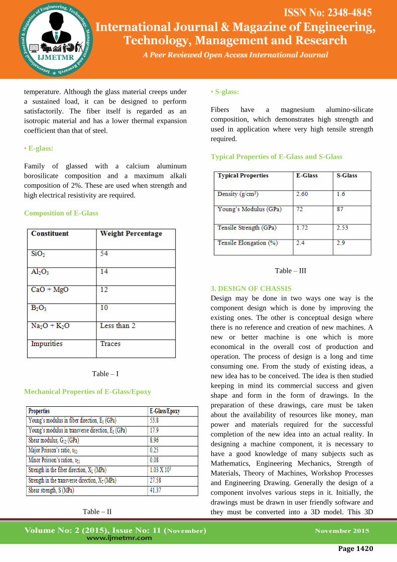
Composition of E-Glass
Table – I
Mechanical Properties of E-Glass/Epoxy
Table – II
• S-glass:
Fibers have a magnesium alumino‐silicate
composition, which demonstrates high strength and
used in application where very high tensile strength
required.
Typical Properties of E-Glass and S-Glass
Table – III
3. DESIGN OF CHASSIS
Design may be done in two ways one way is the
component design which is done by improving the
existing ones. The other is conceptual design where
there is no reference and creation of new machines. A
new or better machine is one which is more
economical in the overall cost of production and
operation. The process of design is a long and time
consuming one. From the study of existing ideas, a
new idea has to be conceived. The idea is then studied
keeping in mind its commercial success and given
shape and form in the form of drawings. In the
preparation of these drawings, care must be taken
about the availability of resources like money, man
power and materials required for the successful
completion of the new idea into an actual reality. In
designing a machine component, it is necessary to
have a good knowledge of many subjects such as
Mathematics, Engineering Mechanics, Strength of
Materials, Theory of Machines, Workshop Processes
and Engineering Drawing. Generally the design of a
component involves various steps in it. Initially, the
drawings must be drawn in user friendly software and
they must be converted into a 3D model. This 3D
Page 1421
model must be imported into an analyzing medium
where it is structurally or thermally analyzed to sustain
the need.
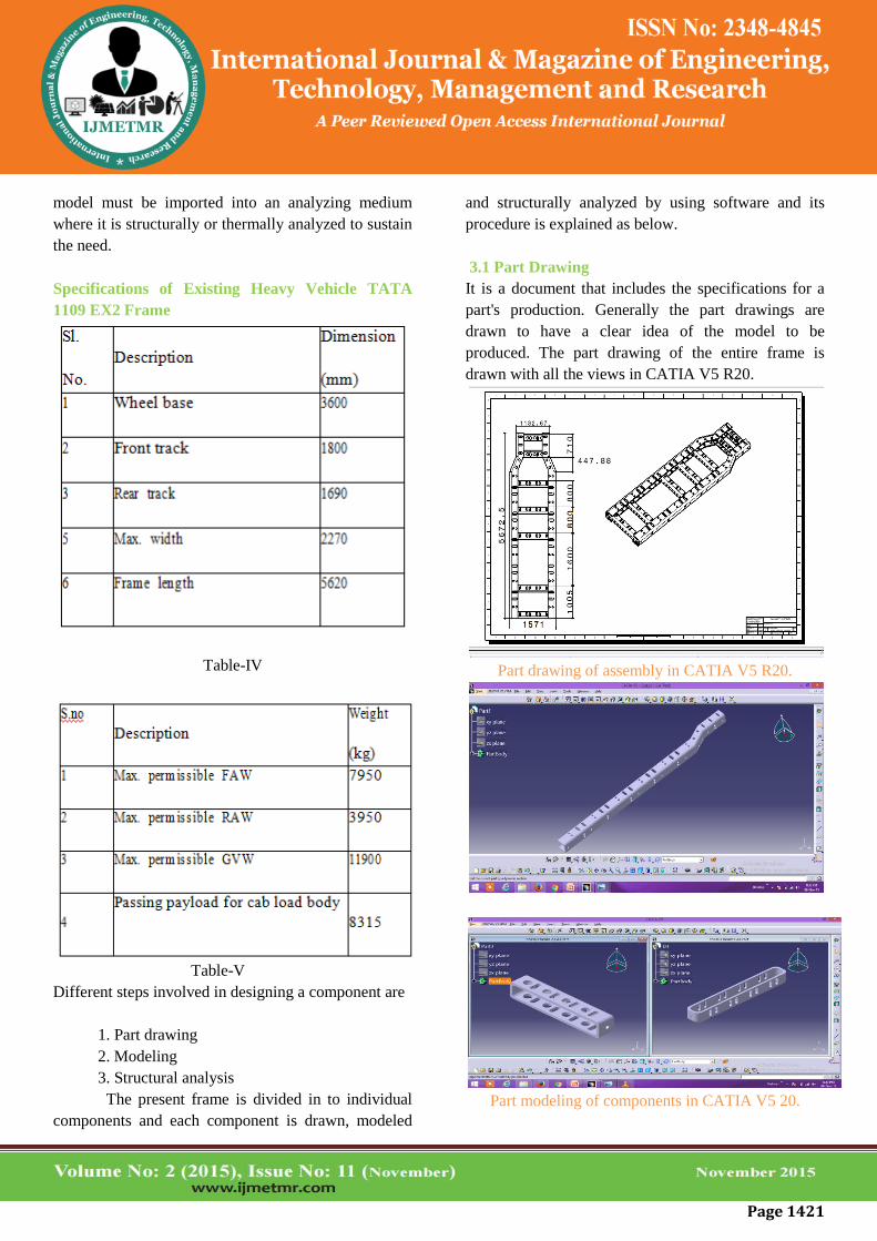
Specifications of Existing Heavy Vehicle TATA
1109 EX2 Frame
Table-IV
Table-V
Different steps involved in designing a component are
1. Part drawing
2. Modeling
3. Structural analysis
The present frame is divided in to individual
components and each component is drawn, modeled
and structurally analyzed by using software and its
procedure is explained as below.
3.1 Part Drawing
It is a document that includes the specifications for a
part's production. Generally the part drawings are
drawn to have a clear idea of the model to be
produced. The part drawing of the entire frame is
drawn with all the views in CATIA V5 R20.
Part drawing of assembly in CATIA V5 R20.
Part modeling of components in CATIA V5 20.
Page 1422
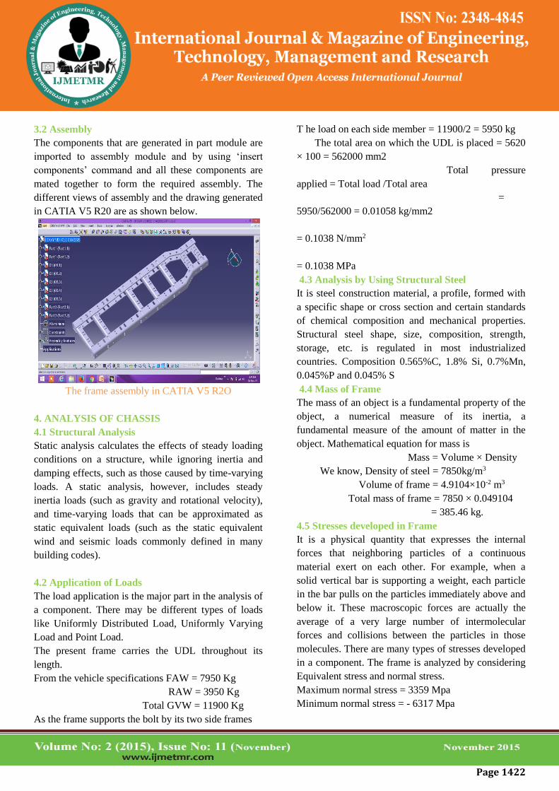
3.2 Assembly
The components that are generated in part module are
imported to assembly module and by using ‘insert
components’ command and all these components are
mated together to form the required assembly. The
different views of assembly and the drawing generated
in CATIA V5 R20 are as shown below.
The frame assembly in CATIA V5 R2O
4. ANALYSIS OF CHASSIS
4.1 Structural Analysis
Static analysis calculates the effects of steady loading
conditions on a structure, while ignoring inertia and
damping effects, such as those caused by time-varying
loads. A static analysis, however, includes steady
inertia loads (such as gravity and rotational velocity),
and time-varying loads that can be approximated as
static equivalent loads (such as the static equivalent
wind and seismic loads commonly defined in many
building codes).
4.2 Application of Loads
The load application is the major part in the analysis of
a component. There may be different types of loads
like Uniformly Distributed Load, Uniformly Varying
Load and Point Load.
The present frame carries the UDL throughout its
length.
From the vehicle specifications FAW = 7950 Kg
RAW = 3950 Kg
Total GVW = 11900 Kg
As the frame supports the bolt by its two side frames
T he load on each side member = 11900/2 = 5950 kg
The total area on which the UDL is placed = 5620
× 100 = 562000 mm2
Total pressure
applied = Total load /Total area
=
5950/562000 = 0.01058 kg/mm2
= 0.1038 N/mm2
= 0.1038 MPa
4.3 Analysis by Using Structural Steel
It is steel construction material, a profile, formed with
a specific shape or cross section and certain standards
of chemical composition and mechanical properties.
Structural steel shape, size, composition, strength,
storage, etc. is regulated in most industrialized
countries. Composition 0.565%C, 1.8% Si, 0.7%Mn,
0.045%P and 0.045% S
4.4 Mass of Frame
The mass of an object is a fundamental property of the
object, a numerical measure of its inertia, a
fundamental measure of the amount of matter in the
object. Mathematical equation for mass is
Mass = Volume × Density
We know, Density of steel = 7850kg/m3
Volume of frame = 4.9104×10⁻² m3
Total mass of frame = 7850 × 0.049104
= 385.46 kg.
4.5 Stresses developed in Frame
It is a physical quantity that expresses the internal
forces that neighboring particles of a continuous
material exert on each other. For example, when a
solid vertical bar is supporting a weight, each particle
in the bar pulls on the particles immediately above and
below it. These macroscopic forces are actually the
average of a very large number of intermolecular
forces and collisions between the particles in those
molecules. There are many types of stresses developed
in a component. The frame is analyzed by considering
Equivalent stress and normal stress.
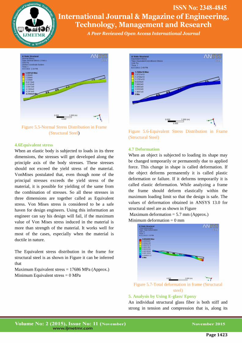
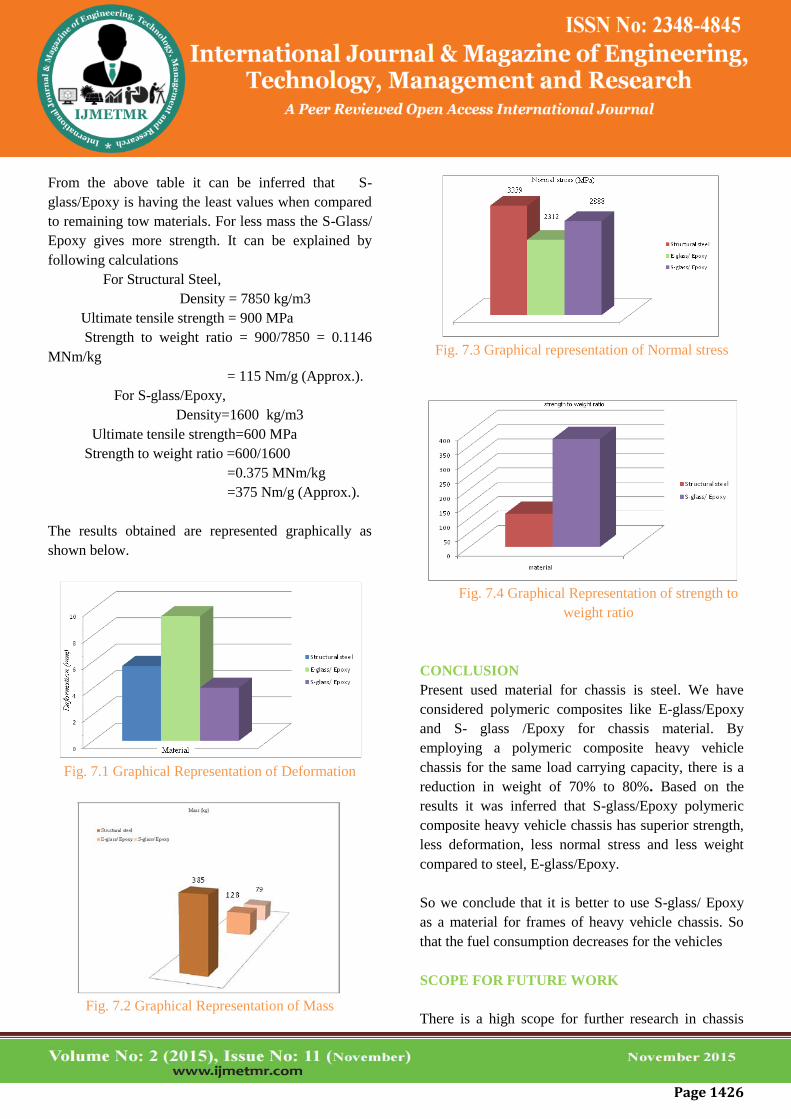
Maximum normal stress = 3359 Mpa
Minimum normal stress = - 6317 Mpa
Page 1423
Figure 5.5-Normal Stress Distribution in Frame
(Structural Steel)
4.6Equivalent stress
When an elastic body is subjected to loads in its three
dimensions, the stresses will get developed along the
principle axis of the body stresses. These stresses
should not exceed the yield stress of the material.
VonMises postulated that, even though none of the
principal stresses exceeds the yield stress of the
material, it is possible for yielding of the same from
the combination of stresses. So all these stresses in
three dimensions are together called as Equivalent
stress. Von Mises stress is considered to be a safe
haven for design engineers. Using this information an
engineer can say his design will fail, if the maximum
value of Von Mises stress induced in the material is
more than strength of the material. It works well for
most of the cases, especially when the material is
ductile in nature.
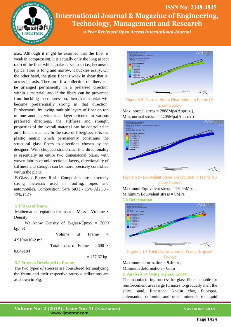
The Equivalent stress distribution in the frame for
structural steel is as shown in Figure it can be inferred
that
Maximum Equivalent stress = 17686 MPa (Approx.)
Minimum Equivalent stress = 0 MPa
Figure 5.6-Equivalent Stress Distribution in Frame
(Structural Steel)
4.7 Deformation
When an object is subjected to loading its shape may
be changed temporarily or permanently due to applied
force. This change in shape is called deformation. If
the object deforms permanently it is called plastic
deformation or failure. If it deforms temporarily it is
called elastic deformation. While analyzing a frame
the frame should deform elastically within the
maximum loading limit so that the design is safe. The
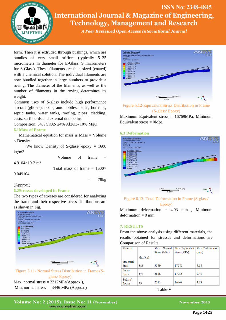
values of deformation obtained in ANSYS 13.0 for
structural steel are as shown in Figure
Maximum deformation = 5.7 mm (Approx.)
Minimum deformation = 0 mm
Figure 5.7-Total deformation in frame (Structural
steel)
5. Analysis by Using E-glass/ Epoxy
An individual structural glass fiber is both stiff and
strong in tension and compression that is, along its
Page 1424
axis. Although it might be assumed that the fiber is
weak in compression, it is actually only the long aspect
ratio of the fiber which makes it seem so i.e., because a
typical fiber is long and narrow, it buckles easily. On
the other hand, the glass fiber is weak in shear that is,
across its axis. Therefore if a collection of fibers can
be arranged permanently in a preferred direction
within a material, and if the fibers can be prevented
from buckling in compression, then that material will
become preferentially strong in that direction.
Furthermore, by laying multiple layers of fiber on top
of one another, with each layer oriented in various
preferred directions, the stiffness and strength
properties of the overall material can be controlled in
an efficient manner. In the case of fiberglass, it is the
plastic matrix which permanently constrains the
structural glass fibers to directions chosen by the
designer. With chopped strand mat, this directionality
is essentially an entire two dimensional plane; with
woven fabrics or unidirectional layers, directionality of
stiffness and strength can be more precisely controlled
within the plane.
E-Glass / Epoxy Resin Composites are extremely
strong materials used in roofing, pipes and
automobiles. Composition: 54% SiO2 - 15% Al2O3 -
12% CaO
5.1 Mass of frame
Mathematical equation for mass is Mass = Volume ×
Density
We know Density of E-glass/Epoxy = 2600
kg/m3
Volume of Frame =
4.9104×10⁻² m³
Total mass of Frame = 2600 ×
0.049104
= 127.67 kg
5.2 Stresses Developed in Frame
The two types of stresses are considered for analyzing
the frame and their respective stress distributions are
as shown in Fig.
Figure 5.8- Normal Stress Distribution in Frame (E-
glass/ Epoxy)
Max. normal stress = 2888Mpa(Approx.),
Min. normal stress = -4205Mpa(Approx.)
Figure 5.9- Equivalent Stress Distribution in Frame (E-
glass/ Epoxy)
Maximum Equivalent stress = 17055Mpa ,
Minimum Equivalent stress = 0MPa
5.3 Deformation
Figure 5.10-Total Deformation in Frame (E-glass/
Epoxy)
Maximum deformation = 9.4mm ,
Minimum deformation = 0mm
6. Analysis by Using S-glass/ Epoxy
The manufacturing process for glass fibers suitable for
reinforcement uses large furnaces to gradually melt the
silica sand, limestone, kaolin clay, fluorspar,
colemanite, dolomite and other minerals to liquid
Page 1425
form. Then it is extruded through bushings, which are
bundles of very small orifices (typically 5–25
micrometers in diameter for E-Glass, 9 micrometers
for S-Glass). These filaments are then sized (coated)
with a chemical solution. The individual filaments are
now bundled together in large numbers to provide a
roving. The diameter of the filaments, as well as the
number of filaments in the roving determines its
weight.
Common uses of S-glass include high performance
aircraft (gliders), boats, automobiles, baths, hot tubs,
septic tanks, water tanks, roofing, pipes, cladding,
casts, surfboards and external door skins.
Composition: 64% SiO2- 24% Al2O3- 10% MgO
6.1Mass of Frame
Mathematical equation for mass is Mass = Volume
× Density
We know Density of S-glass/ epoxy = 1600
kg/m3
Volume of frame =
4.9104×10⁻² m³
Total mass of frame = 1600×
0.049104
= 79kg
(Approx.)
6.2Stresses developed in Frame
The two types of stresses are considered for analyzing
the frame and their respective stress distributions are
as shown in Fig.
Figure 5.11- Normal Stress Distribution in Frame (S-
glass/ Epoxy)
Max. normal stress = 2312MPa(Approx.),
Min. normal stress = -3446 MPa (Approx.)
Figure 5.12-Equivalent Stress Distribution in Frame
(S-glass/ Epoxy)
Maximum Equivalent stress = 16769MPa, Minimum
Equivalent stress = 0Mpa
6.3 Deformation
Figure 6.13- Total Deformation in Frame (S-glass/
Epoxy)
Maximum deformation = 4.03 mm , Minimum
deformation = 0 mm
7. RESULTS
From the above analysis using different materials, the
results obtained for stresses and deformations are
Comparison of Results
Table-V
Page 1426
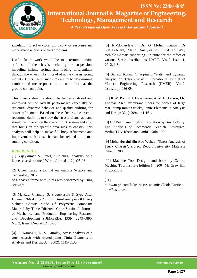
From the above table it can be inferred that S-
glass/Epoxy is having the least values when compared
to remaining tow materials. For less mass the S-Glass/
Epoxy gives more strength. It can be explained by
following calculations
For Structural Steel,
Density = 7850 kg/m3
Ultimate tensile strength = 900 MPa
Strength to weight ratio = 900/7850 = 0.1146
MNm/kg
= 115 Nm/g (Approx.).
For S-glass/Epoxy,
Density=1600 kg/m3
Ultimate tensile strength=600 MPa
Strength to weight ratio =600/1600
=0.375 MNm/kg
=375 Nm/g (Approx.).
The results obtained are represented graphically as
shown below.
Fig. 7.1 Graphical Representation of Deformation
Fig. 7.2 Graphical Representation of Mass
Fig. 7.3 Graphical representation of Normal stress
Fig. 7.4 Graphical Representation of strength to
weight ratio
CONCLUSION
Present used material for chassis is steel. We have
considered polymeric composites like E-glass/Epoxy
and S- glass /Epoxy for chassis material. By
employing a polymeric composite heavy vehicle
chassis for the same load carrying capacity, there is a
reduction in weight of 70% to 80%. Based on the
results it was inferred that S-glass/Epoxy polymeric
composite heavy vehicle chassis has superior strength,
less deformation, less normal stress and less weight
compared to steel, E-glass/Epoxy.
So we conclude that it is better to use S-glass/ Epoxy
as a material for frames of heavy vehicle chassis. So
that the fuel consumption decreases for the vehicles
SCOPE FOR FUTURE WORK
There is a high scope for further research in chassis
Page 1427
simulation to solve vibration, frequency response and
mode shape analysis related problems.
Useful future work would be to determine torsion
stiffness of the chassis including the suspension,
modeling infinite springs and loading differentially
through the wheel hubs instead of at the chassis spring
mounts. Other useful measures are to be determining
camber and toe response to a lateral force at the
ground contact point.
This chassis structure should be further analyzed and
improved on the overall performance especially on
structural dynamic behavior and quality auditing for
better refinement. Based on these factors, the overall
recommendation is to study the structural analysis and
should be covered on the overall truck system and after
that focus on the specific area such as chassis. This
analysis will help to make full body refinement and
improvement because it can be related to actual
running condition.
REFERENCES
[1] Vijaykumar V. Patel, "Structural analysis of a
ladder chassis frame," World Journal of 2(4)05-08
[2] Cicek Karao a journal on analysis Science and
Technology 2012,
of a chassis frame with joints was performed by using
software
[3] M. Ravi Chandra, S. Sreenivasulu & Syed Altaf
Hussain, "Modeling And Structural Analysis Of Heavy
Vehicle Chassis Made Of Polymeric Composite
Material By Three Different Cross Sections", Journal
of Mechanical and Production Engineering Research
and Development (IJMPERD), ISSN 2249-6890,
Vol.2, Issue 2,Sep 2012 45-60.
[4] C. Karaoglu, N. S. Kuralay, Stress analysis of a
truck chassis with riveted joints, Finite Elements in
Analysis and Design, 38, (2002), 1115-1130.
[5] N.V.Dhandapani, Dr. G Mohan Kumar, Dr
K.K.Debnath, Static Analysis of Off-High Way
Vehicle Chassis supporting Structure for the effect of
various Stress distributions IJART, Vol.2 Issue 1,
2012, 1-8.
[6] Sairam Kotari, V.Gopinath,"Static and dynamic
analysis on Tatra chassis" International Journal of
Modern Engineering Research (IJMER), Vol.2,
Issue.1, pp-086-094.
[7] K.W. Poh, P.H. Dayawansa, A.W. Dickerson, I.R.
Thomas, Steel membrane floors for bodies of large
rear- dump mining trucks, Finite Elements in Analysis
and Design 32, (1999), 141-161.
[8] H J Beermann, English translation by Guy Tidbury,
The Analysis of Commercial Vehicle Structures,
Verlag TUV Rheinland GmbH Koln-1989.
[9] Mohd Husaini Bin Abd Wahab, "Stress Analysis of
Truck Chassis", Project Report University Malaysia
Pahang, 2009
[10] Machine Tool Design hand book by Central
Machine Tool Institute Edition 1 – 2004 Mc Graw Hill
Publications
[11]
http://ansys.com/Industries/Academics/Tools/Curricul
um+Resources