Design, Analysis and Validation of Conceptual Bricks ...in linear static equivalent lateral loads....
12
IJIRST –International Journal for Innovative Research in Science & Technology| Volume 3 | Issue 02 | July 2016 ISSN (online): 2349-6010 All rights reserved by www.ijirst.org 192 Design, Analysis and Validation of Conceptual Bricks Handling Trailer Vinod Hiwase Prof. R. R. Gandhe M. Tech. Student Assistant Professor Department of Mechanical Engineering Department of Mechanical Engineering AGPCE, Nagpur, Maharashtra, India AGPCE, Nagpur, Maharashtra, India Abstract Nowadays, construction industry is on a boom. Almost everywhere one can find some kind of construction work in progress. At every construction site bricks are required. For normal wall construction bricks are must have. Bricks are of vital importance in construction. To provide bricks in time at the construction site and that too without damage is still a challenge in India. But manually handling these bricks cause workers to suffer from back injury and long-term pain if regularly lifting/carrying heavy or awkward objects. So, the palletizing and mechanization of the bricks is suggested so as to reduce the human injury and to increase the productivity and profitability. Keywords: Bricks, Construction Site, Palletizing, Mechanization _______________________________________________________________________________________________________ I. INTRODUCTION Expressed in simple language, materials handling is loading, moving and unloading of materials, i.e. raw material, semi/finished good, etc. To do it safely and economically, different types of tackles, gadgets and equipment are used, for mechanical handling of materials. Since primitive times men discovered the use of wheels and levers, they have been moving materials mechanically. Any human activity involving materials need materials handling. However, in the field of engineering and technology, the term materials handling is used with reference to industrial activity. In any industry, be it big or small, involving manufacturing or construction type work, materials have to be handled as raw materials, intermediate goods or finished products from the point of receipt and storage of raw materials, through production processes and up to finished goods storage and dispatch points. A material handling as such is not a production process and hence does not add to the value of the product. It also costs money; therefore it should be eliminated or at least reduced as much as possible. However, the important point in favor of materials handling is that it helps production. Depending on the weight, volume and through put of materials, mechanical handling of materials may become unavoidable. In many cases, mechanical handling reduces the cost of manual handling of materials, where such materials handling are highly desirable. All these facts indicate that the type and extent of use of materials handling should be carefully designed to suit the application and which becomes cost effective. Overhead cranes are commonly employed in the transport industry for the loading and unloading of freight, in the construction industry for the movement of materials and in the manufacturing industry for the assembling of heavy equipment, because they can move loads far beyond the normal capability of a human. Thus in this project a detailed design and analysis of the overhead hoist system is undertaken to handle construction bricks. II. LITERATURE REVIEW A.D.Anjikar [1] Handling of raw material, semi-finished, finished product & other material is ever concern & cost in an industry. With increasing cost of labour & its scare city the manual work or operation in industries are now replaced by semi-automatic or automatic system. These low cost systems are not only cost efficient but also enhance productivity & address the issues related to labour problem. Conventionally in micro or small scale industries which are labour intrinsic transportation of raw material, semi finished product is always an expensive & problematic issue. After visiting Waghmare food products, Nagpur & after discussion with the concern the shifting of raw material from store to the work place was a costly labour activity. Presently it is done manually. The industry was interested to identifying some optional material handling system to encounter their problems After carefully survey of factory layout, discussing with management, concern exhaustively literature search it was preferred to design & develop a overhead monorail for handling of raw material The main aims to design cost efficient, overhead monorail material handling system. The detailed drawings will also drawn using the software’s like CATIA/ PRO-E. The cost estimation along with economical feasibility and pay back will also be calculated. Du-Ming Tsai [2] Material handling pallets are the most common tool used in warehousing industries. Nearly every warehouse uses them to some extent. Pallets have become an almost universal warehouse operations tool. They provide a convenient, simple way to transport, stack, and store materials. Traditional palletizing methods load only boxes of the same size on one pallet. For retail business such as grocery distribution or manufacturers that produce many products of small quantities, a wide product mix of different box sizes must be loaded onto the same pallet. The traditional palletizing method may not optimize
Transcript of Design, Analysis and Validation of Conceptual Bricks ...in linear static equivalent lateral loads....
IJIRST –International Journal for Innovative Research in Science & Technology| Volume 3 | Issue 02 | July 2016 ISSN (online): 2349-6010
All rights reserved by www.ijirst.org 192
Design, Analysis and Validation of Conceptual
Bricks Handling Trailer
Vinod Hiwase Prof. R. R. Gandhe
M. Tech. Student Assistant Professor
Department of Mechanical Engineering Department of Mechanical Engineering
AGPCE, Nagpur, Maharashtra, India AGPCE, Nagpur, Maharashtra, India
Abstract
Nowadays, construction industry is on a boom. Almost everywhere one can find some kind of construction work in progress. At
every construction site bricks are required. For normal wall construction bricks are must have. Bricks are of vital importance in
construction. To provide bricks in time at the construction site and that too without damage is still a challenge in India. But
manually handling these bricks cause workers to suffer from back injury and long-term pain if regularly lifting/carrying heavy or
awkward objects. So, the palletizing and mechanization of the bricks is suggested so as to reduce the human injury and to
increase the productivity and profitability.
Keywords: Bricks, Construction Site, Palletizing, Mechanization
_______________________________________________________________________________________________________
I. INTRODUCTION
Expressed in simple language, materials handling is loading, moving and unloading of materials, i.e. raw material, semi/finished
good, etc. To do it safely and economically, different types of tackles, gadgets and equipment are used, for mechanical handling
of materials. Since primitive times men discovered the use of wheels and levers, they have been moving materials mechanically.
Any human activity involving materials need materials handling. However, in the field of engineering and technology, the term
materials handling is used with reference to industrial activity. In any industry, be it big or small, involving manufacturing or
construction type work, materials have to be handled as raw materials, intermediate goods or finished products from the point of
receipt and storage of raw materials, through production processes and up to finished goods storage and dispatch points. A
material handling as such is not a production process and hence does not add to the value of the product. It also costs money;
therefore it should be eliminated or at least reduced as much as possible. However, the important point in favor of materials
handling is that it helps production. Depending on the weight, volume and through put of materials, mechanical handling of
materials may become unavoidable. In many cases, mechanical handling reduces the cost of manual handling of materials, where
such materials handling are highly desirable. All these facts indicate that the type and extent of use of materials handling should
be carefully designed to suit the application and which becomes cost effective.
Overhead cranes are commonly employed in the transport industry for the loading and unloading of freight, in the construction
industry for the movement of materials and in the manufacturing industry for the assembling of heavy equipment, because they
can move loads far beyond the normal capability of a human. Thus in this project a detailed design and analysis of the overhead
hoist system is undertaken to handle construction bricks.
II. LITERATURE REVIEW
A.D.Anjikar [1] Handling of raw material, semi-finished, finished product & other material is ever concern & cost in an industry.
With increasing cost of labour & its scare city the manual work or operation in industries are now replaced by semi-automatic or
automatic system. These low cost systems are not only cost efficient but also enhance productivity & address the issues related to
labour problem. Conventionally in micro or small scale industries which are labour intrinsic transportation of raw material, semi
finished product is always an expensive & problematic issue. After visiting Waghmare food products, Nagpur & after discussion
with the concern the shifting of raw material from store to the work place was a costly labour activity. Presently it is done
manually. The industry was interested to identifying some optional material handling system to encounter their problems After
carefully survey of factory layout, discussing with management, concern exhaustively literature search it was preferred to design
& develop a overhead monorail for handling of raw material The main aims to design cost efficient, overhead monorail material
handling system. The detailed drawings will also drawn using the software’s like CATIA/ PRO-E. The cost estimation along
with economical feasibility and pay back will also be calculated.
Du-Ming Tsai [2] Material handling pallets are the most common tool used in warehousing industries. Nearly every
warehouse uses them to some extent. Pallets have become an almost universal warehouse operations tool. They provide a
convenient, simple way to transport, stack, and store materials. Traditional palletizing methods load only boxes of the same size
on one pallet. For retail business such as grocery distribution or manufacturers that produce many products of small quantities, a
wide product mix of different box sizes must be loaded onto the same pallet. The traditional palletizing method may not optimize
Design, Analysis and Validation of Conceptual Bricks Handling Trailer (IJIRST/ Volume 3 / Issue 02/ 035)
All rights reserved by www.ijirst.org 193
the utilization of the pallet cube. Manual palletizing is an extremely tedious and fatiguing task. Automatic palletization is,
therefore, a potentially attractive alternative. Commercially available palletizers handle only one box size at a time. They cannot
meet the requirements of palletizing applications with mixed box sizes. Industrial robots have always been a viable solution to
complex loading operations due to their flexibility and programming capability.
Sourabh R. Dinde, Rajashekhar S. Talikoti [3] According to the structural point of view Industrial Pallet rack structure can be
considered typical steel framed structure. This work presents a general analysis of an industrial pallet rack structure, evaluating
the influence of each of the components on the global stability. An analytical study for the sensitivity of pallet rack configuration
in linear static equivalent lateral loads. The aim is to braced/unbraced frames were design and their analytical models are to be
built in software. The finite element analysis is used to determine axial forces in beam and column, maximum storey
displacement and buckling loads on braced/unbraced pallet rack structure. Bracing systems are mostly provided to enhance the
stiffness factor of the structures with the seismic loads. Unbraced systems have mostly translational modes of failure and are very
flexible due to excessive loads.
III. IDENTIFIED GAPS IN LITERATURE
Bricks are of vital importance in construction. To provide bricks in time at the construction site and that too without damage is
still a challenge in India. But manually handling these bricks cause workers to suffer from back injury and long-term pain if
regularly lifting/carrying heavy or awkward objects. So, the palletizing and mechanization of the bricks is suggested so as to
reduce the human injury and to increase the productivity and profitability. After closely monitoring the brick handling process
for a Heavy commercial vehicle, following problem were identified,
Labor Force is More
In current material handling system the number of labor required for carrying material from intake zone to delivery zone is more.
Cost is More
Due to large labor force the cost of material handling is increases.
Efficiency is Less
The input provided to the system in terms of labor effort is more but output obtained in terms of material delivered to the
unloading zone is less.
Flexibility in System is Less
There is no other option than the manual conveying system for conveying material which makes the system less flexible to suit
changing atmosphere within industry.
Material Conveying Time is More
Due to manual conveying system time required to deliver material is more as compare to other conveying system
Human Safety is Less
Instead of motor or other driving mechanism humans are used to lift the bricks which create unsafe environment for them, also it
may cause back injuries.
IV. PROBLEM FORMULATION
Design of conceptual trailer which would help in loading and unloading of bricks with much ease with the assistance of
mechanical machine mounted on the trailer. Design a frame with some mechanical movement which would assist in the
movement of the hoist mounted on it. The hoist can slide on the guide rail along the length of truck .It can also move
perpendicular to it on sliding rail. The hoist can be manually operated, electrically or pneumatically driven and may use chain,
fiber or wire ropes as its lifting medium.
V. OBJECTIVE
Design of conceptual trailer which would help in loading and unloading of bricks with much ease with the assistance of
mechanical machine mounted on the trailer.
Design a frame with some mechanical movement which would assist in the movement of the hoist mounted on it.
The hoist can slide on the guide rail along the length of truck.
It can also move perpendicular to it on sliding rail.
The hoist can be manually operated which is electrically or pneumatically driven and may use chain, fiber or wire ropes as
its lifting medium.

Design, Analysis and Validation of Conceptual Bricks Handling Trailer (IJIRST/ Volume 3 / Issue 02/ 035)
All rights reserved by www.ijirst.org 194
Fig. 1: Conceptual Set-Up
Fig. 2: Top View
VI. BOUNDARY CONDITION IN STRUCTURAL PROBLEMS
Essential boundary conditions in mechanical problems involve displacements (but not strain-type displacement derivatives).
Support conditions for a building or bridge problem furnish a particularly simple example. But there are more general boundary
conditions that occur in practice. A structural engineer must be familiar with displacement B.C. of the following types.
Ground or Support Constraints
Directly restraint, the structure against rigid body motions.
Symmetry Conditions
To impose symmetry or anti-symmetry restraints at certain points, lines or planes of structural symmetry. This allows the
discretization to proceed only over part of the structure with a consequent savings in modeling effort and number of equations to
be solved.
Ignorable Freedoms
To suppress displacements those are irrelevant to the problem. Even experience users of finite element programs are sometimes
baffled by this kind. Examples are rotational degrees of freedom normal to smooth shell surfaces.
Connection Constraints
To provide connectivity to adjoining structures or substructures, or to specify relations between degrees of freedom.
Fig. 3: Constraints for Brick handling system.

Design, Analysis and Validation of Conceptual Bricks Handling Trailer (IJIRST/ Volume 3 / Issue 02/ 035)
All rights reserved by www.ijirst.org 195
The analysis of brick handling system has to carry out for the weight of 750 kg. Thus total force acting on the chassis will be
750*9.81= 7.357 KN.
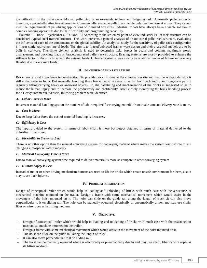
To carry out the analysis, it is difficult to show the uniform distribution of load over the entire span, so the total load acting on
the chassis is distributed over 15 points on the chassis as shown figure 4, the intensity of load at each point is 0.49 KN.
Fig. 4: Distribution of Forces Over 15 Points in Brick handling system
As the solution is defined the software is allow to solve the entire problem and generate the results. As soon as the results are
generated, it can be saved with their graphical representations figures or graphs. At this point, the Finite element model with all
the necessary information is exported for solution in Finite element Solver- NASTRAN.
Displacement Counter Plot
The result of counterplot for the displacement is shown in fig below.
Max. Dislpacement = 1.56mm
Fig. 5: Displacement contour plot after analysis of assembly for frame (conventional model)
Vonmisses Stress
Vonmisses stresses is used to check whether the design will withstand the given load condition or not. Using this information it
is checked whether the maximum vonmisses stress induced in the material is more than strength of the material. It works mostly
well for most of the cases especially for ductile material. It is used for the distortion energy theory which is most preferred
failure theory in industry.
Vonmisses stress in rigid frame with horizontal member
The value of vonmisses stresses obtained after performing analysis of the component is 139 MPa.
Fig. 6: Vonmisses Stress contour plot after analysis in frame with horizontal member

Design, Analysis and Validation of Conceptual Bricks Handling Trailer (IJIRST/ Volume 3 / Issue 02/ 035)
All rights reserved by www.ijirst.org 196
FE Results
Vonmisses Stress in frame without horizontal member
The value of vonmisses stresses obtained after performing analysis of the component is 76.5 MPa.
Fig. 7: Vonmisses Stress contour plot after analysis for frame without horizontal member (Deploying)
Maximum vonmisses stress in horizontal member
The value of vonmisses stresses obtained after performing analysis of the component is 139 MPa.
Fig. 8: Max. vonmisses stress in horizontal member
Maximum vonmisses stress in columns
The effect of vonmisses stresses in columns after analysis is shown below.
Fig. 9: Max. von misses stress in column
Design, Analysis and Validation of Conceptual Bricks Handling Trailer (IJIRST/ Volume 3 / Issue 02/ 035)
All rights reserved by www.ijirst.org 197
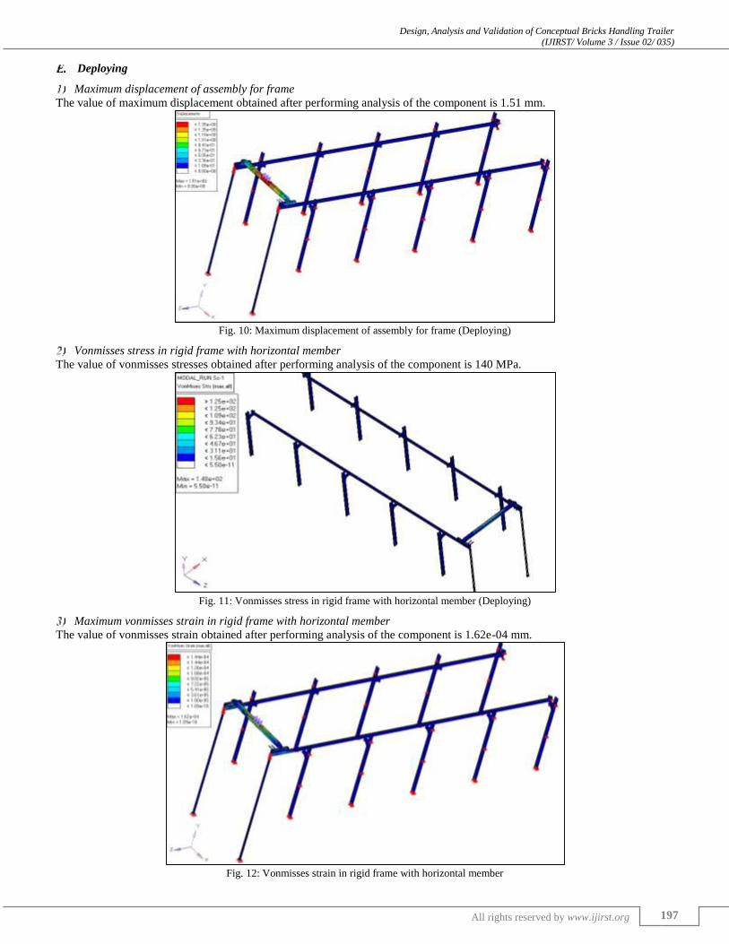
Deploying
Maximum displacement of assembly for frame
The value of maximum displacement obtained after performing analysis of the component is 1.51 mm.
Fig. 10: Maximum displacement of assembly for frame (Deploying)
Vonmisses stress in rigid frame with horizontal member
The value of vonmisses stresses obtained after performing analysis of the component is 140 MPa.
Fig. 11: Vonmisses stress in rigid frame with horizontal member (Deploying)
Maximum vonmisses strain in rigid frame with horizontal member
The value of vonmisses strain obtained after performing analysis of the component is 1.62e-04 mm.
Fig. 12: Vonmisses strain in rigid frame with horizontal member

Design, Analysis and Validation of Conceptual Bricks Handling Trailer (IJIRST/ Volume 3 / Issue 02/ 035)
All rights reserved by www.ijirst.org 198
Maximum vonmisses stress in frame without horizontal member
The value of vonmisses stresses obtained after performing analysis of the component is 87 MPa.
Fig. 13: Vonmisses stress in rigid frame without horizontal member
Maximum vonmisses stress in horizontal member
The value of vonmisses stresses obtained after performing analysis of the component is 140 MPa.
Fig. 14: Vonmisses stress in horizontal member
Optimization
Since the stress in the above part was low as 80 MPa, after reducing the thickness of the section was reduced to 3mm & 2mm.
Mass applied on the frame.
Previous -310kg
Now – 220kg
Fig. 15: Reduction in thickness which causes reduction in stress.
Maximum Displacement in Rigid Frame with Horizontal Member
The value of maximum displacement obtained after performing analysis of the component is 1.74 mm.

Design, Analysis and Validation of Conceptual Bricks Handling Trailer (IJIRST/ Volume 3 / Issue 02/ 035)
All rights reserved by www.ijirst.org 199
Fig. 16: Maximum displacement in rigid frame with with horizontal member after optimization
Maximum vonmisses stress in rigid frame with with horizontal member
The value of vonmisses stresses obtained after performing analysis of the component is 148 MPa.
Fig. 17: Maximum vonmisses stress in rigid frame with with horizontal member after optimization
Maximum vonmisses strain in rigid frame with horizontal member
The value of vonmisses strain obtained after performing analysis of the component is 2.60e-04 mm.
Fig. 18: Vonmisses strain in rigid frame with horizontal member after optimization

Design, Analysis and Validation of Conceptual Bricks Handling Trailer (IJIRST/ Volume 3 / Issue 02/ 035)
All rights reserved by www.ijirst.org 200
Vonmisses stress in rigid frame without horizontal member
The value of vonmisses stresses obtained after performing analysis of the component is 98 MPa.
Fig. 19: Vonmisses stress in rigid frame without horizontal member after optimization
Maximum Vonmmises stress in columns
The value of vonmisses stresses obtained after performing analysis of the component is 89 MPa.
Fig. 20: Vonmisses stress in columns after optimization
VII. CALCULATIONS
Area of brick = 97× 212 = 20564 mm2
Area of pallet = 1000 × 1000
Number of bricks = 1000×1000
20564= 48.62 ≅ 48
Pallet size:
Fig. 21: Size of Pallet Fig. 22: Size of trailer

Design, Analysis and Validation of Conceptual Bricks Handling Trailer (IJIRST/ Volume 3 / Issue 02/ 035)
All rights reserved by www.ijirst.org 201
So the truck can load 10 pallets, each pallet can contain 50 bricks. Thus the dimension of each pallet would be 1000 × 1000
mm2.
Each pallet has 4 layer of bricks.
Total number of bricks in each pallet = 4×50 = 200 bricks.
Weight of each bricks = 3.5kg (wet)
Weight of bricks in 7 pallets = 3.5×200 =700 kg
Weight of pallet=50 kg
Total weight = 750 kg
Total force acting = 750×9.81= 7357.5 N
Fig. 23: Central loading on beam
∑ fy = 0
Ra + Rb = 7357.5 N (1)
∑ Ma = 0
4089.13 × 817.66 = Rb×1635.33
3343538.48 = 1635.33×Rb
Ra = Rb = 2044.56 N
∑ Mc = 2044.56 × 817.66
∑ Mc = 1671759.017 N/mm2
I = 1048816.89 mm4
We know that, M
I =
σ
Y
𝜎 = 3366424.125 × 46
1048816.89
𝜎 = 147.647 N ⁄mm2
Case 1
Fig. 24: Loading on beam at some distance from a point
∑ fy = 0
Ra + Rc = 7357.5N (2)
∑ Ma = 0
7357.5 × 457.55 − Rc ×1030 = 0
Rc = 3268.37N
Ra + Rc = 7357.5
Ra = 7357.5 − 3268.37
Ra = 4089.13N
Ma = Mc = 0
MB = 4089.13 × 457.55
MB = 1870981.431N-mm
Now, M
I =
σ
Y
σ = 1870981.4315 × 46
1048816.89
σ = 82.059 N⁄mm2
Case 2
Column analysis
Since, the load acting on above calculation would be the force acting on column (assumption).
Compressive stress

Design, Analysis and Validation of Conceptual Bricks Handling Trailer (IJIRST/ Volume 3 / Issue 02/ 035)
All rights reserved by www.ijirst.org 202
σc = F / A
F = Ra = 4089.13
Area of I section column = Hd + 2hD
= (68.02× 4.04) + [2 × (6.02 × 40)]
Area = 756.4mm2 ≅ 767.58
σc = F / A
σc = 5.327𝑁 𝑚𝑚2⁄
I = 767430.01 mm4
Buckling load (both ends pinned)
Pcr=π2×E×I
I2
Pcr= π2×200000 ×767430
1809.24×1809.24
Pcr= 462312.57N
I = 110746.62mm4
Buckling Load for outside column
l = (1809.24 + 1500)
Pcr = π2×E×I
I2
Pcr = π2 ×200000×110746.62
3309.242
Pcr = 19941.78 N
Case 3:
Longitudinal member between two columns.
I = 775549.83 mm4
Fig. 25: Loading on longitudinal member between two columns
fy = 0
Ra + Rb = 4089.13
Ma = 0
4089.13 × 817.66 = Rb× 1635.33
Ra= Rb= 2044.56N
∑ Mc = 2044.56 × 817.66
∑ Mc = 1671759.017
Now, M
I =
σ
Y
σy=1671759.01 ×40.3
775549.83
σy = 86.869 N⁄mm2
VIII. RESEARCH METHODOLOGY
Various steps involved in study of nonstandard design of brick handling system are:
Data accumulation: Brick and TATA TRUCK2515 body selected for the analysis. From a local manufacturer all design
data related to dimensions of truck body and brick is obtained. With the help of vernier caliper measured the thickness of
all components and connection between components studied.
CAD model generation: as per design data obtained . A cad model generated by using CAD software Solidworks.
Finite Element Model generation: A finite element model of truck body has generated using CAD model in hypermesh. As
per geometry dimensions suitable element configurations used for meshing. mesh was generated according to the set
criteria. Material and elemental properties was assigned to the mesh.
Modal analysis of the truck body using FEA: we perform modal analysis, for finding the mode shapes and the different
vibrating frequencies. For this purpose we formed two load collectors: spc & eigrl . lay the constraint to the model and
process it for solver.
Design, Analysis and Validation of Conceptual Bricks Handling Trailer (IJIRST/ Volume 3 / Issue 02/ 035)
All rights reserved by www.ijirst.org 203
Static analysis of the truck body using FEA: we perform static analysis, for finding stresses and displacement for applied
load. For this purpose we form 2 load collectors: 1 spc & force . lay the constraint to the model and process it for solver.
Altering the design of these areas. Since there was a scope for optimization in the model, we took iterative steps and
changed the thickness of the channels and front shaft..
Results discussion: The comparative study of the result of original model and modified model was carried out. To draw a
conclusion.
IX. CONCLUSION
In this project the various activities that are involved are:
Gathering the functional and structural requirement of brick handling system.
Making General arrangement drawings.
Hand Calculations.
CAD model generation.
Finite element model generation (Pre-Processing).
Finite Element Analysis.
Addressing the change request from customer.
FEA of the updated design.
Publishing of drawings of the final design.
To provide bricks in time at the construction site and that too without damage is still a challenge in India. But manually
handling these bricks cause workers to suffer from back injury and long-term pain if regularly lifting/carrying heavy or awkward
objects. So, the palletizing and mechanization of the bricks is suggested so as to reduce the human injury and to increase the
productivity and profitability.
This proposed design of brick handling system in the heavy commercial vehicle can revolutionize the construction industry
through significant labour savings and increased productivity.
In this project the various activities that are involved are:
Gathering the functional and structural requirement of brick handling system.
Making General arrangement drawings.
Hand Calculations.
CAD model generation.
Finite element model generation (Pre-Processing).
Finite Element Analysis.
Addressing the change request from customer.
FEA of the updated design.
Publishing of drawings of the final design
ACKNOWLEDGMENTS
We would like to take this opportunity to express our deepest gratitude to all those who have support us and helped us to make
this paper a reality.We are highly indebted to Prof. R. R. Gandhe for his guidance and constant supervision and also for his
support in completing the paper.
In conclusion, we would like to thank our parents and colleagues for their kind co-operation and investing their time, and
willingly helping us with their abilities to make this paper a reality.
REFERENCES
[1] A.D.Anjikar, “Design, Development of Overhead Monorail for Material Handling System For food Processing Industry” ISSN : 2249-5762, Vol. 3, Issue 2, May - Oct 2013
[2] Du-Ming Tsai, “Modeling and analysis of three-dimensional robotic palletizing systems for mixed carton sizes”.
[3] Sourabh R. Dinde, Rajashekhar S. Talikoti, “Structural Behavior Of Industrial Pallet Rack With Braced And Unbraced Frames” [4] John Wiley, Sons,"Material Handling System Design".
[5] Luke Meakin, Peter Saxby,"Hatch Design Fundamentals for Drive Systems on Conveyors. [6] Daniel Clénet,"Optimizing Energy Efficiency of Conveyors".
[7] Tomas H Orihuela,"Design of Monorail Systems".
[8] PIP, Material Handling Guide [9] American Institute of Steel Construction (Aisc), Manual ofSteelconstruction,allowable Stress Design, 9th Edition.
[10] American Institute of Steel Construction (Aisc), Manual ofSteel Construction, load and Resistance Factor Design, 3rdEdition.
[11] Crane Manufacturers Association of America, Inc. (Cmaa)Specification No.74, Revised 2000, Specifications For Top Running And Under Running Single girder Electric OverheadCranes Utilizing Under Running Trolley Hoists.
[12] Material Handling Industry of America (Mhia).