Design & Analysis of a 500 lbf Liquid Oxygen and Liquid ...
76
University of Texas at El Paso DigitalCommons@UTEP Open Access eses & Dissertations 2017-01-01 Design & Analysis of a 500 lbf Liquid Oxygen and Liquid Methane Rocket Engine Daniel Eduardo Vargas University of Texas at El Paso, [email protected] Follow this and additional works at: hps://digitalcommons.utep.edu/open_etd Part of the Mechanical Engineering Commons is is brought to you for free and open access by DigitalCommons@UTEP. It has been accepted for inclusion in Open Access eses & Dissertations by an authorized administrator of DigitalCommons@UTEP. For more information, please contact [email protected]. Recommended Citation Vargas, Daniel Eduardo, "Design & Analysis of a 500 lbf Liquid Oxygen and Liquid Methane Rocket Engine" (2017). Open Access eses & Dissertations. 571. hps://digitalcommons.utep.edu/open_etd/571
Transcript of Design & Analysis of a 500 lbf Liquid Oxygen and Liquid ...

University of Texas at El PasoDigitalCommons@UTEP
Open Access Theses & Dissertations
2017-01-01
Design & Analysis of a 500 lbf Liquid Oxygen andLiquid Methane Rocket EngineDaniel Eduardo VargasUniversity of Texas at El Paso, [email protected]
Follow this and additional works at: https://digitalcommons.utep.edu/open_etdPart of the Mechanical Engineering Commons
This is brought to you for free and open access by DigitalCommons@UTEP. It has been accepted for inclusion in Open Access Theses & Dissertationsby an authorized administrator of DigitalCommons@UTEP. For more information, please contact [email protected].
Recommended CitationVargas, Daniel Eduardo, "Design & Analysis of a 500 lbf Liquid Oxygen and Liquid Methane Rocket Engine" (2017). Open AccessTheses & Dissertations. 571.https://digitalcommons.utep.edu/open_etd/571
DESIGN & ANALYSIS OF A 500 LBF LIQUID OXYGEN AND
LIQUID METHANE ROCKET ENGINE
DANIEL VARGAS FRANCO
Master’s Program in Mechanical Engineering
APPROVED:
Ahsan Choudhuri, Ph.D., Chair
Jack Chessa, Ph.D.
Luis Rene Contreras, Ph.D.
Charles H. Ambler, Ph.D.
Dean of the Graduate School

Copyright ©
by
Daniel Vargas Franco
2017
DESIGN & ANALYSIS OF A 500 LBF LIQUID OXYGEN AND
LIQUID METHANE ROCKET ENGINE
by
DANIEL VARGAS FRANCO, B.S.ME
THESIS
Presented to the Faculty of the Graduate School of
The University of Texas at El Paso
in Partial Fulfillment
of the Requirements
for the Degree of
MASTER OF SCIENCE
Department of Mechanical Engineering
THE UNIVERSITY OF TEXAS AT EL PASO
December 2017

iv
Acknowledgements
Foremost, I would like to express my gratitude to my advisor Dr. Ahsan Choudhuri for the
useful comments, engagement, and continuous support of my Master’s study and for giving me
the opportunity to conduct research at the UTEP Center for Space Exploration and Technology
Research (cSETR). I would also like to thank the other members of my committee, Dr. Chessa and
Dr. Luis Rene Contreras for participating in the review of my research.
My sincere thanks to the National Aeronautics and Space Administration Johnson Space
Center propulsion branch for your guidance, support, and willingness to help my research team on
complex rocket engine topics that are invaluable for a successful engine design.
I would like to extend my gratitude to all the NASA mentors I had on my two internships.
Thank you for giving me the opportunity to intern with NASA to gain invaluable experience and
helping me grow as a professional. And finally, I would like to thank my friends and family, they’re
the reason I continue to strive for success in my life.
v
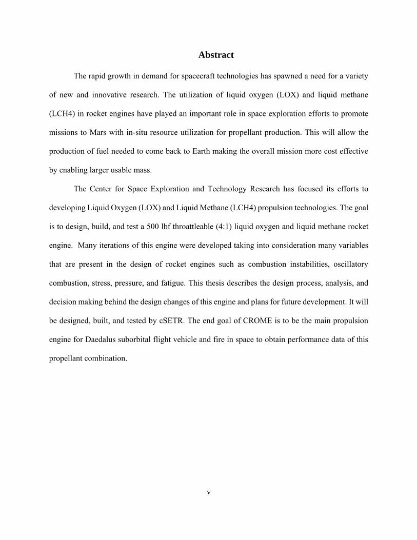
Abstract
The rapid growth in demand for spacecraft technologies has spawned a need for a variety
of new and innovative research. The utilization of liquid oxygen (LOX) and liquid methane
(LCH4) in rocket engines have played an important role in space exploration efforts to promote
missions to Mars with in-situ resource utilization for propellant production. This will allow the
production of fuel needed to come back to Earth making the overall mission more cost effective
by enabling larger usable mass.
The Center for Space Exploration and Technology Research has focused its efforts to
developing Liquid Oxygen (LOX) and Liquid Methane (LCH4) propulsion technologies. The goal
is to design, build, and test a 500 lbf throattleable (4:1) liquid oxygen and liquid methane rocket
engine. Many iterations of this engine were developed taking into consideration many variables
that are present in the design of rocket engines such as combustion instabilities, oscillatory
combustion, stress, pressure, and fatigue. This thesis describes the design process, analysis, and
decision making behind the design changes of this engine and plans for future development. It will
be designed, built, and tested by cSETR. The end goal of CROME is to be the main propulsion
engine for Daedalus suborbital flight vehicle and fire in space to obtain performance data of this
propellant combination.
vi
Table of Contents
Acknowledgements ........................................................................................................................ iv
Abstract ........................................................................................................................................... v
Chapter 1: Introduction ................................................................................................................... 1
1.1 Background ...............................................................................................................2
1.2 Green Propellants ......................................................................................................2
1.3 Previous Work ...........................................................................................................3
Chapter 2: CROME Development Purpose .................................................................................... 5
2.1 Deadalus Vehicle Overview .........................................................................................5
2.2 Research Opportunities ................................................................................................6
CHAPTER 3: Liquid-Propellant Rocket Engines .......................................................................... 8
3.1 Pintle Injector ...............................................................................................................9
Chapter 4: CROME Design Requirements ................................................................................... 11
4.1 Torch Igniter Requirements ........................................................................................11
4.2 Operational Requirements ..........................................................................................12
4.2.1 Mixture Ratio .............................................................................................13
4.2.2 Material ......................................................................................................14
4.2.3 Fuel Film Cooling ......................................................................................15
4.2.4 Nozzle Shape & Expansion Ratio ..............................................................15
4.2.5 Envelope ....................................................................................................17
4.2.6 Chamber Pressure (Pc) ...............................................................................19
4.2.7 Propellant Feed System..............................................................................19
Chapter 5: Combustion Instabilities ............................................................................................. 21
5.1 Acoustic Dampening Mechanisms .............................................................................23
Chapter 6: CROME Design Analysis ........................................................................................... 25

vii
6.1 Thrust Chamber ..........................................................................................................25
6.2 Injector Body ..............................................................................................................32
6.3 Pintle Manifold ...........................................................................................................42
Chapter 7: Valves & Instrumentation ........................................................................................... 49
Chapter 8: Future Work ................................................................................................................ 56
Chapter 9: Conclusion .................................................................................................................. 58
References ..................................................................................................................................... 59
Appendix ....................................................................................................................................... 61
A.1 Thrust chamber wall thickness analysis ....................................................................61
A2 Injector Body/Chamber Flange Bolt Analysis ...........................................................62
A3 Manifold Cap Bolt Analysis .......................................................................................63
Vita ..……………………………………………………………………………………………...65
viii
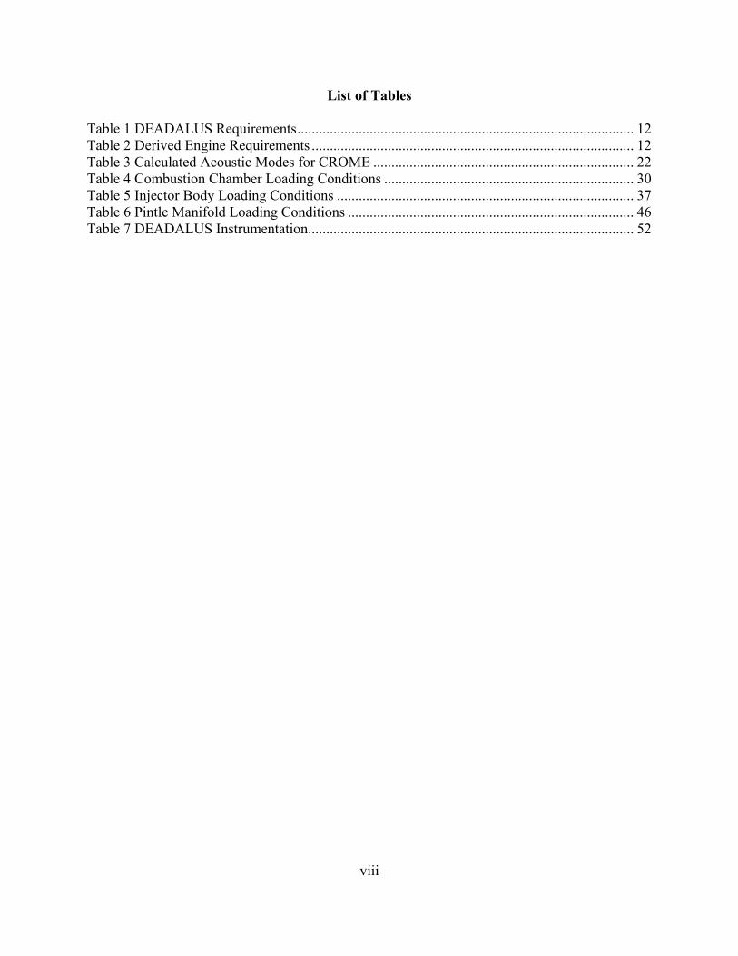
List of Tables
Table 1 DEADALUS Requirements ............................................................................................. 12
Table 2 Derived Engine Requirements ......................................................................................... 12
Table 3 Calculated Acoustic Modes for CROME ........................................................................ 22
Table 4 Combustion Chamber Loading Conditions ..................................................................... 30
Table 5 Injector Body Loading Conditions .................................................................................. 37
Table 6 Pintle Manifold Loading Conditions ............................................................................... 46
Table 7 DEADALUS Instrumentation.......................................................................................... 52

ix
List of Figures
Figure 1 Morpheus Main Engine Test ............................................................................................ 4
Figure 2 NASA Design of RCS ...................................................................................................... 5
Figure 3 DEADALUS Flight Profile .............................................................................................. 6
Figure 4 Rocket Engine Chamber and Nozzle Configuration ........................................................ 9
Figure 5 Pintle Injector Design ....................................................................................................... 9
Figure 6 Inner Flow Only (Dressler & Bauer, 2000) .................................................................... 10
Figure 7 Outer Flow Only (Dressler & Bauer, 2000) ................................................................... 10
Figure 8 Combined Flows (Dressler & Bauer, 2000) ................................................................... 10
Figure 9 Torch Igniter Testing ...................................................................................................... 11
Figure 10 Torch Igniter Schematic ............................................................................................... 11
Figure 11 Specific Impulse (Isp) vs. Mixture Ratio (MR) for LOX/LCH4 Propellants ............... 14
Figure 12 Isp vs. Expansion Ratio @ 235 psia Chamber Pressure ............................................... 16
Figure 13 Thrust vs Expansion Ratio at 235 psi Chamber Pressure ............................................. 16
Figure 14 Thrust Chamber Wight Increase Estimate vs Expansion Ratio .................................... 17
Figure 15 CROME Components ................................................................................................... 18
Figure 16 CROME Size Envelope ................................................................................................ 18
Figure 17 High-Frequency Modes ................................................................................................ 21
Figure 18 Acoustic Absorber Configuration................................................................................ 24
Figure 19 Thrust Chamber First Iteration ..................................................................................... 27
Figure 20 Last Iteration of Thrust Chamber Geometry ................................................................ 28
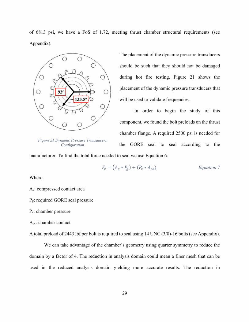
Figure 21 Dynamic Pressure Transducers Configuration ............................................................. 29
Figure 22 Combustion Chamber Mesh ......................................................................................... 30
Figure 23 Chamber Stress Contours ............................................................................................. 32
Figure 24 Injector Body First Iteration ......................................................................................... 32
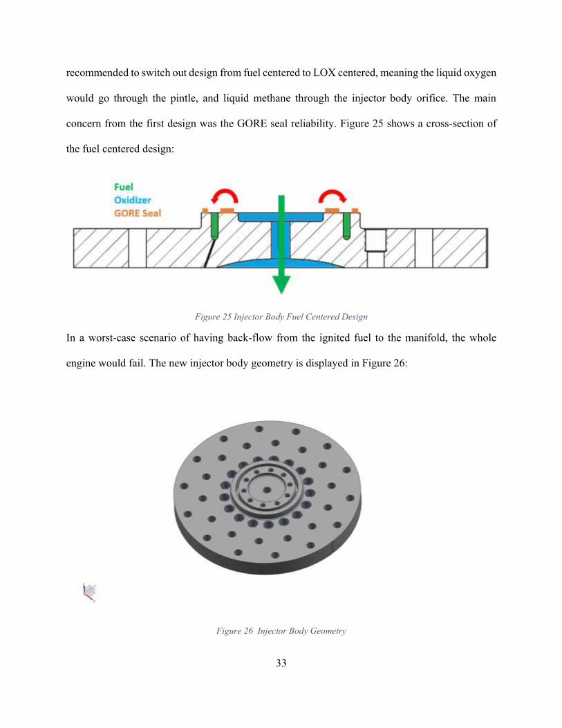
Figure 25 Injector Body Fuel Centered Design ............................................................................ 33
Figure 26 Injector Body Geometry .............................................................................................. 33
Figure 27 Bolt Preload and GORE Seal Load Conditions Top Distribution ............................... 35
Figure 28 Bolt Preload and GORE Seal Load Conditions Bottom Distribution ......................... 35
Figure 29 Injector Body Mesh ..................................................................................................... 36
Figure 30 Injector Body Mesh Side View ................................................................................... 37
Figure 31 Injector Body Stress Contours ..................................................................................... 40
Figure 32 Injector Body Thermal Gradient ................................................................................. 41
Figure 33 Pintle Primary and Secondary Holes ............................................................................ 42
Figure 34 Pintle Manifold First Iteration (Fuel Centered) ............................................................ 43
Figure 35 Pintle Manifold Geometry ............................................................................................ 43
Figure 36 Pintle Injector Streams Angular Relation ..................................................................... 44
Figure 37 Bolt Area (left) GORE seal Area (right) ...................................................................... 45
Figure 38 Pintle Manifold Mesh ................................................................................................... 46
Figure 39 Pintle Manifold Thermal Gradient ............................................................................... 48
Figure 40 Habonim Ball Valves (left) 60° v-port (right) .............................................................. 50
Figure 41 Connector & Thermal Contour ..................................................................................... 51
Figure 42 Valve-Actuator Assembly ............................................................................................ 51
Figure 43 Rendering of cSETR's tRIAc ....................................................................................... 56

x
Figure 44 Water Test Setup .......................................................................................................... 57

1
Chapter 1: Introduction
Liquid Oxygen (LOX) and Liquid Methane (LCH4) is the most promising rocket fuel
towards the journey to Mars. In the past, other better performing propellant combinations have
been employed in the aerospace industry, like Liquid Hydrogen and LOX. However, using LOX
and LCH4 has a lot of benefits over traditional hydrogen and LOX launch systems. Hydrogen
gives a higher specific impulse but all the modifications required to deal with hydrogen negate that
gain. This is due to methane being denser which would require much smaller tanks making the
overall design much lighter. Also, methane is more stable in space over long periods of time vs
hydrogen/LOX and does not need highly insulated cryogenic tanks. Methane has a boiling point
much closer to that of oxygen allowing a simple bulkhead design. Most importantly, it can be
produced from local sources on Mars using in-situ resource utilization (ISRU) technology. This
technology consists in the practice of leveraging resources found on other astronomical objects to
fulfill the requirements to come back to Earth. Which would make the mission more affordable
and it allows the mission to carry more payload instead of fuel weight.
This has led companies to develop their own liquid methane propulsion systems all with
the same purpose of enabling the technology to explore Mars and other space entities. Some
examples are the Space X Raptor engine and the Blue Origin BE-4 engine.
The UTEP Center of Space Exploration and Technology Research (cSERTR) in
partnership with the National Aeronautics and Space Administration (NASA) has been leading
research center for the advancement of LOX and LCH4 propulsion technologies. This paper
discusses the design and analysis process used to develop the last version of Centennial Restartable
Oxygen Methane Engine (CROME), a throattable 500 lbf LOX/LCH4 rocket engine. It will
2
include detailed description of the assumptions made and finite element analysis for each major
component.
1.1 Background
The cSETR has focused its efforts in the use of methane as a propellant. Nowadays, space
exploration is relatively new and sending anything to space requires lot of money and planning.
Because of this, it would be beneficial to be able to use all the resources available in space. In-situ
resource utilization (ISRU) technology can provide the propellant necessary to come back to Earth.
ISRU can reduce the mass and cost of space exploration architectures, reducing the amount of
payload that must be launched from Earth. It is well known, that there is water on Mars. So,
propellant can be produced from the Martian surface using two chemical reactions, water
electrolysis and the Sabatier Reaction.
The CROME engine will be the main propulsion system for DEADALUS. The cSETR
DEADALUS project is based on NASA’s Project Morpheus, which also utilized a pintle injector.
This would become beneficial during the project since doubts and questions about design could be
addressed to the NASA team in Johnson Space Center in Houston, TX. The end goal of the
DEADALUS and CROME project is to successfully operate an integrated LOX/LCH4 engine.
1.2 Green Propellants
The propellants used have large biological impacts. Ground-based impacts can vary from
groundwater contamination to explosions caused by mishandling of propellants. Hypergolic
propellants are among the most efficient rocket fuels we know but are highly toxic and unstable.
Also, these propellants have high impact on the atmosphere generally caused by the interaction of

3
the propellant exhaust with the atmosphere; biological impacts tend to focus on the toxicology and
corrosiveness of propellants. This is why we focused our research on liquid methane, it is easier
to handle and does not ignite unless properly atomized and mixed with an oxidizer. LCH4 is
suitable for ISRU and can lower the negative impact on our atmosphere. The term “green
propellant” is often confused because many can assume it has no negative effect on the
environment, this is almost physically impossible, any propellant affects the environment in some
way.
Green propulsion will depend on its ability to satisfy the two main drivers for its
development, performance and lower costs. Currently, the atmospheric impact remains low
because launch rates remain low, but it is important to start limiting environmental effects in order
to pursue more efficient interplanetary explorations.
1.3 Previous Work
Not only has NASA done work on LO2-LCH4 propulsion technologies but private companies
like Blue Origin and SpaceX have also invested in them. The main objective for both companies
is reusability. This is due to their desire of decreasing the cost to reach outer space. Their work
includes the achievement of vertical propulsive landing. Blue Origin achieved this with New
Shepard and Space X with Falcon 9. With this they got closer to their goal of reusability of space
crafts. Also, the ability of generating the LO2-LCH4 fuel on the landing site will help the human
missions of space exploration.
NASA has its own vehicle capable of vertical take-off and landing (VTOL) which is called
Morpheus. This planetary lander was built with the purpose to test the autonomous landing and
hazard avoidance and the integration of LO2-LCH4 propulsion (Hart & Devolites, 2014). This

4
craft allowed the successful demonstration of an autonomous and unmanned landing by picking a
safe landing zone. Morpheus had three different levels of test at Kennedy Space Center (KSC).
The first one was a hot-fire test which was performed to see the fire sequence initiated with the
control software. After that one, tethered testing followed. The vehicle was suspended from a crane
and its navigation and control systems helped it hover in midair. One of the tethered tests was
unsuccessful but this helped to prepare the vehicle better. The final test was a free flight test. In
2012 on one of the free flight tests Morpheus lost communication and most of the vehicle was lost.
A second Morpheus was built, but this time around the tethered flights were more extraneous.
Then, it was able to land safely on the free flight missions.
The main drivers of the Morpheus propulsion system developed by
NASA was to produce a low cost vehicle. The first iteration of the Morpheus
project used an engine called HD, designed to provide 2,700 lbf of thrust.
This project has been used as a baseline for the DEADALUS project.
Lessons learned and approach used by the team in charge of the Morpheus
project helped the cSETR to define our engine. UTEP and JSC have a
partnership and many NASA engineers gave us constant mentoring and
shared the knowledge to benefit the development of our project. This thesis
and project borrows the concepts and design features of the Morpheus and
improves some of its aspects.
Figure 1 Morpheus Main
Engine Test

5
Chapter 2: CROME Development Purpose
The Centennial Restartable Oxygen Methane Engine (CROME) will be used as the main
propulsion system for the DEADALUS vehicle. Both, vehicle and engine, were designed in
parallel so many of the engine parameters and requirements are derived from DEADALUS.
2.1 Deadalus Vehicle Overview
DEADALUS is a suborbital demonstration vehicle and its goal is to evaluate performance
under microgravity conditions incorporating methane propulsion technologies. The propulsion
system includes the main engine and a reaction control engine (RCE), a derivative of previous
work conducted both by NASA and cSETR, which is designed around being integrated within this
vehicle. The RCEs are the secondary source of propulsion for this vehicle. Through the partnership
with NASA, the cSETR was able to obtain the RCE CAD model used on the Morpheus vehicle.
Upon this design modifications were made to improve performance.
Figure 2 NASA Design of RCS
6
This RCE is capable of providing 5 lbf of thrust at sea level based on like-impinging
elements going through the combustion chamber and then ignited using a spark plug. A module
was designed to accommodate the RCEs, valves, and instrumentation.
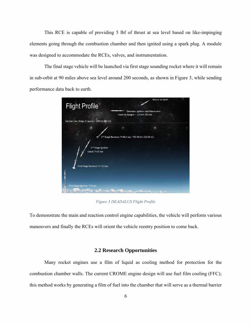
The final stage vehicle will be launched via first stage sounding rocket where it will remain
in sub-orbit at 90 miles above sea level around 200 seconds, as shown in Figure 3, while sending
performance data back to earth.
Figure 3 DEADALUS Flight Profile
To demonstrate the main and reaction control engine capabilities, the vehicle will perform various
maneuvers and finally the RCEs will orient the vehicle reentry position to come back.
2.2 Research Opportunities
Many rocket engines use a film of liquid as cooling method for protection for the
combustion chamber walls. The current CROME engine design will use fuel film cooling (FFC);
this method works by generating a film of fuel into the chamber that will serve as a thermal barrier
7
between the combustion gases and the combustion chamber. This method was selected due to its
simplicity, but future versions will attempt to implement a regenerative cooling design.
Additive manufacturing is a growing technology which process consists of digital 3D
design data to build up components in layers by depositing material. The benefits from this
technology lie in those areas where conventional manufacturing reaches its limitations. It provides
a high degree of design freedom, optimization and integration of functional features. Future
versions of CROME will try to successfully incorporate components made by using additive
manufacturing.
8
CHAPTER 3: Liquid-Propellant Rocket Engines
The main function of a rocket engine is to generate thrust through combustion. The force
generated transmits a momentum to the combustion products and a momentum in the opposite
direction. The thrust generated by a rocket is the reaction experienced by the structure when
ejecting high velocity gases. Thrust can be divided into two terms, momentum and pressure thrust.
Momentum thrust is the product of the propellant mass flow rate and the exhaust velocity relative
to the vehicle and it accounts for the majority of the thrust generated by a rocket. Pressure thrust
is the product of the cross sectional area of the exhaust jet leaving the vehicle and the difference
between the exhaust pressure and the surrounding fluid pressure (ambient pressure) (Huzel &
Huang, 1992).
The operation of a rocket engine system is independent of its environment except for
effects on performance cause by ambient air pressure. A conventional engine configuration is
shown in Figure 4. A converging nozzle accelerates the gases until it reaches the throat; because
of compressible flow effects, the gas reaches sonic velocity or Mach 1. When the gases reach this
velocity, increasing the flow area further increases the velocity of the gases. Because of this, to
reach sonic velocity, a diverging nozzle must be used. Figure 4 shows a chamber and nozzle
configuration:

9
Figure 4 Rocket Engine Chamber and Nozzle Configuration
3.1 Pintle Injector
CROME will use a pintle injector as
the injection method. The pintle injector
rocket engine is fundamentally different
from other rocket engines, which nearly
universally employ a series of separate
propellant injection orifices distributed
across the diameter of the headend of the
combustion chamber. The pintle’s central,
singular injection geometry results in a
combustion chamber flow field that varies greatly from that of conventional rocket engines. These
differences result in certain operational characteristics of great benefit to rocket engine design,
Figure 5 Pintle Injector Design

10
performance, stability, and test flexibility (Atyam & Hguyen, 2015). The basic concept of the
bipropellant pintle injector is shown in Figure 5.
The 90°, axial-radial impingement of the two
propellant streams combined with the specific
geometry of the resulting atomization and mixing
"fan" is fundamental to the pintle injector providing
both high combustion efficiency and inherent
combustion stability. The impingement point is within
the chamber distance down the axis of the post from
the injector face, also known as the skip distance.
Figure 6, 7, and 8 show a representation of the annular
injection, radial injection, and the spray fan resulting
from the combined injected flows (Dressler & Bauer,
2000).
Pintle injectors are well known for their deep
throttling capabilities, low cost compared to impinging
type injectors, and high combustion efficiency. Pintle
injectors typically deliver high combustion efficiency
in the range of 96-99% (Dressler & Bauer, 2000). Deep
throttling is done using an actuation mechanism that
displaces the sleeve of the pintle post axially.
Figure 8 Combined Flows (Dressler & Bauer,
2000)
Figure 7 Outer Flow Only (Dressler & Bauer,
2000)
Figure 6 Inner Flow Only (Dressler & Bauer,
2000)

11
Chapter 4: CROME Design Requirements
The mission’s top level requirements became design drivers for this engine. As the design
process evolved, many iterations were conducted to fulfill mission requirements. Top level
requirements will be discussed on this chapter.
4.1 Torch Igniter Requirements
The torch ignition system was
designed as the source of ignition
for CROME. A swirl coaxial
igniter was fabricated after a series
of experiments to characterize
methane’s properties and
performance as a rocket fuel. This
type of igniter introduces oxygen
through an axial orifice while the
methane is injected in a tangential
swirl pattern around the
combustion chamber. The main
requirement of the igniter is that is
should ignite the propellants at
gaseous state.
Several iterations of the sparking system were manufactured in-house until it was decided
to use an already manufactured spark plug. This spark plug was smaller than the previous ones
Figure 10 Torch Igniter Schematic
Figure 9 Torch Igniter Testing
12
used allowing to place it closer to the methane injection ports. 100% ignition rate was achieved
with this method with the use of gaseous propellants. Two solenoid valves will be used to control
the flow going into the igniter. Additional instrumentation will be used to verify the pressure and
supplementary support will be used to attach the apparatus to the engine envelope.
4.2 Operational Requirements
The requirements discussed previously are shown in Table 1 and Table 2. Various
calculations were done using CEA (Chemical Equilibrium with Applications) and RPA (Rocket
Propulsion Analysis) software to accurately determine the thermodynamics properties of different
propellants to perform rocket engine analysis.
Table 1 DEADALUS Requirements
Requirement Definition / Value
Thrust, (Ft) 125 – 500 lbf (4:1 throttleability)
Operation Pressure 12.8 psia (ambient), and 0 psia (space)
Propellants LOX/LCH4 (Liquid Oxygen/Liquid Methane)
Propellant Tank Pressure 400 psia
Cooling Method Film Cooling
Reaction Control Engines 12
Table 2 Derived Engine Requirements
Requirement Definition / Value
Chamber Pressure (Pc) 70 – 235 psi
Specific Impulse (Isp) 227s (sea level), 330s (vacuum w/o cooling)
Injector Type Pintle Injector
13
Nozzle Shape &
Expansion Ratio (𝝐)
Bell Shape
𝜖: 1.6 for sea level testing, 30 for space
operation
Mixture Ratio Combustion: 2.7
Type Steady State Engine
Material Inconel 625 (Injector Components)
Inconel 715 (Thrust Chamber)
Cooling Method ≤ 30% fuel film cooling
Envelope ≤ 14.5 Diameter ; ≤ 24 “ Length
4.2.1 Mixture Ratio
To find the optimal mixture ratio (MR), a chart was generated using CEA and RPA using
a chamber pressure of 235 psi and our two propellants (LOX & LCH4) plotting the MR against
specific impulse (Isp). After analyzing the chart, we can see that that optimal mixture ratio is
around 2.7. The reason behind this is because this number allow us to have equal tank sizes. This
happens because the density of liquid oxygen is roughly 2.7 greater than the density of liquid
methane, leading to equal propellant volume. Having equal tank sizes simplifies engine design.

14
Figure 11 Specific Impulse (Isp) vs. Mixture Ratio (MR) for LOX/LCH4 Propellants
4.2.2 Material
Each component of the engine will be exposed to different loading conditions. The engine
will experience cryogenic temperatures from the propellants and hot temperatures due to
combustion. Because of this, the materials selected to manufacture this engine were Inconel 718
and Inconel 625. This material is ideal for aerospace applications because is compatible with LOX
and LCH4 and can withstand hot and cryogenic temperatures. Inconel 718 has a relatively high
melting temperature of 2300-2437 °F, however, the maximum temperature allowed will be 2000
°F during operation. Inconel 625 offers similar mechanical properties as Inconel 718, nonetheless,
Inconel 718 is stronger (180 vs 120 ksi ultimate strength at room temperature). Because of this,
the chamber will be made out of Inconel 718 due to the high temperature this part will be exposed.
Stainless Steel 316 will be used for the propellant lines going into the injector because it is the
easiest to find and a less expensive option to other alloys.
15
4.2.3 Fuel Film Cooling
During combustion, chamber walls can reach temperatures over 4500 °F, these
temperatures are able to melt any material by a large margin. As a result of this, a cooling method
is required. The method chosen was fuel film cooling (FFC) in which a percentage of the fuel
(30%) used for combustion is injected along the surface of the wall that acts as a thermal barrier
between the chamber wall and the combustion gases. This percentage was the same that NASA
Johnson Space Center Morpheus project used for their Morpheus LOX/LCH4 engine.
4.2.4 Nozzle Shape & Expansion Ratio
To reach supersonic velocity, the ratio between the exit pressure and chamber pressure has
to be lower than the critical pressure ratio. This pressure is defined in Equation 3:
𝑃𝑡
𝑃𝑐= (
2
𝑘+1)
𝑘
𝑘−1 Equation 1
Where:
Pt: pressure at the throat
Pc: chamber pressure at the nozzle
k: specific heat ratio of the gas
If the pressure ratio between Pe and Pc is greater than the critical pressure ratio, the flow
will not reach sonic conditions and the divergent nozzle will slow down the gas instead of increase
the velocity (Sutton & Biblarz, 2010). To achieve maximum performance in El Paso, TX the
expansion ratio has to deliver ideal expansion (Pe=Pa). Because the engine will throttle, is
preferable to use an under-expanded nozzle.
A space operation expansion ratio was selected due to weight constraint and dimensions
set by the vehicle and driven by the thrust and performance increase. The following picture shows
the analysis done to help select the expansion ratio comparing it with Isp, thrust, and weight:

16
Figure 12 Isp vs. Expansion Ratio @ 235 psia Chamber Pressure
Figure 13 Thrust vs Expansion Ratio at 235 psi Chamber Pressure
17
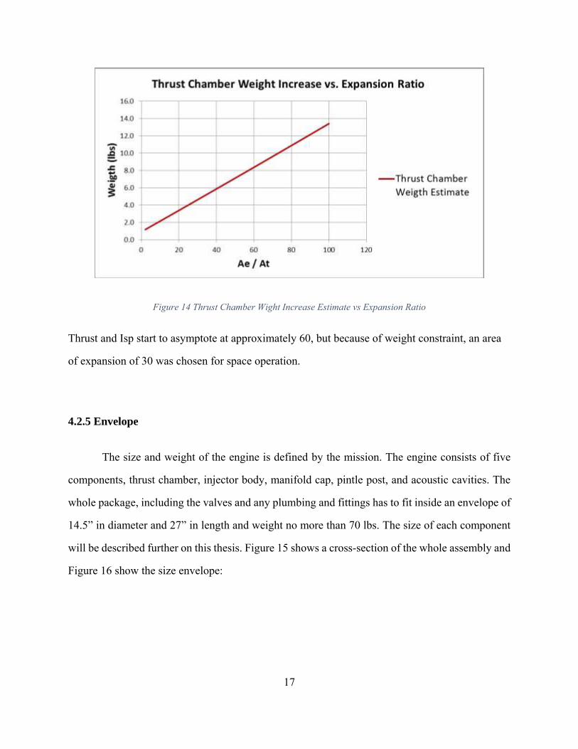
Figure 14 Thrust Chamber Wight Increase Estimate vs Expansion Ratio
Thrust and Isp start to asymptote at approximately 60, but because of weight constraint, an area
of expansion of 30 was chosen for space operation.
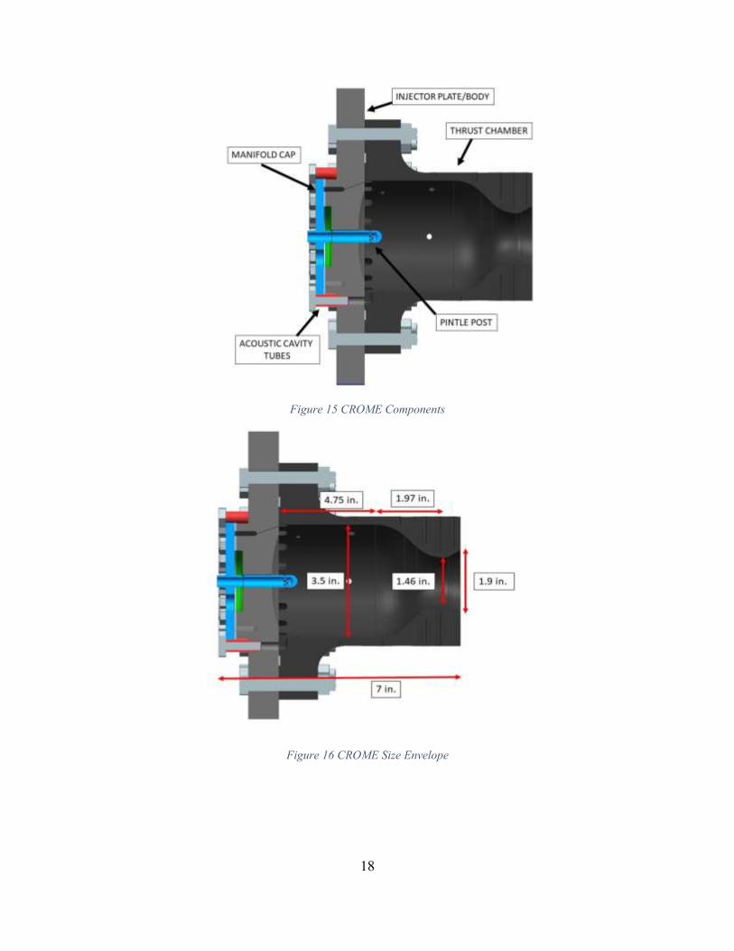
4.2.5 Envelope
The size and weight of the engine is defined by the mission. The engine consists of five
components, thrust chamber, injector body, manifold cap, pintle post, and acoustic cavities. The
whole package, including the valves and any plumbing and fittings has to fit inside an envelope of
14.5” in diameter and 27” in length and weight no more than 70 lbs. The size of each component
will be described further on this thesis. Figure 15 shows a cross-section of the whole assembly and
Figure 16 show the size envelope:
18
Figure 15 CROME Components
Figure 16 CROME Size Envelope

19
4.2.6 Chamber Pressure (Pc)
Chamber pressure was chosen according to the throttling requirement. The requirement
states the engine should have the capability to throttle to a ratio 4:1, that is, 125 lbf to 500 lbf. The
required pressure to have sonic flow at the throat is 35 psi at sea level. Because of this, it was
determined to choose 70 psi to be the low end thrust and 235 the maximum operating pressure.
4.2.7 Propellant Feed System
The propellant feed system is a key component for rocket engine design, it delivers the
propellants from the tanks to the thrust chamber. A pressure-fed design was chosen because we
are relying on the tanks to feed the propellants into the thrust chamber. In general, pressure-fed
engines have a more simple design because we do not need the use of turbopumps which will add
weight and are unreliable under space conditions.
The propellants would fill the lines as well as the propellant which would be left unused in
the tank after the flight is done. The tanks that will be used were sized according to the
requirements of the main engine. Preliminary design of these tanks was made based on the design
made by Morpheus. Johnson Space Center provided computed assisted drawings (CAD) and
various modifications were made to them in order to fulfill DEADALUS requirements.
Another important subject are the tanks that will be used for flight. For flight, tanks were
designed by the cSETR, they must allow storage of the two propellants and the pressurization gas
separately. They are used to pressurize the propellants and ensure that the engine will receive the
necessary fuel to burn and deliver thrust. They also must carry enough propellant to ensure that
main mission objectives and ancillary maneuvers can be achieved successfully. One of the most
important constraints for tank sizing was the DEADALUS size envelope. However, for the first

20
stages of testing, it was recommended to use 6K type cylinder by Air Liquide, one of the suppliers
at the tRIAc facility. Although it is more than the required amount, extra GN2 can be delivered for
purging purposes during testing.
21
Chapter 5: Combustion Instabilities
One of the most critical and most dangerous phenomena occurred in a rocket engine are
combustion instabilities. This is because if not treated with some form of dampening, they can lead
to engine failure due to destructive vibration. These vibrations can damage the chamber and/or
decrease engine efficiency. The design of the acoustic cavities for CROME used to lower the
impact of this behavior are discussed in detail in the thesis written by Jonathan Candelaria.
Combustion Instabilities have been recognized and studied since the beginning of rocket
engines in the 1930s. Combustion instabilities are oscillations produced largely by pressure. We
can see this behavior in almost all rocket engine programs and still there is no exact way to avoid
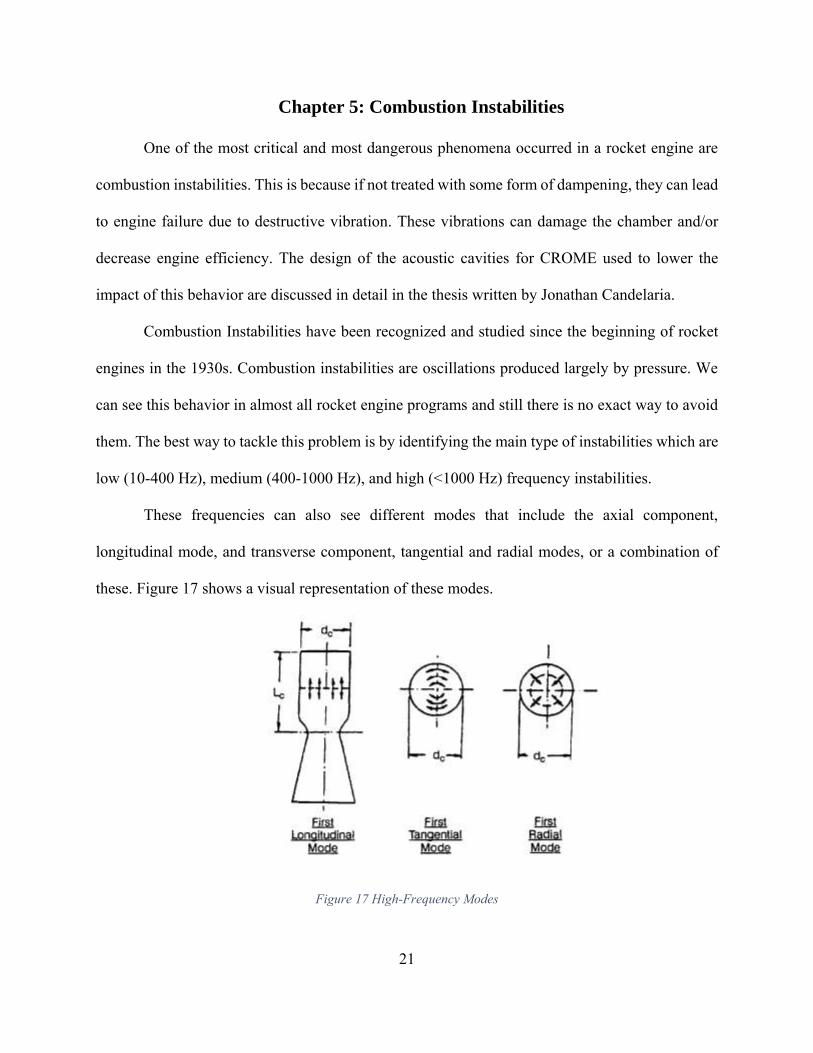
them. The best way to tackle this problem is by identifying the main type of instabilities which are
low (10-400 Hz), medium (400-1000 Hz), and high (<1000 Hz) frequency instabilities.
These frequencies can also see different modes that include the axial component,
longitudinal mode, and transverse component, tangential and radial modes, or a combination of
these. Figure 17 shows a visual representation of these modes.
Figure 17 High-Frequency Modes
22
These frequencies cause acoustic modes that equal that of cylindrical volume. Analysis
was done to estimate the corresponding resonant frequencies at which each mode will occur using
the following formula:
𝒇𝒎,𝒏,𝒒 =𝒄
𝟐𝝅√(
𝝀𝒎𝒏
𝑹𝒄)
𝟐
+ (𝒒𝝅
𝑳𝒄)
𝟐
, (𝑯𝒛) Equation 2
Where:
c: speed of sound
λ: transversal eigenvalues for tangential and radial mode
m,n: 0,1,2…
q: longitudinal mode number
Rc: combustion chamber diameter
Lc: effective acoustic length
The acoustic frequencies for CROME are shown in Table 3:
Table 3 Calculated Acoustic Modes for CROME
Acoustic Modes Resonant Frequency (Hz)
1L 5095.6
2L 10191.3
3L 15286.9
1T 6416.5
1T1L 8193.7
2T 10643.8
2T1L 11800.7
1R 13353.4
1R1L 14292.6
2R 24449.2
2R1L 24974.5
3T 14641.1
23
Through the calculations and models performed in MatLab we were able to identify the
three acoustic modes and its resonant frequencies which would have a greater impact to the engine.
These frequencies are the three highlighted rows in the Table 3. Now that we have identified them,
these will be the frequencies we will try to dissipate.
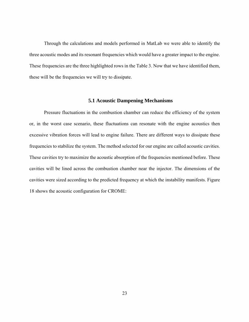
5.1 Acoustic Dampening Mechanisms
Pressure fluctuations in the combustion chamber can reduce the efficiency of the system
or, in the worst case scenario, these fluctuations can resonate with the engine acoustics then
excessive vibration forces will lead to engine failure. There are different ways to dissipate these
frequencies to stabilize the system. The method selected for our engine are called acoustic cavities.
These cavities try to maximize the acoustic absorption of the frequencies mentioned before. These
cavities will be lined across the combustion chamber near the injector. The dimensions of the
cavities were sized according to the predicted frequency at which the instability manifests. Figure
18 shows the acoustic configuration for CROME:
24
Figure 18 Acoustic Absorber Configuration
17 equally spaced cavity ports will be used for CROME. These resonators were chosen
because they were easy to integrate to our system and can be “tunable” by adding a screw to vary
the length by changing the cavity volume.

25
Chapter 6: CROME Design Analysis
To have a more accurate analysis of the system, each major component was studied
separately. The analysis was performed this way, because each component will experience
different loading conditions. Finite Element Analysis (FEA) was done to verify structural and
thermal integrity of the engine. In order to complete FEA, the requirements for each component
were defined and a safety factor of 1.5 was implemented based on the yield strength of the material.
After the analysis, the components should not experience stresses which exceed the yield strength
of the material and must maintain the 1.5 safety factor. Each model concept was developed with
Altair Hypermesh. The objective was to find areas of high stress and then modify the design if
necessary.
6.1 Thrust Chamber
The thrust chamber may be the most recognizable part of a rocket engine. Almost all rocket
engines use a cylindrical design because they provide less cooling requirements and encounter less
mechanical stress due to smaller surface area. This is where the propellants mix and combustion
takes place. The chamber must follow a converging-diverging profile with a bell nozzle that can
produce 500 lbf of thrust. The design must have provision for thermocouples that will be placed
along the axial and radial directions of the thrust chamber focusing attention on the throat, where
the heat flux is at its highest. Also, it must have provisions for static and dynamic pressure
transducers to measure the pressure inside the chamber. Upon testing the thrust chamber will choke
fluid flow at the throat (𝐴𝑡 < 𝐴∗). If this does not occur then it will be considered a failure. The
interface to the injector will be provided for interchangeability of components. Combustion
chamber must be functional for a pressure range of 0 to 235 psi where 235 psi is the maximum
operating pressure and a maximum allowable pressure of 700 psi. A factor of safety of 1.5 to yield

26
must be met for the maximum allowable pressure induced stresses. Due to the high and cryogenic
temperatures, the material used for the chamber will be Inconel 718 and must withstand the stresses
induced by chamber pressures and thermal stresses. From a melting standpoint, it must not be
heated to or above its melting point during combustion of propellants.
To find the nozzle profile, the thermodynamic properties of our propellants were found
using NASA Chemical Equilibrium with Application (CEA) software. This was necessary in order
to find the diameter of the thrust using the following equation:
𝑪𝒇 = √𝟐 𝒌𝟐
𝒌−𝟏(
𝟐
𝒌+𝟏)
𝒌+𝟏
𝒌−𝟏[𝟏 − (
𝑷𝒆
𝑷𝒄)
𝒌−𝟏
𝒌] + (
𝑷𝒆−𝑷𝒂
𝑷𝒄) 𝝐 = 𝟏. 𝟑 Equation 3
Where:
Cf: Thrust coefficient, the increase of thrust provided by the gas expansion through the nozzle
k: specific heat ratio
Pc: chamber pressure
Pa: atmospheric pressure
Pe: pressure at the exit
The next step was to find the diameter of the throat using the following equation:
𝑨𝒕 = 𝑭𝒕
𝑷𝒄 𝑪𝒇=
500 𝑙𝑏𝑓
235 𝑝𝑠𝑖 ∗1.3= 1.68 𝑖𝑛2 Equation 4
This yield a diameter of 1.46 in.
Lastly, the characteristic length or L* (the ratio between the volume of the chamber and the area
of the throat was found using the following equation:
𝑳∗ = 𝑽𝒄
𝑨𝒕→ 𝑽𝒄 = 𝟑𝟔 𝒊𝒏𝟑 Equation 5
27
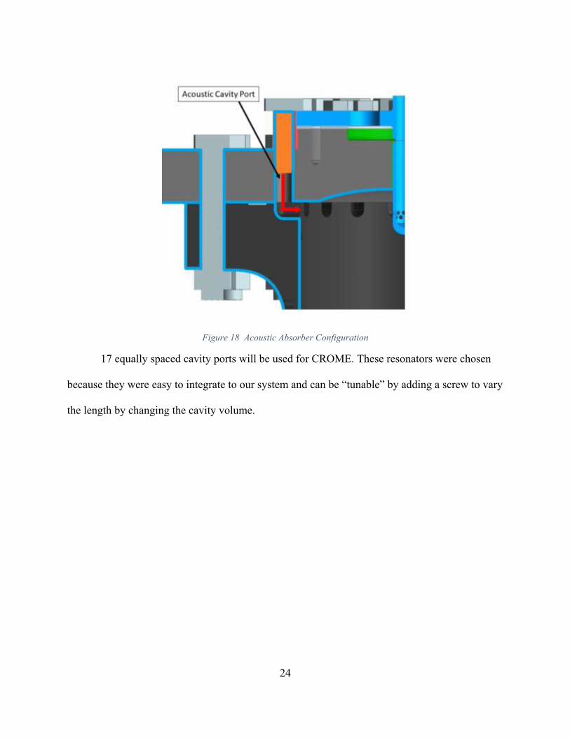
Using these values, the first design of the thrust chamber was designed. Figure 19 shows
the first design of the thrust chamber. The profile of the nozzle was taken from RPA by determining
the thermodynamic properties of our propellants, chamber pressure, and desired thrust. The idea
was to attach the thrust chamber to the structure using 4 bolts and weld the corresponding
thermocouples along the surface of the nozzle. However, this configuration would create major
stress on the attachments and the manufacturing cost would increase significantly due to the
complicity of manufacturing a nozzle. Lastly, preliminary analysis showed that the wall thickness
would not pass the FoS requirement.
Figure 19 Thrust Chamber First Iteration
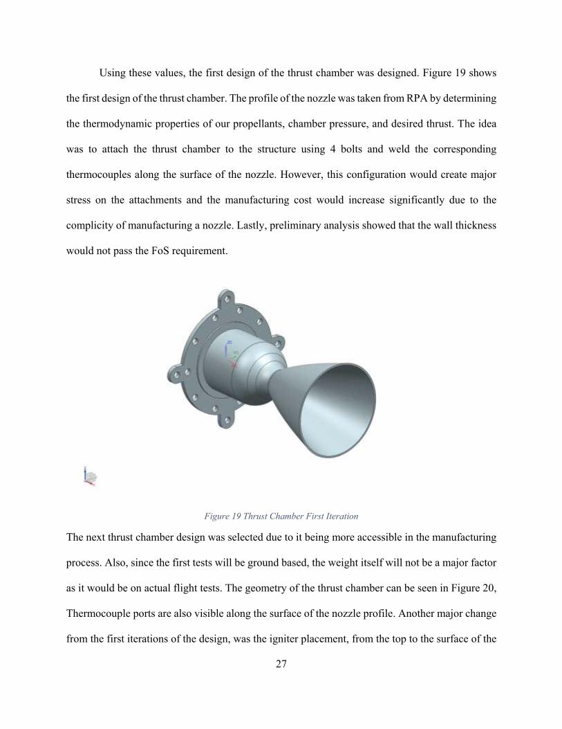
The next thrust chamber design was selected due to it being more accessible in the manufacturing
process. Also, since the first tests will be ground based, the weight itself will not be a major factor
as it would be on actual flight tests. The geometry of the thrust chamber can be seen in Figure 20,
Thermocouple ports are also visible along the surface of the nozzle profile. Another major change
from the first iterations of the design, was the igniter placement, from the top to the surface of the
28
chamber. This will allow more space on top of the engine for the main valves and feed system.
Provisional support will be provided for the igniter assembly.
Figure 20 Last Iteration of Thrust Chamber Geometry
Wall thickness was increased from 0.1 in to 0.25 in after performing a thickness analysis to find
the optimal thickness that would satisfy thrust chamber structural requirements. For this, we found
the vonMisses stress using Equation 5:
𝜎𝑣 = √𝜎ℎ2 + 𝜎𝑙
2 + (𝜎ℎ ∗ 𝜎𝑙) Equation 6
Where:
σh: Hoop stress
σl: Longitudinal stress
To find the Hoop and Longitudinal stress we use the maximum expected Pc and inner diameter of
the chamber. Dividing 11750 psi (Inconel 718 yield strength @ 2000 °F) over the vonMisses stress
29
of 6813 psi, we have a FoS of 1.72, meeting thrust chamber structural requirements (see
Appendix).
The placement of the dynamic pressure transducers
should be such that they should not be damaged
during hot fire testing. Figure 21 shows the
placement of the dynamic pressure transducers that
will be used to validate frequencies.
In order to begin the study of this
component, we found the bolt preloads on the thrust
chamber flange. A required 2500 psi is needed for
the GORE seal to seal according to the
manufacturer. To find the total force needed to seal we use Equation 6:
𝐹𝑐 = (𝐴𝑐 ∗ 𝑃𝑔) + (𝑃𝑐 ∗ 𝐴𝑐𝑐) Equation 7
Where:
Ac: compressed contact area
Pg: required GORE seal pressure
Pc: chamber pressure
Acc: chamber contact
A total preload of 2443 lbf per bolt is required to seal using 14 UNC (3/8)-16 bolts (see Appendix).
We can take advantage of the chamber’s geometry using quarter symmetry to reduce the
domain by a factor of 4. The reduction in analysis domain could mean a finer mesh that can be
used in the reduced analysis domain yielding more accurate results. The reduction in
Figure 21 Dynamic Pressure Transducers
Configuration

30
computational time also plays an important role in the analysis. A mesh was created using
Hypermesh 3D elements with a minimum element size of 0.05 in.
Figure 22 Combustion Chamber Mesh
The following table shows the loads applied to the thrust chamber:
Table 4 Combustion Chamber Loading Conditions
Figure Load Value
Temperature SPC 1700 °F
Quarter-Symmetry SPC N/A
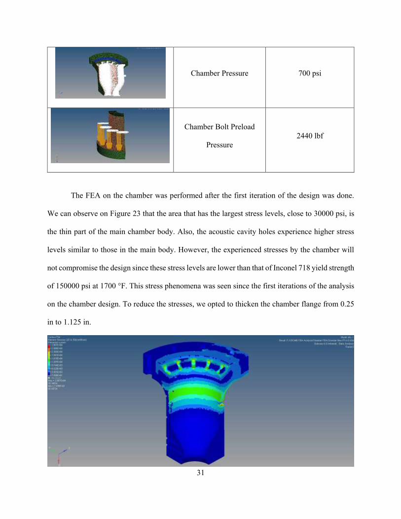
31
Chamber Pressure 700 psi
Chamber Bolt Preload
Pressure
2440 lbf
The FEA on the chamber was performed after the first iteration of the design was done.
We can observe on Figure 23 that the area that has the largest stress levels, close to 30000 psi, is
the thin part of the main chamber body. Also, the acoustic cavity holes experience higher stress
levels similar to those in the main body. However, the experienced stresses by the chamber will
not compromise the design since these stress levels are lower than that of Inconel 718 yield strength
of 150000 psi at 1700 °F. This stress phenomena was seen since the first iterations of the analysis
on the chamber design. To reduce the stresses, we opted to thicken the chamber flange from 0.25
in to 1.125 in.

32
Figure 23 Chamber Stress Contours
6.2 Injector Body
This part of the engine puts the propellants in the combustion chamber, it atomizes,
distributes, and mix the propellants into the appropriate ratio of fuel and oxidizer. The design
determines the maximum achievable combustion efficiency, the heat transfer rated to the
combustion chamber walls, and whether or not low and high frequency combustion instabilities
will occur (Yang, Habiballah, Hulka, & Popp, 2004). No other component of a rocket engine has
greater impact upon engine performance, each percentage point loss in injector combustion
efficiency (c*) means a loss of the same magnitude in overall specific impulse (Isp) (Douglass,
Combs, & Keller, 1975). The first design of the injector body can be seen in Figure 24. This design
has an igniter port before we decided to place the igniter on the chamber.
Figure 24 Injector Body First Iteration
During the 2017 Southwest Emerging Technology Symposium, Mark Klem, chief of the Chemical
Propulsion Systems Branch at NASA Glenn Research Center, reviewed our design and
33
recommended to switch out design from fuel centered to LOX centered, meaning the liquid oxygen
would go through the pintle, and liquid methane through the injector body orifice. The main
concern from the first design was the GORE seal reliability. Figure 25 shows a cross-section of
the fuel centered design:
Figure 25 Injector Body Fuel Centered Design
In a worst-case scenario of having back-flow from the ignited fuel to the manifold, the whole
engine would fail. The new injector body geometry is displayed in Figure 26:
Figure 26 Injector Body Geometry
34
A non-permanent sealed interface will be used for the first stage of testing for mounting of
injector to pintle manifold and thrust chamber meeting gasket requirements. This allows for
interchangeability of components for conditions such as failure, varied condition firing, etc. GORE
seal will be used to maintain the propellant within the thrust chamber and the injector body. The
seal must prevent leaking of propellant into the atmosphere. A film cooling channel must be
provided to avoid melting temperatures. 30% of the fuel flow rate for combustion is going to be
used for cooling (0.5-0.18 lbm/s). The material selected for the injector was Inconel 625 due to its
strength properties discussed before and weldability to other like components. Conventional
machining operating will be used to manufacture the injector body.
The injector must be functional for a pressure range of 70-235 psi where 235 psi is the
maximum operating pressure. A factor of safety of 1.5 to yielding must be met for pressure induced
stresses. No structural failure should occur i.e. plastic deformation, melting, or pressure stress
cracks. The pressure ranges from 75 to 235 psi at full thrust, however, a pressure spike of 700 psi
is expected.
A bolted configuration will be used to interface the injector body to thrust chamber, a
second configuration to interface injector body to the structure, and a third configuration to the
manifold. The interface from injector body to thrust chamber should be such that the injection of
propellants into the combustion chamber is reliable. The bolts used must not pass 90% proof load
and must apply the sufficient pressure to the GORE in order to have a reliable seal. 14 (3/8)-16
bolts will be used to connect the injector body to the thrust chamber. The bolt analysis was
described in section 6.1.
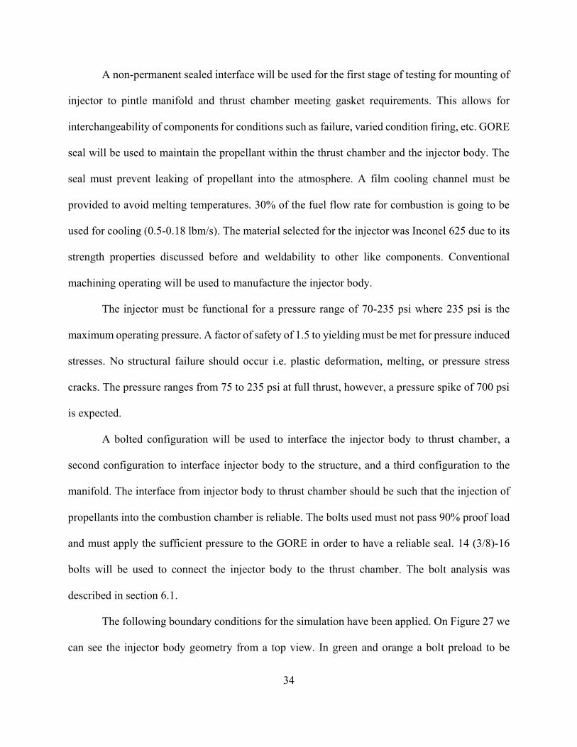
The following boundary conditions for the simulation have been applied. On Figure 27 we
can see the injector body geometry from a top view. In green and orange a bolt preload to be
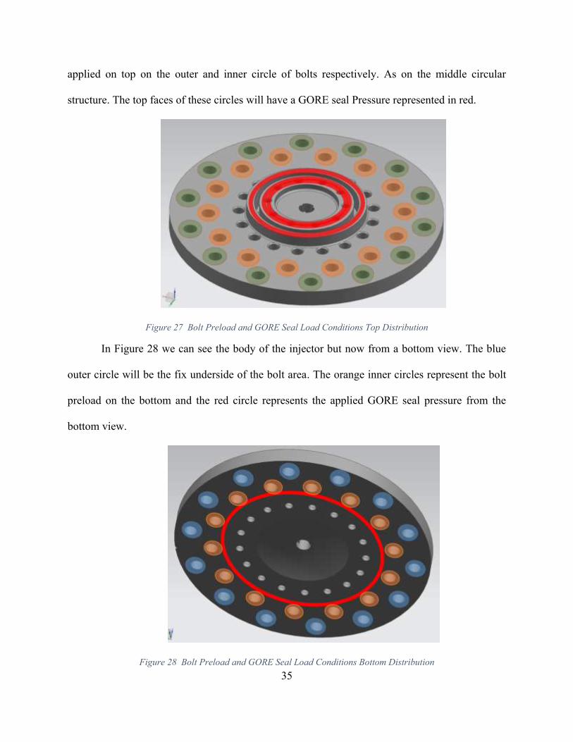
35
applied on top on the outer and inner circle of bolts respectively. As on the middle circular
structure. The top faces of these circles will have a GORE seal Pressure represented in red.
Figure 27 Bolt Preload and GORE Seal Load Conditions Top Distribution
In Figure 28 we can see the body of the injector but now from a bottom view. The blue
outer circle will be the fix underside of the bolt area. The orange inner circles represent the bolt
preload on the bottom and the red circle represents the applied GORE seal pressure from the
bottom view.
Figure 28 Bolt Preload and GORE Seal Load Conditions Bottom Distribution

36
Just like with the chamber geometry, the injector’s geometry can be used with quarter
symmetry to reduce the domain by a factor of 4. The domain reduction means a finer mesh which
will yield more accurate results. The reduction in computational time also plays an important role
in the analysis. A mesh was created using Hypermesh 3D elements with a minimum element size
of 0.01 in.
Figure 29 Injector Body Mesh
A finer mesh was generated around the end of the acoustic cavity holes and bolted
connection to thrust chamber. This was done because, in the first iterations of the analysis, .the
cavity holes and bolted connection to thrust chamber, were the areas where we found higher stress.
After analyzing the stress areas, modifications to the design were made to sustain the stress to
acceptable levels where it would not compromise the design. To reduce the stress on these areas,
we opted to thicken the injector thickness from 0.5 in to 0.875 in.
37
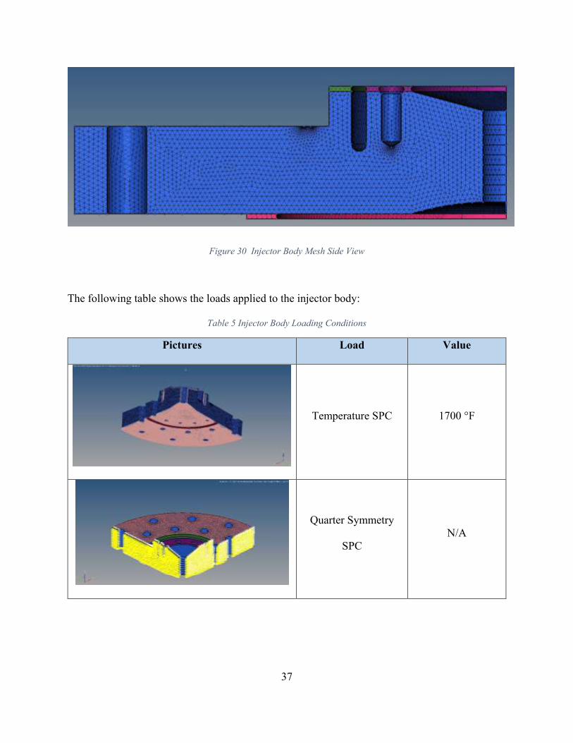
Figure 30 Injector Body Mesh Side View
The following table shows the loads applied to the injector body:
Table 5 Injector Body Loading Conditions
Pictures Load Value
Temperature SPC 1700 °F
Quarter Symmetry
SPC
N/A

38
Outer Bolt Preload 10900 lbf
Chamber Bolt Preload 28500 lbf
Acoustic Cavities 33 psi
Pintle Post Preload 1230 lbf
Chamber Pressure 230 psi

39
Chamber GORE Seal
Pressure
3000 psi
Inner GORE Seal
Pressure
3750 psi
Outer GORE Seal
Pressure
3750 psi
Pintle Pressure 235 psi
Once the setup was completed for the injector body, the model was run to obtain the stress
analysis of the component. The vonMisses stresses were examined to determine if the injector met
the desired structural requirements. The results of the FEA and the values of the vonMisses stresses
experienced by the injector body are presented below.

40
Figure 31 reflects the stresses experienced by the critical parts mentioned above. From the
overall figure we found the vonMisses stress on the outer bolted connection that goes to the
structure and the acoustic cavity holes are the ones that experience a higher stress of 48840 psi
which is less than the Inconel 625 yield strength of 120000 at 1800 °F. The greatest issue we
encountered with the first iterations is that the part was to thin and hence it experienced more than
the allowable stress. We had to modify the part by enlarging its thickness. This modification led
to other ones, i.e. bolts had to be changed in size and the acoustic cavity holes had to change its
dimensions in order to keep the desired dampening.
Figure 31 Injector Body Stress Contours

41
Figure 32 Injector Body Thermal Gradient
In Figure 32 we applied a thermal gradient (2160R-1080R) on injector face, convection on flange,
and cryo-temperatures in cooling manifold. The highest stress is 57570 psi, less than Inconel 625
yield strength of 120000 at 1800 °F. Through this analysis we have tested and proven that the
injector body will be able to safely resist the combustion temperatures without experiencing critical
stresses that would endanger the engine and DEADALUS mission.
42
6.3 Pintle Manifold
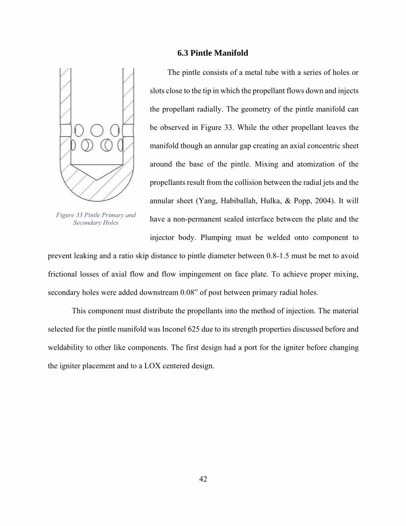
The pintle consists of a metal tube with a series of holes or
slots close to the tip in which the propellant flows down and injects
the propellant radially. The geometry of the pintle manifold can
be observed in Figure 33. While the other propellant leaves the
manifold though an annular gap creating an axial concentric sheet
around the base of the pintle. Mixing and atomization of the
propellants result from the collision between the radial jets and the
annular sheet (Yang, Habiballah, Hulka, & Popp, 2004). It will
have a non-permanent sealed interface between the plate and the
injector body. Plumping must be welded onto component to
prevent leaking and a ratio skip distance to pintle diameter between 0.8-1.5 must be met to avoid
frictional losses of axial flow and flow impingement on face plate. To achieve proper mixing,
secondary holes were added downstream 0.08” of post between primary radial holes.
This component must distribute the propellants into the method of injection. The material
selected for the pintle manifold was Inconel 625 due to its strength properties discussed before and
weldability to other like components. The first design had a port for the igniter before changing
the igniter placement and to a LOX centered design.
Figure 33 Pintle Primary and
Secondary Holes
43
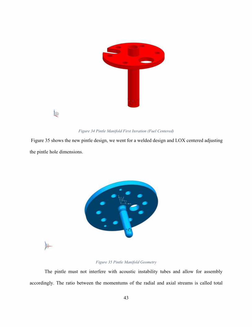
Figure 34 Pintle Manifold First Iteration (Fuel Centered)
Figure 35 shows the new pintle design, we went for a welded design and LOX centered adjusting
the pintle hole dimensions.
Figure 35 Pintle Manifold Geometry
The pintle must not interfere with acoustic instability tubes and allow for assembly
accordingly. The ratio between the momentums of the radial and axial streams is called total
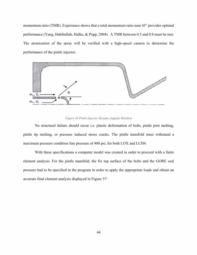
44
momentum ratio (TMR). Experience shows that a total momentum ratio near 45° provides optimal
performance (Yang, Habiballah, Hulka, & Popp, 2004). A TMR between 0.5 and 0.8 must be met.
The atomization of the spray will be verified with a high-speed camera to determine the
performance of the pintle injector.
Figure 36 Pintle Injector Streams Angular Relation
No structural failure should occur i.e. plastic deformation of bolts, pintle post melting,
pintle tip melting, or pressure induced stress cracks. The pintle manifold must withstand a
maximum pressure condition line pressure of 400 psi, for both LOX and LCH4.
With these specifications a computer model was created in order to proceed with a finite
element analysis. For the pintle manifold, the fix top surface of the bolts and the GORE seal
pressure had to be specified in the program in order to apply the appropriate loads and obtain an
accurate final element analysis displayed in Figure 37:
45
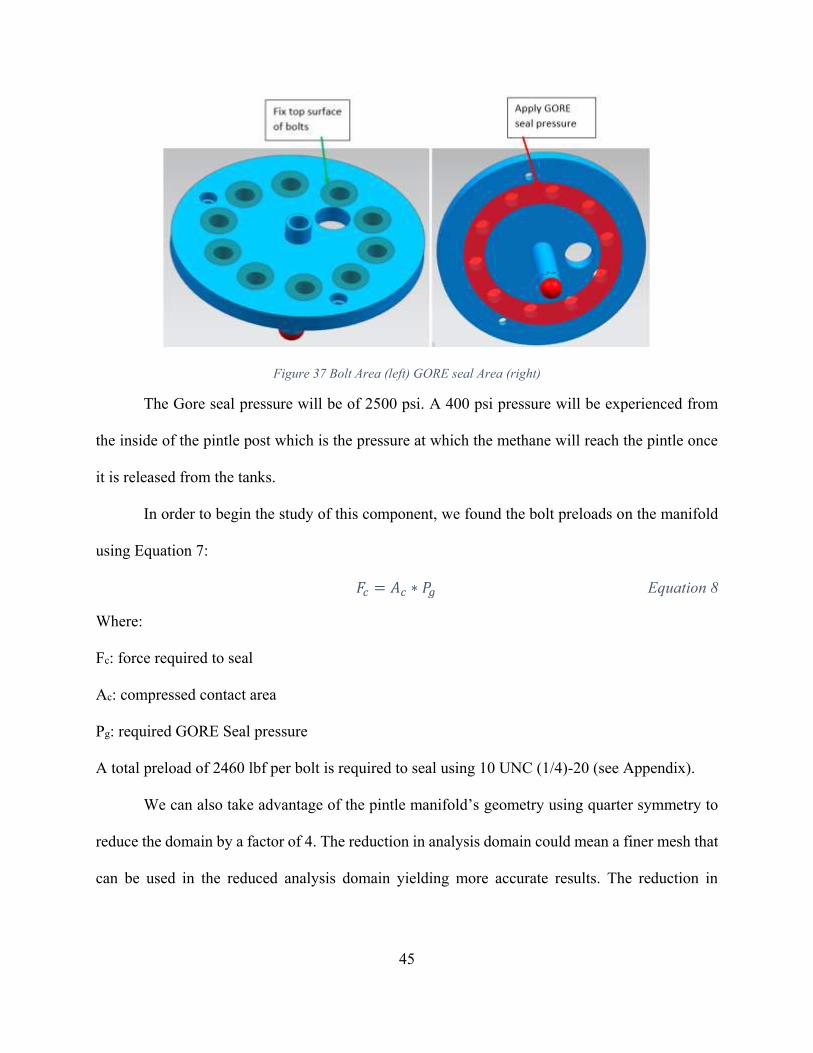
Figure 37 Bolt Area (left) GORE seal Area (right)
The Gore seal pressure will be of 2500 psi. A 400 psi pressure will be experienced from
the inside of the pintle post which is the pressure at which the methane will reach the pintle once
it is released from the tanks.
In order to begin the study of this component, we found the bolt preloads on the manifold
using Equation 7:
𝐹𝑐 = 𝐴𝑐 ∗ 𝑃𝑔 Equation 8
Where:
Fc: force required to seal
Ac: compressed contact area
Pg: required GORE Seal pressure
A total preload of 2460 lbf per bolt is required to seal using 10 UNC (1/4)-20 (see Appendix).
We can also take advantage of the pintle manifold’s geometry using quarter symmetry to
reduce the domain by a factor of 4. The reduction in analysis domain could mean a finer mesh that
can be used in the reduced analysis domain yielding more accurate results. The reduction in

46
computational time also plays an important role in the analysis. A mesh was created using
Hypermesh 3D elements with a minimum element size of 0.02 in.
Figure 38 Pintle Manifold Mesh
The following table shows the loads applied to the pintle manifold:
Table 6 Pintle Manifold Loading Conditions
Pictures Load Value
Quarter Symmetry SPC N/A
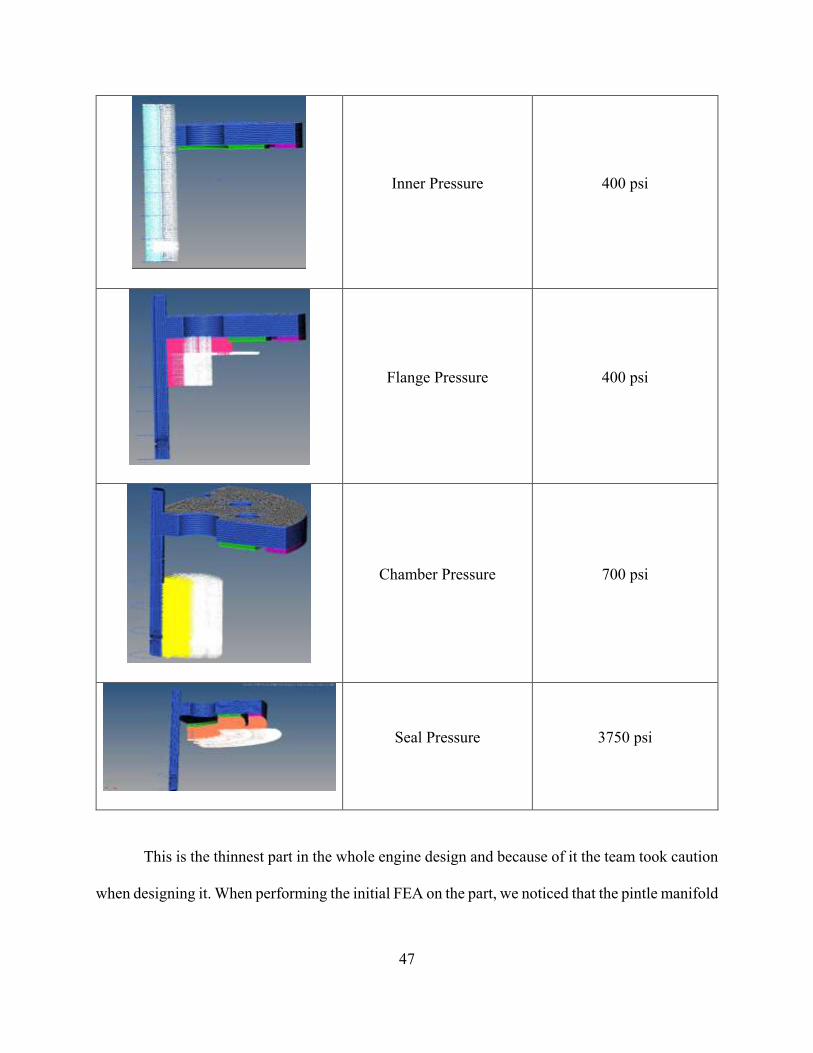
47
Inner Pressure 400 psi
Flange Pressure 400 psi
Chamber Pressure 700 psi
Seal Pressure 3750 psi
This is the thinnest part in the whole engine design and because of it the team took caution
when designing it. When performing the initial FEA on the part, we noticed that the pintle manifold
48
experienced high stress levels that could compromise the design. Because of this, we changed the
area of the holes to try to lower the high stress level at this area.
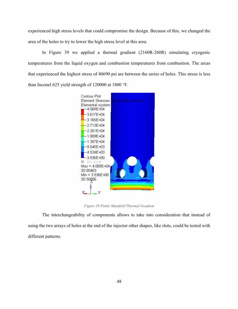
In Figure 39 we applied a thermal gradient (2160R-260R) simulating cryogenic
temperatures from the liquid oxygen and combustion temperatures from combustion. The areas
that experienced the highest stress of 40690 psi are between the series of holes. This stress is less
than Inconel 625 yield strength of 120000 at 1800 °F.
Figure 39 Pintle Manifold Thermal Gradient
The interchangeability of components allows to take into consideration that instead of
using the two arrays of holes at the end of the injector other shapes, like slots, could be tested with
different patterns.
49
Chapter 7: Valves & Instrumentation
Different valve types were considered for this engine. Precise control of the propellant
going into the engine is crucial for the operation of CROME. Because of this, throttle valves
selection is crucial for the succes of the mission. Two main valves will be controlling the flow
from 125 to 500 lbf to vary the thrust for vehicle dynamic control. Following advice from JSC,
and setting the requirement needed for each throttle level, we decided to use ball valves because
they only require a quarter turn to be completely opened or closed. Although ball valves have poor
throttling characteristics because in a throttling position, the partially exposed seat may be prone
to erosion as a result of high velocity flows, we decided to use a ball valve with a v-shaped port.
This allows a better control through the position of the valve. The minimum required flow
coefficient (Cv) was obtained from the valve requirements. This indicated valve performance, the
larger the Cv, the smaller pressure drop caused by the valve. The equation for Cv is as follows:
𝐶𝑣 = 𝑄√𝑆𝐺
𝛥𝑃𝑉 Equation 9
Wehre:
Q: volumetric flow ratethrough the valve (Gal/min)
SG: specific gravity of the fluid
ΔPv: pressure drop across the valve
Based on the valve requirements, it was determined that the valve would require a minimum Cv of
15.
50
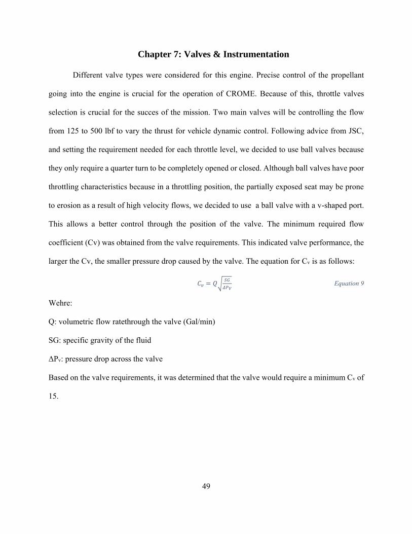
Figure 40 Habonim Ball Valves (left) 60° v-port (right)
The valves were manufactured by Habonim Induatrial Valve & Actuators and provided a 60° v-
port ball valve which met the control and pressure drop requirements for our system. An actuator
was also selected based on the specification of the valves as wel as CROME’s control
requirements. The maximum valve reaction time from fully closed to fully open is 0.5 s. Based on
these requirements a DC motor was selected as the actuator for the valves combined with a 71:1
gear ratio gearbox. The minimum operating temperature for the gear box is -22 °F and since we
operate at cryogenic temperatures, a connector was designed to act as a thermal standoff and also
transfer the required torque from the gearbox to the valve. Computational analysis was done to
ensure the integrity of the connector. The material selected for this connector was titanium alloy
Ti-64 due to its high strength and low thermal conductivity. Also, this connector will be 3D printed
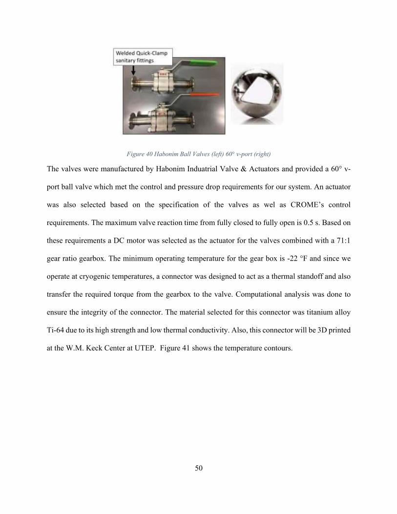
at the W.M. Keck Center at UTEP. Figure 41 shows the temperature contours.
51
Figure 41 Connector & Thermal Contour
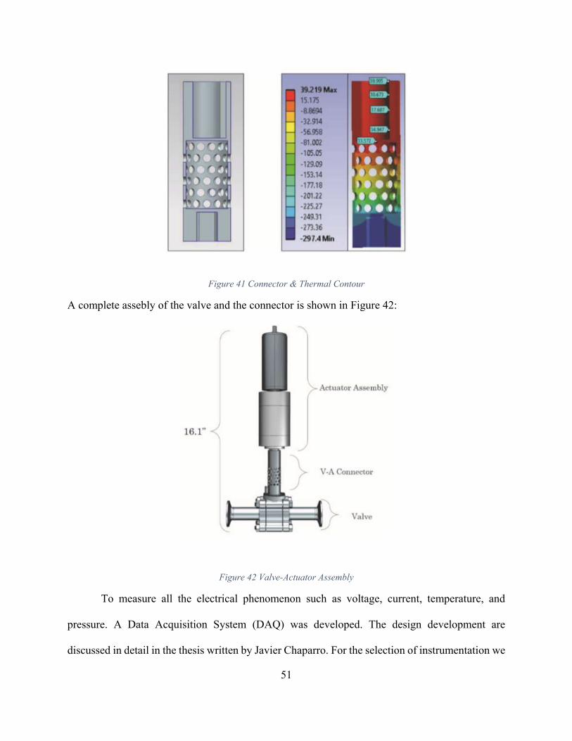
A complete assebly of the valve and the connector is shown in Figure 42:
Figure 42 Valve-Actuator Assembly
To measure all the electrical phenomenon such as voltage, current, temperature, and
pressure. A Data Acquisition System (DAQ) was developed. The design development are
discussed in detail in the thesis written by Javier Chaparro. For the selection of instrumentation we

52
closely worked with the DAQ system team in order to comply with the voltage requierements.
Nonetheless, the DAQ system is capable to support more than the required instrumentation in case
the team ever needs to include other data parameters. All the data will be recorded using LabView
Software. One of the main reasons the team decided to use LabView is that with its current
capibilities we are able to measure real time data like pressure, temperature, etc. Table 5 shows the
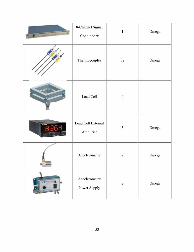
rest of the valves and instrumention that will be used:
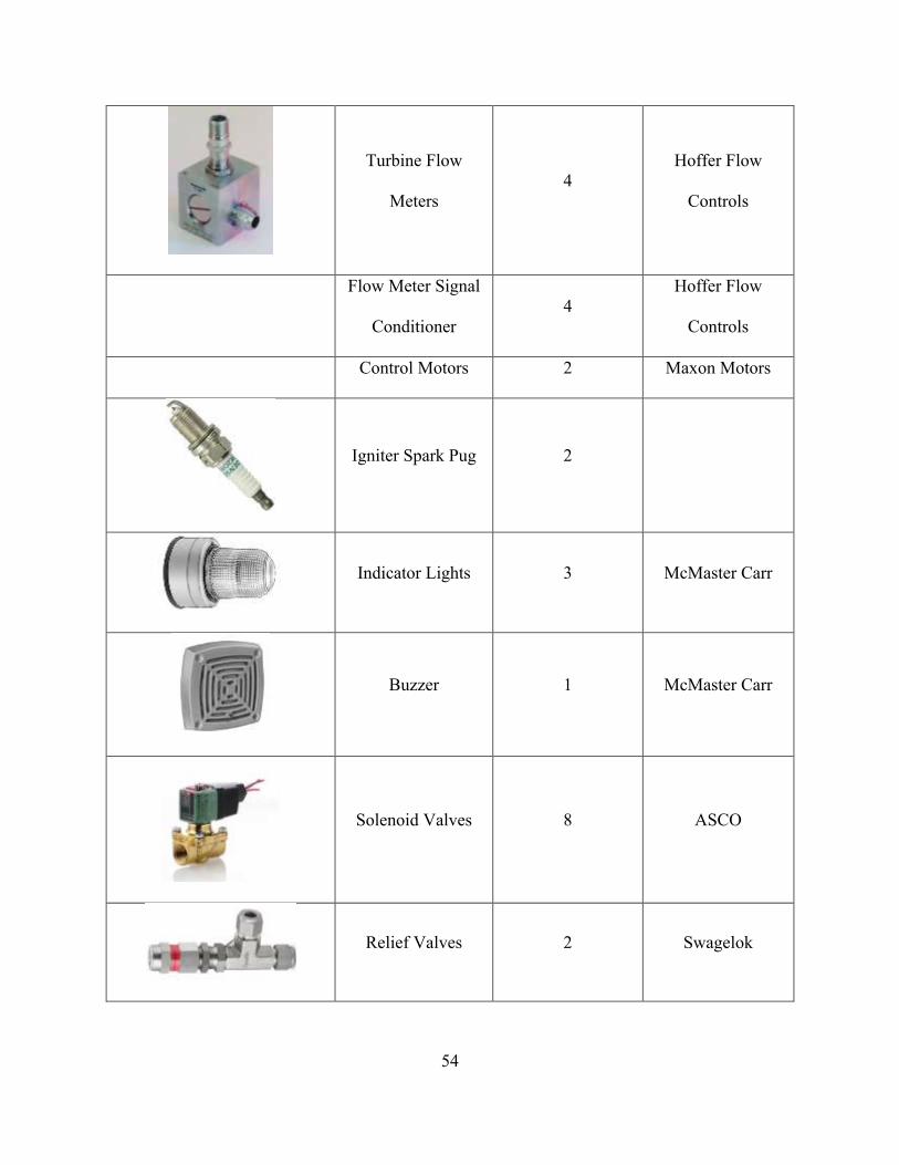
Table 7 DEADALUS Instrumentation
Picture Part
Number
Required
Vendor
Static Pressure
Transducer
16 Omega
Pressure
Transducer
External Amplifier
16 Omega
f
Dynamic Pressure
Transducer
2 PCB Piezotronics
53
8-Channel Signal
Conditioner
1 Omega
Thermocouples 32 Omega
Load Cell 4
Load Cell External
Amplifier
3 Omega
Accelerometer 2 Omega
Accelerometer
Power Supply
2 Omega
54
Turbine Flow
Meters
4
Hoffer Flow
Controls
Flow Meter Signal
Conditioner
4
Hoffer Flow
Controls
Control Motors 2 Maxon Motors
Igniter Spark Pug 2
Indicator Lights 3 McMaster Carr
Buzzer 1 McMaster Carr
Solenoid Valves 8 ASCO
Relief Valves 2 Swagelok

55
Check Valves 4 Swagelok
Hand Valves 4 Swagelok
Line Connections Swagelok
Pressure Gauge 2 Omega
Filter 4 Norman Filters
Pressure Regulators 8 Airgas

56
Chapter 8: Future Work
The CROME and DEADALUS has been in production since 2015. At the beginning of the
project the vehicle requirements were defined per the purpose of the mission. Once all the
requirements were set, the the design process started. The engine parts were built in CAD models
and FEA were performed on them. Various iterations were done until an optimal design was
achieved which met the previously established requirements. During this process the blueprints
for the engine were constantly changing to meet the requirements of the project. A Geometric
Dimensioning and Tolerancing (GD&T) format was used throughout the project to keep track of
all the drawing under the same format. Once the FEA returned optimal results and the blueprints
for the parts were finished, the design was approved.
After this, the drawings were sent to a local company in El Paso, TX for a quote to build
it. Unfortunately, the local company had to send some of the parts to another company since due
to the material and the difficulty degree of the parts it was not possible to make them so it was
given to another manufacturer. This added lag time to the overall project. Once it was finished and
built it was sent back to the cSETR and all of this process happened while this thesis was in
development.
The hot fire test procedure is being written
and will be submitted for approval. It is expected
that for the year 2018 the actual hot fire tests will be
conducted now that the Technology Research and
Innovation Accelerration Park (tRIAc) has been
completed. Water test setup procedure has been
approved and it is ready for actual testing since the Figure 43 Rendering of cSETR's tRIAc
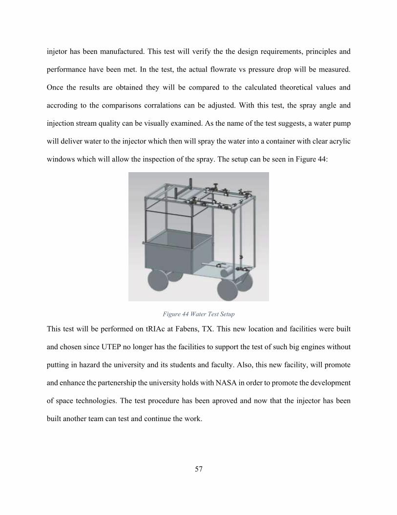
57
injetor has been manufactured. This test will verify the the design requirements, principles and
performance have been met. In the test, the actual flowrate vs pressure drop will be measured.
Once the results are obtained they will be compared to the calculated theoretical values and
accroding to the comparisons corralations can be adjusted. With this test, the spray angle and
injection stream quality can be visually examined. As the name of the test suggests, a water pump
will deliver water to the injector which then will spray the water into a container with clear acrylic
windows which will allow the inspection of the spray. The setup can be seen in Figure 44:
Figure 44 Water Test Setup
This test will be performed on tRIAc at Fabens, TX. This new location and facilities were built
and chosen since UTEP no longer has the facilities to support the test of such big engines without
putting in hazard the university and its students and faculty. Also, this new facility, will promote
and enhance the partenership the university holds with NASA in order to promote the development
of space technologies. The test procedure has been aproved and now that the injector has been
built another team can test and continue the work.

58
Chapter 9: Conclusion
This project was based on NASA’s Morpheus vehicle in order to design and create the
CROME engine for the DEADALUS vehicle. The requirements for this engine was the usage of
LO2-LCH4 propellants and a thrust of 500 lbf. The engine was fully assembled during the
completion of this document. The process of design and analysis of its components were described
in the above sections of this thesis. The objective of this project is to successfully perform a hot
fire test at the tRIAC test facility. Aerospace industry has been growing rapidly in the past decades,
the study of LOX/LCH4 capabilities will help future aerospace endeavors more affordable.

59
References
Atyam, D. M., & Hguyen, N. H. (2015). Designing and Testing Liquid Engine for Additive
Manufacturing. Orlando, FL: 51st AIAA/SAE/ASEE Joint Propulsion Conference.
Brown, C. D. (1996). Spacecraft Propulsion. Washington D.C.: American Institute of Aeronautics
and Astronautics.
Budynas, R. G., & Nisbett, K. J. (2003). Shingley's Mehcanical Engineering Design. New York,
NY: McGraw-Hill.
Candelaria, J. (2017). Theoretical Acoustic Absorber Design Approach for LOX/LCH4 Pintle
Injector Rocket Engines. El Paso, TX: UTEP Center for Space Exploration and
Techonology Research.
Douglass, H. W., Combs, L. P., & Keller, R. B. (1975). Liquid Rocket Engine Combustion
Stabiliztion Devices. Washington, D.C.: National Aeronautics and Space Administration.
Dressler, G. A., & Bauer, M. J. (2000). TRW Pintle Engine Heritage and Performance
Characteristics. 36th AIAA/ASME/SAE/ASEE Joint Propulsion Conference and Exhibit.
Gill, G. S., Nurick, W. H., Keller, R. B., & Douglass, H. W. (1976). Liquid Rocket Engine
Injectors. Cleveland, OH: National Aeronautics and Space Administration.
Hart, J., & Devolites, J. (2014). Morpheus Vertical Test Bed Flight Testing. Big Sky , MT: IEEE
Aerospace Conference.
Huzel, D. K., & Huang, D. H. (1992). Modern Engineering for Design of Liquid-Propellant Rocket
Engines. Washington D.C.: American Institue of Aeronautics and Astronautics.
Lopez, I. (2017). Design of a 2000 lbf LOX/LCH4 Throttleable Rocket Engine for a Vertical
Lander. El Paso, TX: UTEP Center for Space Exploration and Techonology Research.
Sutton, G. (2001). Rocket Propulsion Elements. New York: Wiley.
60
Sutton, G. P., & Biblarz, O. (2010). Rocket Propulsion Elements. Hoboken, NJ: John Wiley &
Sons.
Trillo, J. E. (2016). Design of a 500 lbf Liquid Oxygen and Liquid Methane Rocket Engine for
Suborbital Flight. El Paso, TX: UTEP Center for Space Exploration and Technology
Research.
Yang, V., Habiballah, M., Hulka, J., & Popp, M. (2004). Liquid Rocket Thrust Chambers: Aspects
of Modeling, Analysis, and Design. Reston, VA: American Institue of Aeronautics and
Astronomics.

61
Appendix
A1 Thrust chamber wall thickness analysis
𝜎ℎ =𝑃𝑐(𝑑𝑖 + 𝑡)
𝑡 ∗ 2=
700(3.5 + 0.25)
0.25 ∗ 2= 5250 𝑝𝑠𝑖
Where:
σh: Hoop stress
Pc: maximum chamber pressure
di: inner diameter of the chamber
t: wall thickness
𝜎𝑙 =𝑃𝑐 ∗ 𝑑𝑖
𝜎ℎ ∗ 4=
700 ∗ 3.5
5250 ∗ 4= 2450 𝑝𝑠𝑖
Where:
σl: longitudinal stress
Pc: maximum chamber pressure
di: inner diameter of the chamber
𝜎𝑣 = √𝜎ℎ2 + 𝜎𝑙
2 + (𝜎ℎ ∗ 𝜎𝑙) = √52502 + 24502 + (5250 ∗ 2450) = 6813.77 𝑝𝑠𝑖
Where:
σv: vonMisses stress
σh: Hoop stress
σl: longitudinal stress
𝑆. 𝐹. =𝑆𝑦
𝜎𝑣=
11750
6813.77= 1.72
Where:
S.F.: Safety Factor

62
Sy: Inconel 718 yield strength @ 2000 °F
σv: vonMisses stress
A2 Injector Body/Chamber Flange Bolt Analysis
𝑃 = 𝑃𝑐 ∗ 𝐴𝑐𝑐 = 700 ∗ 15.6 = 10920 𝑝𝑠𝑖
Where:
P: total pressure
Pc: maximum chamber pressure
Acc: chamber contact area
𝐴𝑐 = 𝑘1 ∗ 𝐴𝑠 = 1.2 ∗ 5.86 = 7.03 𝑖𝑛2
Where:
Ac: compressed contact area
k1: compressibility factor given by manufacturer
As: uncompressed contact area of the GORE seal
𝐹𝑐 = (𝐴𝑐 ∗ 𝑃𝑔) + 𝑃 = (7.03 ∗ 2500) + 10920 = 28503 𝑝𝑠𝑖
Where:
Fc: total force needed to seal
Ac: compressed contact area
Thickness of wall (in) Hoop Stress (psi) Longitudinal Stress (psi) Vonmises Stress (psi) S.F0.14 9100 4375 11906.43209 0.986861548
0.15 8516.666667 4083.333333 11134.79282 1.055250887
0.16 8006.25 3828.125 10459.61308 1.123368513
0.17 7555.882353 3602.941176 9863.870584 1.191215953
0.18 7155.555556 3402.777778 9334.325757 1.258794722
0.19 6797.368421 3223.684211 8860.526316 1.326106326
0.2 6475 3062.5 8434.11043 1.393152259
0.21 6183.333333 2916.666667 8048.309001 1.459934006
0.22 5918.181818 2784.090909 7697.583674 1.52645304
0.23 5676.086957 2663.043478 7377.359287 1.592710825
0.24 5454.166667 2552.083333 7083.823206 1.658708816
0.25 5250 2450 6813.772817 1.724448454
0.26 5061.538462 2355.769231 6564.498216 1.789931174
0.27 4887.037037 2268.518519 6333.690969 1.855158399
0.28 4725 2187.5 6119.372415 1.920131544
0.29 4574.137931 2112.068966 5919.836813 1.98485201
63
Pg: required GORE seal pressure
P: total pressure
𝐹𝑠 =𝐹𝑐
𝑁=
28503
14= 2035.93 𝑙𝑏𝑓
Where:
Fs: force required per bolt to seal
Fc: total force needed to seal
N: number of bolts
𝐹𝑖 = 𝐹𝑠 ∗ 𝑛𝑠 = 2034.93 ∗ 1.2 = 2443.11 𝑙𝑏𝑓
Where:
Fi: preload on the bolts
Fs: force required per bolt to seal
ns: sealing factor (ratio between the preload on the bolts and the required force per bolt to seal)
A3 Manifold Cap Bolt Analysis
𝐴𝑐 = 𝑘1 ∗ 𝐴𝑠 = 1.2 ∗ 5.47 = 6.56 𝑖𝑛2
Where:
Ac: compressed contact area
k1: compressibility factor given by manufacturer
As: normal contact area (uncompressed)
𝐹𝑐 = 𝐴𝑐 ∗ 𝑃𝑔 = 6.56 ∗ 2500 = 16401 𝑙𝑏𝑓
Where:
Fc: force required to seal
Ac: compressed contact area
Pg: required GORE seal pressure

64
𝐹𝑠 =𝐹𝑐
𝑁=
16401
10= 1640.1 𝑙𝑏𝑓
Where:
Fs: required force per bolt to seal
Fc: total force needed to seal
N: number of bolts
𝐹𝑖 = 𝐹𝑠 ∗ 𝑛𝑠 = 1640.1 ∗ 1.2 = 2460.15 𝑙𝑏𝑓
Where:
Fi: preload on the bolts
Fs: required force per bolt to seal
ns: sealing factor (ratio between the preload on the bolts and the required force per bolt to seal)

65
Vita
Daniel Vargas Franco obtained his Bachelor of Science degree in Mechanical Engineering
from the University of Texas at El Paso in the spring of 2015. He started working in the cSETR in
fall 2014 and after his undergraduate studies, he pursued his Master’s degree in Mechanical
Engineering to continue his research in LOX/LCH4 technologies. During his graduate studies, he
was selected as a Pathways Intern at NASA Kennedy Space Center to work with the Environmental
and Life Support Systems branch developing ground support equipment for Space Launch System
(SLS) and the Orion spacecraft.
Contact Information: [email protected]
This thesis was typed by Daniel Vargas Franco