Preliminary Description of the Environmental Data Challenge for DoD M&S

www.recom-power.com REV.: 0/2021 P-1
REH-3.31.8-EVM-1
Evaluation Module
• Evaluation platform for REH-3.31.8 energy harvester module
• Supports rechargeable Li-Ion battery or supercapacitor as energy storage
• Backup coin cell battery holder footprint and input for uninterruptable operation
• Easy setup and evaluation
Features
Evaluation Module
DescriptionThe REH-3.31.8-EVM-1 allows a quick evaluation of the REH-3.31.8 energy harvester module. It contains all the necessary easy-plug-in connectors to connect the energy source, energy storage element, twin output voltages and an external backup battery (if used). The PCB footprint includes pads for a space-saving CR2032 battery holder to serve as an on-board backup battery, if required. If a primary cell back-up battery (1.5VDC to 4.5VDC) is fitted, the REH-Module will automatically switch over to the back-up supply if the energy harvesting input fails to maintain an uninterrupted output.
With the REH-3.31.8-EVM-1 evaluation board, it is possible to configure all of the features of the REH-3.31.8 module such as selection of the type of the storage element (rechargeable battery or supercapacitor), set the backup battery switch-over threshold voltage and to independently enable either or both outputs. All input and output signals of the module are easily accessible for test probes.
Quick Start Guide
Warning: Do not operate the harvester without a storage element (supercapacitor or battery) attached unless you have a stable source of energy on the PV input. In that case the on-board capacity of 3 x 47uF (C1, C2, C3) is sufficient for safe operation.
1. Set storage element type: -populate 0Ω resistor R13 for rechargeable 4.2VDC Li-Ion battery (default) -remove R13 and populate 0Ω resistor R12 for 5VDC supercapacitor
2. Connect selected storage element to P2. Observe correct polarity! Important: Do not plug in the PV input before the storage element is connected. The storage element can be pre-charged for a faster start-up. The voltage cannot exceed 4.5VDC.
3. Backup battery: -if not used, populate R2 and R10 with 0Ω resistors and leave R1 open (default) -if a battery backup is used, remove R2 and R10 and populate R1 and R2 with resistor values from the graph below based on the desired minimum battery backup voltage. For example, a 3VDC lithium coin cell has a minimum voltage of 2.2VDC. Fit either an external battery to P3 or a coin cell holder for an on-board solution (e.g. DigiKey BK-915-CT-ND).
4. Connect energy harvesting source (PV panel, etc.) to the PV connector. Observe the correct polarity! Maximum open voltage of the PV input shall not exceed 5VDC. Any DC source up to 5VDC can be used on this input if a quick charge of the storage element is needed (for example, USB or bench power supply).
Selection GuidePartNumber
Input VoltageRange (1)
[VDC]
Output Voltage 1
[VDC]
OutputCurrent 1 max.
[mA]
Output Voltage 2
[VDC]
OutputCurrent 2 max.
[mA]
REH-3.31.8-EVM-1 0.05 - 5 3.3 80 1.8 20
Notes: Note1: Cold start operation from 0.38VDC
Prelim
inary

www.recom-power.com REV.: 0/2021 P-2
Evaluation ModuleSpecifications (measured @ Ta= 25°C, full load and after warm-up unless otherwise stated)
REH-3.31.8-EVM-1
Component Placement
+
-
GND LO LO LO
P3P2
U1
SELHI
CFG_0
ENERY HARVESTER
CGF_1 MPP_0MPP_1HIHI HI
EN_HV EN_LVHI HIHI
P1PV P4
P5 GND
GND
VOUT_HV
VOUT_LV
BT1CR2032
GND
GND
GND
VBACK
UP
VSTO
RAGE
LO LO LO LO
R12
R13
R15
R14
R17
R16
R19
R18
R8
R4
VOUT_
READY
SHDN
MPP
_CHEC
K
EN_H
V
EN_LV
VBOOST
VREF
R5 R6
R3R9
R11
C1 C2 C3
R2 R1R10
C4C5
R7
R21
R20
R23
R22
R25
R24
5. EN_HV/EN_LV enable: -populate 0Ω resistors R22 and R24 to VREF to permanently enable the outputs (default) -to disable the high voltage output, remove R22 and populate 0Ω resistor R23. -to disable the low voltage output, remove R24 and populate 0Ω resistor R25. Do not solder or remove the resistors during operation! -to allow external control of the HV or LV output, replace R22 and/or R24 with 1MΩ resistors and use an open-collector control signal (OVDC = disabled, open or Vref = enabled) Note the output voltages will not be active (internally disabled) until the voltage on storage element exceeds the minimum storage device threshold levels (3.7VDC or 3.9VDC)
6. For disassembly, always disconnect the PV source and disable the outputs before removing the storage element.
Example:To set up VBACKUP at ~2.2VDCR1= 301kΩ R2= 100kΩ
0 1 2 3 4 50.5 1.5 2.5 3.5 4.5
450
350
400
150
200
250
300
50
0
100
Back
up B
atte
ry F
eedb
ack
Resi
stor
[kΩ
]
Minimum Battery Backup Voltage [VDC]
R1R2
Minimal VBACKUP Battery Voltage vs. FBVBACKUP resistorThe calculated value for trim resistor in below example are according to standard E96 value; therefore, the specified voltage may slightly vary.
Prelim
inary
www.recom-power.com REV.: 0/2021 P-3
Evaluation ModuleSpecifications (measured @ Ta= 25°C, full load and after warm-up unless otherwise stated)
REH-3.31.8-EVM-1
VBACKUP
PV
COLDSTART
FB_VBKP_1
FB_VBKP_2
VSTORAGE
LVOUTLVOUT
GND
GND
GND
GND
GND GND GNDGND
GND
VREF
GND
HVOUTHVOUT
FB_HV
VREF VREF
MPP_1
MPP_0
DISCHARGE
READY
VBOOST
CHARGE
GND
SEL
CFG_1
CFG_0
VREF
VREF
BT1
GND
GND
GND
GND
GND
GND
EN_LVEN_HV
VREF
GND
GND
1-2
R20
R18
R21
R11
R9
R6
R5
R4
R12
R16
R14
R13
R17
R22
R24
R23
R25
R15
R3
D3
D2
A1
A4 E3 U1
B4
C4
A2
C1 C2
R2
0R
R1
R10
C3P2
E5
B5
C5
C4R7
R8
P5
P4
A5
B3
D1
C2
B1
A3
E1
E2
E3
D5 C5 C3 C1 B2
D4
R19
3-4
EN_L
V
EN_H
V
MPP
_CHE
CK
MPP_CHECK
VOUT_READYSHDN
VBOO
ST
VBOOST
VBAC
KPUP
SHDN
VOUT
_REA
DY
1-2
3-4
1-2
3-4
1-2
3-4
1-2
3-4
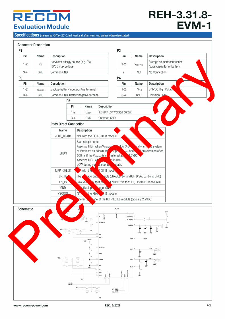
Schematic
Pin Name Description
1-2 PVHarvester energy source (e.g. PV); 5VDC max voltage
3-4 GND Common GND
Pin Name Description
1-2 VBACKUP Backup battery input positive terminal
3-4 GND Common GND, battery negative terminal
Pin Name Description
1-2 LVOUT 1.8VDC Low Voltage output
3-4 GND Common GND
Pin Name Description
1-2 VSTORAGEStorage element connection (supercapacitor or battery)
2 NC No Connection
Pin Name Description
1-2 HVOUT 3.3VDC High Voltage output
3-4 GND Common GND
Name Description
VOUT_READY N/A with the REH-3.31.8 module
SHDN
Status logic output Asserted HIGH when VSTORAGE falls below 3.6VDC and warns the system of imminent shutdown. Both outputs (HVOUT and LVOUT) are disabled after 600ms if the VSTORAGE is not restored above 3.6VDC. Asserted HIGH when VBACKUP is in use.LOW during normal operational state.
MPP_CHECK N/A with the REH-3.31.8 module
EN_HV High Voltage output enable (ENABLE: tie to VREF, DISABLE: tie to GND)
EN_LV Low Voltage output enable (ENABLE: tie to VREF, DISABLE :tie to GND)
GND Negative Input Voltage (GND)
VBOOST N/A with the REH-3.31.8 module
VREF reference voltage of the REH-3.31.8 module (typically 2.2VDC)
Connector Description
Pads Direct Connection
P1
P3
P5
P2
P4
Prelim
inary

www.recom-power.com REV.: 0/2021 P-4
Evaluation ModuleSpecifications (measured @ Ta= 25°C, full load and after warm-up unless otherwise stated)
REH-3.31.8-EVM-1
Schematic Description
U1: REH-3.31.8 energy harvester module
P1: PV input of the harvester module. Allows connection to the energy source, e.g. a PV panel or other source with an open voltage not exceeding 5VDC.
P3, BT1: Backup voltage input with the possibility of using CR2032 coin cell battery (BT1 footprint available). Non-rechargeable battery must be used.
R9, R11: Voltage divider for setting the minimum cold-start input voltage. Not populated. Function not supported by REH-3.31.8.
R18, R19, R20, R21: Setting resistors for Maximum Power Point Tracking setting. Not populated. Function not supported by REH-3.31.8. R3, R4, R5, R6: Setting resistors for programming the threshold voltage levels of the storage element. Not populated. Function not supported by REH-3.31.8.
R12, R13: Setting resistors for the configuration of the storage element.
R14, R15: Setting resistors for future configurations. Not populated. Function not supported by REH-3.31.8.
R16, R17: Setting resistors for future configurations. Not populated. Function not supported by REH-3.31.8.
R22, R23: HVOUT enable/disable setting resistors
R24, R25: LVOUT enable/disable setting resistors
R1, R2, R10: Setting resistors for the minimum battery backup voltage threshold. The input will switch to the backup battery if the PV input fails to supply sufficient voltage (e.g. no sun). The energy in the backup battery can be used only if the cell voltage is above the minimum battery backup voltage. Use the Graph above to set the required values. When VBACKUP is not used (default), both pins (FB_VBKP_1, FB_VBKP_2) have to be connected to GND (R1 open; R2 and R10 populated with 0Ω resistor).
P2, C1, C2, C3: On-board capacitors create the minimum required storage capacitance (140µF) for stable harvesting operation. P2 allows connection for the external storage element - either a supercapacitor or rechargeable battery defined by the SEL pin.
P5, C5: Low voltage output (typically 1.8VDC) and 10µF output filtering capacitor.
P4, C4: High voltage output (typically 3.3VDC) and 10µF output filtering capacitor.
R7, R8: High voltage output feedback resistors. Not populated. Function not supported by REH-3.31.8.
Reference HVOUT enable HVOUT disable
R22 0Ω populated open
R23 open 0Ω populated
Reference Configuration with the Battery Configuration with the Supercapacitor
R12 open 0Ω populated
R13 0Ω populated open
Reference HVOUT enable HVOUT disable
R24 0Ω populated open
R25 open 0Ω populated
Prelim
inary

www.recom-power.com REV.: 0/2021 P-5
Evaluation ModuleSpecifications (measured @ Ta= 25°C, full load and after warm-up unless otherwise stated)
REH-3.31.8-EVM-1
DIMENSION AND PHYSICAL CHARACTERISTICSParameter Type ValueDimension (LxWxH) 85.0 x 55.0 x 5.9mm
Weight 21g typ.
Layout
Notes: Note3: Visit www.recom-power.com/eval-ref-boards to download the Gerber files
Top Layer Bottom Layer
BOM
Comp. Description Manufacturer Part Number Manufacturer Remarks
BT1 CR2032 Battery Holder(pinout compatible with MPD
20mm cell holder BK-915-TR)not fitted
C1, C2, C3 47uF 6.3V X7R 1210 GCM32ER70J476KE19L MURATA
C4, C5 10uF 10V X7R 0805 CL21B106KPQNNNG SAMSUNG ELECTRO-MECHANICS
P1, P2, P3, P4, P5 CONNECTOR 2060-452_998-404 WAGO
R1, R3-R9, R11, R12, R14-R21, R23, R25
RES 0805 not mounted
R2, R10, R13, R22, R24 0Ω 0.125W 0805 RC0805JR-070RL YAGEO
U1 REH-3.31.8 MODULE REH-3.31.8 RECOM
• RPMH-1.5-EVM-1 Evaluation Module• Terms and Conditions
Contents
PACKAGING INFORMATION (SAME AS RPMH-1.5-EVM-1 BOARD)Parameter Type ValuePackaging Dimension (LxWxH) 114.0 x 60.0 x 28.0mm
Packaging Quantity 1pcPrelim
inary