Description DRY TYPE INLET FILTER Specifi cations...
24
Please read and save these instructions. Read carefully before attempting to assemble, install, operate or maintain the product described. Protect yourself and others by observing all safety information. Failure to comply with instructions could result in personal injury and/or property damage! Retain instructions for future reference. Powerex • 150 Production Drive • Harrison, OH 45030 • USA 1-888-769-7979 • www.powerexinc.com IN258608AV 1/14 Description GENERAL Powerex utilizes cutting-edge compressor technology to provide the most advanced oilless reciprocating air compressor in the industry. The Powerex reciprocating compressor is available in single and two stage models. Continuously lubricated, sealed bearings provide oil-free compressed air and long compressor life. The onboard fan, finned flywheel and temperature reducing composite piston create lower operating temperatures. DRY TYPE INLET FILTER The inlet filter on the oilless compressor assures 99% of particulate free air, down to 10 micron, is admitted to the unit. Change every 2500 hours or more often in dirty locations (See Figure 5). PISTON AND PISTON RINGS The Powerex oilless reciprocating compressor pistons are made of a high-strength, self-lubricating composite using the most advanced technology available. These heat reducing pistons eliminate the effect of excessive grease leakage at the wrist pin bearing. PTFE rings reduce wear and provide self lubrication. Piston rings should be replaced every 10,000 hours of operation (See Figure 12). BEARING REGREASE The wrist pin bearings of the OPS and OPT oilless compressors are needle bearings protected by two outer lip seals. This needle bearing becomes impacted and requires regreasing at 5,000 hours (See Figure 15). BEARING SEALS The wrist pin bearing lip seals prevent the lubricating grease from leaking from the bearing area. The two lip seals on each connecting rod require replacement every 10,000 hours (See Figure 16-22 or page 9). Specifications (Series) Product OPS / OPT Series Powerex Air Compressor Pumps Performance Specifications See Page 2 Lubrication Grease-filled Bearing Pressure Settings Cut-In: 90 psig Cut-Out: 120 psig Cut-In: 125 psig Cut-Out: 145 psig (High Pressure Unit) Oilless Reciprocating Air Compressor Pumps
Transcript of Description DRY TYPE INLET FILTER Specifi cations...

Please read and save these instructions. Read carefully before attempting to assemble, install, operate or maintain the product described. Protect yourself and others by observing all safety information. Failure to comply with instructions could result in personal injury and/or property damage! Retain instructions for future reference.
Powerex • 150 Production Drive • Harrison, OH 45030 • USA1-888-769-7979 • www.powerexinc.com
IN258608AV 1/14
Description GENERAL Powerex utilizes cutting-edge compressor technology to provide the most advanced oilless reciprocating air compressor in the industry. The Powerex reciprocating compressor is available in single and two stage models. Continuously lubricated, sealed bearings provide oil-free compressed air and long compressor life. The onboard fan, fi nned fl ywheel and temperature reducing composite piston create lower operating temperatures.
DRY TYPE INLET FILTER The inlet fi lter on the oilless compressor assures 99% of particulate free air, down to 10 micron, is admitted to the unit. Change every 2500 hours or more often in dirty locations (See Figure 5).
PISTON AND PISTON RINGS The Powerex oilless reciprocating compressor pistons are made of a high-strength, self-lubricating composite using the most advanced technology available. These heat reducing pistons eliminate the effect of excessive grease leakage at the wrist pin bearing. PTFE rings reduce wear and provide self lubrication. Piston rings should be replaced every 10,000 hours of operation (See Figure 12).
BEARING REGREASE The wrist pin bearings of the OPS and OPT oilless compressors are needle bearings protected by two outer lip seals. This needle bearing becomes impacted and requires regreasing at 5,000 hours (See Figure 15).
BEARING SEALS The wrist pin bearing lip seals prevent the lubricating grease from leaking from the bearing area. The two lip seals on each connecting rod require replacement every 10,000 hours (See Figure 16-22 or page 9).
Specifi cations (Series)Product OPS / OPT Series Powerex Air Compressor
Pumps
Performance Specifi cations
See Page 2
Lubrication Grease-fi lled Bearing
Pressure Settings Cut-In: 90 psig Cut-Out: 120 psigCut-In: 125 psig Cut-Out: 145 psig (High Pressure Unit)
Oilless Reciprocating Air Compressor Pumps

2
Oilless Reciprocating Air Compressor Pumps
Safety GuidelinesThis manual contains information that is very important to know and understand. This information is provided for SAFETY and to PREVENT EQUIPMENT PROBLEMS. To help recognize this information, observe the following symbols.
Danger indicates an imminently hazardous situation which, if
not avoided, WILL result in death or serious injury.
Warning indicates a potentially hazardous situation which, if
not avoided, COULD result in death or serious injury.
Caution indicates a potentially minor or moderate injury.
Notice indicates important information, that if not
followed, may cause damage to equipment.
Installation INSTALLATION SITE
1. The oilless compressor must be located in a clean, well lit and well ventilated area.
2. The area should be free of excessive dust, toxic or fl ammable gases and moisture.
3. Never install the compressor where the ambient temperature is higher than 105° F or where humidity is high.
4. Clearance must allow for safe, effective inspection and maintenance.
5. If necessary, use metal shims or leveling pads to level the compressor. Never use wood to shim the compressor.
VENTILATION
1. If the oilless compressor is located in a totally enclosed room, an exhaust fan with access to outside air must be installed.
2. Never restrict the cooling fan exhaust air.
3. Never locate the compressor where hot exhaust air from other heat generating units may be pulled into the unit.
WIRING
Refer to the general safety guidelines manual. All electrical hook-ups must be performed by a qualifi ed electrician. Installations must be in accordance with local and national electrical codes.
Use solderless terminals to connect the electric power source.
Minimum Clearances
Above 24 inches
Drive belt side 12 inches
Other side 20 inches
Specifi cations (Performance)
Model HPMax.PSIG
SCFM @100 PSIG RPM
No. ofCyl. Bore Stroke
FlywheelO.D. Drive
OPS010 11.5
145 3.65.3
625 885
1 2.56 2.56 11.2 1 GR-A
OPS030 23
145 7.610.1
845 1115
2 2.56 2.36 13.8 1 GR-B
OPT050 5 145 16.5 800 2 (1) 4.13 x (1) 2.95
3.35 16.9 2 GR-B
OPT100 7.510
145 27.535.0
855 1090
3 (2) 3.54 x (1) 2.95
3.35 18.3 2 GR-B
OPT150 15 145 47.0 1140 3 (2) 4.13 x (1) 2.95
3.35 19.6 2 GR-B
Breathable Air WarningThis compressor/pump is NOT equipped and should NOT be used “as is” to supply breathing quality air. For any application of air for human consumption, you must fi t the air compressor/pump with suitable in-line safety and alarm equipment. This additional equipment is necessary to properly fi lter and purify the air to meet minimal specifi cations for Grade D breathing as described in Compressed Gas Association Commodity Specifi cation G 7.1 - 1966, OSHA 29 CFR 1910. 134, ANSI and/or Canadian Standards Associations (CSA).
DISCLAIMER OF WARRANTIESIN THE EVENT THE COMPRESSOR IS USED FOR THE PURPOSE OF BREATHING AIR APPLICATION AND PROPER IN-LINE SAFETY AND ALARM EQUIPMENT IS NOT SIMULTANEOUSLY USED, EXISTING WARRANTIES ARE VOIDED, AND POWEREX DISCLAIMS ANY LIABILITY WHATSOEVER FOR ANY LOSS, PERSONAL INJURY OR DAMAGE.

3
Oilless Reciprocating Air Compressor Pumps
Installation (Continued) PIPING
Refer to the general safety guidelines manual.
1. Make sure the piping is lined up without being strained or twisted when assembling the piping for the compressor.
2. Appropriate expansion loops or bends should be installed at the compressor to avoid stresses caused by changes in hot and cold conditions.
3. Piping supports should be anchored separately from the compressor to reduce noise and vibration.
4. Never use any piping smaller than the compressor connection.
5. Use fl exible hose to connect the outlet of the compressor to the piping so that the vibration of the compressor does not transfer to the piping. Make sure the fl exible
hose is rated for proper pressure and temperature before installing.
SAFETY VALVES
A safety valve must be installed in the manifold or tank where the compressor pump is installed. The fl ow capacity of the safety valve must be equal to or greater than the capacity of the compressor.
1. The pressure setting of the safety valve must be no higher than the maximum working pressure of the tank.
2. Safety valves should be placed ahead of any possible blockage point in the system, i.e. shutoff valve.
3. Avoid connecting the safety valve with any tubing or piping.
4. Manually operate the safety valve every six months to avoid sticking or freezing.
5. The safety valve must be ASME approved.
HOURMETER
The hourmeter on the oilless compressor indicates the actual number of hours the unit has been in operation. The hourmeter is also used to determine maintenance and service timing. An hourmeter must be installed with every oilless compressor.
CONDENSATE DRAIN VALVE
A condensate drain valve must be installed on any tank to allow removal of the liquid which will collect during compressor operation.
Drain liquid from tank daily.
Operation Powerex oilless compressors operate at a standard pressure of 120 PSIG. Two stage compressors operate at a maximum of 145 PSIG and are equipped for continuous run operation. Compressor RPM’s are established by Powerex based on horsepower and operating pressure.
BEFORE START UP
1. Make sure all safety warnings, labels and instructions have been read and understood before continuing.
2. Be sure all pressure connections are tight.
3. Check to be certain all safety relief valves, etc., are correctly installed.
4. Make sure the inlet fi lter is properly installed.
5. Visually check the rotation of the compressor pump. If the rotation is incorrect, have a qualifi ed electrician correct the motor wiring.
START-UP AND OPERATION
1. Follow all the procedures under “Before start-up” before attempting operation of the compressor.
2. Switch the electric source breaker on.
3. Open the tank discharge valve completely.
4. Check that the compressor operates without excessive vibration, unusual noises or leaks.
5. Close the discharge valve completely.
6. Check the discharge pressure. Also make sure the air pressure rises to the designated pressure setting by checking the discharge pressure gauge.
7. Check the operation of the pressure switch or the pilot valve for continuous run units by opening the stop valve and confi rming the compressor starts or reloads as pressure drops.
Switch the breaker off if the compressor is not to be used for a long period of time.

4
Oilless Reciprocating Air Compressor Pumps
Maintenance Schedule
Item Action needed 500 2500 5000 10,000 15,000 20,000 Remarks
Tank Drain moisture Daily Drain tank daily
Inlet Air Filter Inspect, Replace ● ▲ Every 2500 hours or less
Blower Fan Clean ● ● ● ●
Fan Duct Clean ● ● ● ●
Compressor Fins Clean ● Every 2500 hours or less
Bearings Inspect, Replace ● ● ▲
Compression Rings Inspect, Replace ● ▲ ● ▲
Wrist Pin Bearings Regrease Note 4 ▲ ▲ ▲ ▲
Piston Set Replace ▲ ▲
Cylinder Inspect, Replace ● ● ● ●
Unloader Set Inspect, Replace ● ▲ ● ▲
Gasket Set Replace ▲ ▲
Bearing Seal Wrist Pin Replace ▲
V-belt Inspect, Replace Note 3 ● ▲ ▲ ▲ ▲
Operating Hours
● Inspect▲ Replace
Notes:
1. Inspect and perform maintenance periodically according to maintenance schedule.2. The maintenance schedule relates to the normal operating conditions. If the circumstances and load condition are adverse,
shorten the cycle time and do maintenance accordingly.3. The tension of the V-belt should be adjusted during the initial stage (500H) and inspected every 2,500 hours afterwards.
Proper belt tension for 1 to 3 HP units is 2-3 lbs./.5 inch defl ection; for 5 to 15 HP units, 4-6 lbs./.5 inch defl ection.4. See page 8.
1. Remove wing nut.
2. Remove canister and wipe inside clean with dry cloth.
3. Remove and discard fi lter cartridge.4. Install new fi lter cartridge. Do not attempt to clean and reuse fi lter cartridge.
5. Wipe inside clean with dry cloth.
Figure 5 - Air Filter Replacement
2500 Hours - Air Filter Element Replacement

5
5000 Hours - Valve Inspection / Replacement Per OSHA regulations, ALL
power must be locked out before performing any maintenance.
INSPECT VALVE SET
1. Remove head bolts from cylinder head.
2. Remove cylinder head and valve set. If it is diffi cult to remove by hand, insert screwdriver between cylinder and valve set and remove (See Figure 6 and 7).
INSPECTION AND MAINTENANCE
1. Check if exhaust valve (A) sticks to seat or is damaged (See Figure 8).
2. Check if there is breakage, gouge or damage to appearance of intake valve (B).
3. Lift intake valve 10 mm (3/8 inch) and check if there is peeling and/or wear on coating surface of valve set (C).
Lifting intake valve too much can cause damage to intake
valve.
4. Replace intake valve set if valve plate or valves are worn or wear is over 0.5 mm (0.020 inches) in depth. If exhaust valve rises upwards, clean seat surface of foreign matter.
5. Clean the whole valve set taking care not to damage seat surface and remove dust.
6. If viton seals (upper and lower) reach inspection time, replace them. Even if its not time to inspect, be sure to replace if they do not protrude from groove or seal has hardened or been damaged.
7. Be sure to replace plastic seat in cylinder (See Figure 10).
8. Install valve set while paying attention to black plastic seat of intake valve installed in cylinder (so that you do not drop seat or insert tip of valve under seat).
9. Install cylinder head and tighten head bolts with designated torque.
NOTES: • When using valve set again, replace upper and lower
viton seals.
• When replacing valve set, replace with upper and lower viton seals (valve set with packing set). You cannot reuse disassembled valve set.
We are not responsible for any problems caused by reuse of disassembled valve set.
REASSEMBLY
Assemble in reverse order of disassembling. Tighten each section with designated tightening torque (See Chart on page 6).
Oilless Reciprocating Air Compressor Pumps
Figure 6
Figure 7
Figure 8
Check for peeling or wear (C)
(A)(A)
(B)

6
Cylinder Inspection / Replacement Per OSHA regulations, ALL
power must be locked out before performing any maintenance.
INSPECTION / REPLACEMENT
1. Remove cylinder head and valve set. Pay attention not to lose semicircular (black plastic) seat inserted at top surface of cylinder (see Figure 9).
2. Remove cylinder bolts and pull off cylinder slowly. Make sure piston does not drop down and get damaged. Note cylinder orientation.
3. Inspect cylinder surface. If treated area is worn and metal is exposed, replace. If there are several vertical scratches at a narrow distance, replace (see Figure 10).
NOTE: Blackish streaks you can feel with your nail or fi nger are not damage but sliding marks of piston and piston ring. You do not need to replace the piston set or cylinder even if there are several marks on the whole diameter of the cylinder.
REASSEMBLY
1. Assemble in reverse order of disassembling cylinder.
2. Direction of cylinder is set so that semicircular spot facing, to which seat (black plastic) is inserted, faces toward fl ywheel side.
3. Tighten cylinder bolts with designated torque (refer to chart below).
ModelCylinder Bolt
TorqueHead Bolt
Torque
OPS010 / OPS030 156 in. lb. 156 in. lb.
OPT050 / OPT100 / OPT150 295 in. lb. 156 in. lb.
Oilless Reciprocating Air Compressor Pumps
Figure 9
Figure 10
Seat
Replace if it is scratched
Cylinder
7
Oilless Reciprocating Air Compressor Pumps
10,000 Hours - Piston Ring Replacement Per OSHA regulations, ALL
power must be locked out before performing any maintenance.
INSPECTION / REPLACEMENT
1. Remove cylinder head tubing and cylinder bolts.
2. Pull cylinder and head assembly off slowly. Do not allow piston to drop out of cylinder and get damaged.
3. Remove piston rings. Do not use ring tool to remove ring. Expand by hand only wide enough to remove from piston. Note orientation of each for proper replacement.
NOTE: Expanding ring too much and deforming can cause wear and leakage. (See Figure 12). Mark upper surface (not lower surface) of removed ring for easy distinction.
4. Inspect lower surface (A) and outer side surface (B) of ring (See Figure 13). Measure thickness (C) of ring with calipers. Replace if foreign matter enters (A, B) or deep damage is found or (C) dimension is less than 2.5 mm (0.10 inches) at any point around the rings circumference.
NOTE: Clean the whole ring and ring groove with soft clean cloth. Ring and piston dust build up
in the ring groove can cause knocking. This is sometimes mistaken for bad valve or bearing.
REASSEMBLE: Pay attention to the fi t of the piston and wrist pin fi t. There should be no axial play or looseness in the wrist pin area.
NOTE: Do not separate piston from connecting rod when inspecting piston or ring. If you remove piston from connecting rod, you may damage oil seal of connecting rod and needle bearing.
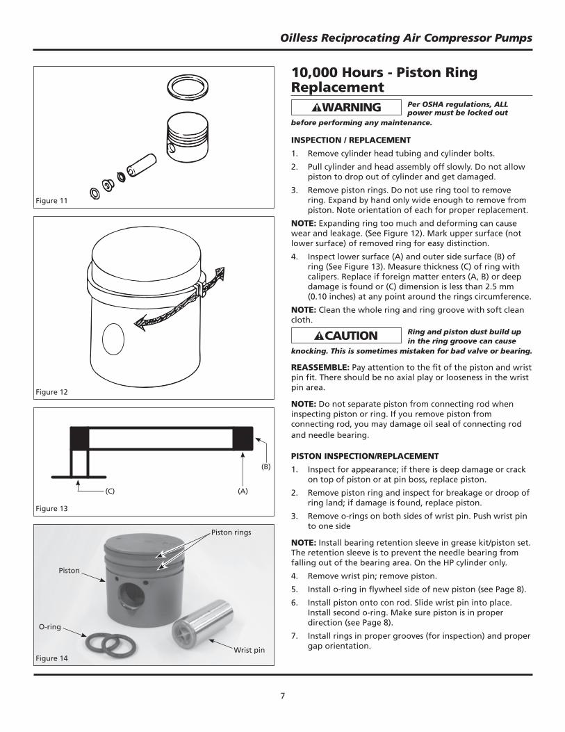
PISTON INSPECTION/REPLACEMENT
1. Inspect for appearance; if there is deep damage or crack on top of piston or at pin boss, replace piston.
2. Remove piston ring and inspect for breakage or droop of ring land; if damage is found, replace piston.
3. Remove o-rings on both sides of wrist pin. Push wrist pin to one side
NOTE: Install bearing retention sleeve in grease kit/piston set. The retention sleeve is to prevent the needle bearing from falling out of the bearing area. On the HP cylinder only.
4. Remove wrist pin; remove piston.
5. Install o-ring in fl ywheel side of new piston (see Page 8).
6. Install piston onto con rod. Slide wrist pin into place.Install second o-ring. Make sure piston is in proper direction (see Page 8).
7. Install rings in proper grooves (for inspection) and proper gap orientation.
Figure 11
Figure 12
Figure 13
(A)(C)
(B)
Figure 14
Piston rings
O-ring
Piston
Wrist pin

8
Oilless Reciprocating Air Compressor Pumps
10,000 Hours - Piston Ring Replacement (Continued) WRIST PIN BEARING REGREASE
1. Remove cylinder/head assembly and piston.
2. For low pressure wrist pin bearings, fi ll needle area with IP634500AJ Powerex approved grease.
Piston Orientation Chart for Oilless OPS / OPT Series
Pump Compressor Model Bore No. CylindersNo. of Piston Rings
per Piston Mark on Top of Piston
OPS010 65 mm 1 1Flywheel side
Fan Side
OPS030 65 mm 1 1Flywheel side
Fan Side
OPT050LP 105 mm 1 1 Flywheel side
Fan Side
HP 75 mm 1 2
OPT100LP 90 mm 2 1 Flywheel side
Fan Side
HP 75 mm 1 2
OPT150LP 105 mm 2 1 Flywheel side
Fan Side
HP 75 mm 1 2
3. For high pressure wrist pin bearings, replace wrist pin (#91924680). (OPT Pumps Only)
4. Replace cylinder/head assembly and piston as in procedures above.
5. Tighten all fi ttings and bolts to designated torques.
NOTE: When removing HP piston on two-stage pumps, remove piston and then insert retention sleeve having the same diameter of wrist pin or piston to small end of connecting rod. If not, you may drop or lose needles from the bearing, as HP needle bearing does not have support.
Fit piston by referring the ▲ marking on the top of the
piston surface and list on above chart.
NOTE: Gradually insert wrist pin while turning it. Inserting with force can damage oil seal of needle bearing.
* FOR LOW PRESSURE WRIST PIN BEARINGS ONLY
Figure 15
Small end of connecting rod
Small end of connecting rod
Wrist pin
NOTE: The orientation in which the pistons are reinstalled is very important. Improper placement will cause premature wear of the ring and piston.
Oilless ReciprocatingGrease6 Grams#IP634500AV
Powerex Oilless
Reciprocating Grease
6 Grams#IP634500AJ

9
Oilless Reciprocating Air Compressor Pumps
Figure 16
1. Insert the plastic retention sleeve which protects the needle bearing from dropping out.
Wrist Pin Bearing Seal Replacement (Replace Every 10,000 Hours) REPLACING OIL SEAL
Figure 17
2. Remove the two oil seals by using a screwdriver.
Figure 18
3. Clean both surfaces where oil seals are removed.
Figure 19
4. Push the oil seal into the small bearing end horizontally.
Figure 21
7. Apply a small volume of adhesive at several points.
Figure 22
8. Remove the retention sleeve inserted at the fi rst step.
NOTE: You may use a “C” clamp or two large washers and bolt with nut through the bearing. Then apply pressure to install the seals. This makes it easy to replace the seals without removing the crankshaft.
Figure 20
5. Press the oil seal with a C-clamp into the small bearing end.
6. Repeat on opposite side.
Pushing Board

10
Oilless Reciprocating Air Compressor Pumps
20,000 Hours - Connecting Rod, Wrist Pin and Crankshaft Per OSHA regulations, ALL
power must be locked out before performing any maintenance.
REPLACE CONNECTING ROD SET AND CRANKSHAFT AS A SET
Pressing bearing into connecting rod and connecting rod set into crankshaft requires special fi xtures. Without such fi xtures, the squareness and parallelism of each part will be affected.
REMOVE CYLINDER/HEAD ASSEMBLY AND PISTONS IN THIS ORDER
1. Bearing at large end of connecting rod: Replace if it does not move or feels stuck holding and moving small end of connecting rod.
2. Bearing of crankshaft: Replace if you feel some resistance when slowly turning shaft.
3. Bearing at wrist pin: Check for breakage of needle bearing and damage of cage.
DISASSEMBLING: CRANKSHAFT SET
1. Remove cylinder/head, assemblies and pistons.
2. Remove bolts from bearing cap and remove bearing cap.
3. Lightly tap shaft fan side with non-shock hammer (avoid metal hammer) and remove crankshaft. After bearing leaves the crankcase bore, pull connecting rod out as illustrated and remove it from crankcase (See Figure 23).
REASSEMBLY
1. Heat bearing housing of crankcase with industrial dryer or simple burner just the same as disassembling.
2. Insert crankshaft set into crankcase in reverse order of disassembling and insert bearing into housing.
3. Tap shaft from pulley side with non-shock hammer and insert it inwards.
4. Fit bearing case. Grease bearing housing of bearing case.
5. Replace pistons and cylinder/head assemblies per the inspection procedure listed previously.
Figure 23

11
Oilless Reciprocating Air Compressor Pumps
Maintenance Log
Date Maintenance Required Maintenance Performed

12
Maintenance Log
Date Maintenance Required Maintenance Performed
Oilless Reciprocating Air Compressor Pumps

13
Oilless Reciprocating Air Compressor Pumps
Notes

14
Oilless Reciprocating Air Compressor Pumps
Figure 24 - Replacement Parts Illustration for OPS010

15
Ref. Part Number for Model No. Description OPS010 Quantity
1 Cylinder 91000560 1
6 Cylinder head 91003630 1
16 Elbow (Unloader) 96800261 1
18 Unloader cap 91052041 1
27 Bolt (cylinder head) 96137835 4
33 Bolt (cylinder) 96137825 8
34 Bolt (bearing cap) 96137620 8
47 O-ring 91146550 1
51 Flywheel pulley 91201552 1
52 Parallel pin 91271550 1
62 Hex blot (fan, fl ywheel) 96992857 1
67 Piston set 91903640 1
67-1 Piston ring 91246640 1
72 Intake fi lter set 91906550 1
72-1 Intake fi lter ST073923AV 1
84 Screw (dust cover) 96131508 2
99 Seat (intake valve) 91301560 1
197 Lip seals wrist pin 97190162 2
200 Unloader set 91931561 1
500 Gasket set 91936640 1
600 Valve set with gasket 91933640 1
Oilless Reciprocating Air Compressor Pumps

16
Oilless Reciprocating Air Compressor Pumps
Figure 25 - Replacement Parts Illustration for OPS030

17
Oilless Reciprocating Air Compressor Pumps
Ref. Part Number for Model No. Description OPS030 Quantity
1 Cylinder 91000560 2
6 Cylinder head 91003640 2
16 Elbow (unloader) 96800261 1
17 Tee union assembly 96803261 1
20 Intake joint (1) 91345561 1
21 Intake joint (2) 91346571 1
24 Spring guide set 91932561 2
27 Bolt (cylinder head) 96137835 8
30 Flange (breather) 91176661 1
31 Bolt 96995831 20
33 Bolt (cylinder) 96137825 8
34 Bolt (bearing cap) 96137620 8
38 Filter (crank case) 91348690 1
47 O-ring 91146560 1
51 Flywheel pulley 91202560 1
52 Woodruff key 96600013 1
53 Hex nut 96994016 2
59 Fan 91220560 1
60 Cover (fan) 91134560 1
61 Hex bolt (fan, fl ywheel) 96992857 2
67 Piston set 91903640 2
67-1 Piston ring 91246640 2
72 Intake fi lter set 91907570 1
72-1 Intake fi lter ST073905AV 1
78 O-ring 96630032 2
79 Intake pipe 91407560 1
82 Screw (fi lter) 96131508 2
87 Tube 91909400 1
99 Seat (intake valve) 91301560 2
109 O-ring (intake joint) 96639906 2
193 Fan guard 91135560 2
195 Bolt (intake joint 1) 91095570 1
196 Bolt (intake joint 2) 91095560 1
197 Lip seals wrist pin 97190162 4
200 Unloader set 91931561 2
500 Gasket set 91936640 2
600 Valve set with gasket 91933640 2

18
Figure 26 - Replacement Parts Illustration for OPT050
Oilless Reciprocating Air Compressor Pumps

19
Ref. Part Number forNo. Description Model OPT050 Qty.
1 Cylinder (LP) 91000680 1
2 Cylinder (HP) 91947680 1
3 Liner 91177680 2
6 Cylinder Head (LP) 91004690 1
7 Cylinder Head (HP) 91014680 1
14 Elbow (Intercooler) 91415690 2
17 Tee Union Ass’y 96803261 2
18 Unloader Cap 91052451 2
20 Intake Joint 91345660 1
24 Spring Guide Set 91949694 2
27 Bolt (Cylinder Head) 96137850 10
30 Flange (Breather) 91176661 1
31 Bolt (Unloader Cap) 96995831 26
33 Bolt (Cylinder) 96137130 8
34 Bolt (Bearing Cap) 96137830 10
38 Filter (Crank Case) 91348690 1
47 O-ring 91146430 1
51 Flywheel Pulley 91201660 1
52 Woodruff Key 96600016 1
53 Hex Nut 96994016 4
54 Washer 96991512 1
59 Fan 91220690 1
60 Cover (Fan) 91134660 1
61 Hex Bolt (Fan, Flywheel) 96992817 2
67 Piston Set (LP) 91903680 1
67-1 Piston Ring (LP) 91236681 1
68 Piston Set (HP) 91910673 1
68-1 Piston Ring (HP) 91930680 1
68-2 Wrist Pin (Prepacked) 91924680 1
72 Intake Filter Set 91907660 1
72-1 Intake Filter ST073905AV 1
Ref. Part Number forNo. Description Model OPT050 Qty.
82 Screw (Filter) 96235304 2
87 Unloader Tube 91420661 1
99 Seat (Intake Valve) 91301691 2
108 Intercooler Flange 91403690 1
109 O-ring (Intake joint) 96639906 2
110 Connecting Pipe 91400660 1
120 Bolt (Intercooler) 91435692 2
143 O-Ring (Connecting Pipe) 96632825 1
145 O-Ring (Connecting Pipe) 96632835 1
157 Hex. Bolt (Intercooler) 96996460 6
165 Nut (Intercooler) 96994015 6
171 Connecting Pipe Set 91955721 1
173 Intercooler 91404680 1
174 Intercooler Flange (1) 91405690 1
175 Intercooler Flange (2) 91406690 1
176 Gasket (Intercooler) 91432690 2
193 Fan Guard 91144660 2
196 Bolt (Intake Joint) 91344690 2
197 Lip seals wrist pin 97191000 4
200 Unloader Set 91932682 2
500 Gasket Set (LP) 91936680 1
550 Gasket Set (HP) 91937681 1
600 Valve Set with Gasket (LP) 91933681 1
650 Valve Set with Gasket (HP) 91934683 1
Oilless Reciprocating Air Compressor Pumps

20
Oilless Reciprocating Air Compressor Pumps
Figure 27 - Replacement Parts Illustration for OPT100 and OPT150

21
Oilless Reciprocating Air Compressor Pumps
Ref. Part Number for Model No. Description OPT100 OPT150 Quantity
1 Cylinder (LP) 91000670 91000680 2 2 Cylinder (HP) 91947680 91947680 1 6 Cylinder head (LP) 91004670 91004690 2 7 Cylinder head (HP) 91014680 91014680 1 14 Elbow (Intercooler) 91415690 91415690 4 17 Tee union assembly 96803261 96803261 2 18 Unloader cap 91052451 91052451 3 20 Intake joint (1) 91345691 91345691 1 21 Intake joint (2) 91346690 91346690 1 24 Spring guide set 91949694 91949694 3 27 Bolt (Cylinder head) 96137850 96137850 16 31 Bolt (Unloader cap) 96995831 96995831 30 33 Bolt (Cylinder) 96137130 96137130 12 34 Bolt (Bearing cap) 96137830 96137830 10 38 Filter (Crank case) 91348690 91348690 1 47 O-ring (Bearing cap) 91146690 91146690 1 51 Flywheel pulley 91201590 91201690 1 52 Woodruff key 96600016 96600016 1 53 Hex nut 96994016 96994016 6 54 Washer (Intercooler) 96991512 96991512 1 59 Fan 91220690 91220690 1 60 Fan cover 91134690 91134690 1 61 Hexagon bolt (Fan) 96992817 96992817 1 62 Hexagon bolt (Flywheel) 96992833 96992833 1 63 Hexagon nut (Intake joint) 96382086 96382086 1 67 Piston set (LP) 91903670 91903680 2 67-1 Piston ring (LP) 91236671 91236681 2 68 Piston set (HP) 91910673 91910673 1 68-1 Piston rings (HP) 91930680 91930680 1 68-2 Wrist pin set (prepacked) 91924680 91924680 1 72 Intake fi lter set 91907590 91907690 1 72-1 Intake fi lter ST073907AV ST073907AV 1 78 O-ring (Intake pipe) 96630032 96630032 2 79 Inlet pipe 91407691 91407691 1 82 Bolt (Crankcase fi lter) 96131508 96131508 4 87 Unloader tube 91420690 91420690 1 96 Unloader tube 91419600 91419600 1 99 Wear pad, valve 91301691 91301691 3 108 Intercooler Joint 91403690 91403690 1 109 O-ring ( Intercooler Joint ) 96639906 96639906 3 110 Connecting Pipe 91402680 91402680 1 120 Bolt ( Intercooler) 91435692 91435692 4 131 Cover Bracket 91413690 91413690 2 143 O-ring ( Connecting Pipe ) 96632825 96632825 2 145 O-ring ( Connecting Pipe ) 96632835 96632835 1 157 Hex bolt ( Intercooler ) 96996460 96996460 6 165 Nut ( Intercooler ) 96994015 96994015 6 171 Connecting Pipe Set ( 1 ) 91955780 91955890 1 172 Connecting Pipe Set ( 2 ) 91955790 91955900 1 173 Intercooler 91404680 91404680 2 174 Intercooler Flange ( 1 ) 91405690 91405690 2 175 Intercooler Flange ( 2 ) 91406690 91406690 2 176 Gasket ( Intercooler ) 91432690 91432690 4 193 Fan Guard 91135690 91135690 2 195 Bolt ( Intake Joint 1 ) 91343690 91343690 1 196 Bolt ( Intake Joint 2 ) 91344690 91344690 2 197 Lip seals wrist pin 97191000 97191000 6 200 Unloader Set 91932682 91932682 3 500 Gasket Set ( LP ) 91936670 91936680 2 550 Gasket Set ( HP ) 91937681 91937681 1 600 Valve Set with Gasket ( LP ) 91934691 91933681 2 650 Valve Set with Gasket ( HP ) 91934683 91934683 1

22
Oilless Reciprocating Air Compressor Pumps
Notes

23
Oilless Reciprocating Air Compressor Pumps
Powerex Limited Warranty – Applicable to Non-OEM Customers in the U.S. & Canada Only
Warranty and Remedies.
(a) General. Powerex warrants each Compressor System, Vacuum System, Vacuum Pump, Compressor Air-End, or Powerex branded Accessory (collectively “Products”, individually each a “Product”) to be free from defects in material and workmanship (“Defects”) at the date of shipment. This warranty shall apply only to Products that are purchased and used in the United States of America and in Canada. EXCEPT AS SET FORTH BELOW, NO OTHER WARRANTY, WHETHER EXPRESS OR IMPLIED, INCLUDING ANYWARRANTY OF MERCHANTABILITY OR FITNESS FOR A PARTICULAR PURPOSE, SHALL EXIST IN CONNECTION WITH THE SALE OR USE OF SUCH PRODUCTS. TO THE EXTENT PERMITTED BY LAW, ANY AND ALL IMPLIED WARRANTIES ARE EXCLUDED. All warranty claims must be made in writing and delivered to Powerex in accordance with the procedures set forth on its website (www.powerexinc.com), or such claim shall be barred. Upon timely receipt of a warranty claim, Powerex shall inspect the Product claimed to have a Defect, and Powerex shall repair, or, at its option, replace, free of charge, any Product which it determines to have had a Defect; provided, however, that if circumstances are such as to preclude the remedying of Defect by repair or replacement, Powerex shall, upon return of the Product, refund to buyer any part of the purchase price of such Products paid to Powerex. Freight for returning Products to Powerex for inspection shall be paid by buyer. The warranties and remedies herein are the sole and exclusive remedy for any breach of warranty or for any other claim based on any Defect, or non-performance of the Products, whether based upon contract, warranty or negligence.(b) (i) Standard Period of Warranty – Parts and Labor - The purchase of any system includes our standard warranty. Powerex warrants and represents all Products shall be free from Defects for the fi rst eighteen (18) months from the date of shipment by Powerex, or twelve (12) months from the documented date of startup, or fi ve thousand (5,000) hours of use, whichever occurs fi rst. During such warranty period, Powerex shall be fully liable for all Defects in the Products (the “Product Defects”), i.e., all costs of repair or replacement, which may include “in and out” charges, so long as the Products are located in the United States or Canada, and the Products are reasonably located and accessible by service personnel for removal. “In and out” charges include the costs of removing a Product from buyer’s equipment for repair or replacement. (ii) Premium Period of Warranty – Parts and Labor - In order to be eligible for premium warranty coverage, a premium warranty for each system must be purchased when order is placed. Powerex warrants and represents all Products shall be free from Defects for the fi rst thirty (30) months from the date of shipment by Powerex, or twenty-four (24) months from the documented date of startup, or seven thousand fi ve hundred (7,500) hours of use, whichever occurs fi rst. During such warranty period, Powerex shall be fully liable for all Defects in the Products (the “Product Defects”), i.e., all costs of repair or replacement, which may include “in and out” charges, so long as the Products are located in the United States or Canada, and the Products are reasonably located and accessible by service personnel for removal. “In and out” charges include the costs of removing a Product from buyer’s equipment for repair or replacement.(c) Additional Period of Warranty – Parts Only (No Labor). In addition to the above, Powerex warrants each Powerex branded Compressor Air- End and Vacuum Pump shall be free of Defects for a period of forty-two (42) months from the date of shipment by Powerex, or thirty-six (36) months from the documented date of startup, or ten thousand (10,000) hours of use, whichever occurs fi rst. Supplier’s repair or replacement of any Product shall not extend the period of any warranty of any Product. This warranty applies to the exchange of part(s) found to be defective by an Authorized Powerex Service Representative only.(d) Replacement Pumps – Parts Only (No Labor). For any replacement Air-End or Vacuum Pumps installed on a Powerex manufactured system or unit after any initial warranty period has expired or where another warranty does not apply for any reason, Powerex warrants that the Air-End or Vacuum Pumps shall be free of Defects for a period of thirty-six (36) months from the date of shipment by Powerex or ten thousand (10,000)hours of use, whichever comes fi rst. For any replacement Air-End or Vacuum Pumps installed on a system that was not manufactured by Powerex after any initial warranty period has expired or where another warranty does not apply for any reason, Powerex warrants that the Air-End or Vacuum Pumps shall be free of Defects for the fi rst twelve (12) months from the date of shipment by Powerex. Supplier’s repair or replacement of any Product shall not extend the period of any warranty of any Product. This warranty applies to the exchange of part(s) found to be defective by an Authorized Powerex Service Representative only.(e) Replacement Motors – Parts Only (No Labor). For any replacement motor installed on a Powerex manufactured system or unit after any initial warranty period has expired or where another warranty does not apply for any reason, Powerex warrants that the replacement motor shall be free of Defects for the fi rst twelve (12) months from the date of shipment by Powerex. For any replacement motor installed on a system or unit that was not manufactured by Powerex after any initial warranty period has expired or where another warranty does not apply for any reason, Powerex warrants that the replacement motor shall be free of Defects for the fi rst ninety (90) days from the date of shipment by Powerex. Supplier’s repair or replacement of any Product shall not extend the period of any warranty of any Product. This warranty applies to the exchange of part(s) found to be defective by an Authorized Powerex Service Representative only.(f) Replacement Parts – Parts Only (No Labor). For other replacement parts besides motors, Air-End or Vacuum Pumps installed on a Powerex manufactured system or unit after any initial warranty period has expired or where another warranty does not apply for any reason, Powerex warrants that such replacement parts will be free from Defects for the fi rst twelve (12) months from the date of shipment by Powerex. For other replacement parts besides motors, Air-End or Vacuum Pumps installed on a system or unit that was not manufactured by Powerex after any initial warranty period has expired or where another warranty does not apply for any reason, Powerex makes no warranties. Supplier’s repair or replacement of any Product shall not extend the period of any warranty of any Product. This warranty applies to the exchange of part(s) found to be defective by an Authorized Powerex Service Representative only.(g) Coverage. The warranty provided herein applies to Powerex manufactured units or systems only.(h) Exceptions. Notwithstanding anything to the contrary herein, Powerex shall have no warranty obligations with respect to Products:
(i) that have not been installed in accordance with Powerex’s written specifi cations and instructions;(ii) that have not been maintained in accordance with Powerex’s written instructions;(iii) that have been materially modifi ed without the prior written approval of Powerex; or(iv) that experience failures resulting from operation, either intentional or otherwise, in excess of rated capacities or in an otherwise
improper manner.

Powerex • 150 Production Drive • Harrison, OH 45030 • USA1-888-769-7979 • www.powerexinc.com 24
Oilless Reciprocating Air Compressor Pumps
(i) The warranty provided herein shall not apply to:(i) any defects arising from corrosion, abrasion, use of insoluble lubricants, or negligent attendance to or faulty operation of the
Products;(ii) ordinary wear and tear of the Products; (iii) defects arising from abnormal conditions of temperature, dirt or corrosive matter; or (iv) any OEM component which is shipped by Powerex with the original manufacturer’s warranty, which shall be the sole applicable
warranty for such component.Limitation of Liability. NOTWITHSTANDING ANYTHING TO THE CONTRARY HEREIN, TO THE EXTENT ALLOWABLE UNDER APPLICABLE LAW, UNDER NO CIRCUMSTANCES SHALL POWEREX BE LIABLE FOR ANY INCIDENTAL, CONSEQUENTAL, PUNITIVE, SPECULATIVE OR INDIRECT LOSSES OR DAMAGES WHATSOEVER ARISING OUT OF OR IN ANY WAY RELATED TO ANY OF THE PRODUCTS OR GOODS SOLD OR AGREED TO BE SOLD BY POWEREX TO BUYER. TO THE EXTENT ALLOWABLE UNDER APPLICABLE LAW, POWEREX’S LIABILITY IN ALL EVENTS IS LIMITED TO, AND SHALL NOT EXCEED, THE PURCHASE PRICE PAID.Warranty Disclaimer. Powerex has made a diligent effort to illustrate and describe the Products in its literature, including its Price Book,accurately; however, such illustrations and descriptions are for the sole purpose of identifi cation, and do not express or imply a warranty that the Products are merchantable, or fi t for a particular purpose, or that the Products will necessarily conform to the illustrations or descriptions.Product Suitability. Many jurisdictions have codes and regulations governing sales, construction, installation, and/or use of Products for certain purposes, which may vary from those in neighboring areas. While Powerex attempts to assure that its Products comply with such codes, it cannot guarantee compliance, and cannot be responsible for how the product is installed or used. Before purchase and use of a Product, please review the Product applications, and national and local codes and regulations, and be sure that the Product, installation, and use will comply with them.Claims. Any non-warranty claims pertaining to the Products must be fi led with Powerex within 6 months of the invoice date, or they will not be honored. Prices, discounts, and terms are subject to change without notice or as stipulated in specifi c Product quotations. Powerex shall not be liable for any delay or failure arising out of acts of the public enemy, fi re, fl ood, or any disaster, labor trouble, riot or disorder, delay in the supply of materials or any other cause, whether similar or dissimilar, beyond the control of Company. All shipments are carefully inspected and counted before leaving the factory. Please inspect carefully any receipt of Products noting any discrepancy or damage on the carrier’s freight bill at the time of delivery. Discrepancies or damage which obviously occurred in transit are the carrier’s responsibility and related claims should be made promptly directly to the carrier. Returned Products will not be accepted without prior written authorization by Powerex and deductions from invoices for shortage or damage claims will not be allowed. UNLESS OTHERWISE AGREED TO IN WRITING, THE TERMS AND CONDITIONS CONTAINED IN THIS LIMITED WARRANTY WILL CONTROL IN ANY TRANSACTION WITH POWEREX. Any different or confl icting terms as may appear on any order form now or later submitted by the buyer will not control. All orders are subject to acceptance by Powerex.