DEPLOYING WIRELESS BROADBAND IN TVWS FREQUENCIES TO … · WHITE PAPER | Deploying Wireless...
16
DEPLOYING WIRELESS BROADBAND IN TVWS FREQUENCIES TO BRIDGE THE DIGITAL DIVIDE WHITE PAPER POWERFUL. VERSATILE. RELIABLE.
Transcript of DEPLOYING WIRELESS BROADBAND IN TVWS FREQUENCIES TO … · WHITE PAPER | Deploying Wireless...
DEPLOYING WIRELESS BROADBAND IN TVWS FREQUENCIES TO BRIDGE THE DIGITAL DIVIDE
WHITE PAPER
POWERFUL. VERSATILE. RELIABLE.

WHITE PAPER | Deploying Wireless Broadband in TVWS Frequencies to Bridge the Digital Divide
TABLE OF CONTENTS
Introduction 3
Identifying the Need 3
Planning the Solution 4
Obtaining TVWS Spectrum 7
Designing the Network 9
Deploying the Network 10
Realizing a Successful Outcome 11
Conclusion 12
Appendix 13

Page 3 of 16WHITE PAPER | Deploying Wireless Broadband in TVWS Frequencies to Bridge the Digital Divide
INTRODUCTION
Delivering Internet access to rural customers is no easy task.
Many residences and businesses in small towns and rural areas all over the world lack the type of ready access to the Internet heavily-populated areas enjoy, often with more than one Internet service provider (ISP) from which to choose.
This has been termed the Digital Divide.
Rural customers often live some distance from the nearest community. Wireline service providers that serve such areas generally favor a fiber optic cable network. Certainly, fiber can deliver high-speed Internet connections but at a price. The cost to connect relatively few rural customers over a wide area with a high-capacity fiber optic system can run thousands of dollars per connection.
By contrast, wireless broadband systems offer a better alternative for these applications and in many cases, can be deployed efficiently and at lower capital cost per customer compared to fiber. These wireless systems typically utilize unlicensed frequencies such as 900 MHz or 5 GHz. Connections between a base station and a remote terminal at the customer premise are often achieved through line-of-sight (LOS) transmission.
There are instances, however, where LOS transmission is not possible because of hilly or mountainous terrain and dense foliage coverage. In such circumstances, a wireless broadband system operating in television white space (TVWS) frequencies in the UHF (470-698 MHz) band can facilitate non-line-of-sight (NLOS) transmission to connect those few, hard-to-reach customers. Note that the 900 MHz spectrum traditionally has performed well for NLOS applications; however, 900 MHz is overused, and the resultant radio frequency (RF) noise limits the range and capacity of systems operating in this band.
This white paper describes the actual TVWS deployment using Redline’s RDL-3000 XP Virtual Fiber™ wireless broadband system by ABC Communications (ABC), an Internet service provider (ISP) based in the Province of British Columbia (BC) in Western Canada. ABC’s headquarters are in Quensel, BC.
This paper discusses all aspects of the project from network planning to service commissioning, and addresses the key issues involved with using TVWS frequencies for bridging the Digital Divide.
IDENTIFYING THE NEED
ABC is a leading ISP to residences and businesses in over 100 communities in central BC. From its headquarters in Quensel, ABC provides services in Burns Lake, Vanderhoof, 100 Mile House, Kelowna, Penticton, Prince George and Vancouver. The company is a trusted supplier to the BC government connecting ministry offices and schools throughout the province, helping bridge the Digital Divide.
Initially with dial-up lines, ABC now provides Internet access via its extensive wireless broadband network. ABC holds 3.5 GHz licensed spectrum throughout much of the BC interior and has extensive WiMAX and LTE experience. Their private wireless network includes 180 towers across the province, from the US border through to Northern BC. Furthermore, ABC operates a fiber optic backbone network that links over 30 cities to network centers in Vancouver and Prince George, a city of about 75,000 people in east-central BC, roughly 500 miles north of Vancouver.

Page 4 of 16WHITE PAPER | Deploying Wireless Broadband in TVWS Frequencies to Bridge the Digital Divide
ABC is addressing a big need for reliable Internet service throughout central BC.
Consider this. Sixty percent of BC’s 4.8 million population lives in the two largest metro areas –Vancouver and Victoria, the province’s capital – concentrated in BC’s lower southwest on the Pacific coast. The remaining 40 percent, more than 1.8 million people, reside in a vast land area covering nearly 360,000 square miles. There are dozens of small towns and communities throughout BC in rural, open spaces.
The challenge for ISPs like ABC is how to deliver high-speed Internet access to residents and business in these small, dispersed rural communities efficiently and cost-effectively.
PLANNING THE SOLUTION
In early 2017, ABC began investigating several wireless alternatives for extending Internet access into these small, rural communities. Among the alternatives, the company considered TVWS seeing it used with some success in other countries.
TVWS in low-band UHF frequencies exhibits propagation characteristics of long range and the ability to penetrate obstacles such as heavy tree foliage and sometimes, even buildings.
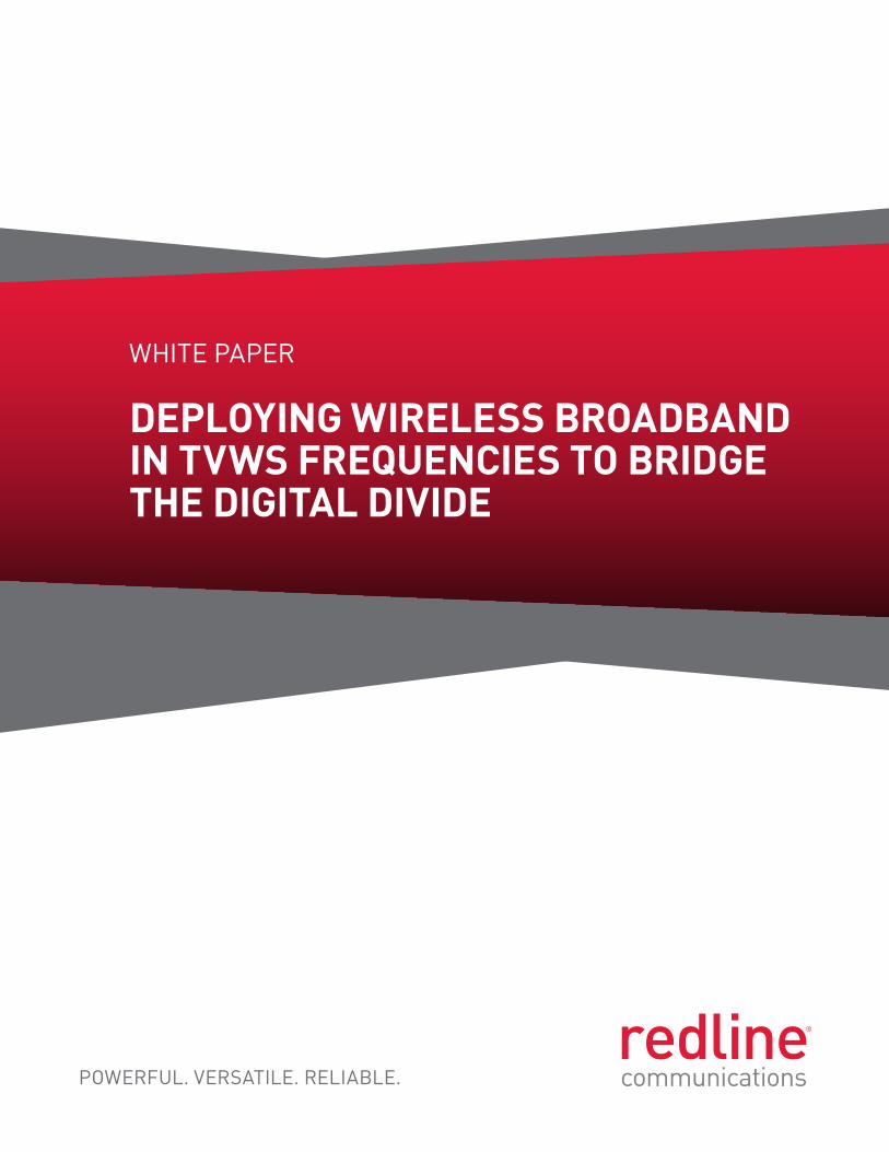
ABC picked several locations in its territory and tested the viability of TVWS by conducting spectrum analyses. The test results are summarized in Exhibit 1.
VancouverPenticton
Kelowna
Vanderhoof
Burns LakePrince George
Quesnel
100 Mile House
BRITISH COLUMBIA
Page 5 of 16WHITE PAPER | Deploying Wireless Broadband in TVWS Frequencies to Bridge the Digital Divide
AREA/SITE NAMETEST LOCATION
(LAT/LONG)TOWER HEIGHT
LINE OF SIGHT (LOS)?TEST
HEIGHTOVERALL
ASSESSMENT
BURNS LAKE53.871277/ -126.012043
30 m Above tree line 3 mLow noise floor, spurious spikes as high as -78 dBm
QUESNEL
Milburn Mtn53.028142/ -122.747682
20 m
Nothing within 15m, mountain top with clear view to surrounding tower sites
3 mA couple of channels clearly in use
Nazko School52.929788/ -123.563033
N/A
Nothing within 15m, open parking lot. Location at bottom of valley
3 m Clean spectrum
Nazko Reserve52.943979/ -123.583829
N/A
Nothing within 15m, open parking lot. Location at bottom of valley
3 m Clean spectrum
FAULDER
Faulder South49.613167/ -119.785417
20 mRelatively clear view of surrounding valley
3 mA couple of channels clearly in use
Faulder North49.622861/ -119.781944
20 mRelatively clear view of surrounding valley
3 mA couple of channels clearly in use
Fishmeadow49.665624/ -119.797691
N/ARelatively clear view of surrounding valley
3 mA couple of channels clearly in use
BEAVERDELL
Carmi Tower49.493269/ -119.124303
6 mMinimal obstruction, hill top looking down on valley
3 m Clean spectrum
Exhibit 1 TVWS Spectrum Analysis, Various Prospective Sites, -80 dBm Noise Floor Objective
Source: ABC Communications, tests conducted May 31-June 14, 2017

Page 6 of 16WHITE PAPER | Deploying Wireless Broadband in TVWS Frequencies to Bridge the Digital Divide
Preliminary tests showed that some sites were more attractive than others, mainly due to the absence of interfering signal sources in the area.
Burns Lake turned out to be an attractive location for TVWS deployment for several reasons. ABC already provides wired and wireless Internet access in Burns Lake, a rural
community of 2,400 people located in BC’s Lake District, about 140 miles west of Prince George.
Roughly 20 miles to the southwest of Burns Lake, though, is residential and recreational area with several hundred homes along Francois Lake and the Nechako Reservoir. Homes in this area are occupied both year-round and on a seasonal basis.
This area is lacking Internet access simply because these homes are difficult to reach. The terrain consists of rolling hills with many small valleys and drainages with extensive deciduous tree cover.
In the middle of the target area is Verdun Mountain, the high point of land at a 3,700 foot elevation, and about 1,000 feet above the surrounding area in all directions. Verdun Mtn. makes a natural place to locate a base station for transmitting high-speed signals to subscriber units at the lower elevations.
Francois Lake
EXHIBIT 2 BURNS LAKE: TVWS TARGET COVERAGE AREA
Source: Redline Communications, ABC Communications

Page 7 of 16WHITE PAPER | Deploying Wireless Broadband in TVWS Frequencies to Bridge the Digital Divide
The other key factor here is that ABC already operates a 900 MHz system transmitting from an existing tower on Verdun Mtn. to serve 10 subscribers in the immediate area. Burns Lake area was selected as the first TVWS deployment site given the 120 homes to be served and the availability of tower space on Verdun Mtn.
Yet the Verdun Mtn. site poses challenges. Despite the tower location being above most of the surrounding terrain, it is still not high enough to provide a steep penetration angle. Wireless signals must be transmitted through several layers of trees and in some cases over rolling hills.
After discussions with Redline’s system engineers, ABC determined that deploying Redline’s TVWS radio solution would provide the required data throughput performance while operating in NLOS or near-line-of-sight (nLOS) transmission modes to overcome obstacles the terrain posed.
OBTAINING TVWS SPECTRUM
Wireless ISPs (WISPs) like ABC must take several key steps to design a high-performance TVWS system.The first and foremost is to gain access to TVWS spectrum.
In many countries around the world, WISPs can query a national database maintained by a spectrum administrator designated by the country’s telecommunications regulator. The database typically shows the full range of available TVWS channels in the planned deployment area, along with those channels that are already occupied. A WISP can apply to use any of those available channels on an exclusive basis.In Canada, there is no designated database administrator nor has the Federal government established formal rules for use of TVWS spectrum. Nonetheless, WISPs interested in TVWS can apply for a ‘developmental’ license to use several assigned channels, ostensibly for testing purposes.
In this case, ABC obtained a license from Innovation, Science and Economic Development Canada (ISED), a branch of the
Canadian government that helps companies bring innovative technology products and services to market.
ISED awarded ABC a developmental license that allows them to deploy TVWS services using three 6 MHz channels, specifically, Channel 25 (536-542 MHz), Channel 26 (542-548 MHz) and Channel 27 (548-554 MHz). The license specified that the maximum radio transmitter eradiated power(ERP) be limited to 2.161 watts (W) or +33 dBm.
TESTING THE SPECTRUM
The second step is to verify that the assigned channels can operate free of radio frequency (RF) noise and interference.
With no spectrum database available to determine channel assignments in adjacent bands, ABC conducted its own RF sweep tests. These tests involve scanning or ‘sweeping’ specific RF frequencies in a band to detect signals being received in that band from distant transmitters. As the frequency of the receiver is adjusted with each sweep, a display indicates the power of the signals received at each frequency and if the received signal level is below the specified noise floor, or not.
RF sweep tests normally are conducted using spectrum analyzers. In this instance, Redline supplied ABC with a RDL-3000 XP Ellipse base station to conduct the tests.
BEST PRACTICES TIP:
Even if a TVWS database is available, Redline recommends as a ‘best practice’ to conduct RF sweep tests to verify the quality of the assigned channels in the planned operating areas. Our field experience has shown in some instances assigned TV channels which were supposed to be vacant were active.

Page 8 of 16WHITE PAPER | Deploying Wireless Broadband in TVWS Frequencies to Bridge the Digital Divide
Verdun Mountain Sites
Source: ABC Communications
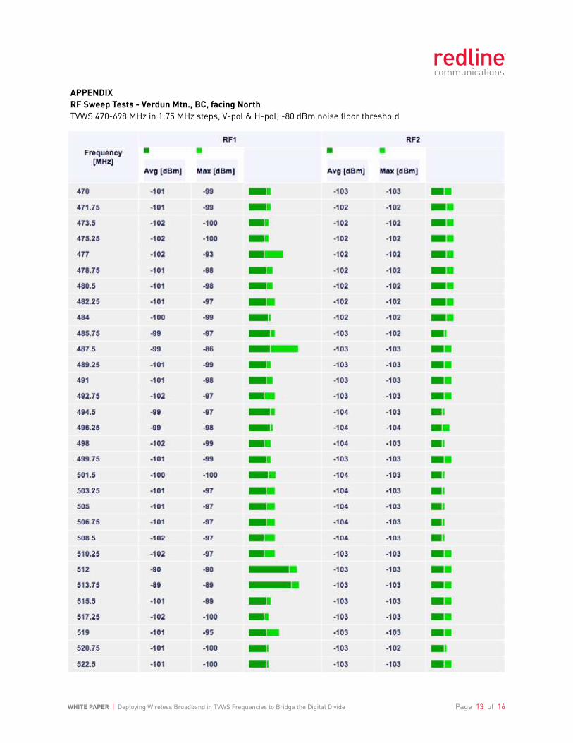
This directional testing covered the areas where customers are located with respect to the base station. Even though ABC would be operating in just three channels in the 536-554 MHz range, each directional RF sweep covered the full UHF frequency band from 470 to 698 MHz in steps of 1.75 MHz. This means that each directional test yielded a total of 130 entries. Furthermore, a built-in feature of the Ellipse radio is that because it operates in a 2x2 multiple in-multiple out (MIMO) antenna arrangement, the radio has separate ports – RF1 and RF2 – that allow for simultaneous measuring of receive signals on both the vertical polarization (V-pol) and horizontal polarization (H-pol).
ABC conducted RF sweep test results using Ellipse radio across the full UHF band from 470 MHz to 698 MHz, even though WISPs in Canada are limited to a range of 512 MHz to 698 MHz.
ABC wanted to ‘see’ everything around it from the Verdun Mtn. site. Exhibit 3 is an excerpt of the full RF sweep test showing results in ABC’s assigned 536-554 MHz frequency band for the North direction from Verdun Mtn. for both V-pol and H-pol.
Full test results across all frequencies in the North direction are shown in the Appendix.
Even though the Ellipse is a radio transmitter and receiver, the transmitter portion is turned off during the test. The Ellipse’s tunable radio receiver in ‘listen-only mode’ can detect and measure the levels of RF signals already present in the area. Such analyses were intended to assure ABC’s network planners that operation in their assigned TVWS
channels would be sufficiently immune from interference.
ABC’s RF sweep tests were extensive. From the Verdun Mtn. site, ABC systems engineers conducted RF sweeps in six different directions: East, North, Northeast, Northwest, Southeast and South.

Page 9 of 16WHITE PAPER | Deploying Wireless Broadband in TVWS Frequencies to Bridge the Digital Divide
EXHIBIT 3 TVWS SPECTRUM ANALYSIS: 536-554 MHZ, VERDUN MTN., NORTH-FACING SECTOR
Source: Redline Communications
RF1 RF2
Avg [dBm] Max [dBm] Avg [dBm] Max [dBm]
534.75 -100 -98 -100 -99
536.5 -103 -102 -103 -103
538.25 -102 -102 -103 -103
540 -102 -101 -103 -102
541.75 -102 -98 -103 -103
543.5 -102 -100 -103 -103
545.25 -102 -100 -103 -103
547 -102 -100 -103 -103
548.75 -101 -100 -102 -102
550.5 -102 -101 -103 -103
552.25 -103 -101 -104 -103
554 -103 -102 -104 -104
555.75 -103 -101 -104 -103
Frequency [MHz]
The data confirmed that ABC’s assigned TVWS channels in the North sector, received levels averaging -102 to -103 dBm, well below the -80 dBm noise floor objective.
DESIGNING THE NETWORK
Once the coverage area spectrum analysis proved that ABC could operate TVWS assigned channels without interference, the third step is to model the transmission pattern and signal strength that could be achieved from the Ellipse base station on Verdun Mtn. into the surrounding area.
Redline conducted computer-based RF simulations using an off-the-shelf RF modeling program with numerous
inputs including base station location, geographic information, operating frequencies, antenna type and gain, height above ground level (AGL), and ERP.
Exhibit 4 shows the resulting RF pattern for download data throughput speeds that ABC can expect in the target area given the terrain and distances with the specified transmission parameters.

Page 10 of 16WHITE PAPER | Deploying Wireless Broadband in TVWS Frequencies to Bridge the Digital Divide
EXHIBIT 4: TVWS COVERAGE AREA ANALYSIS FROM VERDUN MTN.
Source: Redline Communications; Red areas=25 Mb/s, Yellow areas=15 Mb/s
This type of analysis is very important because it provided ABC with the planning data it needed to identify the type of service it could offer different customers located throughout the coverage area. More important, it established that Verdun Mtn. was a very suitable location from which to deliver these services to prospective customers using TVWS frequencies.
DEPLOYING THE NETWORK
With Redline’s guidance, ABC deployed a TVWS solution in a point-to-multipoint (PMP) configuration using Redline’s RDL-3000 XP Virtual Fiber™ system for those NLOS connections.
The RDL-3000 system is comprised of the Ellipse base station and multiple Enterprise remote terminals, one at each customer location.The RDL-3000 XP is a highly-versatile wireless broadband system that can be software-programmed to operate in various sub-6 GHz frequency bands including UHF (470-698 MHz), 2, 3 and 5 GHz unlicensed or lightly-licensed spectrum¹.
RDL-3000 XP has a software-adjustable channel size of up to 20 MHz and can deliver high data throughput capacity of up to 186.6 Mb/s per sector, in a 90-degree sector that Redline recommends. More importantly, the system is very reliable, designed for rugged, remote environments with a mean time between failure (MTBF) of more than 20 years.

Page 11 of 16WHITE PAPER | Deploying Wireless Broadband in TVWS Frequencies to Bridge the Digital Divide
For this application, ABC initially planned to serve 20-30 subscribers per sector. To achieve high-speed connections, ABC was allowed by ISED to combine two adjacent 6 MHz TVWS channels for transmission over a 12 MHz channel that the Ellipse base station can accommodate. ABC technicians installed the Ellipse programmed for this 12 MHz channel on the existing 110 foot tower on the top of Verdun Mtn. With a 12 dBi, 90-degree panel sector antenna attached, the Ellipse is mounted close to the 100 foot level and is pointing toward the North sector. The ERP level on the Ellipse transmitter is set at +22 dBm to reach multiple subscribers; that ERP is well within the ISED license specification of +33 dBm. Note that the Ellipse has a maximum ERP of +31 dBm combined transmit power, in MIMO mode and frequency-band specific. This feature provides ABC with capacity to increase power levels if needed to expand coverage.
Download the Ellipse datasheet: http://rdlcom.com/resources/download?file=62
The coverage area has a 20-30 Km radius although ABC strives to keep distances to subscribers within a 15-20 Km radius. For the most part, transmission paths are LOS but the TVWS application is well-suited for both near LOS (nLOS) and NLOS connections that ABC needed to reach hard-to-reach customers.
At each subscriber location, ABC installed an Enterprise remote terminal connected to a dual polarity 2 ft., 11 dBi gain antenna. The antenna is mounted 6 feet or more above each building’s roof line and is pointing towards the Ellipse base station on Verdun Mtn. The Enterprise is an outdoor unit that ABC installed on the side of the building witth a short coaxial cable connection to the antenna.
Download the Enterprise datasheet: http://rdlcom.com/resources/download?file=66
The field installation activity was handled by experienced ABC field technicians who worked closely with Redline systems engineers to make all required adjustments
REALIZING A SUCCESSFUL OUTCOME
ABC successfully deployed TVWS in the Burns Lake area from Verdun Mtn. to customers who now are enjoying high-speed wireless Internet connections where none existed before. Customer feedback has been very positive.
ABC offers a menu of service packages to meet a variety of customer needs. Residential service packages range from ‘Residential Basic’ with download speed of 1.5 Mbps and up to 25 Gb monthly data usage capacity to the high-end ‘Residential Mega’, available in select areas, with a download speed of 15 Mbps and 250 Gb monthly usage. Intermediate speed and data capacity packages are available. ABC offers a similar suite of services for businesses.

Page 12 of 16WHITE PAPER | Deploying Wireless Broadband in TVWS Frequencies to Bridge the Digital Divide
“Redline has been very helpful in making
this product perform well for our
application and has provided us with a
great experience. We anticipate growing
our deployment of the TVWS product in
the future as we are able to gain access to
more spectrum licenses in BC.”
-Falko Kadenbach, ABC VP
CONCLUSION
Deploying wireless broadband services in TVWS frequencies solves Internet access connection problems for homes and businesses in NLOS applications where no other solution exists.Here are the key takeaways:
1. Develop detailed network plan. We cannot overstate this criterion. At the outset, identify your target customer locations, the topography of the area and the services to be delivered. Custom RF modeling assistance is available from Redline to help you determine the optimal location
of the base stations and to predict the data throughput performance required to connect each customer. A sound network plan will assure service reliability and can save on equipment investment in the long run.
2. Obtain TVWS spectrum. Apply to the designated database administrator to obtain TVWS channel assignments for your company. Usually this can be accomplished on-line if a TVWS database is established, or directly through the national telecommunications regulator.
3. Test, Test, Test. Confirm that your assigned TVWS channels will operate free of RF interference and noise using generally-accepted spectrum analyses techniques. Testing over a wide spectrum range beyond the assigned channels can be done at incremental time and cost but will give you a very good assessment of the RF environment in which you will operate.
4. Use Proven TVWS Radio Equipment. Select a radio system that is powerful, versatile and reliable. You want a system that it is field-proven and delivers the data speeds that your customers demand yet is easy to install and requires no maintenance. Redline’s RDL-3000 XP Virtual Fiber™ system operating in the UHF band is a leading TVWS radio that meets these parameters.
5. Rely on RF Expertise. Every situation is different and even the best RF engineers can take advantage of the knowledge, experience and expertise of Redline’s technical support teams. Redline RF design and system engineers have extensive experience in the complete cycle of TVWS network design, field testing and system deployment.
Understand that TVWS is a solution best-suited to those exceptional situations where NLOS transmission is the only alternative. In rare instances, TVWS may be the only solution. More often than not, TVWS will complement a wireless broadband system that serves customers using LOS transmission in other unlicensed sub-6 GHz bands.
In the end, Redline’s TVWS is a viable wireless solution to bridging the Digital Divide where no other technical or economic option exists.
ABC’s initial deployment connected 20 homes in the Fall of 2017. The company plans to add 100 homes in 2018. Furthermore, by March 2018, ABC plans to migrate 10 customers to TVWS from an existing 900 MHz service that is very susceptible to RF interference and NLOS impediments.
ABC confirms that Redline is one of a small group of manufacturers of TVWS products, and a good fit for its application. The company adds that Redline was very helpful in working with its technical team and assisting in RF sweep testing prior to procurement.
ABC expressed its appreciation to Redline and its distributor Partner, Alliance Corporation for their support and responsiveness throughout the network planning, equipment procurement and delivery process.
Page 13 of 16WHITE PAPER | Deploying Wireless Broadband in TVWS Frequencies to Bridge the Digital Divide
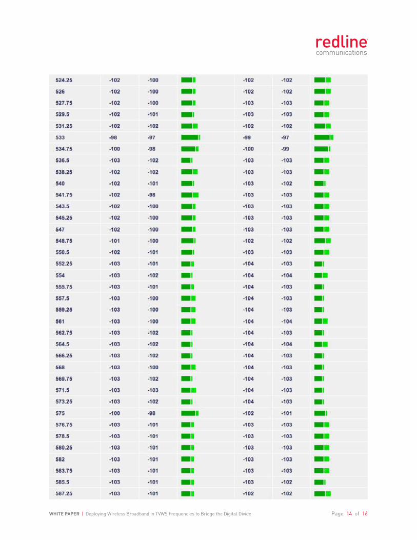
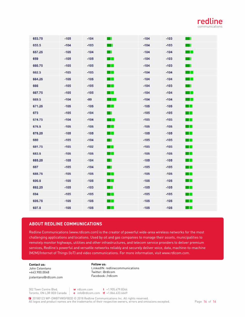
APPENDIXRF Sweep Tests - Verdun Mtn., BC, facing North TVWS 470-698 MHz in 1.75 MHz steps, V-pol & H-pol; -80 dBm noise floor threshold
Page 14 of 16WHITE PAPER | Deploying Wireless Broadband in TVWS Frequencies to Bridge the Digital Divide

Page 15 of 16WHITE PAPER | Deploying Wireless Broadband in TVWS Frequencies to Bridge the Digital Divide
20180123 WP-DWBTVWSFBDD © 2018 Redline Communications Inc. All rights reserved.All logos and product names are the trademarks of their respective owners, errors and omissions excepted.
302 Town Centre Blvd. Toronto, ON L3R 0E8 Canada
w rdlcom.com t +1.905.479.8344 e [email protected] tf +1.866.633.6669
Page 16 of 16
ABOUT REDLINE COMMUNICATIONS
Redline Communications (www.rdlcom.com) is the creator of powerful wide-area wireless networks for the most challenging applications and locations. Used by oil and gas companies to manage their assets, municipalities to remotely monitor highways, utilities and other infrastructures, and telecom service providers to deliver premium services, Redline’s powerful and versatile networks reliably and securely deliver voice, data, machine-to-machine (M2M)/Internet of Things (IoT) and video communications. For more information, visit www.rdlcom.com.
Contact us:John Celentano+443.900.0048
Follow us:LinkedIN: redlinecommunicationsTwitter: @rdlcomFacebook: /rdlcom


![PAPER Measurement-Based Spectrum Database for ......(Ofcom) in the UK started a TVWS pilot program for database-aided TVWS utilization in July, 2014 [10], [14]. For the TVWS pilot,](https://static.fdocuments.net/doc/165x107/5fcf0d759f274140c51ed668/paper-measurement-based-spectrum-database-for-ofcom-in-the-uk-started.jpg)