Depleted Uranium as Aggregate in Concrete Shielding Material
28
Depleted Uranium as Aggregate in Concrete Shielding Material Les Dole Catherine Mattus Juan Ferrada Oak Ridge National Laboratory, P.O. Box 2008: Oak Ridge, TN 37831-6273 Phone: (865) 576-4319; E-mail: [email protected] *Managed by UT-Battelle, LLC, for the U.S. Department of Energy under contract DE-AC05-00OR22725. The submitted manuscript has been authored by a contractor of the U.S. Government under contract DE-AC05-00OR22725. Accordingly, the U.S. Government retains a nonexclusive, royalty-free license to publish or reproduce the published form of this contribution, or allow others to do so, for U.S. Government purposes.
Transcript of Depleted Uranium as Aggregate in Concrete Shielding Material

Depleted Uranium as Aggregate in Concrete Shielding Material
Les DoleCatherine Mattus
Juan FerradaOak Ridge National Laboratory,
P.O. Box 2008: Oak Ridge, TN 37831-6273Phone: (865) 576-4319; E-mail: [email protected]
*Managed by UT-Battelle, LLC, for the U.S. Department of Energy under contract DE-AC05-00OR22725. The submitted manuscript has been authored by a contractor of the U.S. Government under contract DE-AC05-00OR22725. Accordingly, the U.S. Government retains a nonexclusive, royalty-free license to publish or reproduce the published form of this contribution, or allow others to do so, for U.S. Government purposes.

2
Conclusions• Combinations of gamma-absorbing depleted
uranium (DU) and neutron-absorbing hydrated binders are shown to effectively reduce the size and weight of storage, transport, and disposal casks
• DUCRETE™ will become one of the materials of choice for advanced spent nuclear fuel (SNF) casks– Requires the demonstration of low-cost
fabrication processes– Requires the demonstration of long-term
durability under expected service conditionsTM = trademark, patented technology

3
Presentation Outline
• Programmatic background
• Description of technology
• Summary of previous accomplishments
• Description of current studies and results
• Conclusions

4
Vision and Mission of the DU Uses R&D Project
• Reduce DU disposition costs
• Consume the inventory of DU by using it in nuclear shielding applications
• Bring advanced DU shielding technologies to the level of demonstrated technical success and readiness for full-scale deployment

5
Use of DU Offers Advantages in SNF Storage, Transport, and Disposal Casks
• Concrete with DU (DUCRETE™) can be used in current cask designs, such as the concrete storage (CONSTOR) cask that is to be used for RBMK fuels
• Cermets can also be used in DU-steel modification to baskets
– Addition of neutron absorbers– Addition of DUO2 basket fill

6
Composition of DUCRETE™ – Depleted Uranium conCRETE
• Coarse-graded sintered UO2 aggregates at a density of >8.9 g/cm3
• Cementitious binder, similar to Portland cement
• Fine aggregates, like quartz, fly ash, microreinforcement, and/or colemanite sands
• Water

7
DUCRETE™ Combines the High Density of DU with Binders of Low-Z Elements to Optimize
Gamma and Neutron Attenuation
DUCRETE Uranium Metal Lead Metal Stainless Steel Concrete0
5
10
15
20
25
30Wall Thickness (in.)
Neutrons Gamma
Comparison of wall thicknesses required to attenuate to 10 mR/H the neutron and gamma doses from 24 pressurized-water-reactor spent fuel assemblies

8
DUCRETE™ Storage Casks are Considerably Smaller and Lighter than Casks Constructed of Ordinary
ConcreteFor equivalent shielding capability, the DUCRETE™ cask is 35 tons lighter and 100 cm smaller in diameter than casks made from ordinary concrete
Comparison of conventional Sierra and DUCRETE™ spent fuel dry-storage
casks/silosAir Entrance
Air Inlet Duct
Concrete
Concrete Cask Liner
Multipurpose Sealed Basket (Shell Wall)
Cask LidAir Outlet
SNF FuelAssemblies
Air Entrance
Air Inlet Duct
Concrete
Concrete Cask Liner
Multipurpose Sealed Basket (Shell Wall)
Cask LidAir Outlet
SNF FuelAssemblies

9
DUAGG™ Briquettes are Stabilized DU Aggregates with Basalt Sintering Agent
Briquettes are pressed, solidified by liquid-phase sintering, and then crushed and gap graded for use in high-strength DUCRETE™ at 5000 to 6000 psi, (35–42 MPa)

10
DUAGG™ Processing and Sizing
UF4/UF6
UO3 U3O8
Convert to UO2
UO2
Crush, Mill, and Dry UO2
Binder
SinteringCompounds
Form
Briquettes
Pyrolyzebinder and
heat to 900 C
Anneal andCool
Sinterat 1300 C
untilmaximumdensity isreached
Series of continuous chainreducing ovens designed for
specific time-temperatureprocessing conditions at
constant throughputs
Screen
Crusher
Sort by size fractions
Double BlenderWeigh and blend gap-gradedDUAGG to specified packingdensity
Blend andMill Paste
Steel and/or
polymer fiberreinforcing
Oxidize
Weigh Hoppers
Metered FeedHoppers
Elevator
PneumaticHauler
o
o

11
Substituting DUCRETE™ in CONSTOR Cask Increases Capacity and Protection
• Reduces size and weight• Allows higher thermal loads• Meets criteria for improved
technical and economic performance
• Allows enhanced physical protection within current weight limits
• Complies with emerging regulatory requirements and standards

12
DUCRETE™ Reduces CONSTOR Shielding to 11.5 in. and Increases Thermal Capacity by 1.5
Cask Dimensions
Inside Steel Shell Concrete
Inside Steel Shell DUCRETE
Outside Steel Shell
Inside Steel Shell
Heavy Concrete
Outside Steel Shell
Thickness (in.) 1.75 29.00 1.00 11.50 1.00 1.57 17.40 1.57
ID (in.) 70.50 74.00 70.5 72.50 95.5 70.5 73.65 108.4
OD (in.) 74.0 132.0 72.5 95.5 97.5 73.6 108.4 111.6Inside Length (ft) 15.0 15.0 15.0 15.0 15.0 15.0 15.0 15.0Wall cross section (ft2) 2.8 65.2 1.6 21.1 2.1 2.5 34.6 3.8
Wall Volume (ft3) 41.4 977.5 23.4 316.1 31.6 37.1 518.5 56.7
End Thickness (in.) 1.75 11.6 1.00 4.6 1.00 1.57 7.0 1.57End (2) Volume (ft3) 27.7 183.7 8.6 38.1 8.6 17.8 74.4 17.8Total Volume (ft3) 69.1 1161.2 32.0 354.3 40.2 55.0 592.9 74.5Density (lb/ft3) 491 146 491 362 491 491 207 491
Mass (lb) 33,926 169,684 15,732 128,414 19,749 26,992 122,993 36,594Component Mass (ton) 17.0 84.8 7.9 64.2 9.9 13.5 61.5 18.3Container Mass (ton) 102 82 93Container Weight Reduction -20% -8%Shielding Equivalency (lb/ft2) 72 353 41 347 41 64 301 64Total Shielding Equivalency 425 429 430
DUCRETE System GNB CONSTORSierra System

13
Theoretical Thermal Conductivities of Composites Used in Calculations
Concrete Volume Percent of Component
Thermal Conductivity, W/(m•K)
Cement Paste
Steel
Lime-stone
Barium Sulfate
UO2 Powder
Normal Concrete
0.25 0.10 0.65 2.9
Heavy
Concrete
0.25 0.10 0.65 3.4
DUCRETE
0.25 0.12 0.63 7.0

14
Several DUCRETE™ Demonstration Programs Have Been Successfully Completed
Test block sectioned after curing30-gal-drum overpack

15
Conceptual Designs of DUCRETE™ Casks Have Been Developed by Duke Power for HLW Storage
DUCRETETM Thickness (in.)
Surface Dose Rate (mrem/h)
Dose Rate @ 2 (mrem/h)
10 41 10 11 27 6 12 19 4 13 15 3 14 12 2 15 9 2 16 8 1
Shielding Effectiveness vsWall Thickness
16
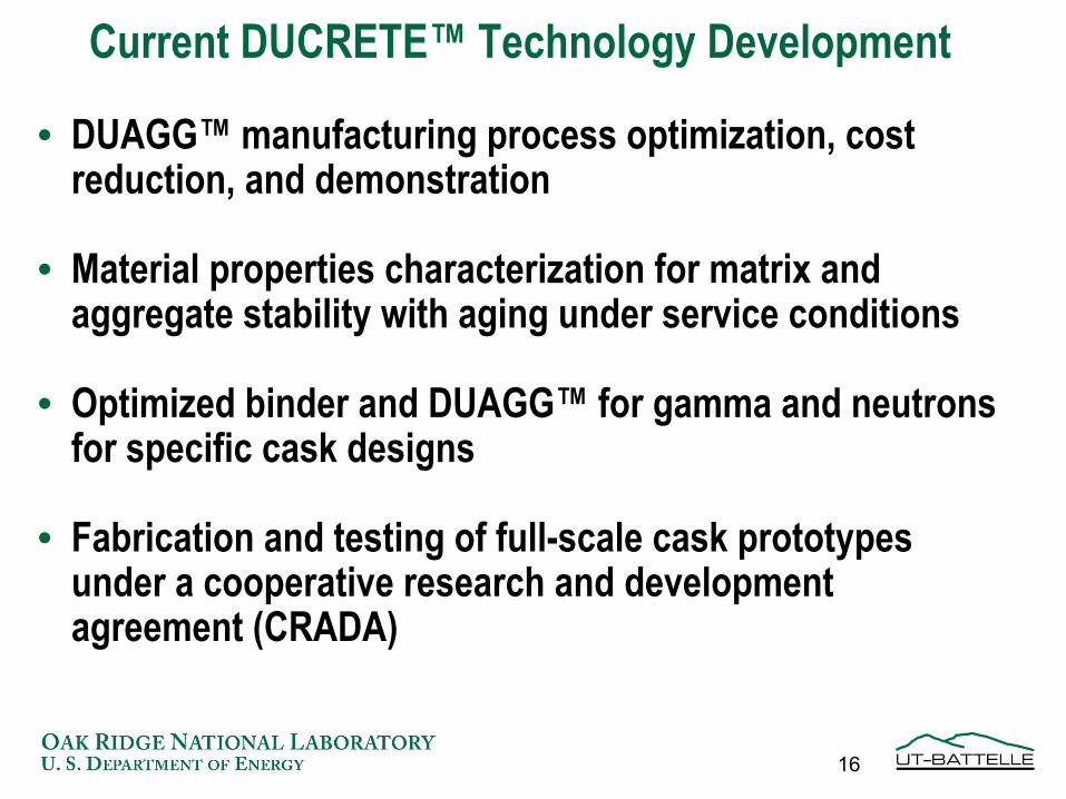
Current DUCRETE™ Technology Development
• DUAGG™ manufacturing process optimization, cost reduction, and demonstration
• Material properties characterization for matrix and aggregate stability with aging under service conditions
• Optimized binder and DUAGG™ for gamma and neutrons for specific cask designs
• Fabrication and testing of full-scale cask prototypes under a cooperative research and development agreement (CRADA)

17
Current Laboratory Studies

18
Current DUAGG™ Exposure Studies Using ASTM C289-94 Standard Test Method
• At a constant surface-to-liquid ratio of 1:10, the sinteredDUAGG™ samples are exposed to – distilled (DI) water– 1 N sodium hydroxide (NaOH) standard solution– saturated water extract of high-alkali cement
• The three exposure temperatures and six time intervals are 25, 66, and 150ºC at intervals of 30, 60, 90, 180, 240, and 360 days

19
Uranium Leached From DUAGG
0.000
0.020
0.040
0.060
0.080
0.100
0.120
0.140
0.160
DI wate
r- 1 m
DI wate
r- 2 m
DI wate
r- 3 m
DI wate
r- 6 m
DI wate
r- 13
mNaO
H - 1 m
NaOH - 2
mNaO
H - 3 m
NaOH - 6
m
NaOH - 1
3 mon
ths
cemen
t sol.
- 1 m
cemen
t sol.
- 2 m
cemen
t sol.
- 3 m
cemen
t sol.
- 6 m
cemen
t sol.
- 13 m
% le
ache
d
20°C
66°C
150°C

20
Aluminum Leached From DUAGG
0
10
20
30
40
50
60
DI wate
r- 1 m
DI wate
r- 2 m
DI wate
r- 3 m
DI wate
r- 6 m
DI wate
r- 13
mNaO
H - 1 m
NaOH - 2
mNaO
H - 3 m
NaOH - 6
m
NaOH - 1
3 mon
ths
cemen
t sol.
- 1 m
cemen
t sol.
- 2 m
cemen
t sol.
- 3 m
cemen
t sol.
- 6 m
cemen
t sol.
- 13 m
% le
ache
d
20°C
66°C
150°C

21
Silicon Leached From DUAGG
0
5
10
15
20
25
30
35
40
45
DI wate
r- 1 m
DI wate
r- 2 m
DI wate
r- 3 m
DI wate
r- 6 m
DI wate
r- 13
mNaO
H - 1 m
NaOH - 2
mNaO
H - 3 m
NaOH - 6
m
NaOH - 1
3 mon
ths
cemen
t sol.
- 1 m
cemen
t sol.
- 2 m
cemen
t sol.
- 3 m
cemen
t sol.
- 6 m
cemen
t sol.
- 13 m
% le
ache
d
20°C
66°C
150°C

22
Comparison of Release Rates for Uranium Obtained with Data from the Literature
•Our work: 0.25 mg/(m2•day) after 1 month at 66°C in DI water~0.40 mg/(m2•day) after 13 monthsin cement pore solution
•Thomas and Till: 5 mg/(m2•day) after 8 days at 70°C in DI water

23
Evaluation of alkali-reaction reaction between DUAGG and the leaching solutions• Because of the glassy nature of DUAGG, it was
suspected that alkali-aggregate reactions could be formed in NaOH or cement pore solutions.
• SEM observations of the DUAGG pellets were made for samples up to 6 months of exposure to verify if such problem was existing.

24
View of DUAGG before testing
Detail of the surface from secondary electrons
A contains AlB contains Ti and some Mg
C are DUO2 particles surrounded by dark basalt
A
B
C
C

25
DUAGG after 6 months in cement pore solution
Covered by CaCO3 and Needle like crystals containing Ca, Si and some Al.67 C secondary electrons
20 m
67C Backscattered electrons50 m
67C secondary electrons
50 m

26
DUAGG after 6 months in cement pore solution
Cement hydration products cover surface with phases with Ca, Si, and Al. 150 C secondary electrons
m2
150 C secondary electrons
10 m
150 C backscattered electrons
10 m

27
Conclusions•After 13 months of exposure the release rate of uranium in a cement pore solution is low and shows that DUAGG is better suited than UO2 for use in concrete applications.
•A protective layer of recrystallization products from the basalt phase of DUAGG appear to cover the surface, slowing down the release of uranium into solution.
•In the cement pore solution, after 6 months of exposure, no deleterious products from alkali-reaction were observed.

28
Conclusions(continued)
• Combinations of gamma-absorbing DU and neutron-absorbing hydrated binders are shown to effectively reduce the size and weight of storage, transport, and disposal casks
• DUCRETE™ will become one of the materials of choice for advanced spent nuclear fuel (SNF) casks
– Requires the demonstration of low-cost fabrication processes
– Requires the demonstration of long-term durability under expected service conditions