Dependable Systems Hardware Dependability - Redundancy · PDF fileDependable Systems Hardware...
38
Dependable Systems Hardware Dependability - Redundancy Dr. Peter Tröger Sources: Siewiorek, Daniel P.; Swarz, Robert S.: Reliable Computer Systems. third. Wellesley, MA : A. K. Peters, Ltd., 1998. , 156881092X Some images (C) Elena Dubrova, ESDLab, Kungl Tekniska Högskolan
Transcript of Dependable Systems Hardware Dependability - Redundancy · PDF fileDependable Systems Hardware...
Dependable Systems
Hardware Dependability - Redundancy
Dr. Peter Tröger
Sources:
Siewiorek, Daniel P.; Swarz, Robert S.: Reliable Computer Systems. third. Wellesley, MA : A. K. Peters, Ltd., 1998. , 156881092X
Some images (C) Elena Dubrova, ESDLab, Kungl Tekniska Högskolan

Dependable Systems | Hardware Redundancy PT 2010
Redundancy (Reiteration)
• Redundancy for error detection and forward error recovery
• Redundancy types: spatial, temporal, informational (presentation, version)
• Redundant not mean identical functionality, just perform the same work
• Static redundancy implements fault masking
• Fault does not show up, since it is transparently removed
• Examples: Voting, correcting codes, N-modular redundancy (NMR), (4-2) concept, special logic, TMR with duplex
• Dynamic redundancy
• After fault detection, the system is reconfigured to avoid a failure
• Examples: Back-up sparing, duplex and share, pair and spare
• Hybrid approaches
2
Dependable Systems | Hardware Redundancy PT 2010
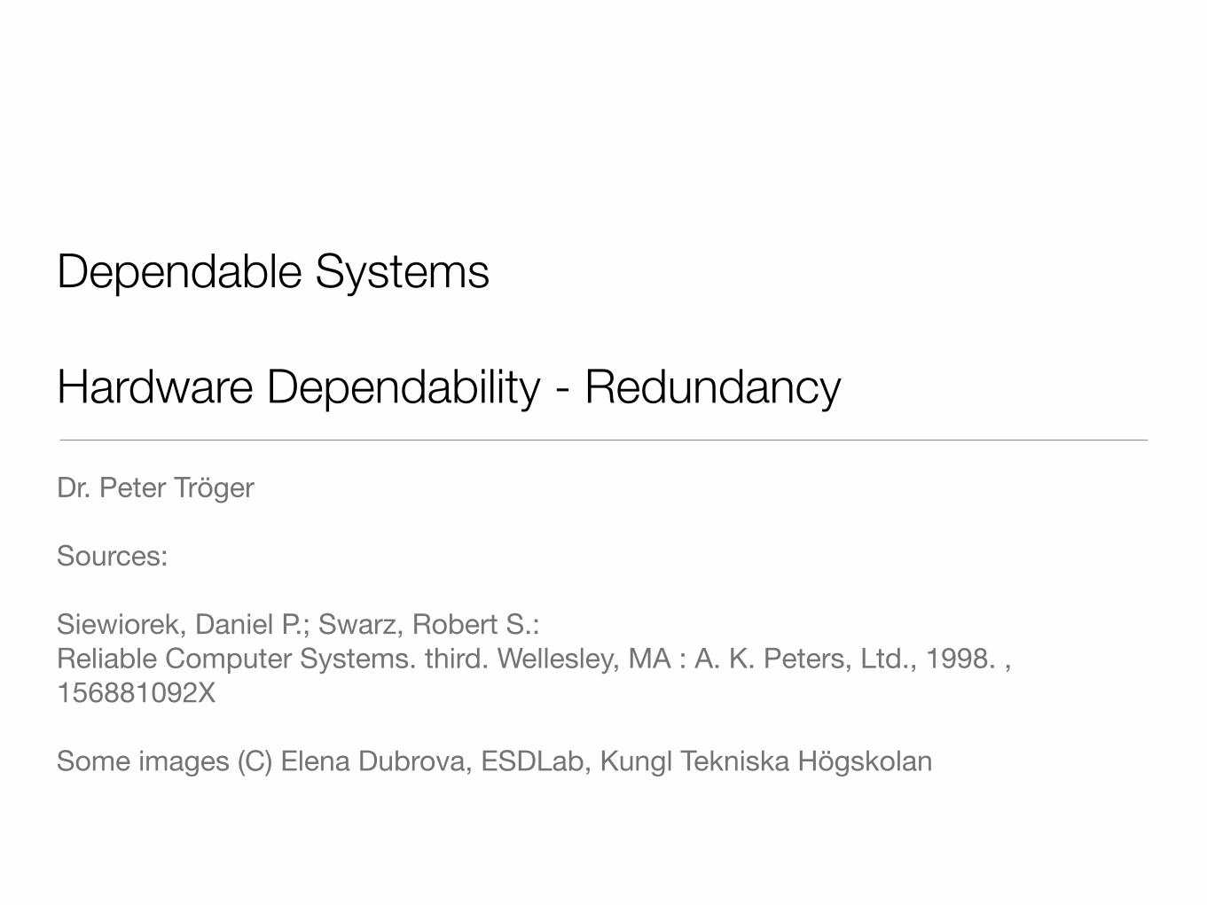
Redundancy
• Redundancy is never for free !
• Hardware: Additional components, area, power, shielding, ...
• Software: Development costs, maintenance costs, ...
• Information: Extra hardware for decoding / encoding
• Time: Faster processing (CPU) to achieve same application performance
• Always demands tradeoff against achievable dependability
3

Dependable Systems | Hardware Redundancy PT 2010
Example: VAX Spatial Hardware Redundancy
4

Dependable Systems | Hardware Redundancy PT 2010
Redundancy Classification (Hitt / Mulcare)
5
Active Redundant Modules
Passive Spare
Modules
Permanent Sync
Deactivated Spare
Component

Dependable Systems | Hardware Redundancy PT 2010
Static Redundancy: N-Modular Redundancy
• Voter gives correct result if the voter is correct and the module majority are correct
• Compare results itself or checksums of it
• Tripe-modular redundancy (TMR): 2 out of 3 modules deliver correct results
• Generalization with N-modular redundancy: N=2m+1
• Standard case without any redundancy is called simplex
6
RTMR = RV ·R2−of−3
= RV (R3M + 3R2
M (1−RM ))
Module 1
Module 2
Module 3 Voter
...
Module N
Input Output
RNMR =m�
i=0
�N
i
�(1−R)iRN−i

Dependable Systems | Hardware Redundancy PT 2010
TMR Reliability
7
0 0,1 0,2 0,3 0,4 0,5 0,6 0,7 0,8 0,9
0,25
0,5
0,75
TMR
Single Module
System Reliability
Module Reliability
• TMR is appropriate if RTMR > RM
• Example with perfect voter - TMR only improves system when RM > 0.5
• Voter must have RV>0.9 for RTMR > RM

Dependable Systems | Hardware Redundancy PT 2010
Hardware Voting
• Base for hardware solution is the 1-bit majority voter
• f=ab + ac + bc
• Delivers bit that has the majority
• Requires 2 gate delays and 4 gates
• Hardware voting can become expensive
• 128 gates and 256 flip-flops for 32-bite voter
8

Dependable Systems | Hardware Redundancy PT 2010
Voting Strategy (Reiteration)
• Exact voting: Only one correct result possible
• Majority vote for uneven module numbers
• Generalized median voting - Select result that is the median, by iteratively removing extremes
• Formalized plurality voting - Divide results in partitions, choose random member from the largest partition
• Inexact voting: Comparison at high level might lead to multiple correct results
• Non-adaptive voting - Use allowable result discrepancy, put boundary on discrepancy minimum or maximum (e.g. 1,4 = 1,3)
• Adaptive voting - Rank results based on past experience with module results
• Compute the correct value based on „trust“ in modules from experience
• Example: Weighted sum R=W1*R1 + W2*R2 + W3*R3 with W1+W2+W3=1
9

• Have relevant modules redundant, switch on detected failure
• Identification on mismatch („test“)
• Self-diagnostics procedure
• Self-checking logic
• Watchdog timer, e.g.components resettingeach other
• Outside arbiter for signaturesor black box tests
• Test interval depends on application scenario - each clock period / bus cycle / ...
• Also called dual-modular redundancy
Dependable Systems | Hardware Redundancy PT 2010
Dynamic Redundancy: Duplex Systems
10
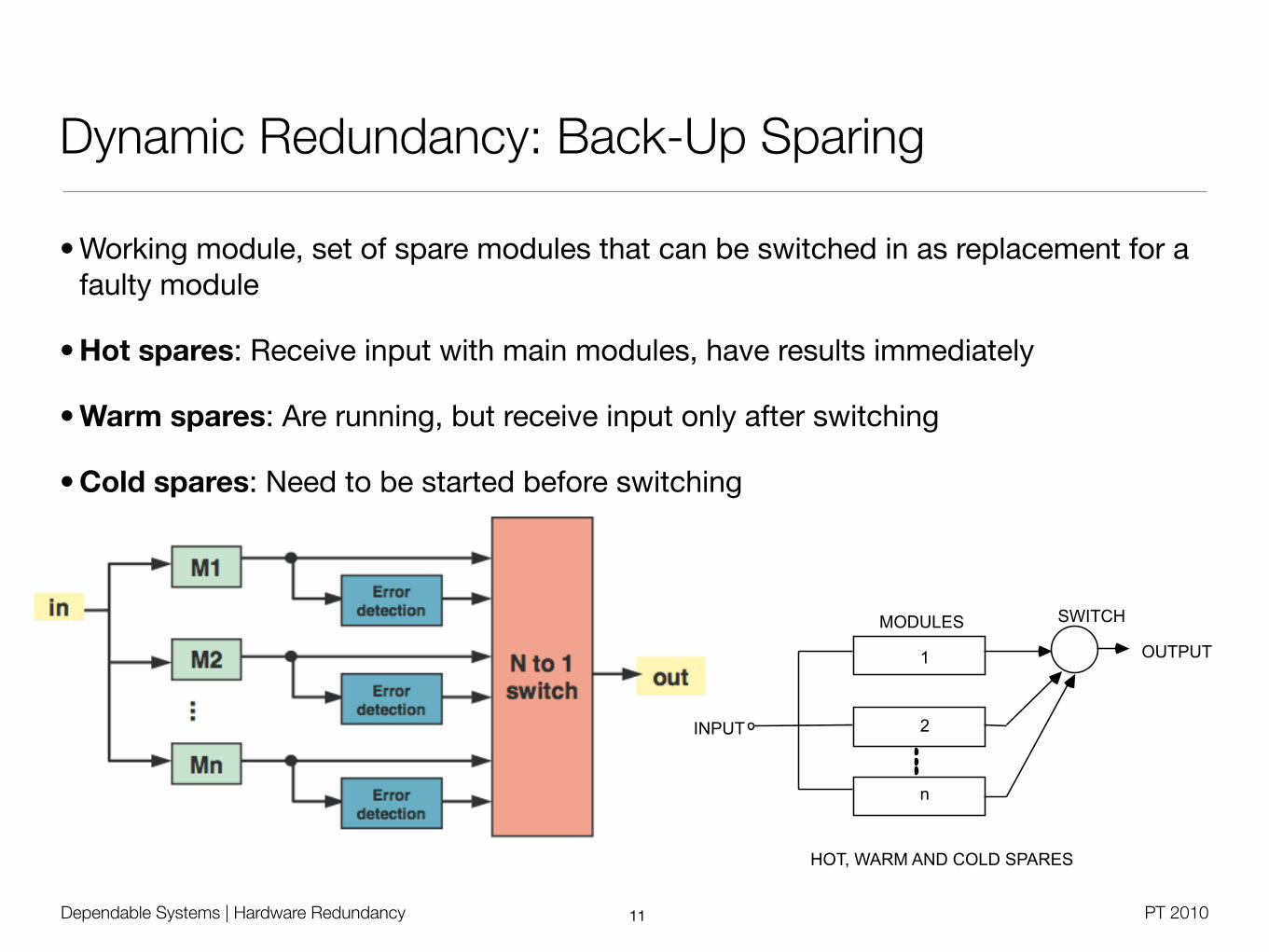
• Working module, set of spare modules that can be switched in as replacement for a faulty module
• Hot spares: Receive input with main modules, have results immediately
• Warm spares: Are running, but receive input only after switching
• Cold spares: Need to be started before switching
Dependable Systems | Hardware Redundancy PT 2010
Dynamic Redundancy: Back-Up Sparing
11
MODULES
1
2
n
SWITCH
OUTPUT
INPUT
HOT, WARM AND COLD SPARES
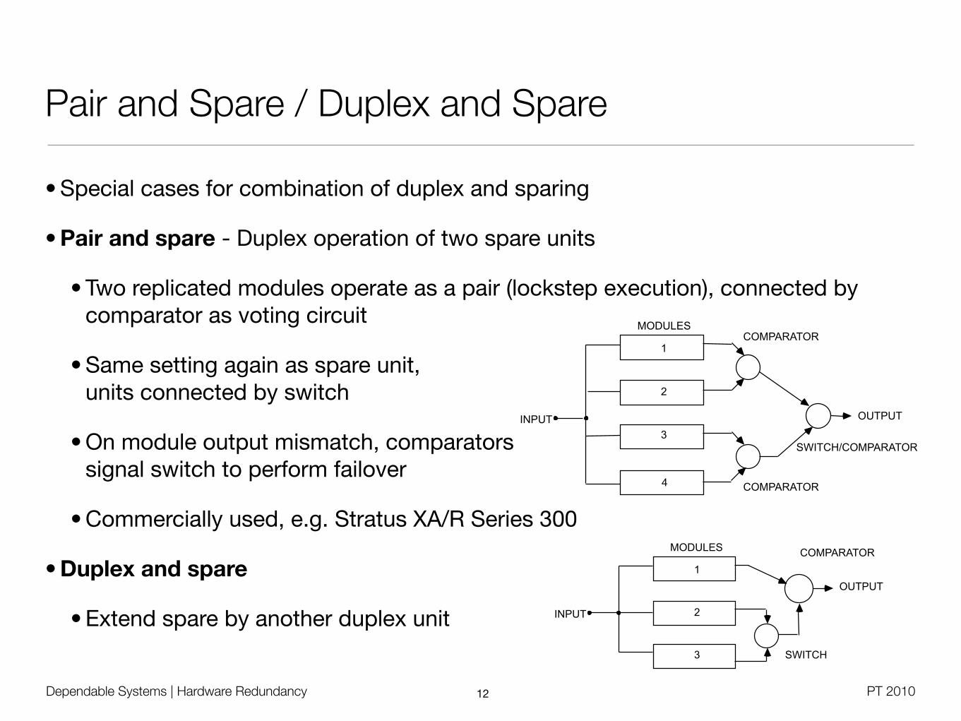
• Special cases for combination of duplex and sparing
• Pair and spare - Duplex operation of two spare units
• Two replicated modules operate as a pair (lockstep execution), connected by comparator as voting circuit
• Same setting again as spare unit, units connected by switch
• On module output mismatch, comparators signal switch to perform failover
• Commercially used, e.g. Stratus XA/R Series 300
• Duplex and spare
• Extend spare by another duplex unit
Dependable Systems | Hardware Redundancy PT 2010
Pair and Spare / Duplex and Spare
12
MODULES
1
2
3
OUTPUT INPUT
COMPARATOR
4 COMPARATOR
SWITCH/COMPARATOR
MODULES
1
2
3
OUTPUT
INPUT
COMPARATOR
SWITCH

Dependable Systems | Hardware Redundancy PT 2010
Hybrid Approaches
• N-modular redundancy with spares
• Also called hybrid redundancy
• System has basic NMR configuration
• Disagreement detector replacesmodules with spares if their output is not matchingthe voting result
• Reliability as long as the spare pool is not exhausted
• Improves fault masking capability of TMR
• Can tolerate 2 faults with one spare, while classic NMR would need 5 modules(with the typical majority voting)
13

Dependable Systems | Hardware Redundancy PT 2010
TMR with Spares
14
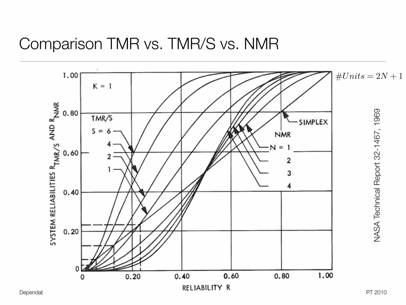
NASA Technical Report 32-1467, 1969
• Basic reliability computation based on similar module failure rate in spares andnon-spares
• At least any two of all modules must survive
RTMR/S = 1− (1−R)S+2[1 +R× (S + 2)]
Dependable Systems | Hardware Redundancy PT 2010
Comparison TMR vs. TMR/S vs. NMR
15
NA
SA
Tec
hnic
al R
epor
t 32-
1467
, 196
9
#Units = 2N + 1

Dependable Systems | Hardware Redundancy PT 2010
Hybrid Approaches
• Self-purging redundancy
• Redundant modules, each can remove itself from the system if faulty
• Basic idea: Test for agreement with the voting result, otherwise 0
16
• Threshold gates are analog circuit elements
• Potentially more reliable than hybrid
Dependable Systems | Hardware Redundancy PT 2010
Hybrid Approaches
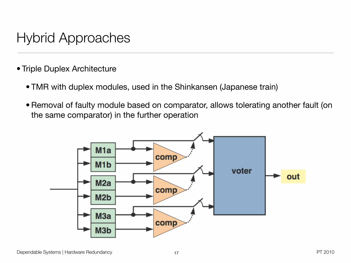
• Triple Duplex Architecture
• TMR with duplex modules, used in the Shinkansen (Japanese train)
• Removal of faulty module based on comparator, allows tolerating another fault (on the same comparator) in the further operation
17

Dependable Systems | Hardware Redundancy PT 2010
The Real World of Hardware Redundancy -Replacement Frequencies [Schroeder 2007]
18
760 node cluster,2300 disks
ISP, multiple sites,26700 disks
ISP, multiple sites,9200 machines,
39000 disks
Dependable Systems | Hardware Redundancy PT 2010
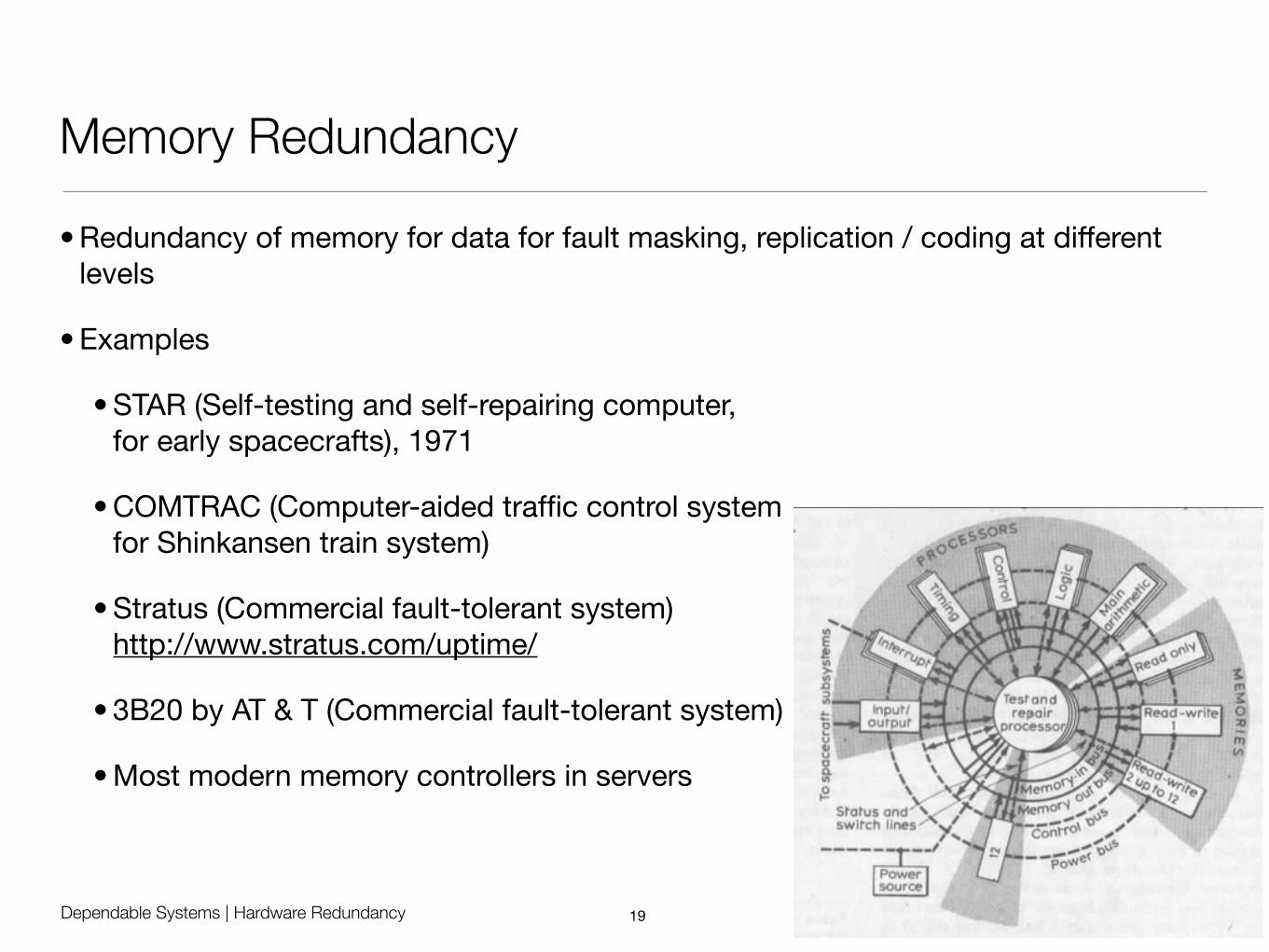
Memory Redundancy
• Redundancy of memory for data for fault masking, replication / coding at different levels
• Examples
• STAR (Self-testing and self-repairing computer, for early spacecrafts), 1971
• COMTRAC (Computer-aided traffic control systemfor Shinkansen train system)
• Stratus (Commercial fault-tolerant system)http://www.stratus.com/uptime/
• 3B20 by AT & T (Commercial fault-tolerant system)
• Most modern memory controllers in servers
19

Dependable Systems | Hardware Redundancy PT 2010
Memory Redundancy
• Standard technology in DRAMs
• Bit-per-byte parity, check on read access - implemented by additional parity memory chip
• ECC with Hamming codes - 7 check bits for 32 bit data words, 8 bit for 64 bit
• Leads to 72 bit data bus between DIMM and chipset
• Computed by memory controller on write, checked on read
• Study by IBM: ECC memory achieves R=0.91 over three years
• Hewlett Packard Advanced ECC (1996)
• Can detect and correct single bit and double bit errors
20
Dependable Systems | Hardware Redundancy PT 2010
Memory Redundancy
• IBM ChipKill
• Originally developed for NASA Pathfinder project
• Corrects up to 4 bit errors, detects up to 8 bit errors
• Implemented in chipset and firmware, works with standard ECC modules
• Based on striping approach with parity checks (similar to RAID)
• 72 bit data word is splitted in 18 bit chunks an distributed on 4 DIMM modules
• Sum of 18 DRAM chips per module, one bit per chip
• HP Hot Plug RAID Memory
• Five memory banks, cache line is striped, fifth bank for parity information
• Corrects single bit, double bit, 4-bit, 8-bit errors; hot plugging support
21
Dependable Systems | Hardware Redundancy PT 2010
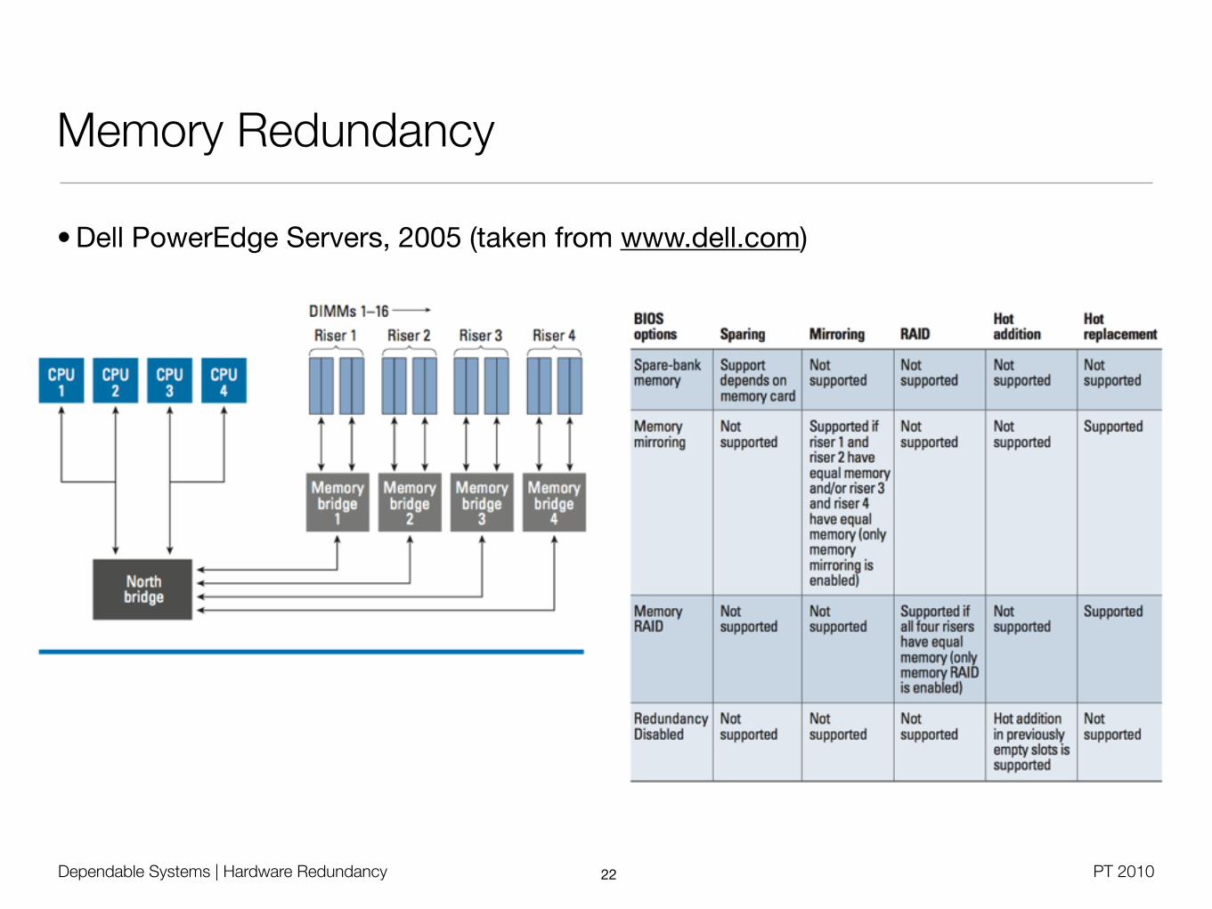
Memory Redundancy
• Dell PowerEdge Servers, 2005 (taken from www.dell.com)
22

Dependable Systems | Hardware Redundancy PT 2010
Memory Redundancy
• Fujitsu System Board D2786 for RX200 S5 (2010)
• Independent Channel Mode: Standard operational module, always use first slot
• Mirrored Channel Mode: Identical modules on slot A/B (CPU1) and D/E (CPU2)
23

Dependable Systems | Hardware Redundancy PT 2010
Disk Redundancy
• Typical measure is the annual failure rate (AFR) - average number of failures / year
• Can be interpreted as failure probability during a year, if AFR < 1
• Disk MTTF: On average, one failure takes place in the given disk hours
• Example: Seagate Barracuda ST3500320AS: MTTF=750000h=85.6 years
• With thousands disk, on average every 750h a disk fails
• Measured by the manufacturer under heavy load and physical stress
• MTTF equals roughly MTBF with these numbers, so AFR=0.012
24
AFR = 1MTBFyears
= 8760MTBFhours
Dependable Systems | Hardware Redundancy PT 2010
RAID
• Redundant Array of Independent Disks (RAID) [Patterson et al. 1988]
• Improve I/O performance and / or reliability by building raid groups
• Replication for information reconstruction on disk failure (degrading)
• Requires computational effort (dedicated controller vs. software)
• Assumes failure independence
25
Dependable Systems | Hardware Redundancy PT 2010
RAID Reliability Comparison
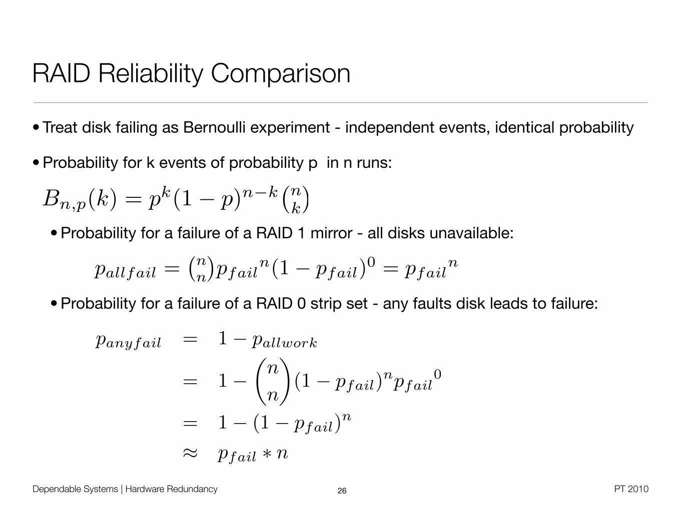
• Treat disk failing as Bernoulli experiment - independent events, identical probability
• Probability for k events of probability p in n runs:
• Probability for a failure of a RAID 1 mirror - all disks unavailable:
• Probability for a failure of a RAID 0 strip set - any faults disk leads to failure:
26
Bn,p(k) = pk(1− p)n−k�n
k
�
pallfail =�nn
�pfailn(1− pfail)0 = pfailn
panyfail = 1− pallwork
= 1−�n
n
�(1− pfail)
npfail0
= 1− (1− pfail)n
≈ pfail ∗ n

• From last slide:
• D - Total number of data disks
• G - Number of data disks in a group (e.g. G=1 in RAID1)
• C - Number of check disks (e.g. parity) in a group (e.g. D=1 in RAID1)
• nG = D / G = number of groups
• Average number of second failures during repair comes again from disk MTTF
Dependable Systems | Hardware Redundancy PT 2010
RAID MTTF Calculation [Patterson]
27
MTTFDiskArray =MTTFDisk
n
MTTFGroup =MTTFDisk
G+ C· 1
pSecondFailureDuringRepair
pSecondFailure =MTTR
MTTFDiskG+C−1
MTTFRaid =MTTFGroup
nG
=MTTFDisk
2
(G+ C) ∗ nG ∗ (G+ C − 1) ∗MTTR

Dependable Systems | Hardware Redundancy PT 2010
RAID 0
• Raid 0 - Block-level striping
• I/O performance improvement with many channels and drives
• One controller per drive
• Optimal stripe size depends on I/O request size, random vs. sequential I/O, concurrent vs. single-threaded I/O
• Fine-grained striping: Good load balancing, catastrophic data loss
• Coarse-grained striping: Good recovery for small files, worser performance
• One option: Strip size = Single-threaded I/O size / number of disks
• Parallel read supported, but positioning overhead for small concurrent accesses
• No fault tolerance
28
(C) Wikipedia
MTTFRaid0 =MTTFDisk
N
Dependable Systems | Hardware Redundancy PT 2010
RAID 1
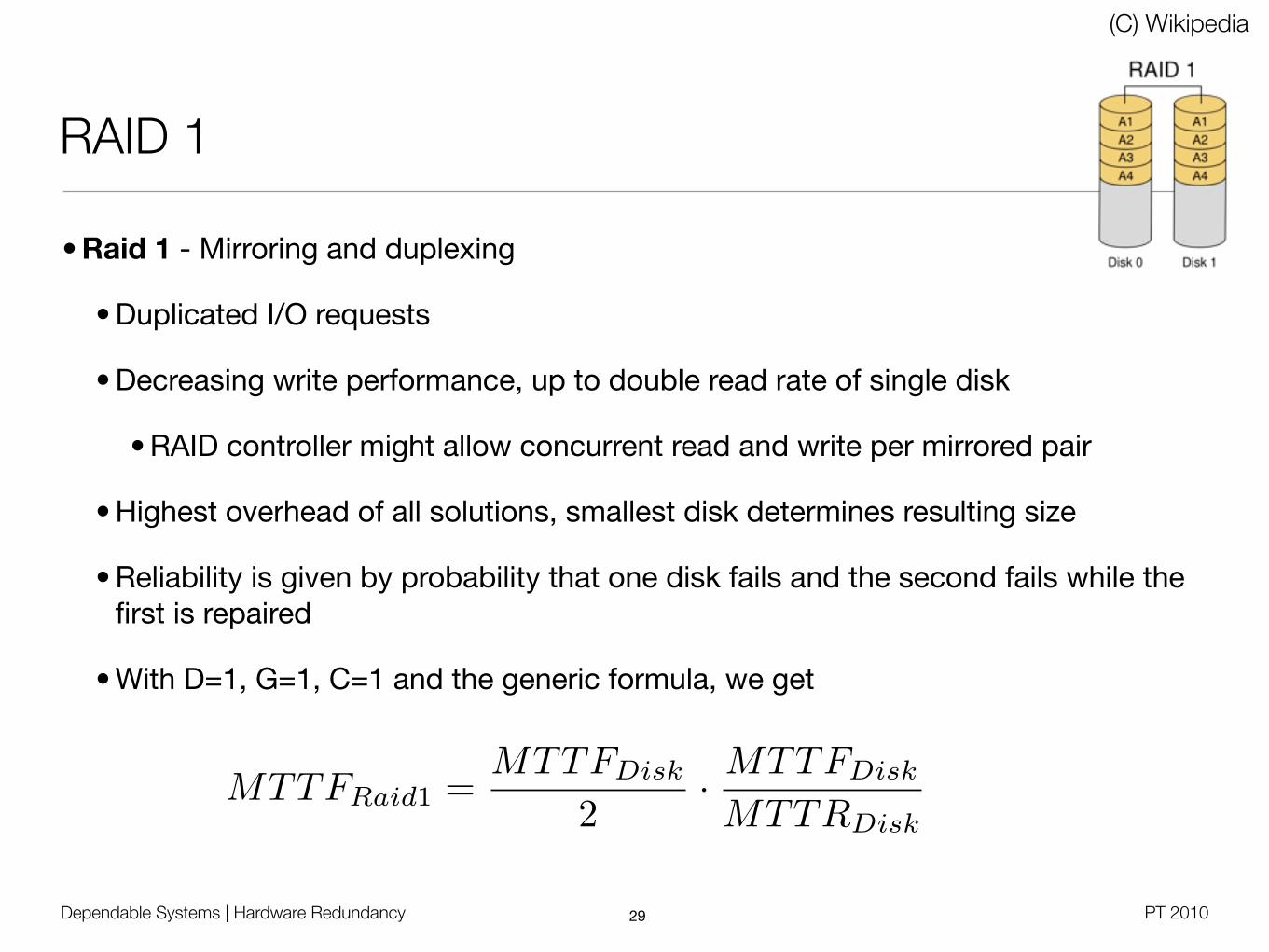
• Raid 1 - Mirroring and duplexing
• Duplicated I/O requests
• Decreasing write performance, up to double read rate of single disk
• RAID controller might allow concurrent read and write per mirrored pair
• Highest overhead of all solutions, smallest disk determines resulting size
• Reliability is given by probability that one disk fails and the second fails while the first is repaired
• With D=1, G=1, C=1 and the generic formula, we get
29
(C) Wikipedia
MTTFRaid1 =MTTFDisk
2· MTTFDisk
MTTRDisk
Dependable Systems | Hardware Redundancy PT 2010
Raid 2/3
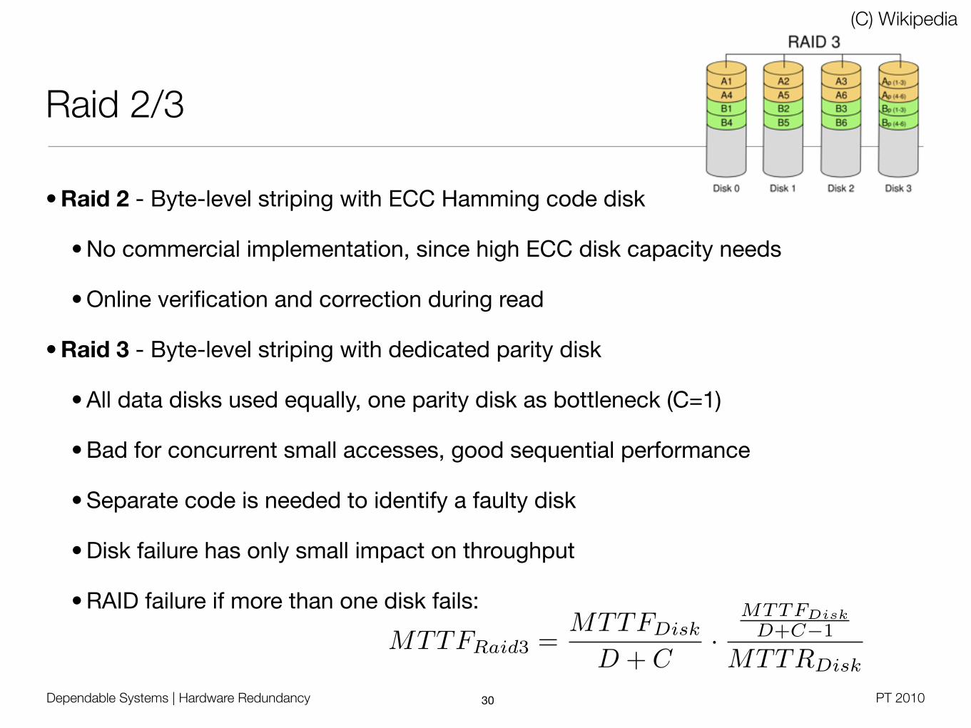
• Raid 2 - Byte-level striping with ECC Hamming code disk
• No commercial implementation, since high ECC disk capacity needs
• Online verification and correction during read
• Raid 3 - Byte-level striping with dedicated parity disk
• All data disks used equally, one parity disk as bottleneck (C=1)
• Bad for concurrent small accesses, good sequential performance
• Separate code is needed to identify a faulty disk
• Disk failure has only small impact on throughput
• RAID failure if more than one disk fails:
30
(C) Wikipedia
MTTFRaid3 =MTTFDisk
D + C·
MTTFDiskD+C−1
MTTRDisk
Dependable Systems | Hardware Redundancy PT 2010
Parity With XOR
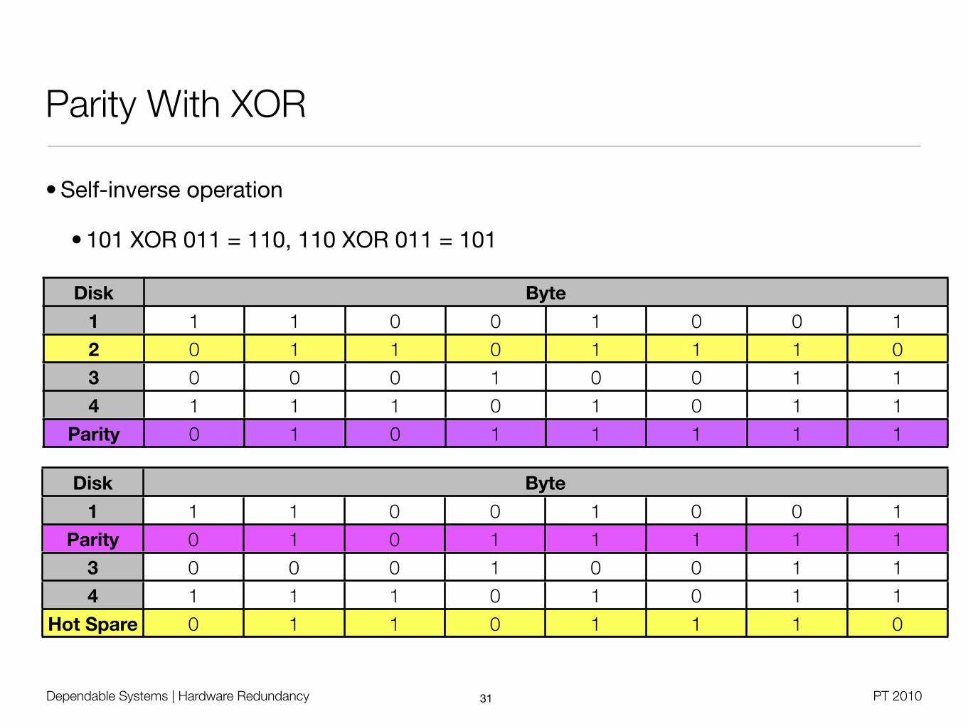
• Self-inverse operation
• 101 XOR 011 = 110, 110 XOR 011 = 101
31
Disk ByteByteByteByteByteByteByteByte
1
2
3
4
Parity
1 1 0 0 1 0 0 1
0 1 1 0 1 1 1 0
0 0 0 1 0 0 1 1
1 1 1 0 1 0 1 1
0 1 0 1 1 1 1 1
Disk ByteByteByteByteByteByteByteByte
1
Parity
3
4
Hot Spare
1 1 0 0 1 0 0 1
0 1 0 1 1 1 1 1
0 0 0 1 0 0 1 1
1 1 1 0 1 0 1 1
0 1 1 0 1 1 1 0

MTTFRaid5 =MTTFDisk
N·
MTTFDiskN−1
MTTRDisk
Dependable Systems | Hardware Redundancy PT 2010
RAID 4 / 5
• Raid 4 - Block-level striping with dedicated parity disk
• RAID 3 vs. RAID 4: Allows concurrent block access
• Raid 5 - Block-level striping with distributed parity
• Balanced load as with Raid 0, but better reliability
• Bad performance for small block writing
• Most complex controller design, difficult rebuild
• When block in a stripe is changed, old block and parity must are read to compute new parity
• For every changed data bit, flip parity bit
32
(C) W
ikip
edia
Dependable Systems | Hardware Redundancy PT 2010
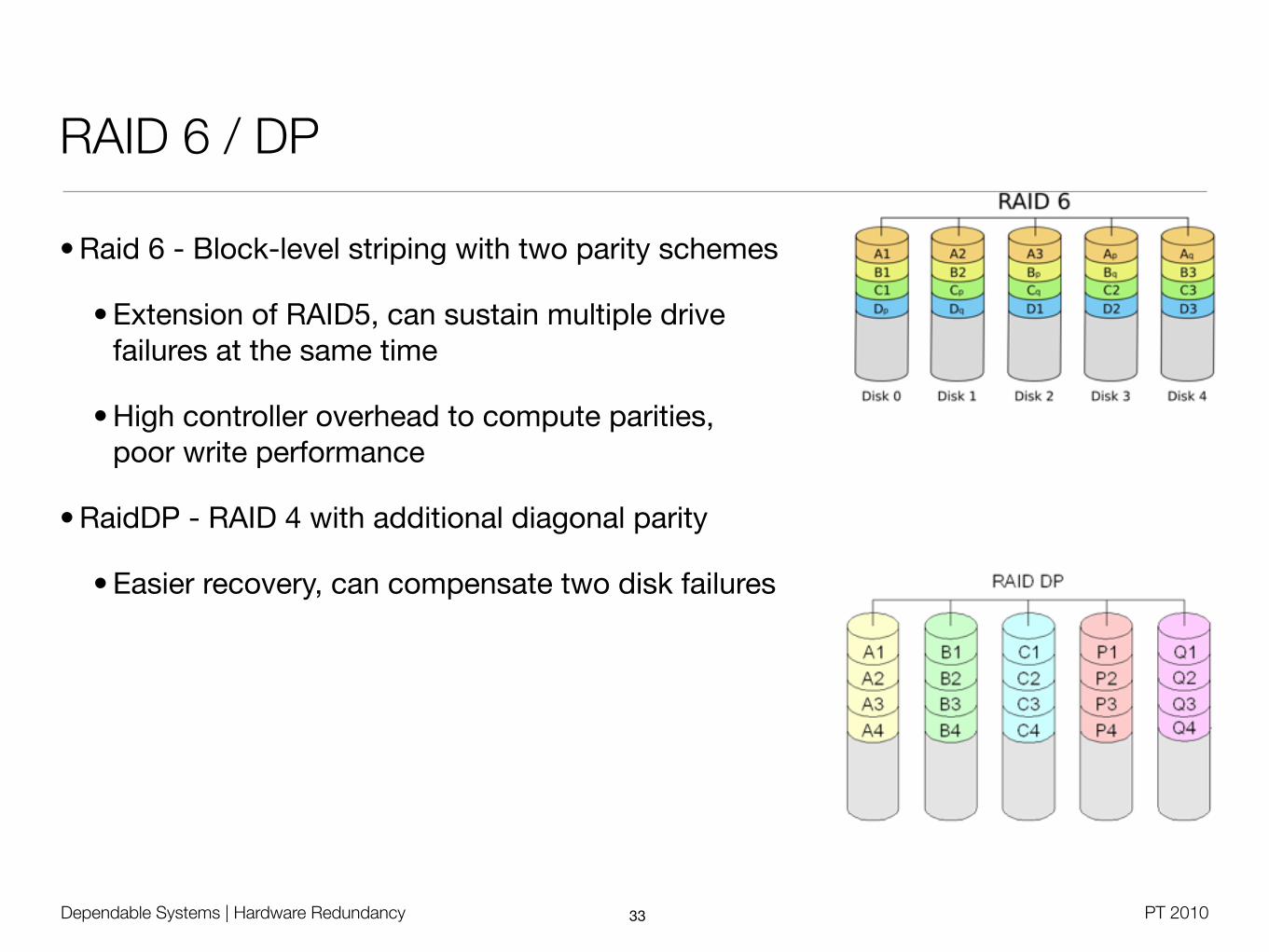
RAID 6 / DP
• Raid 6 - Block-level striping with two parity schemes
• Extension of RAID5, can sustain multiple drivefailures at the same time
• High controller overhead to compute parities,poor write performance
• RaidDP - RAID 4 with additional diagonal parity
• Easier recovery, can compensate two disk failures
33

Dependable Systems | Hardware Redundancy PT 2010
RAID
• Raid 01 - Every mirror is a Raid 0 stripe (min. 4 disks)
• Raid 10 - Every stripe is a Raid 1 mirror (min. 4 disks)
34

Dependable Systems | Hardware Redundancy PT 2010
RAID Analysis (Schmidt)
35
• Take the same number of disksin different constellations
• Ignores resulting capacity,AFRDisk = 0.029, MTTR=8h
• RAID5 has bad reliability, butoffers most effective capacity
• In comparison to RAID5, RAID10can deal with two disk errors
• Also needs to consider different resynchronisation times
• RAID10: Only one disk needs to be copied to the spare
• RAID5 / RAIDDP: All disks must be read to compute parity
• Use RAID01 only in 2+2 combination

Dependable Systems | Hardware Redundancy PT 2010
RAID Analysis (TecChannel.de)
36
RAID 0 RAID 1 RAID 10 RAID 3 RAID 4 RAID 5 RAID 6
Number of drives n > 1 n = 2 n > 3 n > 2 n > 2 n > 2 n > 3
Capacity overhead (%) 0 50 50 100 / n 100 / n 100 / n 200 / n
Parallel reads n 2 n / 2 n - 1 n - 1 n -1 n - 2
Parallel writes n 1 1 1 1 n / 2 n / 3
Maximum read throughput
n 2 n / 2 n - 1 n - 1 n - 1 n - 2
Maximum write throughput
n 1 1 1 1 n / 2 n / 3
Dependable Systems | Hardware Redundancy PT 2010
Software RAID
• Software layer above block-based device driver(s)
• Windows Desktop / Server, Mac OS X, Linux, ...
• Multiple problems
• Computational overhead for RAID levels beside 0 and 1
• Boot process
• Legacy partition formats
• Driver-based RAID
• Standard disk controller with special firmware
• Controller covers boot stage, device driver takes over in protected mode
37

Dependable Systems | Hardware Redundancy PT 2010
Disk Redundancy: Google
• Failure Trends in a Large Disk Drive Population [Pinheiro2007]
• > 100.000 disks for statistical analysis of SMART data
• Failure rates are correlated with drive model, manufacturer and vintage
• Temperature effect only for high end and older drives
• Prediction models based on SMART only work in 56% of the cases
38