
DEPARTMENT OF DEFENCEdtic.mil/dtic/tr/fulltext/u2/a267115.pdf · DEPARTMENT OF DEFENCE DEFENCE...
71
AD-A267 115 ARL-TR-15 AR-007-137 DEPARTMENT OF DEFENCE DEFENCE SCIENCE AND TECHNOLOGY ORGANISATION AERONAUTICAL RESEARCH LABORATORY MELBOURNE, VICTORIA Technical Report 15 HELICOPTER STRUCTURES - A REVIEW OF LOADS, FATIGUE DESIGN TECHNIQUES AND USAGE MONITORING by D.C. LOMBARDO DTIC - NApproved for public release.L E LCT E NJUL Z23 1991n V COMMONWEALTH OF AUSTRALIA 1993 MAY 1993 •7 22 O 6,
-
Upload
hoangkhanh -
Category
Documents
-
view
216 -
download
1
Transcript of DEPARTMENT OF DEFENCEdtic.mil/dtic/tr/fulltext/u2/a267115.pdf · DEPARTMENT OF DEFENCE DEFENCE...
AD-A267 115
ARL-TR-15 AR-007-137
DEPARTMENT OF DEFENCE
DEFENCE SCIENCE AND TECHNOLOGY ORGANISATION
AERONAUTICAL RESEARCH LABORATORY
MELBOURNE, VICTORIA
Technical Report 15
HELICOPTER STRUCTURES - A REVIEW OF LOADS, FATIGUEDESIGN TECHNIQUES AND USAGE MONITORING
by
D.C. LOMBARDO
DTIC- NApproved for public release.L E LCT E
NJUL Z23 1991n
V COMMONWEALTH OF AUSTRALIA 1993
MAY 1993
•7 22 O 6,
Ii
This work Is copyright. Apart from any fair dealing for the purpose ofstudy, research, criticism or review, as permitted under the Copyright Act,no part may be reproduced by any process without written permission.Copyright Is the responsibility of the Director Publishing and Marketing,AGPS. Enquiries should be directed to the Manager, AGPS Press,Australian Government Publishing Service, GPO Box 64, CANBERRA ACT2601.
S~~THE UNIITED STATES NATIONALTECHNICAL INFO FRMArION SERVIC IE
;18 AUTHORISIED TO
h, PRDDU(•,"-: AND SELL THIS8 REPORTiAT
IAR-007-137
DEPARTMENT OF DEFENCEDEFENCE SCIENCE AND TECHNOLOGY ORGANISATION
AERONAUTICAL RESEARCH LABORATORY
Technical Report 15
HELICOPTER STRUCTURES - A REVIEW OF LOADS, FATIGUEDESIGN TECHNIQUES AND USAGE MONITORING
by
D.C. LOMBARDO
SUMMARY
This report is a review of traditional practice with respect to helicopter structural integrity.Aspects covered are: significant fatigue loads for the airframe and rotor system, the methodsused in the fatigue design of current and previous generation rotorcrqfr, fatigue testrequirements, and health and usage monitoring methods.
DSTO4A U ST RALIA
C COMMONWEALTH OF AUSTRALIA 1993
POSTAL ADDRESS: Director, Aeronautical Research Laboratory,506 Lorlmer Street, Fishermens Bend, 3207Victoria, Australia.
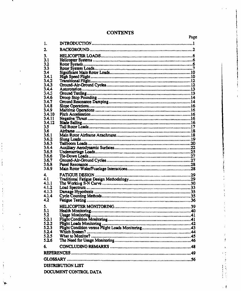
CONTENTSPage
1. INTRODUCTION ...................................................................................... 12. BACKGROUND ...................................................................................... 2
3. HELICOPTER LOADS ............................................................................ 63.1 Helicopter Systems ................................................................................... 63.2 Rotor System .............................................................................................. 63.3 Rotor System Loads ................................................................................. 73.4 Significant M ain Rotor Loads .................................................................. 103.4.1 High Speed Flight ................................................................................... 103.4.2 Transitional Flight .................................................................................. . 123.4.3 Ground-Alr-Ground Cycles ..................................................................... . 123.4.4 Autorotation .................................. . . ...................................... . .. 133.4.5 Ground Taxiing .............................................................................................. 133.4.6 Droop Stop Pounding ............................................................................. . 143.4.7 Ground Resonance Dam ping .................................................................. . 143.4.8 Slope Operations ..................................................................................... . 163.4.9 M aritime Operations ................................................................................ 163.4.10 Pitch Acceleration .................................. 163.4.11 Negative Thrust ............................................................................................. 163.4.12 Blade Sailing .................................................................................................. 163.5 Tail Rotor Loads ............................................................................................ 173.6 irfra e ....................................................................................................... 183.6.1 M ain Rotor Airframe Attachmaent ................................................................... 183.6.2 SlunIg Lo ads .............................................................................................. 193.6.3 Tailboom Loads ............................................................................................. 203.6.4 Auliary Aerodynamic Surfaces ................................. 223.6.5 Undercarriage Loads ................................................................................. 253.6.6 Tie-Down Loads .......................................... 273.6.7 Ground-Air-Ground Cycles .................................................................... . 273.6.8 Panel Resonance ...................................................................................... 283.6.9 M ain Rotor W ake/Fuselage Interactions .................................................. 284. FATIGUE DESIGN ................................................................................ 294.1 Traditional Fatigue Design M ethodology ................................................... 294.1.1 The W orking S-N Curve ......................................................................... 304.1.2 Load Spectrum ........................................................................................ 334.1.3 Damage Hyp•p thesis ................................................................................ 354.1.4 Cycle Counting M ethods ......................................................................... 354.2 Fatigue Testing ........................................................................................ 365. HELICOPTER M ONITORING ............................................................... 395.1 Health M onitoring .................................................................................... 405.2 U"sag M onitorin ............ .................................................... 415.2.1 Flight Condition M onitoring .................................................................... 415.2.2 Flight Loads M onitoring ......................................................................... 425.2.3 Flight Condition versusFlight Loads Monitoring ...................................... 435.2.4 W hich System ? ............................................................................................ 445.2.5 W hat to M onitor? ................................................................................... 455.2.6 The Need for Usage M onitoring ............................................................... 466. CONCLUDING REM ARKS .................................................................... 48
REFERENCES ..................................................................................................... 49
GLOSSARY ................................................................................................................ 56DISTRIBUTION LISTDOCUMENT CONTROL DATA
List of TablesPage
1. Accident rates for fixed-wing and rotary-wing aircraft 42. Listing of helicopter names and type numbers as used in this report 53. Summary of calculated fatigue lives for the hypothetical pitch-link exercise 304. Values for the endurance limit used in the hypothetical pitch-link exercise 32
5. Examples of helicopter missions 33
6. Correlation between airframe fatigue tests and service histories 38
List of FiguresPage
1. Some helicopter configurations 32. The distribution of lift along a rotor blade. 7
3. Variation in lift produced at points on a rotor blade as it sweeps through 3600. 94. Comparison of the first to fifth harmonic components of the lift at blade radial 9
station 97.8 relative to the mean value (harmonic 0).5. Comparison of the lift produced by a rotor blade for two different helicopter 10
flight speeds. Lift is shown only at the 95% blade radial station.6. Typical extent of the rotor disc affected by compressibility effects during high 11
speed flight.7. Rotor disc stalled and reversed flow regions under low and high speed flight 118. Simplified load time history for a helicopter rotor system component, 13
showing the definition of the Ground-Air-Ground (GAG) cycle.9. Movement of the rotor c.g. position as individual rotor blades lead and lag 1510. Engine power requirements versus forward flight speed 18
11. The McDonnell Douglas "Static-Mast" mounting system for the Apache main 19rotor.
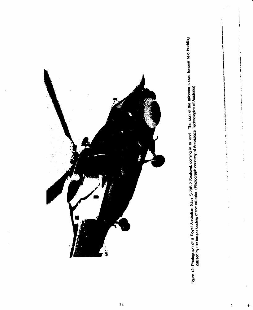
12. Photograph of a Royal Australian Navy S-70B-2 Seahawk coming in to land. 21
13. The NASA Rotor Systems Research Aircraft 2214. Typical locations for tailplanes and stabilators 2315. Russian Mil Mi6 "Hook" helicopter showing the stub wings attached to its 24
fuselage16. Sikorsky UH-60 Black Hawk with ESSS (External Stores Support System) 24
17. The two types of helicopter undercarriages 2518. Landing loads measured in undercarriage oleos for a U.S. Navy helicopter 2619. The safe-life approach to fatigue design 29
20. Derivation of the Mean S-N Curve from test results 3121. Reduction factors used on the mean S-N curve to create a working S-N curve 3222. Various cycle counting methods 37
23. The various categories of helicopter health and usage monitoring 3924. Sequence of events in a flight condition monitoring system. 4225. Sequence of events in a flight loads monitoring system. 42
1. INTRODUCTION
The Aeronautical Research Laboratory (ARL) of Australia's Defence Science andTechnology Organisation (DSTO), has a long history of providing structural integrityjadvice and support to the various services o1 the Austraian Defence Force (ADF), inparticular the Royal Australian Air Force. This support has been mainly concentrated onstructural integrity aspects of the fixed-wing aircraft operated by the ADF. Requests for
spotfor the structural integrity of ADF helicopters have beetr minimal* . This situation
is set to chan since the ADF has recently procured a fleet of 39 Sikorsky S-70A-9 BlackHawk and 1S Sikorsky S-70B-2 Seahawk helicoters. 'The total cost of this procurementis over $1000m and hence it represents a sicantot investment for both the ADF andAustralia. To achieve cost-effective and safe operation of these helicopters during theiroperational life, the ADF will need the type of back-up that ARL has consistently providedfor fixed-wing aircraft.
To provide this support, DSTO needs to acquire in-house knowledge and expertiseconcerning the structural integrity aspects of helcopters. This report is one of the firststeps in acquiring such knowledge and, as such, it is a review of the traditional practice inthe helicopter world as applied to metallic structures, Neither the use of advancedcomposite materials in helicopters nor the use of damage tolerance techniques areaddressed in this report.
The scope of this report can best be summed up in the questions that prompted it:
• What are the fatigue damaging loads experienced by helicopters and in what waysare they different from those experienced by fixed-wing aircraft?
* How have helicopters traditionally been designed for fatigue?
* What components are particularly prone to fatigue failure?
What has been done in the field of helicopter monitoring?
This report has been written so as to be readily understood by those with a knowledge ofboth aircraft and aircraft fatigue. No specialised knowledge of helicopter terminology isrequired as a glossary at the end of this report provides definitions for some of the morecommon terms peculiar to helicopters.
ARL has provided the ADF with help In other amas of helicopter operations such as helicopter flightbehaviour and performance, the maintenance and cat of engines and transmission, human factorelements such a cockpit ergonomics and crew workload, and helicopter accident investigations.
2. BACKGROUND
There are many different configurations possible for helicopters, or rotary-win$ aircraft asthey are also known, (see Fig. 1, next page), but by far the most common is the t thatuses a single main rotor for lift and propulsion and a tall rotor to providc an anti-torqueforce (Fig. l(a)). The term "rotary-wing aircraft" implies that such aircraft have rotatingwings to generate liftM unlike other aircraft that have wings rigidly fixed to their fuselages.Individually known as rotor blades, collectively as a rotor, it is these rota-ini wi thatgive helicopters both their versatility and a susceptibility to fatigue iz'nhlems ulat $s verydifferent to that found in the world of fixed-wing aircraft.
The question might well be asked, "Both helicopters and fixed-wing aircraft are heavier-than-air flying machines, with all which that entails, so why is helicopter fatigue aadstructural integrity so different from the fatigue of fixed-wing aircraft?". The answer liesin the fact that the generation of lift via rotors rather than fixed wings produces a loadingenvironment that is ruled by large dynamic loads that are applied at a high rate. In fact, ithas been suggested, perhaps unkindly, but with some truth, that the easiest way to performfatigue tests on helicopter components is to install them on a helicopter and let it apply thefatigue loads.
At the heart of a helicopter, both physically aid in terms of fatigue problems, lie theengines, transmissions, drivetrain, and rotors. These, in themselves, consist of a multitudeof components that are highly loaded both in the magnitudes of the applied loads and thenumber of applied cycles. The failure of any one of these components can be, and often is,catastrophic, as distinct from fixed-wing aircraft where the number of critical componentsis less and structural redundancy is easier to build in. A survey of serious accidentsinvolving fixed and rotary wing aircraft1. that occurred in the period 1927 to 1981 lists atotal of 1466 accidents for fixed-wing aircraft and 419 for rotary-wing. If the data prior to1964, as well as all military data, are ignored" then the numbers become 1191 and 354respectively. To put this into perspective, it is useful to compare the number of accidents,and resulting fatalities, against the number of aircraft in the world during those years (seeTable 1, page 4). As can be seen, helicopters suffer a proportionately greater number ofaccidents and fatalities than fixed-wing aircraft. Torkington3 highlights this samedifference regarding civil aircraft in Australia. There are, of course, other factors apartfrom the number of aircraft to be taken into account when comparing accident data such asthe number of flights or hours flown, or the types of missions performed. However, evenwhen such factors are included, helicopters still come out worse 4.
The breakdown of fatigue-related accidents listed in the ab ,ve mentioned survey is:structural 57% (rotors 37%, fuselage 8%, landin gear 3%, i.ight controls 9%), enginesand transmissions 32%, and other causes 11%. In terms of fatigue therefore, rotors,engines, and transmissions are the areas which experience the majority of fatigue failures inhelicopters and consequently most of the research is concentrated in these three areas.
Throughout this report, several helicopter types are used to illustrate various points. Forsimplicity, they are mostly referred to by their names or type designations (e.g. AH-64, SeaKing, Black Hawk). Table 2 contains an explanation of the names and type numbers usedin this report. For further information the reader is referred to books which dealspecifically with helicopters and their historys.6.7,8.
"In the survey, it is stated that the data pior to the ya around the mid-sixties an far fromcompreenshe. As well, only a few military services responded to the requests of the survey's authorsfor infrmtion.
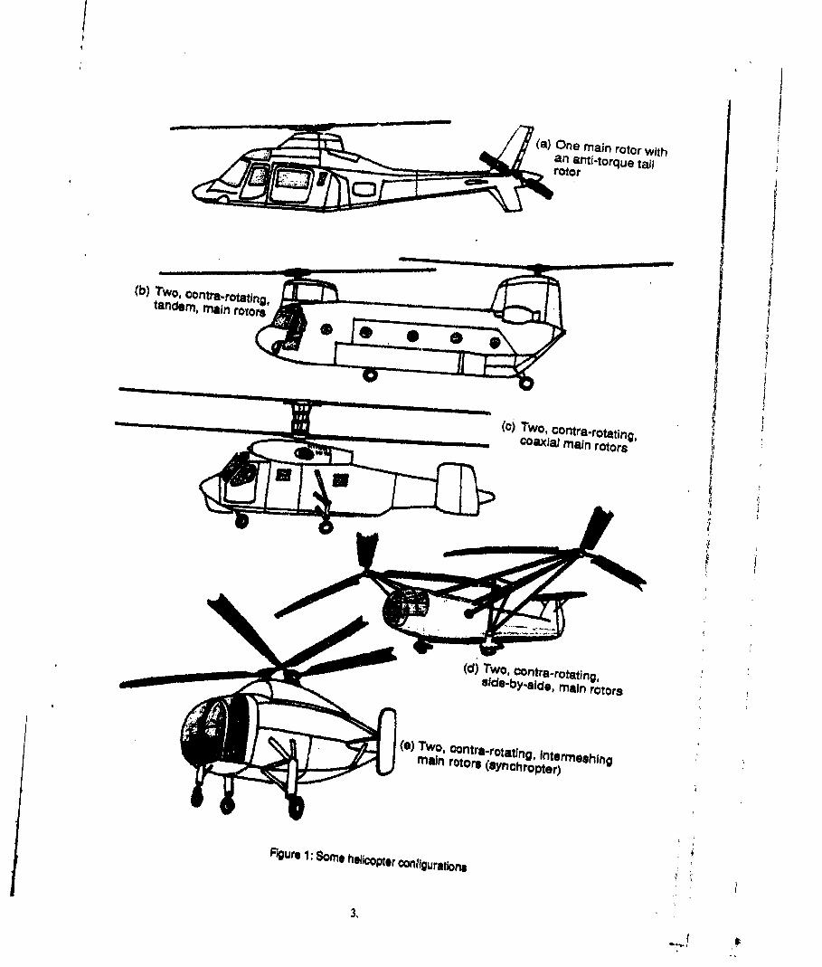
(a) One main rotor withan anti-torque tapl
(b) TWO, oontra.rotatino,tandem, main rotors
c)Two, contra-rotating,
Figure 1 Some h~lcopter 0onlhiguratlbns
3,
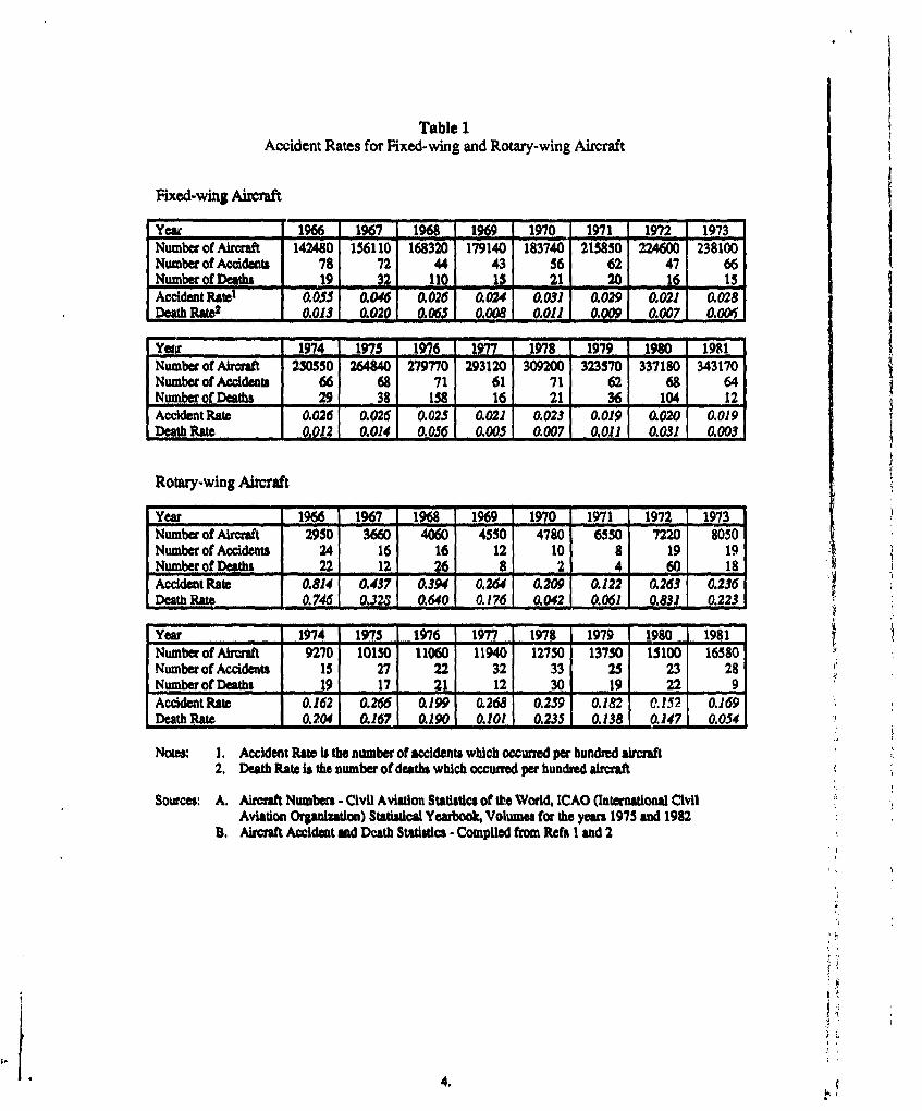
Table 1Accident Rates for Fixed-wing and Rotary-wing Aircraft
Fixed-wing Aircraft
Yea 1966 I1967 1968 1969 1970 1971 1972 1973Numberof Aircraft 142480 156110 168320 179140 183740 215850 224600 238100Number of Acidents 78 72 44 43 56 62 47 66Number of Deadts 19 15 1 21 2 16 15Accident Rate' 0.055 0.046 0.026 0.024 0.031 0.029 0.021 0.028Death R90 e 0.13 1 0. 20 1 0.00• OO8 L 0.0111 0.2&j 1 0.007 1 a.06
Yewr 1974 1975 196 197 1978 1979 1980 1981Number of Aircraft 250550 264840 279770 293120 309200 323570 337180 343170Number of Accidents 66 68 71 61 71 62 68 64Number of Deaths 29 38 158 16 21 36 104 12Accident Rate 0.026 0.026 0.025 0.021 0.023 0.019 0.02O 0.019Death Rate 1 0.0121 0.0141 0.0561 0.0051 0.0071 0.011 0.031 0.0031
Rotary-wing Aircraft
Year 1966 1967 19 1%969 1970 1971 1972 1973Number of Aircraft 2950 3660 4060 4550 4780 6550 7220 8050Number of Accidents 24 16 16 12 10 8 19 19Number of Deaths 22 12 26 8 2 4 60 18Accident Rate 0.814 0.437 0.394 0.264 0.209 0.122 0.263 0.236Death Rate 0.746 0.321 0.6401 .1761 0.42 0.061 0.831 0.2231
Year 1974 1975 1976 1977 1978 1979 1980 1981Number of Aircraft 9270 10150 11060 11940 12750 13750 15100 16580Number of Accidents 15 27 22 32 33 25 23 28Number of Deaths 19 17 21 12 30 , 19 ,, 22 9Accident Rate 0.162 0.266 0.199 0.268 0.259 0.182 0.152 0.169
Death Rate 0.204 0.167 0.190 0.101 0.235 0.138 0.147 0.054
Notes: I. Accident Rate is the number of accidents which occurred per hundred aircraft2. Death Rate is the number of deaths which occurred per hundred aircraft
Sources: A. Aircraft Numbers - Civil Aviation Statistics of the World, ICAO (International CivilAviation Organization) Statistical Yearbook, Volumes for the years 1975 and 1982
B. Aircraft Accident and Death Statistics - Compiled from Refs I and 2
4.
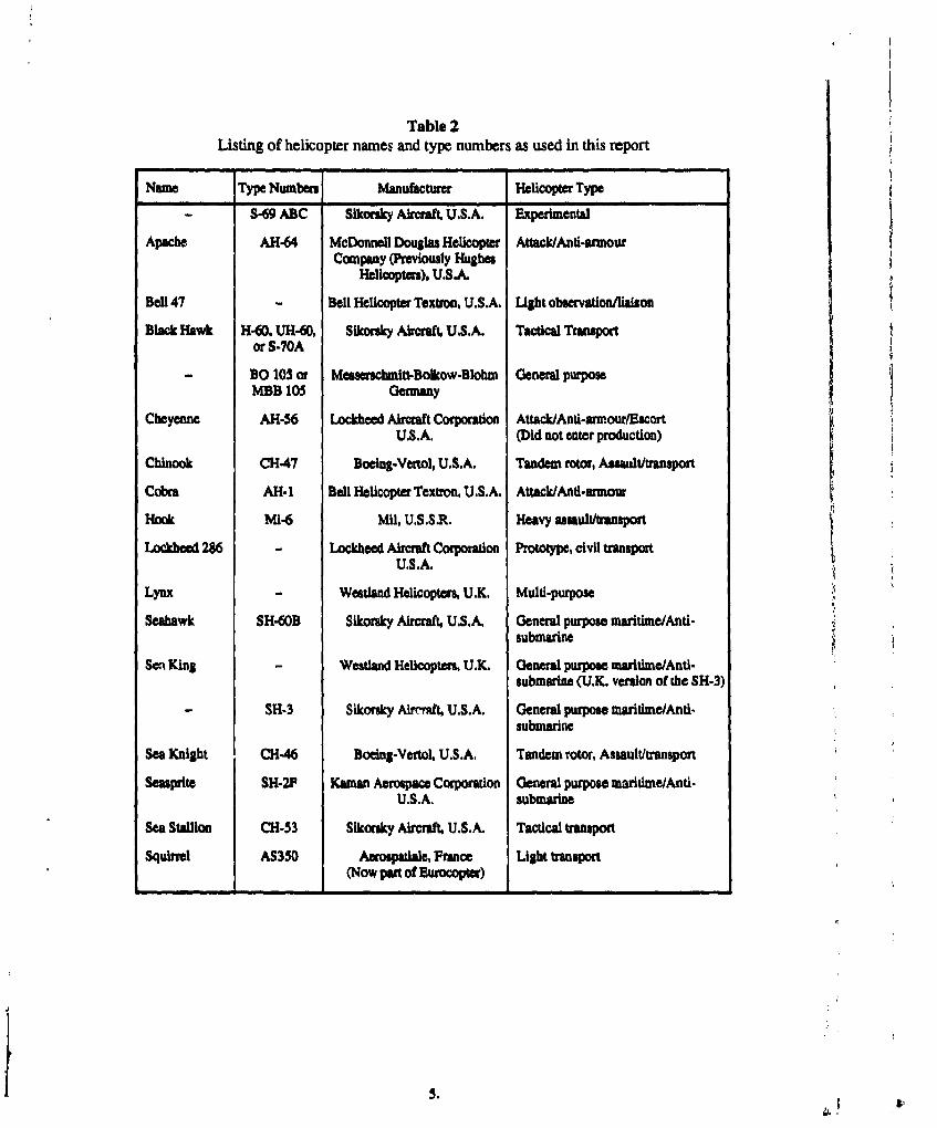
Table 2Listing of helicopter names and type numbers as used in this report
Name Type Numbers Manufacturer Helicopter Type
- -69 ABC Sikorsky Aircraft U.S.A. Experimental
Apache AH-64 McDonnell Douglas Helicopter Attack/Anti-armourCompany (Previously Hughes
Helicopters), U.S.A.
Bell 47 Bell Helicopter Textron, U.S.A. Light observation/liaison
Black Hawk H-60, UH-60, Sikorsky Aircraft, U.S.A. Tactical Transportor S-70A
BO 105 or Messesclnitt-Bolkow-Blohm General purposeMIBB 105 Germany
Cheyenne AH-56 Lockheed Aircraft Corporation Attack/Anti-armour/EscortU.S.A. (Did not enter production)
Chinook CH-47 Boelng-Vertol, U.S.A. Tandem rotor, Assault/transport
Cobra AH.- Bell Helicopter Textron, U.S.A. Attack/Anti-armour
Hook MI-6 MU, U.S.S.R. Heavy assault/transport
Lockhee 286 Lockheed Aircraft Corporation Prototype, civil transportU.S.A. ,
Lynx Westland Helicopters, U.K. Multi-purpose
Seahawk SH-60B Sikorsky Aircraft, U.S.A. General purpose maritime/Anti-submarine
Sea King Westland Helicopters, U.K. General purpose maritime/Anti-submarine (U.K. version of the SH-3)
SH-3 Sikorsky Airerft, U.S.A. General purpose maritime/Anti-submarine
Sea Knight CH-46 Boelng-Vertol, U.S.A. Tandem rotor, Assault/transport
Seasprite SH-2F Kaman Aerospace Corporation General purpose maritime/Anti.U.S.A. submarine
Sea Stalion CH-53 Sikorsky Aircraft, U.S.A. Tactical transport
Squiel AS350 Aerospatiale, France Light transport(Now pan of )urocopw)
5.
3. HELICO:'TER LOADS
The loading environment to which helicopters are subjected differs markedly from that offixed-wing aircraft. Hence, before proceeding with a discussion of the various loadingactions on a helicopter, the two most important differences between helicopters and fixed-wing aircraft should be stated.
Considering the case of steady flight (a condition in w'aich nearly all aircraft spendmost of their time), the loads on a fixed-wing aircraft are essentially static in nature.On the other hand, helicopters experience a complex loading that is both dynamicand highly vibratory. 10o.'1 12,13. This is the case in all flight conditions for ahelicopter other than vertical flight in still air, where it applies to a lesser extent.
* Unlike fixed-wing aircraft, the time spent in a flight condition is as important as thecondition itselP4,15. In other words, "... whereas on a fixed wing aircraft onemanoeuvre goes with one incremental load, a manoeuvre of a helicopter results ina wtmkgr of incremental load cycles * (de Tongeg). Th1is time dependence is theresult of the cyclical loading produced by a rotor blade as it rotates during flight.
3.1 HELICOPTER SYSTEMSIn discussions on helicopter loading, it is generally convenient to divide the helicopter upinto its major system. Following the example of Fraser"6, these systems are:
1. Engines2. Mechanical drive system (gearbox, transmission shafts etc)
3. Rotor system (main and tail)
4. Flight control system5. Airframe (fuselage, tailboom, undercarriage, auxiliary aerodynamic surfaces)
Items 1 and 2 are not within the scope of this report (which is concerned with structuralintegrity) and so will not be discussed here. Item 4, the flight control system is hereconsidered to consist of all the non-rotating mechanical links between the pilot controlsand the control surfaces, both rotating (rotor blades) and non-rotating (fins). As theelements of the control system transmit rather than generate loads they will not beconsidered in this section. The remaining two items will now be considered.
3.2 ROTOR SYSTEM
The rotor system is what gives helicopters their versatility, that is, their ability to take offand land vertically, to hover, and to fly sideways or rearwards. This versatility though,comes at a price, that being that the rotor system is an "... extremely complex dynamicsystem of rotating blades with fundamental and higher order vibratory response, complexunsteady aerodynamics verging upon aeroelastic instabilities and blade stall phenomena
'12
Consider also the following two quotations:(a) "Unlike the relatively well established science of load prediction for fixed wing
aircraft, the helicopter load prediction techniques are still in their infancy ... [thedesigner] simply must determine, or at least confirm, all loads by experimental flightloads surveys.", Crichlow et al' 2, (1967)
(b) "... rotor blade loadings are difficult to accurately predict: all current airworthinessrequirements specify that fatigue analyses must be based on measred loadis.de Jonge9, (1986).
6.
Although separated by almost twenty years, the complexity of the problem has evidentlyallowed little progress to be made in rotor blade load predictions. This is confirmed by arecent study'7 in which four "state-of-the-art" rotor load prediction programs werecompared with each other and against flight data. The results are not very encouraging tothose used to similar fixed-wing studies.
The rotor system has been defined"s as including the rotor blades, hubs, hub-to-bladeattachments, dampers, rotating control system elements and any rotating anti-vibrationfeatures, As already explained in the Background section of this report, the rotor systemcan consist of many different configurations: a main and tail rotor combination or a twinmain rotor combination for example. Although the discussion that follows refersspecifically to helicopters of the main and tail rotor type, it is applicable to the otherconfigurations as well
3.3 ROTOR SYSTEM LOADS
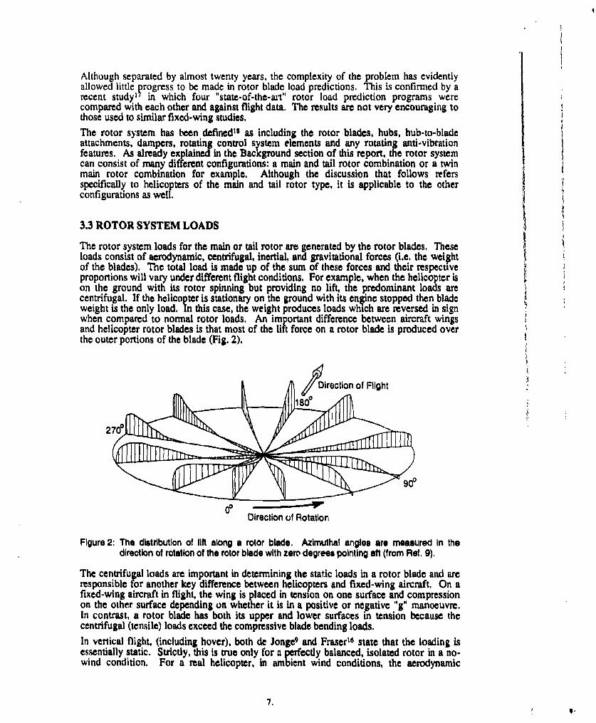
The rotor system loads for the main or tail rotor are generated by the rotor blades. Theseloads consist of aerodynamic, centrifugal, inertial, and gravitational forces (i.e. the weightof the blades). The total load is made up of the sum of these forces and their respectiveproportions will vary under different flight conditions. For example, when the helicopter ison the ground with its rotor spinning but providing no lift, the predominant loads arecentrifugal. If the helicopter is stationary on the ground with its enine stopped then bladeweight is the only load. In this case, the weight produces loads which are reversed in signwhen compared to normal rotor loads. An important difference between aircraft wingsand helicopter rotor blades is that most of the lift force on a rotor blade is produced overthe outer portions of the blade (Fig. 2).
A Direction of Flight
27 ..*0
Direction of Rotation
Figure 2: The distribution of lift along a rotor blade. Azimuthal angles are measured in thedirection of rotation of the rotor blade with zero degrees pointing aft (from Ref, 9).
The centrifugal loads are important in determining the static loads in a rotor blade and areresponsible for another key difference between helicopters and fixed-wing aircraft. On afixed-wing aircraft in flight, the wing is placed in tension on one surface and compressionon the other surface depending on whether it is in a positive or negative "g" manoeuvre.In contrast, a rotor blade has both its upper and lower surfaces in tension because thecentrifugal (tensile) loads exceed the compressive blade bending loads.In vertical flight, (including hover), both de Jonge' and Fraser' 6 state that the loading isessentially static. Strictly, this is true only for a perfectly balanced, isolated rotor in a no-wind condition. For a real helicopter, in ambient wind conditions, the aerodynamic
7, IS,
interaction between the main rotor and the fuselage 19.20,21, and the interaction between themain and tail rotors, will produce unsteady loads in the rotor blades. As well, most tailrotors are mounted such that they produce rolling moments which must be counteractedby the main rotor thrust leading again to unsteady maui rotor blade loads For helicopterswith two main rotors, account must be taken of the interaction between the two rotors,The importance of these loads depends on the geometry of the helicopter fuselage, thespacing between the fuselage, the main rotor and tail rotor, and the strength of the ambientwind. In some cases, these unsteady loads can be significant in terms of fatigue damage.
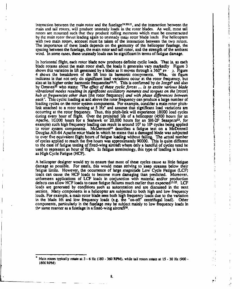
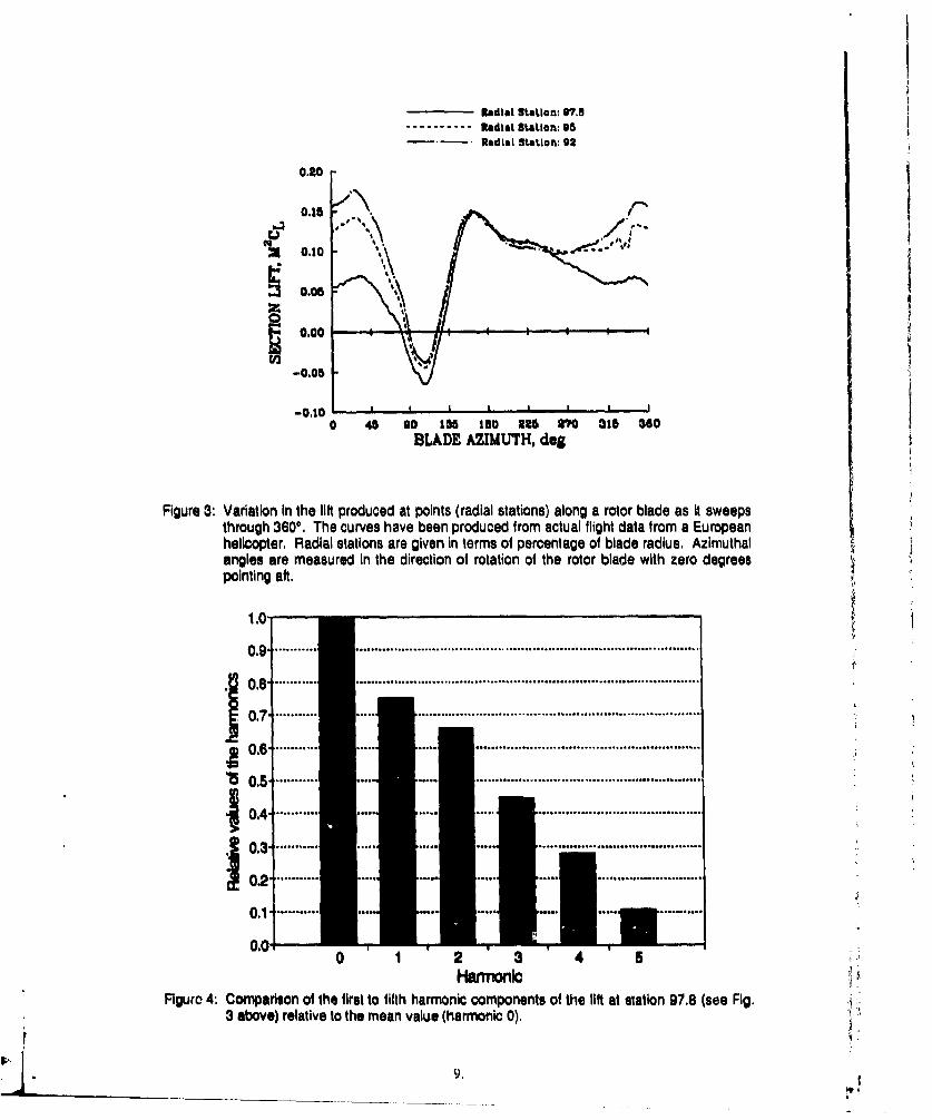
In horizontal flight, each rotor blade now produces definite cyclic loads. That is, as eachblade rotates about the main rotor shaft, the loads it generates vary markedly Figure 3shows this variation in lift generated by a blade as it moves through a 3600 sv ,). Figure4 shows the breakdown of the lift into its harmonic components. Wha, As figureindicates is that not only do significant load variations occur at the rotor frequency, butalso at its higher order harmonic frequencies 32.72. This is confirmed by de Jonge9 and alsoby Greaves 22 who states: "The effect of these cyclic forces ... is to excite various bladevibrational modes resulting in sign~flcant oscillatory moments and torques on the [rotor]hub at frequencies other than [the rotor frequency] and with phase d(iferences betweeneach". This cyclic loading at and above the rotor frequency can produce a large number ofloading cycles on the rotor system components. For example, consider a main rotor pitch-link attached to a rotor turning at 5 Hz and assume that significant load variations areoccurring at the rotor frequency. Thus, this pitch-link will experience 18000 load cyclesduring every hour of flight. Over the projected life of a helicopter (4500 hours for anApache, IC,000 hours for a Seahawk or 20,000 hours for an SH-2F Seas prite23, forexample) such high frequency loading can result in around 107 to 108 cycles being appliedto rotor system components, McDermott2 4 describes a fatigue test on a McDonnellDouglas AH-64 Apache rotor blade in which he states that a damaged blade was subjectedto over five equivalent flight hours of fatigue loading without failing. The ictual numberof cycles applied to reach the five hours was approximately 90000. This is quite differentto the case of fatigue testing of fixed-wing aircraft where only a handful of cycles need beused to represent an hour of flight. In fatigue terminology, this type of loading is knownas High Cycle Fatigue (HCF).
A helicopter designer would try to ensure that most of these cycles cause as little fatiguedamage as possible. For steels, this would mean striving to keep stresses below theirfatigue limits. However, the occurrence of large magnitude Low Cycle Fatigue (LCF)loads can cause the HCF loads to become more damaging than predicted. Moreover,unforeseen applications of LCF loads in conjunction with material and/or productiondefects can allow HCF loads to cause fatigue failures much earlier than expected13,25. LCFloads are generated by conditions such as autorotation and are discussed in the nextsection. Many components in a helicopter are subjected to both high and low frequencyloads. For example, a main rotor blade sees both high frequency loads due to the variationin the blade lift and low frequency loads (e.g. the "on-off' centrifugal load). Othercomponents, particularly in the fuselage may be subject mainly to low frequency loads inth' same manner as a fuselage in a fixed-wing aircraft2 6.
* Main rotors typically rotate at 3 - 6 Hz (180 - 360 RPM), while tall rotors rotate at 15 - 30 Hz (900 -
1800 RPM)
Radial Station: '7.A----------. Radial StaiLon: 95
Radial SatIon: 92
0.20
0.05
0.00
-0.05
-0.10 ' , t i
0 45 so lad tos urn 70 ai1 aceBLADE AZIMUTH, dog
Figure 3: Variation in the lift produced at points (radial stations) along a rotor blade as it sweepsthrough 3600. The curves have been produced from actual flight data from a Europeanhelicopter, Radial stations are given in terms of percentage of blade radius, Azimuthalangles are measured in the direction of rotation of the rotor blade with zero degreespointing aft.
1.0-
0.9* ...... .. . o.6.o.. o............................ o, .... ,.....o... ... ... ..... *.... .... =.............
0.7 . ...... ..... ..........................................................................
0.6 ., ......... o.*=o,****= ...................... ........................
15 0.5 ..... ... .. .. . . ...........................................................
0 . ........ . . . . ....................0.8 .... .... ........... .....
0.00 1 2 3 4 5
Figure 4: Comparison of the first to fifth harmonic components of the lift at station 97.8 (see Fig.3 above) relative to the mean value (harmonic 0), 4:j 03
• 90.2
0.1,-.
3.4 SIGNIFICANT MAIN ROTOR LOADS
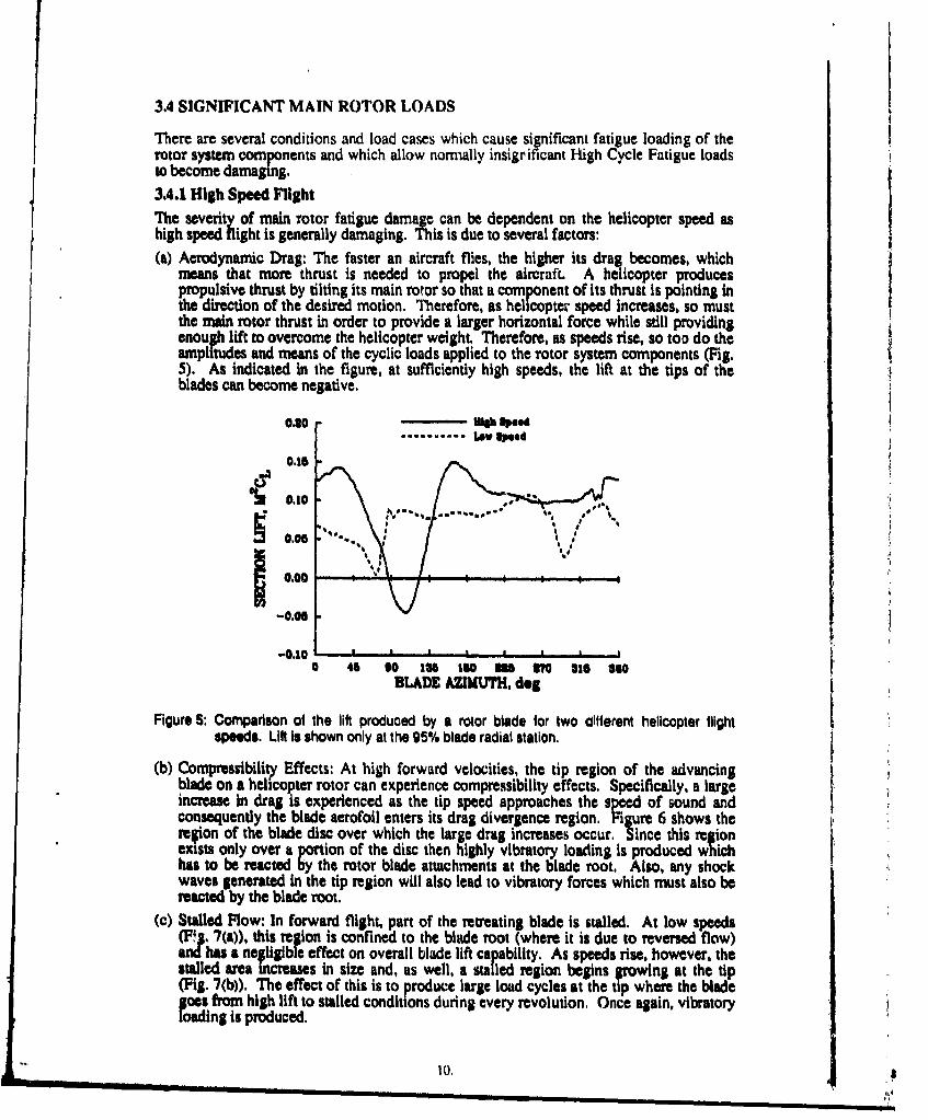
There are several conditions and load cases which cause significant fatigue loading of therotor system components and which allow normally insigrificant High Cycle Fatigue loadsto become damaging.3.4.1 High Speed FlightThe severity of main rotor fatigue damage can be dependent on the helicopter speed ashigh speed flight is generally damaging. This is due to several factors:(a) Aerodynamic Drag: The faster an aircraft flies, the higher its drag becomes, which
means that more thrust is needed to propel the aircraft. A helicopter producespropulsive thrust by tilting its main rotor so that a component of its thrust is pointing inthe direction of the desired motion. Therefore, as helicopter speed increases, so mustthe main rotor thrust in order to provide a larger horizontal force while still providing
enou• 0 lit ' vrome "he helicopter weight. Therefore, as speeds rise, so too do theampltudes and means of the cyclic loads applied to the rotor system components (Fig.5). As indicated in the figure, at sufficiently high speeds, the lift at the tips of theblades can become negative.
0.30 High Speed.......... low Speed
0.18
0.10,
0.00
-0.06
"04.10 ' n .. , ,a 45 O0 1I8 toe U o 316 So1 8o
BLADE AZIMUTH, deg
Figure 5: Comparison of the lift produced by a rotor blade for two different helicopter flightspeeds. Lift Is shown only at the 95% blade radial station.
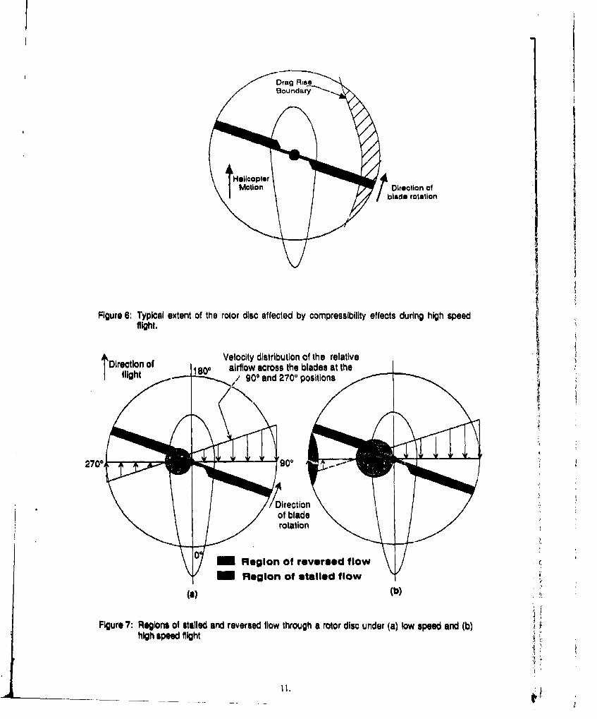
(b) Compressibiliýy Effects: At high forward velocities, the tip region of the advancingblade on a helicopter rotor can experience compressibility effects. Specifically, a largeincrease in drag is experienced as the tip speed approaches the speed of sound andconsequently the blade aerofoil enters its drag divergence region. Figure 6 shows there~ion of the blade disc over which the large drag increases occur, Since this regionexists only over a portion of the disc then highly vibratory loading Is produced whichhas to be reacted by the rotor blade attachments at the blade root. Also, any shockwaves generated in the tip region will also lead to vibratory forces which must also bereacted by the blade root.
(c) Stalled Flow: In forward flight, part of the retreating blade is stalled. At low speeds(Ffg. 7(a)), this region is confined to the blade root (where it is due to reversed flow)andhas a negligible effect on overall blade lift capability. As speeds rise, however, thestalled area increases in size and, as well, a stalled region begins *rowing at the tip(Fig. 7(b)). The effect of this is to produce large load cycles at the tip where the bladegoes from high lift to stalled conditions during every revolution, Once again, vibratoryloading is produced.
10, .i . . . . . . . . . . . .
Drag RiseBoundary~.
SHelloopteri Direction of
blade rotation
Figure 6: Typical extent of the rotor disc affected by compressibility effects during high speedflight.
Direction of Velocity distribution of the relative
flight 18, airflow across the blades at theS900 and 2700 positions
270090
D~irection
of bladerotation ,
0 Region of reversed flow
- Region of stalled flow(el (b)
Figure 7: Regions of stilled and reversed flow through a rotor disc under (a) low speed and (b)high speed flight
-.1"
Flight test results' 2 for a Lockheed Model 286 helicopter confirm this high speed effect onthe loads with the hub bending moments (both flap and lag) being much higher in highspeed flight than in hover.
Typically, high speed flight is associated with such conditions as battlefield operations,mercy flights, search and rescue operations (the dash to the search area) and possibly anti-submarine warfare depending on how. quickly the helicopter must move from one point toanother. The effects of high speed flight may also be exacerbated by high gross weights,bad weather and adverse centre-of-gravity positions which all require more rotor thrust tobe produced than would otherwise be needed.
The severity of the damage induced by high speed flight was such that it prompted theCivil Aviation Authority in the United Kingdom to institute the following:
"... the foirwardflight speed (is restricted] such that the never exceed speed Vys should notbe exceeded in the event of a slight upset i.e. (f the maximum level flight speed of thehelicopter VH is higher or equal to VNE then a normal maximum operating speed Vvoshould be imposed which is 10% or 10 kIs less than VyS ... This we believe has been amajor contribution to helicopter safety.,,
3.4.2 Transitional Flight
Transitional flight is defined as the condition existing when a helicopter Is in a fghtcondition between hover and horizontal flight. It is a relative rather than absolute flightcondition and depends on such things as helicopter speed, main rotor speed, and ambientwind strength. Liardui states that transitional flight often generates the highest vibratorystresses. Darts and Schutz' 5 confirm this with stress histories from a Westland Sea King inwhich they note that the "... normal approach to the hover (is] one of the manoeuvres that
produces the severest loadingof . Lo rd demonstrates the effect that transitional flight canhave on the fatigue life of a main rotor blade. Using a helicopter "transport mission"
ectrum to give a bae fr e he compares the lives obtained under other missions. One ofTsthesecro sprying, gives an p proximately the same lfe unless prolonged transitional flightis Includ in the spectrum, in which case the fatigue life becomes less than half the base
In terms of frequency of occurrence and severity, the transition from forward flight tohover is the worst type of transitional fin Wherea pilots will usualm e theihelicopters quickly from hover to forward figting, te rerse case is different. When a pilotwishes to hover, it is generally in preparation for landing or to hover over a specific spot.Thus the pilot must transition more slowly and therefore spend more time in the transitionregion with a consequent penalty in the fatigue damage incurred.
The cause of these transitional, vibrational loads is linked to the blade dynamics. A changein flight condition means a change in the required rotor thrust. However, because theblade is a flexible structure which is rotating, cycling in pitch, flapping up and down,leading, lagging, and twisting, any request from the pilot to change state must producetransient responses.3.4.3 Ground-Air-Ground CyclesGround-Air-Ground (GAG) cycles produce siiicant Low Cycle Fat i ue damage to rotorsystem comiponents' 3' 22'25. The GAG cycle is a single load Cycle which is applied to each
compoent oce pr flight. It is made up from the variation in load between the maximumand nium oaed's experienced by each component during a flight24 (Fig. 8). Themaximum load will occur sometime during flight, but the minimum load usual ly occurs onthe ground (hence the mnae, ground-air-ground) where it is either zero or slightlynegative'. However, the minimum GAG cycle load may occur during flight if thehelicopter enters autorotation mode (see Section 3.4.4).
"A negative Igound load occurs, for example, in a helicopter main rotor blade. This comes aboutbecause when a main rotor blade is stationary, it droops, thus placing its lower surface in compression.
12,
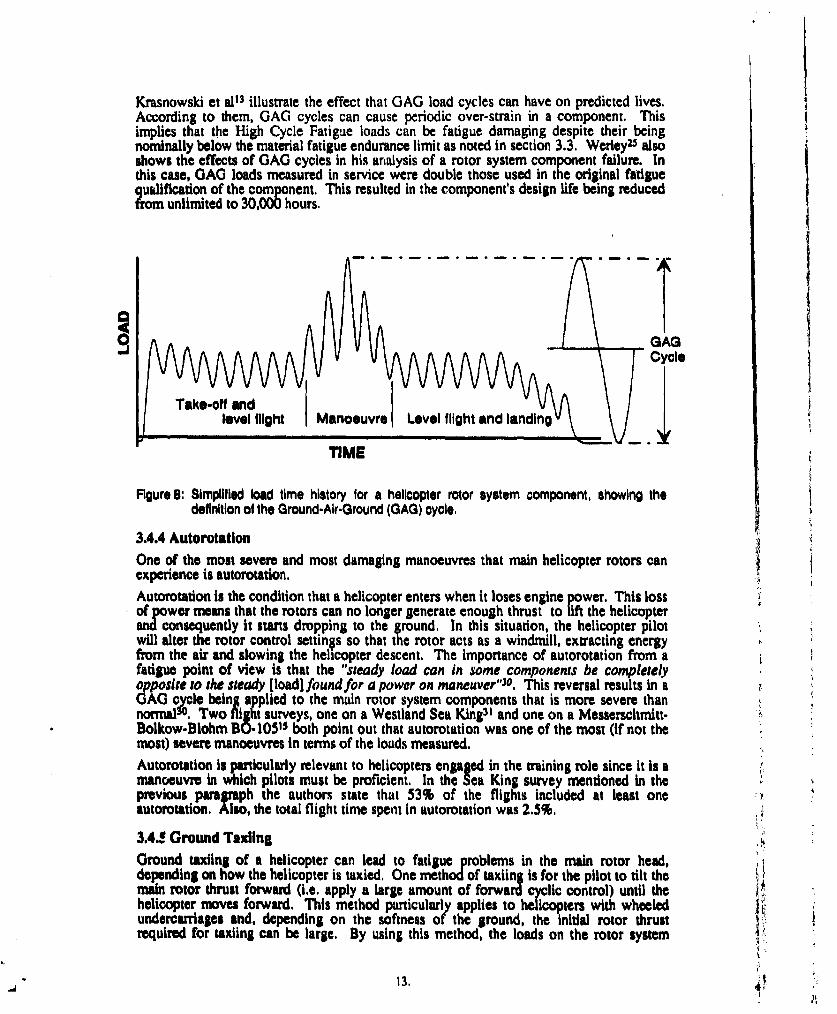
Krasnowski et al" illustrate the effect that GAG load cycles can have on predicted lives.According to them, GAG cycles can cause periodic over-strain in a component. Thisimplies that the High Cycle Fatigue loads can be fatigue damaging despite their beingnominally below the material fatigue endurance limit as noted in section 3.3. WerleyZ5 alsoshows the effects of GAG cycles in his analysis of a rotor system component failure. Inthis case, GAG loads measured in service were double those used in the original fatiguequalification of the component. This resulted in the component's design life being reducedfrom unlimited to 30,000 hours.
a
0 GAG
ITake-off and
level flight Manoeuvre Level flight and landing
TIME
Figure 8: Simplified load time history tor a helicopter rotor system component, showing thedefinition ol the Ground-Air-Ground (GAG) cycle.
3.4.4 Autorotatlon
One of the most severe and most damaging manoeuvres that main helicopter rotors canexperience is autorotation.
Autorotation is the condition that a helicopter enters when it loses engine power. This lossof power means that the rotors can no longer generate enough thrust to lift the helicopterand consequently it starts dropping to the ground. In this situation, the helicopter pilotwill alter the rotor control settings so that the rotor acts as a windmill, extracting energyfrom the air and slowing the helicopter descent. The importance of autorotation from a 3fatigue point of view is that the "steady load can in some components be completelyF0posire to the steady [load] found for a power on maneaver"30 . This reversal results in ai
AG cycle being a plied to the main rotor system components that is more severe thannormal3 0. Two flight surveys, one on a Westland Sea King3' and one on a Messerschmitt-Bolkow-Blohm BO-105 15 both point out that autorotation was one of the most (if not themost) severe manoeuvres in terms of the loads measured.
Autorotation is particularly relevant to helicopters engaged in the training role since it is a Ymanoeuvre in which pilots must be proficient. In the Sea King survey mentioned in theprevious pararaph the authors state that 53% of the flights included at least oneautorotation. Also, the total flight time spent in autorotation was 2.5%.
3.4. Ground Taxiing
Ground taxiing of a helicopter can lead to fatigue problems in the main rotor head,depending on how the helicopter is taxied. One method of taxiing is for the pilot to tilt themain rotor thrust forward (i.e. apply a large amount of forward cyclic control) until thehelicopter moves forward. This method particularly applies to helicopters with wheeledundercarriages and, depending on the softness of the ground, the initial rotor thrustrequired for taxiing can be large. By using this method, the loads on the rotor system
13,I'
components will consist of large amplitude cycles which can be very fatigue damaging. Asecond method of taxiing a helicopter is first to generate enough rotor thrust such that thehelicopter almost lifts off and then apply forward cyclic control to initiate the taxi. Thisleads to higher mean loads than the first method, but cyclic load amplitudes are muchreduced. This reduces the fatigue damage caused by the taxiing.Gralnger32 raises the notion that ground taxiing of a helicopter may induce high loads. Inparticular, for a helicopter with a semi-rigid head (and a rigid hlcad as well, plesumably),"... small control movements give high rates of respo'iae and correspondingly highloadsSymonds33 mentions that, early in its life, the AH-64 Apache suffered from a series offatigue cracks in its main rotor hub. The cause of these cracks puzzled the engineers atMcDonnell Douglas Helicopter Company (MDHC) unti they found out that the Apachepilots preferred to ground taxi their machines by applying full forward cyclic with almostzero collective. In other words, they were using the main rotor to pull the entire weight ofthe helicopter during the taxiing which produced lase cyclic bending moments in the rotorblade support structure and led to the fatigue cracking. To stop this damage occurring,MDHC engineers recommended that the amount of ground taxiing be mnimised, but,when ground taxiing was unavoidable, the procedure to be followed should be the same asthe second method described at the beginning of this Section.
3.4.6 Droop Stop PoundingDroop stops are structural elements on the main rotor hub which come into play when thehelicopter is at rest. In this condition, the flexible rotor blades sag under their own weight,but the amount of droop is limited by each blade's droop stop. Normally, the blades arewell clear of the stops during power-on conditions or the stops themselves are retractedout of the way, but under some flight conditions contact can occur27,34. Kieras34monitored these contacts on a U.S. Army Black Hawk and found that they occurred at arate of five seconds per flight hour. The conditions under which contact occurred were:main rotor engagement, backwards taxiing, slope landings and run-on landings when themain rotor was used to brake the aircraft. In general, contact may occur during anyground condition in which the cyclic stick is well off-centre when the collective is reduced.Werley•s shows that such loads can be large and can cause major reductions in thepredicted lives of components.The danger of droop stop pounding is such that Kieras gives this advice: "Pilots shouldavoid DSP [droop stop pounding] by using proper technique as pounding of the stops isquite damaging to blade retention components."14
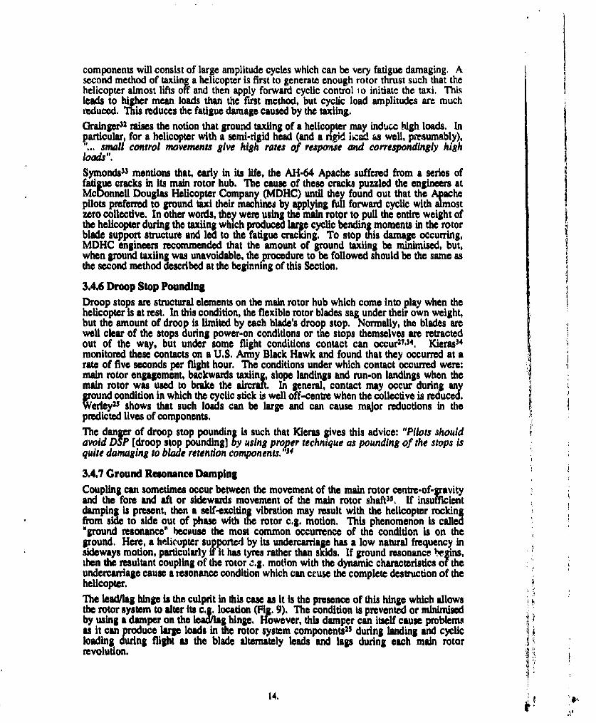
3.4.7 Ground Resonance DampingCoupling can sometimes occur between the movement of the main rotor centre-of-gravityand the fore and aft or sidewards movement of the main rotor shaft3s. If insufficientdamping is present, then a self-exciting vibration may result with the helicopter rockingfrom side to side out of phase with the rotor c.g. motion, This phenomenon is called"ground resonance" because the most common occurrence of the condition is on theground. Here, a helicopter supported by its undercarriage has a low natural frequency insideways motion, particularly if it has tyres rather than skids. If ground resonance hgins,then the resultant coupling of the rotor ,.g. motion with the dynamic characteristics of theundercarriage cause a resonance condition which can cruse the complete destruction of thehelicopter.The lead/lag hinge is the culprit in this case as it is the presence of this hinge which allowsthe rotor system to alter its c.g. location (Fig. 9). The condition is prevented or minimisedby using a damper on the lead/lag hinge. However, this damper can Itself cause problemsas it can produce large loads in the rotor system components25 during landing and cyclicloading during flight as the blade alternately leads and lags during each main rotorrevolution.
14.
,, C.G. of rotor syste
Actual rotor blade location I
Rotor blade location If no -.lead or lag were present
G. of rotor system
Front view of helicopter View (from above) of helicopter rotor
J,
Figure 9: Movemen of the rotor o.g. postion as the Individual rotor blades alternately lead and
ISO.
3.4.8 Operations From SlopesIf a helicopter takes off or lands sideways on a sloping surface then the weight of thevehicle will be temporarily supported by one side of e undercarriage only. According toCrichlow et 112, this produces a bending moment in the main rotor shaft which the rotormust resist. In their flight tests, on slopes of up to 100 Crichlow et al measured "... bladeflapping loads which were 80% as great as the maximum encountered in the most severepitch manoeuvre. However, these high loads lasted for a greater period of time, thus, thepeak load count was greater".
Note that it is not only take-offs and landings from hills that come under this heading. Thedecks of ships can also be considered as sloping surfaces since, in most sea conditions,ships roll and pitch.
3.4.9 Maritime OperationsMaritime operations include operations from ships and general over-water flying by land-based helicopters (e.g. oil-rig supply helicopters).
Over-water flying may induce fatigu loading if the helicopter is flying in air that is heavywith salt. Kay and Daniels indicate that helicopters operating in the North Sea canexperience vibrational rotor loads due to salt accumulation on the blades. On the worstdays, they found that salt accumulation could occur at altitudes up to 2000 feet.
Shipboard operations impose severe conditions on helicopters with the main problemsa= g in the undercah-iage (discussed later). As far as the main rotor Is concerned,shipboard operations may have an Influence on the rotor loads when the helicopter is flyingwithin the ship airwake. No specific studies have been made into the interaction betweenmain rotor loads and ship airwikes so no definite statements can be made about the effectsof this interaction. However, it seems likely that a main rotor, partially or fully inside theturbulent airwake from a ship would be affected. It is possible that the load variationsinduced could be fatigue damaging.
3.4.10 Pitch AeealeratlonCrichlow et aI1s state that the angular acceleration in pitch has an important effect on mainrotor loads and offer their flight test data as proof. In the data, they measured high cyclicflap loads under conditions of high pitch acceleration.
3.4.11 Negative ThrustAnother important load case for main rotor components, but not the rotor blades, appliesto helicopters which can generate negative thrust from their rotors. This can be in nap-of-the-earth flying which requue's negative-g push-overs (e.g. Black Hawk and Apache) ornegative thrust during hover (Westland Lynx or Sikorsky S-69 Advancing Blade Conc,-ptdemonstrator). The reason for the negative hover thrust capability, especially in a navalhelicopter such as the Lynx is that, having landed on a ship's deck, the helicopter pilot canuse negative thrust to force the helicopter hard against the deck until the ground crewsecure the helicopter. By its nature though, the negative hover thrust condition will causea large ground-air-ground cycle to be applied to some of the rotor system components,and so some navies may elect not to use the capability at all (e.g. the Royal NetherlandsNavy").
3.4.12 Blade SailingBlade afa i aaterm used to describe the behaviour that rotor blades can exhibit dudngrotor shut down after landing. Rotor blades can be thought of as flexible beams whichobtain their rquired stiffnes during flight through the action of centrifugal force.However, after landing, as the rotors slow down, the pilot loses effective control over tieblades since their stiffness decreases dramatically with the decrease in rotational speed and V
16..S! 4r
corresponding centrifugal force. In this situation, a sudden gust of wind can cause theblade to make large up and down flapping motions. This can cause the blades to hit theground and shatter, chop through tailbooms or strike anyone unlucky enough to be insidethe rotor radius. From a fatigue point of view, blade sailing can contribute to the GAGCycle by increasing the peak negative loads experienced by a rotor blade. Blade sailing ismore likely to occur if the rotor blade construction is very flexible and/or the rotor headuses hinges to allow flapping motion.
3.U TAIL ROTOR LOADS
The tail rotor may be viewed as a scaled down version of the main rotor and, in manyrespects, the generation of loads is the same. The main differences are that the tail rotorrotates at a much higher speed than the main rotor: 15 - 30 Hz versus 3 - 6 Hzrespectively, and that the magnitudes of the loads (but not the stresses) are much smaller.Hence, the tail rotor experiences more high cycle fatiguo load cycles than the main rotor.
The most critical fatigue regimes for a tall rotor are the hover, low speed flight, rearwardsflight and sideways flight2,3 2. This is because under these conditions the tail rotor isproviding all or most of the force required to counteract the torque of the main rotor.
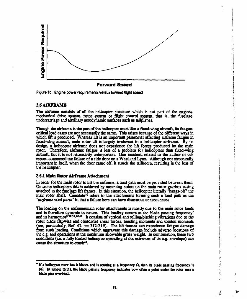
Also, rearwards flight can generate high tail loads, especially if the helicopter is unstable inthis flight mode. As forward speed increases, the engine power required to fly thehelicopter decreases rapidly before reaching a minimum, generally near its maximumendurance .Speed, and then begins to increase again (Fig. 10). Therefore, the taul rotorthrust requized to counteract the main rotor torque decreases with decrease in enginepower. In addition, fins mounted on the helicopter tailboom begin to generate significataerodynamic forces which are used to aid the tail rotor in its anti-torque work.Consequently, the tail rotor thrust required is again reduced. In helicopter teminology,the tail rotor is said to be unloading. = speeds rise further and the engine power requiredincreases, the tail rotor thrust must also increase, but due to the presence of the fins theanti-torque thrust required from the tail rotor is not as large as at low speeds.
GrainSer32 cites amplitude and rate of yaw as being the most critical parameters thoughoffers no evidence to support this. High rates of yaw and/or large yaw angles areaccompanied by large changes in tail rotor loads and the larger the change in load, thegreater the fatigue damage caused. McCue et aP3 in their examination of air-to-air combatroles for helicopter also make the observation that high yaw rates and sideflaremanoeuvres can generate large loads on the tail rotor.
Manoeuvres which correspond to these conditions include rapid turns, turns with abruptstops, steady sideslip, tail rotor pedal reversals, and sideways flight. Rearwards flightmight also be included if the helicopter is unstable when flying backwards. Maltby andHicks"' note that the Westland Sea King does have this instability and therefore inrearwards flight, '... high rates of turn in the yaw axis can easily be generated. Large tailrotor loads might be anticipated in these circumstances". The conditions whichcorrespond to these manoeuvres include landing, search and rescue (low speedmanoeuvrlng to effect a rescue), anti-submarine warfare (during loitering while listening tosonobuoy signals), battlefield operations, and crop dusting.
17.
I.'I
'IC
Forward Speed
Figure 10: Engine power requirements versus forward flight speed
3.6 AIRFRAMEThe airframe consists of all the helicopter structure which is not part of the engines,mechanical drive system, rotor system or flight control system, that is, the fuselage,undercarriage and auxiliary aerodynamic surfaces such as tailplanes.
Though the airframe is the part of the helicopter most like a fixed-wing aircraft, its fatigue-critical load cases are not necessarily the same. This arises because of the different ways inwhich lift is produced. Whereas lift is an important parameter affecting airframe fad infixed-wing aircraf main rotor lift is largely irrelevant to a helicopter airframe. vyitsdesign, a helicopter airframe does not experience the lift forces produced by the mainrotor. T•erefore, airframe fatigue is less of a problem for helicopters than fixed-wingaircraf but it is not necessarily unimportant. One incident, related to the author of thisreport, concerned the failure of a side door on a Westland Lynx. Although not structurallyimportant in itself, when the door came off, it struck the tailboom, resulting in the loss ofthe helicopter.
3.6.1 Main Rotor Airframe AttachmentIn order for the main rotor to lift the airframe, a load path must be provided between them.On some helicopters this is achieved by mounting points on the main rotor gearbox casingattached to the fuselage lift frames. In this situation, the helicopter literally 'hangs-off' themain rotor shaft. Canedale1 o refers to the attachments forming such a load path as the"aiyrrame vital parts" in that a failure here can have disastrous consequences.The loading on the airframe/main rotor attachments is mostly due to the main rotor loadsand is therefore dynamic in nature. This loading occurs at the blade passing frequency'and its harmonics.93539.40,4 1. It consists of vertical and rolling/pitching vibrations due to therotor blade flapwise and chordwise shear forces, bending moments and torsion moments(see, particularly, Ref. 42, pp 312-319). The lift frames can experience fadtue damagefrom such loading. Conditions which aggravate this damag, include adverse locations ofthe c.g. and operations at the maximum allowable gross weight. In combination, these twoconditions (i.e. a fully loaded helicopter operating at the extremes of its c.g. envelope) cancause the structure to crack42.
"If a heficopter rot hu b blades and is rotating at a frequency fl, then its blade passing frequency isbO. In simple terms, the blade passing frequency indicates bow often a point under the rotor sees ablade pau overhead.
18.
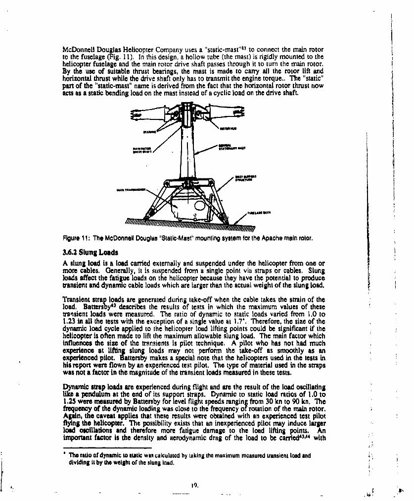
McDonnell Douglas Helicopter Company uses a "static-mast"83 to connect the main rotorto the fuselage (Fig. 11), In this design, a hollow tube (the mast) is rigidly mounted to thehelicopter fuselage and the main rotor drive shaft passes through it to turn the main rotor,By the use of suitable thrust bearings, the mast is made to carry all the rotor lift andhorizontal thrust while the drive shaft only has to transmit the engine torque.. The "static"part of the "static-mast" name is derived from the fact that the horizontal rotor thrust nowacts as a static bending load on the mast instead of a cyclic load on the drive shaft,
/IMo"" MU
Figure 11: The McDonnell Douglas "Static.Mast" mounting system for the Apache main rotor.
3.6.2 Slung Loads
A slung load is a load carried externally and suspended under the helicopter from one ormore cables. Generally, it is suspended from a single point via straps or cables. Slungloads affect the fatigue loads on the helicopter because they have the potential to producetransient and dynamic cable loads which are larger than the actual weight of the slung load.
Transient strap loads are generated during take-off when the cable takes the strain of theload. Battersby4 3 describes the results of tests in which the maximum values of thesetranisient loads were measured. The ratio of dynamic to static loads varied from 1.0 to1.23 in all the tests with the exception of a single value at 1.7". Therefore, the size of thedynamic load cycle applied to the helicopter load lifting points could be significant if thehelicopter is often made to lift the maximum allowable slung load. The main factor whichinfluences the size of the trarsients is pilot technique. A pilot who has not had muchexperience at lifting slung loads may not perform the take-off as smoothly as anexperienced pilot. Battersby makes a special note that the helicopters used in the tests inhis report were flown by an experienced test pilot. The type of material used in the strapswas not a factor in the magnitude of the transient loads measured in these tests.
Dynamic strap loads are experienced during flight and are the result of the load oscillatinglike a pendulum at the end of its support straps. Dynamic to static load ratios of 1.0 to1.23 were measured by Battersby for level flight speeds ranging from 30 kn to 90 kn, Thefrequency of the dynamic loading was close to the frequency of rotation of the main rotor.Again, the caveat applies that these results were obtained with an experienced test pilotflying the helicopter. The possibility exists that an inexperienced pilot may induce largerload oscillations and therefore more fatigue damage to the load lifting points. Animportant factor is the density and aerodynamic drag of the load to be carried43,"4 with
The ratio of dynamic to static was calculated by taking the maximum measured transient load anddividing It by th, weight of the slung load,
4,19,
Battersby finding that high density, low drag bodies tended to oscillate while low density,high drag loads maintained an almost constant trailing angle under the helicopter. Anotherimportant factor is the size of the load and its distance from the main rotor. Large loadscarried close under the helicopter developed significant dynamic loading due to the mainrotor downwash.
There is also the 'ossibili that the load may become aerodynamically unstable if thehelicopter is travelling too ast. This would induce high loads, not only in the airframe butalso hi the main and tail rotors as the pilot fought to regain control. In this case though, itis expected that a pilot would jettison such a load before the helicopter becameuncontrollable and suffered damage.
A special case of the slung load that merits mention is the "towed load". In this case, thehelicopter is towing a load that is either on or under water. Towing through water willgenerate higher static tension loads in the tow cable than If the load were simply beingcarried through the air..The effect on the dynamic loads is not as clear however, becausewhile the osc.llatory motion of the load will be dampened by the water, wave motion mayexacerbate it, The towed load case can be critical for the main rotor drive shaft as theextra horizontal thrust means increased bending stresses on the shaft, unless the helicopterhas a "static-mast" or similar (see Section 3.6.1).
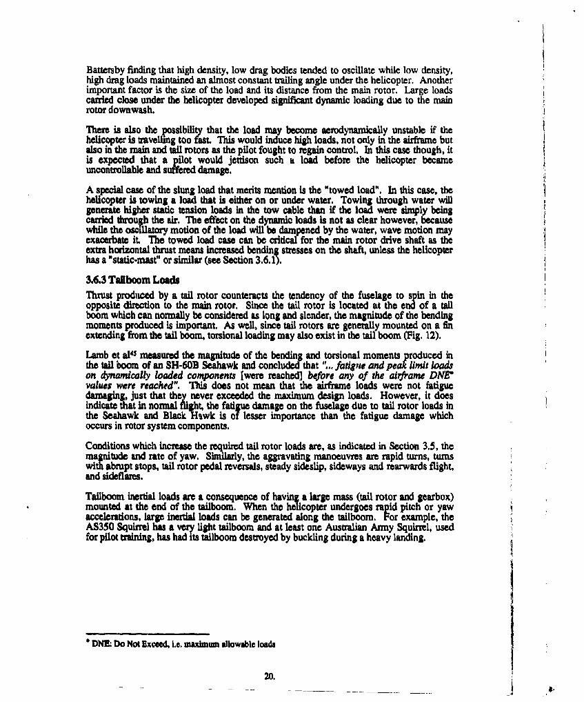
3.6.3 Tailboom Loads
Thrust produced by a tail rotor counteracts the tendency of the fuselage to spin in theopposite direction to the main rotor. Since the tail rotor is located at the end of a tailboom which can normally be considered as long and slender, the magnitude of the bendingmoments produced is important. As well, since tail rotors are generally mounted on a finextending from the tail boom, torsional loading may also exist in the tail boom (Fig. 12).
Lamb et al4s measured the magnitude of the bending and torsional moments produced inthe tail boom of an SH-60B Seahawk and concluded that "... fatigue and peak lmit loadson dynamically loaded components [were reached] before any of the airframne DNE"values were reached". This does not mean that the airframe loads were not fatiguedamaging, just that they never exceeded the maximum design loads. However, it doesindicate that in normal flight, the fatigue damage on the fuselage due to tail rotor loads inthe Seahawk and Black lHwk is of lesser importance than the fatigue damage whichoccurs in rotor system components.
Conditions which increase the required tail rotor loads are, as indicated in Section 3.5, themagnitude and rate of yaw. Similarly, the aggravating manoeuvres are rapid turns, turnswith abrupt stops, tail rotor pedal reversals, steady sideslip, sideways and rearwards flight,and sideflares.
Tailboom inertial loads are a consequence of having a large mass (tail rotor and gearbox)mounted at the end of the tailboom. When the helicopter undergoes rapid pitch or yawaccelerations, large inertial loads can be generated along the tailboom. For example, theAS350 Squirrel has a very light tailboom and at least one Australian Army Squirrel, usedfor pilot training, has had its tailboom destroyed by buckling during a heavy landing.
* DNEk Do Not Exceed, i.e. maximum allowable loads
20.
b !i
p'!ii
N
21. . f r
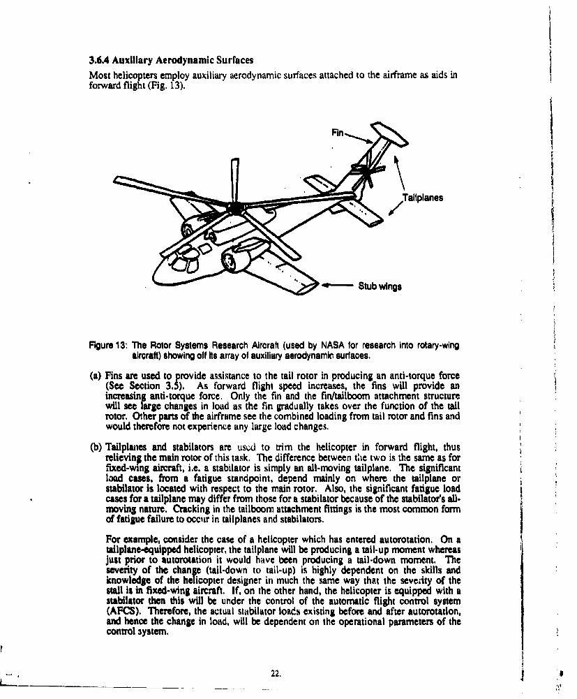
3.6.4 Auxiliary Aerodynamic SurfacesMost helicopters employ auxiliary aerodynamic surfaces attached to the airframe as aids inforward flight (Fig. 13).
Tallplanes
•*"- •Stub wings
Figure 13: The Rotor Systems Research Aircraft (used by NASA for research into rotary-wingaircralt) showing off hs array of auxiliary aerodynamic surfaces,
(a) Fins are used to provide assistance to the tail rotor in producing an anti-torque force(See Section 3.5). As forward flight speed increases, the fins will provide anincreasing anti-torque force. Only the fin and the fin/tailboom attachment structurewill see large changes in load as the fin gradually takes over the function of the tailrotor. Other pans of the airframe see the combined loading from tail rotor and fins andwould therefore not experience any large load changes.
(b) Tailplanes and stabilators are used to trim the helicopter in forward flight, thusrelieving the main rotor of this task. The difference between the two is the same as forfixed-wing aircraft, i.e. a stabilator is simply an all-moving tailplane. The significantload cases, from a fatigue standpoint, depend mainly on where the tailplane orstabilator is located with respect to the main rotor. Also, the significant fatigue loadcases for a tailplane may differ from those for a stabilator because of the stabilator's all-moving nature. Cracking in the tailboom attachment fittings is the most common formof fatigue failure to occur in tailplanes and stabilators.
For example, consider the case of a helicopter which has entered autorotation. On atallplane-equipped helicopter, the tailplane will be producing a tail-up moment whereasjust prior to autorotation it would have been producing a tail-down moment. Theseverity of the change (tail-down to tail-up) is highly dependent on the skills andknowledge of the helicopter designer in much the same way that the severity of thestall is in fixed-wing aircraft. If, on the other hand, the helicopter is equipped with astabilator then this will be under the control of the automatic flight control system(AFCS). Therefore, the actual stabilator loads existing before and after autorotation,and hence the change in load, will be dependent on the operational parameters of thecontrol 3ystem.
22,
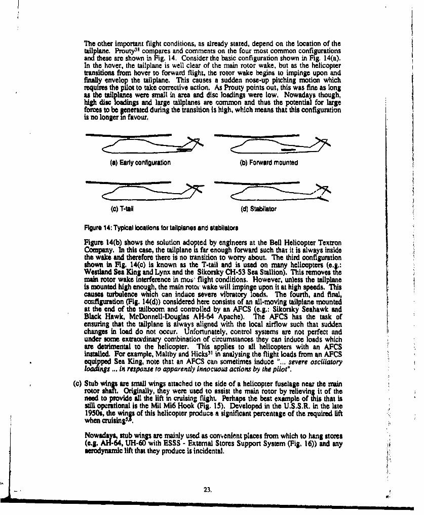
The other important flight conditions, as already stated, depend on the location of thetailplane. Prouty38 compares and comments on the four most common configurationsandthese are shown in Fig. 14. Consider the basic configuration shown in Fig. 14(a).In the hover, the tailplane is well clear of the main rotor wake, but as the helicoptertransitons from hover to forward flight, the rotor wake begins to impinge upon andfinally envelop the tallplane. This causes a sudden nose-up pitching motion whichrequires the pilot to take corrective action. As Prouty points out, this was fine as longas the tailplanes were small in area and disc loadings were low. Nowadays though,higdisc loadings and large tailplanus are common and thus the ential for largerces to be generated during the transition is high, which means that this configurationis no longer in favour.
(a) Early configuration (b) Forward mounted
(o) T-tail (d) Stabliator
Figure 14: Typical locations for tallplanes and stabilators
Figure 14(b) shows the solution adopted by engineers at the Bell Helicopter TextronCompany. In this case, the taliplane is far enough forward such that it is always insidethe wake and therefore there is no transition to worry about. The third configurationshown in Fig. 14(c) is known as the T-tail and is used on many helicopters (e.g.:Westland Sea King and Lynx and the Sikorsky CH-53 Sea Stallion). This removes themain rotor wake interference in mous flight conditions. However, unless the tallplaneis mounted high enough, the main rotoi wake will impinge upon it at high speeds. Thiscauses turbulence which can induce severe vibratory loads. The fourth, and final,configuration (Fig. 14(d)) considered here consists of an all-moving tailplane mountedat the end of the tailboom and controlled by an AFCS (e.g.: Sikorsky Seahawk andBlack Hawk, McDonnell-Douglas AH-64 Apache). The AFCS has the task ofensuring that the tailpiane is always aligned with the local airflow such that suddenchangs in load do not occur. Unfortunately, control systems are not perfect andunder some extraordinary combination of circumstances they can induce loads whichare detrimental to the helicopter. This applies to all helicopters with an AFCSinstalled. For example, Maitby and Hicks3' In analysing the flight loads from an AFCSequipped Sea King, note that an AFCS can sometimes induce "... severe oscillatoryIoad ngs ... in response to apparently innocuous actions by the pilot".
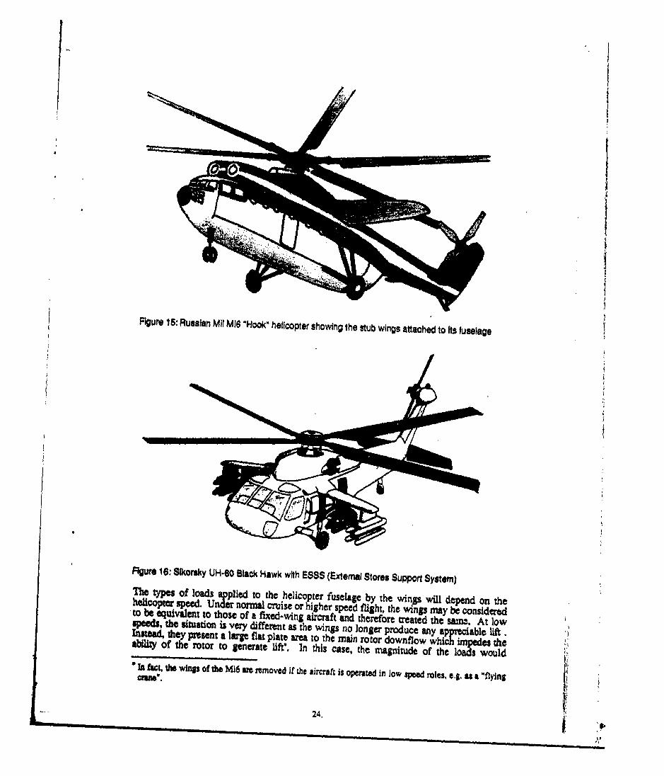
(c) Stub wings are small wings attached to the side of a helicopter fuselage near the mainrotor shaft. Originally, they were used to assist the main rotor by relieving it of theneed to provide all the lift in cruising flight. Perhaps the best example of this that isstill operational is the Mil Mi6 Hook (Fig. 15). Developed in the U.S.S.R. in the late1950s, the wings of this helicopter produce a significant percentage of the required lift,when cruisingS'.'
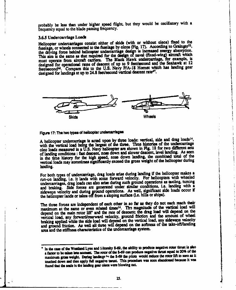
Nowadays, stub wings are mainly used as convenient places from which to hang stores(e.g. Z-64. UH-60 with ESSS - External Stores Support System (Fig. 16)) and anyaerodynamic lift that they produce is incidental.
23.
/I
Figure 15: Russian Mil MI6 "Hook' helicopter showing the stub wings attached to its fuselage
Figure 16: Sikorsky UH-60 Black Hawk with ESSS (External Stores Support System)The types of loads applied to the helicopter fuselage by the wings will depend on thehelicoptar speed. Under normal cruise or higher speed flight, the wings may be consideredto be equivalent to those of a fixed-wing aircraft aid therefore treated the satri.-. At loweeds, the situation is very different as the wings no longer produce any apprec"able lift.Instead, they present a large flat plate area to the main rotor downflow which lipedes theability of the rotor to generate lift*. In this case, the magnitude of the loads would"In fact, the wings of the Mi6 arm removed if the aircraft is operated in low speed roles, e~g. as a "flying
24.
probably be less than under higher speed flight, but they would be oscillatory with A
frequency equal to the blade passing frequency.
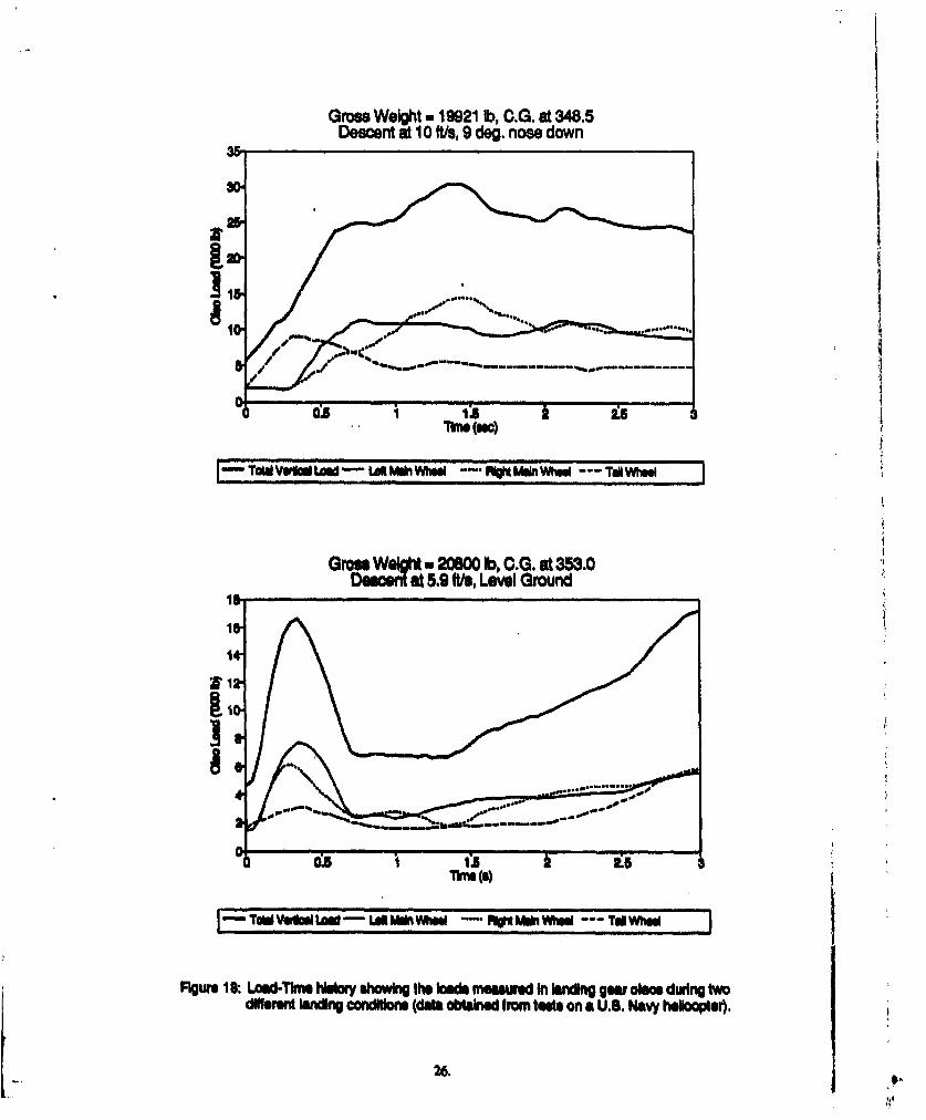
3.6.5 Undercarriage LoadsHelicopter undercarriages consist either of skids (with or without oleos) fixed to thefuselae, or wheels conneced to the floselage by oleos (Fig. 17). Accordiing to lraingr32,
tediig force behind helicopter unecr~g e inIs Incresed energ absorption.
This aim is the same as that ,,quiad for the desig~n olnaval (fixed-wing) aircraft whichmust operate from aircraft carriers. The Black Hawk undercarriage, for eample, Isdesigned for operational rates of descnt of up to 9 feet/second and the Seahawk at 12feet/second"d. Compare this to the U.S. Navy FIA-18 Hornet which has landing gear
designed for landings at up to 24.8 feet/second vertical descent rate'O.
Skids Wheels
Figure 17: The two types ol huiloopter undeerranage
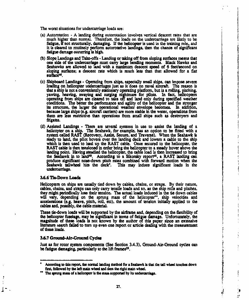
A helicopter undercarrsag is acted upon by thre loads: vertical, side and drag loads14,with"th vertical loa bIn the largest of the thre. Time histories of the undercarriageoleo loads measured InaU.S. Navy helicopter arn shown in Fig. 18 for two different setsof landing conditions:- fast descent. nose down and slower descent. level landing. As seenin the time history for the high speed, nose down landing, the combined total of thevertical loads may sometimes signiffcantly exceed the gross weight of the helicopter duringlanding.
For both tps of undercarriage, drag loads aris durnn landing if the helicopter makes arun-on ladn, i.e. it lands with some forwardl velocit. For helicopters with wheeledundercarriages, drag loads can also arise during such ground operations as taxiing, turningand braking. Side forces are generated under similar conditions, i.ýe. landing with asideways velocity and during ground operations. As well, significant side loads occur ifthe helicopter lands or taks 01foff masloping surface (i.e. hills or ships).
The three forces are independent of each other in so far as they do not each reach theirmaximumn at the same or even related times". TM magnitude of the vertical load will
deedon the min rotor llftand the rate of descent; the drag load will depend on thevertical load, any forwazrI/rearwan velocity, pound friction and the amount of wheelbraking applied while the side load wil =depd on the vertical load, any sideways velocityand pround friction. As well. all three wildepend on the softness of the take-oft/landIngarea and the stiffness characteristics of the undercarriage system.
*in fth cas of the Westian Lynx and sikorsky S49. the ability to produce megtive rotur thrust is alsoa factor to be taims into account. Tie rotor of doe W4 can produce negative threustl to 20% of the
maxitnum VrM weiht. Daftng tudingoIn' th 8469 the pilots would reduce the rotor lift to zero as ittouched down and fthe apply full negative Wrest This procedure was soon abandoned because it wasfound that the scals in die loanding gpar olmc were blowing OUt.
25.
Gross Weight.m 19921 lb, C.G. at 348.5Descent at 10 ft/s, 9 de.nose down
0:5 15
I TaliVwMaULoa- LsM*u Wh-i--- "nu t " MmWh-iTat he
Grass Weigt * 20800 lb, C.G. at 353.0Descen at 5.9 ft/a, Level Ground
iss
T dVO ULod - LaS miiWheel RuM LiWheel TadWhe
Figure 18: Lamd-Tkme hsoey showing the bfda measured In Winng gear olmo during twodiffere lnding condftone (data obthWe frm tests on a U.S. Navy heli soptr.
[ .26. #
The worst situations for undercarriage. loads are:(a) Autorotation - A landing during autorotation involves vertical descent rates that are
much higher than normal. Therefore, the loads on the undercarriage are likely to befatigue, if not structurally, damaging. If the helicopter is used in the training role, andit is cleared to routinely perform autorotative landings, then the chance of significantfatigue damage occurring is high.
(b) Slope Landings and Take-offs - Landing or taking off from sloping surfaces means thatone side of the undercarriage must carry larg bending moments. Black Hawks andSeahawks are allowed to land with a maximum descent speed of 6 feet/second onsloping surfaces; a descent rate which is much less than that allowed for a flatsurft ic .
(c) Shipboard Landings - Operating from ships, especially small ships, can impose severeloading on helicopter undercatriages just as it does on naval aircraft. The reason isthat a ship is not a conveniently stationary operating platform, but is a rollin, itching,yawm#, heaving, swaying and surin nfightmare for pilots. In fact, heicoptersoperating from ships are cleared to take off and land ony during specified weatherconditions. The better the perforinance and agility of the helicopter and the strongerits structure, the larger the operational weather envelope becomes. In addition,because large ships (e.g. aircraft carriers) are more stable in the water, operations fromthem are less restrictive than operations from small ships such as destroyers andfrigates.
(d) Assisted Landings - There are several systems in use to assist the landing of ahelicopter on a ship. The Seahawk, for example, has an option to be fitted with asystem called RAST (Recovery, Assist, Secure, and Traverse). When the Seahawk isready to land, the pilot hovers over the landing deck and lowers a cable to the shipwhich is then used to haul up the PlAST cable, Once secured to the helicopter, theRAST cable is then tensioned in order bring the helicopter to a steady hover above thelanding point. Having steadied the helicopter, the cabfe load is then Increased to bringthe Seahwk in to lind4g. According to a Sikorsky report4s, a RAST landing canproduce significant nose-down pitch rates combined with forward motion when theSea=awk Wallwheel hits the deck". This may induce significant loads in theundercarriage.
3.6.6 Tie-Down LoadsHelicopters on ships are usually tied down by cables, chains, or straps. By their nature,cables, chains, and straps can only carry tensile loads and so, as the ship rolls and pitches,they might periodically lose their tension. The actual loads induced in the tie down cableswill vary, depending on the sprung mass of the helicopter*', shi velocities and
rations (e. heave, itch, roll, etc), the amount of tension 6in ly applied to thecables and, sibthe cable material.These tie-down loads will be supported by the airframe and, depending on the flexibility ofthe helicopter fuselage, may be sgnificant in terms of fatigue damage. Unfortunately, themagnitude of these loads is not known by the author of this paper since an extensiveuteraure search failed to turn up even one report or article dealing with the measurement
of these loads.
3•.7 Ground-AiraGround CydesJust as for rotor system components (See Section 3.4.3), Ground-Air-Ground cycles canbe fatigue damaging, particularly to the lift frames39.
* AccoWing to this report, the normal landing method for a Seabawk is that the tail wheel touches downfirst, followed by the left main wheel and then the right main wheel.
* The sprung mass of a helicopter is the mass supported by its undercarriage.
27,
3.6.8 Panel ResonanceThe panels in a helicopter fuselage can be susceptible to structural resonances due to thehigh frequency loading transmitted by both the main and tail rotors32. Structural resonanceimplies the application of a large number of low magnitude load cyclei to the panels andtheir fasteners. Tail booms can be particularly susceptible to resonwnce problems sincethey are generally long and slender structures.
3.6.9 Main Rotor Wake/Fuselage InteractionsThis area has only recently begun receiving more than a cursory glace fromresearchersn9',20 21 and it remains to be seen whether loads generated during suchinteractions are significant or not. The report by Battersby 43 cited in section 3.6.2indicated that such interactions were important for slung loads carried on a cable, closeunder a helicopter fuselage.
Researchers at the University of Maryland2° in the U.S.A. performed an expeiment .inwhich they measured the unsteady pressures induced on the fuselage of a generichelicopter model with a four-bladed main rotor. They noted that the correspondingunsteady loads on the fuselage (lift, side force and pitching moment) are sinificant relativeto the mean wake interaction loads seen by the fuselage. T7he scope of this study though,did not extend as far as attempting to compare these loads with the loads seen by a normalhelicopter in flight.
It is interesting to note that researchers in a related field, wind turbine research, considerthat the interference between the turbine blades and their support tower to be an "...important fluctuating load source"30. Also, one NASA reportsl describes a wind turbinewhich was constructed with an open truss-style tower in an effort to minimise turbulentairflow on the rotor and turbulent loads on the tower.
28.
1.1
4. FATIGUE DESIGN
4.1 TRADITIONAL FATIGUE DESIGN METHODOLOGY
Helicopter manufacturers use what is known as the "safe-life" approach when determiningthe fatigue lives of components. This approach has three key elements: 52.5 3•54,
(I) Material and component fatigue data (i.e. S-N curves)(ii) Load spectrum(ifi) Damage hypothesis and cycle counting (relating the load spectrum and the S-N
curve)
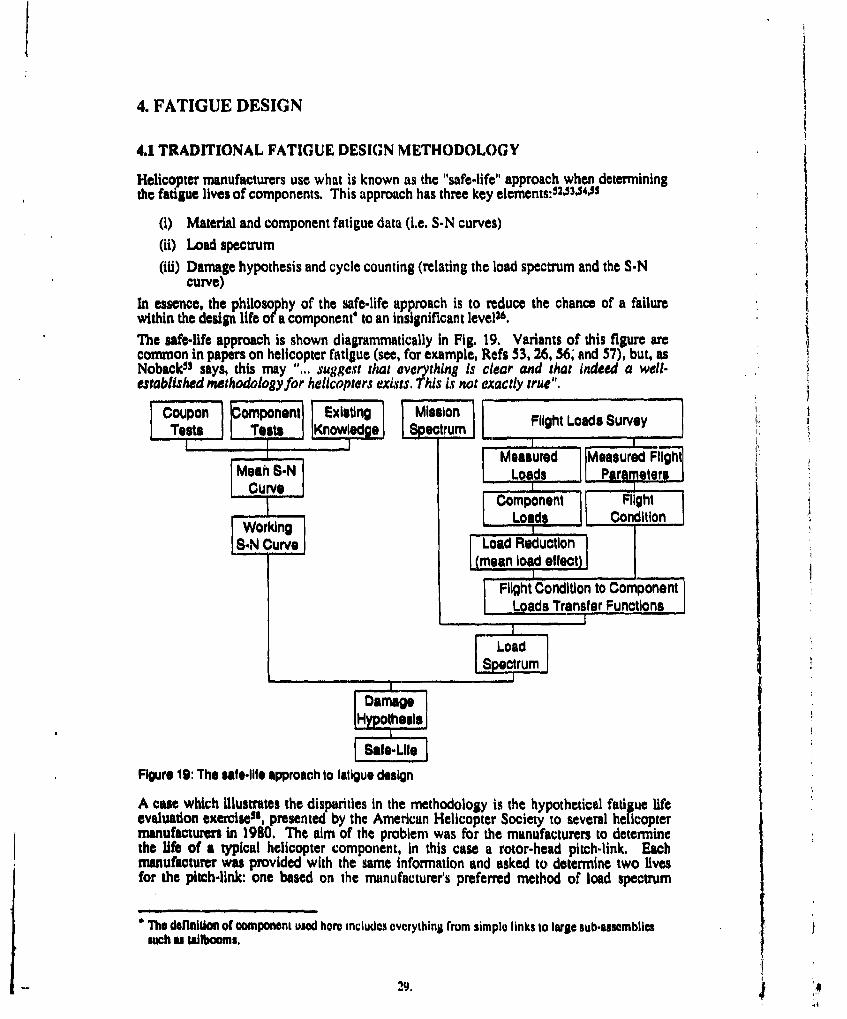
In essence, the philosophy of the safe-life approach is to reduce the chance of a failurewithin the design life of a component* to an insignificant levels.The safe-life approach is shown diagrammatically in Fig. 19. Variants of this figure arecommon in papers on helicopter fatigue (see, for example, Refs 53, 26, 56; and 57), but, asNoback 53 says, this may "... suggest that everything Is clear and that indeed a well-established methodology for helicopters exists. This is not exactly true".
Coupon omponent Eisn g Mission I Flight Loads SurveyTests T K..Sectrum
IMeasured IMeasured FlilghtMea SNLoads Parameters
Componernt FlightUi Loads ConditionWorkingI%
S-N Curve Load Reduction(mean load effect)'II
Flight Condition to ComponentLoads Transfer Functions
6Load
SpectrumII
IIl Damage
IHypothesis
Figure 19: The safe-life approach to fatigue design
A cue which illustrates the disparities in the methodology is the hypothetical fatigue lifeevaluation exercises', presented by the American Helicopter Society to several helicoptermanufacturers in 1980, The aim of the problem was for the manufacturers to determinethe life of a typical helicopter component, in this case a rotor-head pitch-link. Eachmanufacturer was provided with the same information and asked to determine two livesfor the pitch-link: one based on the manufacturer's preferred method of load spectrum
"The deflniton of component used hero includes overything fromm simple links to large sub-assembliesmuch s tailbooms.
29.
cycle counting ancl the other using the block iounting method*. The results5 9 arepresented in Table 3.
Table 3
Summary of calculated fatiSue lives (in hours) for the hypothetical pitch-link exercise
Manufacturer Block Counting Manufacturers preferredMethod cycle counting method
Aerospatiale" 9 58Agusta 804 6450Bellb 1831 27816Boeing-Vertol 1294 22523HugheSW 2594 24570Kaman 861 5901Sikorsky 240 470Notes: a Now part of Eurocopter
b Now Beli Helicopter Textronc Now McDonnell Douglas Helicopter Company
All the anal) ses followed the procedure of Fig. 19. As can be seen, the lives varied from 9to 2594 hours for t1he block nounting method and 58 to 27816 for the cycle countingmethod.To go into all the aspects of the safe-life method in minute detail is beyond the scope ofthis report, so what follows is an overview of the fatigue design techniques used by themajor helicopter manufacturers. For more detailed Information, the reader is referred tothe design guide' 0 issued by the Advisory Group for Aerospace Research andDevelopment. This 278-page document, published in 1983, contains an extensive surveyand evaluation of traditional helicopter fatigue design procedures.
4.1.1 The Working S-N CurveTo calculate fatigue lives, some relationship must be obtained between cyclic loads and thecorresponding fatigue damage produced for a particular component. In other words, an S-N curve (or curves) needs to be constructed for each component. This S-N curve isbased both on coupon and component tests, as well as the accumulated knowledge of eachmanufacturer. During the initial design phase of a new helicopter, components are notavailable so the designer makes do without component tests. In the design validationphase, components are available and are tested to validate the S-N data used. Examples ofsuch tests, performed on several components of the Apache, are given by Deveaux et al"l.Comonent tests are done on small numbers of components (usually not more thansJXS3. 2.63) because of time and cost constraints. In the Deveaux Apache tests, for example,the number of components tested varied from one to three. Components are tested underspoctrum loading, block loadin or S-N loading (i.e. constant amplitude loading). S-Ntesting tends to predominate2 4.3 ,*" mainly because of the "... difflculty (in] predicting thedynamic loads prior to flight testing ...".
What happens next is, nowadays, accomplished by computer, but the manual graphicalmethod of solution is presented aslit best describes the methods used.
" The block counting method is also known as the peak cycle counting method. This method, rather
than counting each cycle in a manoeuvre, assumes that the largest load cycle in the manoeuvre acts forthe entire duration of that manoeuvre (See Section 4.1.4)An S-N curve is one which defines the relationship between the endurance, N, of a material as afunction of the applied stress or load amplitude, S. N is given in terms of the number of load cyclesendured prior to fallure at a given value of S.
30.
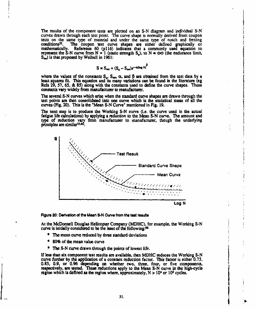
The results of the component tests are plotted on an S-N diagram and individual S-Ncurves drawn through each test point. The curve shape is normally derived from coupontests on the same type of material and under the same type of notch and frettingcondjtions53. The coupon test curve shapes are either defined graphically ormathematically. Reference 60 (pl16) indicates that a commonly used equation torepresent the S-N curve from N = 1 (static strength S.), to N = 0o (the endurance limit,S.) is that proposed by Weibull In 1961:
S = S. + (S. - S11)9,"e N
where the values of the constants S., S.., c0, and 0 are obtained from the test data by aleast squares fit. This equation and its many variations can be found in the literature (egRefs 29, 57, 65, & 85) along with the constants used to define the curve shapes. Theseconstants vary widely from manufacturer to manufacturer.The several S-N curves which aise when the standard curve shapes are drawn through thetest points are then consolidated into one curve which is the statistical mean of all thecurves (Fig. 20). This is the "Mean S-N Curve" mentioned in Fig. 19.The next step is to produce the Working S-N curve (i.e. the curve used in the actualfatigue life calculations) by applying a reduction to the Mean S-N curve. The amount andtype of reduction vary from manufacturer to manufacturer, though the underlyingprinciples are similarS3.W.
S -r
S ,., S7Test Result
Standard Curve Shape' . '• ' ' . . • M e a n C u rv e
- .........
. . . . . ............
*- ..................
Log N
Figure 20: Derivation of the Mean S-N Curve from the teal results
At the McDonnell Douglas Helicopter Company (MDHC), for example, the Working S-Ncurve is initially considered to be the least of the following:"
n The mean curve reduced by three standard deviations
* 80% of the mean value curve* The S-N curve drawn through the points of lowest life.
If less than six component test results are available, then MDHC reduces the Working S-Ncurve further by the application of a constant reduction factor. This factor is either 0.73,0.13, 0.9, or 0.96 depending on whether two, three, four, or five components,respectively, are tested. These reductions apply to the Mean S-N curve in the high-cycleregion which is defined as the region where, approximately, N > 104 or 103 cycles.
31.
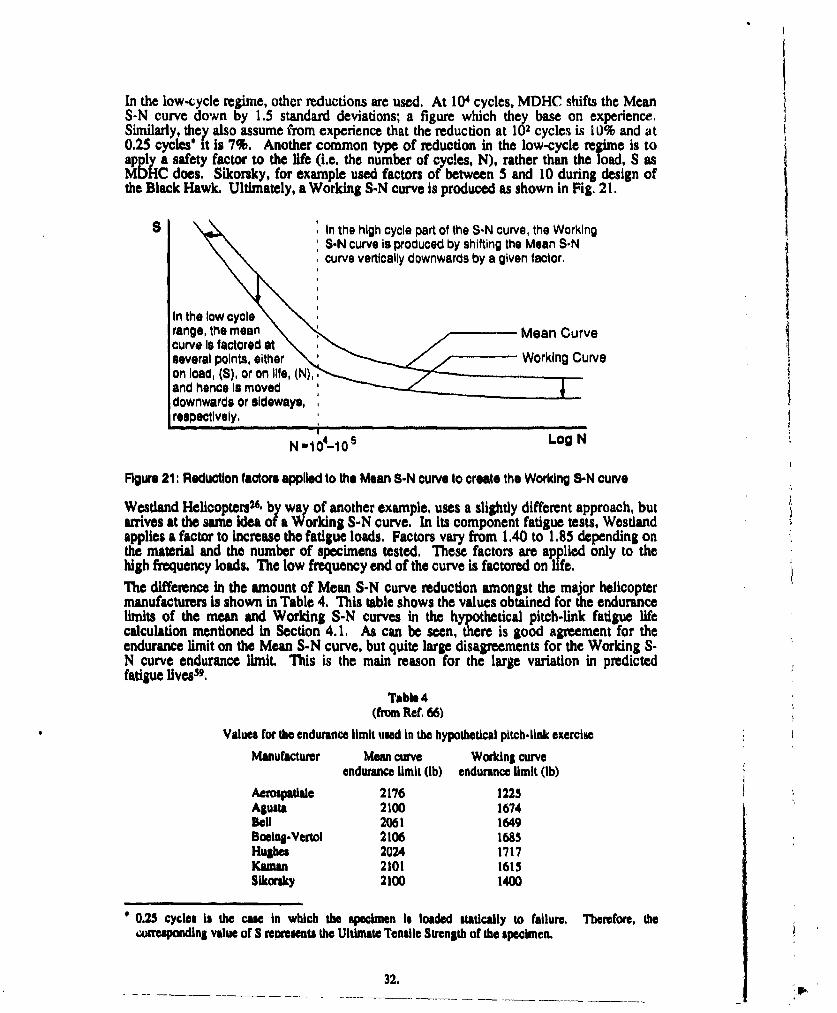
In the low-cycle regime, other reductions are used. At 104 cycles, MDHC shifts the MeanS-N curve down by 1.5 standard deviations; a figure which they base on experience.Similarly, they also assume from experience that the reduction at 102 cycles is 10% and at0.25 cycles' it is 7%. Another common type of reduction in the low-cycle regime is toapply a safety factor to the life (i.e. the number of cycles, N), rather than the load, S asMDHC does. Sikorsky, for example used factors of between 5 and 10 during design ofthe Black Hawk. Ultimately, a Working S-N curve is produced as shown in Fig. 21.
8 In the high cycle part of the S-N curve, the WorkingS-N curve Is produced by shifting the Mean S-Ncurve vertically downwards by a given factor.
In the low cyclerange, the mean Mean Curvecurve Is factored atseveral points, either Working Curveon load, (S), or on life, (N),and hence Is moveddownwards or sideways,respectively.
N -1 0-10 Log N
Figure 21: Reduction factors applied to the Mean S-N curve to create the Working S-N curve
Westland Helicopters 6 by way of another example, uses a slightly different approach, butarrives at the same idea ofa Working S-N curve. In its component fatigue tests, Westlandapplies a factor to increase the fatigue loads. Factors vary from 1.40 to 1.85 depending onthe material and the number of specimens tested. These factors are applied only to thehigh frequency loads. The low frequency end of the curve is factored on life.
The difference In the amount of Mean S-N curve reduction amongst the major helicoptermanufacturers is shown in Table 4. This table shows the values obtained for the endurancelimits of the mean and Working S-N curves in the hypothetical pitch-link fatigue lifecalculation mentioned in Section 4.1. As can be seen, there is good agreement for theendurance limit on the Mean S-N curve, but quite large disagreements for the Working S-N curve endurance limit. This is the main reason for the large variation in predictedfatigue lives59.
Table 4(from Ref. 66)
Values for the endurance limit used in the hypothetical pitch-link exercise
Manufacturer Mean curve Working curveendurance limit (Ib) endurance limit (Ib)
Aerospatliale 2176 1225Agusta 2100 1674BClH 2061 1649Boeing-Vertol 2106 1685Hughes 2024 1717Kaman 2101 1615Sikorsky 2100 1400
0.25 cycles is the case in which the gpeci•mnn is loaded statically to failure. Therefore, the•orresponding value of S relmosents the Ultimate Tensile Strength of the specimen.
32.
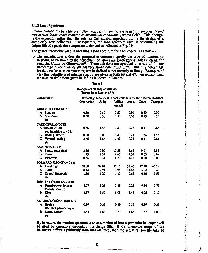
4.1.2 Load Spectrum"Without doubt, the best life predictions will result from tests with actual components andtrue service loads under realistic environmental conditions", writes Och5 6. This, though,is the exception rather than the rule, as Och admits, especially during the design of acompletely new helicopter. Consequently, the load spectrum used in determining thefatigue life of a particular component is derived as indicated in Fig. 19.
The general procedure used in obtaining a load spectrum for a helicopter is as follows:
(i) The manufacturer and/or the prospective customer specify the type of mission, ormissions, to be flown by the helicopter. Missions are given general tidtes such as, forexample, Utility or Observation' 3. These missions are specified in terms of "... thepercentage breakdown of all possible flight conditions ... "56. and this percentagebreakdown (or mission spectrum) can be defined either coarsely or finely. Examples ofvery fine definitions of mission spectra are given in Refs 63 and 67. An extract fromthe mission definitions given in ReWf. 63 is shown in Table 5.
Table 5
Examples of Helicopter Missions(Extract from Ryan at a163)
CONDITION Percentage time spent in each condition for the different missionsObservation Utility Utility/ Attack Crane Transport
AssaultGROUND OPERATIONS
A. Start-up 0.50 0.50 0.50 0.50 0.50 0.50B. Shut-down 0.50 0.50 0.50 0.50 0.50 0.50
etcTAKE-OFF/LANDING
A. Vertical lift-off 2.66 1.58 0.43 0.22 0.51 0.66and transition to 40 kn
B. Rolling take.off 0.00 0.00 0.43 0.27 1.24 1.53C. Vertcal landing 2.66 1.58 0.43 0.22 0.51 0.66
etcASCENT (>40 kn)
A. Steady-statb climb 8.36 9.00 10.35 3.66 9.91 9.83B. Turns 1.45 2.32 4.65 4.34 0.65 0.99C. Pushovers 0.34 0.34 1.23 1.16 0.00 0.00
FORWARD FLIGHT (>40 kn)A, Level flight 38.08 39.02 30.13 33.40 47.58 46.28B. Turns 8.14 9.91 10.26 11.65 3.02 3.43C, Control Reversals 1.50 1.27 1.13 0.63 0.10 1.51
etcDESCENT (Power on, > 40kn)
A. Partial-power descent 2.07 5.26 3.18 2.21 9.10 7.79(Steady descent)
B. Dive 3.37 3.50 5.09 3.45 0.05 2.12etc
AUTOROTATION (Power off)A. Entries 0.39 0.39 0.39 0.39 0.39 0.39
(Includes power chops)B. Steady descent 1.63 1.63 1.63 1.63 1.63 1.63
etc
By its nature, the mission spectrum is an assumption of how a particular helicopter willbe used by operators throughout its design life. If the in-service usage of thehelicopter differs significantly from that assumed, then the actual fatigue life may be
33.
significantly altered. If the helicopter is a derivative of an existing design, then themanufacturer may have a good idea of the type of usage to expect. On the other hand,for a new helicopter, the "... definition of the operational spectrum ... normally ismade many years in advance of its entry into service, and changes in usage couldoccur in the interim and have a tremendous impact on the calculated fatigue life ... it,McDermott et al6g. Also, the definition "... should provide the broad [load] spectra ineach role ... [but] ... the helicopter is a versatile creature and can be used in a widevariety of roles many of which may be devised lon$ after the specification [of the loadspectral was prepared and the aircraft is in service
(ii) The loads acting at each of the flight conditions specified in the mission spectrum mustbe obtained' 3. There are two ways in which this can be accomplished. The firstmethod is used for a new helicopter design and consists of a combination of analysisand the knowledge of the helicopter designer in knowing the types of relevant loadingactions. These loads are determined in general terms (e.g. lift, drag, and c.g.accelerations).The forces thus determined are then converted to loads which are specific to aparticular component. These loads are given in a form which specifies the mean andalternating loads (or equivalents such as maximum and minimum loads) and the loadingfrequencies.The second method involves using strain gauges to measure component loads in-flightand is an option if the helicopter is a derivative of an existing design. This may or maynot be done, however, depending on how radical are the changes. If the changes areminor, then the designers can be confident that they know the significant loads and sothe need to perform flight tests will then be based on cost and time factors.Flight testing is always used, though, to verify the loads used in the design of a newhelicopter. Once a prototype is available for flight testing then a flight loads survey isconducted in which the helicopter is flown through some of the flight conditionsspecified in the mission spectrum so that corrsponding component loads can bemeasured. The reason that not all of the mission spectrum is covered in the flight loadssurvey is due to time and cost constraints35 . The flight test engineers attempt to ensurethat at least all the most critical flight conditions are included as well as some of thenon-critical ones. Due to physical constraints, not all components of interest can beinstrumented with strain gauges, so the manufacturer must determine the relationshipsbetween the loads in the instrumented and uninstrumented components. This is usuallydone by testing of the appropriate component assemblies in static test fixtures.
(iii) In general, the stress ratio, R' , of the loads found in (ii) will not correspond with thatof the Working S-N curve. If the spread of flight load R values is not large "... arepresentative stress ratio can be assumed for both fatigue test and flight test data,and no further correction is required... "6,. If this is not the case, then some type ofcorrection (also known as a reduction) must be applied to the flight loads to makethem consistent with the Working S-N curve. Noback53, indicates that the mostcommon type of mean load correction is the use of the Modified Goodman (orSoderberg) diagram. That is, the damage caused by a cyclic load, S at a mean load,Sin is equivalent to the damage caused by a cyclic load s at a mean load, S. , whereSd would be the mean load applicable to the Working S-N curve. However, somemanufacturers act conservatively and only apply this correction If S,,z > S .Reference 57 shows how Augusta uses the Goodman correction.
(iv)The loads in (iN) are combined with the mission spectrum in (i) to produce the loadspectrum for a particular component. The load spectrum is expressed either inpercentages of time spent in each flight condition as shown in (i) and/or as the numberof occurrences in a given time period (per hour, for example).
R, the stres ratio for a load cycle, is equal to the minimum stress divided by the maximum asress in thecycle.
34.
4.1.3 Damage Hypothesis
Once the load spectrum and the Working S-N curve have been derived, they are combinedby means of a damage hypothesis to obtain a safe-life (i.e. a retirement life) for acomponent. The hypothesis which is universally used in the helicopter industry is Miner'sCumulative Damage Hypothesis, also known as the Palmgren-Miner Cumulative DamageHypothesis or, simply, Miner's Rule. The basic method is as follows:'
(i) Select a flight condition from the mission spectrum and hence obtain thecorresponding load, Sj
(ii) Determine the number of cycles, N,, from the Working S-N curve, available at loadlevel Si before component safe-life is expended.
(iii) Determine the number of occurrences, n1 , of load S, in the load spectrum for a giventime period (say one hour)
(iv) Define the fatigue damage due to load Sj as ni IN/ per hour
(v) Repeat steps (i) to (iv) for the other loads in the load spectrum
(vi) If there are k loads in the spectrum, then the total fatigue damage, D, induced in thecomponent is:
k
D = E ( n1 IN1) per hour
(vii) The safe-life of the component is then the reciprocal, i.e. Safe-Life = 1D hoursMiner's Rule, however, is known to have the undesirable trait of sometimes producingunconservative results. It does not, for example, take into account the possible retardationor acceleration effects that large load cycles can have on crack growth70.71. This isespecially important in helicopters because they are loaded by a mixture of low magnitude,high frequency loads, and large magnitude, low frequency loads. The high frequency loadsare mostly below the endurance limit and are therefore ignored by Miner's rule. However,the application of the large magnitude loads can cause the endurance limit to decrease andhence allow the high frequency loads to become damaging (see Section 3.4.3). To offsetthis, some manufacturers apply a reduction factor to the life calculated in (vii) above for acomponent if large magnitude, low frequency loads are thought to be important26,53,3 7,62 .For example, both Agusta37 and the American FAA60 use the following reductions:
0 If the calculated fatigue life is less than 3350 hours, the service life is 0.75 times thecalculated life.
0 If the calculated fatigue life is greater than 3350 hours, the service life is 0.375 timesthe calculated life plus 1250 hours.
Westland, on the other hand, applies a factor of 0.75 to all component fatigue lives toarrive at the safe-life.
Despite all the shortcomlngs, the use of Miner's rule has been generally successful becauseof the vast experience in its application built up since the 1940s along with the use ofappropriate empirical correction factors.
4.1.4 Cycle Counting Methods
In Section 4.1.3, it was stated that, to use Miner's Rule, the number of occurrences, nj, ofload S, must be found. This Section details the three methods which are currently in use.Assume, for purposes of discussion, that a flight loads survey revealed that during aparticular flight condition (call it X), the load time history experienced by a particular
"The method shown assumes that the block counting method is used. However, it is also applicable toother counting schemes in which case a flight condition may have several sets of Sj, N1, and nj values.
35.
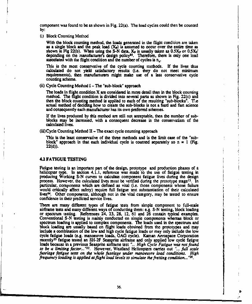
component was found to be as shown in Fig. 22(a). The load cycles could then be countedby:(i) Block Counting Method
With the block counting method, the loads generated in the flight condition are takenas a single block and the peak load (Xp) is assumed to occur over the entire time asshown in Fig 22(b). When using the S-N data, Xp is usually taken as 0.5Xp or 0.SXpdepending on the manufacturer's design policyi. Therefore, there is only one loadassociated with the flight condition and the number of cycles is n,.
This is the most conservative of the cycle counting methods. If the fives thuscalculated do not yield satisfactory results (i.e. they do not meet minimumrequirements), then manufacturers might make use of a less conservative cyclecounting scheme.
(ii) Cycle Counting Method I - The "sub-block" approachThe loads in flight condition X are considered in more detail than in the block countingmethod. The flight condition is divided into several parts as shown in Fig. 22(c) andthen the block counting method is applied to each of the resulting "sub-blocks". 1.eactual method of deciding how to create the sub-blocks is not a hard and fast scienceand consequently each manufacturer has its own preferred schemes.If the lives produced by this method are still not acceptable, then the number of sub-blocks may be increased, with a consequent decrease in the conservatism of thecalculated lives.
(iii) Cycle Counting Method Il -The exact cycle counting approachThis is the least conservative of the three methods and is the limit case of the "sub-block" approach in that each individual cycle is counted separately so n = I (Fig.22(d)).
4.2 FATIGUE TESTING
Fatigue testing is an important part of the design, prototype and production phases of ahelicopter type. In section 4.1. 1, reference was made to the use of fatigue testing inproducing Working S-N curves to calculate component fatigue lives during the designprocess. However, the calculated lives must be verified during the prototype stage'3. Inparticular, components which are defined as vital (i.e. those components whose failurewould critically affect safety) require full fatigue test substantiation of their calculatedfives". Other components, although not in the vital category, may be tested to ensureconfidence in their predicted service lives.
There are many different types of fatigue tests from simple component to full-scaleairframe tests and many different ways of conducting them: e.g. S-N testing, block loadingor spectrum testing, References 24, 23, 28, 12, 61 and 26 conltain typical examples.Conventional S-N testing is mainly conducted on simple components whereas block orspctrum loading is applied to complex components. The loads used in the spectrum andblock loading are usually based on flight loads obtained from the prototypes and mayinclude a combination of the low and high cycle fatigue loads or may only include the lowcycle fatigue loads (e.g. manoeuvre loads, GAG cycle). Kaman Aerospace Corporationrecently 23 fatigue tested an SH..2F Seasprite airframe and only applied low cycle fatigueloads becauso in a previous Seasprite airframne test "... High Cycle Fatigue was not foundto be a limiting factor... ''2. However. We3tand Helicopters carries out "... full scalefuselage fatigue tests on the whole fuselage under manoeuvre load conditions. Highfrequency loading is applied at flight load levels to simulate the fretting condition... ,s.
36.
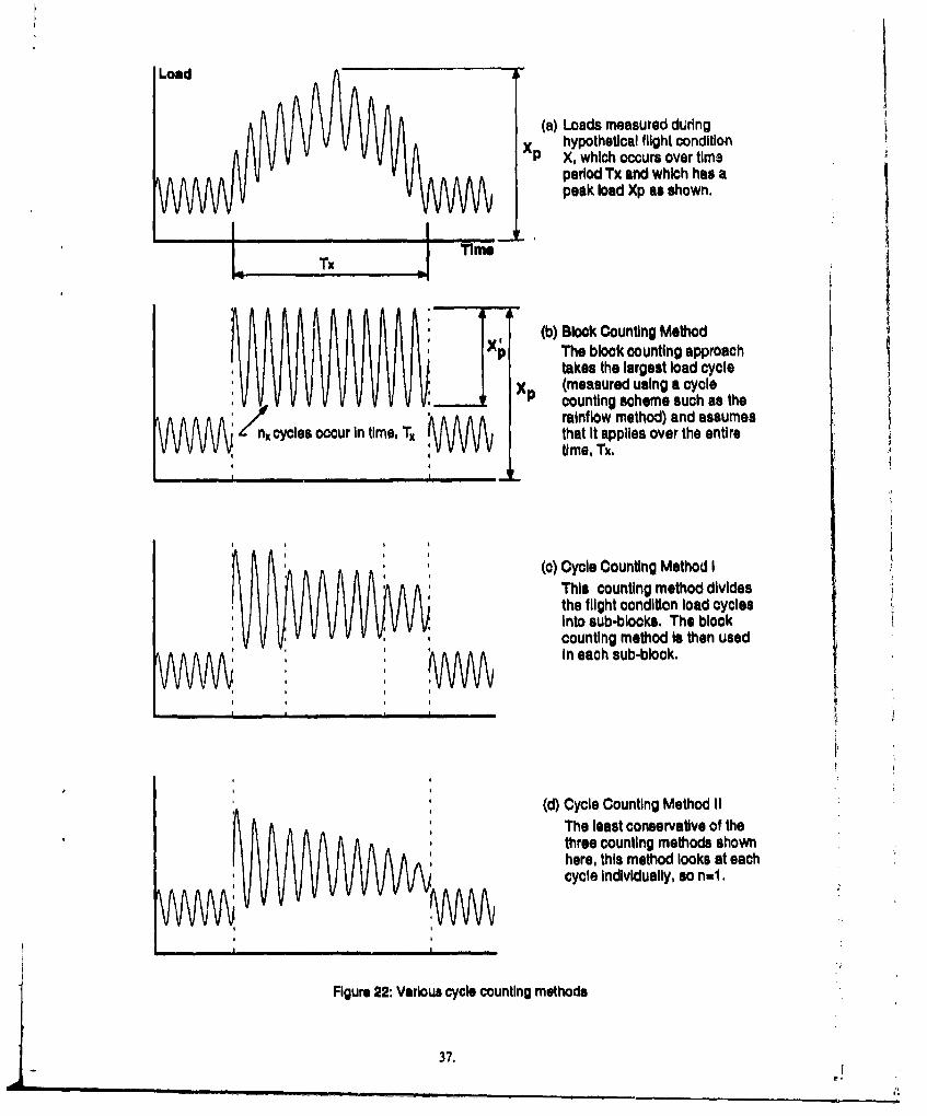
Load
(a) Loads measured duringhypothetical flight condition
X p X, which occurs over time
period Tx and which has apeak load Xp as shown,
T'"J TimeTx
(b) Block Counting MethodSxlý The block counting approach
takes the largest load cycle(measured using a cyclecounting scheme such as the
/ A A minrainflow method) and assumesXx cycles occur In time, Tx that It applies over the entire
:W time, Tx.
(C) Cycle Counting Method IThis counting method dividesthe flight condition load cyclesInto sub-blocks. The blockcounting method Is then usedin each sub-block.
* i
(d) Cycle Counting Method IIThe least conservative of the
* ithree counting methods shownhere, this method looks at eachcycle Individually, so n=1
Figure 22: Various cycle counting methods
37,
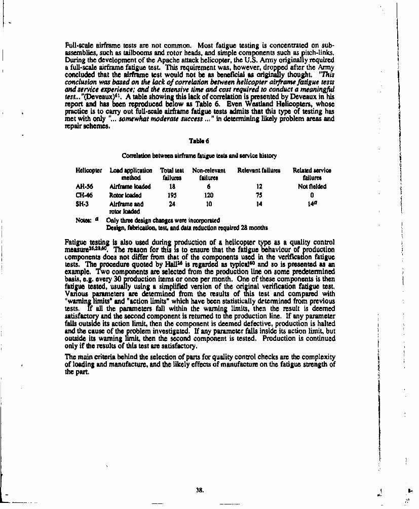
Full-scale airframe tests are not common. Most fatigue testing is concentrated on sub-assemblies, such as tailbooms and rotor heads, and simple components such as pitch-links.During the development of the Apache attack helicopter, the U.S. Army originally requireda full-scale airframe fatigue test. This requirement was, however, dropped after the Armyconcluded that the airframe test would not be as beneficial as originally thought. "Thisconclusion was based on the lack of correlation between helicopter airframe fatigue testsand service experience: and the extensive time and cost required to conduct a meaningfultest... "(Deveaux)dl. A table showing this lack of correlation is presented by Deveaux in hisreport and has been reproduced below as Table 6. Even Westland Helicopters, whosepractice is to carry out full-scale airframe fatigue tests admits that this type of testing hasmet with only "... somewhat moderate success .. " in determining likely problem areas andrepair schemes.
Table 6
Correlation between airframe fatigue tests and service history
Helicopter Load application Total test Non-relevant Relevant failures Related servicemethod failures failures failures
AH.36 Airframe loaded 18 6 12 Not fielded
C'-46 Roto loaded 195 120 75 0SH-3 Airframe and 24 10 14 14a
rotor loadedNotes: a Only three design changes were incorporated
Design, fabrication, test, and data reduction required 28 months
Fatigue testing is also used during production of a helicopter type as a quality controlmeasure, 2 sMAO. The reason for this is to ensure that the fatigue behaviour of productioncomponents does not differ from that of the components used in the verification fatiguetests. The procedure quoted by H&1126 is regarded as typicalse and so is presented as anexample. Two components are selected from the production line on some predeterminedbasis, e.g. every 30 production items or once per month. One of these components is thenfatigue tested, usually using a simplified version of the original verification fatigue test,Various parameters are determined from the results of this test and compared with"warning limits" and "action limits" which have been statistically determined from previoustests. If all the parameters fall within the warning limits, then the result is deemedsatisfactory and the second component is returned to the production line. If any parameterfalls outside its action limit, then the component is deemed defective, production is haltedand the cause of the problem investigated. If any parameter falls inside its action limit, butoutside its warning limit, then the second component is tested. Production is continuedonly if the results of this test are satisfactory.
The main criteria behind the selection of parts for quality control checks are the complexityof loading and manufacture, and the likely effects of manufacture on the fatigue strength ofthe part.
38.
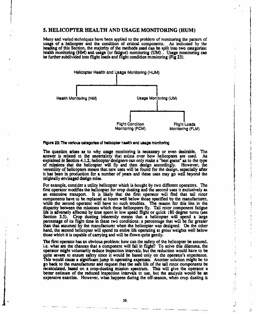
5. HELICOPTER HEALTH AND USAGE MONITORING (HUM)
Many and varied techniques have been applied to the problem of monitoring the pattern ofusage of a helicopter and the condition of critical components. As indicated by theheading of this Section, the majority of the methods used can be split into two categories:health monitorin; (HM) and usage (or fatigue) monitoring (UM). Usage monitoring canbe further subdivided into flight loads and flight condition monitoring (Fig 23).
Helicopter Health and Usage Monitoring (HUM)
I II I I I I I
Health Monitoring (HM) Usage Monitoring (UM)I
Flight Condition Flight LoadsMonitoring (FCM) Monitoring (FLM)
Figure 23: The various categories of helicopter health and usage monktoring
The question arises as to why usage monitoring is necessary or even desirable. Theanswer is related to the uncertainty that exists over how helicopters are used. Asexplained In Section 4.1.2, helicopter designers can only make a "best guess" as to the typeof missions that the helicopter will fly and then design accordingly, However, theversatility of helicopters means that new uses will be found for the design, especially afterit has been in production for a number of years and these uses may go well beyond theoriginally envisaged design roles.For example, consider a utility helicopter which is bought by two different operators. Thefirst operator modifies the helicopter for crop dusting and the second uses it exclusively asan executive transport. It is likely that the first operator will find that tail rotorcomponents have to be replaced at hours well below those specified by the manufacturer,while the second operator will have no such troubles. The reason for this lies in thedisparity between the missions which these helicopters fly. Tail rotor component fatiguelife is adversely affected by time spent in low speed flight or quick 180 degree turns (seeSection 3.5). Crop dusting inherently means that a helicopter will spend a largepercentage of its flight time in these two conditions: a percentage that will be far greaterthan that assumed by the manufacturer when the helicopter was designed. On the otherhand, the second helicopter will spend its entire life operating at gross weights well belowthose which it is capable of carrying and will be flown quite gently.The first operator has an obvious problem: how can the safety of the helicopter be assured,i.e. what are the chances that a component will fail in flight? To solve this dilemma, theoperator might voluntarily reduce inspection intervals, but the reduction would have to bequite severe to ensure safety since it would be based only on the operator's experience.This would cause a significant jump in operating expenses. Another solution might be togo back to the manufacturer and request that the safe life of the tail rotor components berecalculated, based on a crop-dusting mission spectrum. This will give the operator abetter estimate of the reduced inspection intervals to use, but the analysis would be anexpensive exercise. However, what happens during the off-season, when crop dusting is
39.
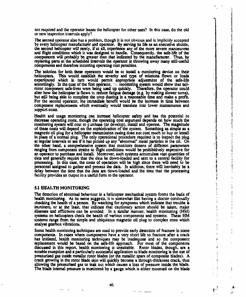
not required and the operator leases the helicopter for other uses? In this case, do the oldor new inspection intervals apply?
The second operator also has a problem, though it is not obvious and is implicitly acceptedby every helicopter manufacturer and operator. By serving its life as an executive shuttle,the second helicopter will rarely, if at all, experience any of the more severe manoeuvresand flight conditions which it was designed to handle. Consequently, the safe-life of thecomponents will probably be greater than that indicated by the manufacturer. Thus, byreplacing parts at the scheduled intervals the operator is throwing away many still-usefulcomponents and therefore incurring operating cost penalties.
The solution for both these operators would be to install a monitoring device on theirhelicopters, This would establish the severity and type of missions flown or loadsexperienced which in turn would permit appropriate adjustment of the safe-lifeaccordingly. In the cuse of the first operator, , monitoring system would show that tail-rotor component safe-lives were being used up quickly. Therefore, the operator couldalter how the helicopter is flown to reduce fatigue damap (e.g. by maig slower turns),but still being able to complete the crop dusting in a reasonable time and make a profit.For the second operator, the immediate benefit would be the increase in time betweencomponent replacements which eventually would translate into lower maintenance andsupport costs,
Health and usage monitoring can increase helicopter safety and has the potential todecrease operating costs, though the operating cost argument depends on how much themonitoring system will cost to p rhase (or develop), install and operate. The magnitudeof these costs will depend on the sophistication of the system. Something as simple as amagnetic oil plug for a helicopter transmission casing does not cost much to buy or installin place of a normal plug. The only operational procedure required is to inspect the plugat regular intervals to see if it has picked up any abnormal" metal particles in the oil. Onthe other hand, a comprehensive system that monitors dozens of different parametersranging from component strains to flight conditions would be prohibitively expensive foran operator to purchase and install. Moreover, such systems accumulate vast quantities ofdata and generally require that the data be down-loaded and sent to a central facility forprocessing. In this case, the costs of operation will be high since there will need to bepersonnel assigned to gather and process the data. In addition, there will inevitably be adelay between the time that the data are down-loaded and the time that the processingfacility provides an output in a useful form to the operator.
5.1 HEALTH MONITORING
The detection of abnormal behaviour in a helicopter mechanical system forms the basis ofhealth monitoring, As its name suggests, it is somewhat like having a doctor continuallychecking the health of a person. By watching for symptoms which indicate that trouble isimminent, or at the least, that indicate that cautionary action should be taken, majorillnesses and afflictions can be avoided. In a similar manner, health monitoring (HKI)systems on helicopters check the health of various components and systems. These HMsystems range from the simple and ubiquitous magnetic oil plug to complex ones whichanalyse gearbox vibrations,
Some health monitoring techniques are used to provide early detection of fracture in somecomponents. In cases where components have a very short life to fracture after a crackhas initiated, health monitoring techniques may be inadequate and so the componentreplacement would be based on the safe-life approach. For most of the componentsdiscussed in this report, health monitoring is unsuitable. Rotor blades, though, are anotable exception and a particularly successful application to blade monitoring is the use ofpressurised gas inside metallic rotor blades (or the metallic spars of composite blades). Acrack growing in the rotor blade skin will quickly become a through-thickness crack, thusallowing the pressurised gas to leak out which causes a loss of pressure inside the blade.The blade internal pressure is monitored by a gauge which is either mounted on the blade
40.
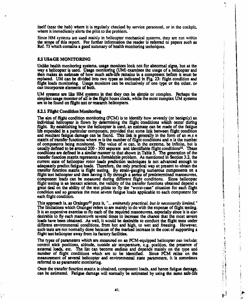
itself (near the hub) where it is regularly checked by service personnel, or in the cockpit,where it immediately alerts the pilot to the problem.Since HM systems are used mainly in helicopter mechanical systems, they are not withinthe scope of this report. For further information the reader is referred to papers such asRef. 73 which contains a good summary of health monitoring techniques.
5.2 USAGE MONITORINGUnlike health monitoring systems, usage monitors look not for abnormal siin, but at theway a helicopter is used. usage monitoring (UM) examines the usage of a helicopter andthen makes an estimate of how much safe.Ufe remains in a component before it must bereplaced. UM can be divided into two types as indicated in Fig. 23: flight condition andflight loads monitoring. Usage. monitors can be exclusively of one type or the other, orcan incorporate elements of both.
UM systems are like HM systems In that they can be simple or complex. Perhaps thesimplest usage monitor of all is the flight hours clock, while the most complex UM systemsare to be found on flight test or research helicopters.
5.2.1 Flight Condition MonitoringThe aim of flight condition monitoring (FCM) is to identify how severely (or benignly) anindividual helicopter is flown by determining the flight conditions which occur duringflight. By establishing how the helicopter is used, an estimate can be made of the fatgellife expended In a paicular component, provided that some link between flight condi onand resultant fatigue damage can be found, This link is generally in the form of an m x nmatrix of transfer functions where m is the number of flight conditions and n is the numberof components being monitored. The value of m canTin the extreme, be Infinite, but isusually defined to be around 200 300 separate and identifiable flight conditions32 . Theseconditions are defined in a similar manner to that shown in Table 5. The generation of thetransfer function matrix represents a formidabl problem. As mentioned in Section 3.2, thecurrent state of helicopter rotor loads prediction techniques is not advanced enough toadequately predict fatigue loads. Therefore, the only practical way at present to obtain thetransfer function matrix is flight testing. By strain-gauging numerous components on aflight test helicopter and then having it fly through a series of predetermined manoeuvres,component loads can be measured during different flight conditions. Since helicopterflight testing is an inexact science, the validity of the transfer functions obtained depend agreat deal on the ability of the test pilots to fly the "worst-case" situation for each flightcondition and so generate the most severe fatigue loads applicable to each component foreach flight condition.This approach is, as Grainser32 puts it, ... eminently practical, but is necessarily limited.,The limitations which Grainger refers to are mainly to do with the expense of flight testing.It is an expensive exercise to fly each of the required manoeuvres, especially since it is alsodesirable to fly each manoeuvre several times to increase the chance that the most severeloads have been obtained. As well, it would be desirable to conduct the flight tests underdifferent environmental conditions, from hot and high, to wet and freezing. However,such tests are not normally done because of the marked increase in the cost of supporting aflight test helicopter away from its factory facilities.The types of parameters which are measured on an FCM-equipped helicopter can include:control stick positions, altitude, outside air temperature, c.g. position, the presence ofexternal loads, etc. The list can become endless and depends mainly on the type andnumber of flight conditions which are to be identified. Since FCM relies on themeasurement of several helicopter and environmental state parameters, it is sometimesreferred to as parametric monitoring.Once the transfer function matrix Is obtained, component loads, and hence fatigue damage,can be estimated. Fatigue damage will normally be estimated by using the same safe-life CI
41.
techniques as discussed in Section 4. A diagrammatic representation of how a typicalFCM system works is shown in Fig. 24.
SRead StrainCacltLod. GaugesCaultLod
Calulate Lo"ds in Ja aclt a igu
Figure 24: Sequence of events In a flight condition monitoring system. T represents a matrix of
transfer functions.
An example of an ICM system which was developed for the U.S. Army during the late1970s, early 1980s, but not put into operation Is the Structural Integrity Recording System(SIRS)7 4's75,7. Another system, this time developed for the US, Navy and currently (erly1992) being tested on an AH-lW Cobra Is the Structural Data Recording Set (S RS)77.This system is made by Systron Donner, a division of THORN EMI, and is scheduled toenter full-scale production in 1993. Current phlans call for the SDRS system to be installedon all fixed and rotary-wing aircraft in the U.S, Navy inventory.
52.2 Flight Loads MonltoringFli ht loads monitoring (FLM) is similar to FCM in that they both attempt to quantify in-fl t fadtiue damage. Unlike 1CM, however, FLM does not rely on indirect methods todetermine loads, but on the output from strain gauges which are mounted on several keycomponents. Transfer functions are still used, though, to estimate the loads oncomponents that are either impractical, inaccessible, or not necessary to strain gauge. Adiagrammatic representation of FLM is shown in Fig. 25.
Estimate otherparamoters as
Identify Flight Caloulate FatigueCondition Damage
Figure 25: Sequence of events In a flight loads monitoring system. T represents a matrix oftransfer functions.
The components which are strain gauged a mainly those in the rotating system sincethe-, are the ones most prone to fatigue failures. This immediately means that the strain&&auV, signals must be transferred from the rotating system to the fixed system (i.e. the
-irframe) since that is where the recording and analysis system would be located. This hasbeen achieved either through the use of slip rinpg9,78 or radio telemetry. As Holford39
42.
point; out, these methods may be acceptable on flight test and research helicopters, butthey are likely to cause maintenance problems on in-service aircraft.Once the strains have been acquired, they are converted to loads. These loads are thenused to derive loads in non-strain-gauged components via the use of transfer functions.Aftr this, the fatigue damage is determined In the same way as is done in an FCM system.PLM has been restricted to applications involving testing and research because of theproblems associated with transferring strain gauge signals across from the rotating systemto the airframe. However, there are other approaches to ELM which use indirectmeasuring techniques similar to those used for PCM. Rotating component loads can bededuced from airframe load measurements. By mounting strain gauges only on airframecomponents, .the need for dip rings is eMrnated, The penalty incurred is that now yetanother set of transfer functions must be found which i loads in the fixed system toloads in the rotating system. Such an approach has been tried by the Canadimfn72 withsome success and is currently being Investigated by Kaman Aerospace 7g"2 under contractto the U.S. Army.Another method being investigated by the U.S. Army is an FLM system known as SIMS(Smart Integrated Ncrosensor System)'0 . SIMS essentially consists of a self containedstrain-gauge and micro-processor unit which will be permanently attached to any desiredcomponent. The strain gauge signals are fed directly to the microprocessor which is pre-programmed with a cycle-counting scheme and a safe-life analysis to determine fatiguedamage. The unit will have some type of display which will indicate the percentage of lifeexpended. This is different to most FLM systems in that the input data ame processed on-board and the only output is a single number - the percentage of safe-life expended.
5.2.3 Flight Condition versus Flight Loads MonitoringThe following list summarises some of the advantages and disadvantages of the twosystems.* FCM is, in a sense, compatible with the way that a helicopter is designed. As shown in
Section 4, a helicopter design is based on a mission which is defined In terms of thepercentage time spent in various flight conditions and not in terms of component loads.
* The amount of conservatism in FCM depends critically upon the transfer functionswhich convert flight condition to component loads. If the flight tests do not achieve themost damaging conditions for each flight condition, then the transfer functions will yieldlow component loads under some circumstances. The chances of this happeningdepend on the experience of the test pilots and flight test engineers. The main way ofcounteracting this is by using safety factors in the safe-life calculations.
* By using strain readings, .LM systems eliminate the uncertainty of the FCM transferfunctions. Strain gauges can be mounted on components such that they read thenominal component strain and then an appropriate stress concentration factor can beapplied to give peak strains. The amount of uncertainty in detecting peak loads is lessas is the possibilty of error in the transfer functions needed to deterne loads in non-strain-gauged components.
A high-fidelity flight regime recognition algorithm is essential for FCM systems. Thealgorithm must be capable of recognising all the .required flight conditions. However,the recognition of low speed manoeuvres in particular has always been difficult. Thisproblemnis yet to be adequately addressed.
* An PCM system should be easier and lu expensive to install than an equivalent ELMsystem, This comes about because some of the required inputs for an ECM system arenonnally already available in a usable form. In modern helicopters, with digitalautomatic flight control systems (AECS), most of the required input parameters areread by the AFCS so an PCM systm can tap in" to the APCS wiring and read theexisting signals. ELM systm require the installation of strain gaues and these have tobe installed with care. If the ELM system has strain gauges mouated on rotating
43.
components, extra care needs to be taken in mounting the gauges. In addition somemeans, such as slip rings, must be provided to bring the strain gauge signals down to theairframe (i.e. the fixed system).
SSutain gauge signals can become corrupted by electrical noise as they are transferredacross slip rings so this requires the addition of filters or error correction software toreduce the amount of bad data.
0 Routine rotor head maintenance of helicopters equipped with an FLM system willbecome more complicated because of the presence o strain gauges and slip rings.P FCM systems can provide a history of how the helico ter was used in a way that iseasily Understood, e.gee . times in various fl1gt conditions and the resultincomponent loads. Such knowledge is useful in setting up mission spectra for newderivative helicopte ds but it is espc y ueful for helicopter operators. Bybeing able to correlate actl usage with fatigu damage, operators have the chance toalter their usage to minimise damage and hence operating costs.FLM systems can produce a spectrum of the loads experienced by a particularcomponent. This Information can be useful to helicopter designers.
* Some FLM systems that are currently being researched propose doing away with straingauges in the rotating system and have them only in the fixed system. This reduces theexpense of an FLM system, but introduces another level of calculation (and uncertainty)Into the process by having to determine rotating system loads from fixed system loads
5.2A Which System?There is no clear-cut answer as to whether flight condition or flight loads monitoring Isbetter, or whether a hybrid system, combining aspects of both FCM and FLM shouldibeused. The decision on what to use depends on the reasons behind the proposedmonitoring program. For example:* What are the aims of the monitoring program? That is, is the monitoring program
meant to give insight into how a helicopter, or fleet of helicopters, is flown? Perhaps itis meant to validate calculated fatigue lives in a new design, or maybe to modify existingcomponent replacement times?h Isthe system going to be installed on a number of helicopters or only on a research ortest vehicle?
h Is the direct measurement of flight loads important or ame indirect methods acceptable?* Do the measured data have to be stored, i.e. is a recorded history (either loads or flight
condition) necessary?h Is a correlation of flight condition with component loads required?
• Will the monitoring system process all the input data onboard or will the data have to besent somewhere for processing?
The answers to these questions will provide the basis for choosing the type of system thatshould be used and its level of sophistication.If only one component on a helicopter is of concern then it would be an overkill to install acomplete PCM and "LM system. A simple FLM or FCM system would suffice. Forinstance, when engine transmission shafts on U.S. Army CH-47D Chinooks wereexperiencing fatigue failures the problem was thought to be excessive variation in engine !torque; so a simple system, consisting of a one-channel recorder, was installed to monitorandrecord engine torque. The results of this investigationst showed that engine toique didindeed vary and by a substantial amount. On the other hand, a prototype or researchhelicopter will probably need to have a combined FCM and FLM system.
44..
For a monitoring program designed to more effectively use a fleet of helicopters, a systemincorporating FCM would be better for three main reasons:(i) Current FLM stems would be more troublesome in terms of maintenance and
operation a -xplalned previously. If systems such as the one being studied by KarmanAerospace9 are successfully developed, then these penalties will be substantiallyreduced.
(ii) The expense involved with installing and maintaining an PCM system would, in mostcases, be less than an "LM system. This becomes important when the system is to bedeployed on many helicopters.
(ili)The results obtained from an FCM system would be more useful to the fleet operatorsince they can be directly related to how the helicopters are flown.
5.2. What to monitor?(a) An FCM system would need, as a minimum, the following inputs:
* Airspeed: slow speed and high speed fl3$ht are particularly damaging flight regimes.* Weight: high gross weight flights will incur more fatigue damage.* Pressure Altitude and Outside Air Temperature: gross weight and true airspeed
cannot be determined unless these two parameters are known.* Centre of gravity position: adverse c.g. positions accentuate fatigue damage.* Collective and cyclic stick positions: required to determine the type of manoeuvre.0 Vertical acceleration: required to determine the type of manoeuvre. *
* Main rotor RPM: measurement of this will indicate when a GAG cycle occurs.* Yaw rate: high yaw rates and yawed flight are damaging to tail rotor components.Depending on how fine the separation of recognisable flight conditions is, otherparameters such as pitch and roll rate, lateral and longitudinal acceleration, tail rotorpedal position, ete, might be required.If the FCM system is to also monitor the usage of mechanical components, then otherparameters, such as engine torque, would need to be added to the minimum list shownabove.
(b) An FLM system only monitors strains so the only input requirements are strain gaugesignals. It is not possible to give a definitive list of components to monitor since thisdepends on the exact nature of the load paths In the structure. However, somegenerallsations may be made about whare to moun•t strain Saugea:"* Rotor system components will have much shorter fatigue design lives than airframe
componeuts. Table 7 is a list of the fatigue.critical components on an AH-64AApache and, of the 21 items listed, 20 are from the rotor system. Hence, if fatigueproblems occur In a helicopter, they are more likely to mmyifest themsolves in therotor system. The actual components to strain-gauge m the rotor syster, willdepend upon their relative fatigue lives, their iniportance to flight safety and the easewith which they can be accessed in order to apply the surain gauges.
"* Lift frames c€my the enthi weight of the airframe and payload during flight so theymay be candidates for smtain-gauging.
" Many heicopters are- designed such that their main rotor gearbox (MRGB) housingsx- part o, the airframe structure. This means that the housings are a link in theload path from the rotors to the airframe. The points where the airfrme attaches tothe MRGB housing are, therefore, possible sites for fatigue cracking.
45.
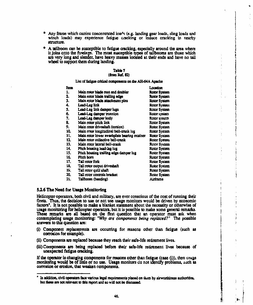
* Any frame which carries concentrated loaN• (e.g. landing gear loads, sling loads andwinch loads) may experience fatigue cracking or induce cracking in nearbystructure.
A ilboom can be susceptible to fatigue cracking, especially around the area whereit joins onto the fuselage. The most susceptible types of tailbooms are those whichare very long and slender, have heavy masses located at their ends and have no tailwheel to support them during landing.
Table 7(fom Re. 82)
List of fatigue critical components on the AH.64A Apache
Item Location2. Main rotor blade mot and doubler Rotor System2. Main rotor blade r•o• end e Roo System3. Main rotor blade attachmant pins Rotor System4. Lead-Lag link Rotor System5. Lead-Lag link damper lugs Rotor System6. Lead-LA damper trunnion Rotor system7. LeadSLag damper body Rotor system8. Main rotor pitch link Rotor System9. Main rotor driveshaft (torsion) Rotor System10. Main rotor longitudinal bell-crank lug Rotor System11. Main rotor lower swushplate bearing retainer Rotor System12. Main rotor collective bell-crank Rotor System13, Main rotor lateral bell-crank Rotor System14. Pitch houing lead-lag lug Rotor System15. Pitch housing trailing edge damper lug Rotor System16. Pitch horn Rotor System17. Tall rotor fork Rotor System18. Tail rotor output drveshaft Rotor System19. Tall rotor quill shaft Rotor System20, Tail rotor controls bracket Rotor System21. Tallboom (bending) Airframe
5.2.6 The Need for Usage Monitoring
Helicopter operators, both civil and military, are ever conscious of the cost of running theirfleets. Thus, the decision to use or not use usage monitors would be driven by economicfactors. It is not possible to make a blanket statement about the necessity or otherwise ofusage monitoring for helicopter operators, but it is possible to make some general remarks.These remarks are all based on the first question that an operator must ask whencontemplating usage monitoring: "Why arc components being replaced?" The possibleanswers to this question are:
(i) Component replacements are occurring for reasons other than fatigue (such ascorrosion for example).
(l) Components are replaced because they reach their safe-life retirement lives.(ii) Components ame being replaced before their safe-life retirement lives because of
unexpected fatigue cracking.
If the operator is changing components for reasons other than fatigue (case (i)), then usgemonitoring would be of little or no use. Usage monitors do not identify problems, such ascorrosion or erosion, that weaken components.
In addition, civil oPerioru face various legal requirnments plbad on thasm by airworthiness authorities,but these e not relevant to th report and so win not be discussed.
46.
If the operator fids that cases (ii) or (iii), or a mixture of cases (i), (ii), and (iii) apply,then usage monitoring might be of benefit. Case (ii) implies that the helicopter opecator isusing its helicopters less severely than the manufacturer anticipated would be the case. Inthis case, usage monitoring may enable component retirement lives to be extended, thusreducing operating costs, but there is an important caveat attached. That is, if usagemonitoring indicates that components can be operated past the manufacturer's statedretirement lives, then there must be agreement from the manufacturer to do so. This isperhaps an obvious point, but it must be stressed that usage monitoring technology, nomatter how sophisticated, does not give helicopter operators the authority to bypass themanufacturer and decide on component retirement lives by themselves.There are two possible ways in which component safe-lives could be extended. The firstway is to extend the life of a particular component by the same amount across the fleet. Inorder to illustrate this, assume that a pardicuar operator has installed usage monitors on allits helicopters and that the operator is examining the impact of usage on the main rotorshafts which have a manufacturer specified retirement life of 2000 hours. Further, assumethat the results of the usage monitoring show that the rate of main rotor shaft fatiguedamage accumulation across the fleet Is, at worst, 75% of that assumed by themanufactur. This indicates to the operator that there is room to increase the specifiedretirement life without compromising safety. Hence, if the manufacturer agrees, theretirement lives of all main rotor shafts in the fleet could be raised by a conservativeamount, say 15 % ( i.e. 2300 hours). This method of life extension requires a large database of hMormation on the operators fleet usage to ensure that any life extensions are, Infact, conservative.The second way of extending component lives Is to base retirement on an individual usagebasis. That Is, to use the previous example, instead of applying a new retirement life of2300 hours to all the main rotor shafts In the fleet, each helicopter's usage monitor woulddetermine when the shaft on that particular helicopter had expended its safe life andneeded replacing. This could mean that one shaft might be replaced at 2600 hours,another at 2700 hours, yet another at 2750 hours, etc. This life extension philosophy ofreplacing components based on monitored usage represents a radical departure from thecurrent practiie of replacment based on the number of hours flown. However, thisphilosophy is also one that has been widely practised for many years on helicopter enginecomponents.In case (Ill), usage monitoring could be used to determine why the unexpected fatiguecracking is occurring. It is possible that it is happening because the operator is flying amore severe mission than that which the helicopter manufacturer assumed would be thecase. If this is so, then a usage monitor would be able to help by allowing the operator totrack down the flight conditions which are causing the accelerated fatigue damage. Thiswould increase flight safety and also allow the operator the chance to change flight profilesso that the damaging flight conditions am avoided as much as possible.However, the reasons for component replacements only give the operator a tentative ideaabout the usefulness of usage monitoring. The actual need for it would be based on a costand benefits analysis and whether the manufacturer was willing to cooperate. Such ananalysis would need to take into account the value of the components that were beingreplaced for safe-life reasons (cues (iH) and (Hi)) versus the value of components beingreplaced for other reasons (case (i)), the potential reductions in operating costs, the safetyaspects of having a usage monitoring system, and the actual cost of installing andoperating the system,Usage monitoring is a field that will grow in the next few years as operators andmanufacturers strive to reduce helicopter operating costs without compromising safety.
47.
6. CONCLUDING REMARKS
This report presents a review of some of the structural integrity issues relevant tohelicopter fatigue. The important points to emerge from this review are:
8 Helicopter rotor systems accumulate vast numbers of load cycles, ypically more than104 cycles per flight hour unlike rxd-win$ aircraft which generally expernce only ahandful of load cycles per flight hour.
• The amount of time that a helicopter is in a particular flight condition is as important asthe flzht condition itself. Accumulation of fatigue damage is proportional to the timeget Fn the flight condition.
0 The critical fatigue load cases of helicopters differ from those for fixed-wing aircraftbecause helicopters use rotating wings (rotor blades) to generate B&. The rotatingaction of the rotor blades requies that the amount of lift that they produce vary in acyclical manner which is quite unlike the wings on a fixed-wing aircraft hese cyclicvariations in the lift along with the aerodynamic interference between the rotor bladesand the airframe, and the ability of the helicopter to hover, fly backwards or sideways,and take off or land vertically, all conspire to complicate the fatigue loadingenvironment for helicopters.
* The safe-life approach for fatigue design is the method of choice in the helicopterindustry. The high number of aplied load cycles and the single load pathcharacteristics typical of helicopter dynamic components generally preclude the use ofthe safety-by-inspection methods of the durability and damage tolerance approach.
0 Helicopter usage monitoring has hitherto been used for verifig mission spec.tumassumptions or for research. However, it has the potential to improve in-flight safetyand reduce operational and support costs for helicopter operators.

REFERENCES
1. Glen S. Campbell A Survey of Serious Aircraft Accidents InvolvingR. T. C. Lahey Fatigue Fracture, Vol. 1, Fixed-Wing Aircraft, National
Aeronautical Establishment, National Research CouncilCanada, Aeronautical Note NAE-AN--8, April 1983.
2. Glen S. Campbell A Survey of Serious Aircraft Accidents InvolvingR. T. C. Lahey Fatigue Fracture, Vol. 2, Rotary-Wing Aircraft,
National Aeronautical Establishment, National ResearchCouncil Canada, Aeronautical Note NAE-AN-8, April1983.
3. Colin Torkington Helicopter Fatigue, Aircraft, February 1981, pp 14 - 17.
4. Report of the Helicopter Airworthiness Review Panel(HARPJ), Civil Aviation Authority, UK, CAA Paper CAP491, June 1984.
5. Doug Richardson The Illustrated Encyclopaedia of Modern Warplanes,Salamander Books Ltd, 1982.
6. Paul Lambermont Helicopters and Autogyros of the World, Cassel and Co.Anthony Pirie Ltd. Second Edition, 1970.
7. Michael J. Taylor History of Helicopters, The Hamilyn Publishing Group,London, England, 1984.
8. Giorgio Apostolo World Encyclopedia of Civil and Military Helicopters,William Collins Sons and Co Ltd, London, England, 1984.
9. 3. B. de Jonge Loads and Damage Tolerance for Helicopters, NationalAerospace Laboratory NLR, NLR TR 86018L, 14 February1986.
10. R. Canedale An Evaluation of Fatigue Procedures for UK MilitaryAeroplanes, Advisory Group for Aerospace Research andDevelopment, NA70, Paper 7, AGARD-CP-297, March1981.
11. A. A. ten Have Usage Monitoring of Military Helicopters, AmericanHelicopter Society, Fatigue Methodology III, Proceedingsof the National Technical Specialists' Meeting, Scottsdale,Arizona, U.S.A., 3 - 5 October, 1989.
12. W. J. Crichlow The Fatigue and Fall.Safe Program for the CertificationC. J. Buzzetti of the Lockheed Model 286 Rigid Rotor Helicopter,J. Fairchild International Committee on Aeronautical Fatigue, Paper
presented at the 5th I.C.A.F. Symposium entitled,"Aircraft Fatigue - Design, Operational and EconomicAspects", Melbourne, Australia, 24 - 24 May, 1967.
13. Bogdon R. Krasnowskl Design, Analysis and Testing Considerations of Fatigue-Sathy P. Viswanathan Crtical Rotorcraft Components, American HelicopterNorman E. Dowling Society, National Specialists' Meeting on Advanced
Rotorcraft Structures, Williamsburg, Virginia, U.S.A, 25 -27 October 1988.
14. P. B. Hovell Operational and Load Data Required for Service LifeEstimates for Military Aircraft and Helicopters, RoyalAircraft Establishment, RAE Technical Report 74121,August 1974.
15. J. Darts Development of Standardised Fatigue Test LoadD. Schtz Histories for Helicopter Rotors - Basic Considerritions
and Definition of Helix and Felix, Advisory Group forAerospace Research and Development, NATO, Paper 15,AOARD-CP-297, March 1981.
16. K. F. Fraser General Requirements and Techniques for ComponentFatigue Life Substantiation in Australian ServiceHelicopters, Aeronautical Research Laboratory, FlightMechanics and Propulsion Report, PROP-R-187, June1991.
17. Colin Young Lifting Line Predictions for a Swept Tip Rotor Blade,William G. Bousman American Helicopter Society, Proceedings of the 47thThomas H. Maier Annual Forum, Phoenix, Arizona, U.S.A., May 6 - 8, 1991,Francois Toulmay pp 1345 - 1351.Neil Gilbert
18. Report of the Working Group on Helicopter HealthMonitoring, Civil Aviation Authority, UK, CAA Paper85012, August 1985.
19. P. G. Wilby An Investigation into the Influence of Fuselage FlowC. Young Field on Rotor Loads and the Effects of VehicleJ. Grant Configuration, Vertica, Vol. 3, Pergamon Press
Ltd. Great Britain, 1979, pp 79 - 94.
20. G.L. Crouse Theoretical and Experimental Study of UnsteadyJ. G. Leishman Rotor/Body Aerodynamic Interactions, AmericanNaipei Bi Helicopter Society, Proceedings of the 46th Annual Forum,
Washington D.C., U.S.A., May 21 - 23, 1990.
21. T. R. Quackenbush New Vortex/Surface Interaction Methods for theD. B. Bliss Prediction of Wake-Induced Airframe Loads, AmericanC-M. G. Lam Helicopter Society, Proceedings of the 46th Annual Forum,A. Katz Washington D.C., U.S.A., May 21 - 23, 1990.
22. R. L. C. Greaves Full.Scale Fatigue Testing of Components andStructures, K. J. Marsh (ed), Butterworth & Co.(Publishers) Ltd, 1988, pp 77 - 97.
23. Michael A. Bowes SH-2F Airframe Fatigue Test Program, AmericanEdward G. Nagy Helicopter Society, Fatigue Methodology 11, ProceedingsCharles P. Hardersen of the National Technical Specialists' Meeting, Scottsdale,LWri E. Hurst Arizona, U.S.A., 3 - 5 October, 1989.
24. John M. McDermott The Methodology of Fatigue Analysis and Testing-Main Rotor Blade and Hub. Hughes YAH-64Advanced Attack Helicopter, Advisory Group forAerospace Research and Development, NATO, Paper 13,AGARD-CP-297, March 1981.
50. a ,
4.
25. Craig J. Werley Fatigue Evaluation of C/MH-53E Main Rotor DamperThreaded Joints, American Helicopter Society, FatigueMethodology HII, Proceedings of the National TechnicalSpecialists' Meeting, Scottsdale, Arizona, U.S.A., 3 - 5October, 1989.
26. A. D. Hall Helicopter Fatigue Evaluation (The U.K Approach),Advisory Group for Aerospace Research and Development,NATO, AGARD Report No. 674, February 1978, pp 13 -20.
27. H. E, Ue Sueur Helicopter Fatigue - A Civil View, Advisory Group forAerospace Research and Development, NA TO, Paper 8,
AGARD-CP-297, March 1981.
28. F. Liard Fatigue of Helicopters . Tests and Calculations,International Comrittee on Aeronautical Fatigue, Paperpresented at the 4th I.C.A.F Symposium entitled "FatigueDesign Procedures", Munich, Germany, 16 - 18 June 1965.
29. F. Liard Fatigue of Helicopters • Service Life EvaluationMethods, Advisory Grouj I•)r Aerospace Research andDevelopment, NATO, AGARD Report No. 674, February1978, pp 54 - 69.
30 James P. Renna Improvements to the Fatigue Substantiation of the H-60Composite Tall Rotor Blade, American HelicopterSociety, Fatigue Methodology III, Proceedings of theNational Tehiemlcl Specialists' Meeting, Scottsdale,Arizona, U.S.A., 3 - 5 October, 1989.
31. R. L. Maltby Preliminary Analysis of Some Operational FlightW. D. Hicks Records on a Sea King Helicopter Engage on Training,
Royal Aircrqft Establishment, RAE Techncal Publication,July 1985.
32. P. S. Grainger Helicopter Data Acquisition in WHL, Advisory Group forAerospace Research and Development, NATO, Paper 12,AGARD Structure and Materials Panel Specialists' Meeting,Siena, Italy, 1984.
33. Malcolm F. Symonds Personal Communication, 11 July 1991, Melbourne,Australia.
34. Jim Kieras Helicopter Surveillance - A look at Current andProposed Future ProgramE, American Helicopter Society,Fatgue Methodology RI, Proceedings of the NationalTechnical Specialists' Meeting, Scottsdale, Arizona, U.S.A.,3 - 5 October, 1989.
35. Alfred Gessow Aerodynamics of the Helicopter, Frederick Un arGarry C. Myers, Jr Publishing, New York, U.S.A., Fourth Printing, 967.
36. Martin Kay The Healthy Helicopter, Aerospace, Vol. 18, No. 4,Grahame Daniels July 1990, pp 12 - 16.
SI?
37. J. J. McCue Testing Helicopters for the Air-to-Air Combat Role,Leslie E. Scott American Helicopter Society, Paper 26, Proceedings of theJames G. Casler AHS Specialists' Meeting on Helicopter Test Methodology,
Williamsburg, Virginia, U.S.A., 29 October - 1 November1984.
38. Ken B. Amer Course notes from Helicopter Design course held at theRay W. Prouty Royal Melbourne Institute of Technology, Melbourne,
Australia, 26 February- 2 March 1990.
39. Dorothy M. Holford Operational Load Measurements on ServiceHelicopters, Advisory Group for Aerospace Research andDevelopment, NATO, Paper 10, 69th Symposium of theAGARD Flight Mechanics Panel entitled "Rotorcraft Designfor Operations". Amsterdam, The Netherlands, October1986.
40. Alan Staple The Smooth Rotor, Aerospace, Vol. 17, No. 7, July 1990,Daniel Wells pp 16 - 19.
41. S. P. King The Minimisation of Helicopter Vibration T.roughBlade Design and Active Control, The AeronauticalJournal, Vol. 92, No. 917, August/September 1988, pp 247-263.
42. T. Whiting MARTSU Repair A Cracking Ten Years on Sea Kings,Source unknown
43. M.G. Battersby Induced Tenile Loads in Helicopter Underslung LoadCarrying Strops, Aeroplane and Armament ExperimentalEstablishment, A&AE Note No. 3041, November 1968.
44. D. F. Sheldon An Appredation of the Dynamic Problems Associatedwith the External Transportation of Loads from aHelicopter - State of the Art, Vertica, Vol. 1, PergamonPress, Great Britain, 1977, pp 281 - 290.
45. J. Richard Lamb Advancements In Rotor and Airframe Structurid FlightBarry P. W. Stocker Testing Developed during the SH.60B G.WJC.G.Kevin W. Washuta Expansion Program, American Helicopter Society,
Fatigue Methodology III, Proceedings of the NationalTechnical Specialists' Meeting, Scottsdale, Arizona, U.S.A.,3 - 5 October, 1989.
46. Pilots Flight Manual, RAN Role-Adaptable WeaponSystem 8-70B.2 Aircraft, Royal Australian NaNy FlightManual, NAP 7210.024-1-1, 30 September 1987.
47. S. W. Carnegie F-18 Structural Design Loads Report, Volume 5, F-18M. C. McMahon Ground Loads Analysis, McDonnell Aircraft Company,
McDonnell Douglas Corporation Report, MDC A4390Revision B, 1 March 1983.
48. K. DeFelice RAN S-70B.2 Radome Deck/Ground ClearanceS. Morris Evaluation, United Technologies, Sikorsky Aircraft,
Document No. SER-520506, Prepared under Contract No.70 F 10009, CAPO No. C218259
52.
49. R. W. Prouty Landing on Ships: The Rest of the Challenge, Rotor andWing International, April 199 1, pp 51 - 53.
50. 0. de Vries Fluid Dynamic Aspects of Wind Energy Conversion,Advisory Group for Aerospace Research and Development,NATO, AGARDograph AOARD-AG-243, July 1979.
51. B. S. Linscott Tower and Rotor Blade Vibration Test for a 100W. R. Shapton Kilowatt Wind Turbine, National Aeronautics and SpaceD. Brown Administration, NASA Technical Memorandum X-3426,October, 1976.
52. Audbur E Thompson A Computational Method for the Determination of
David 0. Adams Structural Reliability of Helicopter DynamicComponents American Helicopter Society, Proceedin s ofthe 46 Annual Forum, Washington D.C., U.S.A., May 1 -23, 1990.
53 R. Noback State of the Art and Statistical Aspects of HelicopterFatigue Substantiation Procedures, Advisory Group forAerospace Research and Development, NATO,AOARD-CP-297, March 1981.
54. G. Cavallini Fatigue Behaviour of Helicopter Dynamic ComponentsA. Lanciotti Under Constant Amplitude and Spectrum Loading,0. Aldinio Advisory Group for Aerospace Re. earch and Development,R. Rovelotti NATO, Paper 17, AGARD-CP-297, March 198 1.
55. Kenneth B. Amer A "New" Philosophy of Structural Reliability, Fail SafeVersus Safe Life, American Helicopter Society,Proceedings of the 44th Annual National Forum,
56. F. Och Fatigue Life Estimation Methods for HelicopterStructural Parts, Advisory Group for Aerospace Researchand Development, NATO, AGARD Report No. 674,February 1978, pp 21 - 28.
57. Pietro Alli Present Fatigue Analysis and Design of HelicoptersRequirements and Qualiflcation Procedures, AdvisoryGroup for A erospace Research and Development, NATO,AGARD Report No. 674, February 1978, pp 29 - 46.
58. R.W. Arden Hypothetical Fatigue Life Problem, American HelicopterSociety, Paper 18, Prd•.cdngs of the Helicopter FatigueMethodology Specialists' Meeting, St Louis,-Missouri,U.S.A., 25 - 27- March 1980
59. Clifford T. Ounsallus Investigation of Variation in Fatigue Life CalculatedEdward Nagy Using Damage Fraction, Jou. Am. Hel. Soc., May 1990.Patrick 0. StennettWilliam 0. FWxey
60. Helicopter Fatigue Deign Guide, Advisory Group forAerospace Research and Development, NATO,AGARDograph AGARD-AG-292, November 1983.
53.0
6 1. George D. Deveaux Fatigue Tewt of the Apache AH.64 Airframe, AmericanAnthony W. Magula Helicopter Society, Paper presented at the Helicopter
Fatigue Methodology Specialists' Meeting, St Louis,Missouri, U.S.A., 16- 18 October 1984.
62. G. Stievenard Fatigue Substantiation of Helicopter Components,Aerospatiale, Document No. CAL 08 004, October 1977.
63. 1. P, Ryan Helicopter Fatigue Load and Life DeterminationA. P. Berens Methods, U.S. Army Air Mobility Research & DevelopmentR. 0, Coy Laboratory, USAAMRDL-TR-75-27, August 1975.G. J. Roth
64. A. D. Hall The Fatigue Substantiation of the Lynx Helicopter,Aircraft Engineering, (47), October 1975, pp 4- 17.
65. F. Och Fatigue Testing of Composite Rotor Blades, AdvisoryGroup r Aerospace Research and Development, NATO,Paper t4, AGA P-297, March 1981.
66. Malcolm F. Symonds Course notes from Helicopter Structures and Test courseheld at the Royal Melbourne Institute of Technology,Melbourne, Australia, 8 - 12 July, 1990.
67. Randy L. Buckner The Collection of Usage Data to Improve StructuralIntegrity of Operational Helicopters, AmericanHelicopter Society, Fatigue Methodology IlL Proceedingsof the National Technicil Specialists' Meeting, Scottsdale,Arizona, U.S.A,, 3 - 5 October, 1989.
68. John M. McDermott Solution to Hypothetical Fatigue Life Problem,Malcolm F. Symonds American Helicopter Society, Paper presented at theWilliam D. Harris Helicopter Fatigue Methodology Specialists' Meeting,Mitchell Zoren St Louis, Missouri, U.S.A., 2!- 27 March 1980Donald L. Marshall
69. Malcolm F. Symonds The Variable Stress Ratio Fatigue Strength Curve,American Helicopter Society, Paper presented at the 37thAnnual National Forum, New Orleans, Louisiana, U.S.A.,May 1981.
70. J. Willenborg A Crack Growth Retardation Model Using an EffectiveR. M. Engle Strum Concept, U.S. Air Force Flight DynamicsH. A. Wood Laboratory, TM-71-1-.FBR, Janua y 1971.
71. O.E. Wheeler Spectrum Loading and Crack Growth, 3. Basic Eng,,Trans. ASME, 94, 1972, pp 181 - 186.
72. D. L. Simpson Helicopter Fatigue Monitoring, Using a Single ChannelRecorder, Canadian Astronautics and Space Journal (31)March 1985, pp 30-44.
73. K.F. Fraser Monitoring Techniques for Improved HelicopterC.N. King Mechanical System Airworthinem, Paper presented at the
1987 Australian Aviation Symposium, Canberra, Australia,18 - 20 November, 1987.
54.if,•
74. R. B. Johnson A Feasibility Study for Monitoring Systems of Fatigue0. L. Martin Damage to Helicopter Components, U.S. Army AirM. S. Moran Mobility Research and Development Laboratory,
USAAMRDL--TR-74-92, January 1985.75. James 0. Dotson Structural Integrity Recording System (SIRS) for
Axel W. Kolb U.S.Army AH-1S Helicopters, U.S. Army Research andTechnology Laboratories, USAAVRADCOM-TR-81-D-6,March 1981.
76. James 0. Dotson Development of a Structural Integrity RecordingAxel W. Kolb System (SIRS) for U.S. Army AH.IS Helicopters, U.S.
Army Research and Technology Laboratories,USAAVRADCOM-TR42-D-S, May 1982
77. D. Kesseiing Department of the Navy, Naval Air Systems Command,Washington D.C., U.S.A, Personal Correpondence,January 1992
78. Black Hawk Users Group Newsletters, May 1989, March1990, and January 1991, published at NASA Ames/U.S.Army Aeroflightdynamics Directorate, California, U.S.A.
79. C. T. Ounsallus AHu64A Rotating Load Usage Monitoring From FixedEric Robeson System Informatlon, American Helicopter Society,
Proceedings of the National Specialists' Meeting onRotorcraft Structures, Williamsburg, Virginia, U.S.A,28-30 October, 1991.
80. Dan Good Air Vehicles Structures Division, Applied AviationEric Robeson Technology Directorate, Ft Eustis, Virginia, U.S.A.,
Personal Communications, 1992.
81. Scott Owsley CH.47D Shaft Torque Monitoring Program FinalReport, Department of the Army, Mamorandum for theCommander, U.S. Army Aviation Systems Conmnand, StLouis, Missouri, U.S.A., 26 February 1991.
82. Eric Robeson Air Vehicles Stuctures Division, App~lied AviationTechnology Directorate, Ft Eustis, Virginia, U.S.A.,Personal Communication, February 1992.
83. C. T. Gunsallus Rotating System Load Monitoring Using MinimumFixed System Instrumentation, American HelicopterSociety, Fatilue Methodology I1, Proceedings of theNational Technical Specialists' Meeting, Scottsdale,Arizona, U.S.A., 3 - 5 October, 1989.
84. John M. McDermott The Approach to Crew Protection In the CrashEnvironment for the YAH.64, Advisory Group forAerospace Research and Development, NATO, AGARDReport No. AGARD-CP-255, December 1978.
85. Robert A. Wolfe US. Army Helicopter Fatigue Requirements andRobert W. Arden Substantiation Procedures, Advisory Group for
Aerospace Research and Development, NATO, AGARDReport No. 674, February 1978, pp 1 - 12.
55.
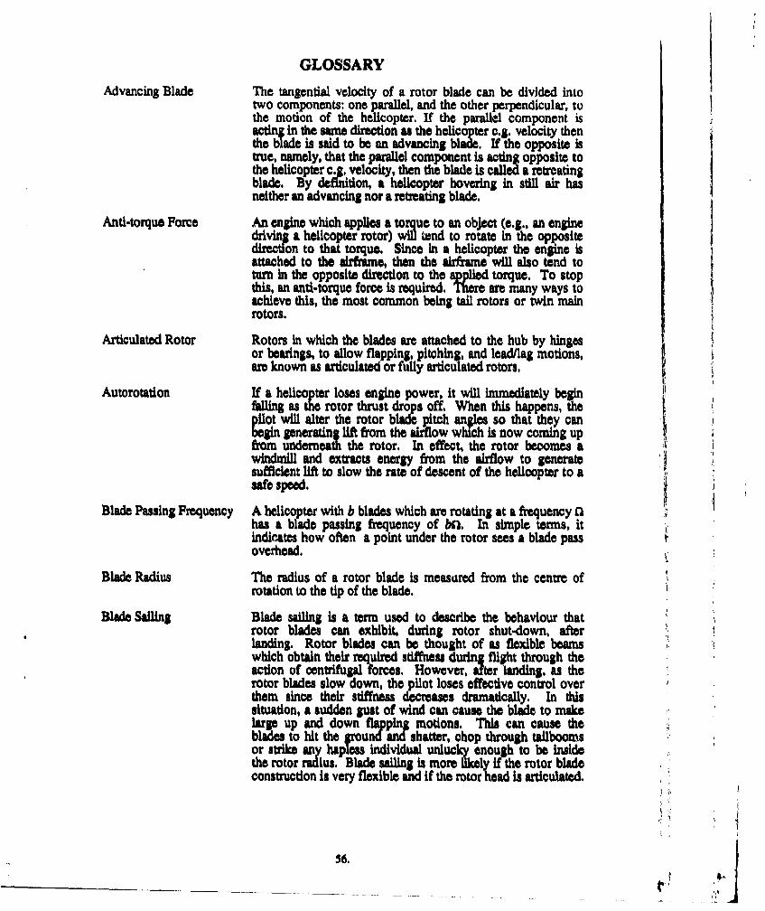
GLOSSARY
Advancing Blade The tangential velocity of a rotor blade can be divided intotwo components: one parallel, and the other perpendicular, tothe motion of the helicopter. If the parallel component isacting in the same direction as the helicopter c.g. velocity thenthe blade is said to be an advancing blade. If the opposite istrue, namely, that the parallel component is acting opposite tothe helicopter c.g. velocity, then the blade is called a retreatingblade. By definion, a helicopter hovering in still air hasneither an advancing nor a retreating blade.
Anti-torque Force An engine which applies a to ue to an object (e.g., an enginedriving a helicopter rotor) 2 tend to rotate in the oppositedirection to that torque. Since in a helicopter the engine isattached to the airfirame, then the airframe will also tend toturn in the opposite direction to the applied torque. To stopthis, in anti-torque force is required. There are many ways toachieve this, the most common being tail rotors or twin mainrotors.
Articulated Rotor Rotors in which the blades are attached to the hub by hingesor bearings, to allow flapping, pitching, and lead/lag motions,are known as articulated or fuilly articulated rotors.
Autorotation If a helicopter loses engine power, it will immediately beginfnas the rotor thrust drops off. When this happens, thepilot will alter the rotor blade pitch angles so that they canbegin generating lift from the aidflow which is now coming upfro: underneath the rotor. In effect, the rotor becomes awindmll and extracts energy from the airflow to generatesufficient lift to slow the rate of descent of the helicopter to aWO speed.
Blade Passing Frequency A helicopter with b blades which are rotating at a frequency Q 1has a blade passing frequency of btl. In simple terms, itindicates how often a point under the rotor sees a blade passoverhead.
Blade Radius The radius of a rotor blade is measured from the centre ofrotation to the tip of the blade.
Blade Sailing Blade sailing is a term used to describe the behaviour thatrotor blades can exhibit, during rotor shut-down, afterlanding. Rotor blades can be thought of as flexible beamswhich obtain their required stiffness during flight through theaction of centrifugal forces. However, after landing, as therotor blades slow down, the pilot loses effective control overthem since their stiffness decreases dramatically. In thissituation, a sudden gust of wind can cause the blade to makelarge up and down flapin motions. This can cause theblades to hit the groundand shatter, chop through tailboomsor strike any hapless individual unlucky enough to be insidethe rotor radius. Blade sailing is more likely If the rotor bladeconstruction Is very flexible and if the rotor head is articulated.
56. *_ _ _ _
Chordwise Refers to a direction or force which is in the plane of motionof a particular rotor blade. Bending moments which causebending in the chordwise direction are referred to aschordwise (or chord) bending moments. See also: Flapwise
Coaxial rotors A helicopter with coaxial rotors has two main rotors mountedone on top of the other. They are made to rotate in oppositedirections, thus cancelling the torque effects of the engine onthe airframe. See also: Anti-torque Force
Collective The collective refers to the components in the rotor systemthat control the amount of constant pitch angle applied to therotor blades. When the collective stick is moved, the pitch ofall the blades changes by the same (i.e. by a collective)amount. The collective controls the amount of thrustproduced by the rotor. See also: 5wash Plate
Collective Stick The cockpit control stick that controls the amount ofcollective pitch.
Cyclic The term "cyclic" refers to the components in the rotor systemthat control the range of pitch anges through which a blademoves as it rotates through 360 about its rotor shaft. Ahelicopter without cyclic controls would roll over because itsadvancing blades iwould generate more lift than its retreatingblades. With cyclic controls, the blade angles can be varied sothat the lift produced by all the blades is balanced. The cycliccontrols also determine the direction of motion of thehelicopter by tilting the rotor thrust vector in the appropriatedirection. See also: Advancing Blade, Swash Plate
Cyclic Control Stick The cockpit control stick that controls the amount of cyclicpitch. It is analogous in its function to the control stick in afixed-wing aircraft.
Drag Damper Another term for Lead/Lag Damper
Disc Loading The ratio obtained by dividing the weight of a helicopter bythe rotor disc area.
Drag Hinge Another term for Lead/Lag Hinge
Dragwise Another term for Chordwise
Edgewise Another term for Chordwise
Flapping The blades on a rotating helicopter rotor do not remain in afixed plane perpendicular to the rotor shaft. Instead, theblades move up and down as they rotate in order to keep thelift, inertial and gravitational forces in equilibrium. Thismotion is called flapping.
Flapwise Refers to a dirmcon or force which is perpendicular to theplane of motion of a particular rotor blade. Bending momentswhich caus bending in the Flapwise direction are referred toas flapwise or flap bending moments. See also: Chordwise 4
Flatwise Another term for Flapwise
57.
Ground Resonance A cpndition in which the motion of the centre of gravity (c.g)of a rotor couples with the sideways or fore and aft motion ofthe rotor shaft. If insufficient damping is present, thehelicopter will rock from side to side, out of phase with themovement of the rotor c.g. The condition mainly occurs onthe ground since then the helicopter is resting on itsundercarriage, which provides only light damping againstrocking motions. If ground resonance begins, it can cause the
disintegration of a helicopter within seconds. See also:Lead/oag Damper
Ground-Air-Ground Cycle The Ground-Air-Ground (GAG) cycle consists of the largevariation in load which occurs once per flight. The minimumload for a GAG load cycle is either zero or the largestnegative load seen by the rotor system on the ground orduring the flight. The maximum load is the highest positiveload experienced by the rotor system during the flight, be it aflight load or a landing load.
Hinged Rotor Another term for Articulated Rotor
Hingeless Rotor Another term for Rigid Rotor
Hub The rotor hub is at the centre of the rotor system. Itcomprises the blade control system (linkages, swash plate etc)and it transmits engine torque to rotate the blades as well asreacting the resulting blade loads.
Jump Take-off If a helicopter takes off vertically from its landing pad withoutground taxiing first, it is said to be using a jump take-off.
Lagging When a helicopter is hovering in still air, the blades that makeup its rotor, when viewed from above, are equally spaced.However, when the helicopter begins to move horizontally inany direction, the blades are no longer equally spaced. Whencompared to their positions in hover, some of the blades willbe lagging behind where they were in the hover while otherswill be ahead (i.e. leading). This leading or lagging motionoccurs in a chordwise sense.
Lag Hinge Another term for Lead/Lag Hinge
Leading See Lagging
Lead/Lag Damper This is the damper which is installed in rotor heads to preventgrund resonance from occurring. It achieves this by damping
lead/lag motion of the rotor blades.
Lead/LAg Hinge The hinge mounted at the root of a rotor blade which allowsthe blade to lead or lag.
Lift Frames These are the frames in a helicopter which provide the loadpath for the main rotor thrust to lift the weight of the airftameand payload.
58,
Nap-of-the-Earth Flight Helicopters are more vulnerable to anti-aircraft defences thanfixed-wing aircraft. To combat this, military helicopter pilotsfly in what is termed NOE (Nap-of-the-Earth) flight. Thisconsists of the ielicopter flying at high speed at or below tree-top height and following the contours of the ground.
Rigid Rotor A rotor in which the blades are rigidly connected to the huband the hub is rigidly connected to the rotor shaft is known asa rigid rotor. That is, unlike an articulated rotor, the bladeflapping, pitching, and lead/lag motions are notaccommodated by hinges or bearings. Instead, the blademotions are catered for by beams which have stiffnessesstailored to allow the various motions.
Root Cut-out The rotor blade does not physically start from the centre ofrotation. There are several reasons for this: the purelyphysical problem of several rotor blades attempting to occupythe same point in space is one, while another is the desire toreduce the size of the stalled flow region near the hub. Hence,the term "root cut-out" refers to the distance from the centreof rotation to where the blade physically begins.
Rotor Engagement When a helicopter starts its engine, the rotor is disconnectedfrom the drivetrain until the engine reaches its operatingcondition. At that time, the drivetrain is connected to therotor to begin driving it. This is called rotor engagement.
Retreating Blade See Advancing Blade
Rotor Disc Area If R is the blade radius then the rotor disc area is defined as7,R2.
Rotor Shaft The shaft which transmits engine torque from the engine tothe hub.
Run-on Landing A run-on landing occurs when a helicopter lands with someforward velocity.
See-saw Rotor Another term for Teetering Rotor
Semi-articulated Rotor A semi-articulated rotor has some of the characteristics of anarticulated rotor and some of the characteristics of a rigidrotor. That is, pitching and lead/lag motions may beaccommodated b hinges while flapping may beaccommodated by the deflection of a beam.
Sideflare A sideflare is a the same as a normal landing flare except thatit occurs in a sideways direction.
Swash Plate The swash plate is a key component in the rotor system. Itconverts control system commands from a non-rotatingsystem (the pilot controls) to a rotating system (the rotor).
Tail Rotor A tall rotor is a small rotor mounted at the rear of a helicopterwhich runs at five to ten times the speed of the main rotor. Itsmain function is to provide the required anti-torque force byenerating a counter-acting side thrust. See also: Anti-torque
Force
Tandem Rotors A tandem rotor helicopter has two main rotors turning inopposite directions in the same way as a helicopter withcoaxial rotors and for the same reason. The difference is thatthe rotors are not mounted coaxially, but, instead, one issituated at the front of the helicopter and the other at the rear(i.e. a tandem arrangement).
Teetering Rotor A rotor In which the blades are rigidly connected to the hub,but the hub is fiee to tilt with respect to the rotor shaft, isknown as a teetering rotor. It has been widely used on Bellhelicopters.
'0
60. " '"iq .2
DISTRMUTION
AUSTRALIA
1ý_Rartent gf adaefe
Chief Defence ScientistAS, Science Corporate Management shared copyFAS Science PolicyDirector, Departmental PublicationsCounsellor, Defence Science, London (Doc Data sheet only)Counsellor, Defence Science, Washington (Doc Data sheet only)Scientific Adviser, Defenc& CentralOIC TRS, Defence Central LibraryDocument Exchange Centre, DSTIC (8 copies)Defence Intelligence OrganisationLibrarian, Defence Signals Directorate, (Doc Data sheet only)S.A. to Thailand MED (Doc Data sheet only)S.A. to the DRC (Kuala Lumpur) (Doc Data sheet only)Director General - Army Development (NSO) (4 copies)Industry Policy and Programs Branch, FAS
Aeronautical Research LaboraorDirectorLibrary
Chief Airframes and Engines DivisionAuthor: D.C. Lombardo
CX. Rider0.S. JostJ.M. GrandageJ.G. SparrowP.A. FarrellK.F. FraserN.S. Swanason3. FaragherR.C. AdamsC.N. King (Contractor Propulsion)L. MirabellaN. E. Gilbert
LrialRerchLabmtnDirector/Library
Defence Science & Technolong Organitnation - SalnburyLibrary
Navy Scientific AdviserAircraft Maintenance and Flight Trials UnitRAN Tactical School, Library
______________ _____________ ______r___i'",
Director Aircraft Engineering - NavyDirector of Naval Air WarfareNaval Support Command
Superintendent, Naval Aircraft LogisticsDirectorate of Aviation Projects - Navy
Scientific Adviser - ArmyDirector General Land Warfare AgencyController Maintenance Engineering Agency, Attn. Maj EldonJohn Considine, Staff Officer (Science), HQ 1 st DivisionEngineering Development Establishment LibraryUS Army Research, Development and Standardisation Group (3 copies)
Air Force Scientific AdviserAircraft Research and Development Unit
Scientific Flight GroupLibrary
DENGPP- AFDGELS (A•REG4)Director Helicopter Projects - APDirector Air Force SafetyOIC ATF, ATS, RAAFSTT, WAGGA (2 copies)
Director General Force Development (Air), AQn: DD-RWDirector General Force Development (Sea), Attn: DDAWD
Stautu'y and Swta Authorities and InduatryCivil Aviation Authority
C. TorkingtonAJ. Emmerson
Hawker de Havilland Aust Pty Ltd, Victoria, LibraryHawker de Havilland Aust Pty Ltd, Bankstown, Library
Universities and CnlleesAdelaide
Barr Smith LibraryProfessor Mechanical Engineering
FlindersLibrary
LaTrobeLibrary
MelbourneEngineering Library

MonashHargrave Library
NewcastleLibraryProfessor R. Telfer, Institute of Aviation
New EnglandLibrary
SydneyEngineering Library
NSWPhysical Sciences LibraryHead, Mechanical EngineeringLibrary, Australian Defence Force Academy
QueenslandLibrary
TasmaniaEngineering Library
Western AustraliaLibraryHead, Mechanical Engineering
RMITLibraryMr M.L. Scott, Aerospace Engineering
University College of the Northern TerritoryLibrary
CANADANational Defence Headquarters
Paul Arnell DAS-ENG 6-3-2
UNITED KINGDOMDefence Research Agency
Dorothy M. Holford
Civil Aviation AuthoritySteven L. James
Weutlands Helicopters LimitedJohn Duthie
Royal Air ForceSqn Ldr Andy Leahy ADSM (Air Eng) 17c
UNITED STATES OF AMERICAUS Army Vehicle Structures Directorate
NASA Langley Research CenterWolf ElberFelton BartlettRichard Eve.,tt
ITS Army Aviation Applied Technology DirectorateDan Good
US Army Aviation and Troop CommandFrederick H. ImmenRobert W. ArdenRandy L. BucknerKevin M. Rotenberger
US Navy Naval Air Systems CommandGene BarndtMargery HoffmanRay SacareiliRose Zamit
US Air Force Warner Robbins APBGary Chamberlain WR-ALC/TIBDD
McDonnell Douglas Helicopter CompanyMostafa Toosi
Bell Helicopter TextronJim Cronkhite
Sikorsky AircraftJames L. Harrell
Kamnan Aerospace CorporationClifford T. Gunsallus
SPARES ( 10 COPIES)
TOTAL (118 COPIES)
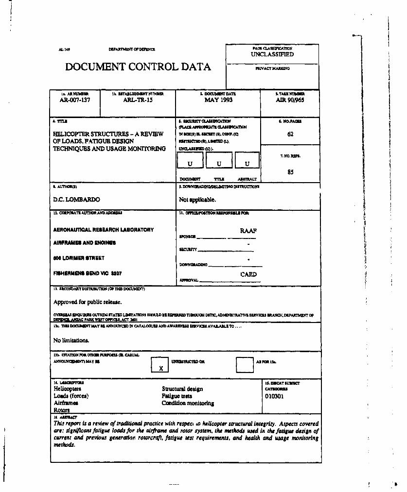
AL 149 DUMKAThMt OF EIW PACK LASSUWIATION
UNCLASSIFIEDDOCUMENT CONTROL DATA PRIVAC______
IL. ARUMMH3 1 3,ABLIOuMPRYMtS 2. DOCU&W= ,AT S. TASK MIReAR-007-137 ARL-TR-15 MAY 1993 AIR 90/965
.rTLA L, hU EYCASSIPICAUMI C NO.PAnl
4CS, LNVANI IATS hASuICeA1ON
HELICOPTER STRUCTURES - A REVIEW N W) SUM (.c8).ccO 62OF LOADS, FATIGUE DESIGN mCrM LLWm 04,TEC MNIQUES AND USAGE MONITORING uxM.Aurmw , IN0.1.PS.
85
DOCUMENT rMTL AunsAcr
SAtI7HO•S) 0. O•WNGRADIGILDMNO INsTRU•TIONS
D.C. LOMBARDO Not applicable.
10, COUPORAPSAUTHOS AIDADI*SS 11. OMPILMMSON RESPONSIBL PO~
AERONAUTICAL RESEARCH LABORATORY RAMSPONSOR_,
AIRPRAMES AND ENGINEIS
O0N LORIMER SiTEEr
FISHERMENS BEND VIC 3207 CAEDAPPOVAL ____ __
IL. SECONDARY DISThZWIUON (OF n0S 1DOCLI3(r)
Approved for public release.
OVESEAS EIQU2BS W S1DI STAMM LUWAITAONS SHOULDB RIIRRD rn.WTRIJN DSICE, AlMDhENTRATIB SERVICES 3LANCK4 DEPARMAKI(T OPN PARu wIFrrOMPS, A•T 301
13L. THI DOCU•ETr MAY IS ANNOUNCED IN CATALO•IUS AND AWARIEUSS SRVIK AVALAIL TO ....
No limitations.
0b. CITATION^ •POTHERURPOSS (3.CASUALAnoNNoUmenf MAY 35 [jUNRISSTUCTIVOIL[ AS POP. 1U.
wt wapr• 1$.DVICAT IUNICHelicopter Strgucuda design CA710M
Lod (forces) Fatigueoots 010301Airframes Condition monitoringRotors
This report is a review of traditional practice with respec, to helicopter structural integrity. Aspects coveredare: signilcant fatigue loads for the airframe and rotor system, the methods used in the fatigue design qfcurrent and previous generatior roworcrft, fatigue test requirements, and health and usage monitoringmethods.
UNCLASSIWMD
PMIACY HAIW(O
ThIS PAM IS TOUR1 USM TO RC W DMRW11ON WUidQ 3 XWWU BY THS WAXAIISGMW P=a m OWN~ WB 3UffWý=O WC. NOT W AD=I TO MOWfll DATA WASSZ SPSCALLY RBQUUSTI.
It. ASMTACT(CONn)
17. ODft $
AERONAUTICAL RESEARCH LABORATORY, MELBOURNE
1S, DO003N SUM3 ANIDN1U~R to, WA'mm XIhU , TYMCI0FMW~IIVPWROCOVSUID
Tcchrdea1Report 15 24 213F
U1. TSR MMOORA~dS13*5
3L ASTAKLISISNTILI 46)
33. ADOMONAL 24RtRUATM0 (AS PSQUUW)


![‘CP’ and Department of Defence [2014] AICmr 88 (2 ... · 1 ‘CP’ and Department of Defence ... 3 (Plain English Guidelines) ... ‘CP’ and Department of Defence [2014] AICmr](https://static.fdocuments.net/doc/165x107/5b46e7987f8b9a5e5f8bcdd7/cp-and-department-of-defence-2014-aicmr-88-2-1-cp-and-department.jpg)
