DEPARTMENT OF ELECTRICAL ENGINEERING …mathewjohn316.angelfire.com/report.pdf · department of...
82
DEPARTMENT OF ELECTRICAL ENGINEERING SENIOR DESIGN ENGINEERING REPORT GPS AUTONOMOUS DRIVE BY WIRE GO-KART PROJECT ADVISOR: DR. RUSSELL CLARK GROUP MEMBERS: JOSH HICKS, MATHEW JOHN, AJAYPAL KAHLON & PRATIK PATEL DATE: APRIL 27 TH , 2007
Transcript of DEPARTMENT OF ELECTRICAL ENGINEERING …mathewjohn316.angelfire.com/report.pdf · department of...

DEPARTMENT OF ELECTRICAL ENGINEERING
SENIOR DESIGN ENGINEERING REPORT
GPS AUTONOMOUS DRIVE BY WIRE GO-KART
PROJECT ADVISOR DR RUSSELL CLARK GROUP MEMBERS JOSH HICKS MATHEW JOHN AJAYPAL KAHLON
amp PRATIK PATEL
DATE APRIL 27TH 2007
Table of Contents
1 Introduction 11 Abstract 1 12 Drive-By-Wire Technology 1 13 The Global Positioning System (GPS) 2 14 Project Objectives and Advantages 6 15 System Overview 8
2 National Instruments Data Acquisition Boards
21 The Need for Data Conversion 10 22 The NI 6008 amp 6215 10
3 Steering System
31 Steering System Overview 13 32 Roboteq AX2550 Controller 13 33 Position Feedback Potentiometer 15 34 Steering Safety System 16 35 Pulse Width Modulation (PWM) 17 36 NI DAQ 6008 18
4 Drive and Brake Systems
41 Drive and Brake System Overviews 19 42 Drive and Brake Interfacing with DAQ 19 43 NI DAQ 6215 20
5 GPS System
51 GPS Receiver amp Operation 22 512 GPS Implementation 23 513 Trimble Receiver Specifications and Omni-star Correction Service 23 52 Understanding GPS Coordinates 24 53 Coordinate form 25
54 The GPS Receiver String 25 55 The Parser Function 27 56 Vector Calculus 27 561 Adding Vectors 29 562 The Dot Product 29 57 How The Go-Kart Drives By Itself 30
6 Ultrasonic Sensors 61 Ultrasonic Sensor Background 32 62 VM125 Ultrasonic Radar Sensors 32 63 Sensor Operation 33 64 Sensor Housing 35
ii
7 Tachometer
71 Tachometer Feedback 37 72 Hall Effect Speed Sensor 37 73 The Tachometer Subsystem 39
8 Computer 40
9 TransmitterReceiver 91 TransmitterReceiver Module 41 92 Power Relays 41
10 Emergency Stop
101 Safety Concern 44 102 Emergency Stop Implementation 44
11 Brake Light
111 Brake Light Purpose amp Specifications 47 112 Comparator Circuit 47
12 Detailed System Overview
121 Entire GPS Autonomous DBW System 49 122 Final System Overview 49
13 Troubleshooting Problems amp Discarded Designs 51
14 Schedule amp Finance
141 Timeline 53 142 Cost Analysis 54
15 Conclusions 55
16 Appendices
Appendix A ndash Steering System Code 57 Appendix B ndash Drive + Brake System Code 59 Appendix C ndash GPS Parse amp Database Map Points C++ Code 64 Appendix D ndash Collision Avoidance Sensor Code 70 Appendix E ndash Speed Feedback Sensor Code 73 Appendix F ndash Brake Light Code 75
17 References 77
iii
Acknowledgements
bull Dr Russell Clark
o Project Advisor
o Provided insight into entire system design
bull Michael Gubody amp Mark White
o Members of the SVSU ACM Club
o Graciously provided programming amp debugging tips and help
bull Mike Houghtaling (PNC Ag Solutions) amp Omni-star
o Provided the Trimble GPS Receiver on loan
o Omni-star provided free Educational trial Signal Correction Service (VBS)
bull Pietro Condello amp Mike Nedescu (DBW Group - lsquo05rsquo06)
o Helped with the familiarization of their project configuration
o Provided intricate details that werenrsquot included in their report
o Mechanical help
bull The rest of the SVSU Electrical Engineering Faculty
o Fielding any random questions over the projectrsquos duration
o Giving tips or advice whenever asked
iv
Part 1 Introduction
11 ndash Abstract
The goal of this project is to design an autonomous Drive-By-Wire Go-Kart
system The Go-Kart will be able to navigate itself using a computer interfaced with a
GPS receiver which will provide position and navigation referencing The computer will
also interpret the Go-Kartrsquos surroundings and avoid collisions with foreign objects with
the use of collision avoidance sensors A speed sensor will measure how fast the Go-
Kart drives by delivering speed data to the computer The laptop will adjust the Go-
Kartrsquos speed accordingly depending on the Drive Brake and Steer system
requirements This project hopes to introduce the notion of conventional autonomous
driving to faculty staff students and observers with aims to influence inspire and build
continual interest in the field of autonomous control as its implemented use in a not so
distant future
12 ndash Drive-By Wire Technology
Cars are complex devices that carry out a fairly simple function The Steering
system in a car works to turn the wheels from side to side while the Drive and Brake
systems control the speed of the wheels In essence the overall operation of a car is to
provide rotary motion to its wheels Todayrsquos cars contain a large amount of complex
mechanical devices and hydraulic linkages When it comes down to the function of the
car does the car really need such components such as a steering column brakes and
acceleration pedals combustion engine and a catalytic converter This question
1
attempts to expose Drive-by-Wire as an alternative approach to conventional
automotive design
Drive-By-Wire is a technology that attempts to implement the basic functions of a
car without the assistance of complex linkages and mechanical support systems The
concept of this environmentally friendly technology itself is quite simple and does not
require the presence of a catalytic converter or any emission cleaning device The
Drive-By-Wire System is electrically powered using a battery or fuel cell that powers an
electric motor connected to the wheels Instead of using the mechanical linkages to
maneuver the vehiclersquos actuators a computer operates the actuator systems directly
such as the wheels drive motor and brakes These actuators are controlled based on
an input to an electronic controller which comes from the driver or in an autonomous
Drive-By-Wire system such as the one designed for this project the input may be pre-
programmed from a computer itself
13 ndash The Global Positioning System (GPS)
One of the main components of this project is the Global Positioning System
(GPS) It was developed in the United States by the Department of Defense (DoD) in
the early 1970rsquos and was initially intended for military needs Later GPS was made
available to civilians and is now a dual-use system that can be accessed by both
military and civilian users around the globe GPS consists of a constellation of 27
satellites 24 of which are working and three that are set as standby in case one of the
24 satellites fails In either case the system relies on the function of 24 satellites that
are grouped in fours having each group placed in six separate orbital planes that orbit
2
the earth Each satellite is solar powered weighing 3000-4000 lbs traveling at speeds
up to 12000 mileshr (19300 kmhr) and completing two complete rotations of the Earth
every day With this specific GPS constellation geometry four out of ten satellites will be
visible at any point on the earth Only four satellites are needed to provide positioning
and location information
Figure 1 The GPS Constellation
GPS consists of three segments of operation The first being the space segment
(described above) the second is the control segment and the third and final segment is
known as the user segment Each GPS satellite transmits a signal consisting of two
sinusoidal carrier frequencies two digital codes and a navigation message The digital
codes and navigation message are added to the carriers later once the signal has been
modulated to a GPS receiver Together the carriers and the codes are used to
determine the distance from the userrsquos receiver to the GPS Those three segments
described can be seen in Figure 2 below
3
Figure 2 The Three GPS segments
The control segment of the GPS system consists of a worldwide network of
tracking stations with the master control station (MCS) located in Colorado Springs
Colorado This station evaluates the validity of the satellites by examining their current
location on the orbits system integrity satellite atomic clocks behavior atmospheric
data the satellite almanac and other maintenance considerations Other workstations
provide differential global positioning system service with an accurate correction signal
This is needed because the Earths atmosphere slows the electromagnetic energy as
the signal goes through the ionosphere and troposphere A delay is generated and
varies depending on global location on Earth making it difficult to accurately compute
distance calculations Problems can also occur when GPS radio signals bounce off
large objects such as buildings giving the receiver the impression that a satellite is
farther away than it actually is On top of all that satellites sometimes just send out bad
almanac data misreporting their own position Differential-correction stations help
4
correct these errors The basic idea is to measure GPS inaccuracy at a receiver station
with a known location Since the Differential GPS (DGPS) hardware at this station
already knows its own position it can easily calculate the receivers inaccuracy The
station then broadcasts a radio signal to all DGPS-equipped receivers in the area
providing the necessary signal correction information In general access to this
correction information makes DGPS receivers much more accurate than ordinary
receivers Some correctional services such as Coast Guard Beacon Signals and Wide
Area Augmentation System (WAAS) are free to use without charge Other services
which guarantee precise accuracy charge a monthly or annual fee based on the
different subscriptions offered
Figure 3 Differential GPS Positioning Diagram
The final segment of GPS is known as the user segment includes all military and
civilian users with a GPS receiver connected to a GPS antenna (usually built-in) With
this device users can receive GPS signals which are used to determine position
anywhere in the world Direct GPS is currently available to all users worldwide at no
5
direct charge The most essential function of a GPS receiver is to pick up the
transmissions of at least four satellites and combine the information in those
transmissions with information in an electronic almanac in order to determine the
receivers position on Earth Using the signals from each satellite the receiver takes
each reference signal and calculates a final position relative to its location This
operation is based on a simple mathematical principle called tri-lateration which uses
three-dimensional positioning in spherical form
GPS can be implemented in a variety of sophisticated navigation applications
While providing high-accuracy positioning in a cost effective manner GPS has found its
way in to many applications such as handheld or automotive based receivers
essentially replacing such conventional tools as compasses and maps By interfacing a
GPS receiver with a microprocessor or laptop that controls the functions of a car GPS
may prove to be more efficient in eliminating all types of human error found in todayrsquos
modern driving methods
14 ndash Project Objectives and Advantages
The objective of this project is to combine two heavily researched and
demanding technologies the first being GPS navigation and the second Drive-By Wire
technology into one autonomous Drive-By-Wire Go-Kart design Besides the obvious
advantages of increasing safety and reducing road accidents which will save lives the
possibility of having vehicles moving in much closer proximity than they do today would
produce an increase in road capacity A more intelligent modulation of each vehicles
6
speed would also result in an appreciable reduction in fuel consumption In other words
autonomous vehicles have the potential to achieve optimal use of current transportation
infrastructures improve mobility minimize risks decrease travel times and reduce
energy consumption Moreover commercial and industrial vehicles which repeatedly
move along specific routes would benefit from a stronger control of their routes and
would require fewer personnel to manage their moves This project shows how a
possible low-cost environmental friendly solution can successfully adapt to drive an
ldquointelligentrdquo vehicle in real-world conditions The Drive-By-Wire platform will react
quicker and more responsive than the todayrsquos mechanical linkage equivalents The
mechanical linkages that vehicles today use to actuate motion requires energy transfer
by coupling or linking one device to another to achieve its purpose Using the Drive-By-
Wire electronic signals actuators can be directly interfaced and activated by the current
that flows through a wire therefore achieving the task with fewer losses Since there is
a direct correlation between the responsiveness and performance of a vehicle using
motors in place of mechanical linkages can prove to be more efficient and perhaps be
the next transitional phase in automotive technology This technical report goes into
detail in describing the underlying architecture of this project in its entirety
7
15 ndash System Overview
The following block diagram shown below in Figure 4 gives a basic introduction
of the systems being integrated together in this project
Laptop
GPS Receiver
Collision AvoidanceSensors
SpeedSensor
DriveSystem
SteeringSystem
BrakeSystem
Figure 4 Basic Block Diagram of GPS Autonomous System
All of the systems above are included on the Go-Kart and each individual system
plays an important role to its overall function In this diagram the GPS receiver will
constantly provide the Go-Kart with its current position and therefore be able to navigate
a path by which it will travel The collision avoidance sensors will detect objects in front
and at the rear of the Go-kart to avoid collisions The Speed sensor constantly tracks
the speed of the Go-Kart This information is important to the computer because it
needs to always be aware of how fast the Go-Kart is traveling before it can carry out
any of the Drive-By-Wire functions (Drive Brake amp Steer)
8
Figure 5 A more detailed block diagram outlining signal conversions between devices
Figure 5 shows the types of data conversions made between each of the
projectrsquos subsystems as well as illustrating the types of hardware connections made
with the computer The GPS signal being sent as an input to the computer by a serial
connection sends a direct form digital data strings The Collision Avoidance sensors
send a combination of analog and digital data where the analog signals are converted
to digital signals using an analog to digital conversion and are sent as an input to the
computer via USB The Speed sensor sends digital data through an analog to digital
conversion as an input to the computer via USB as well The computer takes all of the
analog values and digitally converts this information for processing the necessary
algorithms to provide the correct output signals to the Drive Brake and Steer systems
which undergo a final conversion from digital back to analog The need of providing both
types of data conversion is imperative for the system
9
Part 2 National Instruments Data Acquisition Boards
21 ndash The Need for Data Conversion
Since a reliable system was needed between the laptop and the subsystems that
essentially make the Go-Kart function properly and efficiently The system had to be
able to send the proper signals from the computer to the Drive Brake and Steer
systems It was also essential that these signals were executed in real time to avoid
delays between the signals being sent and received by the computer An emphasis was
made on the importance of real time data conversions and a major objective in this
project was finding those devices so that all of the necessary functions could be
implemented smoothly Interfacing an operating system with external devices using the
serial port (RS-232) on a computer has been a popular method However due to the
rapid development of the Universal Serial Port (USB) the RS-232 standards are
becoming obsolete USB technology has become hundreds of times faster than the
serial port and has created more improved interfacing standards With up-to-date USB
standards it is possible to use this interfacing technology for more complex and real-
time applications in user-friendly and dependable methods
22 ndash The NI 6008 amp 6215
The National Instruments USB Data Acquisition Boards (NI USB DAQ) were the
ideal devices that would perform the necessary analog to digital and digital to analog
signal conversions which were required for the computer interface with all of the
subsystems properly The NI USB DAQ proficiently performed all the conversions in a
10
real-time consistent manner The boards provide basic DAQ functionality for
applications such as data logging sophisticated measurement applications and
conversions between analog and digital signals and vice versa in the C programming
language However real time applications are done with greater ease in C++ so all of
the systems are written in a combination of CC++ language With up-to-date drivers
and compatibility for a wide variety of operating systems such as Microsoftrsquos Windows
or Linux these devices provide convenience and portability interfacing techniques The
NI USB-6008 and NI USB-6215 were both used for this project They provided powerful
solutions to successfully implement all necessary applications needed for autonomous
control Analog voltages were needed to control the Drive Brake and Steering
controllers which were essentially the key hardware output components on the Go-Kart
A Brake light was also activated by an output analog voltage from one of the DAQrsquos
which was programmed to light up in synch with the activation of the brake and turn off
when the brake was deactivated Some of the other input devices that were interfaced
with the NI USB DAQrsquos were the Speed sensors and the Collision avoidance sensors
Table 1 summarizes and compares the key specifications of the two NI USB boards
used which are shown in Figure 6
11
Figure 6 NI USB-6008 amp 6215 Data Acquisition Boards
NI USB-6008 NI USB-6215 Bus Type USB USB Analog input of channels 8 16 Sample Rate 10 k Sampless 250 k Sampless Resolution 12 bits 16 bits Max Volt Range -10 to 10 V -10 to 10 V Range Accuracy 138 mV 269 mV On-Board Memory 512 B 4095 Samples Analog output of channels 2 2 Update Rate 150 Sampless 250 k Sampless Resolution 12 bits 16 bits Max Volt Range 0 to 5 V -10 to 10 V Range Accuracy 7mV 3512 mV Current Drive (per channel) 5mA 2mA Digital IO of channels 12 DIO 4DI 4DO Logic levels TTL TTL Current Drive (per channel) 85mA 16mA CounterTimers of counters 1 2 Resolution 32 bits 32 bits Max Source Frequency 5 MHz 80 MHz Logic level TTL TTL Pulse Generation No Yes Physical Specification Length 851 cm 169 cm Width 818 cm 94 cm Height 231 cm 31 cm IO Connector Screw Terminals Screw Terminals
Table 1 NI USB Data Acquisition Boards Specifications
12
31 Steering System
31 ndash Steering System Overview
The Steering system was designed based on Drive-By Wire technology The
steering system consists of a DC Gear Motor Roboteq controller Position feedback
potentiometer Current diodes Limit switches and a PWM circuit The NI DAQ applies
an input voltage to the PWM circuit which converts an analog voltage into a pulse width
modulated signal which fed as an input to the Roboteq controller
Figure 7 The existing closed loop steering system with the new additions
One of the first components of the steering system is Dayton DC gear motor
This motor operates at 12V DC has a 191 output gear ratio rated at 16 HP 94 rpm
and has a rated torque of 135 inch pounds at 126A
32 ndash Roboteq AX2550 Controller
Another one of the components in the Steering system is the Roboteq Dual
Channel High Power Digital Motor Controller shown in Figure 8 It is designed to control
a permanent magnet DC motor powered between 12 to 40V DC This controller was
13
used to interpret the command signal for the steering and the position feedback signals
and to translate them into a variable armature voltage which is sent to the Dayton DC
Gear Motor Figure 7 illustrates how the Roboteq controller was configured for existing
closed loop position control with the addition of the NI DAQ The output of the controller
is the armature voltage which will command the Gear Motor to turn
Figure 8 Roboteq Motor Controller
Figure 9 Roboteq Controller IO Connector Pin-out
14
There are two inputs connected to the controller in the steering system as shown
in Figure 9 One is the PWM input signal connected to Pin 3 The other input is the
analog position feedback signal from the feedback potentiometer which is connected to
pin 11 A voltage divider is used for the feedback and is supplied by pins 14 (+5V
output) and 5 (ground)
33 ndash Position Feedback Potentiometer
The next component of the Steering system is the Position feedback
potentiometer Its purpose is to create a closed loop steering system and it
accomplishes this by providing a DC voltage feedback proportional to the angular
position of the DC Gear motor to the Roboteq steering controller This technique was
used to help stabilize the system by correcting external disturbances This closed loop
was used as a safety precaution and by using this technique a specific input will always
command the proper output The feedback potentiometer used was a 20kΩ 5 Watt 10
turn precision potentiometer To physically connect the closed loop system the
potentiometer was coupled to the DC Gear Motor The gear ratio between the two
devices was set so that feedback pot would never reach its limit therefore the DC Gear
Motor would never have the chance to damage it
The feedback potentiometer was wired as a voltage divider using the +5V power
supply provided by the Roboteq controller It was wired so that it created a voltage that
is proportional to its angular position 0V at one extreme +5V at the other extreme The
wiper of the potentiometer was connected back to the controller and completes the
feedback necessary for the system to operate properly and without error
15
34 ndash Limit Switches and Power Diodes (Steering Safety System)
The next two parts of the Steering system are incorporated into the same section
because they culminate to create the Steering Safety System Since the Steering Gear
motor has the ability to create enough torque to tear the tie rods right off of the Go-Kart
a Safety system was implemented to avoid this from happening and was done using
Limit switches and Power diodes When the motor turns the wheels and reaches the
switches the plungers of the limit switches compress and the power to the motor will be
cut as shown in Figure 10
Figure 10 Steering System Safety System with the use of Limit Switches amp Power Diodes
Complimenting the safety limit switches are the Power Diodes They are high
current 40A diodes The diode in parallel with the switch allows the current to flow in the
reverse position so that the motor may be restarted and moved away from that limit Its
main limitation is that the switch and diode must be capable of handling the current that
flows through the motor Although the current flowing through the diodes is very high
16
only short periods of time are needed for the motor to move away from the limit
switches and let the system return back to normal
35 ndash Pulse Width Modulation (PWM)
The next part of the Steering system is the PWM circuit This circuit is
responsible for communicating with the Roboteq controller by sending a variable pulse
width modulated signal The circuitrsquos purpose as shown in Figure 11 is to create a
specified duty cycle where a pulse width of 10 ms is the equivalent of the doing a full
left turn 20 ms is the equivalent of a full right turn and pulse width of 15 ms is the
equivalent of having the wheels in a center position The PWM circuit shown in Figure
12 was created using a PWM IC and it uses an analog voltage signal from the NI DAQ
6008 and creates a proportional PWM signal based on what the code instructs
Figure 11 PWM Timing Diagram
17
Figure 12 PWM Circuit used for Steering Command
36 ndash NI DAQ 6008
The last component but possibly most important part of the Steering system is
the NI DAQ 6008 The NI DAQ replaces the Logitech Momo steering wheel from the
previous project and provides the necessary instructions to the rest of the Steering
system As previously mentioned the DAQ is interfaced with the computer via USB and
it will instruct the rest of the existing steering system to perform turning operations
Refer to Appendix A for the Steering System Code
18
Part 4 Drive and Brake Systems
41 ndash Drive and Brake System Overview
In order to translate the Drive-By-Wire Go-Kart to an autonomous vehicle the
Driver needed to be replaced by a smart and reliable computer program In
conventional Drive-By-Wire applied forces on the acceleration and brake pedals by the
driver sent command signals to the Drive and Brake controllers The speed of the
moving Go-Kart was directly proportional to the motorrsquos variable armature voltage and
the applied command signals from the accelerator pedal Also the speed of the Go-Kart
was inversely proportional to the electromagnetic drum brakesrsquo variable current and the
applied command signal from the brake pedal
42 ndash Drive amp Brake Interfacing with DAQ
To make the vehicle autonomous the computer would supply voltages to the
DAQrsquos which would send those voltages to the Drive and Brake controllers The block
diagrams in Figures 13 amp 14 explain the necessary modifications that were made for the
Go-Kart to drive itself
(The driver pressing the accelerator pedal is replaced with the DAQ which translates the computer program to the command signal to the AMC controller then to the Drive Motor)
Figure 13 Translating from Drive-By-Wire to Autonomous DBW (Drive)
19
(The driver pressing the brake pedal is replaced with the DAQ which translates the computer program to the command signal to the AMC controller then to the Brake)
Figure 14 Translating from Drive-By-Wire to Autonomous DBW (Brake)
The device that converted the applied signal into a variable armature voltage and
variable current were the Advanced Motion Control (AMC) controllers These powerful
controllers were designed to operate from 20 to 80 Volts DC and provides up to 60 A of
continuous current The Drive motor used in this project was a Leeson DC permanent
magnet motor The motor operates at 24V DC and provides a rated 1100 Watts 3000
rpm Rated torque supplied by this motor is 315 inch pound at 65 A The Brake used
was an Electromagnetic Drum brake which is mainly used for trailers This type of
Brake activates when it receives a variable current source
43 ndash NI DAQ 6215
Using the NI USB-6215 Data Acquisition Board the necessary command signals
were applied to the AMC controllers Two available analog output ports on the DAQ
were used to control the Go-Kartrsquos Drive system in the Forward and Reverse directions
Another analog output port on the DAQ was used to control the Go-Kartrsquos Brake
20
system Figures 14 amp 15 explain more about the Drive amp Brake Systems on the
autonomous Go-Kart Refer to Appendix B for Drive + Brake System Code
(The USB-6215 DAQ translates the computer program to the desired analog DC voltage The +- Reference pins on the controller are used to navigate the Go-Kart for forward and reverse directions respectively The inhibit pin on the AMC controller is normally high and a zero would cause it to the turn it off)
Figure 15 The New Autonomous Drive System
(The USB-6215 DAQ translates the computer program to the desired analog DC voltage The + Reference pin of the controller is connected to the DAQ and the controller converts the DAQ voltage to a variable current)
Figure 16 The New Autonomous Brake System
21
Part 5 GPS System
51 ndash GPS Receiver amp Operation
The GPS receiver is used to navigate the Go-Kart in driving through a pre-
determined route based on a selection of co-ordinate points located on the Saginaw
Valley State University courtyard A suitable GPS receiver intended for autonomous
application calls for precision and reliability from six to twelve inches The Trimble
AgGPS-132 was selected due to its high-performance reception and ability to receive
free and subscription correction signals in a single durable waterproof housing This
particular receiver is intended for agricultural users needing sub-meter accuracy for
various harvest and farming applications such as tagging soil types planters checking
for insect infestation combine yielding and chemical spraying This GPS receiver is
equipped with an Educational trial subscription from Omni-star which provides a
differential correction signal This type of DGPS (Differential GPS) requires two or more
receivers One receiver called the reference or base station located at a known point to
determine the GPS measurement errors An unlimited number of mobile GPS receivers
sometimes called rovers collect the data at unknown locations within the transmission
range of the reference station The reference station broadcasts correction values which
are applied to the Ag GPS receiverrsquos current position Errors common at both the
reference and rover receivers are corrected
22
Figure 17 The Trimble AgGPS-132 Unit
512 ndash GPS Implementation
The Trimble receiver interfaces to the computer through the serial port and is
powered by 12V DC Once the receiver is powered it sends a request to Omni Star to
receive a corrected signal While the receiver waits for an acknowledgement waypoints
for an intended path are needed to be stored into a text file in which the main program
will use to for navigational reference purposes
513 ndash Trimble Receiver Specifications and Omni-star Correction Service
The Trimble GPS receiver is integrated with dual channel differential beacon
receiver satellite differential receiver and Wide Area Augmentation System (WAAS)
Dual channel basically means that the receiver can use either one of the methods to
measure co-ordinates The differential beacon signal is supplied by the governments
differential correction radio-beacon network This signal is broadcasted primarily from
watch towers and light houses A good signal can be obtained within a fifty mile radius
from either location Although this service is more accurate than what a standard GPS
receiver can obtain the satellite differential position correction service provided by
Omni-Star is far superior The current signal that the GPS receives is from the Omni-
23
star virtual base station (VBS) Omni-star VBS signal is 95 accurate producing
coordinates within 6-12 inch range
52 ndash Understanding GPS Coordinates
The overall process of how the car maneuvers itself with the help of the global
positioning system is quite simple given that the concepts involved are understood
GPS coordinates are displayed by latitude and longitude It is similar to a 2D Cartesian
coordinate system (x amp y grid) but more angularly referenced rather than defined
individual points Degrees of latitude and longitude measure the angle between a
location and the reference line namely the equator and Greenwich England The
equator is a fairly obvious reference line as it creates a plane bisecting the globe half
way between the North Pole and the South Pole Latitude is the angle formed by a line
from the center of the earth to the equator and a line from the center of the earth to a
location Latitude is zero at the equator North (positive) 90 degrees at the North Pole
and South (negative) 90 degrees at the South Pole Saginaw County lies 43 degrees
latitude Longitude is far more difficult to determine without GPS Longitude is the angle
formed by a line from the center of the earth to the prime meridian at Greenwich
England and a line from the center of the earth to a location (A meridian is a line of
longitude running from pole to pole) Since the earth rotates 360 degrees each day it is
necessary to know the time very accurately in order to relate the location of the sun to
this angle The Royal Observatory at Greenwich London England is the reference of
the meridian Longitude which ranges from West (negative) 180 degrees to East
(positive) 180 degrees Saginaw County is approximately 83 degrees west With these
references intact within the computers mapping capabilities the Go-Kart constantly
24
calculates its new position as it moves The Go-Kart knows exactly where it is with
respect to the 2D coordinate system consisting of longitude and latitude positions and
what angle its supposed to steer at relative to the proceeding waypoints
53 ndash Coordinate Formats
The values of the longitude amp latitude coordinates are in the decimal degree
format coming from the GPS receiver The main program receives the decimal degree
format and modifies it by reading it with its hemisphere variables specified before the
both initial degree formats A text-file containing a chronological list of waypoints must
also be in the modified format This distinction can be seen in table 2 below
4330633379N8357667519W (Decimal degrees format coming from receiver) N 43 30633379 W 83 57667519 (Format of points that Go-Kart reads)
Table 2 ndash Receiver and Go-Kart Map preferences
54 ndash The GPS Receiver String The main program that drives the car uses a text file as a reference to read
stored waypoints for its intended route The program reads the waypoints from the top
coordinate in the text file to the bottom coordinate as the order of points for a route that
the car must follow The Go-Kart is able to geographically understand where it is and
where the first waypoint is in a virtual coordinate system perspective relative to its
current position Mathematically the car uses fuzzy logic or reasoning to maneuver
turns at various angles depending on where it needs to go Fuzzy logic is a more of an
approximate approach to calculations compared to traditional computing of precise
values Fuzzy logic tends to vaguely define directions angles based on the programmed
waypoints
25
The format that a GPS receiver sends coordinate information to a computer is in
the decimal degree format seen in the ldquo$GPGGArdquo string in Table 3 below which
explains each segment of the string
$GPGGA1235194807038N01131000E108095454690100 Numbered Segment String Segment NMEA Segment
1 $GPGGA essential prefix data indicator providing 3D location and accuracy
data 2 123519 123519s Real-time UTC
Time with respect to Greenwich England +5 hours ahead of Eastern
Standard Time 3 4807038 Latitude in decimal
degrees format 4 N Latitudinal Hemisphere
(either N or S) 5 01131000 Longitude in decimal
degrees 6 E Longitudinal Hemisphere
(either E or W) 7 1 Correction signal
Strength (See Table 4 for further details)
8 08 Number of visible satellites
9 09 Dilution of position 5454 Mean height above sea
level 69 Refresh time of GPS
coordinate 0100 Correction station ID Checksum bit
Table 3 ndash Breakdown of GPS receiver string
26
Correction Signal Strength Signal Source 0 Direct Satellite referencing (within 20m
accuracy) 1 GPS-Self Internal Differentiation (up to
20 feet accurate) 2 Field Station Differential Signal
(depending on differential signal provider signals can be corrected anywhere from 3m to 2 inch accuracy)
Table 4 ndash Breakdown of correction signal strengths 55 ndash The Parser Function
The computer is configured to analyze the entire string and use only parts of the
string for its navigation purposes When it receives the string the parser checks the
string to ensure that the string is in the proper format by running the checksum bit The
checksum bit verifies the consistency and validity of the incoming string ensuring all
segments of the string are not erroneous Once the string is verified it checks the bit of
the signal strength to ensure that the current signal is at a strength level of 2 indicating
that the Omni star service is providing an accurate signal If the bit is not a 2 the main
program that drives the car will not run until a good connection is established Once the
string indicates that the signal is corrected the next layer of the parser checks the string
for what particular parts of the string the program needs which are just the longitude
and latitude coordinates and their corresponding hemispheres (N E S amp W)
56 ndash Vector Calculus The Go-kart utilizes a lot of mathematical calculations involving 2-D vector calculus in
order to maneuver itself A vector is a mathematical object with both magnitude (length)
and direction A vector can be represented geometrically by a directed line segment
which is a line with an arrow at one end indicating the intended direction The end of
27
the line segment is called the tail or initial point and the end with the arrow is called its
tip or terminal point See Figure 18 below
Figure 18 Basic Representation of a vector
Although the vector covers a series of points it is primarily formed by two points one
being the initial point and the other being the terminal point The two points are defined
in this case in the two dimensional coordinate system In Figure 19 below vector A is
formed from initial point or tail at (-3 1) to the tip located at the origin (00) also known
as its terminal point The tail of vector B starts off at the origin (00) and ends at (23)
Finally C starts at (-15 -25) and ends at the origin (00)
Figure 19 Vectors in a sample 2-D Coordinate Plane
28
561 ndash Adding Vectors When it comes to adding vectors a technique that can be visually explained reinforces a
resultant from the sum of two vectors In other words a third vector is produced from
the vector addition of two vectors This is clearly understood by the Triangle Law of
Vector addition for vectors uand v the sum (or resultant) of uand v is a vector from the
tail of u to the tip of v When the tail of v is placed at the tip ofu Notation the sum of u
and v are denoted by vu + Refer to the Figure 20 below
Figure 20 Vectors in a sample 2-D Coordinate Plane
562 ndash The Dot Product Another useful quantity is the product of two vectors known as the dot product For
example in the 2-D coordinate system vector A = (Ax Ay) and B= (Bx By) The dot
product of A and B is the number AB This calculation produces a number that is scalar
rather than being another vector The following formula not only defines the dot product
but if θ is the angle between A and B then
ϑcos|||| BABA =bull
In simplifying the above equation the following formula finds the angle between two
vectors
||||cos
BABA bull
=ϑ
29
57 ndash How the Go-Kart Drives by itself In figure ltgt below explains how the Go-Kart drives by itself Initially the car starts off at
a position It receives the coordinates of its current position and creates a vector from its
initial point to its waypoint which is denoted as vector duv
Vector duv
is essentially the
desired direction and distance needed to reach the waypoint To travel according to this
vector a few mathematical processes have to take place in order to steer the wheels in
the right direction The car recognizes the next two waypoints and calculates a vector wuv
from the first waypoint to the second waypoint Once this vector is calculated the car
will begin to drive and analyze its change in coordinates with respect to a velocity vector
The velocity vector is incrementally calculated based on the Go-Kartrsquos constant
travel Using the dot product θv is the angle that is calculated between the velocity
vector and the true north vector This angle gives the car an idea of how much it is
turned with respect to the North vector reference The car still needs to calculate the
angle between its velocity vector to its direction vector The dot product of the two
vectors is then calculated This forms a correction angle that informs the computer of
how far it is off from reaching the desired waypoint from where it is currently located As
the velocity vector incrementally changes the car calculates the amount of voltage
required to turn the wheels so that the angle from its current position to the waypoint
can be achieved As the car approaches the waypoint or ldquotiprdquo of the vector it will begin to
correct its position until it reaches the waypoint Once the waypoint is reached the
process repeats itself making the last known waypoint the initial vehicle position
vv
30
Figure 21 Vectors in a sample 2-D Coordinate Plane
Refer to Appendix C for GPS Parse amp Database Map Points C++ code The co-
ordinates stored in the navigation database corresponding to the pre-determined route
were found by testing
31
Part 6 Ultrasonic Sensors
61 ndash Ultrasonic Sensor Background
Ultrasonic radar sensors are designed to continuously transmit and receive
ultrasonic sound waves This is done with the use of transducers which emit a sound
wave at 40 kHz exceeding the hearing range of a human The sound wave emitted
bounces off an object within a given range and returns to the transducer The Ultrasonic
echo measures the distance between the transmitted wave and the received echo
wave Some Ultrasonic Sensors also have the ability to send proportional analog
voltages to an output from the sensor corresponding to the distance calculated from
object via the ultrasonic wave This was the case for the sensor that was used in the
project
62 ndash VM-125 Ultrasonic Radar Sensors
The Velleman VM-125 Ultrasonic radar sensor was used for the collision
avoidance system for the Go-Kart There are two sensors one mounted at the front of
the Go-Kart and the other at the rear This particular sensor is more commonly used as
a parking aid sensor This sensor is extremely affective and designed for outdoor use
The ultrasonic wave emitted will reflect off an object within 8ft of the Go-Kartrsquos path back
to the transducer This echo wave was essential in calculating the distance between the
Go-Kart and the object ahead (or behind for rear sensor) The distance was then
translated to a corresponding output voltage signal A digital voltage trigger is also
integrated on the sensor whose range can be adjusted from zero to the maximum
sensing range by a 10kΩ potentiometer seen in Figure 20 For this project application
32
the range of the digital trigger was set to 5ft This trigger will send a logic ldquo1rdquo (5V pulse)
output once an object is within 5ft or less of the Go-Kartrsquos path Table 5 outlines
specifications of the Ultrasonic sensors
Range 066 to 820 ft
Frequency 40 kHz
Digital output 5V (50mA max)
Analog output 0 to 5V (5mA max)
Power supply 12V DC
Current consumption 200mA max
Dimensions 43rdquox20rdquox07rdquo
Table 5 VM125 Ultrasonic Radar Sensor specifications
Figure 22 The Ultrasonic Radar Sensor-VM125
63 ndash Sensor Operation
Since the sensor was equipped with both analog and digital outputs they were
both used The digital trigger is directly connected into an input port of the 6215 DAQ
board and will act as an interrupt in the sensing code Once the digital pulse is received
33
by the DAQ the computer program will pause and stop the Drive and Steer systems
while applying the Brakes At this point the sensor will continually send out sound waves
until a reflected response is no longer received thus indicating the object has been
removed and the path is cleared
The analog voltage that is proportional to the distance between the Go-Kart and
the object is also connected to the 6215 DAQ board It is a separate connection from
the digital trigger supplying the DAQ with the proportional voltage level concerning the
distance of an object in the Go-Kartrsquos path An object detected at 8ft (the maximum
sensing distance of the sensor) would generate a voltage of 45 V at the output Any
objects detected closer to the sensor will result in a lower output voltage This is how
the distance to voltage translation is set A more detailed distance to voltage
proportionality is shown below in Table 6 See Appendix D for the Collision Avoidance
Sensor Code
Distance (ft) Voltage (V)
50 29-35V
40 18-20V
30 13-14V
20 08-09V
10 030-042V
Table 6 The sensors distance as a proportional analog voltage
34
Figure 23 The wiring schematic for the VM125 Sensor Module
There are four LEDS on the sensors as shown in Figure 23 Three of the LEDS
flash when an object is within the sensors range of 0-8ft indicating that the analog
voltage is varying with respect to the objectrsquos distance The fourth LED is independent
of the other because it notifies users when the digital trigger is set meaning that the
object lies within 5ft of the Go-Kart This is the point where the threshold voltage limit
was set in the sensor code So when an object is within 5ft voltages lower than 3V will
tell the Go-Kart to stop A buzzer can also be wired to the sensor as a warning
mechanism using the relay included on the sensor providing an auditory warning when
objects are within its range
64 ndash Sensor Housing
The sensors are housed and mounted in plastic project boxes to provide
protection from any damage that may occur when the Go-Kart is in motion The sensors
are connected in parallel with each other and are powered by a single 12V 9AH DC
battery which is sufficient in providing adequate current to each sensor
35
Figure 24 The front sensor inside the protective housing
36
Part 7 Tachometer
71 ndash Tachometer Feedback
The calculation of the Go-Kartrsquos speed was necessary for the computer to know
how fast it was traveling The Go-Kart can only maneuver itself along with its
subsystems under certain speeds The speed was also affected by the friction of the
driving surface and the weight to load ratio of the Go-Kart Without a Tachometer it
would be impossible to carry out the overall Autonomous Drive function of the Go-Kart
The tachometer system required a successful and accurate speed measurement of the
moving Go-Kart which will be computed by taking the measurements into the main
program A tachometer circuit is more commonly known as a feedback circuit that would
assist the Go-Kart for accurate speed updates at necessary times The Tachometer
feedback connection is shown in Figure 25 using a previous Drive system block
diagram
Drive Controller Drive Motor Rear Rotating
Axel
Tachometer
rpmvoltsIP from Laptop
DAQ
Figure 25 The Drive system using the tachometer feedback
72 ndash Hall Effect Speed Sensor
The Tachometer system established for this project uses a Magnetic Hall Effect
sensor The Hall Effect speed sensor is a transducer which sends an output response
37
when a change occurs in the magnetic field density Most applications involving
proximity switching positioning speed detection and current sensing all use a Hall
Effect sensor within their systems The magnetic field detection sensor used in this
project was a Cherry Corporation magnetic proximity sensor This sensor has
exceptional capabilities and was well suited for this project The sensor gives out a
digital output and can be easily mounting to any surface as shown in Figure 26 The
transducer itself is contained in a waterproof housing Table 7 contains the
specifications of the sensor
Operating Voltage 475V to 12V
Supply Current 12mA
Temp Range -40 to 125 (˚C)
Table 7 Operation ratings of the Hall Effect Sensor
Figure 26 Magnetic Speed sensor with magnets mounted to the Drum Brake
38
73 ndash The Tachometer Subsystem
The Tachometer subsystem is shown in block diagram form in Figure 27 Two
strong magnets were mounted 180deg from each other on the Drum brake which is
coupled to the rear drive axel This means that the Drum brake will rotate at the same
speed as the axel The Hall Effect speed sensor was mounted on the wooden platform
on the Go-Kart near the drum brake As the drum brake rotates with the rear axel the
magnets align perfectly with the Hall Effect sensor as it passes (See Figure 26) An
output pulse signal is generated from the sensor every time the magnetic fields from the
magnets are detected The counts of the magnets represent the number of half
revolutions of the rotating shaft The NI USB-6008 counter port was used to accurately
measure the number of revolutions per minute (rpm) through digital counters This
information was used to calculate the speed of the Go-Kart See Appendix E for Speed
Feedback Sensor Code
(Two magnets were used to represent a full revolution of the shaft for accurate velocity calculations of the Go-Kart Pin 29 of the USB-6008 was used to count the number of pulsestime)
Figure 27 Tachometer or Magnetic Proximity Sensor system block diagram
39
Part 8 Computer
The brain of the autonomous system is a standard Pentium 4 Gateway Laptop
as shown in Figure 28 It contains a Pentium 4 20 GHz processor (CPU) The operating
system the laptop uses is Windows XP Professional Service Pack 2 Communication
between the computer to the data acquisition boards and the GPS receiver is done with
the USB 20 ports and serial communication port respectively The Data Acquisition
Boards were used to provide an interface to the Steer Drive and Brake controllers on
the Go-Kart
Figure 28 The Gateway Laptop used to control the Go-Kart
40
Part 9 TransmitterReceiver
91 ndash TransmitterReceiver Module
For the project to be user friendly and operate in a safe manner a wireless
transmitterreceiver was used to supply power to the Drive Brake and Steer controllers
An Emergency stop was also designed so if the Go-Kart ever loses control an external
hardware shutdown is available The transmitterreceiver can operate within distances
of 50 ft This distance is more than adequate for the application planned for the
demonstration The transmitterreceiver device is a Pilot four channel wireless remote
switch shown in Figure 29 The first channel on this transmitterreceiver was used to
power the Drive and Brake controllers The second channel powers the Steering
controller The third button activates the Emergency stop
Figure 29 The Pilot 4 Channel transmitterreceiver
92 ndash Power Relays
Due to the low current ratings of the relays on the Pilot transmitterreceiver more
powerful and higher current rated relays were required to implement the Drive Brake
and Steering wireless activation A possible maximum rating of up to 80 Amps flows
41
through the Drive amp Brake controllers Therefore a relay of a 100 Amps rating was
needed to prevent any type of current damage Figure 30 below shows the Relay used
and its specifications
Contact form SPST Coil Voltage 12VDC Contact Amp Rating 100 A Length 28 In Height 29 In
Figure 30 Dayton 100A Power Relay
Two Dayton power relays were used to protect the wireless transmitterreceiver
from the high current drawn from the controllers and motors An additional sealed non-
spilling DC battery with ratings of 12 Volts DC and 18 Amps was added to the Go-Kart
and used to separately power the wireless Pilot device This was done because the
additional battery was a necessity due to the demand for power from the other circuits
Figure 31 shows the circuit diagram of the transmitterreceiver with the Dayton power
relays
42
Figure 31 TransmitterReceiver Circuit with Dayton 100A Power Relays
43
Part 10 Emergency Stop
101 ndash Safety Concern
The purpose of the Emergency stop was to bring the Go-Kart to a halt if it ever
loses control and has the potential of colliding with type of object This was an important
safety feature on the Go-Kart because the safety and health of the public is paramount
As Engineers it is an obligation in upholding this principle in Engineering Code of
Conduct
102 ndash Emergency Stop Implementation
The Emergency stop was accomplished by using the wireless remote
transmitterreceiver to inhibit the Drive and Steer controllers and apply the Brake This
provides the system with a hardware based interrupt which brings the Go-Kart to a
sudden stop whenever needed
To accomplish this task effectively and efficiently the Drive and Steer controller
inhibit pins needed to be grounded to the Go-Kartrsquos chassis As well the Brake
controller needed to be disconnected from the DAQ to a constant voltage that would
activate the electromagnetic drum brake bringing the Go-Kart to a complete stop To
accomplish these tasks relays were used Two normally open Single Pull Single Throw
relays and a Single Pull Double Throw relay were used As well one normally open
single pull single throw relay from the Wireless TransmitterReceiver was also included
Whenever the Emergency stop was engaged the TransmitterReceiver relay would
energize and supply +12V DC to the two Single Pull Single Throw relays When these
relays energize they connect the Drive and Steer controller inhibit pins to chassis
44
ground and essentially disable each controller At the same time the +12V DC
energizes the Single Pull Double Throw relay disconnecting the Brake controller from
the DAQ That same +12V DC is sent into a 5V voltage regulator which steps the
voltage down to 5V DC and goes through a voltage divider designed to bring the
voltage down even more to approximately 136V which is enough voltage to engage
the brake A detailed circuit diagram of this system is shown in Figure 32 and the actual
Emergency Stop circuits are shown in Figure 33
Figure 32 The Emergency Stop circuit
45
Figure 33 The Emergency Stop circuit on the Go-Kart
46
Part 11 Brake Light 111 ndash Brake Light Purpose amp Specifications
A brake light was added to the Go-Kart to imitate a real vehicle and for safety
purposes or more specifically to notify onlookers of sudden stops or any instances
where the brake is applied The Brake light circuit shown in Figure 34 contains twenty-
eight bright red LEDs and is designed to be turned on whenever a voltage of higher
than zero is applied to the Brake controller The LED board operates at 12V DC and
draws roughly 350mA
Figure 34 The Brake Light on the Go-Kart
112 ndash Comparator circuit
To make the brake light function in a way that would best suit this project and all
its applications a comparator circuit using the LM380N was designed The chip is an
audio power amplifier that is capable of handling short circuit currents of 13 Amps The
comparator circuit is shown below in Figure 35 The instant the brake controller is
47
activated by the NI USB-6008 DAQ a logic ldquo1rdquo voltage is sent to the non-inverting
terminal of the comparator circuit from one of the DAQrsquos digital output ports When the
logic ldquo1rdquo voltage is received at the non-inverting terminal of the comparator it is at a
higher potential voltage than the inverting terminal As a result the comparatorrsquos supply
voltage is sent to the output of the IC The supply voltage of the comparator is 12V DC
which is the necessary voltage needed to turn on the brake light See Appendix F for
the Brake Light Code
1 2 3 4 5 6 7
14 13 12 11 10 9 8
LM380NAudio Power Amplifier
BYP
ASS
NO
N-IN
VE
RTI
NG
IN
PU
T
GN
D
INV
ER
TED
INP
UT
Vs
NC Vo
utG
ND
GN
D
NC
LM380N
+12V
+12V55kΩ
13kΩ
229V
NI USB-6008 D1
LED Board
2
6
14
7
8
Figure 35 Comparator circuit used to drive the brake light
48
Part 12 Detailed System Overview
121 ndash Entire GPS Autonomous DBW System
Since all of the main subsystems have been explained in detail itrsquos appropriate
to outline all of the subsystems were specifically configured together
Figure 36 Detailed Block Diagram of the System Configuration
The block diagram in Figure 36 provides a more detailed explanation that
outlines the subsystem hardware layout of the Drive-By-Wire Go-Kart It visually depicts
how the computer controls the Drive Brake and Steering systems based on a
predetermined path which was compared to the real-time GPS input signal as well as
using the input signals from Speed and Collision Avoidance sensors
122 ndash Final System Overview
Once the GPS receiver receives a strong signal that is corrected by Omni Star it
streams the position information to the laptop via the serial port Code in C++ was used
49
to parse the GPS output string in real-time The computer will have an idea of where it is
located on the pre-determined path
The Go-Kart will begin to follow its predetermined path by sending analog
voltages to the Drive and Steering controllers which control the actuating motors This
was done with the use of the Digital-to-Analog converters built into the National
Instrument Data Acquisition Boards These voltages were needed to operate the
controllers properly
When the Go-Kart was required to drive to a specific destination the Proximity
Ultrasonic sensors on the Go-Kart constantly scan the front and rear areas so that the
computer may interpret how close objects are within its path If they fall within a range
that it is deemed too close by the system the Go-Kart will stop and wonrsquot resume
driving until its path is clear
While driving the digital voltage pulses from the Hall-Effect speed sensor were
used to calculate its speed as well as providing feedback response The computer will
rely on speed sensor feedback response to calculate how fast itrsquos traveling
When designing a system such as this one safety is paramount above
everything else If the car for whatever reason loses control an Emergency kill switch
was designed to disable the drive and steering controllers and fully apply the brake
50
Part 13 Troubleshooting Problems and Discarded Designs
The first GPS receiver purchased for this project was a high performance Garmin
receiver designed for the conventional travel based software such as Microsoft Streets
and Trips and Google Earth This receiver did not provide accurate data needed for the
sub-meter accuracy that was needed for the intended demonstration
Figure 37 The original Garmin 18-5Hz GPS receiver
A wide variety of ultrasonic range sensors were purchased and tested for the
obstacle avoidance system Some of these sensors were the Devantech Ultrasonic
SRF08 (left) and the LV-Maxsonar-EZ1 (right) sensor shown in Figure 38 below
Problems ranged from interfacing problems to limited accuracy Other sensors were
designed for smaller scale robots that were are meant to be operated indoors
Figure 38 The Devantech SRF08 and LV-Maxsonar-EZ1 Sonar Sensors
51
The Roboteq controller needed to be replaced because it was damaged during
Steering control testing The replacement controller had to be express shipped and
tuned and configured to the original settings of the damaged controller sent back to
Roboteq (See Figure 8)
There were a wide variety of programming problems faced throughout the entire
project One of the more involved programming problems involved parsing the GPS
position string in real-time and extracting the position information which was related to
the stored database containing waypoints A correction factor had to be considered from
the varying day to day results of waypoints from the Trimble GPS receiver An offset
correction factor was needed to be considered to solve this problem
52
Part 14 Schedule amp Finance
141 ndash Timeline
September 2006
October 2006
Novem
ber 2006D
ecember 2006
January 2007February 2007
March 2007
April 2007
-Watching
DA
RP
A challenge videos for m
otivation and research
-Understand
current structure and operational theory of original G
o-Kart
-Understanding
various fields involved and w
hat is needed to be done to achieve overall goal
-Brainstorm
on R
esearching Individual Subsystem
s
-Researching
possible M
icrocontroller
-Research G
PS
fundamentals
theory amp a suitable
Receiver
Learn C amp
C++
Research
Ultrasonic S
ensors
-Looked into entering P
enn S
tate Mini G
rand C
hallenge
-Researching
different methods
for implem
enting a tachom
eter speed sensor
-Ordered G
armin
18-5Hz
-Ordered R
abbit M
icrocontrollerO
rdered Brainstem
amp SFR
O8
(Ultrasonic
Sensor)
-Found out that P
enn State M
ini G
rand Challenge
entry was
unattainable due to G
o-Kart exceeding m
aximum
weight
restriction
-Researching
Digital to Analog
Converters
-Researching U
SB
interfacing from
Com
puter to A
nalog Controllers
-Finished readinglearning Introductory to C
and C
++
-Began analyzing
various GP
S
sample codes for
parsing with C
++
-Wireless TxR
x Kit
was purchased
and wired up
-Group decision
was m
ade to have the G
o-Kart circle
fountain
-GPS
points around fountain w
as taken
-National
Instruments D
AQ
U
SB boards were
chose for converting analog voltages (D
A
converters)
-GP
S data w
as found to be inconsistent
-Decision to have
Go-Kart to travel
on Courtyard as
apposed to fountain to increase G
PS
range
-Research for G
PS
Receiver and
subscription service w
as conducted
-Original
Ultrasonic sensor
and controller m
odule caused errors and interfacing issues
-Cherry
corporation free sam
ple for hall effect sensor w
as obtained
-Programm
ing becam
e main
focus
-Car running
-GP
S program
ming
initiated
-Car w
as wired up
-Trimble A
g132 G
PS R
x was
donated along with
free Om
ni Star
Service
-Imm
ediate GPS
testing w
as executed
-Wide variety of
ultrasonic sensors w
ere purchased and tested none of w
hich satisfied our application
-Ultrasonic radar
sensors found to be com
patible and were
instantly im
plemented
-Kill Sw
itch amp S
afety m
easures were
added
-Brake light tested
-Drive B
rake and steer control w
as im
plemented
-GP
S program
s were
completed
-Multithreading
program created
-More G
PS points
were taken
-Autonom
ous drive w
ith was tested
-Mock P
resentations
-Sym
posium R
eport amp
Dem
onstration (April 27
th)
Table 8 The Timeline for the entire Project
53
142 ndash Cost Analysis
Date(mmddyr) Item(s) Company Cost 10312006 Rabbit RCM4110 microprocessor Z World Inc $13536 1172006 Portable Tachometer Virtual Village Lt $3598
11102006 1st TransmitterReceiver Carlrsquos Electronics $6890
11102006 1st Ultrasonic Sensor with Brainstem Module Acroname Inc $21820
11182006 Garmin 18-5 Hz Garmin Inc $22244 11172006 USB Adapters Acroname Inc $3695 1242006 Tools amp miscellaneous supplies Radio Shack $1851
12122006 Tools amp miscellaneous supplies Lowes $2642 12192006 Tools amp miscellaneous supplies Radio Shack $1248
332007 Tools amp miscellaneous supplies Home Depot $1459 3102007 NI-DAQ 6008 National Instruments $17583 1262007 Interfacing with C++ (Book) Amazon $11610 1262007 NI-DAQ 6008 National Instruments $17583 1282007 2nd 4 Ch Transmitter Receiver Auto Zone $11605 252007 2 x High Current Relay Grainger $12528
2222007 12V Werker Sealed Lead Acid Battery Battery Plus $7804 332007 Trimble DGPS Receiver PNC Ag Solutions $000
3102007 Omni Star Correction Omni-Star $000 2232007 Tools amp miscellaneous supplies Home Depot $7948 2242007 Hall Effect Sensor Cherry MP1005 Cherry Corporation $000 3202007 Tools amp miscellaneous supplies Lowes $7952 3212007 NI-DAQ 6215 National Instruments $84749 3302007 Project Box Wires Radio Shack $6630 422007 Ultrasonic Radar Sensors Q-kits $20000
3302007 Tools amp miscellaneous supplies Mathew John $3178 4112007 Roboteq AX2550 Controller Roboteq $21500 4132007 Tools amp miscellaneous supplies Radio Shack $3494 4132007 Tools amp miscellaneous supplies Lowes $4657 4182007 Tools amp miscellaneous supplies Lowes $11780 4212007 Tools amp miscellaneous supplies Home Depot $3692 4212007 Tools amp miscellaneous supplies Home Depot $12660 4242007 Plexi-Glass Body Work + supplies Scott Schmidt $25000 4252007 Tools amp miscellaneous supplies Lowes $8072
Total Expenses $379008
Table 9 The Financial Expenses for the Project
54
Part 15 Conclusions
This report in its entirety explained the development and design of a fully
operational GPS controlled Drive-by Wire Go-Kart All of the major sub-systems have
been described in detail Overall this project was challenging yet enjoyable as endless
encounters with design considerations and modifications consumed most of the entire
process The overall scope of this project involved using a variety of electronic theories
along with Drive-By-Wire technologies which are currently evolving in the automotive
industry This technology will be a forerunner in automobile design and development
The overall goal of this project was to demonstrate how GPS guided drive-by wire
system can be implemented in cutting edge Autonomous Drive-By-Wire applications
A smaller scale Go-Kart or vehicle would be more proficient for design purposes
and could possibly save time when solving problems such as power management
testing and circuit proximity That way more time can be spent towards the design of the
hardware and software architecture improving autonomous control A great example of
this would be the SVSU Fire Fighting Robot which is a very intelligent robot in a small
package Robotics will continue to evolve within automotive industry on a larger scale A
project of this scale needs a larger diversification in terms of group size and expertise
Computer Science Mechanical Engineers and Electrical Engineering majors should
team up for a project such as this one
This project demonstration also highlighted the ability of the Go-Kart to
automatically park both parallel and backwards This type of autonomous technology
was first developed by BMW and has been standardized in the Lexus LX460 vehicles
The preliminary stages of this technology have already been launched Hopefully this
55
project will help to influence and build awareness of the notion of autonomous vehicles
to people especially students so that continual research and interest will continue to
progress for this demanding field of future autonomous transportation
From Left to Right Ajaypal Kahlon Mathew John Josh Hicks amp Pratik Patel
56
Appendix A ndash Steering System Code
include stdafxh include general_steering_controlh define DAQmxErrChk(functionCall) if( DAQmxFailed(error=(functionCall)) ) goto Error else GeneralSteeringControlGeneralSteeringControl(stdostreamamp oo) maximum_PWM_input(207f) minimum_PWM_input(177f) PWM_input_middle_reference(194f) steering_taskHandle(0) error(0) log_file(oo) float64 steering_data[9] = 147 155 160165 175 179185 190 198 errBuff[0]=0 errBuff[STEERING_ERROR_MSG_BUFFER_SIZE-1]=0 DAQmxErrChk (DAQmxCreateTask(ampsteering_taskHandle)) DAQmxErrChk (DAQmxCreateAOVoltageChan(steering_taskHandleDev1ao1145200DAQmx_Val_Volts)) DAQmxErrChk (DAQmxStartTask(steering_taskHandle)) If no error why go to the error info Error if( DAQmxFailed(error) ) DAQmxGetExtendedErrorInfo(errBuff2048) GeneralSteeringControl~GeneralSteeringControl() if( steering_taskHandle=0) DAQmxStopTask(steering_taskHandle) DAQmxClearTask(steering_taskHandle) PWM_Voltage GeneralSteeringControltranslate_fuzzy_angle_into_voltage(FuzzyAngularDegree fuzzyangle) float64 steering_data[9] = 147 155 160165 175 179185 190 198 PWM_Voltage voltage = 00 if(fuzzyanglelt0) Fuzzy angle right is negative PWM input is lower voltage = fuzzyangle(PWM_input_middle_reference-minimum_PWM_input)10000 + PWM_input_middle_reference else Fuzzy angle left is positive PWM input is higher
57
voltage = fuzzyangle(maximum_PWM_input-PWM_input_middle_reference)10000 + PWM_input_middle_reference return voltage PWM_Voltage GeneralSteeringControlapply_gradient_limitation(PWM_Voltage voltage) return voltage FuzzyAngularDegree GeneralSteeringControlsteering_angle() const return current_fuzzyangle void GeneralSteeringControlsteering_angle(FuzzyAngularDegree fuzzyangle) max_change_angle should actually be in the AI unit not here (max change during certain speeds higher speed lower max change) current_fuzzyangle = fuzzyangle Translate the fuzzyangle into a voltage that the PWM can use contemporary_PWM_input = translate_fuzzy_angle_into_voltage(fuzzyangle) Voltage domain bounds checking if(contemporary_PWM_inputltminimum_PWM_input) contemporary_PWM_input = minimum_PWM_input if(contemporary_PWM_inputgtmaximum_PWM_input) contemporary_PWM_input = maximum_PWM_input Write the voltage to the PWM input DAQmxErrChk(DAQmxWriteAnalogF64(steering_taskHandle11100DAQmx_Val_GroupByChannelampcontemporary_PWM_inputNULLNULL)) Error if( DAQmxFailed(error) ) DAQmxGetExtendedErrorInfo(errBuff2048)
58
Appendix B ndash Drive + Brake System Code
ANSI C Example program VoltUpdatec Example Category AO Description This program drives the car straight with brakes It was used for testing purposes to see what voltages the car needs and how it would behave Forward Voltage Device 2 Ao0 Reverse Voltqage Device 2 Ao1 Brake Voltage Device 1 Ao0 Steering Voltage Device 1 Ao1 Instructions for Running 1 Select the Physical Channel to correspond to where your signal is output on the DAQ device 2 Enter the Minimum and Maximum Voltage Ranges Note Use the Acq One Sample example to verify you are generating the correct output on the DAQ device Steps 1 Create a task 2 Create an Analog Output Voltage Channel 3 Use the Write function to Output 1 Sample to 1 Channel on the Data Acquisition Card 4 Display an error if any IO Connections Overview Make sure your signal output terminal matches the Physical Channel IO Control For further connection information refer to your hardware reference manual include ltstdiohgt include ltNIDAQmxhgt define DAQmxErrChk(functionCall) if( DAQmxFailed(error=(functionCall)) ) goto Error else int tachometer_countdown(uInt32 tachometer_ending_value) TaskHandle tachometer_taskHandle=0 uInt32 tachometer_start_value = 0 uInt32 tachometer_data int error=0
59
char errBuff[2048]=0 DAQmx Configure Code DAQmxErrChk (DAQmxCreateTask(amptachometer_taskHandle)) DAQmxErrChk (DAQmxCreateCICountEdgesChan(tachometer_taskHandleDev1ctr0DAQmx_Val_Falling0DAQmx_Val_CountUp)) DAQmx Start Code DAQmxErrChk (DAQmxStartTask(tachometer_taskHandle)) tachometer_data = tachometer_start_value Start value while( tachometer_datalttachometer_ending_value ) Last number to count up to wrt distance DAQmx Read Code DAQmxErrChk (DAQmxReadCounterScalarU32(tachometer_taskHandle100amptachometer_dataNULL)) Error puts() if( DAQmxFailed(error) ) DAQmxGetExtendedErrorInfo(errBuff2048) if( tachometer_taskHandle=0 ) DAQmx Stop Code DAQmxStopTask(tachometer_taskHandle) DAQmxClearTask(tachometer_taskHandle) if( DAQmxFailed(error) ) printf(DAQmx Error snerrBuff) return error int main(void) char errBuff[2048]=0 int error=0 Data specific for Brake Light TaskHandle brakelight_taskHandle=0 uInt32 on_data=0xf uInt32 off_data=0x0 int32 written Data specific to the forward drive unit TaskHandle driveforward_taskHandle=0 float64 driveforward_data[5] = 00003050709
60
Data specific to the back drive unit TaskHandle driveback_taskHandle=0 float64 driveback_data[5] = 00002040811 Data specific to the brake unit TaskHandle brake_taskHandle=0 float64 brake_data[3] = 000 07 10 Data specific to the steering unit right 166 center=187 left=200 TaskHandle steering_taskHandle=0 float64 steering_data[9] = 166170175179186187189195200 DAQmx Configuration Code Configuration of DAQmx for the Brake unit DAQmxErrChk (DAQmxCreateTask(ampbrakelight_taskHandle)) DAQmxErrChk (DAQmxCreateDOChan(brakelight_taskHandleDev2port1line0DAQmx_Val_ChanForAllLines)) writes to the P10 port zeroline zero on device 2 Configuration of DAQmx for the forward drive unit DAQmxErrChk (DAQmxCreateTask(ampdriveforward_taskHandle)) DAQmxErrChk (DAQmxCreateAOVoltageChan(driveforward_taskHandleDev2ao00012DAQmx_Val_Volts)) Configuration of DAQmx for the back drive unit DAQmxErrChk (DAQmxCreateTask(ampdriveback_taskHandle)) DAQmxErrChk (DAQmxCreateAOVoltageChan(driveback_taskHandleDev2ao10010DAQmx_Val_Volts)) Configuration of DAQmx for the brake unit DAQmxErrChk (DAQmxCreateTask(ampbrake_taskHandle)) DAQmxErrChk (DAQmxCreateAOVoltageChan(brake_taskHandleDev1ao00014DAQmx_Val_Volts)) Configuration of DAQmx for the steering unit DAQmxErrChk (DAQmxCreateTask(ampsteering_taskHandle)) DAQmxErrChk (DAQmxCreateAOVoltageChan(steering_taskHandleDev1ao1166200DAQmx_Val_Volts)) DAQmx Start Code Commands to start the DAQmx DAQmxErrChk (DAQmxStartTask(brakelight_taskHandle))
61
DAQmxErrChk (DAQmxStartTask(driveforward_taskHandle)) DAQmxErrChk (DAQmxStartTask(driveback_taskHandle)) DAQmxErrChk (DAQmxStartTask(brake_taskHandle)) DAQmxErrChk (DAQmxStartTask(steering_taskHandle)) DAQmx Write Code Initialization code DAQmxErrChk (DAQmxWriteAnalogF64(brake_taskHandle11100DAQmx_Val_GroupByChannelampbrake_data[0]NULLNULL)) turn brake off DAQmxErrChk (DAQmxWriteDigitalU32(brakelight_taskHandle11100DAQmx_Val_GroupByChannelampoff_dataampwrittenNULL)) turn brake light off DAQmxErrChk (DAQmxWriteAnalogF64(driveback_taskHandle11100DAQmx_Val_GroupByChannelampdriveback_data[0]NULLNULL)) reverse voltage zero DAQmxErrChk (DAQmxWriteAnalogF64(driveforward_taskHandle11100DAQmx_Val_GroupByChannelampdriveforward_data[0]NULLNULL))drive forward zero DAQmxErrChk (DAQmxWriteAnalogF64(steering_taskHandle11100DAQmx_Val_GroupByChannelampsteering_data[4]NULLNULL)) center steering _sleep(500) time to move away running code DAQmxErrChk (DAQmxWriteAnalogF64(driveforward_taskHandle11100DAQmx_Val_GroupByChannelampdriveforward_data[1]NULLNULL)) DAQmxErrChk (tachometer_countdown(6)) DAQmxErrChk (DAQmxWriteAnalogF64(driveforward_taskHandle11100DAQmx_Val_GroupByChannelampdriveforward_data[2]NULLNULL)) DAQmxErrChk (tachometer_countdown(6)) DAQmxErrChk (DAQmxWriteAnalogF64(driveforward_taskHandle11100DAQmx_Val_GroupByChannelampdriveforward_data[3]NULLNULL)) DAQmxErrChk (tachometer_countdown(46)) DAQmxErrChk (DAQmxWriteAnalogF64(driveforward_taskHandle11100DAQmx_Val_GroupByChannelampdriveforward_data[2]NULLNULL)) DAQmxErrChk (tachometer_countdown(6)) DAQmxErrChk (DAQmxWriteAnalogF64(driveforward_taskHandle11100DAQmx_Val_GroupByChannelampdriveforward_data[1]NULLNULL)) DAQmxErrChk (tachometer_countdown(20)) DAQmxErrChk (DAQmxWriteAnalogF64(driveforward_taskHandle11100DAQmx_Val_GroupByChannelampdriveforward_data[0]NULLNULL))
62
DAQmxErrChk (DAQmxWriteAnalogF64(brake_taskHandle11100DAQmx_Val_GroupByChannelampbrake_data[1]NULLNULL)) apply brake DAQmxErrChk (DAQmxWriteDigitalU32(brakelight_taskHandle11100DAQmx_Val_GroupByChannelampon_dataampwrittenNULL)) turn brake light on DAQmxErrChk (DAQmxWriteAnalogF64(brake_taskHandle11100DAQmx_Val_GroupByChannelampbrake_data[2]NULLNULL)) _sleep(900) DAQmxErrChk (DAQmxWriteAnalogF64(brake_taskHandle11100DAQmx_Val_GroupByChannelampbrake_data[0]NULLNULL)) turn brake off DAQmxErrChk (DAQmxWriteDigitalU32(brakelight_taskHandle11100DAQmx_Val_GroupByChannelampoff_dataampwrittenNULL)) turn brake light off printf(End you car has stoppedn) Error if( DAQmxFailed(error) ) DAQmxGetExtendedErrorInfo(errBuff2048) if( brakelight_taskHandle=0 || driveforward_taskHandle=0 || driveback_taskHandle=0 || brake_taskHandle=0 || steering_taskHandle=0) DAQmx Stop Code DAQmxStopTask(brakelight_taskHandle) DAQmxClearTask(brakelight_taskHandle) DAQmxStopTask(driveforward_taskHandle) DAQmxStopTask(driveback_taskHandle) DAQmxStopTask(brake_taskHandle) DAQmxStopTask(steering_taskHandle) DAQmxClearTask(driveforward_taskHandle) DAQmxClearTask(driveback_taskHandle) DAQmxClearTask(brake_taskHandle) DAQmxClearTask(steering_taskHandle) if( DAQmxFailed(error) ) printf(DAQmx Error snerrBuff) printf(End of program press Enter key to quitn) getchar() return 0
63
Appendix C ndash GPS Parse amp Database Map Points C++ Code
include stdafxh include gps_coordinatesh int gps_coordinateconvert_minutes_to_lowest_degrees(double d) return static_castltintgt(d60) double gps_coordinateconvert_degrees_to_minutes(int d) return d600 gps_coordinateLatitude gps_coordinateoperator+ (const Latitudeamp r) return Latitude(r) gps_coordinateLatitude gps_coordinateoperator- (const Latitudeamp r) return Latitude(-rm) int gps_coordinatedegrees(const Latitudeamp lat) return latdegrees() double gps_coordinateminutes(const Latitudeamp lat) return latminutes() gps_coordinateLongitude gps_coordinateoperator+ (const Longitudeamp r) return Longitude(r) gps_coordinateLongitude gps_coordinateoperator- (const Longitudeamp r) return Longitude(-rm) int gps_coordinatedegrees(const Longitudeamp lon)
64
return londegrees() double gps_coordinateminutes(const Longitudeamp lon) return lonminutes() gps_coordinateAltitude gps_coordinateoperator+ (const Altitudeamp r) return Altitude(r) gps_coordinateAltitude gps_coordinateoperator- (const Altitudeamp r) return Altitude(-ra) double gps_coordinatevalue(const gps_coordinateAltitudeamp alt) return altvalue() gps_coordinateLatitude gps_coordinatelat_diff(const GPS_Differenceamp gps_diff) return gps_difflatitudal_difference() gps_coordinateLongitude gps_coordinatelon_diff(const GPS_Differenceamp gps_diff) return gps_difflongitudal_difference() gps_coordinateAltitude gps_coordinatealt_diff(const GPS_Differenceamp gps_diff) return gps_diffaltitudal_difference() gps_coordinateGPS_Difference gps_coordinateoperator- (const GPS_Differenceamp r) return GPS_Difference((-rlatitudal_difference()) (-rlongitudal_difference()) (-raltitudal_difference())) templatelttypename Tgt gps_coordinateGPS_Difference gps_coordinateoperator (const Tamp l const GPS_Differenceamp r) return GPS_Difference(rlatitudal_difference()l rlongitudal_difference()l raltitudal_difference()l) gps_coordinateLatitude gps_coordinatelatitude(const GPS_Coordamp coord) return coordlatitude() gps_coordinateLongitude gps_coordinatelongitude(const GPS_Coordamp coord) return coordlongitude() gps_coordinateAltitude gps_coordinatealtitude(const GPS_Coordamp coord) return coordaltitude()
65
gps_coordinateGPS_Coord gps_coordinateconvert_Difference_to_Coord(const GPS_Differenceamp difference) return GPS_Coord(differencelatitudal_difference() differencelongitudal_difference() differencealtitudal_difference()) gps_coordinateGPS_Difference gps_coordinateconvert_Coord_to_Difference(const GPS_Coordamp coord) return GPS_Difference(coordlatitude() coordlongitude() coordaltitude()) gps_coordinateGPS_Coord gps_coordinateproject_coord_onto_surface_of_earth(const GPS_Coordamp coord) return GPS_Coord(coordlatitude() coordlongitude() 00) gps_coordinateAngularDegree gps_coordinateconvert_radians_to_degrees(AngularRadian radian_angle) return radian_angle (360 3141592653589793) gps_coordinateAngularRadian gps_coordinateconvert_degrees_to_radians(AngularDegree degree_angle) return degree_angle (3141592653589793 3600) gps_coordinateGPS_Difference gps_coordinatecross_product(const GPS_Differenceamp second const GPS_Differenceamp third) return GPS_Difference( (lon_diff(second)to_double()alt_diff(third)to_double() - alt_diff(second)to_double()lon_diff(third)to_double()) (alt_diff(second)to_double()lat_diff(third)to_double() - lat_diff(second)to_double()alt_diff(third)to_double()) (lat_diff(second)to_double()lon_diff(third)to_double() - lon_diff(second)to_double()lat_diff(third)to_double())) double gps_coordinatedot_product(const gps_coordinateGPS_Differenceamp left const GPS_Differenceamp right) return lat_diff(left)to_double()lat_diff(right)to_double() + lon_diff(left)to_double()lon_diff(left)to_double() + alt_diff(left)to_double()alt_diff(right)to_double()
66
double gps_coordinateabsolute_value(const gps_coordinateGPS_Differenceamp coordinate) return stdsqrt(lat_diff(coordinate)to_double()lat_diff(coordinate)to_double() + lon_diff(coordinate)to_double()lon_diff(coordinate)to_double()) Returns both return type of d and also the parameter abs_d gps_coordinateDistance gps_coordinatevector_and_absolute_distance_from_waypoint(gps_coordinateWayPoint next_waypoint gps_coordinateGPS_Coord vehicle_location gps_coordinateGPS_Differenceamp d) Get vector d which is between the current waypoint and the vehicles current position with the tail at the vehicle Get vector w which is between the current waypoint and the last waypoint with the tail at the last waypoint d = next_waypointcoordinate() - vehicle_location Need the distance of d namely abs_d for both the distance to the current waypoint (checking against that waypoints influence radius r for if we have reached the waypoint) and also the paths error calculation return absolute_value(d) gps_coordinateDistance gps_coordinatefunc2(WayPoint next_waypoint WayPoint last_waypoint GPS_Difference d Distance abs_d GPS_Differenceamp f Distanceamp abs_r_sub_f) if(abs_d==00) f = GPS_Difference(Latitude(00) Longitude(00) Altitude(00)) abs_r_sub_f = Distance(00) return Distance(00) Get vector w which is between the next waypoint and the last waypoint with the tail at the last waypoint GPS_Difference w = next_waypointcoordinate() - last_waypointcoordinate() Concerning the distance w between the waypoints the square of the distance is needed and also the distance itself Distance abs_w_sq = dot_product(w w) Distance abs_w = sqrt(abs_w_sq) TODO Sanity check for abs_w == 00
67
The cosine and sine of the angle of theta_e between d and w are needed for the calculation of the vector from the next waypoint to the point between the waypoints that is nearest to the vehicle Distance abs_w_multiply_abs_d = abs_w abs_d AngularRatio abs_cos__theta_e = dot_product(w d) abs_w_multiply_abs_d GPS_Difference w_cross_d = cross_product(w d) Distance value_w_cross_d = dot_product(w_cross_d GPS_Difference(Latitude(00) Longitude(00) Altitude(10))) AngularRadian theta_e_radian = (value_w_cross_dgt=0) acos(abs_cos__theta_e) -acos(abs_cos__theta_e) The angle between d and w is found and stored for later calculation of the correction angle alpha_c AngularRadian theta_e_radian = (dot_product(w_cross_d GPS_Difference(Latitude(00) Longitude(00) Altitude(10)))gt=0) acos(abs_cos__theta_e) -acos(abs_cos__theta_e) AngularDegree theta_e_degree = convert_radians_to_degrees(theta_e_radian) The unit vector unit_vector_w is needed for calculating the direction of the points directly between the waypoints GPS_Difference unitvector_w = wabs_w Finding the vector f that has the tail at the next waypoint and the head at the current point between the waypoints that is closest to the current vehicle position f = abs_d abs_cos__theta_e (-unitvector_w) The distance of the vector found by negating f and subtracting d is used in finding the distance abs_d_sub_e of the vehicle from the line between the waypoints and also finding the acceptable boundary radius abs_r_sub_f from the point f Distance abs_d_sub_e = absolute_value(-f - d) The distance of the current value of r since both waypoints have different values of r needs to be calculated It is approximated by the change between the next waypoints r with the lasts scaled by the ratio of the distance from the next waypoint to the point on the line between the waypoints closest to the point of the vehicle with the distance between the waypoints and added to the last waypoints value of r Essentially it is a triangle for the change of r and a rectangle for the constant portion of the rs but scaled by the distance to the next waypoint with the distance from the last Distance last_waypoint_r = last_waypointinfluence_radius() abs_r_sub_f = abs(((next_waypointinfluence_radius() - last_waypoint_r) absolute_value(f) abs_w_sq) + last_waypoint_r) return abs_d_sub_e gps_coordinateAngularDegree gps_coordinatecalculate_correction_angle(GPS_Difference d Distance abs_d GPS_Difference v AngularDegree v_angle_degree) if(abs_d==00)
68
return AngularDegree(00) AngularDegree theta_c_degree = 00 Find the distance of vector v for use in the calculation of sin__theta_c Distance abs_v = absolute_value(v) if(abs_v==00) GPS_Difference u_sub_north(Latitude(10) Longitude(00) Altitude(00)) AngularRatio abs_cos__theta_d = dot_product(u_sub_north d) abs_d GPS_Difference u_sub_north_cross_d = cross_product(u_sub_north d) The angle between d and w is found and stored for later calculation of the correction angle alpha_c AngularRadian theta_d_radian = (dot_product(u_sub_north_cross_d GPS_Difference(Latitude(00) Longitude(00) Altitude(10)))gt=0) acos(abs_cos__theta_d) -acos(abs_cos__theta_d) AngularDegree theta_d_degree = convert_radians_to_degrees(theta_d_radian) theta_c_degree = v_angle_degree + theta_d_degree else Calculate both the sine and cosine of theta_c for the determination of the sign and value of the steering angle that the vehicle should be attempting Using the technique of the right hand for determining the direction of the cross product the desired positive direction is heading counter-clockwise from v to d Distance abs_v_multiply_abs_d = abs_v abs_d AngularRatio abs_cos__theta_c = dot_product(v d) abs_v_multiply_abs_d GPS_Difference v_cross_d = cross_product(v d) The angle between d and w is found and stored for later calculation of the correction angle alpha_c AngularRadian theta_c_radian = (dot_product(v_cross_d GPS_Difference(Latitude(00) Longitude(00) Altitude(10)))gt=0) acos(abs_cos__theta_c) -acos(abs_cos__theta_c) theta_c_degree = convert_radians_to_degrees(theta_c_radian) return theta_c_degree
69
Appendix D ndash Collision Avoidance Sensor Code
ANSI C Example program Acq-IntClk-DigRefc Example Category AI Description This program is for the SONAR sensors it triggers when the digital pulse goes high and then takes the data from the analog output of the sensor max voltage receivable is 45V(far) 00V(closest) Instructions for Running 1 Select the Physical Channel to correspond to where your signal is input on the DAQ device 2 Enter the Minimum and Maximum Voltage Ranges Note For better accuracy try to match the Input Ranges to the expected voltage level of the measured signal 3 Select how many Samples to Acquire on Each Channel 4 Set the Rate of the Acquisiton Note The Rate should be AT LEAST twice as fast as the maximum frequency component of the signal being acquired 5 Select the Source and Edge of the Digital Reference Trigger for the acquisition Steps 1 Create a task 2 Create an analog input voltage channel 3 Define the parameters for an Internal Clock Source Additionally define the sample mode to be Finite 4 Define the parameters for a Digital Edge Reference Trigger 5 Call the Start function to begin the acquisition 6 Use the Read function to retrieve the waveform Set a timeout so an error is returned if the samples are not returned in the specified time limit 7 Call the Clear Task function to clear the Task 8 Display an error if any IO Connections Overview Make sure your signal input terminal matches the Physical Channel IO Control Also make sure your digital trigger terminal matches the Trigger Source Control For further connection information refer to your hardware reference manual include ltstdiohgt include ltNIDAQmxhgt define DAQmxErrChk(functionCall) if( DAQmxFailed(error=(functionCall)) ) goto Error else
70
define FRONTRIGHT_SONAR_DATA_MAXNUMBER 1000 int main(void) int32 i = 0 int32 error=0 char errBuff[2048]=0 TaskHandle FrontRightSonarTaskHandle=0 float64 SonarSampleRate = 100000 float64 SonarSampleTimeout = 100 int32 SonarMinimumEdgeRefTriggering = 2 Minimum of 2 Maximum of 4294967295 float64 SonarMaximumAnalogSignalVoltage = 45 float64 SonarMinimumAnalogSignalVoltage = 00 float64 FrontRightSonarData[FRONTRIGHT_SONAR_DATA_MAXNUMBER] int32 FrontRightSonarBufferSize = FRONTRIGHT_SONAR_DATA_MAXNUMBER int32 FrontRightSonarIntendedSize = FrontRightSonarBufferSize int32 FrontRightSonarRead = 0 DAQmx Configure Code DAQmxErrChk (DAQmxCreateTask(ampFrontRightSonarTaskHandle)) DAQmxErrChk (DAQmxCreateAIVoltageChan(FrontRightSonarTaskHandleDev2ai1DAQmx_Val_RSESonarMinimumAnalogSignalVoltageSonarMaximumAnalogSignalVoltageDAQmx_Val_VoltsNULL)) DAQmxErrChk (DAQmxCfgSampClkTiming(FrontRightSonarTaskHandleSonarSampleRateDAQmx_Val_RisingDAQmx_Val_FiniteSampsFrontRightSonarBufferSize)) DAQmxErrChk (DAQmxCfgDigEdgeRefTrig(FrontRightSonarTaskHandleDev2PFI0DAQmx_Val_RisingSonarMinimumEdgeRefTriggering)) DAQmx Start Code DAQmxErrChk (DAQmxStartTask(FrontRightSonarTaskHandle)) DAQmx Read Code DAQmxErrChk (DAQmxReadAnalogF64(FrontRightSonarTaskHandleFrontRightSonarIntendedSizeSonarSampleTimeoutDAQmx_Val_GroupByChannelFrontRightSonarDataFrontRightSonarBufferSizeampFrontRightSonarReadNULL)) printf(Acquired d pointsnFrontRightSonarRead) for( iltFrontRightSonarRead i++) printf(fn FrontRightSonarData[i]) Error if( DAQmxFailed(error) )
71
DAQmxGetExtendedErrorInfo(errBuff2048) if( FrontRightSonarTaskHandle=0 ) DAQmx Stop Code DAQmxStopTask(FrontRightSonarTaskHandle) DAQmxClearTask(FrontRightSonarTaskHandle) if( DAQmxFailed(error) ) printf(DAQmx Error snerrBuff) printf(End of program press Enter key to quitn) getchar() return 0
72
Appendix E ndash Speed Feedback Sensor Code
ANSI C Example program CntDigEvc Example Category CI Description This example demonstrates how to count digital events on a Counter Input Channel The Initial Count Count Direction and Edge are all configurable This program was used count the pulses from the hall effect sensor (tachometer) so that the computer would use this program to calculate the Go-Kartrsquos speed Edges are counted on the counters default input terminal (refer to the IO Connections Overview section below for more information) but could easily be modified to count edges on a PFI or RTSI line Instructions for Running 1 Select the Physical Channel which corresponds to the counter you want to count edges on the DAQ device 2 Enter the Initial Count Count Direction and measurement Edge to specify how you want the counter to count Additionally you can change the input terminal where events are counted using the DAQmx Channel attributes Note Use the Gen Dig Pulse Train-Continuous example to verify that you are counting correctly on the DAQ device Steps 1 Create a task 2 Create a Counter Input channel to Count Events The Edge parameter is used to determine if the counter will increment on rising or falling edges 3 Call the Start function to arm the counter and begin counting The counter will be preloaded with the Initial Count 4 The counter will be continually polled until the Stop button is pressed on the front panel 5 Call the Clear Task function to clear the Task 6 Display an error if any IO Connections Overview The counter will count edges on the input terminal of the counter specified in the Physical Channel IO control This example uses the default source (or gate) terminal for the counter of your device To determine what the default counter pins for you device are or to set a different source (or gate) pin refer to the Connecting Counter Signals topic in the NI-DAQmx Help (search for Connecting Counter Signals)
73
include ltstdiohgt include ltNIDAQmxhgt define DAQmxErrChk(functionCall) if( DAQmxFailed(error=(functionCall)) ) goto Error else int main(void) int error=0 TaskHandle taskHandle=0 uInt32 data uInt32 start_value = 0 uInt32 end_value = 1000 char errBuff[2048]=0 DAQmx Configure Code DAQmxErrChk (DAQmxCreateTask(amptaskHandle)) DAQmxErrChk (DAQmxCreateCICountEdgesChan(taskHandleDev1ctr0DAQmx_Val_Falling0DAQmx_Val_CountUp)) DAQmx Start Code DAQmxErrChk (DAQmxStartTask(taskHandle)) printf(Continuously polling Press Ctrl+C to interruptn) data = start_value Start value while( dataltend_value ) Last number to count up to wrt distance DAQmx Read Code DAQmxErrChk (DAQmxReadCounterScalarU32(taskHandle100ampdataNULL)) printf(rCount ddata) Error puts() if( DAQmxFailed(error) ) DAQmxGetExtendedErrorInfo(errBuff2048) if( taskHandle=0 ) DAQmx Stop Code DAQmxStopTask(taskHandle) DAQmxClearTask(taskHandle) if( DAQmxFailed(error) ) printf(DAQmx Error snerrBuff) printf(End of program press Enter key to quitn) getchar() return 0
74
Appendix F ndash Brake Light C Code
ANSI C Example program WriteDigPortc Example Category DO Description This example demonstrates how to write values to a digital output port This examples turns the brake light on device 2 Port1 line zero Instructions for Running 1 Select the digital port on the DAQ device to be written 2 Select a value to write Note The Data to Write control is in hexadecimal Steps 1 Create a task 2 Create a Digital Output channel Use one channel for all lines In this case the port itself acts as an individual channel 3 Call the Start function to start the task 4 Write digital port data This write function writes a single sample of digital data on demand so no timeout is necessary 5 Call the Clear Task function to clear the Task 6 Display an error if any IO Connections Overview Make sure your signal output terminals match the Port IO Control In this case wire the item to receive the signal to the first N digital lines on your DAQ Device include ltstdiohgt include ltNIDAQmxhgt define DAQmxErrChk(functionCall) if( DAQmxFailed(error=(functionCall)) ) goto Error else int main(void) int error=0 TaskHandle taskHandle=0 uInt32 data=0xf uInt32 second_data=0x0 char errBuff[2048]=0 int32 written DAQmx Configure Code
75
DAQmxErrChk (DAQmxCreateTask(amptaskHandle)) DAQmxErrChk (DAQmxCreateDOChan(taskHandleDev2port1line0DAQmx_Val_ChanForAllLines)) writes to the P10 port zeroline zero on device 2 DAQmx Start Code DAQmxErrChk (DAQmxStartTask(taskHandle)) DAQmx Write Code DAQmxErrChk (DAQmxWriteDigitalU32(taskHandle11100DAQmx_Val_GroupByChannelampdataampwrittenNULL)) printf(Successn) _sleep(1000) DAQmxErrChk (DAQmxWriteDigitalU32(taskHandle11100DAQmx_Val_GroupByChannelampsecond_dataampwrittenNULL)) printf(Second successn) Error if( DAQmxFailed(error) ) DAQmxGetExtendedErrorInfo(errBuff2048) if( taskHandle=0 ) DAQmx Stop Code DAQmxStopTask(taskHandle) DAQmxClearTask(taskHandle) if( DAQmxFailed(error) ) printf(DAQmx Error snerrBuff) printf(End of program press Enter key to quitn) getchar() return 0
76
References
Condello Pietro et al Senior Engineering Design Report Drive-By-Wire Go-Kart
Department of Electrical Engineering Saginaw Valley State University 2006
National Instruments USB 6008
httpsinenicomnipscdsviewplangennid14604
National Instruments USB 6215
httpsinenicomnipscdsviewplangennid203091
Advanced Motion Control 120A10C
httpwwwa-m-ccomdownloaddatasheet120a10pdf
Roboteq AX2550 Motor Controller
httpwwwroboteqcomfilesmanualsax2550man17-020105pdf
Trimble AgGPS 132 Receiver
httptrltrimblecomdocusharedswebGetDocument-3367
Omni-star Sub-meter Positioning
httpwwwomnistarcomauservicesvbsintrohtml
Cherry MP1005 Magnetic Proximity Sensor
httpwwwcherrycorpcomenglishsensorspdfMP1005-MP1007_Seriespdf
Velleman Ultrasonic Radar Sensor
httpwwwelectronickitscomkitcompletemeasvevm125pdf
httpwwwelectronickitscomkitcompletemeasvevm125htm
77
Leeson 108457 24V DC Motor httpwwwleesoncomcgi-binfetchpdfcgiliteraturebulletinspdf16007-9_low-voltagepdf
Dayton Power Relay
httpwwwgraingercomGraingerwwgproductIndexshtml
Pilot TransmitterReceiver httpwwwautozonecomselectedZip48603initialActionaccessoryProductDetailinitialRNONA
PP8957shoppingselectZiphtm
LM380N Audio Power Amplifier
httpwwwlearn-ccomlm380n-8pdf
78
- Title Pg amp Table of contentsdoc
- GPS DBW Reportdoc
-
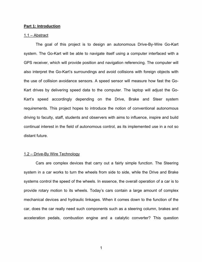
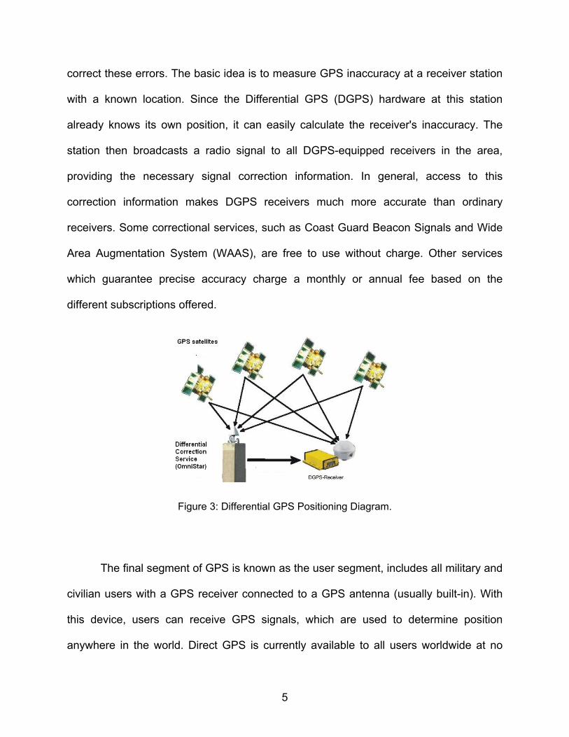
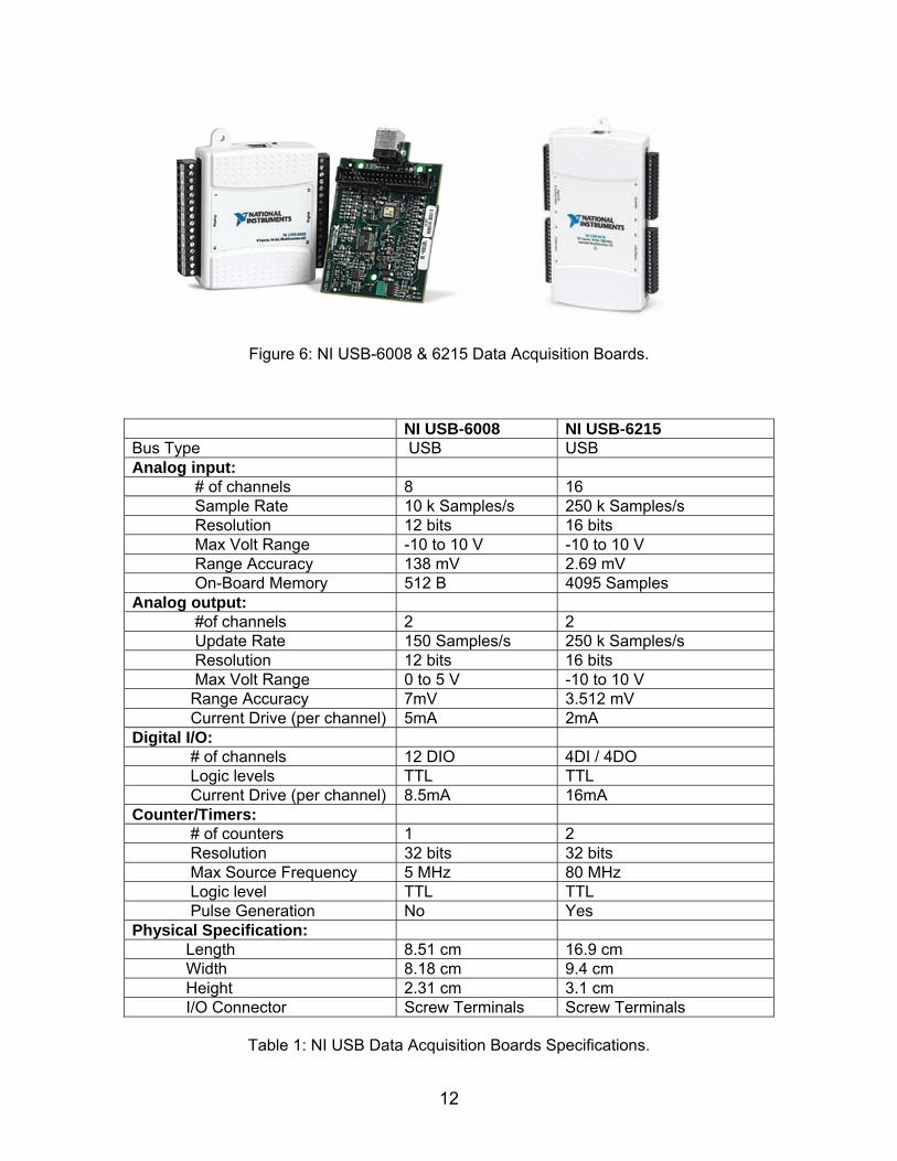
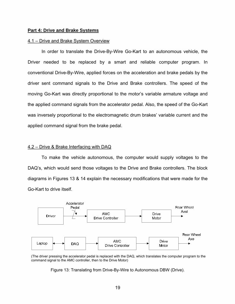
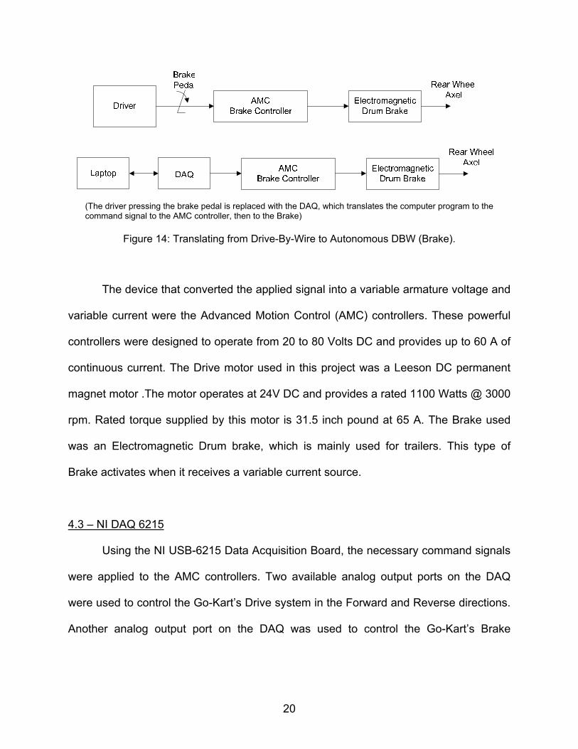
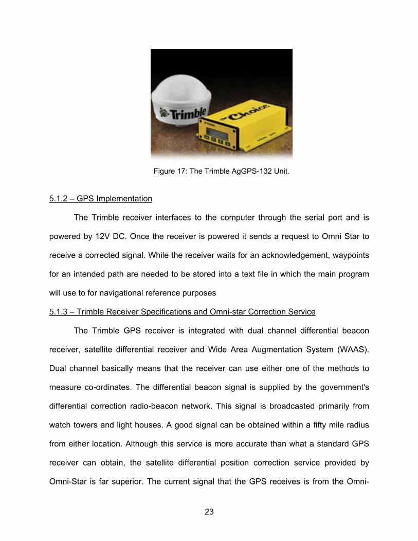
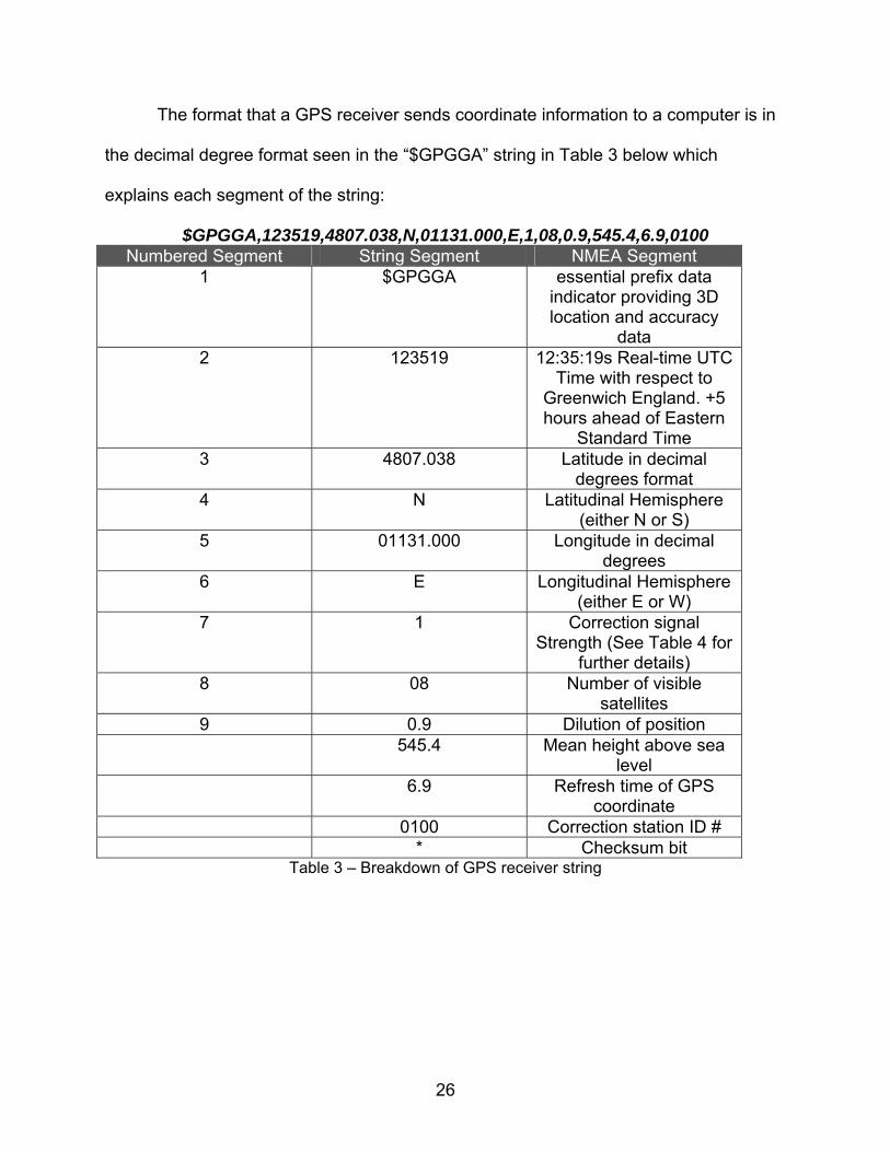
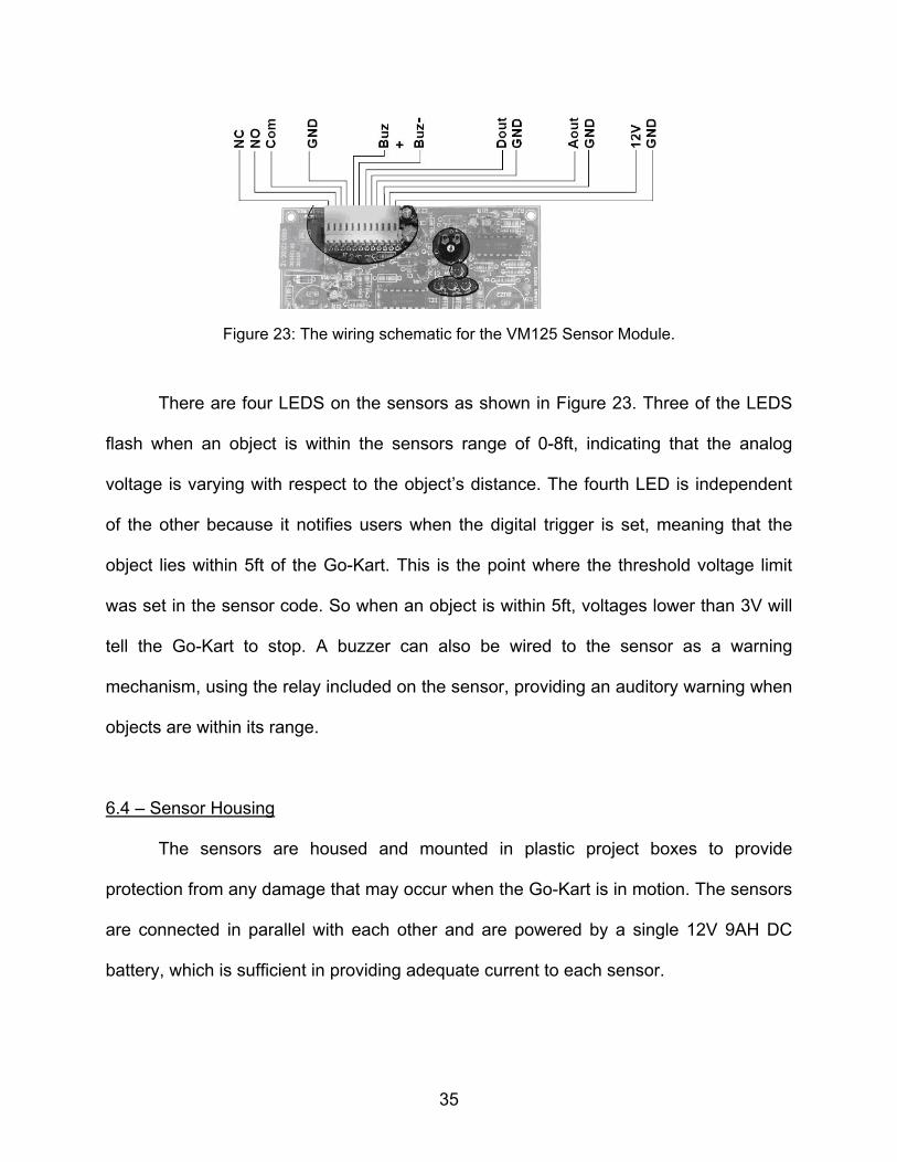
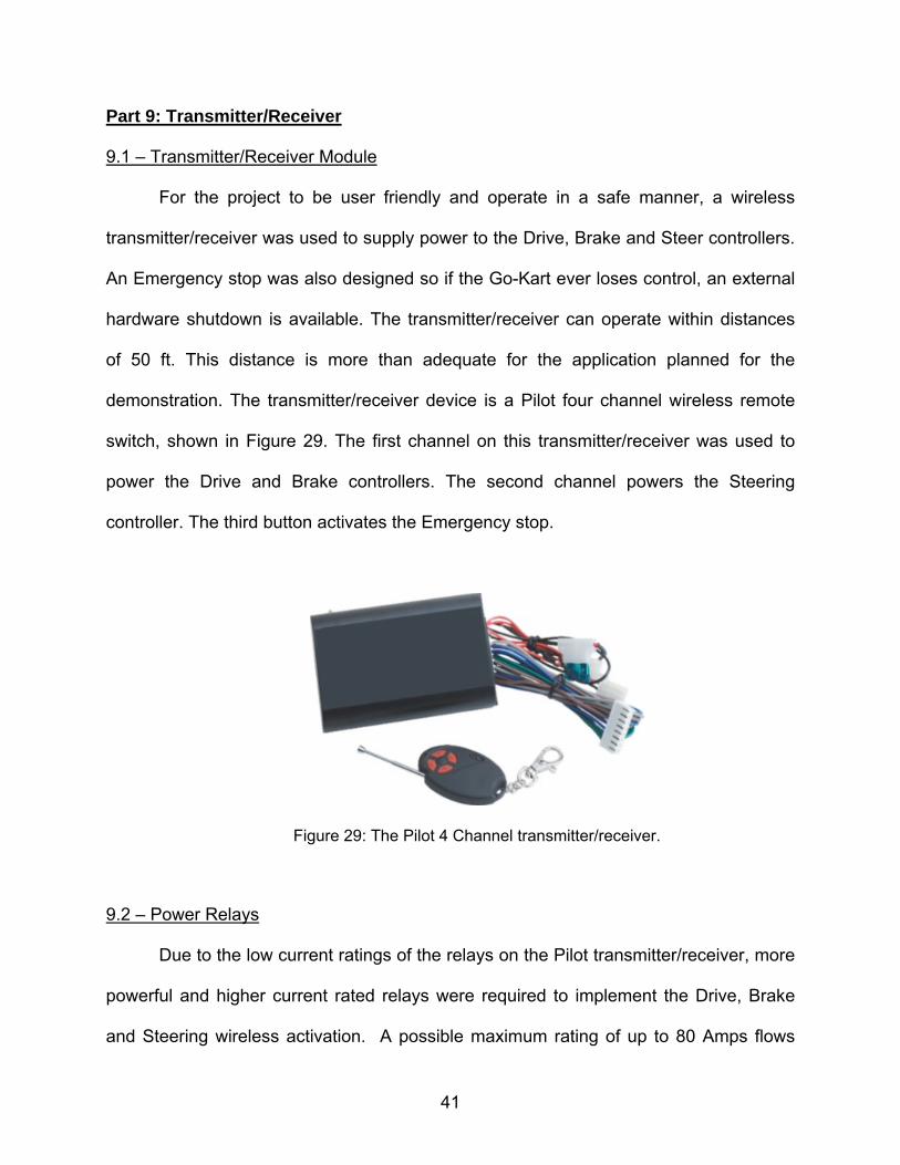
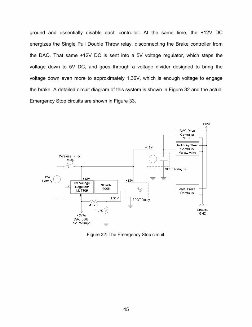
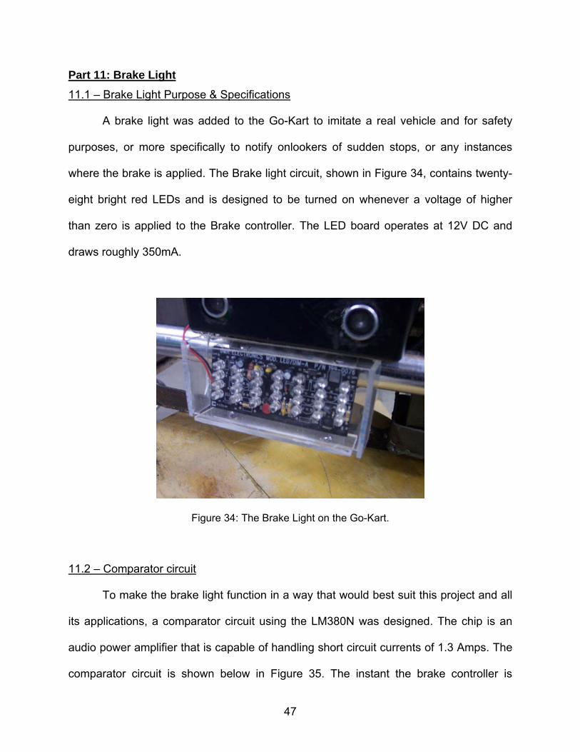
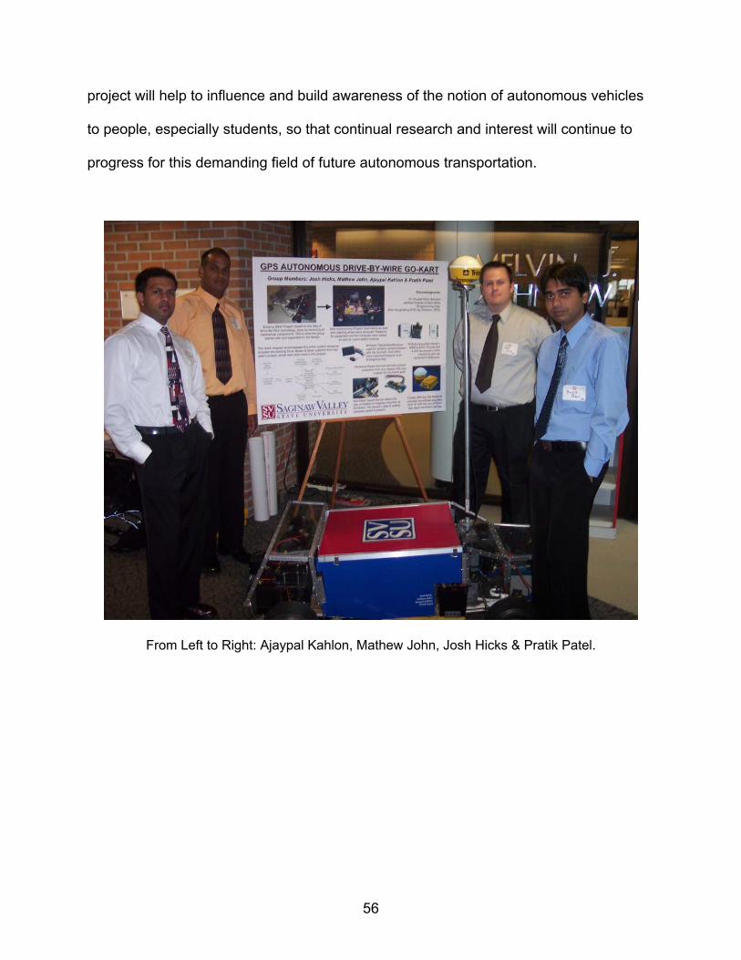
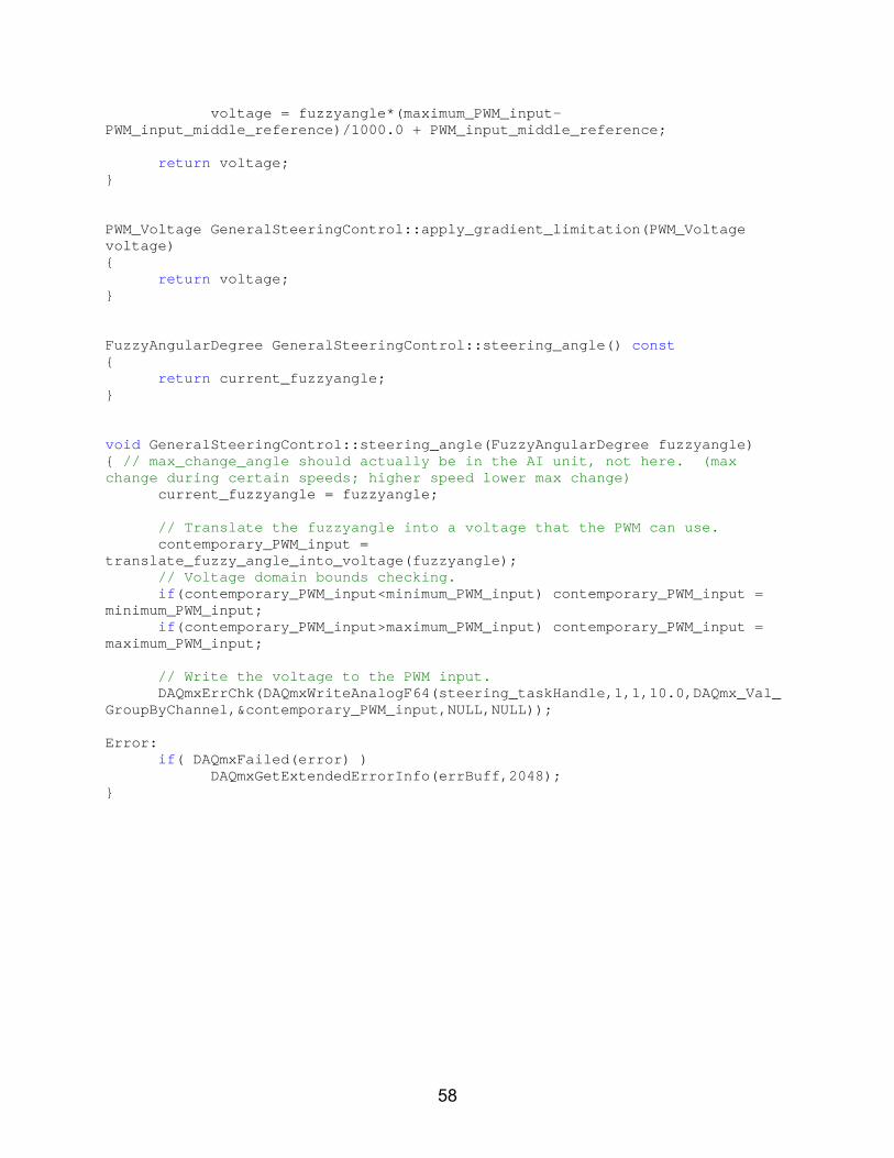
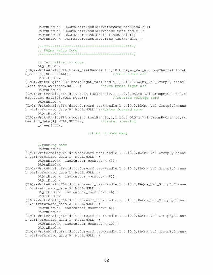
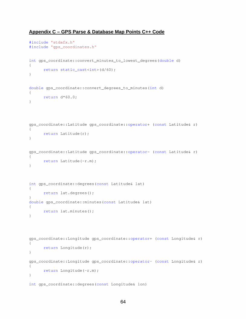
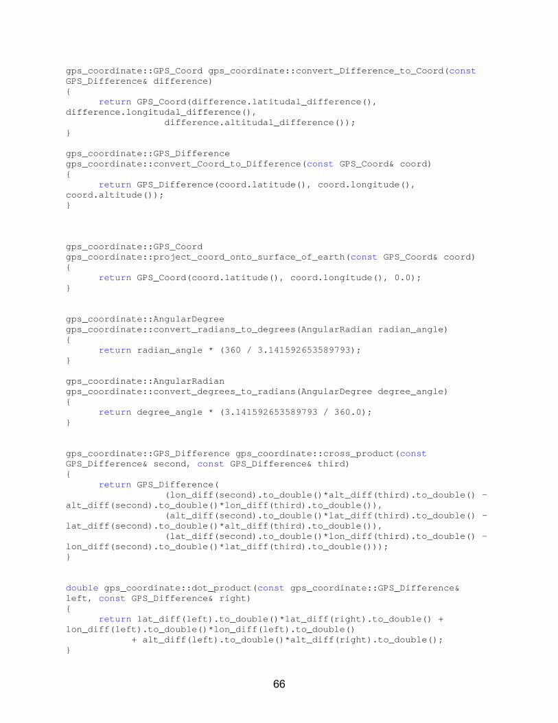
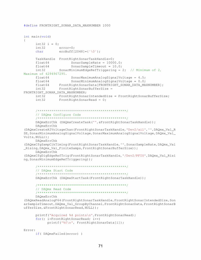
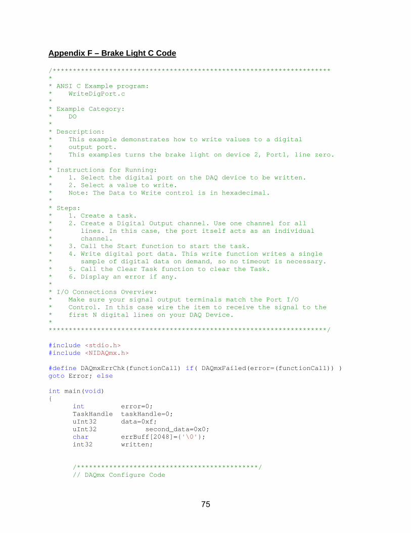