DEPARTMENT OF DEFENSE INTERFACE STANDARD FOR AIRCRAFT...
187
METRIC MIL-STD-1760D 1 August 2003 ____________________ SUPERSEDING MIL-STD-1760C 20 March 1997 DEPARTMENT OF DEFENSE INTERFACE STANDARD FOR AIRCRAFT/STORE ELECTRICAL INTERCONNECTION SYSTEM AMSC: N/A AREA: SESS DISTRIBUTION STATEMENT A. Approved for public release; distribution is unlimited.
Transcript of DEPARTMENT OF DEFENSE INTERFACE STANDARD FOR AIRCRAFT...
METRIC
MIL-STD-1760D1 August 2003____________________SUPERSEDINGMIL-STD-1760C20 March 1997
DEPARTMENT OF DEFENSEINTERFACE STANDARD
FORAIRCRAFT/STORE ELECTRICAL
INTERCONNECTION SYSTEM
AMSC: N/A AREA: SESS
DISTRIBUTION STATEMENT A. Approved for public release; distribution is unlimited.
MIL-STD-1760D
ii
FOREWORD1. This standard is approved for use by all Departments and Agencies of the Department of Defense.
2. Prior to this standard, an aircraft and the stores which it carried were typically developedindependently of each other or were developed exclusively for each other. This usually resulted in uniqueaircraft/store electrical interconnection requirements, the general proliferation of overall store interfacedesigns, low levels of interoperability, and costly aircraft modifications to achieve required store utilizationflexibility. Trends in store technology toward more complex store functions which require increasingamounts of avionics data and control information from aircraft systems were predicted to lead toinsurmountable aircraft/store interfacing problems.
3. The goal is to develop aircraft that are compatible with a wide variety of stores and stores that arecompatible with a wide variety of aircraft. This standard supports this goal by defining a standardelectrical (and fiber optic) interconnection system for aircraft and stores. This interconnection system isbased on use of a standard connector, a standard signal set and a standard serial digital data interfacefor control, monitor, and release of stores. Application of this standard to new and existing aircraft andnew stores will significantly reduce and stabilize the number and variety of signals required ataircraft/store interfaces, minimize the impact of new stores on future stores management systems, andincrease store interoperability among the services, within NATO, and with other allies.
4. Revision D does not change the fundamental MIL-STD-1760 interface. It includes newly definedrequirements for 270 VDC power and message time tagging, adds a new appendix defining GPS RFsignals, and makes other minor changes and corrections.
5. Changes between Revision C and Revision D are not marked in this document, but note referencesare added in the text, referring to notes in appendix C that explain the significant technical changes.
6. Some requirements in MIL-STD-1760 are stated by invoking other documents, including MIL-STD-1553 and MIL-DTL-38999. If tiering of requirements is limited to one level on a particular contract, it maybe necessary to include references to these second tier documents in the contractual specification.
7. The following areas are limitations of this standard:a. Requirements for mechanical, aerodynamic, logistic, and operational compatibility are not
covered.
b. Since factors such as size, shape, loads, clearances, and functional limitations are not specified,full operability of stores on aircraft cannot be assured.
c. Signals for emergency jettison of stores are not specified. However, this does not preclude theuse of the signals in this standard if they are compatible with the requirements for emergency jettison.
d. This standard does not attempt to establish the EMI/EMC requirements on the aircraft or store,although it does define an interface that is generally capable of meeting these requirements.
8. Comments, suggestions, or questions on this document should be addressed to: ASC/ENOS, 2530Loop Road West, Wright-Patterson AFB, Ohio 45433-7101 or email [email protected]. Since contact information can change, you may want to verify thecurrency of this address information using the ASSIST Online database at http://www.dodssp.daps.mil/.

MIL-STD-1760D
iii
TABLE OF CONTENTS [Note 1.]
PARAGRAPH........................................................................................................................................ PAGE
FOREWORD..................................................................................................................................................ii1. SCOPE..................................................................................................................................................... 1
1.1 Scope. ................................................................................................................................................ 11.2 Purpose. ............................................................................................................................................. 11.3 Application. ......................................................................................................................................... 1
2. APPLICABLE DOCUMENTS................................................................................................................... 22.1 General............................................................................................................................................... 22.2 Government documents. .................................................................................................................... 2
2.2.1 Specifications, standards, and handbooks.................................................................................. 22.2.2 Other government documents, drawings, and publications. ....................................................... 3
2.3 Non-Government publications............................................................................................................ 32.4 Order of precedence. ......................................................................................................................... 3
3. DEFINITIONS .......................................................................................................................................... 43.1 Definitions........................................................................................................................................... 4
3.1.1 Aircraft.......................................................................................................................................... 43.1.2 Aircraft/store Electrical Interconnection System (AEIS). ............................................................. 43.1.3 Electrical interface types.............................................................................................................. 4
3.1.3.1 Aircraft Station Interface (ASI). ............................................................................................. 43.1.3.2 Carriage Store Interface (CSI). ............................................................................................. 43.1.3.3 Carriage Store Station Interface (CSSI)................................................................................ 43.1.3.4 Mission Store Interface (MSI). .............................................................................................. 43.1.3.5 Routing Network Aircraft Subsystem Port (RNASP)............................................................. 4
3.1.4 Provisions. ................................................................................................................................... 43.1.5 Store. ........................................................................................................................................... 4
3.1.5.1 Carriage stores...................................................................................................................... 43.1.5.2 Mission stores. ...................................................................................................................... 53.1.5.3 Dispensers. ........................................................................................................................... 5
3.1.6 Stores management system. ....................................................................................................... 53.1.7 Suspension and release equipment (S&RE)............................................................................... 53.1.8 Random noise.............................................................................................................................. 53.1.9 Periodic noise. ............................................................................................................................. 53.1.10 Impulse noise............................................................................................................................. 53.1.11 Stimulated noise. ....................................................................................................................... 53.1.12 Common mode noise................................................................................................................. 53.1.13 Latency. ..................................................................................................................................... 53.1.14 Delay.......................................................................................................................................... 53.1.15 Power interruption...................................................................................................................... 5
3.2 Acronyms and abbreviations. ............................................................................................................. 64. GENERAL REQUIREMENTS.................................................................................................................. 7
4.1 Aircraft/store configurations................................................................................................................ 74.2 Interface classes. [Note 3.]................................................................................................................ 74.3. Primary interface signal set. .............................................................................................................. 7
4.3.1. High bandwidth (HB) interfaces.................................................................................................. 74.3.1.1 Type A signal requirements. ............................................................................................... 104.3.1.2 Type B signal requirements. ............................................................................................... 104.3.1.3 Signal assignment............................................................................................................... 10
4.3.2 Digital multiplex data bus interface............................................................................................ 104.3.3 Low bandwidth (LB) interface. ................................................................................................... 11
4.3.3.1 LB signal requirements. ...................................................................................................... 114.3.3.2 Signal assignment............................................................................................................... 11
4.3.4 Release consent interface. ........................................................................................................ 114.3.5 Primary interlock interface. ........................................................................................................ 13

MIL-STD-1760D
iv
PARAGRAPH........................................................................................................................................ PAGE
4.3.6 Address interface....................................................................................................................... 134.3.7 Primary structure ground. [Note 5.] .......................................................................................... 134.3.8 Primary power. [Note 6.] ........................................................................................................... 134.3.9 Fiber optic (FO) interfaces. ........................................................................................................ 14
4.4 Auxiliary power interface signal set. ................................................................................................. 144.4.1 Auxiliary power. [Note 6.].......................................................................................................... 144.4.2 Auxiliary interlock interface. ....................................................................................................... 144.4.3 Auxiliary structure ground. [Note 5.] ......................................................................................... 14
4.5 Interface connectors......................................................................................................................... 145. DETAILED REQUIREMENTS ............................................................................................................... 15
5.1 Aircraft requirements. ....................................................................................................................... 155.1.1 Aircraft HB interfaces................................................................................................................. 15
5.1.1.1 Minimum transfer capacity. ................................................................................................. 155.1.1.2 Type A signal path requirements. ....................................................................................... 155.1.1.3 Type B signal path requirements. ....................................................................................... 165.1.1.4 Ground reference. ............................................................................................................... 16
5.1.2 Aircraft digital data bus interface. .............................................................................................. 245.1.2.1 Functional characteristics. .................................................................................................. 245.1.2.2 Electrical characteristics. .................................................................................................... 24
5.1.3 Aircraft LB interface. .................................................................................................................. 255.1.3.1 Minimum transfer capacity. ................................................................................................. 255.1.3.2 Input/output impedance....................................................................................................... 255.1.3.3 Insertion gain....................................................................................................................... 255.1.3.4 Equalization requirements. ................................................................................................. 255.1.3.5 Signal path dc offset............................................................................................................ 265.1.3.6 Noise. .................................................................................................................................. 265.1.3.7 Ground reference. ............................................................................................................... 26
5.1.4 Aircraft release consent interface. ............................................................................................. 275.1.4.1 Voltage level........................................................................................................................ 275.1.4.2 Current level. ....................................................................................................................... 285.1.4.3 Stabilization time. ................................................................................................................ 285.1.4.4 Enable lead time. ................................................................................................................ 285.1.4.5 Inhibit delay. ........................................................................................................................ 285.1.4.6 Ground reference. ............................................................................................................... 28
5.1.5 Aircraft interlock interface. ......................................................................................................... 285.1.6 Aircraft address interface........................................................................................................... 28
5.1.6.1 Address assignment............................................................................................................ 285.1.6.2 Address signal..................................................................................................................... 295.1.6.3 Logic thresholds. ................................................................................................................. 295.1.6.4 Response characteristics.................................................................................................... 295.1.6.5 Address isolation................................................................................................................. 29
5.1.7 Aircraft structure ground. [Note 12.] ......................................................................................... 295.1.8 Aircraft 28 V dc power interface. ............................................................................................... 30
5.1.8.1 Independent control. ........................................................................................................... 305.1.8.2 Voltage level. [Note 13.] ..................................................................................................... 305.1.8.3 Current capacity. ................................................................................................................. 305.1.8.4 Overcurrent protection. ....................................................................................................... 305.1.8.5 Off-state leakage current. ................................................................................................... 305.1.8.6 Stabilization time. ................................................................................................................ 335.1.8.7 Ground reference. ............................................................................................................... 335.1.8.8 Power application................................................................................................................ 33
5.1.9 Aircraft 115/200 V ac power interface. ...................................................................................... 335.1.9.1 Independent control and dead facing.................................................................................. 335.1.9.2 Voltage level. [Note 13.] ..................................................................................................... 34

MIL-STD-1760D
v
PARAGRAPH........................................................................................................................................ PAGE
5.1.9.3 Current capacity. ................................................................................................................. 345.1.9.4 Overcurrent protection. ....................................................................................................... 345.1.9.5 Off-state leakage current. ................................................................................................... 345.1.9.6 Stabilization time. ................................................................................................................ 345.1.9.7 Phase rotation. .................................................................................................................... 345.1.9.8 Load power factor. .............................................................................................................. 345.1.9.9 Phase power unbalance. .................................................................................................... 355.1.9.10 Ground reference. ............................................................................................................. 355.1.9.11 Power application.............................................................................................................. 35
5.1.10 Aircraft 270 V dc power interface. [Note 17.].......................................................................... 355.1.10.1 Independent control and dead facing. .............................................................................. 355.1.10.2 Voltage level...................................................................................................................... 355.1.10.3 Current capacity. ............................................................................................................... 365.1.10.4 Overcurrent protection. ..................................................................................................... 365.1.10.5 Off-state leakage current. ................................................................................................. 365.1.10.6 Stabilization time. .............................................................................................................. 365.1.10.7 Ground reference. ............................................................................................................. 365.1.10.8 Power application.............................................................................................................. 36
5.1.11 Aircraft fiber optic interface. ..................................................................................................... 365.1.12 Initialization. ............................................................................................................................. 36
5.1.12.1 Pre-initialization conditions. .............................................................................................. 375.1.12.2 Power application. [Note 18.] ........................................................................................... 375.1.12.3 First communication. ......................................................................................................... 37
5.2 Mission store requirements (measured at the MSI). ........................................................................ 375.2.1 Mission store HB interfaces. ...................................................................................................... 37
5.2.1.2 Electrical characteristics (type A)........................................................................................ 375.2.1.3 Electrical characteristics (type B)........................................................................................ 375.2.1.4 Ground reference. ............................................................................................................... 37
5.2.2 Mission store data bus interface................................................................................................ 375.2.2.1 Functional characteristics. .................................................................................................. 385.2.2.2 Electrical characteristics. .................................................................................................... 38
5.2.3 Mission store LB interface. ........................................................................................................ 385.2.3.1 Input/output impedance....................................................................................................... 385.2.3.2 Ground reference. ............................................................................................................... 38
5.2.4 Mission store release consent interface. ................................................................................... 395.2.4.1 Voltage level........................................................................................................................ 395.2.4.2 Current level. ....................................................................................................................... 395.2.4.3 Stabilization time. ................................................................................................................ 395.2.4.4 Enable lead time. ................................................................................................................ 395.2.4.5 Inhibit lead time. .................................................................................................................. 395.2.4.6 Ground reference. ............................................................................................................... 39
5.2.5 Mission store interlock interface. ............................................................................................... 405.2.6 Mission store address interface................................................................................................. 40
5.2.6.1 Address assignment............................................................................................................ 405.2.6.2 Address signal..................................................................................................................... 405.2.6.3 Logic threshold.................................................................................................................... 415.2.6.4 Response characteristics.................................................................................................... 41
5.2.7 Mission store structure ground. [Note 19.]................................................................................ 415.2.8 Mission store 28 V dc power interface....................................................................................... 41
5.2.8.1 Voltage level........................................................................................................................ 415.2.8.2 Load current. ....................................................................................................................... 415.2.8.3 Load isolation. ..................................................................................................................... 425.2.8.4 Overcurrent compatibility. ................................................................................................... 425.2.8.5 Off-state leakage current. ................................................................................................... 42
MIL-STD-1760D
vi
PARAGRAPH........................................................................................................................................ PAGE
5.2.8.6 Stabilization time. ................................................................................................................ 425.2.8.7 Ground reference. ............................................................................................................... 425.2.8.8 Power utilization. ................................................................................................................. 42
5.2.9 Mission store 115/200 V ac power interface. ............................................................................ 425.2.9.1 Voltage level........................................................................................................................ 425.2.9.2 Load current. ....................................................................................................................... 435.2.9.3 Load isolation. [Note 20.] .................................................................................................... 435.2.9.4 Overcurrent compatibility. ................................................................................................... 435.2.9.5 Off-state leakage current. ................................................................................................... 435.2.9.6 Stabilization time. ................................................................................................................ 435.2.9.7 Load power factor. .............................................................................................................. 435.2.9.8 Phase unbalance. ............................................................................................................... 435.2.9.9 Ground reference. [Note 21.] ............................................................................................. 435.2.9.10 Power utilization. ............................................................................................................... 43
5.2.10 Mission store 270 V dc power interface. [Note 17.]................................................................ 445.2.10.1 Voltage level...................................................................................................................... 445.2.10.2 Load current. ..................................................................................................................... 445.2.10.3 Load isolation. ................................................................................................................... 445.2.10.4 Overcurrent compatibility. ................................................................................................. 445.2.10.5 Off-state leakage current. ................................................................................................. 445.2.10.6 Stabilization time. .............................................................................................................. 445.2.10.7 Ground reference. ............................................................................................................. 445.2.10.8 Power utilization. ............................................................................................................... 45
5.2.11 Mission store fiber optic interface. ........................................................................................... 455.2.12 Store initialization..................................................................................................................... 45
5.2.12.1 Pre-initialization conditions. .............................................................................................. 455.2.12.2 Power application. [Note 18.] ........................................................................................... 455.2.12.3 Address determination. ..................................................................................................... 455.2.12.4 First response. .................................................................................................................. 455.2.12.5 First required non-busy response. .................................................................................... 45
5.3 Carriage store requirements. ........................................................................................................... 465.3.1 Carriage store HB interfaces. .................................................................................................... 46
5.3.1.1 Minimum transfer capacity. ................................................................................................. 465.3.1.2 Type A signal path characteristics. ..................................................................................... 465.3.1.3 Signal path electrical characteristics (type B). .................................................................... 475.3.1.4 Ground reference (type A). ................................................................................................. 475.3.1.5 Ground reference (type B). ................................................................................................. 48
5.3.2 Carriage store data bus interface. ............................................................................................. 485.3.2.1 CSI. ..................................................................................................................................... 485.3.2.2 CSSI. ................................................................................................................................... 48
5.3.3 Carriage store LB interface........................................................................................................ 485.3.3.1 Minimum transfer capacity. ................................................................................................. 495.3.3.2 Input/output impedance....................................................................................................... 495.3.3.3 Insertion gain....................................................................................................................... 495.3.3.4 Equalization......................................................................................................................... 495.3.3.5 Signal path dc offset............................................................................................................ 495.3.3.6 Noise. .................................................................................................................................. 495.3.3.7 Ground reference. ............................................................................................................... 50
5.3.4 Carriage store release consent interface. ................................................................................. 515.3.4.1 CSI. ..................................................................................................................................... 515.3.4.2 CSSI. ................................................................................................................................... 515.3.4.3 CSI to CSSI transfer............................................................................................................ 51
5.3.5 Carriage store interlock interface............................................................................................... 515.3.5.1 CSI. ..................................................................................................................................... 51
MIL-STD-1760D
vii
PARAGRAPH........................................................................................................................................ PAGE
5.3.5.2 CSSI. ................................................................................................................................... 515.3.5.3 Isolation. .............................................................................................................................. 51
5.3.6 Carriage store address interface. .............................................................................................. 515.3.6.1 CSI. ..................................................................................................................................... 525.3.6.2 CSSI. ................................................................................................................................... 52
5.3.7 Carriage store structure ground. [Note 19.] .............................................................................. 525.3.7.1 CSI Structure Ground Characteristics. ............................................................................... 525.3.7.2 CSSI Structure Ground Characteristics. ............................................................................. 52
5.3.8 Carriage store 28 V dc power interface. .................................................................................... 525.3.8.1 CSI. ..................................................................................................................................... 525.3.8.2 CSSI. ................................................................................................................................... 52
5.3.9 Carriage store 115/200 V ac power interfaces. ......................................................................... 525.3.9.1 CSI. ..................................................................................................................................... 535.3.9.2 CSSI. ................................................................................................................................... 535.3.10 Carriage store 270 V dc power interfaces. [Note 17.]......................................................... 545.3.10.1 CSI. ................................................................................................................................... 545.3.10.2 CSSI. ................................................................................................................................. 54
5.3.11 Carriage store fiber optic interface. ......................................................................................... 545.3.12 Carriage store initialization. ..................................................................................................... 54
5.4 Umbilical cable requirements. .......................................................................................................... 545.4.1 Primary umbilical HB interfaces................................................................................................. 545.4.2 Primary umbilical data bus interface.......................................................................................... 545.4.3 Primary umbilical LB interface. .................................................................................................. 555.4.4 Primary umbilical release consent interface.............................................................................. 555.4.5 Umbilical interlock interface. ...................................................................................................... 555.4.6 Primary umbilical address interface........................................................................................... 555.4.7 Umbilical structure ground. ........................................................................................................ 555.4.8 Umbilical 28 V dc power interface. ............................................................................................ 555.4.9 Umbilical 115 V ac power interface. .......................................................................................... 555.4.10 Umbilical 270 V dc power interface. [Note 18.] ...................................................................... 555.4.11 Primary umbilical fiber optic interface...................................................................................... 555.4.12 Umbilical gross shield. ............................................................................................................. 55
5.5 Power interface interrupts. ............................................................................................................... 565.5.1 Mission store compatibility. [Note 22.] ...................................................................................... 565.5.2 Carriage store compatibility. [Note 22.] .................................................................................... 565.5.3 Aircraft compatibility. [Note 22.] ................................................................................................ 56
5.5.3.1 Full initialization................................................................................................................... 565.5.3.2 Partial initialization. ............................................................................................................. 56
5.5.4 Store power interrupt notification............................................................................................... 565.6 Connector characteristics................................................................................................................. 56
5.6.1 Primary interface connectors. .................................................................................................... 565.6.2 Auxiliary power interface connector........................................................................................... 575.6.3 Connector receptacle................................................................................................................. 575.6.4 Plugged cavities. [Note 23.] ...................................................................................................... 575.6.5 Umbilical primary interface connectors...................................................................................... 575.6.6 Umbilical auxiliary interface connectors. [Note 24.].................................................................. 575.6.7 Connector keyway orientation. .................................................................................................. 57
5.6.7.1 ASI and CSSI. ..................................................................................................................... 575.6.7.2 MSI and CSI. ....................................................................................................................... 585.6.7.3 Umbilical cable. ................................................................................................................... 58
5.6.8 Connector location..................................................................................................................... 585.6.8.1 ASI and CSSI. ..................................................................................................................... 585.6.8.2 MSI and CSI. ....................................................................................................................... 58

MIL-STD-1760D
viii
PARAGRAPH........................................................................................................................................ PAGE
6. NOTES................................................................................................................................................... 636.1 Intended use..................................................................................................................................... 63
6.1.1 Implementation. ......................................................................................................................... 636.2 Issue of DoDISS. .............................................................................................................................. 636.3 International standardization agreements. ....................................................................................... 636.4 Tailoring guidance. ........................................................................................................................... 636.5 Keyword listing. ................................................................................................................................ 636.6 Changes from previous issue........................................................................................................... 64
A.1. SCOPE ............................................................................................................................................... 65A.1.1 Purpose......................................................................................................................................... 65
A.2. APPLICABLE DOCUMENTS ............................................................................................................. 65A.2.1 References.................................................................................................................................... 65A.2.2 Government documents, drawings and publications.................................................................... 65
A.3. DEFINITIONS, ACRONYMS AND ABBREVIATIONS ....................................................................... 65A.3.1 Definitions. .................................................................................................................................... 65
A.3.1.1 Navstar global positioning system (GPS)............................................................................... 65A.3.1.2 L1 and L2................................................................................................................................ 65A.3.1.3 Power gain.............................................................................................................................. 65A.3.1.4 Correlation loss. ..................................................................................................................... 65A.3.1.5 Effective gain. ......................................................................................................................... 65A.3.1.6 Figure of merit. ....................................................................................................................... 66A.3.1.7 Group delay. ........................................................................................................................... 66A.3.1.8 Aircraft station GPS RF output. .............................................................................................. 66A.3.1.9 L1_P(Y) signal. ....................................................................................................................... 66A.3.1.10 L2_P(Y) signal. ..................................................................................................................... 66A.3.1.11 L1_C/A signal. ...................................................................................................................... 66
A.3.2 Acronyms and abbreviations......................................................................................................... 66A.4. GENERAL REQUIREMENTS ............................................................................................................ 66
A.4.1 Aircraft/store configurations. ......................................................................................................... 66A.4.2 GPS RF signal requirements. ....................................................................................................... 67
A.5. AIRCRAFT REQUIREMENTS............................................................................................................ 67A.5.1 Voltage standing wave ratio (VSWR). .......................................................................................... 68A.5.2 Effective gain................................................................................................................................. 68A.5.3 Group delay................................................................................................................................... 68A.5.4 Group delay uncertainty................................................................................................................ 68A.5.5 Figure of Merit. .............................................................................................................................. 68A.5.6 Signal path dc offset. .................................................................................................................... 68
A.6. MISSION STORE REQUIREMENTS................................................................................................. 68A.6.1 Voltage standing wave ratio (VSWR). .......................................................................................... 68A.6.2 Signal power. ................................................................................................................................ 68A.6.3 Signal to noise ratio. ..................................................................................................................... 69A.6.4 Signal path dc offset. .................................................................................................................... 69
B.1 SCOPE ................................................................................................................................................ 71B.1.1 Purpose......................................................................................................................................... 71
B.2 APPLICABLE DOCUMENTS .............................................................................................................. 71B.2.1 References.................................................................................................................................... 71B.2.2 Government documents................................................................................................................ 71B.2.3 Other Government documents, drawings, and publications......................................................... 71B.2.4 Non-Government publications. ..................................................................................................... 72
B.2.4.1 AMERICAN NATIONAL STANDARDS INSTITUTE .............................................................. 72B.2.4.2 INTERNATIONAL STANDARDS ORGANIZATION............................................................... 72B.2.4.3 SOCIETY OF AUTOMOTIVE ENGINEERS .......................................................................... 72

MIL-STD-1760D
ix
PARAGRAPH........................................................................................................................................ PAGE
B.3 DEFINITIONS...................................................................................................................................... 72B.3.1 Definitions. .................................................................................................................................... 72
B.3.1.1 Data entity. ............................................................................................................................. 72B.3.1.2 Data set. ................................................................................................................................. 72B.3.1.3 Data validity. ........................................................................................................................... 72B.3.1.4 Mass data transfer.................................................................................................................. 72
B.3.1.4.1 Back-to-back transfer. ..................................................................................................... 72B.3.1.4.2 Block. ............................................................................................................................... 73B.3.1.4.3 Download......................................................................................................................... 73B.3.1.4.4 File. .................................................................................................................................. 73B.3.1.4.5 Record. ............................................................................................................................ 73B.3.1.4.6 Upload.............................................................................................................................. 73B.3.1.4.7 Buffer. .............................................................................................................................. 73
B.3.2 Acronyms and abbreviations......................................................................................................... 73B.4 REQUIREMENTS................................................................................................................................ 73
B.4.1 Communication rules. ................................................................................................................... 73B.4.1.1 Command word. ..................................................................................................................... 73
B.4.1.1.1 Remote terminal address field......................................................................................... 73B.4.1.1.2 Subaddress/mode field. ................................................................................................... 73B.4.1.1.3 Mode commands. ............................................................................................................ 73
B.4.1.2 Status word............................................................................................................................. 74B.4.1.2.1 Service request bit. .......................................................................................................... 75B.4.1.2.2 Busy bit. ........................................................................................................................... 75B.4.1.2.3 Subsystem flag bit. .......................................................................................................... 75B.4.1.2.4 Terminal flag bit. .............................................................................................................. 75
B.4.1.3 Data words. ............................................................................................................................ 75B.4.1.4 Internal state change.............................................................................................................. 75B.4.1.5 Protocol execution.................................................................................................................. 75
B.4.1.5.1 Protocol checks. .............................................................................................................. 75B.4.1.5.2 Checksum requirement. .................................................................................................. 75B.4.1.5.3 Execution time. ................................................................................................................ 76B.4.1.5.4 Service request notification. ............................................................................................ 77B.4.1.5.5 Request servicing. ........................................................................................................... 77B.4.1.5.6 Vector word demand........................................................................................................ 77B.4.1.5.7 General form of service request routine. ......................................................................... 77B.4.1.5.8 Mass data transfer. .......................................................................................................... 77B.4.1.5.9 Carriage store routing. ..................................................................................................... 77B.4.1.5.10 Data consistency. .......................................................................................................... 77B.4.1.5.11 Broadcast....................................................................................................................... 77B.4.1.5.12 Time tagging. [Note 29.] ............................................................................................... 78
B.4.2 Message requirements. ................................................................................................................ 78B.4.2.1 Base message data format. ................................................................................................... 78
B.4.2.1.1 Data word 1. .................................................................................................................... 78B.4.2.1.2 Data words 2-32 and 2-30. .............................................................................................. 78
B.4.2.2 Standard messages. .............................................................................................................. 79B.4.2.2.1 Store control. ................................................................................................................... 79B.4.2.2.2 Store monitor. .................................................................................................................. 79B.4.2.2.3 Store description.............................................................................................................. 79B.4.2.2.4 Nuclear weapon control. .................................................................................................. 79B.4.2.2.5 Nuclear weapon monitor.................................................................................................. 79B.4.2.2.6 Aircraft description. ........................................................................................................... 79
B.4.2.3 Mass data transfer messages. ............................................................................................... 80B.4.2.3.1 File Structure. .................................................................................................................. 80B.4.2.3.2 Message formats. ............................................................................................................ 80

MIL-STD-1760D
x
PARAGRAPH........................................................................................................................................ PAGE
B.4.2.3.3 MDT file/record checksum............................................................................................... 85B.4.2.3.4 Modes of operation. ......................................................................................................... 85
B.4.2.4 Protocol for time tagging. ....................................................................................................... 92B.4.2.4.1 Time tag reference time. [Note 29.] ................................................................................ 93B.4.2.4.2 Aircraft system time at reset. ........................................................................................... 93B.4.2.4.3 Receive time tag. ............................................................................................................. 93B.4.2.4.4. Transmit time tag. [Note 29.] ......................................................................................... 93
B.4.3 Standard data entities. .................................................................................................................. 94

MIL-STD-1760D
xi
FIGURES .............................................................................................................................................. PAGE
FIGURE 1. Aircraft-store configuration examples........................................................................................ 8FIGURE 2. Primary interface signal set. [Note 4.] ...................................................................................... 9FIGURE 3. Auxiliary power signal set. [Note 4.] ....................................................................................... 10FIGURE 4. Conceptual HB and LB interface configurations. .................................................................... 12FIGURE 5. Cosine-squared T signal requirements. .................................................................................. 17FIGURE 6. Cosine-squared 2T signal requirements. ................................................................................ 18FIGURE 7. 2T Bar signal requirements (1.0V). ......................................................................................... 19FIGURE 8. 2T Bar signal requirements (1.3V). ......................................................................................... 20FIGURE 9. Gain misequalization envelope. [Note 10.]............................................................................ 21FIGURE 10. Random noise weighting function. ........................................................................................ 21FIGURE 11. Periodic noise weighting function.......................................................................................... 22FIGURE 12. Common mode noise weighting function. ............................................................................. 22FIGURE 13. Equivalent circuits of HB interfaces....................................................................................... 23FIGURE 14. ASI output waveform envelope. ............................................................................................ 25FIGURE 15. Gain misequalization envelope (aircraft, LB). ....................................................................... 26FIGURE 16. Equivalent circuits for LB interfaces. ..................................................................................... 27FIGURE 17. Primary interface current level. [Note 15.]............................................................................ 31FIGURE 18. Auxiliary interface current level. [Note 15.]........................................................................... 32FIGURE 19. Stabilization time. .................................................................................................................. 33FIGURE 20. Power factor limits. ................................................................................................................ 35FIGURE 21. Equivalent circuits of carriage store HB Type A signal paths. .............................................. 48FIGURE 22. Maximum gain misequalization envelope (LB, carriage store). ............................................ 49FIGURE 23. Equivalent circuits for LB carriage store signal paths. .......................................................... 50FIGURE 24. Carriage store voltage drop diagram..................................................................................... 53FIGURE 25. Connector orientation. ........................................................................................................... 62FIGURE A- 1. GPS RF Interface configurations........................................................................................ 67FIGURE B- 1. Examples of general form of service request protocol. ...................................................... 95FIGURE B- 2. Aircraft body axis system.................................................................................................... 96FIGURE B- 3. Earth axis systems.............................................................................................................. 97FIGURE B- 4. Aircraft, target and waypoint position XYZ to fixed point.................................................... 98FIGURE B- 5. Earth aircraft alignment....................................................................................................... 99FIGURE B- 6. Aircraft-store alignment..................................................................................................... 100FIGURE B- 7. Store body axis system..................................................................................................... 102FIGURE B- 8. Target and waypoint position XYZ from current position. ................................................ 102FIGURE B- 9. Target position/store trajectory (polar). ............................................................................ 103FIGURE B- 10. Target sector and segment position. .............................................................................. 104

MIL-STD-1760D
xii
TABLES................................................................................................................................................. PAGE
TABLE I. Carriage store HB signal transfer. .............................................................................................. 46TABLE II. Primary signal set connector contacts/termini and seal plugs. ................................................. 59TABLE III. Primary signal set contact functional assignment. [Note 25.].................................................. 60TABLE IV. Auxiliary power signal set connector contacts and seal plugs. [Note 26.] .............................. 61TABLE V. Auxiliary power signal set contact functional assignment......................................................... 61TABLE B- I. Subaddress/mode field application...................................................................................... 105TABLE B- II. Vector word (asynchronous message demand) format...................................................... 107TABLE B- III. Vector word (asynchronous action demand) format.......................................................... 108TABLE B- IV. DELETED .......................................................................................................................... 108TABLE B- V. DELETED. .......................................................................................................................... 108TABLE B- VI. DELETED. .......................................................................................................................... 108TABLE B- VII. Base message format (BC-RT transfer)........................................................................... 109TABLE B- VIII. Base message format (RT-BC transfer).......................................................................... 110TABLE B- IX. Base message format (RT-RT transfer). ........................................................................... 111TABLE B- X. Header word. ...................................................................................................................... 112TABLE B- XI. Store control (BC-RT transfer). 1/ ................................................................................... 113TABLE B- XII. Store monitor (RT-BC transfer). 1/ ................................................................................. 115TABLE B- XIII. Store description message. 1/ ...................................................................................... 116TABLE B- XIV. Country code................................................................................................................... 117TABLE B- XV. Store identity (binary). ...................................................................................................... 118TABLE B- XVI. Store or aircraft identity (ASCII). ..................................................................................... 119TABLE B- XVII. Transfer Control (TC) message format. ......................................................................... 120TABLE B- XVIII. Instruction word............................................................................................................. 121TABLE B- XIX. Allowable instruction type field bit states. [Note 31.]...................................................... 122TABLE B- XX. Subaddress select............................................................................................................ 123TABLE B- XXI. Dual binary number......................................................................................................... 124TABLE B- XXII. Transfer Monitor (TM) message format. ........................................................................ 125TABLE B- XXIII. Transfer mode status. ................................................................................................... 126TABLE B- XXIV. Transfer Data (TD) message format. 1/..................................................................... 127TABLE B- XXV. Allowable mode status field bit states............................................................................ 128TABLE B- XXVI. Data entity list. [Note 32.]............................................................................................. 129TABLE B- XXVII. Linear data entities. ..................................................................................................... 145TABLE B- XXVIII. 2's complement format. .............................................................................................. 147TABLE B- XXIX. Unsigned format. .......................................................................................................... 148TABLE B- XXX. Binary scientific notation format..................................................................................... 149TABLE B- XXXI. Invalidity word. .............................................................................................................. 150TABLE B- XXXII. Critical control 1. .......................................................................................................... 151TABLE B- XXXIII. Critical control 2. ......................................................................................................... 153TABLE B- XXXIV. Critical authority.......................................................................................................... 154TABLE B- XXXV. Critical monitor 1. ........................................................................................................ 155TABLE B- XXXVI. Critical monitor 2. ....................................................................................................... 156TABLE B- XXXVII. Fuzing mode 1........................................................................................................... 157TABLE B- XXXVIII. Fuzing/arming mode status 1................................................................................... 158TABLE B- XXXIX. Protocol status............................................................................................................ 159TABLE B- XL. ASCII packed.................................................................................................................... 160TABLE B- XLI. Discriminator description. ................................................................................................ 161TABLE B- XLII. Header word definition.................................................................................................... 162TABLE B- XLIII. Fuzing mode 2............................................................................................................... 163TABLE B- XLIV. Fuzing/arming mode status 2........................................................................................ 164TABLE B- XLV. Dispersion data word. .................................................................................................... 165TABLE B- XLVI. Two zone format. .......................................................................................................... 166TABLE B- XLVII. Aircraft description message. 1/................................................................................. 167TABLE B- XLVIII. Store station number and pylon/bay identity............................................................... 168

MIL-STD-1760D
xiii
APPENDICES ....................................................................................................................................... PAGE
APPENDIX A. Additional Interface Requirements for GPS RF Signals .................................................... 65APPENDIX B. Digital Data Bus Communication Rules and Message Requirements............................... 71APPENDIX C. Annotations Explaining Differences From Revision C Notice 1....................................... 169
CONCLUDING MATERIAL....................................................................................................................... 173

MIL-STD-1760D
xiv
This page intentionally blank.

MIL-STD-1760D
1
1. SCOPE
1.1 Scope.This standard defines implementation requirements for the Aircraft/Store Electrical (and fiber optic)Interconnection System (AEIS) in aircraft and stores. This interconnection system provides a commoninterfacing capability for the operation and employment of stores on aircraft, and includes:
a. The electrical (and fiber optic) interfaces at aircraft store stations, the interface on mission stores,the interface on carriage stores, and the characteristics of umbilical cables.
b. Interrelationships between aircraft and store interfaces.
c. Interrelationships between the interfaces at different store stations on an aircraft.
1.2 Purpose.The purpose of this standard is to minimize the proliferation of electrical and optical interfacing variationsrequired in aircraft for operating stores and minimize the proliferation of electrical and optical interfacingvariations required in stores to interface with aircraft. The implementation of this standard shouldenhance the interoperability of stores and aircraft by defining specific electrical/optical, logical, andphysical requirements for the AEIS.
1.3 Application.This standard applies to all aircraft and stores that electrically interface with each other. This coverageencompasses stores and aircraft presently in concept development stages and future aircraft and storedevelopment. This standard also applies to existing aircraft which are required to carry MIL-STD-1760compatible stores.

MIL-STD-1760D
2
2. APPLICABLE DOCUMENTS
2.1 General.The documents listed in this section are specified in sections 3, 4, and 5 of this standard. This sectiondoes not include documents cited in other sections of this standard or recommended for additionalinformation or as examples. While every effort has been made to ensure the completeness of this list,document users are cautioned that they must meet all specified requirements documents cited in sections3, 4, and 5 of this standard, whether or not they are listed.
2.2 Government documents.2.2.1 Specifications, standards, and handbooks.The following specifications, standards, and handbooks form a part of this document to the extentspecified herein. Unless otherwise specified, the issues of these documents are those cited in thesolicitation or contract.
SPECIFICATIONS [Note 2.]
Department of DefenseMIL-C-17/94 Cable, Radio Frequency Flexible Coaxial 75 Ohms M17/094 RGG179MIL-C-17/113 Cable, Radio Frequency, Flexible, Coaxial, 50 Ohms, M17/113-RG316MIL-A-8591 Airborne Stores, Suspension Equipment and Aircraft-Store Interface
(Carriage Phase); General Design Criteria ForMIL- DTL-38999 Connectors, Electrical, Circular, Miniature, High Density, Quick Disconnect
(Bayonet, Threaded and Breech Coupling), Environment Resistant,Removable Crimp and Hermetic Solder Contacts, General Specification For
MIL-C-39029 Contacts, Electrical Connector, General Specification ForMIL-C-39029/28 Contacts, Electrical Connector, Pin, Crimp Removable, Shielded, Size 12
(For MIL-DTL-38999 Series I, II, III, and IV Connectors)MIL-C-39029/56 Contacts, Electrical Connector, Socket, Crimp Removable, (For MIL-DTL-
38999 Series I, III and IV Connectors)MIL-C-39029/58 Contacts, Electrical Connector, Pin, Crimp Removable, (For MIL-C-24308,
MIL-DTL-38999 Series I, II, III, IV and MIL-C-55302/69 and MIL-C-83733Connectors
MIL-C-39029/75 Contacts, Electrical Connector, Socket, Crimp Removable, Shielded, Size 12(For MIL-DTL-38999 Series I, III, and IV Connectors)
MIL-C-39029/90 Contact, Electrical Connector, Concentric Twinax, Pin, Size 8MIL-C-39029/91 Contact, Electrical Connector, Concentric Twinax, Socket, Shielded, Size 8MIL-C-39029/102 Contacts, Electrical Connector, Pin, Crimp Removable, Coaxial, Size 12,
(For MIL-DTL-38999 Series I, II, III and IV Connectors)MIL-C-39029/103 Contacts, Electrical Connector, Socket, Crimp Removable, Coaxial, Size 12
(For MIL-DTL-38999 Series I, II, III and IV Connectors)MIL- DTL-83538 Connectors and Accessories, Electrical, Circular, Umbilical, Environment
Resistant, Removable Crimp Contacts, For MIL-STD-1760 Applications(Metric), General Specification For
MS27488 Plug, End Seal, Electrical Connector

MIL-STD-1760D
3
STANDARDS
Department of DefenseMIL-STD-704 Aircraft Electric Power CharacteristicsMIL-STD-1553B Not. 4 Digital Time Division Command/Response Multiplex Data Bus NOTE:
Revision B Notice 4 is specifically required.MIL-STD-1560 Insert Arrangements for MIL-DTL-38999 and MIL-C-27599 Electrical,
Circular Connectors(Unless otherwise indicated, copies of the above specifications, standards, and handbooks are availablefrom the Standardization Documents Order Desk, 700 Robbins Avenue, Building 4D, Philadelphia, PA19111-5094 or http://assist.daps.dla.mil/quicksearch/ or http://www.dodssp.daps.mil/.)
2.2.2 Other government documents, drawings, and publications.The following other Government documents, drawings, and publications form a part of this document tothe extent specified herein. Unless otherwise specified, the issues are those cited in the solicitation.
NATO
STANAG 3350 AVS Analogue Video Standard for Aircraft System ApplicationsSTANAG 3837 Aircraft Stores Electrical Interconnection SystemSTANAG 3838 Digital Time Division Command/Response Multiplex Data Bus(Copies of NATO standards are available from the Standardization Document Order Desk, 700 RobbinsAvenue, Building 4D, Philadelphia, PA 19111-5094, phone (215) 697-2179 orhttp://assist.daps.dla.mil/quicksearch/ or http://www.dodssp.daps.mil/.)
2.3 Non-Government publications.The following documents form a part of this document to the extent specified herein. Unless otherwisespecified, the issues of the documents which are DoD adopted are those listed in the issue of theDoDISS cited in the solicitation. Unless otherwise specified, the issues of documents not listed in theDoDISS are the issues of the documents cited in the solicitation (see 6.2).
SOCIETY OF AUTOMOTIVE ENGINEERS, INC.SAE-AS15531 Digital Time Division Command/Response Multiplex Data BusSAE-AS85049 Connector Accessories, Electrical General Specification for(Copies of SAE documents may be obtained from: Society of Automotive Engineers, Inc.,400 Commonwealth Dr., Warrendale, PA 15096-0001, phone (412) 776-4841 orhttp://www.sae.org/misc/store.htm.)
2.4 Order of precedence.In the event of a conflict between the text of this document and the references cited herein, the text of thisdocument takes precedence. Nothing in this document, however, supersedes applicable laws andregulations unless a specific exemption has been obtained.

MIL-STD-1760D
4
3. DEFINITIONS
3.1 Definitions.Definitions applicable to this standard are as follows.
3.1.1 Aircraft.Any vehicle designed to be supported by air, being borne up either by the dynamic action of the air uponthe surfaces of the vehicle, or by its own buoyancy. The term includes fixed and movable wing airplanes,helicopters, gliders, and airships, but excludes air-launched missiles, target drones, and flying bombs.
3.1.2 Aircraft/store Electrical Interconnection System (AEIS).The AEIS is a system composed of a collection of electrical (and fiber optic) interfaces on aircraft andstores through which aircraft energize, control, and employ stores. The AEIS consists of the electricalinterfaces and interrelationships between the interfaces necessary for the transfer of electrical power anddata between aircraft and stores and from one store to another store via the aircraft.
3.1.3 Electrical interface types.The five electrical interface types for the aircraft/store electrical interconnection system will be asspecified below.
3.1.3.1 Aircraft Station Interface (ASI).The electrical interface(s) on the aircraft structure where the mission or carriage store(s) is electricallyconnected. The connection is usually on the aircraft side of an aircraft-to-store umbilical cable. Theaircraft station interface locations include, but are not limited to, pylons, conformal and fuselage hardpoints, internal weapon bays, and wing tips (see 4.1).
3.1.3.2 Carriage Store Interface (CSI).The electrical interface on the carriage store structure where the aircraft is electrically connected. Thisconnection is usually on the store side of an aircraft-to-store umbilical cable (see 4.1).
3.1.3.3 Carriage Store Station Interface (CSSI).The electrical interface(s) on the carriage store structure where the mission store(s) are electricallyconnected. This connection is usually on the carriage store side of an umbilical cable (see 4.1).
3.1.3.4 Mission Store Interface (MSI).The electrical interface on the mission store external structure where the aircraft or carriage store iselectrically connected. This connection is usually on the mission store side of an umbilical cable (see4.1).
3.1.3.5 Routing Network Aircraft Subsystem Port (RNASP).The electrical interface between the high bandwidth network or low bandwidth network and othersubsystems within the aircraft. This interface point is defined in order to identify the “aircraft” end of thehigh bandwidth and low bandwidth networks and allow network performance to be specified in two-portnetwork terms.
3.1.4 Provisions.Space in all feed-through connections and in all wire runs that will allow future incorporation in the aircraftor store without modification other than the addition or changes to connectors, cables, andhardware/software necessary to control the added functions.
3.1.5 Store.Any device intended for internal or external carriage and mounted on aircraft suspension and releaseequipment, whether or not the item is intended to be separated in flight from the aircraft. Stores areclassified in three categories as specified below.
3.1.5.1 Carriage stores.Suspension and release equipment that is mounted on aircraft on a non-permanent basis as a store, andis intended to carry other MIL-STD-1760 compatible store(s), will be classified as a carriage store.

MIL-STD-1760D
5
Carriage store includes both single adapters and multiple store carriers. Pylons and primary racks (suchas an MAU-12 and BRU-10) will not be considered carriage stores.
3.1.5.2 Mission stores.All stores excluding suspension and release equipment (carriage stores, dispensers) are classified asmission stores. In general, these stores directly support a specific mission of an aircraft. Mission storesinclude, but are not limited to, missiles, rockets, bombs, torpedoes, buoys, flares, pods, and fuel tanks.
3.1.5.3 Dispensers.Equipment that is mounted on an aircraft on a non-permanent basis as a store and is intended to carrydevices that are non-compliant with MIL-STD-1760 is classified as a dispenser. Dispensers include, butare not limited to, chaff and flare dispensers, rocket pods, and small munitions dispensers. This standarddoes not include requirements for dispensers. It is assumed that a dispenser’s interface to the aircraft orcarriage store will comply with the MSI requirements herein, unless the dispenser will never be carried ona carriage store, in which case it may use the CSI requirements.
3.1.6 Stores management system.The avionics subsystem which controls and monitors the operational state of aircraft installed stores andprovides and manages the communications between aircraft stores and other aircraft subsystems.
3.1.7 Suspension and release equipment (S&RE).All airborne devices used for carriage, suspension, employment, and jettison of stores, such as, but notlimited to, racks, adapters, launchers, and pylons.
3.1.8 Random noise.Randomly occurring noise which is distributed over a large bandwidth (sometimes known as white or pinknoise). Random noise which is keyed on and off from time to time (sometimes known as burst noise) isincluded.
3.1.9 Periodic noise.Noise made up of discrete frequency components. Periodic noise includes the effects of crosstalk fromaircraft and store signal sources.
3.1.10 Impulse noise.Spurious spikes which may occur randomly or at fixed intervals.
3.1.11 Stimulated noise.Additional noise which is induced by the presence of an input signal.
3.1.12 Common mode noise.a. For HB interfaces, common mode noise is the potential difference between the signal return
(shield) connection and the local structure ground.
b. For LB interfaces, common mode noise is the sum of the potential differences between (i) thenon-inverting connection and local structure ground, and (ii) the inverting connection and local structureground.
3.1.13 Latency.Signal or data latency is the time difference between a signal or data output of a system and the time atwhich the signal or data was valid.
3.1.14 Delay.Signal or data delay is the elapsed time between the input stimulus and output response of a particularsignal or data path.
3.1.15 Power interruption.An excursion of aircraft power outside the specified normal steady state limits established by thisstandard.

MIL-STD-1760D
6
3.2 Acronyms and abbreviations.The following acronyms and abbreviations are applicable.
AEIS Aircraft/Store Electrical Interconnection SystemANSI American National Standards InstituteA/R as requiredASCII American Standard Code for Information InterchangeASI Aircraft Station InterfaceBC Bus ControllerBCH Bose-Chaudhuri Hocquenghem (codes)BIT Built-In-TestCSI Carriage Store InterfaceCSSI Carriage Store Station InterfacedB decibeldBm decibels above 1 milliwattDoDISS Department of Defense Index of Specifications and StandardsEIA Electronic Industries AssociationEMC Electromagnetic CompatibilityEMI Electromagnetic InterferenceGHz gigahertzHB High BandwidthHz hertzICD Interface Control DocumentISO International Standards OrganizationkHz kilohertzkVA kilovolt-ampereLB Low BandwidthLLSP Lower Least Significant PartLSB Least Significant BitLSP Least Significant PartMHz megahertzms millisecondMSI Mission Store InterfaceMSB Most Significant BitMSP Most Significant PartMUX Multiplex (Digital Data Interface)NATO North Atlantic Treaty Organizationpp peak-to-peakPRF Pulse Repetition FrequencyRMS Root Mean SquaredRNASP Routing Network Aircraft System PortRT Remote TerminalS&RE Suspension and Release EquipmentSMS Stores Management SystemSTANAG NATO Standardization AgreementTC Transfer ControlTD Transfer DataTM Transfer MonitorV volt

MIL-STD-1760D
7
4. GENERAL REQUIREMENTS
4.1 Aircraft/store configurations.This standard provides for a variety of aircraft/store configurations, as depicted in FIGURE 1, byspecifying requirements measurable at the Aircraft Station Interface (ASI), the Mission Store Interface(MSI), the Carriage Store Interface (CSI), the Carriage Store Station Interface (CSSI), and the RoutingNetwork Aircraft System Port (RNASP). As depicted in FIGURE 1, the requirements on the ASI and MSIallow for possible installation of a carriage store between the ASI and MSI.
4.2 Interface classes. [Note 3.]All functions of the AEIS shall be allocated between two separate signal sets; the primary interface signalset (FIGURE 2) and the auxiliary power signal set (FIGURE 3). Separate connectors shall be required foreach set. The ASI shall implement, and the MSI shall be compatible with, one of the following interfaceclasses.
a. Class I. Class I shall be the full primary interface.
b. Class IA. Class IA shall consist of class I, plus the auxiliary power interface.
c. Class II. Class II shall be the full primary interface without high bandwidth 2 and 4 and withoutfiber optic 1 and 2.
d. Class IIA. Class IIA shall consist of class II, plus the auxiliary power interface.
On carriage stores, the CSI and the CSSI(s) shall implement either the class I or class IA interface.
4.3. Primary interface signal set.The primary interface signal set, as shown in FIGURE 2, shall be comprised of interfaces for highbandwidth signals, redundant data bus signals, low bandwidth signals, a specified number of dedicateddiscrete signals, aircraft power and fiber optic signals. Detailed electrical requirements for each of thesefunctions at the ASI, MSI, CSI, and CSSI shall comply with the requirements of section 5 herein.Equipment shall not be functionally damaged by the removal of a termination on any interface.
4.3.1. High bandwidth (HB) interfaces.HB interfaces shall support the transfer of two general signal types (type A and type B) sourced either byinternal aircraft subsystems or by mission stores. Type A signals shall be compatible with a transmissionpassband of 20 Hz to 20 MHz. Type B signals shall be compatible with a transmission passband of 20MHz to 1.6 GHz. The nominal source and sink impedance of the HB interfaces shall be 50 ohms for HB1and HB2 and 75 ohms for HB3 and HB4. Each HB interface shall include a signal connection and asignal return (shield) connection. The requirements in 4.3.1 and sub paragraphs apply at the RNASP forsignals originating in the aircraft and at the MSI for signals originating in the mission store. Anytransmission scheme may be used between the RNASP and the ASI (e.g., the signal at the RNASP maybe a purposely modulated or amplitude-adjusted or digitized form of the signal at the ASI). The aircraftrequirements herein, however, are expressed in terms of deviations from an ideal linear, unity-gain non-inverting transmission system. Where a different transmission scheme is implemented between theRNASP and MSI, an equivalent signal fidelity shall be achieved for each stated requirement. Theserequirements apply with the interfaces terminated by the proper nominal impedance and include theeffect of the applicable mating contacts. FIGURE 4 shows a number of possible interface configurations.

MIL-STD-1760D
8
AIRCRAFT/PYLONDISCONNECT AIRCRAFT
WING
STORE STATIONEQUIPMENT
PARENT RACK
MISSION STORE
PYLON
UMBILICALMSI
MSI
MSI
MISSION STORES
CSSI CSSI
RACKRACK
CSI
ASI
CARRIAGE STOREEQUIPMENT
UMBILICAL
ASI
PARENT RACK
PYLON STORE STATIONEQUIPMENT
MISSIONSTORE
FIXED RACK/ADAPTOR
AIRCRAFTSTATION
AIRCRAFTWING AIRCRAFT
STATION
ASI - AIRCRAFT STATION INTERFACECSI - CARRIAGE STORE INTERFACECSSI - CARRIAGE STORE STATION INTERFACEMSI - MISSION STORE INTERFACE
ONLY THESE INTERFACESARE CONTROLLED BYTHIS STANDARD
ASI
FIGURE 1. Aircraft-store configuration examples.

MIL-STD-1760D
9
SIGNAL LINES
HIGH BANDWIDTH 1HIGH BANDWIDTH 2 *HIGH BANDWIDTH 3HIGH BANDWIDTH 4*
MUX AMUX B
LOW BANDWIDTHFIBER OPTIC 1*FIBER OPTIC 2*
DISCRETE LINES
RELEASE CONSENTINTERLOCK
INTERLOCK RETURNADDRESS BIT A4ADDRESS BIT A3ADDRESS BIT A2ADDRESS BIT A1ADDRESS BIT A0ADDRESS PARITY
ADDRESS RETURNSTRUCTURE GROUND
POWER LINES
28V DC POWER 1POWER 1 RETURN28V DC POWER 2
POWER 2 RETURN115V AC, A**115V AC, B**115V AC, C**
115V AC NEUTRAL **270V DC POWER**270V DC RETURN**
* NOT APPLICABLE TO CLASS II INTERFACE** SEE CONDITIONAL REQUIREMENTS IN 4.3.8 AND 4.4.1
AIRCRAFT STORE
FIGURE 2. Primary interface signal set. [Note 4.]

MIL-STD-1760D
10
AUXILIARY POWER
AUX 28V DCAUX 28 V DC RETURN
AUX 115V AC, A**AUX 115V AC, B**AUX 115V AC, C**
AUX 115V AC NEUTRAL**AUX 270V DC **
AUX 270V DC RETURN **
DISCRETE LINES
INTERLOCKINTERLOCK RETURNSTRUCTURE GROUND
** SEE CONDITIONAL REQUIREMENTS IN 4.3.8 AND 4.4.1
AIRCRAFT STORE
FIGURE 3. Auxiliary power signal set. [Note 4.]
4.3.1.1 Type A signal requirements.a. Type A signals shall be limited to 1.3 Vpp within the range of ±1.55 V under steady state
conditions or within the range of ±2.0 V under transient conditions. The signal peak voltage shall returnto within 5 percent of the steady state voltage limits in less than 250 ms following a transient change inthe dc component of the signal.
b. The power spectral components above 20 MHz shall not exceed a limit line which decreases at arate of 14 dB/octave. At 20 MHz the limit line shall be equal to the largest power spectral componentdetermined over the nominal transmission passband of 4.3.1. The requirement shall apply until 200 MHz.
c. The slew rate shall not exceed 65 volts/microsecond.
4.3.1.2 Type B signal requirements.Type B signal peak envelope power shall not exceed -20 dBmRMS. This requirement applies to the sumof the individual peak envelope power values if more than one signal is simultaneously present.
4.3.1.3 Signal assignment.Signals on the HB interfaces shall be limited to the following:
a. Signals which comply with type B signal characteristics shall only be transferred on HB1.
b. Time correlation (synchronization, clocking and blanking) signals which comply with type A signalcharacteristics shall only be transferred on HB1 or HB2 or both.
c. Monochrome raster composite video shall only be transferred on HB3 or HB4 or both. Rastercomposite video shall comply with STANAG 3350.
4.3.2 Digital multiplex data bus interface.The digital time division command/response multiplex data bus interface shall provide redundantchannels (Mux A and Mux B) for transferring digital information, store control and store status databetween aircraft and stores. The signals crossing the interface shall comply with the requirements ofMIL-STD-1553 as augmented by the requirements of section 5 herein. SAE-AS-15531 may be used in

MIL-STD-1760D
11
lieu of MIL-STD-1553. In the case of a carriage store, the S&RE functions shall be monitored andcontrolled via the CSI digital data bus interface.
4.3.3 Low bandwidth (LB) interface.The LB interface shall support the transfer of LB signals sourced either by mission stores (measurable atthe MSI) or by internal aircraft systems (measurable at the RNASP). The LB interface shall include anon-inverting signal connection, an inverting signal connection and a shield connection. The nominalsource impedance shall be 0 ohms and the nominal sink impedance shall be 600 ohms. The followingrequirements apply at the signal source output (MSI or RNASP) when the output is terminated with 600ohms. Any transmission scheme may be used between the RNASP and the ASI (e.g., the signal at theRNASP may be a purposely modulated or amplitude-adjusted or digitized form of the signal at the ASI).The aircraft requirements herein, however, are expressed in terms of deviations from an ideal linear,unity-gain non-inverting transmission system. Where a different transmission scheme is implementedbetween the RNASP and MSI, an equivalent signal fidelity shall be achieved for each stated requirement.These requirements include the effect of the applicable mating contacts. FIGURE 4 shows a number ofpossible configurations.
4.3.3.1 LB signal requirements.a. The maximum instantaneous signal voltage (between the non-inverting connection and the
inverting connection) shall be ±12 V. The peak to peak signal voltage shall be 12 V maximum.
b. The maximum instantaneous common mode voltage (the voltage between the non-invertingconnection and reference ground added to the voltage between the inverting connection and referenceground) shall be ±1 V.
c. LB signals shall be compatible with a transmission passband of 300 Hz to 3.4 kHz.
4.3.3.2 Signal assignment.Signals on the LB interface shall be limited to tones and voice grade audio. The LB interface shall becapable of supporting the transfer of any signal with LB signal characteristics between mission stores andaircraft subsystems.
4.3.4 Release consent interface.The release consent interface shall be a low power discrete used only to enable, and inhibit, safety criticalstore functions which are commanded by the aircraft over the data bus interface (see 4.3.2).
CAUTION
The release consent interface is provided to satisfy an aircraft safetyfunction. Consent shall be enabled only when the aircraft determinesthat safety criteria for store employment sequence have been met.
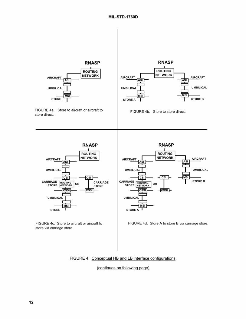
MIL-STD-1760D
12
RNASP
ROUTINGNETWORK
ASI
MSI
AIRCRAFT
UMBILICAL
STORE
FIGURE 4a. Store to aircraft or aircraft tostore direct.
AIRCRAFT
RNASP
ROUTINGNETWORK
ASI
MSI
UMBILICAL
STORE A
ASI
MSI
AIRCRAFT
UMBILICAL
STORE B
FIGURE 4b. Store to store direct.
AIRCRAFT
RNASP
ROUTINGNETWORK
ASI
CSI
UMBILICAL
CARRIAGESTORE
ASI
MSI
AIRCRAFT
UMBILICAL
STORE B
FIGURE 4d. Store A to store B via carriage store.
ROUTINGNETWORK
CSSI
MSI
UMBILICAL
OR
CSSI
STORE A
AIRCRAFT
RNASP
ROUTINGNETWORK
ASI
CSI
UMBILICAL
CARRIAGESTORE
FIGURE 4c. Store to aircraft or aircraft tostore via carriage store.
ROUTINGNETWORK
CSSI
MSI
UMBILICAL
OR
STORE
CARRIAGESTORE
CSI
CSSI
CSI
FIGURE 4. Conceptual HB and LB interface configurations.
(continues on following page)

MIL-STD-1760D
13
ASI
CSI
AIRCRAFT
UMBILICAL
CSI
CSSI
RNASP
ROUTINGNETWORK
ASI
MSI
AIRCRAFT
UMBILICAL
STORE A CARRIAGESTOREROUTING
NETWORK
CSS
UMBILICAL
OR
STORE B
FIGURE 4e. Store A to store B via carriage store.
ASI
CSI
AIRCRAFT
UMBILICAL
RNASP
ROUTINGNETWORK
ASI
CSI
AIRCRAFT
UMBILICAL
CARRIAGESTORE
ROUTINGNETWORK
UMBILICAL
OR
STORE B
FIGURE 4f. Store to store via carriage stores
ROUTINGNETWORK
CSSI
MSI
UMBILICAL
STORE A
CARRIAGESTORE OR
CSI
CSSI
CSI
CSSI
MSI MSI
CSSI
FIGURE 4. Conceptual HB and LB interface configurations. (Continued)
4.3.5 Primary interlock interface.The ASI interlock interface shall be available for the aircraft to monitor the electrically mated status of theprimary interface connector between stores and aircraft. The CSSI interlock interface shall be availablefor the carriage store to monitor the electrically mated status of the primary interface connector betweenstores and the carriage store.
CAUTION
The interlock interface shall not be used as the sole criterion for functionswhich could result in an unsafe condition if the interlock circuit fails open.
4.3.6 Address interface.The address interface shall be used to assign a unique MIL-STD-1553 remote terminal address to theconnected store. The address interface shall contain a set of six discretes (five binary weighted addressbit discretes A0 through A4 and one parity discrete) and one common address return. Stores maymonitor the address discretes to determine the mated status of the connector.
4.3.7 Primary structure ground. [Note 5.] A dedicated circuit shall be provided between the aircraft and store structure grounds. It shall provide anelectrical connection between aircraft and store structures to minimize shock hazards to personnel. Thestructure ground interface shall not be used as a signal return path or power return path except underfault conditions within the store
4.3.8 Primary power. [Note 6.] The aircraft shall supply and control all power to stores through the ASI. All ASIs shall provide two 28 Vdc sources, and either one 270 V dc source or one source of three-phase, four-wire, wye-connected, 400Hz, 115/200 V ac. The aircraft may have the capability to supply both 115 V ac and 270 V dc but shallnever apply both simultaneously. A dedicated power return shall be provided through the AEIS for each
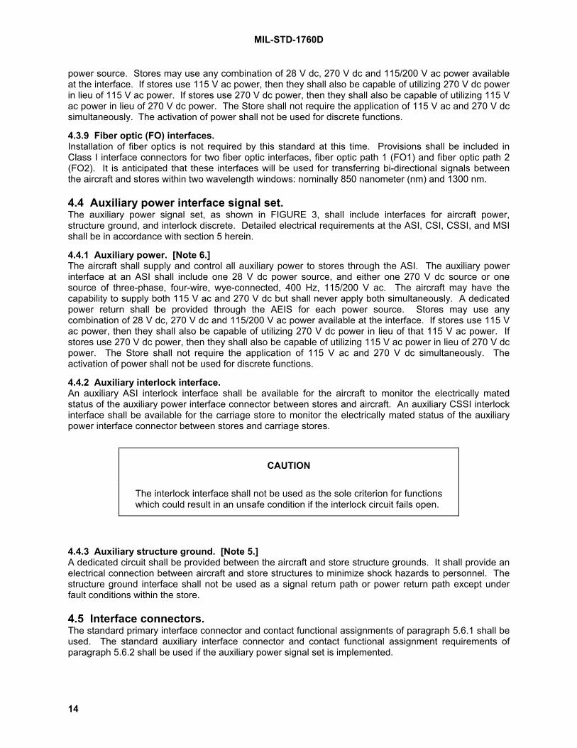
MIL-STD-1760D
14
power source. Stores may use any combination of 28 V dc, 270 V dc and 115/200 V ac power availableat the interface. If stores use 115 V ac power, then they shall also be capable of utilizing 270 V dc powerin lieu of 115 V ac power. If stores use 270 V dc power, then they shall also be capable of utilizing 115 Vac power in lieu of 270 V dc power. The Store shall not require the application of 115 V ac and 270 V dcsimultaneously. The activation of power shall not be used for discrete functions.
4.3.9 Fiber optic (FO) interfaces.Installation of fiber optics is not required by this standard at this time. Provisions shall be included inClass I interface connectors for two fiber optic interfaces, fiber optic path 1 (FO1) and fiber optic path 2(FO2). It is anticipated that these interfaces will be used for transferring bi-directional signals betweenthe aircraft and stores within two wavelength windows: nominally 850 nanometer (nm) and 1300 nm.
4.4 Auxiliary power interface signal set.The auxiliary power signal set, as shown in FIGURE 3, shall include interfaces for aircraft power,structure ground, and interlock discrete. Detailed electrical requirements at the ASI, CSI, CSSI, and MSIshall be in accordance with section 5 herein.
4.4.1 Auxiliary power. [Note 6.] The aircraft shall supply and control all auxiliary power to stores through the ASI. The auxiliary powerinterface at an ASI shall include one 28 V dc power source, and either one 270 V dc source or onesource of three-phase, four-wire, wye-connected, 400 Hz, 115/200 V ac. The aircraft may have thecapability to supply both 115 V ac and 270 V dc but shall never apply both simultaneously. A dedicatedpower return shall be provided through the AEIS for each power source. Stores may use anycombination of 28 V dc, 270 V dc and 115/200 V ac power available at the interface. If stores use 115 Vac power, then they shall also be capable of utilizing 270 V dc power in lieu of that 115 V ac power. Ifstores use 270 V dc power, then they shall also be capable of utilizing 115 V ac power in lieu of 270 V dcpower. The Store shall not require the application of 115 V ac and 270 V dc simultaneously. Theactivation of power shall not be used for discrete functions.
4.4.2 Auxiliary interlock interface.An auxiliary ASI interlock interface shall be available for the aircraft to monitor the electrically matedstatus of the auxiliary power interface connector between stores and aircraft. An auxiliary CSSI interlockinterface shall be available for the carriage store to monitor the electrically mated status of the auxiliarypower interface connector between stores and carriage stores.
CAUTION
The interlock interface shall not be used as the sole criterion for functionswhich could result in an unsafe condition if the interlock circuit fails open.
4.4.3 Auxiliary structure ground. [Note 5.] A dedicated circuit shall be provided between the aircraft and store structure grounds. It shall provide anelectrical connection between aircraft and store structures to minimize shock hazards to personnel. Thestructure ground interface shall not be used as a signal return path or power return path except underfault conditions within the store.
4.5 Interface connectors.The standard primary interface connector and contact functional assignments of paragraph 5.6.1 shall beused. The standard auxiliary interface connector and contact functional assignment requirements ofparagraph 5.6.2 shall be used if the auxiliary power signal set is implemented.

MIL-STD-1760D
15
5. DETAILED REQUIREMENTS
5.1 Aircraft requirements.The aircraft shall meet the following requirements at each ASI. Requirements shall be measurable at theASI (looking into the aircraft) except where indicated.
5.1.1 Aircraft HB interfaces.The aircraft shall provide HB interfaces at each ASI for (as a minimum) bi-directional simplex transfer oftype A and type B signals. The aircraft shall assign, control, and route HB signals to their properdestinations by means of a HB signal routing network. Each implemented routing network signal pathshall meet the following electrical requirements between the RNASP and ASI or between ASIs asapplicable. The following requirements cover all four HB interfaces, however, for interface classes II andIIA the requirements associated with HB2 and HB4 do not apply.
5.1.1.1 Minimum transfer capacity.The aircraft shall support the transfer of one type A signal or one type B signal on HB1, simultaneouslywith the transfer of type A signals on HB2, HB3, and HB4 through an ASI.
5.1.1.2 Type A signal path requirements.
5.1.1.2.1 Return loss.The input return loss of each signal path shall not be less than 20 dB over the frequency band 20 Hz to20 MHz when the output is terminated with the nominal impedance. The output return loss of each signalpath shall not be less than 20 dB over the frequency band 20 Hz to 20 MHz when the input is terminatedwith the nominal impedance.
5.1.1.2.2 Transient response.The transient response characteristics of each signal path shall meet the following requirements. Wheneach of the signals in FIGURE 5a, FIGURE 6a, FIGURE 7a, and FIGURE 8a is applied to the input, theoutput signal shall meet the requirements in FIGURE 5b, FIGURE 6b, and FIGURE 8b. For the responseenvelope in FIGURE 5b, V'1.0 is as defined in FIGURE 7b. For the response envelope in FIGURE 6b,V'1.3 is defined in FIGURE 8b.
5.1.1.2.3 Insertion gain.The signal path insertion gain between the input and output shall be 0 dB +0.5/-4.0 dB, where insertiongain = 20 log (V'1.3 / V). V and V'1.3 are defined in FIGURE 8a and FIGURE 8b respectively.
5.1.1.2.4 Representative pulse delay.The representative pulse delay of any signal path shall not exceed 2.0 microseconds and shall not varyby more than ±35 nanoseconds from its nominal value. The nominal value of the signal pathrepresentative pulse delay for the current routing path configuration shall be retained and made availablefor computing signal latency. When the signal in FIGURE 8a is applied to the input, the representativepulse delay is the time difference between the voltage V/2 being reached on the input signal rising edgeand the voltage V'1.3 /2 being reached on the output signal rising edge where V'1.3 is defined in FIGURE8b.
5.1.1.2.5 Equalization.The gain misequalization of any signal path shall not exceed the limits shown in FIGURE 9. The zero dBgain reference shall be the gain at 20 kHz. The maximum gain between 20 MHz and 200 MHz shall notexceed +3 dB with respect to the zero-dB gain reference.
5.1.1.2.6 Dynamic range.When a 1 kHz sine wave of peak-to-peak voltage 3.5 V is added to a dc voltage of ±0.5 V and thenapplied at the signal path input, the signal at the output shall not be compressed or clipped by more than6 percent.

MIL-STD-1760D
16
5.1.1.2.7 Signal path dc offset.The maximum dc voltage at the output of each signal path shall not exceed ±250 millivolts with the inputterminated.
5.1.1.2.8 Noise requirements.Noise at the type A signal path outputs shall meet the following requirements over the frequency band 20Hz to 20 MHz.
5.1.1.2.8.1 Random noise.Using the weighting function of FIGURE 10, the weighted random noise power at each signal path outputwith the input terminated shall not exceed -45 dBmRMS.
5.1.1.2.8.2 Periodic noise.The calculated periodic noise voltage at each signal path output with the input terminated shall notexceed 0.8 mVRMS for each valid state of the HB routing network. The noise voltage shall bedetermined by stimulating each HB and LB interface of the AEIS not associated with the signal path inturn by an in-band, maximum amplitude sinusoidal signal which produces the maximum weightedcrosstalk voltage at the signal path output. The weighting function is given in FIGURE 11. The frequencyof the stimulus signal may be different at each interface. The calculated periodic noise voltage shall bethe root sum of squares of the individual crosstalk voltages plus the unstimulated weighted periodic noisevoltage at the signal path output when all HB and LB interfaces are terminated.
5.1.1.2.8.3 Impulse noise.The peak-to-peak impulse noise voltage at the signal path output with the input terminated shall notexceed 40 mV.
5.1.1.2.8.4 Stimulated noise.No more than -26 dBm (HB1 and HB2) or -28 dBm (HB3 and HB4) of noise shall be added to the signalpath noise at the output when a 1.3 Vpp sinusoidal excitation signal of any frequency between 1 MHz and15 MHz is applied to the signal path input.
5.1.1.2.8.5 Common mode noise.Using the weighting function of FIGURE 12, the RMS common mode noise voltage at the output of eachsignal path shall not exceed 200 mV with respect to the output structure ground when the input isterminated and the input signal return is connected to the input structure ground.
5.1.1.3 Type B signal path requirements.(None specified at this time)
5.1.1.4 Ground reference.When a HB interface in an ASI is sending a type A or type B signal, the signal return shall be connectedto aircraft structure ground as shown in FIGURE 13a. When a HB interface in an ASI is receiving a typeA signal, the signal return shall be isolated from aircraft structure ground as shown in FIGURE 13b.When a HB interface in an ASI is receiving a type B signal, the signal return shall be connected to aircraftstructure ground as shown in FIGURE 13c.

MIL-STD-1760D
17
-T
v(t) = V cos2 [ πt 2T
where T = 25 nanoseconds, V = + 1.0 volt
v(t) = 0 elsewhere
V
v(t)
V/2 T
0t
+T
for -T < t < +T]
FIGURE 5a. Cosine-squared T signal. [Note 7.]
Waveform shall not be belowthis line between -100 ns & +100 ns
Peak value shall occurbetween -25 ns & +25 ns, andshall not be below this line.
Waveform shall not be abovethis line for times between25 ns & 100 ns.
Waveform shall not be above thisline between -100 ns & -25 ns.
-5%V'1.0-10%V'1.0
+5%V'1.0
+10%V'1.0
+18%V'1.0
-18%V'1.0
-100 ns -50 ns -25 ns 0 +25 ns +50 ns +100 ns
The time origin (0 ns) for the envelope is arbitrary with respect toboth the stimulus and response waveformsFor sampled systems, the response envelope shall apply to anyalignment of the input signal with respect to the sample clock.
+73%V'1.0 minimum
v(t)
NOTE 2:
NOTE 1:
FIGURE 5b. Allowed response envelope for cosine-squared T signal. [Note 8.]
FIGURE 5. Cosine-squared T signal requirements.
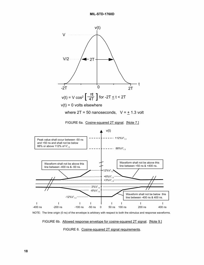
MIL-STD-1760D
18
-2T
v(t) = V cos2 [ ] πt4T for -2T < t < 2T
v(t) = 0 volts elsewhere
V
v(t)
V/2 2T
0t
2T
where 2T = 50 nanoseconds, V = + 1.3 volt
FIGURE 6a. Cosine-squared 2T signal. [Note 7.]
Waveform shall not be below thisline between -400 ns & 400 ns.
Peak value shall occur between -50 nsand +50 ns and shall not be below88% or above 112% of V'1.3
Waveform shall not be above thisline between +50 ns & +400 ns.
Waveform shall not be above thisline between -400 ns & -50 ns.
-3%V'1.3
-6%V'1.3
+3%V'1.3
+6%V'1.3
+12%V'1.3
-12%V’1.3
-200 ns -100 ns -50 ns 0 50 ns 100 ns 200 ns
NOTE: The time origin (0 ns) of the envelope is arbitrary with respect to both the stimulus and response waveforms.
112%V'1.3
88%V'1.3
v(t)
400 ns-400 ns
FIGURE 6b. Allowed response envelope for cosine-squared 2T signal. [Note 9.]
FIGURE 6. Cosine-squared 2T signal requirements.

MIL-STD-1760D
19
v(t) = g(t) * E [ ] t25µs
where: * denotes convolution
= 0 volts elsewhereg(t)
E [ ] t25µs
= 1 for -12.5 µs < t < 12.5 µs= 0 elsewhere
where 2T = 50 ns, V = + 1.0 volt
25 µs
2T 2T
V
0
V/2
=2TV
cos 2πt4T[ ] for -2T ≤ t < 2T
FIGURE 7a. 2T Bar signal (± 1.0V).
2T Bar Response(Typical) V'1.0 (see note 1)
V'1.0 /2 V'1.0 /2
t
NOTE 1: V'1.0 is the value measured at the midpoint between the V'1.0 /2 points.
v(t)
FIGURE 7b. Allowed response envelope for 2T Bar signal (referenced to ±1.0V).
FIGURE 7. 2T Bar signal requirements (1.0V).

MIL-STD-1760D
20
25 µs
v(t) = g(t) * E [ ] t 25µs
(where: * denotes convolution)
{ = 0 volts elsewhereg(t)
E [ ] t 25µs
= 1 for -12.5 µs < t < 12.5 µs= 0 elsewhere
where 2T = 50 nanoseconds, V = + 1.3 volts
v(t)
2T 2T
V
0
V/2
=2TV
cos 2πt4T[ ] for -2T ≤ t < 2T
FIGURE 8a. 2T Bar signal (± 1.3V).
1.0 µs 1.0 µs
2T Bar Response(Typical)
V'1.3 (see note 2)1.015 V'1.3
0.985V'1.3
V'1.3 /2
t
NOTE 1: The exact shape of the 2T Bar Response waveform is not important.The only requirement is that it be within the shaded box.
NOTE 2: V'1.3 is the value measured at the midpoint between the V'1.3 /2 points.
v(t)
FIGURE 8b. Allowed response envelope for 2T Bar signal (referenced to ±1.3V).
FIGURE 8. 2T Bar signal requirements (1.3V).
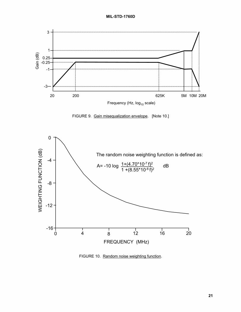
MIL-STD-1760D
21
Frequency (Hz, log10 scale)
20
Gai
n (d
B)
-3
-1
-0.250.25
1
3
625K 5M 10M 20M200
FIGURE 9. Gain misequalization envelope. [Note 10.]
12 16 20840-16
-12
-8
-4
0
The random noise weighting function is defined as:
1+(4.70*10-7 f)2
1 +(8.55*10-8 f)2
WEI
GH
TIN
G F
UN
CTI
ON
(dB)
FREQUENCY (MHz)
A= -10 log dB
FIGURE 10. Random noise weighting function.

MIL-STD-1760D
22
0
-5
-10
-15
-20
-25
Wei
ghtin
g fu
nctio
n (d
B)
Frequency (Hz)100 1k 10k 100k 1M 10M 20M
A = 10 log
1 + f 1150 Hz
2
1 + f 500 Hz
21 + f
4 MHz
21 + f
20 MHz
2dB
The periodic noise weighting function is defined as:
FIGURE 11. Periodic noise weighting function.
0
-7-10
-20
-26
-30DC 200100 1k 10k 30k 100k 1M 10M 20M
FREQUENCY (Hz)
WEI
GH
TIN
G F
UN
CTI
ON
(dB
)
FIGURE 12. Common mode noise weighting function.

MIL-STD-1760D
23
Signal return (shield) connection
Signalconnection
Equivalentvoltagesource
Equivalent source impedance
FIGURE 13a. Equivalent circuit of HB interface when sending a Type A or Type B signal.
Signal connection
Signal return (Shield) connection
Equivalentsinkimpedance
FIGURE 13b. Equivalent circuit of HB interface when receiving a Type A signal.
Signal connection
Signal return (Shield) connection
Equivalentsinkimpedance
FIGURE 13c. Equivalent circuit of HB interface when receiving a Type B signal.
FIGURE 13. Equivalent circuits of HB interfaces.
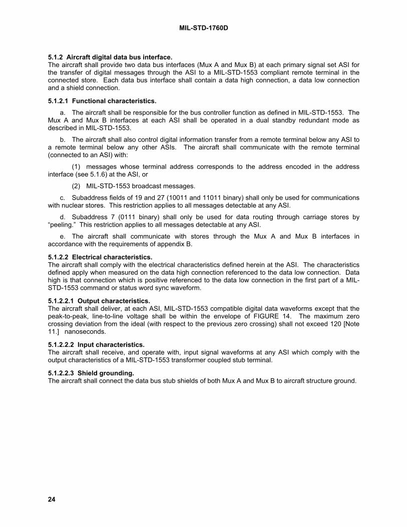
MIL-STD-1760D
24
5.1.2 Aircraft digital data bus interface.The aircraft shall provide two data bus interfaces (Mux A and Mux B) at each primary signal set ASI forthe transfer of digital messages through the ASI to a MIL-STD-1553 compliant remote terminal in theconnected store. Each data bus interface shall contain a data high connection, a data low connectionand a shield connection.
5.1.2.1 Functional characteristics.a. The aircraft shall be responsible for the bus controller function as defined in MIL-STD-1553. The
Mux A and Mux B interfaces at each ASI shall be operated in a dual standby redundant mode asdescribed in MIL-STD-1553.
b. The aircraft shall also control digital information transfer from a remote terminal below any ASI toa remote terminal below any other ASIs. The aircraft shall communicate with the remote terminal(connected to an ASI) with:
(1) messages whose terminal address corresponds to the address encoded in the addressinterface (see 5.1.6) at the ASI, or
(2) MIL-STD-1553 broadcast messages.
c. Subaddress fields of 19 and 27 (10011 and 11011 binary) shall only be used for communicationswith nuclear stores. This restriction applies to all messages detectable at any ASI.
d. Subaddress 7 (0111 binary) shall only be used for data routing through carriage stores by“peeling.” This restriction applies to all messages detectable at any ASI.
e. The aircraft shall communicate with stores through the Mux A and Mux B interfaces inaccordance with the requirements of appendix B.
5.1.2.2 Electrical characteristics.The aircraft shall comply with the electrical characteristics defined herein at the ASI. The characteristicsdefined apply when measured on the data high connection referenced to the data low connection. Datahigh is that connection which is positive referenced to the data low connection in the first part of a MIL-STD-1553 command or status word sync waveform.
5.1.2.2.1 Output characteristics.The aircraft shall deliver, at each ASI, MIL-STD-1553 compatible digital data waveforms except that thepeak-to-peak, line-to-line voltage shall be within the envelope of FIGURE 14. The maximum zerocrossing deviation from the ideal (with respect to the previous zero crossing) shall not exceed 120 [Note11.] nanoseconds.
5.1.2.2.2 Input characteristics.The aircraft shall receive, and operate with, input signal waveforms at any ASI which comply with theoutput characteristics of a MIL-STD-1553 transformer coupled stub terminal.
5.1.2.2.3 Shield grounding.The aircraft shall connect the data bus stub shields of both Mux A and Mux B to aircraft structure ground.
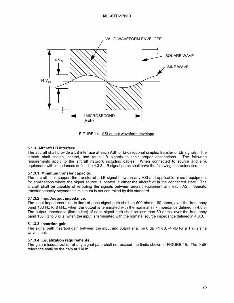
MIL-STD-1760D
25
1MICROSECOND(REF)
1.4 Vpp
14 Vpp
VALID WAVEFORM ENVELOPE
SQUARE WAVE
SINE WAVE
FIGURE 14. ASI output waveform envelope.
5.1.3 Aircraft LB interface.The aircraft shall provide a LB interface at each ASI for bi-directional simplex transfer of LB signals. Theaircraft shall assign, control, and route LB signals to their proper destinations. The followingrequirements apply to the aircraft network including cables. When connected to source and sinkequipment with impedances defined in 4.3.3, LB signal paths shall have the following characteristics.
5.1.3.1 Minimum transfer capacity.The aircraft shall support the transfer of a LB signal between any ASI and applicable aircraft equipmentfor applications where the signal source is located in either the aircraft or in the connected store. Theaircraft shall be capable of rerouting the signals between aircraft equipment and each ASI. Specifictransfer capacity beyond this minimum is not controlled by this standard.
5.1.3.2 Input/output impedance.The input impedance (line-to-line) of each signal path shall be 600 ohms ±60 ohms, over the frequencyband 150 Hz to 8 kHz, when the output is terminated with the nominal sink impedance defined in 4.3.3.The output impedance (line-to-line) of each signal path shall be less than 60 ohms, over the frequencyband 150 Hz to 8 kHz, when the input is terminated with the nominal source impedance defined in 4.3.3.
5.1.3.3 Insertion gain.The signal path insertion gain between the input and output shall be 0 dB +1 dB, -4 dB for a 1 kHz sinewave input.
5.1.3.4 Equalization requirements.The gain misequalization of any signal path shall not exceed the limits shown in FIGURE 15. The 0 dBreference shall be the gain at 1 kHz.

MIL-STD-1760D
26
Frequency (Hz)8k3.4k1k300150
Gai
n (d
B)
0
-2
+1
FIGURE 15. Gain misequalization envelope (aircraft, LB).
5.1.3.5 Signal path dc offset.The maximum dc voltage at the output of each signal path shall not exceed ±1 V line-to-line and ±1 Vline-to-ground with the input terminated.
5.1.3.6 Noise.The signal path noise shall meet the following requirements over the frequency band 150 Hz to 8 kHzexcept where otherwise specified.
5.1.3.6.1 Periodic and random noise.The calculated periodic and random noise voltage at each signal path output with the input terminatedshall not exceed 12.5 mVRMS for each valid state of the LB routing network. The noise voltage shall bedetermined by stimulating each LB and HB interface of the AEIS not associated with the signal path inturn by an in-band (150 Hz to 8 kHz), maximum amplitude sinusoidal signal which produces themaximum crosstalk voltage at the signal path output. The frequency of the stimulus signal may bedifferent at each interface. The calculated noise voltage shall be the root sum of squares of the individualcrosstalk voltages plus the unstimulated periodic and random noise voltage at the signal path outputwhen all LB and HB interfaces are terminated.
5.1.3.6.2 Impulse noise.With the input of the signal path terminated, there shall be (to one standard deviation) no more than twooccurrences of impulse noise exceeding 20 mV peak over a three minute period. The impulse noisevoltage shall apply when band-limited to 8 kHz low pass.
5.1.3.6.3 Stimulated noise.For any frequency between 300 Hz and 3.4 kHz, application of a 12 Vpp sinusoidal excitation signal tothe signal path input shall not add more than 80 mV RMS of noise to the output over the frequency range150 Hz to 8 kHz.
5.1.3.6.4 Common mode noise.The peak common mode noise voltage at the output of each signal path shall not exceed ±1 V when theinput is terminated and the input shield is at the same potential as the local structure ground. Thisrequirement shall apply over the band 150 Hz to 50 kHz.
5.1.3.7 Ground reference.When the LB interface in an ASI is sending a signal, the inverting and non-inverting signals shall bereferenced to ground as shown in FIGURE 16a. When the LB interface in an ASI is receiving a signal,

MIL-STD-1760D
27
the signal shall be represented by the difference between the non-inverting signal and the inverting signalas shown in FIGURE 16b. The shield shall be connected to ground.
V1
V2
R1
R2
non-invertingsignal connection
inverting signal connection
shield
Notes: 1. V1-V2 is theThevenin equivalent voltagesource (balanced withrespect to ground).
2. R1+R2 is theThevenin equivalent sourceimpedance.
FIGURE 16a. Equivalent circuit of ASI or MSI when sending a LB signal.
shield
non-invertingsignal connection
inverting signal connection
FIGURE 16b. Equivalent circuit of ASI or MSI when receiving a LB signal.
FIGURE 16. Equivalent circuits for LB interfaces.
5.1.4 Aircraft release consent interface.The aircraft shall provide a release consent interface at each primary signal set ASI for transferring anenable/inhibit signal to the connected store. Release consent, when in the enabled state, shall indicateaircraft consent for stores to perform safety-critical functions (such as store release from a carriage store,missile launch from a rail launcher or rocket firing from a dispenser) when commanded over the data businterface (see 4.3.4). The aircraft shall require positive crew action to generate the enabled state of therelease consent signal. When in the inhibited state, the release consent interface at an ASI shall beelectrically isolated from the release consent interface at all other ASIs. The isolation shall be 100kilohms minimum at dc.
5.1.4.1 Voltage level.The voltage level measured between the release consent connection and 28 V dc power 2 returnconnection at the ASI shall be:
a. Steady State Conditions
(1) Enable: Minimum voltage of 19.0 V dc
Maximum voltage, in accordance with MIL-STD-704 for 28 V dc
(2) Inhibit: 1.50 V dc (maximum)
b. Voltage transients shall comply with MIL-STD-704 limits for 28 V dc applications.

MIL-STD-1760D
28
5.1.4.2 Current level.Mission and carriage stores may require 100 milliamperes steady state through the ASI during the enablestate and the aircraft shall be able to supply that current. The aircraft is not, however, required to supplyany current in excess of 100 milliamperes. The aircraft shall comply with the requirements herein forstore imposed load currents of 5.0 milliamperes minimum through the ASI.
5.1.4.3 Stabilization time.With any resistive load between 320 ohms and 3.8 kilohms connected between release consent and28 V dc power 2 return, the voltage at the ASI shall reach steady state levels (see 5.1.4.1.a) within3 milliseconds during transition between enable and inhibit states.
5.1.4.4 Enable lead time.If release consent is required by a store, the release consent signal shall attain the enable state at least20 milliseconds prior to transferring the safety critical command over the data bus interface or prior to thefiring signal to the parent S&RE, as applicable.
5.1.4.5 Inhibit delay.If release consent at an ASI has been enabled, the aircraft shall operate under the assumption that thestore(s) connected to that ASI may remain in an enable state for up to 20 milliseconds after the releaseconsent signal has been returned to the inhibit state.
5.1.4.6 Ground reference.The 28 V dc power 2 return connection shall be the ground reference for release consent.
5.1.5 Aircraft interlock interface.The aircraft shall provide an interlock interface at each primary signal set ASI and auxiliary power signalset ASI for monitoring the mated status of the associated connectors. The interlock interface at eachprimary and auxiliary ASI consists of an interlock connection and an interlock return connection. If theaircraft monitors the interlock interface, then the aircraft shall comply with the following requirements.These requirements apply to the interlock connection referenced to the interlock return connection.
a. Open circuit voltage
(1) Minimum voltage of 4.0 V dc
(2) Maximum voltage, in accordance with MIL-STD-704 for 28 V dc
(3) Voltage transients shall not exceed the upper limit defined in MIL-STD-704 for 28 V dc
b. Excitation current
(1) Minimum current of 5.0 milliamperes
(2) Maximum current of 100 milliamperes
c. Impedance detection threshold. An interface disconnected condition shall be detected for anyimpedance level of 100 kilohms or greater. An interface connected condition shall be detected for anyimpedance level of 2.0 ohms or less. These impedance values apply over the frequency range of dc to 4kHz.
5.1.6 Aircraft address interface.The aircraft shall provide an address interface at each primary signal set ASI for assigning a data busaddress to the MIL-STD-1553 remote terminal in the store mated to the ASI. Each address interfaceshall include five binary encoded address bit connections (A0, A1, A2, A3, and A4), one address parityconnection and one common address return connection. The aircraft shall use this interface only forassigning an address to the remote terminal associated with the directly connected carriage store ormission store.
5.1.6.1 Address assignment.The aircraft shall supply a logic 0 state or logic 1 state on each of the five binary weighted address bitconnections at each ASI. The remote terminal address assigned to an ASI shall be defined as follows:

MIL-STD-1760D
29
a. Remote terminal address = (A4) x 2
4 + (A
3) x 2
3 + (A
2) x 2
2 + (A
1) x 2
1 + (A
0) x 2
0
b. The aircraft shall supply a logic 0 state or logic 1 state on the address parity connection such thatan odd number of logic 1 states exist on the five address bit connections plus the address parityconnection.
The aircraft shall not modify the address assigned to an ASI whenever any power (see 5.1.8, 5.1.9, and5.1.10) is applied to that ASI.
5.1.6.2 Address signal.The aircraft shall comply with the requirements herein when signals with the following characteristics areapplied to the address interface at the ASI by the connected store. The characteristics defined apply tothe address bit and parity connections referenced to the address return connection.
a. Open circuit (logic 1) voltage
(1) Minimum voltage of 3.5 V dc
(2) Maximum voltage of 31.5 V dc
(3) Rise and fall times of applied voltage less than 10 milliseconds
b. Logic 0 current
(1) Minimum current of 5.0 milliamperes dc
(2) Maximum current of 100 milliamperes dc through each address bit and parity connection
(3) Maximum current of 600 milliamperes dc through the address return connection
(4) Rise and fall times of applied current less than 10 milliseconds
5.1.6.3 Logic thresholds.The aircraft shall provide the following logic states under the voltage and current conditions of 5.1.6.2:
a. Logic 1 state characteristics. The aircraft shall maintain sufficient open circuit conditions betweeneach logic 1 set address bit (or parity) connection and the return connection such that when the voltagesof 5.1.6.2 are applied across the connections, the current flow shall not exceed 300 microamperes.
b. Logic 0 state characteristics. The aircraft shall limit the voltage drop between each logic 0 setaddress bit (or parity) connection and return connection at the ASI to 1.0 volts maximum when the currentlevels specified in 5.1.6.2 are applied. This maximum voltage drop applies when logic 0 states exist atany or all address bit and parity connections.
5.1.6.4 Response characteristics.The aircraft shall produce valid address characteristics at the ASI within 10 milliseconds of excitationsignal application from the store. The aircraft shall not require continuous application of the excitationsignal.
5.1.6.5 Address isolation.The aircraft shall electrically isolate all address connections (including address return) at each ASI fromthe address connections at all other ASIs, from power returns and from aircraft structure. The isolationshall be 100 kilohms minimum over the frequency range of dc to 4 kHz.
5.1.7 Aircraft structure ground. [Note 12.] The aircraft shall provide a conductive path from the ASI structure ground interface to aircraft structure,capable of carrying the overcurrent level defined in FIGURE 17 for the primary ASI and FIGURE 18 forthe auxiliary ASI. The structure ground interface shall not be used as a signal return path or power returnpath except under fault conditions within the store. The voltage drop between the ASI structure groundinterface and the aircraft ground shall not exceed 0.2 volts when conducting 10 amperes (continuous) forthe primary ASI and 30 amperes (continuous) for the auxiliary ASI.

MIL-STD-1760D
30
5.1.8 Aircraft 28 V dc power interface.The aircraft shall provide a set of 28 V dc power interfaces at each ASI. The primary signal set ASI shallcontain 28 V dc power 1 (and power 1 return) connections and 28 V dc power 2 (and power 2 return)connections. The auxiliary power signal set ASI shall contain 28 V dc power (and power return)connections.
5.1.8.1 Independent control.The aircraft shall be capable of sourcing and independently controlling each 28 V dc power interfacethrough each primary signal set ASI and through each auxiliary power signal set ASI.
5.1.8.2 Voltage level. [Note 13.] The voltages at the ASI between each 28 V dc power connection and the associated power returnconnection shall comply with the 28 V dc normal and abnormal operation characteristics for utilizationequipment defined in MIL-STD-704 with the following addition: the normal steady state lower voltage limitat the ASI shall be 22.0 V dc at any current up to full rated load (10 A for primary, 30 A for auxiliary).Voltage transients at the ASI shall comply with MIL-STD-704.
5.1.8.3 Current capacity.
5.1.8.3.1 Primary signal set.The aircraft shall be capable of sourcing the maximum load current levels of FIGURE 17a through the 28V dc power 1 interface and the maximum load current levels of FIGURE 17a through the 28 V dc power 2interface of the ASI. The aircraft shall be capable of sourcing a total of 20 amperes, continuously throughthe combination of 28 V dc power 1 and 28 V dc power 2 interfaces of the ASI.
5.1.8.3.2 Auxiliary power signal set.For interface classes IA and IIA, the aircraft shall be capable of sourcing the maximum load current levelsof FIGURE 18a through the 28 V dc power interface of the auxiliary ASI.
5.1.8.3.3 Simultaneous current.The total 28 V dc current available simultaneously from all ASIs is not controlled by this standard. Thetotal 28 V dc continuous current provided simultaneously through both the primary and auxiliaryinterfaces at any class IA or IIA ASI need not exceed 30 amperes.
5.1.8.4 Overcurrent protection.The aircraft shall ensure that the current flow through any 28 V dc power connection does not exceed themaximum overcurrent limits of FIGURE 17 and FIGURE 18 for the primary and auxiliary ASIs,respectively. The aircraft may achieve this current limit operation by the deactivation of the appropriatepower interface and any other power interface at the associated ASI.
5.1.8.5 Off-state leakage current.The off-state leakage current from each 28 V dc power ASI output to its respective return shall notexceed 1.0 milliampere dc with all load impedances. [Note 14.] The off-state leakage current fromauxiliary 28 V dc power ASI output to the auxiliary power return shall not exceed 2.50 milliamperes dcwith all load impedances.

MIL-STD-1760D
31
10
100
0 0.1 1 10 100 1000
CURRENT DURATION (SEC)
CU
RR
ENT
(A)
65
1.6
24
Circuit Protection“Never Trip” Zone
Circuit Protection“May Trip” Zone
Circuit Protection“Always Trip” Zone30
MAXIMUMOVERCURRENT
MAXIMUM LOAD CURRENT
for 0.1 < t < 300 sec
10285.085.63)683.0(0.65
+
−=t
for 1.6 < t < 300 sec
240.73
25.075.62)57.4( +
−=t
FIGURE 17a. Primary interface current level for 28 V dc and 115/200 V ac power.
10
100
0 0.1 1 10 100 1000
CURRENT DURATION (SEC)
CU
RR
ENT
(A)
Circuit protection "never trip" zone
Circuit protection "may trip" zone
Circuit protection "always trip" zone
50
2430
1.6
0.04
for 0.04 < t < 10 sec
100.8
47.04.71)88.0( +
−=t
for 1.6 < t < 300 sec
240.73
25.075.62)57.4( +
−=t
MAXIMUMLOAD
CURRENTMAXIMUM OVERCURRENT
FIGURE 17b. Primary interface current level for 270 V dc power. [Note 16.]
FIGURE 17. Primary interface current level. [Note 15.]

MIL-STD-1760D
32
10
100
1000
0 0.1 1 10 100 1000CURRENT DURATION (sec)
CU
RR
ENT
(A) 240
30
Circuit protection"always trip" zone
Circuit protection"may trip" zone
Circuit protection"never trip" zone
58
1.9
for 0.1 < t < 300 sec
300.65
362.0108.85)23.2( +
−=
t
for 1.9 < t < 300 sec
580.85
216.064.98)02.12( +
−=t
MAXIMUM LOAD CURRENT
MAXIMUM OVERCURRENT
FIGURE 18a. Auxiliary interface current level for 28 V dc and 115/200 V ac power.
10
100
1000
0 0.1 1 10 100 1000CURRENT DURATION (sec)
CU
RR
ENT
(A)
120
30
Circuit protection"always trip" zone
Circuit protection"may trip" zone
Circuit protection"never trip" zone
45
0.06
1.6
for 1.6 < t < 300 sec
451.0
0135.04.36)19.33( +
−=t
for 0.06 < t < 10 sec
1.290.85
13.04.71)23.2( +
−=t
MAXIMUM LOAD CURRENT
MAXIMUM OVERCURRENT
FIGURE 18b. Auxiliary interface current level for 270 V dc power. [Note 16.]
FIGURE 18. Auxiliary interface current level. [Note 15.]
NOTE: The curves of FIGURE 17 and FIGURE 18 define a locus of discrete current-time points (such as13 amperes for 10 seconds duration) and are not intended to represent a continuous profile of currentversus time.

MIL-STD-1760D
33
5.1.8.6 Stabilization time.When tested with a resistive load connected to the ASI, the voltage at the ASI shall reach steady statelevels (see 5.1.8.2) within 3.0 milliseconds of power turn-on and turn-off (see FIGURE 19) at any currentup to full rated load (10 A for primary, 30 A for auxiliary).
POWER ON
VOLTAGE
SPECIFIEDINTERFACEVOLTAGELEVEL
VMIN
POWER OFF
0.1 VMIN
STABILIZATION TIME
POWEROFF
TIME
FIGURE 19. Stabilization time.
5.1.8.7 Ground reference.The 28 V dc power return connections at the primary and auxiliary ASIs shall be the reference for eachassociated 28 V dc power connection.
5.1.8.8 Power application.The aircraft shall only energize 28 V dc power 2 and auxiliary 28 V dc when the aircraft has determinedthat it is safe to do so. The aircraft operation shall consider that some stores may use 28 V dc power 2 orauxiliary 28 V dc for powering safety critical functions such that store safety may be degraded withactivation of these power interfaces. The aircraft may energize 28 V dc power 1 at any time under theassumption that all store functions so powered are either not safety critical or that multiple safetyinterlocks exist within the store such that store safety is not significantly degraded by activation of 28 V dcpower 1.
5.1.9 Aircraft 115/200 V ac power interface.The aircraft shall provide a set of three-phase, four-wire, wye-connected, 115/200 V ac power interfacesat each ASI (see 4.3.8 and 4.4.1). The primary signal set ASI shall contain 115 V ac phase A, phase B,phase C, and neutral connections. The auxiliary power signal set ASI shall contain 115 V ac phase A,phase B, phase C, and neutral connections.
5.1.9.1 Independent control and dead facing.The aircraft shall be capable of sourcing and independently controlling the 115/200 V ac power interfacethrough each primary interface signal set ASI and through each auxiliary power signal set ASI. Theaircraft shall ensure that no ac power is applied to the ASI until an indication is available that the store ismated, such as the interlock circuit is complete. The aircraft shall also ensure that ac power is removedfrom the ASI prior to store separation or connector disconnect.

MIL-STD-1760D
34
5.1.9.2 Voltage level. [Note 13.] The voltage at the ASI between each 115 V ac phase connection and the associated 115 V ac neutralconnection shall comply with the 115 V ac normal and abnormal operation characteristics for utilizationequipment defined in MIL-STD-704 with the following addition: the normal steady state lower voltage limitat the ASI shall be 108.0 V RMS at any current up to full rated load (10 A for primary, 30 A for auxiliary).Voltage transients at the ASI shall comply with MIL-STD-704.
5.1.9.3 Current capacity.
5.1.9.3.1 Primary signal set.The aircraft shall be capable of sourcing the maximum load current levels of FIGURE 17 simultaneouslythrough each of the three 115 V ac phases of the primary signal set ASI.
5.1.9.3.2 Auxiliary power signal set.For interface classes IA and IIA, the aircraft shall be capable of sourcing the maximum load current levelsof FIGURE 18 simultaneously through each of the three 115 V ac power phases of the auxiliary ASI.
5.1.9.3.3 Simultaneous current.The total 115 V ac current available simultaneously from all ASIs is not controlled by this standard. Thetotal 115 V ac continuous current provided simultaneously through both primary and auxiliary interfacesat any class IA and IIA ASI need not exceed 30 amperes per phase.
5.1.9.4 Overcurrent protection.The aircraft shall ensure that the current flow through any 115 V ac power phase connection does notexceed the maximum overcurrent limits of FIGURE 17a and FIGURE 18a for the primary and auxiliaryASIs, respectively. The aircraft may achieve this current limit operation by the deactivation of theappropriate power interface and any other power interface at the associated ASI.
5.1.9.5 Off-state leakage current.The off-state leakage current from each 115 V ac phase output to the associated 115 V ac neutral shallbe less than 2.0 milliamperes for the primary signal set ASI and shall be less than 5.0 milliamperes for theauxiliary power signal set ASI with all load impedances. [Note 14.]
5.1.9.6 Stabilization time.When tested with a resistive load connected to the ASI, the voltage at the ASI shall reach steady statelevels within 3.0 milliseconds of power turn-on and turn-off (see FIGURE 19) at any current up to fullrated load (10 A for primary, 30 A for auxiliary [Note 14.] ).
5.1.9.7 Phase rotation.The three 115 V ac, 400 Hz, power phases at the ASI shall comply with the phase sequence and voltagephase difference requirements of MIL-STD-704. The power phase assigned to contact location A in theauxiliary ASI connector shall be the identical phase as assigned to contact location P in the primary ASIconnector at the same ASI location.
5.1.9.8 Load power factor.The electrical characteristics at the ASI shall comply with the requirements herein when loads with apower factor within the limits of FIGURE 20 are applied to the ASI.
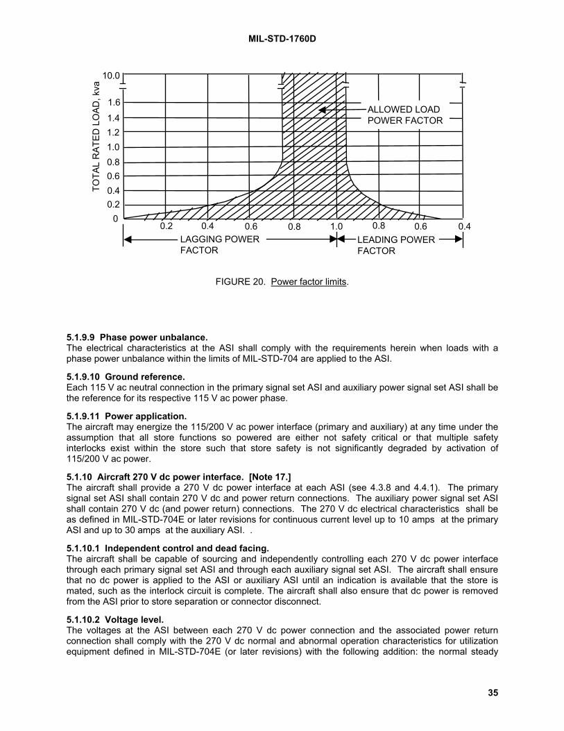
MIL-STD-1760D
35
TOTA
L R
ATED
LO
AD, k
va
10.0
1.6
1.41.21.00.80.60.40.2
00.2 0.4 0.6 0.8 1.0 0.8 0.6 0.4
ALLOWED LOADPOWER FACTOR
LAGGING POWERFACTOR
LEADING POWERFACTOR
FIGURE 20. Power factor limits.
5.1.9.9 Phase power unbalance.The electrical characteristics at the ASI shall comply with the requirements herein when loads with aphase power unbalance within the limits of MIL-STD-704 are applied to the ASI.
5.1.9.10 Ground reference.Each 115 V ac neutral connection in the primary signal set ASI and auxiliary power signal set ASI shall bethe reference for its respective 115 V ac power phase.
5.1.9.11 Power application.The aircraft may energize the 115/200 V ac power interface (primary and auxiliary) at any time under theassumption that all store functions so powered are either not safety critical or that multiple safetyinterlocks exist within the store such that store safety is not significantly degraded by activation of115/200 V ac power.
5.1.10 Aircraft 270 V dc power interface. [Note 17.] The aircraft shall provide a 270 V dc power interface at each ASI (see 4.3.8 and 4.4.1). The primarysignal set ASI shall contain 270 V dc and power return connections. The auxiliary power signal set ASIshall contain 270 V dc (and power return) connections. The 270 V dc electrical characteristics shall beas defined in MIL-STD-704E or later revisions for continuous current level up to 10 amps at the primaryASI and up to 30 amps at the auxiliary ASI. .
5.1.10.1 Independent control and dead facing.The aircraft shall be capable of sourcing and independently controlling each 270 V dc power interfacethrough each primary signal set ASI and through each auxiliary signal set ASI. The aircraft shall ensurethat no dc power is applied to the ASI or auxiliary ASI until an indication is available that the store ismated, such as the interlock circuit is complete. The aircraft shall also ensure that dc power is removedfrom the ASI prior to store separation or connector disconnect.
5.1.10.2 Voltage level.The voltages at the ASI between each 270 V dc power connection and the associated power returnconnection shall comply with the 270 V dc normal and abnormal operation characteristics for utilizationequipment defined in MIL-STD-704E (or later revisions) with the following addition: the normal steady
MIL-STD-1760D
36
state lower voltage limit at the ASI shall be 250.0 V dc at any current up to full rated load (10 A forprimary, 30 A for auxiliary). Voltage transients at the ASI shall comply with MIL-STD-704E (or laterrevisions).
5.1.10.3 Current capacity.
5.1.10.3.1 Primary signal set.The aircraft shall be capable of sourcing the maximum load current levels of FIGURE 17b through the270 V dc power interface of the ASI.
5.1.10.3.2 Auxiliary power signal set.For interface class IA and IIA, the aircraft shall be capable of sourcing the maximum load current levels ofFIGURE 18b through the 270 V dc power interface of the auxiliary ASI.
5.1.10.3.3 Simultaneous current.The total 270 V dc current available simultaneously from all ASIs is not controlled by this standard. Thetotal 270 V dc continuous current provided simultaneously through both the primary and auxiliaryinterfaces at any class IA and IIA ASI need not exceed 30 amperes.
5.1.10.4 Overcurrent protection.The aircraft shall ensure that the current flow through any 270 V dc power connection does not exceedthe maximum overcurrent limits of FIGURE 17b and FIGURE 18b for the primary and auxiliary ASIs,respectively. The aircraft may achieve this current limit operation by the deactivation of the appropriatepower interface and any other power interface at the associated ASI.
5.1.10.5 Off-state leakage current.The off-state leakage current from each 270 V dc power output to its respective return shall not exceed2.0 milliampere dc with all load impedances. The off-state leakage current from the auxiliary 270 V dcpower output to the auxiliary power return shall not exceed 5.0 milliamperes dc with all load impedances.
5.1.10.6 Stabilization time.When tested with a resistive load connected to the ASI, the voltage at the ASI shall reach steady statelevels within 3.0 milliseconds of power turn-on and turn-off (see FIGURE 19) at any current up to fullrated load (10 A for primary, 30 A for auxiliary).
5.1.10.7 Ground reference.The 270 V dc power return connections at the primary and auxiliary ASIs shall be the reference for eachassociated 270 V dc power connection.
5.1.10.8 Power application.The aircraft may energize 270 V dc power (primary and auxiliary) at any time under the assumption thatall store functions so powered are either not safety critical or that multiple safety interlocks exist within thestore such that store safety is not significantly degraded by activation of 270 V dc power.
5.1.11 Aircraft fiber optic interface.The two fiber optic interfaces are growth provisions for future applications. The fiber optic interfaces shallnot be activated at an ASI until characteristics and performance details are added to this standard. Allclass I interface connectors at all ASIs shall include two 16 AWG size cavities for fiber optic channel 1and channel 2. If fiber optic termini are not installed, the connector shall employ plugs that arecompatible with an umbilical which is populated with fiber optic termini.
5.1.12 Initialization.The aircraft shall comply with the following default procedure (in the sequence presented) for initializingstores connected to ASIs. The aircraft may initialize stores using other procedures, provided the aircraft:
a. knows (prior to power application) the identity of the connected store, and
b. has a prior established alternate procedure for safely initializing that store.

MIL-STD-1760D
37
5.1.12.1 Pre-initialization conditions.The aircraft shall provide the following pre-initialization conditions at the ASI:
a. All power interfaces shall be deactivated.
b. Release consent interface shall be in the inhibit state.
c. Address interface shall be set to a valid address.
NOTE: Data bus interface, interlock interface, high bandwidth interfaces, low bandwidth interface andfiber optic interface may be active.
5.1.12.2 Power application. [Note 18.] The aircraft shall apply primary 28 V dc power 1 and either primary 270 V dc or primary 115/200 V acpower to the ASI within 100 milliseconds of each other but without a required predetermined sequence.The aircraft shall not apply 270 V dc and 115 V ac simultaneously under any non-fault conditions. Allother power interfaces at the ASI shall remain deactivated.
5.1.12.3 First communication.The aircraft shall send to the store (over the data bus interface) transmit command(s) for the storedescription message as defined in appendix B. The aircraft shall not require a valid store response (seeappendix B) to any of these transmit commands if sent within 150 milliseconds after power application perparagraph 5.1.12.2. The aircraft shall not require a "not busy" response (see appendix B) to any of thesetransmit commands if sent within 500 milliseconds after power application per paragraph 5.1.12.2.
5.2 Mission store requirements (measured at the MSI).Mission stores shall provide Mission Store Interfaces (MSIs) with the following characteristics.
5.2.1 Mission store HB interfaces.The mission store is not required to use any HB interface. If a HB interface is used, the mission storeshall comply with the requirements below. If a HB interface is not used, the dc resistance between thesignal and the signal return connection at the MSI shall be greater than 45 ohms for HB1 and HB2 andgreater than 68 ohms for HB3 and HB4. Hierarchical order of selection for type A signal utilization shallbe HB1 over HB2 and HB3 over HB4.
5.2.1.2 Electrical characteristics (type A).
5.2.1.2.1 Return loss.The return loss of the mission store shall not be less than 25 dB over the frequency band 20 Hz to 20MHz when operating in either sourcing or sinking mode.
5.2.1.2.2 Dynamic range.When acting as a sink, the mission store shall be compatible with an input voltage within the range of±3.0 V.
5.2.1.3 Electrical characteristics (type B).(None specified at this time.)
5.2.1.4 Ground reference.When a HB interface at an MSI is sending a type A or type B signal, the signal return shall be connectedto mission store structure ground as shown in FIGURE 13a. When a HB interface at an MSI is receivinga type A signal, the signal return shall be isolated from ground as shown in FIGURE 13b. When a HBinterface at an MSI is receiving a type B signal, the signal return shall be connected to mission storestructure ground as shown in FIGURE 13c.
5.2.2 Mission store data bus interface.The mission store shall provide connections for the data bus interface (Mux A and Mux B) in the primarysignal set MSI. Each of the Mux A and Mux B connections shall include a data high, a data low, and ashield connection. The mission store is not required to use the interface. However, if the interface isused, the mission store shall comply with the MSI requirements below. If the interface is not used, the

MIL-STD-1760D
38
impedance between the data high and data low connections at the MSI shall be greater than 1000 ohmsfrom 75 kHz to 1.0 MHz.
5.2.2.1 Functional characteristics.a. The mission store shall provide a remote terminal function as defined in MIL-STD-1553. This
remote terminal shall be accessible through the data bus interface (Mux A and Mux B) at the MSI for adual standby redundant, MIL-STD-1553 communication link with the aircraft or carriage store.
b. The mission store shall respond in accordance with MIL-STD-1553 to those messages whoseMIL-STD-1553 command word terminal address corresponds to:
(1) the address encoded on the address interface (see 5.2.6) monitored at the MSI; and
(2) the broadcast address if implemented by the mission store.
c. Subaddress fields of 19 and 27 (10011 and 11011 binary) shall only be used for communicationswith nuclear stores. This restriction applies to all messages detectable at any MSI.
d. The mission store shall respond to commands received on the Mux A and Mux B interfaces inaccordance with the requirements of appendix B.
5.2.2.2 Electrical characteristics.The mission store shall comply with the electrical characteristics defined herein at the MSI. Thecharacteristics defined apply when measured on the data high connection referenced to the data lowconnection. Data high is that connection that is positive referenced to the data low connection in the firstpart of a MIL-STD-1553 command or status sync waveform.
5.2.2.2.1 Output characteristics.The mission store shall provide output characteristics defined here at the MSI which comply with theoutput characteristics of a MIL-STD-1553 transformer coupled stub terminal except the terminal outputvoltage shall be 20.0 V to 27.0 Vpp, line-to-line.
5.2.2.2.2 Input characteristics.The mission store shall be capable of receiving and operating with input signals at the MSI which complywith the input waveform compatibility, common mode rejection and noise rejection requirements of MIL-STD-1553 for transformer coupled stub terminals. The magnitude of the line-to-line input impedance atthe MSI, when the mission store terminal is not transmitting or has power removed, shall be a minimum of300 ohms within the frequency range of 75 kHz to 1.0 MHz. The remote terminal contained within themission store shall comply with the 1000 ohm minimum terminal input impedance required by MIL-STD-1553.
5.2.2.2.3 Shield grounding.The mission store shall connect the data bus stub shields of both Mux A and Mux B to a mission storestructure ground.5.2.3 Mission store LB interface.The LB interface shall include a non-inverting, an inverting, and a shield connection. The mission store isnot required to use the LB interface. However, if the LB interface is used, the mission store shall complywith the requirements below. If the LB interface is not used, the impedance between the non-invertingand the inverting connections at the MSI shall be greater than 540 ohms. The mission store may providethe signal source or signal sink as applicable.
5.2.3.1 Input/output impedance.When the LB interface in the MSI is acting as a source, it shall have a total source impedance notexceeding 60 ohms. When the LB interface in the MSI is acting as a sink, input impedance shall be 600±60 ohms. These requirements apply over the frequency band 150 Hz to 8 kHz.
5.2.3.2 Ground reference.When the LB interface in an MSI is acting as a source, the inverting and non-inverting signals shall bereferenced to ground as shown in FIGURE 16a. When the LB interface in an MSI is acting as a sink, the
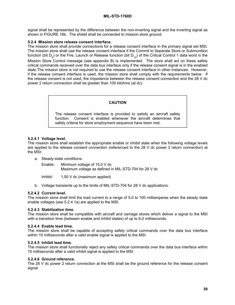
MIL-STD-1760D
39
signal shall be represented by the difference between the non-inverting signal and the inverting signal asshown in FIGURE 16b. The shield shall be connected to mission store ground.
5.2.4 Mission store release consent interface.The mission store shall provide connections for a release consent interface in the primary signal set MSI.The mission store shall use the release consent interface if the Commit to Separate Store or Submunitionfunction (bit D
8) or the Fire, Launch or Release function (bit D
10) of the Critical Control 1 data word in the
Mission Store Control message (see appendix B) is implemented. The store shall act on these safetycritical commands received over the data bus interface only if the release consent signal is in the enabledstate.The mission store is not required to use the release consent interface in other instances. However,if the release consent interface is used, the mission store shall comply with the requirements below. Ifthe release consent is not used, the impedance between the release consent connection and the 28 V dcpower 2 return connection shall be greater than 100 kilohms (at dc).
CAUTION
The release consent interface is provided to satisfy an aircraft safetyfunction. Consent is enabled whenever the aircraft determines thatsafety criteria for store employment sequence have been met.
5.2.4.1 Voltage level.The mission store shall establish the appropriate enable or inhibit state when the following voltage levelsare applied to the release consent connection (referenced to the 28 V dc power 2 return connection) atthe MSI:
a. Steady-state conditions:Enable: Minimum voltage of 15.0 V dc
Maximum voltage as defined in MIL-STD-704 for 28 V dc
Inhibit: 1.50 V dc (maximum applied)
b. Voltage transients up to the limits of MIL-STD-704 for 28 V dc applications.
5.2.4.2 Current level.The mission store shall limit the load current to a range of 5.0 to 100 milliamperes when the steady stateenable voltages (see 5.2.4.1a) are applied to the MSI.
5.2.4.3 Stabilization time.The mission store shall be compatible with aircraft and carriage stores which deliver a signal to the MSIwith a transition time (between enable and inhibit states) of up to 6.0 milliseconds.
5.2.4.4 Enable lead time.The mission store shall be capable of accepting safety critical commands over the data bus interfacewithin 10 milliseconds after a valid enable signal is applied to the MSI.
5.2.4.5 Inhibit lead time.The mission store shall functionally reject any safety critical commands over the data bus interface within10 milliseconds after a valid inhibit signal is applied to the MSI.
5.2.4.6 Ground reference.The 28 V dc power 2 return connection at the MSI shall be the ground reference for the release consentsignal.

MIL-STD-1760D
40
5.2.5 Mission store interlock interface.The mission store shall provide connections for an interlock interface in the primary signal set MSI(primary MSI) and in the auxiliary power signal set MSI (auxiliary MSI). The interlock interface at both theprimary and auxiliary MSI shall include an interlock connection and an interlock return connection. Thepath between the interlock and interlock return at the primary and auxiliary connectors shall have animpedance of 500 milliohms maximum over the frequency range of dc to 4 kHz when measured at theMSI. This impedance applies for excitation current within the range of 5.0 to 100 milliamperes. Theexcitation current from the connected aircraft or carriage store may be continuously applied or periodicallypulsed. The mission store shall comply with the requirements herein when the excitation signal opencircuit voltage applied to the MSI is between 3.5 V dc and MIL-STD-704 28 V dc upper voltage limits.The mission store shall electrically isolate both the interlock and interlock return connections at the MSIfrom all mission store circuits and grounds. The isolation shall be 100 kilohms minimum over thefrequency range of dc to 4 kHz.
5.2.6 Mission store address interface.The mission store shall include connections for an address interface in the primary signal set MSI fordetecting the assigned store data bus address. If the mission store needs to determine the mated statusof the MSI, it shall also use the address interface for this purpose. The address interface shall includefive binary encoded address bit connections (A
0, A
1, A
2, A
3, and A
4), one address parity connection and
one common address return connection. The characteristics defined below shall apply to the address bitand parity connections when referenced to the address return connection. Mission stores whichimplement the data bus interface (5.2.2) shall energize the address interface at the MSI to monitor thedata bus address assigned to the mission store by the connected aircraft or carriage store. Missionstores which do not implement the data bus interface are not required to use the address interface.
5.2.6.1 Address assignment.a. The mission store shall monitor the five binary encoded address bit connections at the MSI for
logic 0 and logic 1 states. The remote terminal address assigned to the MSI shall be defined as follows:Remote terminal address = (A
4) x 2
4 + (A
3) x 2
3 + (A
2) x 2
2 + (A
1) x 2
1 + (A
0) x 2
0
b. The mission store shall monitor the address parity connection at the MSI for logic 0 and logic 1states. The mission store shall accept the assigned address as a valid remote terminal address if theaddress parity connection logic state indicates odd parity. Odd parity is defined as an odd number oflogic 1 states on the six-bit set composed of the five address bit connections plus the address parityconnection. The mission store shall, as a minimum, determine its assigned address during theinitialization sequence of 5.2.12.
5.2.6.2 Address signal.The mission store shall provide excitation signals with the following characteristics:
a. Open circuit (logic 1) voltage:
(1) Minimum voltage of 4.0 V dc
(2) Maximum voltage of 31.5 V dc
(3) Rise and fall times of applied voltage shall not exceed 10 milliseconds when measured witha resistive load.
b. Logic 0 current:
(1) Minimum current of 5.0 milliamperes dc
(2) Maximum current of 100 milliamperes through each address bit and parity connection
(3) Maximum current of 600 milliamperes through the address return connection
(4) Rise and fall times of applied current shall not exceed 10 milliseconds when measured witha resistive load.

MIL-STD-1760D
41
5.2.6.3 Logic threshold.The mission store shall detect logic 0 and logic 1 states under the following conditions. The logic statedetection conditions apply to all valid and invalid address assignment combinations.
a. Logic 1: Any current level of 300 microamperes or less out of any address bit or address parityconnection when the excitation voltage of 5.2.6.2 is applied by the store shall be interpreted as a logic 1state.
b. Logic 0: Any voltage level of 1.50 V or less between any address bit (or parity) connection andthe address return connection when the excitation current of 5.2.6.2 is sourced by the store shall beinterpreted as a logic 0 state.
5.2.6.4 Response characteristics.The store shall allow 10 milliseconds minimum for logic state stabilization after application of theexcitation signal.
5.2.7 Mission store structure ground. [Note 19.] The mission store shall provide a conductive path from the MSI structure ground to mission storestructure, capable of carrying the overcurrent level defined in FIGURE 17 for the primary MSI interfaceand FIGURE 18 for the auxiliary MSI. The structure ground interface shall not be used as a signal returnpath or power return path except under fault conditions within the mission store. The voltage dropbetween the MSI structure ground interface and the mission store ground shall not exceed 0.2 volts whenconducting 10 amperes (continuous) for the primary MSI and 30 amperes (continuous) for the auxiliaryMSI.
5.2.8 Mission store 28 V dc power interface.The mission store shall provide connections for the 28 V dc power interface in the primary signal set MSI(primary MSI) and in the auxiliary power signal set MSI (auxiliary MSI). The primary MSI shall contain 28V dc power 1 and power 1 return connections and 28 V dc power 2 and power 2 return connections. Theauxiliary MSI shall contain a 28 V dc power connection and a 28 V dc power return connection. Themission store is not required to use any of the 28 V dc power interfaces. However, if any 28 V dc powerinterface is used, the mission store shall comply with the MSI requirements below. If any 28 V dc powerinterface is not used, the impedance between the unused power connection and the associated returnconnection at the MSI shall be greater than 100 kilohms (at dc).
5.2.8.1 Voltage level.The mission store shall be compatible with MSI voltages which comply with the 28 V dc normal andabnormal characteristics and voltage transients for utilization equipment defined in MIL-STD-704 with thefollowing addition. The mission store shall be compatible with a normal steady state lower voltage limit of20.0 V dc.
5.2.8.2 Load current.The mission store shall comply with the following load current requirements when the MSI voltage iswithin the range of 20.0 V dc to 29.0 V dc.
5.2.8.2.1 Primary signal set.Under fault free conditions, the mission store load applied at the primary MSI to each of the 28 V dcpower 1 and 28 V dc power 2 connections shall not exceed the maximum load current level of FIGURE17.
5.2.8.2.2 Auxiliary power signal set.Under fault free conditions, the mission store load applied at the auxiliary MSI shall not exceed themaximum load current level of FIGURE 18.
5.2.8.2.3 Simultaneous load.Under fault free conditions, mission stores with a class IA or IIA MSI shall limit the total simultaneouscurrent on all 28 V dc power interfaces in the primary and auxiliary MSI to the maximum load current levelof FIGURE 18.

MIL-STD-1760D
42
5.2.8.3 Load isolation.The mission store shall provide a minimum isolation of 100 kilohms (at dc) between the primary MSI 28 Vdc power 1 connection, the primary MSI 28 V dc power 2 connection and the auxiliary MSI 28 V dc powerconnection. The mission store may provide continuity between the associated 28 V dc power returnconnections.
5.2.8.4 Overcurrent compatibility.The mission store shall not become unsafe if fault currents up to the maximum overcurrent levels ofFIGURE 17 and FIGURE 18 are sourced into the primary and auxiliary MSIs, respectively.
5.2.8.5 Off-state leakage current.The mission store shall be compatible with off-state leakage currents supplied to the primary MSI up to1.0 milliampere dc between each 28 V dc power and its respective return. The mission store shall becompatible with off-state leakage currents supplied to the auxiliary MSI up to 2.50 milliamperes dcbetween auxiliary 28 V dc power and the associated 28 V dc power return.
5.2.8.6 Stabilization time.The mission store shall be compatible with MSI voltages which are below the levels of 5.2.8.1 herein forup to 6.0 milliseconds during power turn-on and turn-off (see FIGURE 19).
5.2.8.7 Ground reference.The 28 V dc power return connections at the primary and auxiliary MSIs shall be the reference for eachassociated 28 V dc power connection. The mission store shall be compatible with aircraft and carriagestores which connect the 28 V dc returns to aircraft structure ground. The mission store shall also becompatible with aircraft and carriage stores which isolate the 28 V dc returns from aircraft structuregrounds.
5.2.8.8 Power utilization.Mission stores shall use 28 V dc power 2 or auxiliary 28 V dc to power those safety critical functions forwhich insufficient interlocks exist in the store for assuring that the required level of store safety can beachieved once the associated power interface is activated. The store shall not execute any safety criticalfunctions (e.g., arm or employ) solely as a result of the activation of 28 V dc power 2 or auxiliary 28 V dcpower. Mission stores may use 28 V dc power 2 or auxiliary 28 V dc for powering non-safety critical storefunctions with the understanding that the aircraft will not energize these power interfaces until the aircrafthas determined that it is safe to do so. Mission stores shall use 28 V dc power 1 only for powering thosestore functions which are not safety critical or which have sufficient safety interlocks such that store safetyis not significantly degraded with the activation of 28 V dc power 1. Mission stores shall withstand withoutfunctional damage, the activation of any 28 V dc power interfaces prior to needed activation.
5.2.9 Mission store 115/200 V ac power interface.The mission store shall provide connections for the 115/200 V ac power interface in the primary signal setMSI (primary MSI) and in the auxiliary power signal set MSI (auxiliary MSI). Both the primary MSI andauxiliary MSI shall contain 115 V ac phase A, phase B, phase C, and neutral connections. The missionstore is not required to use any of the 115 V ac phases (see 4.3.8 and 4.4.1). However, if any 115 V acphase is used, the mission store shall comply with the MSI requirements below. If any 115 V ac phase isnot used, the impedance between the unused phase connection and the associated neutral connection atthe MSI shall be greater than 100 kilohms (at 400 Hz). The mission store shall not require the presenceof ac power at the MSI during actual store separation from the aircraft or carriage store, or duringconnector disconnect.
5.2.9.1 Voltage level.The mission store shall be compatible with MSI voltages which comply with the 115 V ac normal andabnormal characteristics and voltage transients for utilization equipment defined in MIL-STD-704 with thefollowing addition. The mission store shall be compatible with a normal steady state lower voltage limit of105.0 V RMS.

MIL-STD-1760D
43
5.2.9.2 Load current.The mission store shall comply with the following load current requirements when the MSI voltage iswithin the range of 105 and 118 volts RMS.
5.2.9.2.1 Primary signal set.Under fault free conditions, the mission store load applied at the MSI to each 115 V ac phase connectionshall not exceed the maximum load current level of FIGURE 17a. Mission stores designed for operationthrough carriage stores shall limit the phase load at the MSI to 90 percent of the maximum load currentlevel of FIGURE 17a.
5.2.9.2.2 Auxiliary power signal set.Under fault free conditions, the mission store load applied at the MSI to each 115 V ac phase connectionshall not exceed the maximum load current level of FIGURE 18a.
5.2.9.2.3 Simultaneous load.Under fault free conditions, mission stores with a class IA or IIA MSI shall limit the total simultaneous perphase current on all 115 V ac phase connections in the primary MSI and auxiliary MSI to the maximumload current level of FIGURE 18a. Mission stores designed for operation through carriage stores, shallnot exceed a 29 ampere continuous per phase load.
5.2.9.3 Load isolation. [Note 20.] The mission store shall provide a minimum isolation of 100 kilohms (at 400 Hz) between the primary MSI115 V ac phase connections and the auxiliary MSI 115 V ac phase connections.
5.2.9.4 Overcurrent compatibility.The mission store shall not become unsafe if fault currents up to the maximum overcurrent levels ofFIGURE 17a and FIGURE 18a are sourced into the primary and auxiliary MSI, respectively.
5.2.9.5 Off-state leakage current.The mission store shall be compatible with off-state leakage currents applied to the primary MSI up to 2.0milliamperes between each 115 V ac power phase and the 115 V ac neutral. The mission store shall becompatible with off-state leakage currents supplied to the auxiliary MSI up to 5.0 milliamperes betweeneach auxiliary 115 V ac power phase and the associated 115 V ac neutral.
5.2.9.6 Stabilization time.The mission store shall be compatible with MSI voltages which are below the levels of 5.2.9.1 herein forup to 6.0 milliseconds during power turn-on and turn-off (see FIGURE 19).
5.2.9.7 Load power factor.The mission store load for each phase at the MSI shall have a power factor within the limits of FIGURE20.
5.2.9.8 Phase unbalance.The mission store load at the MSI shall comply with the ac phase power utilization requirements of MIL-STD-704.
5.2.9.9 Ground reference. [Note 21.] The 115 V ac neutral connections in the primary and auxiliary MSIs shall be the reference for eachassociated 115 V ac phase connection. The 115 V ac neutral connections shall be isolated from eachother and from structure ground to a minimum impedance of 100 kilohms (at 400 Hz). Stores shall becompatible with aircraft which connect the 115 V ac neutrals to aircraft structure grounds.
5.2.9.10 Power utilization.Mission stores shall use 115/200 V ac power (primary and auxiliary) only for powering those storefunctions which are not safety critical or which have sufficient safety interlocks such that store safety isnot significantly degraded with the activation of 115/200 V ac. The mission store shall withstand withoutdamage, the activation or loss of any 115 V ac power phase at any time.

MIL-STD-1760D
44
5.2.10 Mission store 270 V dc power interface. [Note 17.] The mission store shall provide connections for the 270 V dc power interface in the primary signal setMSI (primary MSI) and in the auxiliary power signal set MSI (auxiliary MSI). The primary MSI shallcontain 270 V dc power and power return connections. The auxiliary MSI shall contain 270 V dc powerand power return connections. The mission store is not required to use any of the 270 V dc powerinterfaces (see 4.3.8 and 4.4.1). However, if any 270 V dc power interface is used, the mission storeshall comply with the MSI requirements below. If the 270 V dc power interface is not used, theimpedance between the unused power connection and the associated return connection at the MSI shallbe greater than 100 kilohms (at dc). The mission store shall not require the presence of 270 V dc powerat the MSI during actual store separation from the aircraft or carriage store, or during connectordisconnect.
5.2.10.1 Voltage level.The mission store shall be compatible with MSI voltages which comply with the 270 V dc normal andabnormal characteristics and voltage transients for utilization equipment defined in MIL-STD-704E or laterrevisions with the following addition. The mission store shall be compatible with a normal steady statelower voltage limit of 247.0 V dc.
5.2.10.2 Load current.The mission store shall comply with the following load current requirements when the MSI voltage iswithin the range of 247.0 V dc to 280.0 V dc.
5.2.10.2.1 Primary signal set.Under fault free conditions, the mission store load applied at the primary MSI to the 270 V dc powerconnection shall not exceed the maximum load current level of FIGURE 17b. Mission stores designed foroperation through carriage stores shall limit the load at the MSI to 90 percent of the maximum loadcurrent level of FIGURE 17b.
5.2.10.2.2 Auxiliary power signal set.Under fault free conditions, the mission store load applied at the auxiliary MSI shall not exceed themaximum load current level of FIGURE 18b.
5.2.10.2.3 Simultaneous load.Under fault free conditions, mission stores with a class IA or class IIA MSI shall limit the totalsimultaneous current on all 270 V dc power interfaces in the primary and auxiliary MSI to the maximumload current level of FIGURE 18b.
5.2.10.3 Load isolation.The mission store shall provide a minimum isolation of 100 kilohms (at dc) between the primary MSI 270V dc power connection and the auxiliary MSI 270 V dc power connection.
5.2.10.4 Overcurrent compatibility.The mission store shall not become unsafe if fault currents up to the maximum overcurrent levels ofFIGURE 17b and FIGURE 18b are sourced into the primary and auxiliary MSIs, respectively.
5.2.10.5 Off-state leakage current.The mission store shall be compatible with off-state leakage currents supplied to the primary MSI up to2.0 milliampere dc between each 270 V dc power connection and its return. The mission store shall becompatible with off-state leakage currents supplied to the auxiliary MSI up to 5.0 milliamperes dc betweenauxiliary 270 V dc power connection and the associated 270 V dc power return.
5.2.10.6 Stabilization time.The mission store shall be compatible with MSI voltages which are below the levels of 5.2.10.1 herein forup to 6.0 milliseconds during power turn-on and turn-off (see FIGURE 19).
5.2.10.7 Ground reference.The 270 V dc power return connection at the primary and auxiliary MSIs shall be the reference for eachassociated 270 V dc power connection. The 270 V dc return connections shall be isolated from eachother and from structure ground to a minimum impedance of 100 kilohms. The mission store shall be

MIL-STD-1760D
45
compatible with aircraft and carriage stores which connect the 270 V dc returns to aircraft structureground. The mission store shall also be compatible with aircraft and carriage stores which isolate the 270V dc returns from aircraft structure ground.
5.2.10.8 Power utilization.Mission stores shall use 270 V dc power (primary and auxiliary) only for powering those store functionswhich are not safety critical or which have sufficient safety interlocks such that store safety is notsignificantly degraded with the activation of 270 V dc. The mission store shall withstand without damage,the activation or loss of 270 V dc power at any time.
5.2.11 Mission store fiber optic interface.If a store uses fiber optic interfaces, the fiber optic interfaces shall comply with the requirements specifiedin 5.1.11 and subparagraphs. Use of the fiber optic interfaces by a mission store shall not occur until theoptical and logical (protocol) characteristics of the fiber optic interfaces are added to this standard. If fiberoptic interfaces are not used, the connector shall employ plugs that are compatible with an umbilicalwhich is populated with fiber optic termini.
5.2.12 Store initialization.Stores shall comply with the following initialization requirements in the sequence presented.
5.2.12.1 Pre-initialization conditions.The following pre-initialization conditions shall be provided to the store at the MSI (see 5.1.12.1):
a. All power interfaces deactivated.
b. Release consent interface in the inhibit state.
c. Address interface stabilized.
NOTE: Data bus interface, interlock interface, high bandwidth interfaces, low bandwidth interface, andfiber optic interfaces may be active.
5.2.12.2 Power application. [Note 18.] The store shall be compatible with simultaneous (within 100 milliseconds) application of primary 28 V dcpower 1 and either primary 270 V dc or primary 115/200 V ac power to the MSI in a non-predeterminedsequence. The store shall not require the application of any other interface power for completing theinitialization requirements specified herein.
5.2.12.3 Address determination.Within 150 milliseconds of interface power application (ac, dc, or both, as required by the store), the storeshall interrogate the address discretes (see 5.2.6.2) and accept the assigned address as the store's databus interface address.
5.2.12.4 First response.Within 150 milliseconds of interface power application (ac, dc, or both, as required by the store), the storeshall be capable of responding to valid commands received over the data bus interface. The requiredstore response shall be either:
a. A valid status word indicating a busy condition, or
b. A valid status word indicating a non-busy condition plus the appropriate valid data words.
If a store receives any commands before the 150 ms has transpired, the store shall either respond asdefined above or shall not respond at all.
5.2.12.5 First required non-busy response.Within 500 ms of interface power application (ac, dc, or both, as required by the store), the store shall becapable of responding to a valid store description message transmit command. This response shall be avalid status word indicating a non-busy condition plus the appropriate valid data words as defined inappendix B.

MIL-STD-1760D
46
5.3 Carriage store requirements.Carriage stores shall provide Carriage Store Interfaces (CSIs) and Carriage Store Station Interfaces(CSSIs) with the following characteristics.
5.3.1 Carriage store HB interfaces.The carriage store shall provide HB interfaces at each primary signal set CSI and CSSI for bi-directionalsimplex transfer of type A and type B signals. The CSI and CSSI shall contain all four HB interfaces(HB1, HB2, HB3, and HB4).
5.3.1.1 Minimum transfer capacity.The carriage store shall support (at a minimum of one CSSI at a time) the transfer of one type A signaland one type B signal (but not simultaneously) on HB1 simultaneously with the transfer of signals onHB2, HB3, and HB4 in accordance with TABLE I. The carriage store shall also support the unidirectionalbroadcast of HB signals from the CSI to multiple CSSIs on HB1 and HB2 in accordance with TABLE I.As a minimum, only one CSSI need be supported with HB signal transfers at a time. Routingconfigurations will be defined by the aircraft via the data bus.
TABLE I. Carriage store HB signal transfer.
Interface Applicability
either HB1 Type A -or-Point-to-point, bi-directional simplex, CSI to CSSI transfer. HB1 Type B
-simultaneously with-HB2 Type AHB3 Type AHB4 Type A.
Broadcast, uni-directional, CSI to CSSI(s) transfer. HB1 Type BHB2 Type A
5.3.1.2 Type A signal path characteristics.
5.3.1.2.1 Return loss.The input return loss of each signal path shall not be less than 20 dB over the frequency band 20 Hz to20 MHz when the output is terminated with the nominal impedance. The output return loss of each signalpath shall not be less than 20 dB over the frequency band 20 Hz to 20 MHz when the input is terminatedwith the nominal impedance.
5.3.1.2.2 Transient response.The carriage store network transient response shall be such that when each of the signals in FIGURE 5a,FIGURE 6a, FIGURE 7a, and FIGURE 8a is applied to the input, the output signal shall meet therequirements in FIGURE 5b, FIGURE 6b, and FIGURE 8b. For the output response envelope in FIGURE5b, V'1.0 is as defined in FIGURE 7b. For the response envelope in FIGURE 6b, V'1.3 is as defined inFIGURE 8b.
5.3.1.2.3 Insertion gain.The signal path insertion gain between the input and output shall be 0 dB +0.5/-1.0 dB, where insertiongain = 20 log (V'1.3 / V). V and V'1.3 are defined in FIGURE 8a and FIGURE 8b respectively.
5.3.1.2.4 Representative pulse delay.The representative pulse delay of any signal path shall not exceed 1.0 microsecond and shall not vary bymore than ±35 nanoseconds from its nominal value. The nominal value of the signal path representativepulse delay for the current routing path configuration shall be retained and made available for
MIL-STD-1760D
47
transmission to the aircraft if required. When the signal in FIGURE 8a is applied to the input, therepresentative pulse delay is the time difference between the voltage V/2 being reached on the inputsignal rising edge and the voltage V'1.3/2 being reached on the output signal rising edge where V'1.3 isdefined in FIGURE 8b.
5.3.1.2.5 Equalization.The gain misequalization of any signal path shall not exceed the limits shown in FIGURE 9. The zero dBgain reference shall be the gain at 20 kHz. The maximum gain between 20 MHz and 200 MHz shall notexceed +3 dB with respect to the zero-dB gain reference.
5.3.1.2.6 Dynamic range.When a 1 kHz, 3.5 Vpp sine wave is added to a dc voltage of ±0.25 V and then applied at the CSSI input,the signal at the output of the signal path shall not be compressed or clipped by more than 6 percent.When a 1 kHz, 3.5 Vpp sine wave is added to a dc voltage of ±0.75 V and then applied at the CSI input,the signal at the output of the signal path shall not be compressed or clipped by more than 6 percent.
5.3.1.2.7 Signal path dc offset.The maximum dc voltage at the output of each signal path shall not exceed ±250 mV with the inputterminated.
5.3.1.2.8 Noise.Noise at the type A signal path outputs shall meet the following requirements over the frequency band 20Hz to 20 MHz.
5.3.1.2.8.1 Random noise.Using the weighting function of FIGURE 10, the weighted noise power at each signal path output with theinput terminated shall not exceed -45 dBm RMS.
5.3.1.2.8.2 Periodic noise.The calculated periodic noise voltage at each signal path output with the input terminated shall notexceed 0.52 mVRMS for each valid state of the HB routing network. The noise voltage shall bedetermined by stimulating each HB and LB interface of the AEIS not associated with the signal path inturn by an in-band, maximum amplitude sinusoidal signal which produces the maximum weightedcrosstalk voltage at the signal path output. The weighting function is given in FIGURE 11. The frequencyof the stimulus signal may be different at each interface. The calculated periodic noise voltage shall bethe root sum of squares of the individual crosstalk voltages plus the unstimulated weighted periodic noisevoltage at the signal path output when all HB and LB interfaces are terminated.
5.3.1.2.8.3 Impulse noise.The impulse noise voltage at the signal path output with the input terminated shall not exceed 10 mV.
5.3.1.2.8.4 Stimulated noise.No more than -30 dBm of noise shall be added to the signal path noise at the output when a 1.3 Vppsinusoidal excitation signal of any frequency between 1 MHz and 15 MHz is applied to the input.
5.3.1.2.8.5 Common mode noise.Using the weighting function of FIGURE 12, the RMS common mode noise voltage at the output of eachsignal path shall not exceed 200 mV with respect to the output structure ground when the input isterminated and the input signal return is connected to the input structure ground.
5.3.1.3 Signal path electrical characteristics (type B).None specified at this time.
5.3.1.4 Ground reference (type A).When configured to carry type A signals, HB signal paths through the carriage store shall be either:
a. Passive, with the signal return (shield) electrically isolated from carriage store structure ground, asshown in FIGURE 21a, or

MIL-STD-1760D
48
b. Active, with the output signal return (shield) connected to carriage store structure ground and inputsignal return (shield) isolated from carriage store structure ground, as shown in FIGURE 21b.
5.3.1.5 Ground reference (type B).When configured to carry type B signals, the signal return (shield) shall be electrically connected tocarriage store structure ground at both the signal path input and output.
signal connection
signal return (shield)connection
INPUT OUTPUTSIGNAL PATH
signal return (shield) connection
signal connection
FIGURE 21a. Equivalent circuit of HB Type A passive signal path.
INPUT OUTPUTSIGNAL PATH
signal return (shield)connection
signalconnectionsignal
connectionequivalent
sinkimpedance
equivalentsourcevoltage
equivalent source impedence
signal return (shield)connection
FIGURE 21b. Equivalent circuit of HB Type A active signal path.
FIGURE 21. Equivalent circuits of carriage store HB Type A signal paths.
5.3.2 Carriage store data bus interface.The carriage store shall transfer data between the CSI and its CSSI(s) as commanded by the aircraft.
5.3.2.1 CSI.The carriage store shall provide two data bus interfaces (Mux A and Mux B) in the primary signal set CSI.Each of the Mux A and Mux B connections shall include a data high, a data low, and a shield connection.The data bus interfaces at the CSI shall meet the same functional and electrical characteristics as thedata bus interfaces at a MSI, as specified in 5.2.2.1 and 5.2.2.2.
5.3.2.2 CSSI.The carriage store shall provide two data bus interfaces (Mux A and Mux B) at each primary signal setCSSI. Each data bus interface shall include a data high, a data low, and a shield connection. The databus interfaces at the CSSI shall meet the same functional and electrical characteristics as the data businterfaces at an ASI, as specified in 5.1.2.1 and 5.1.2.2. [Note 11.]
5.3.3 Carriage store LB interface.The carriage store shall provide a LB interface at the CSI and at each CSSI for bi-directional simplextransfer of LB signals. Routing configurations will be defined by the aircraft via the data bus interface.When connected to source and sink equipment with impedances defined in 4.3.3, LB signal paths shallhave the following characteristics.

MIL-STD-1760D
49
5.3.3.1 Minimum transfer capacity.The carriage store shall support the transfer of LB signals between the CSI and any CSSI. As aminimum, only one CSSI need be supported with LB signal transfers at a time. Specific transfer capacitybeyond this minimum is not controlled by this standard.
5.3.3.2 Input/output impedance.The input impedance (line-to-line) of each signal path shall be 600 ohms ± 60 ohms, over the frequencyband 150 Hz to 8 kHz, when the output is terminated with the nominal sink impedance defined in 4.3.3.The output impedance (line-to-line) of each signal path shall be less than 60 ohms, over the frequencyband 150 Hz to 8 kHz, when the input is terminated with the nominal source impedance defined in 4.3.3.
5.3.3.3 Insertion gain.The signal path insertion gain between input and output shall be 0 dB +1 dB, -2 dB for a 1 kHz sine waveinput.
5.3.3.4 Equalization.The gain misequalization of any signal path shall not exceed the limits shown in FIGURE 22. The zerodB gain reference shall be at 1 kHz.
Frequency
8kHz3.4kHz1kHz300Hz150Hz
Gain
0dB
-1dB
+1dB
FIGURE 22. Maximum gain misequalization envelope (LB, carriage store).
5.3.3.5 Signal path dc offset.The maximum dc voltage at the output of each signal path shall not exceed ±1 V line-to-line and ±1 Vline-to-ground with the input terminated.
5.3.3.6 Noise.The signal path noise shall meet the following requirements over the frequency band 150 Hz to 8 kHzexcept where otherwise specified.
5.3.3.6.1 Periodic and random noise.The calculated periodic and random noise voltage at each signal path output with the input terminatedshall not exceed 6.5 mVRMS for each valid state of the LB routing network. The noise voltage shall bedetermined by stimulating each LB and HB interface of the AEIS not associated with the signal path inturn by an in-band (150 Hz to 8 kHz), maximum amplitude sinusoidal signal which produces themaximum crosstalk voltage at the signal path output. The frequency of the stimulus signal may bedifferent at each interface. The calculated noise voltage shall be the root sum of squares of the individualcrosstalk voltages plus the unstimulated periodic and random noise voltage at the signal path outputwhen all LB and HB interfaces are terminated.

MIL-STD-1760D
50
5.3.3.6.2 Impulse noise.With the input of the signal path terminated, there shall be (to one standard deviation) no more than oneoccurrence of impulse noise exceeding 20 mV peak over a three minute period. The impulse noisevoltage shall apply when band-limited to 8 kHz low pass.
5.3.3.6.3 Stimulated noise.For any frequency between 300 Hz and 3.4 kHz, application of a 12 Vpp sinusoidal excitation signal tothe signal path input shall not add more than 50 mV RMS of noise to the output over the frequency band150 Hz to 8 kHz.
5.3.3.6.4 Common mode noise.The peak common mode noise voltage at the output of each signal path (CSI and CSSI) shall not exceed±0.5 V when the input is terminated and the input shield is at the same potential as local structureground. This requirement shall apply over the band 150 Hz to 50 kHz.
5.3.3.7 Ground reference.LB signal paths through the carriage store shall be either:
a. Passive, as shown in FIGURE 23a, or
b. Active, with outputs referenced to carriage store ground, as shown in FIGURE 23b.
non-inverting signal connection
inverting signal connectionshieldshield
non-inverting signalconnection
inverting signal connection
INPUT OUTPUTSIGNAL PATH
FIGURE 23a. Equivalent circuit for LB passive signal path.
V1
V2
R1
R2
non-invertingsignal connection
inverting signal connection
shieldshield
non-invertingsignal connection
invertingsignal connection
INPUT OUTPUTSIGNAL PATH
Notes: 1. V1-V2 is the Thevenin equivalent voltage source (balanced with respect to ground). 2. R1+R2 is the Thevenin equivalent source impedance.
FIGURE 23b. Equivalent circuit for LB active signal path.
FIGURE 23. Equivalent circuits for LB carriage store signal paths.

MIL-STD-1760D
51
5.3.4 Carriage store release consent interface.The carriage store shall provide connections for a release consent interface at the CSI and each CSSI.
5.3.4.1 CSI.The carriage store shall use the release consent signal from the aircraft to enable/inhibit fire, launch,release, or jettison functions. The carriage store shall act on release consent-interlocked safety criticalcommands received over the data bus interface only if the release consent signal is in the enabled state.Release consent at a CSI shall meet the same requirements as release consent at an MSI, as stated inparagraphs 5.2.4.1 through 5.2.4.6.
5.3.4.2 CSSI.The carriage store shall provide a release consent interface at each primary signal set CSSI fortransferring an enable/inhibit signal to the connected store(s). Release consent, when in the enabledstate, shall indicate consent for stores to perform safety critical functions (such as missile launch from arail launcher or rocket firing from a dispenser) when commanded over the data bus interface. When inthe inhibited state, the release consent interface at a CSSI shall be electrically isolated from the releaseconsent interface at all other CSSIs. The isolation shall be 100 kilohms minimum at dc. Release consentat a CSSI shall meet the same requirements as release consent at an ASI, as stated in paragraphs5.1.4.1 through 5.1.4.6, with the following clarifications and exceptions:
a. If release consent is required by a store, the release consent signal shall attain the enable stateat least 10 milliseconds prior to transferring the safety critical command over the data bus interface orprior to the firing signal.
b. If release consent at a CSSI has been enabled, the carriage store shall operate under theassumption that the store connected to the CSSI may remain in an enable state for up to 10 millisecondsafter the release consent signal has returned to the inhibit state.
5.3.4.3 CSI to CSSI transfer.Release consent shall be in the enable state at the CSI before release consent can be in the enable stateat any CSSI. When release consent is in the inhibit state at the CSI, release consent shall be in theinhibit state at all CSSIs.
5.3.5 Carriage store interlock interface.The carriage store shall provide connections for an interlock interface in the primary signal set CSI and allprimary CSSI locations and also in the auxiliary power signal set CSI and all auxiliary CSSI locations.
5.3.5.1 CSI.The interlock interface at each primary and auxiliary CSI shall meet the same requirements as the MSIinterlock interface, as stated in 5.2.5.
5.3.5.2 CSSI.The carriage store shall monitor interlock and shall provide information to the aircraft (via the data businterface) on the mated status of each CSSI connector. The interlock interface at each primary andauxiliary CSSI shall meet the same open circuit voltage, excitation current, and impedance detectionthreshold requirements as the ASI interlock interface, as stated in 5.1.5.
5.3.5.3 Isolation.The carriage store shall electrically isolate both the interlock and interlock return connections at the CSIfrom all carriage store circuits and grounds. The interlock signal at each CSSI connector shall be isolatedfrom the interlock signal at all other CSSI connectors. The isolation shall be 100 kilohms or greater fromdc to 4 kHz.
5.3.6 Carriage store address interface.The carriage store shall provide connections for an address interface at the CSI and CSSI. Each addressinterface shall include five binary encoded address bit connections (A
0, A
1, A
2, A
3, and A
4), one address
parity connection and one common address return connection.

MIL-STD-1760D
52
5.3.6.1 CSI.The carriage store shall use the address interface from the aircraft for detecting the assigned store databus address and for determining the mated status of the CSI. The address interface at a CSI shall meetthe same requirements as the address interface at an MSI, as stated in paragraphs 5.2.6.1 through5.2.6.4.
5.3.6.2 CSSI.The carriage store shall provide an address interface at each primary signal set CSSI for assigning a databus address to the MIL-STD-1553 remote terminal in the mission store mated to the CSSI. The carriagestore shall use this interface only for assigning an address to the remote terminal associated with thedirectly connected mission store. The address interface at a CSSI shall meet the same requirements asthe address interface at an ASI, as stated in paragraphs 5.1.6.1 through 5.1.6.4.
5.3.7 Carriage store structure ground. [Note 19.]
5.3.7.1 CSI Structure Ground Characteristics.The carriage store shall provide a conductive path from the CSI structure ground to carriage storestructure, capable of carrying the overcurrent level defined in FIGURE 17 for the primary CSI interfacesand FIGURE 18 for the auxiliary CSI power interfaces. The structure ground interface shall not be usedas a signal return path or power return path except under fault conditions within the carriage store. Thevoltage drop between the CSI structure ground interface and carriage store ground shall not exceed 0.2volts when conducting 10 amperes (continuous) for the primary CSI and 30 amperes (continuous) for theauxiliary CSI.
5.3.7.2 CSSI Structure Ground Characteristics.The carriage store shall provide a conductive path from the CSSI structure ground to carriage storestructure, capable of carrying the overcurrent level defined in FIGURE 17 for the primary CSSI interfacesand FIGURE 18 for the auxiliary CSSI power interfaces. The structure ground interface shall not be usedas a signal return path or power return path except under fault conditions within the mission store. Thevoltage drop between the CSSI structure ground interface and carriage store ground shall not exceed 0.2volts when conducting 10 amperes (continuous) for the primary CSSI and 30 amperes (continuous) forthe auxiliary CSSI.
5.3.8 Carriage store 28 V dc power interface.The carriage store shall provide connections for the 28 V dc power interfaces at the CSI and the 28 V dcpower interfaces at the CSSI(s). The aircraft shall control all 28 V dc power. The primary signal set CSIand CSSI(s) shall contain 28 V dc power 1 and 28 V dc power 1 return connections and 28 V dc power 2and 28 V dc power 2 return connections. The auxiliary power signal set CSI and CSSI(s) shall contain a28 V dc power connection and a 28 V dc power return connection.
5.3.8.1 CSI.The 28 V dc power interfaces at the CSI shall meet the same requirements as the 28 V dc powerinterfaces at an MSI, as stated in paragraphs 5.2.8.1 through 5.2.8.8, except for the following: The CSIshall be compatible with a normal steady state lower voltage limit of 22.0 V dc, minus the drop in the ASIto CSI umbilical as defined in FIGURE 24.
5.3.8.2 CSSI.The 28 V dc power interfaces at each CSSI shall meet the same requirements as the 28 V dc powerinterfaces at an ASI, as stated in paragraphs 5.1.8.1 through 5.1.8.8, except for the following:
a. The normal steady state lower voltage limit at a CSSI shall be 20.0 V dc, plus the drop in theCSSI to MSI umbilical as defined in FIGURE 24.
b. The carriage store need not provide overcurrent protection as long as it is provided by the aircraftas required in 5.1.8.4.
5.3.9 Carriage store 115/200 V ac power interfaces.The carriage store shall provide connections for a set of three-phase four-wire wye-connected 115/200 Vac power interfaces at the CSI and at the CSSI(s). The aircraft shall control all 115/200 V ac power. The

MIL-STD-1760D
53
primary CSI and CSSI(s) and the auxiliary CSI and CSSI(s) shall contain 115 V ac phase A, phase B,phase C, and neutral connections.
5.3.9.1 CSI.The 115/200 V ac power interface at the CSI shall meet the same requirements as the 115/200 V acpower interfaces at an MSI, as stated in 5.2.9.1 through 5.2.9.10, except for the following: The CSI shallbe compatible with a normal steady state lower voltage limit of 108.0 V ac, minus the drop in the ASI toCSI umbilical as defined in FIGURE 24.
5.3.9.2 CSSI.The 115/200 V ac power interface at the CSSI shall meet the same requirements as the 115/200 V acpower interfaces at an ASI, as stated in paragraphs 5.1.9.1 through 5.1.9.11, except for the following:
a. The normal steady state lower voltage limit at a CSSI shall be 105 V ac, plus the drop in the CSSIto MSI umbilical as defined in FIGURE 24.
b. The carriage store shall be capable of providing at least 90 percent of the maximum load currentlevels of FIGURE 17a simultaneously through each of the three 115 V ac power phases of the primarysignal set CSSI.
c. The total 115 V ac continuous current provided simultaneously through both primary and auxiliaryinterfaces at any class IA CSSI need not exceed 29 amperes per phase.
d. The carriage store need not provide overcurrent protection as long as it is provided by the aircraftas required in 5.1.9.4.
CSI
ASI
CSSI CSSI
2*C * Imax + R*L2*Imax
2.0 Volts maxfor DC 1 & 2,3.0 Volts maxfor 115 V ac.,3.0 Volts maxfor 270 V dc
2*C * Imax + R*L1*Imax
C = Contact pair resistanceImax = Max rated current = 10 A for primary, 30 A for auxiliaryR = Resistance of umbilical per meterL = Length of umbilical cable, meters
Carriage store
MSI MSI
Notes: 1. Reference paragraph 5.4.8, 5.4.9 and 5.4.10 for contact resistance and umbilical cableresistance.
2. This figure does not place a specific voltage drop requirement on the carriage store, but ratherplaces a requirement on the total voltage drop allowed across the carriage store and the umbilicals it is tobe used with.
FIGURE 24. Carriage store voltage drop diagram.

MIL-STD-1760D
54
5.3.10 Carriage store 270 V dc power interfaces. [Note 17.] The carriage store shall provide connections for the 270 V dc power interfaces at the CSI and the 270 Vdc power interfaces at the CSSI(s). The carriage store shall provide the capability for the aircraft tocontrol all 270 V dc power. The primary signal set CSI and CSSI(s) shall contain 270 V dc power and 270V dc power return connections. The auxiliary power signal set CSI and CSSI(s) shall contain a 270 V dcpower connection and a 270 V dc power return connection.
5.3.10.1 CSI.The 270 V dc power interfaces at the CSI shall meet the same requirements as the 270 V dc powerinterfaces at an MSI, as stated in paragraphs 5.2.10.1 through 5.2.10.7, except for the following: The CSIshall be compatible with a normal steady state lower voltage limit of 250.0 V dc, minus the drop in the ASIto CSI umbilical as defined in FIGURE 24.
5.3.10.2 CSSI.The 270 V dc power interfaces at each CSSI shall meet the same requirements as the 270 V dc powerinterfaces at an ASI, as stated in paragraphs 5.1.10.1 through 5.1.10.8, except for the following:
a. The normal steady state lower voltage limit at a CSSI shall be 247 V dc, plus the drop in the CSSIto MSI umbilical as defined in FIGURE 24.
b. The carriage store need not provide overcurrent protection as long as it is provided by the aircraftas required in 5.1.10.4.
5.3.11 Carriage store fiber optic interface.All interface connectors at all CSIs and CSSIs shall include provisions for two fiber optic paths (FO1 andFO2). The fiber optic interfaces shall comply with the requirements specified in 5.1.11 andsubparagraphs. Use of the fiber optic interfaces by a carriage store shall not occur until the optical andlogical (protocol) characteristics of the fiber optic interfaces are added to this standard.
5.3.12 Carriage store initialization.Carriage stores shall comply with the same initialization requirements as a mission store, as stated inparagraphs 5.2.12 through 5.2.12.5. A carriage store shall be initialized by the aircraft prior to initializingmission stores connected to its CSSIs. Carriage stores, under control of the aircraft, shall comply withthe same procedure for initializing mission stores connected to MSSIs as the aircraft must meet forinitializing stores, as stated in paragraph 5.1.12 through 5.1.12.3.
5.4 Umbilical cable requirements.Unless otherwise specified, the following requirements apply to both the primary and auxiliary interfaceumbilical cables. The umbilical cable is an electrical harness assembly used to passively interconnect anASI to an MSI, an ASI to a CSI, or a CSSI to an MSI. The umbilical cable shall provide a directconnection from the interface at one end of the umbilical to the corresponding interface at the other endwith no other connections. Umbilical cable length is not specified herein, but should be standardizedwhere possible.
5.4.1 Primary umbilical HB interfaces.The HB interface cables in the umbilical shall meet the form, fit, function, and interface requirements ofMIL-C-17/113 cable for HB1 and HB2 and meet the form, fit, function, and interface requirements of MIL-C-17/94 for HB3 and HB4. The signal returns shall be electrically isolated from each other and theumbilical gross shield.
5.4.2 Primary umbilical data bus interface.The data bus interface shielded twisted pair cables in the umbilical shall comply with MIL-STD-1553 cablecharacteristics. The Mux A and Mux B shields shall be isolated (100 kilohms minimum at dc) from allumbilical circuits, shields, and connector shells.
MIL-STD-1760D
55
5.4.3 Primary umbilical LB interface.The LB cable in the umbilical shall comply with the same characteristics required in 5.4.2. The LB cableshield shall be isolated (100 kilohms minimum at dc) from all umbilical circuits, shields, and connectorshells.
5.4.4 Primary umbilical release consent interface.The release consent interface line shall have a resistance not exceeding 32 milliohms per meter length ofumbilical, plus 8.8 milliohms for each mated contact pair, when passing the worst case voltage andcurrent profiles defined in paragraphs 5.1.4.2 and 5.2.4.2.
5.4.5 Umbilical interlock interface.Each interlock interface line shall have a resistance not exceeding 32 milliohms per meter length ofumbilical, plus 8.8 milliohms for each mated contact pair, when passing the worst case voltage andcurrent profiles defined in paragraphs 5.1.5 and 5.2.5.
5.4.6 Primary umbilical address interface.Each address interface line shall have a resistance not exceeding 32 milliohms per meter length ofumbilical, plus 8.8 milliohms for each mated contact pair, when passing the worst case voltage andcurrent profiles defined in paragraphs 5.1.6.2 and 5.2.6.2.
5.4.7 Umbilical structure ground.The primary interface structure ground line shall have a resistance not exceeding 14 milliohms per meterlength of umbilical, plus 4.54 milliohms for each mated contact pair. The auxiliary power interfacestructure ground line shall have a resistance not exceeding 4 milliohms per meter length of umbilical, plus1.21 milliohms for each mated contact pair. For primary and auxiliary umbilicals, this requirement applieswhen passing the worst case voltages and steady state current defined in paragraph 5.1.7 and 5.2.7.
5.4.8 Umbilical 28 V dc power interface.Each primary interface 28 V dc power interface line shall have a resistance not exceeding 14 milliohmsper meter length of umbilical, plus 4.54 milliohms for each mated contact pair. Each auxiliary 28 V dcpower interface line shall have a resistance not exceeding 4 milliohms per meter length of umbilical, plus1.21 milliohms for each mated contact pair. For both umbilical types, the requirement applies whenpassing the worst case voltages and steady state current defined in paragraphs 5.1.8.2 and 5.2.8.2.
5.4.9 Umbilical 115 V ac power interface.Each primary 115 V ac power interface line shall have a resistance not exceeding 14 milliohms per meterlength of umbilical, plus 4.54 milliohms for each mated contact pair. Each auxiliary 115 V ac power lineshall have a resistance not exceeding 4 milliohms per meter length of umbilical, plus 1.21 milliohms foreach mated contact pair. For both umbilical types, the requirement applies when passing the worst casevoltages and steady state current profiles defined in 5.1.9.2 and 5.2.9.2.
5.4.10 Umbilical 270 V dc power interface. [Note 18.] Each primary interface 270 V dc power interface line shall have a resistance not exceeding 14 milliohmsper meter length of umbilical, plus 4.54 milliohms for each mated contact pair. Each auxiliary 270 V dcpower interface line shall have a resistance not exceeding 4 milliohms per meter length of umbilical, plus1.21 milliohms for each mated contact pair. For both umbilical types, the requirement applies whenpassing the worst case voltages and steady state current defined in paragraphs 5.1.10.3 and 5.2.10.2.
5.4.11 Primary umbilical fiber optic interface.The fiber optic interfaces shall comply with paragraph 5.1.11.
5.4.12 Umbilical gross shield.The umbilical cable shall include a gross shield enclosing the entire umbilical wire bundle (360 degreecoverage) and electrically connecting the connector shells on each end of the umbilical. The umbilicalshield shall be 360 degree bonded to the connector shell on each end of the umbilical. DC resistance ofthe bond between the shield and the connector shell shall not exceed 2.5 milliohms.

MIL-STD-1760D
56
5.5 Power interface interrupts.5.5.1 Mission store compatibility. [Note 22.] Power interrupts of 200 microseconds or less on 28 V dc, 270 V dc or 115 V ac power interfaces, or anycombination thereof, shall have no effect on store function. Full function, including communication, shallbe maintained during such interrupts and no power interrupt notification shall occur. For power interruptsgreater than 200 microseconds, the store may request full or partial initialization.
5.5.2 Carriage store compatibility. [Note 22.] Power interrupts of 200 microseconds or less on 28 V dc, 270 V dc or 115 V ac power interfaces, or anycombination thereof, shall have minimal effect on carriage store function, i.e., any carriage store functionnot maintained during the interrupt shall be re-established immediately following restoration of power.The following functions shall be maintained during interrupts of up to 200 microseconds: (1) allcomputing capabilities and (2) transmission/reception of data via the data bus interfaces. Furthermore,no re-initialization is permitted and no power interrupt notification shall occur. For power interruptsgreater than 200 microseconds, the carriage store may request full or partial initialization.
5.5.3 Aircraft compatibility. [Note 22.] The aircraft shall be compatible with stores which request full or partial store system initialization followingan interrupt to the 28 V dc, 270 V dc or 115 V ac power, or any combination thereof, in excess of thatallowed in 5.5.1 and 5.5.2.
5.5.3.1 Full initialization.If the store requests full initialization, then the aircraft shall use paragraphs 5.1.12.1 through 5.1.12.3 tosatisfy the request. The aircraft, however, is not required to request the store description messagedemanded in 5.1.12.3.
5.5.3.2 Partial initialization.If no partial initialization procedure has been agreed in the Interface Control Document between theaircraft and store, the aircraft shall substitute full initialization.
5.5.4 Store power interrupt notification.In the event that the store requires a full or partial initialization after a power interrupt in excess of thatallowed in paragraph 5.5.1 and 5.5.2, the store shall notify the aircraft utilizing the service request withvector word procedure in paragraphs B.4.1.5.4 through B.4.1.5.7. That procedure uses theasynchronous vector word (TABLE B- III) which shall indicate whether full or partial initialization (asdefined in the ICD) is required.
5.6 Connector characteristics.5.6.1 Primary interface connectors.
a. ASI and CSSI Type 1 (hand mated) connectors shall meet the form, fit, function, and interfacerequirements of MIL-DTL-38999/20 or /24, Series III, Shell Size 25, Polarization Key Identification Nconnectors. The contacts/termini and seal plugs/dummy contacts shall be compatible with the form, fit,function, and interface characteristics of those listed in TABLE II.
b. ASI and CSSI Type 2 (blind mated) connectors shall meet the form, fit, function, and interfacerequirements of the MIL-DTL-83538 Launcher Receptacle and be intermateable with the MIL-DTL-83538Buffer Plug. The receptacle contacts/termini and seal plugs/dummy contacts shall meet the form, fit,function, and interface characteristics of those listed in TABLE II.
c. MSI and CSI Type 1 (hand mated) connectors shall be intermateable with MIL-DTL-38999/31,Series III, Shell Size 25, Polarization Key Identification N connectors. The contacts/termini and sealplugs/dummy contacts used shall be intermateable with those listed in TABLE II.
d. MSI and CSI Type 2 (blind mated) connectors shall meet the form, fit, function, and interfacerequirements of the MIL-DTL-83538 Store Receptacle and shall be intermateable with the MIL-DTL-83538 buffer plug. The contacts/termini and seal plugs/dummy contacts used shall be intermateable withthose listed in TABLE II.

MIL-STD-1760D
57
e. The Type 2 Buffer Plug, which is the interconnecting mechanism used between the Type IILauncher Receptacle and the Type 2 Store Receptacle, shall meet the form, fit, function, and interfacerequirements of the MIL-DTL-83538 Buffer Plug and shall be intermateable with the MIL-DTL-83538Launcher Receptacle and Store Receptacle. The buffer plug shall use fixed contacts as defined inMIL-DTL-83538.
f. All primary signal set connector insert arrangements shall be in accordance with MIL-STD-1560,Insert Arrangement No. 25-20.
g. The contact assignments in all primary signal set connectors shall be in accordance with TABLEIII.
5.6.2 Auxiliary power interface connector.a. The connector shall meet the form, fit, function, and interface characteristics of a MIL-DTL-38999,
Series III, Shell Size 25, Polarization Key Identification A connector.
b. The contacts/termini and seal plugs/dummy contacts shall meet the form, fit, function, andinterface characteristics of those listed in TABLE IV.
c. All auxiliary power interface connector insert arrangements shall be in accordance with MIL-STD-1560, Insert Arrangement No. 25-11.
d. The contact assignments shall be in accordance with TABLE V.
5.6.3 Connector receptacle.The ASI, CSI, CSSI, and MSI primary and auxiliary connectors shall be receptacles with socket contactsor socket termini.
5.6.4 Plugged cavities. [Note 23.] The ASI may use plugged cavities in lieu of socket contacts for the 115 V ac or the 270 V dc interface(whichever is not used –see para 4.3.8). The ASI, CSI and CSSI may use dummy termini in lieu of activetermini for the fiber optic interface. The ASI may also use plugged cavities in lieu of socket contacts forthe HB2 and HB4 interfaces if only a class II interface is implemented. The Auxiliary ASI may use pluggedcavities in lieu of socket contacts for any unused interface. The MSI may use plugged cavities in lieu ofsocket contacts or socket termini for any unused interface. Details on seal plugs can be found in TABLEII and TABLE IV.
5.6.5 Umbilical primary interface connectors.The connectors on primary signal set umbilical cables shall be intermateable with the connectors andinsert arrangement defined in 5.6.1. The connectors on both ends of the cable shall be plugs with pincontacts. The lanyard release connector on the MSI end of the cable shall meet the form, fit, function,and interface requirements of MIL-C-38999/31. The contact assignments shall be compatible with thecontact assignments of TABLE III. The connectors may use plugged cavities in lieu of pin termini for thefiber optic interface.
5.6.6 Umbilical auxiliary interface connectors. [Note 24.] The connectors on auxiliary signal set umbilical cables shall be intermateable with the connectors andinsert arrangement defined in 5.6.2. The connectors on both ends of the cable shall be plugs with pincontacts. The lanyard release connector on the MSI end of the cable shall meet the form, fit, function,and interface requirements of MIL-C-38999/31. The contact assignments shall be compatible with thecontact assignments of TABLE V.
5.6.7 Connector keyway orientation.
5.6.7.1 ASI and CSSI.The connector keyway orientation shall conform to the following:
a. With the interface connector positioned such that the longitudinal axis of the connector (the axisthat traverses from the back of the connector through the center to the front of the connector) is in thehorizontal plane of the aircraft and the connector face is facing forward on the aircraft, the major (large)keyway shall be located in the up position (see FIGURE 25a).

MIL-STD-1760D
58
b. With the interface connector positioned such that the longitudinal axis of the connector is in thevertical plane of the aircraft and the connector face is facing down on the aircraft, the major (large)keyway shall be located in the forward position (see FIGURE 25b).
c. With the interface connector positioned such that the longitudinal axis of the connector is in thehorizontal plane of the aircraft and the connector face is facing aft of the aircraft, the major (large) keywayshall be located in the down position (see FIGURE 25c).
d. With the interface connector positioned such that the longitudinal axis of the connector is in thehorizontal plane of the aircraft and the connector face is facing inboard or outboard of the aircraft, themajor (large) keyway shall be located in the forward position (see FIGURE 25d).
5.6.7.2 MSI and CSI.The connector keyway orientation shall conform to the following:
a. With the connector mounted on the store top surface, the major keyway (large) shall be locatedforward.
b. With the connector mounted on the store aft vertical surface, the major keyway (large) shall belocated up.
5.6.7.3 Umbilical cable.The keyway orientation of the connectors at each end of the umbilical shall conform to FIGURE 25. Thecable shall have sufficient torsional flexibility to align the keyway of the connector at one end of theumbilical with the keyway of the connector at the opposite end.
5.6.8 Connector location.
5.6.8.1 ASI and CSSI.There is no defined location for the ASI connector. It should be located such that, wherever practicable,the umbilical can be standardized in length with other locations.
5.6.8.2 MSI and CSI.MSI and CSI connector location for Type I and type II connectors shall conform to MIL-A-8591.
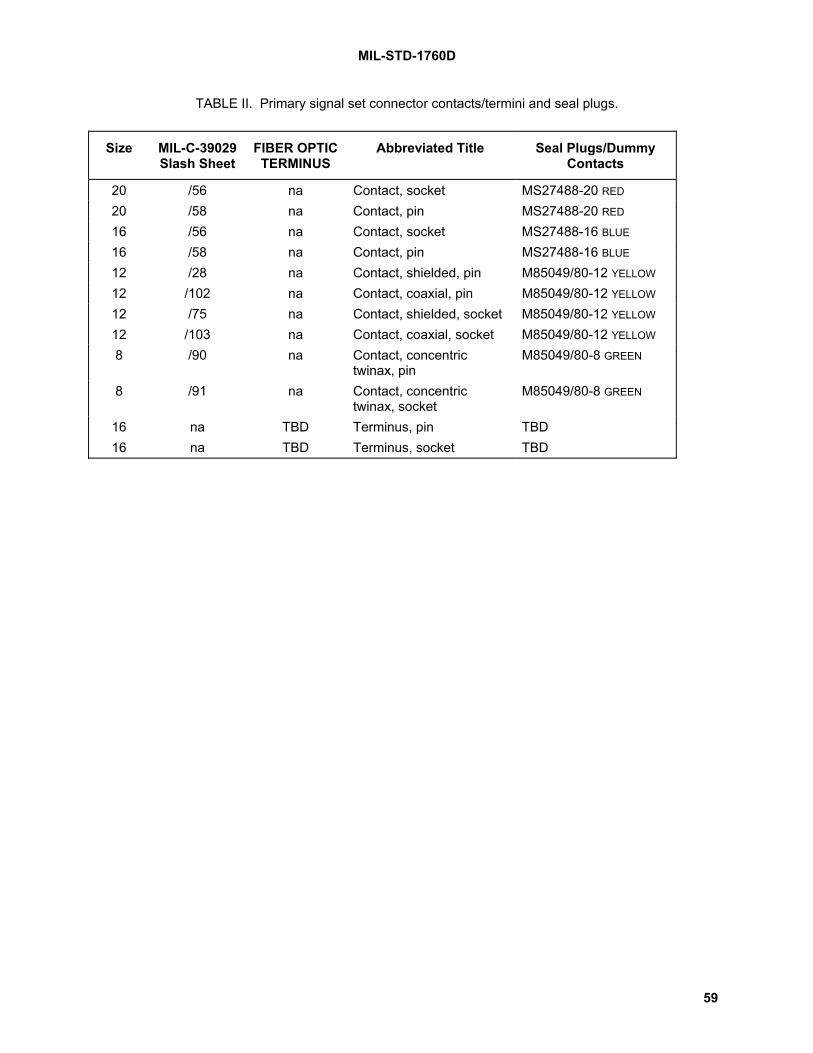
MIL-STD-1760D
59
TABLE II. Primary signal set connector contacts/termini and seal plugs.
Size MIL-C-39029Slash Sheet
FIBER OPTICTERMINUS
Abbreviated Title Seal Plugs/DummyContacts
20 /56 na Contact, socket MS27488-20 RED
20 /58 na Contact, pin MS27488-20 RED
16 /56 na Contact, socket MS27488-16 BLUE
16 /58 na Contact, pin MS27488-16 BLUE
12 /28 na Contact, shielded, pin M85049/80-12 YELLOW
12 /102 na Contact, coaxial, pin M85049/80-12 YELLOW
12 /75 na Contact, shielded, socket M85049/80-12 YELLOW
12 /103 na Contact, coaxial, socket M85049/80-12 YELLOW
8 /90 na Contact, concentrictwinax, pin
M85049/80-8 GREEN
8 /91 na Contact, concentrictwinax, socket
M85049/80-8 GREEN
16 na TBD Terminus, pin TBD16 na TBD Terminus, socket TBD
picklepa

MIL-STD-1760D
60
TABLE III. Primary signal set contact functional assignment. [Note 25.]
CONTACT LOCATION SIZE NOMENCLATURE
A 8 LB 1/B 20 InterlockC 16 28V DC power 1D 16 28V DC power 1 returnE 16 28V DC power 2 returnF 16 28V DC power 2G 20 Address parityH 8 Mux B 2/J 16 115V AC, phase C 4/K 8 Mux A 2/L 20 Address bit A
0M 16 115V AC, phase B 4/N 16 270V DC returnP 16 115V AC, phase A 4/R 16 270V DC powerS 20 Interlock returnT 16 Structure groundU 16 FO 2V 20 Address bit A
4W 12 5/ HB 2 3/X 20 Address bit A
1Y 16 FO 1Z 16 115V AC neutral1 20 Release consent2 12 6/ HB 4 3/3 12 6/ HB 3 3/4 20 Address bit A
35 12 5/ HB 1 3/6 20 Address return7 20 Address bit A
2
1/ The LB contact is a twinaxial style contact. LB signal assignments within the contact are:Center contact: Non-invertingIntermediate contact: InvertingOuter contact: Shield
2/ The Mux A and B contacts are a twinaxial style contact. Mux A and Mux B signalassignments within the contact are:
Center contact: Mux data highIntermediate contact: Mux data lowOuter contact: Mux shield
3/ The HB contacts are a coaxial style contact. Signal assignments within the contact are:Center contact: SignalOuter contact: Signal return (shield)
4/ Phase rotation shall comply with the requirements of 5.1.9.7.
5/ Contacts MIL-C-39029 /102, /103 only to be used.
6/ Contacts MIL-C-39029 /28, /75 only to be used.

MIL-STD-1760D
61
TABLE IV. Auxiliary power signal set connector contacts and seal plugs. [Note 26.]
Size MIL-C-39029Slash Sheet
Abbreviated Title Seal Plugs /Dummy Contacts
20 /56 Contact, socket MS27488-20 RED
20 /58 Contact, pin MS27488-20 RED
10 /56 Contact, socket M85049/81-8 GREEN
10 /58 Contact, pin M85049/81-8 GREEN
TABLE V. Auxiliary power signal set contact functional assignment.
CONTACT LOCATION SIZE NOMENCLATURE
A 10 115V AC, Phase A 1/
B 10 28V DCC 10 115V AC, Phase B 1/
D 10 28V DC returnE 10 115V AC, Phase C 1/
F 10 270V DCG 10 115V AC neutralH 10 270V DC returnJ 10 Structure groundK 20 InterlockL 20 Interlock return
1/ Phase rotation shall comply with the requirements of 5.1.9.7.
[Note 27.]

MIL-STD-1760D
62
UP
FORWARD
(ALL FIGURES)
MAJORKEYWAY
LONGITUDINALAXIS
LONGITUDINALAXIS
MAJORKEYWAY
MAJORKEYWAY
MAJORKEYWAY
LONGITUDINALAXIS
FIGURE 25c. Facing aft.
LONGITUDINALAXIS
FIGURE 25d. Facingoutboard/inboard.
FIGURE 25a. Facing forward. FIGURE 25b. Facing down.
FIGURE 25. Connector orientation.

MIL-STD-1760D
63
6. NOTES(This section contains information of a general or explanatory nature that may be helpful, but is notmandatory.)
6.1 Intended use.This standard is intended to be used for airborne military applications and applies to all aircraft and storesthat electrically interface with each other.
6.1.1 Implementation.Implementation and application of the standard are the responsibility of each military service, withtechnical guidance and direction provided by appropriate service program offices.
6.2 Issue of DoDISS.When this standard is used in acquisition, the issue of the DoDISS to be applicable to this solicitationmust be cited in this solicitation (see 2.2.1 and 2.3).
6.3 International standardization agreements.Certain provisions of this standard are subject to international standardization agreements: NATOSTANAG and ASCC Air Standard. When change notice, revision, or cancellation of this standard isproposed that will modify the international agreement concerned, the preparing activity will takeappropriate action through international standardization channels, including departmental standardizationoffices, to change the agreement or make other appropriate accommodations. It is intended that MIL-STD-1760 will be compatible with the following documents:
a. STANAG 3350, Analogue Video Standard for Aircraft System Applications;
b. STANAG 3837, Aircraft Stores Electrical Interconnection System
c. STANAG 3838, Digital Time Division Command/Response Multiplex Data Bus.
6.4 Tailoring guidance.MIL-STD-1760 defines a standard connector and signal interface between stores and aircraft. As such,most of the requirements are essential to the interoperability of these stores and aircraft; exceptions arediscussed in the draft handbook, which also discusses the design of the systems in the aircraft and storethat support and use this interface and must be tailored to the mission of the system.
6.5 Keyword listing.aircraftaircraft stationaudio signalsavionicsbus controllerdata worddiscrete signalselectrical connectorelectrical interfaceelectrical powerhigh bandwidth signalslow bandwidth signalsremote terminalserial data busstorestores management systemsuspension and release equipmentvideo signals

MIL-STD-1760D
64
6.6 Changes from previous issue.Major changes between revision C and revision D are explained by comments. These comments consistof a note number in parenthesis in the text, referring to a note in the list of notes that appears as appendixC. A Microsoft Word computer file, with revisions (additions, modifications, corrections, deletions) fromthe previous issue marked, along with the comments, is available to users from the Responsible Engineerat the preparing activity. The comments and the computer file with revisions marked are provided as aconvenience only and the Government assumes no liability whatsoever for any inaccuracies in thesenotations. Bidders and contractors are cautioned to evaluate the requirements of this document basedon the entire content irrespective of the change notations and relationship to the last previous issue.

MIL-STD-1760DAPPENDIX A
65
ADDITIONAL INTERFACE REQUIREMENTS FOR GPS RF SIGNALS [Note 28.]APPENDIX A
A.1. SCOPE
A.1.1 Purpose.This appendix shall be used to establish interface requirements on aircraft and mission stores for theNavstar Global Positioning System (GPS) RF signal assignment. For compliance with the standard,aircraft and mission stores are not required to support this signal assignment at system level. If theassignment is supported however, the requirements in this appendix shall be met.
A.2. APPLICABLE DOCUMENTS
A.2.1 References.The documents referenced in this appendix are not intended to be applied contractually.
A.2.2 Government documents, drawings and publications.
STANAG 4294 (Part 1) Navstar Global Positioning System (GPS) System Characteristics
A.3. DEFINITIONS, ACRONYMS AND ABBREVIATIONS
A.3.1 Definitions.The following definitions, in addition to those in section 3.0, apply to this appendix.
A.3.1.1 Navstar global positioning system (GPS).The Navstar GPS is a satellite-based radio-positioning, navigation and time transfer system withcharacteristics as defined in STANAG 4294.
A.3.1.2 L1 and L2.L1 and L2 are D-band carriers as specified in STANAG 4294.
A.3.1.3 Power gain.L1 gain is the power gain determined at the nominal frequency of the L1 carrier. L2 gain is the powergain determined at the nominal frequency of the L2 carrier.
A.3.1.4 Correlation loss.The following assumes that the input signal has no correlation loss as described in STANAG 4294. In aGPS signal distribution system, correlation loss is defined as the decibel difference between the signalpower in a 20.46MHz bandwidth that would be delivered to an output if the signal path exhibited zero gainmisequalization about the nominal carrier frequency, and the actual signal power that would be recoveredif an ideal correlation receiver of the same bandwidth were connected to that output.
A.3.1.5 Effective gain.In a GPS signal distribution system, the L1_P(Y) effective gain is defined as the L1 gain minus theL1_P(Y) correlation loss, the L2_P(Y) effective gain is defined as the L2 gain minus the L2_P(Y)correlation loss, and the L1_C/A effective gain is defined as the L1 gain minus the L1_C/A correlationloss. All values are in decibels.
MIL-STD-1760DAPPENDIX A
66
A.3.1.6 Figure of merit.In a GPS signal distribution system, figure of merit is defined as Ge - 10log10T, where Ge is the effectivegain in decibels and T is the output noise temperature in Kelvins.
A.3.1.7 Group delay.At any one frequency, group delay is defined as the local phase-frequency gradient between the systeminput and output in units of time.
A.3.1.8 Aircraft station GPS RF output.The aircraft station GPS RF output is the store-mating interface of the aircraft as depicted in FIGURE A-1.
A.3.1.9 L1_P(Y) signal.The L1_P(Y) signal is the L1P carrier component of L1, bi-phase shift key (BPSK) modulated by the P(Y)code plus data bit stream, as described in STANAG 4294.
A.3.1.10 L2_P(Y) signal.The L2_P(Y) signal is the L2 carrier, bi-phase shift key (BPSK) modulated by the P(Y) code plus data bitstream, as described in STANAG 4294.
A.3.1.11 L1_C/A signal.The L1_C/A signal is the L1C carrier component of L1, bi-phase shift key (BPSK) modulated by the C/Acode plus data bit stream, as described in STANAG 4294.
A.3.2 Acronyms and abbreviations.dBic decibels relative to an ideal, circularly-polarised isotropic antenna
dBK-1 decibels above 1 Kelvin-1
P(Y) GPS precision code, P or Y, as defined in STANAG 4294
C/A GPS coarse/acquisition code as defined in STANAG 4294
K Kelvins
SV space vehicle (GPS satellite)
Ge effective gain
T noise temperature in Kelvins
A.4. GENERAL REQUIREMENTS
A.4.1 Aircraft/store configurations.This appendix provides for the interface configurations depicted in FIGURE A- 1 by specifyingrequirements that are measurable at the aircraft station GPS RF output and the mission store interface(MSI).

MIL-STD-1760DAPPENDIX A
67
ASI
MSI
LAUNCHERRECEPTACLE
MSI
MISSIONSTORE
BUFFER
AIRCRAFT STATIONGPS RF OUTPUT
AIRCRAFT STATIONGPS RF OUTPUT
MISSIONSTORE
AIRCRAFT
(TYPE 2)
(TYPE 1)
(TYPE 1)
UMBILICALCABLE
(TYPE 2)
(NOTE 1)
AIRCRAFT
Note 1: The buffer must meet the electrical performance characteristics of MIL-DTL-83538A
FIGURE A- 1. GPS RF Interface configurations.
A.4.2 GPS RF signal requirements.Antenna-received GPS RF signals shall be transferred to the mission store over the High Bandwidth 1(HB1) Type B interface. The aircraft shall transfer L1_P(Y), L2_P(Y) and L1_C/A signals. The user-received GPS RF signal levels and SV viewing angle limits that the aircraft is required to be compatiblewith for the purposes of this appendix shall be defined in the aircraft system specification or similardocument.
A.5. AIRCRAFT REQUIREMENTSThe aircraft shall meet the following requirements at each aircraft station GPS RF output. Theserequirements apply with the interfaces terminated by the proper nominal impedance (50 ohms) andinclude the effect of the applicable mating contacts. Requirements shall apply over the frequency ranges:L1 ± 10.23 MHz for L1_P(Y), L2 ± 10.23 MHz for L2_P(Y) and L1 ± 1.023MHz for L1_C/A except whereindicated.
MIL-STD-1760DAPPENDIX A
68
A.5.1 Voltage standing wave ratio (VSWR).At each store station the maximum VSWR shall not exceed 2:1 at the L1 and L2 frequencies.
A.5.2 Effective gain.At each GPS RF output the effective gain (A.3.1.5) shall meet the following requirements, where 0dBic isdefined as the gain of an ideal isotropic right-hand circularly polarized antenna.
L1_P(Y) +9.0 dBic (min) to +30.5 dBic (max)
L2_P(Y) +7.0 dBic (min) to +28.0 dBic (max)
L1_C/A +9.0 dBic (min) to +33.0 dBic (max)
A.5.3 Group delay.The aircraft shall provide the nominal group delay at the L1 and L2 frequencies from the aircraft antennaphase center to each aircraft station GPS RF output. The value for each output is provided in theapplicable system specification of ICD.
A.5.4 Group delay uncertainty.The maximum group delay uncertainty shall be within ±35 ns at the L1 and L2 frequencies with respect tothe nominal group delay.
A.5.5 Figure of Merit.The minimum figure of merit shall meet the following requirements.
L1_P(Y) -35 dBK-1
L2_P(Y) -35 dBK-1
L1_C/A -45 dBK-1
A.5.6 Signal path dc offset.The maximum dc offset shall not exceed ± 250 millivolts when the output is terminated by an ideal 50ohm load. The aircraft shall meet the requirements of A.5.1 through A.5.5 herein with any store imposeddc offset of ± 500 millivolts.
A.6. MISSION STORE REQUIREMENTSThe mission store shall meet the following requirements at the MSI for the interface configurationsdepicted in FIGURE A- 1. These requirements apply with the interfaces terminated by the proper nominalimpedance (50 ohms) and include the effect of the applicable mating contacts. Requirements shall applyover the frequency ranges: L1 ± 1.023 MHz and L2 ± 1.023 MHz except where indicated.
A.6.1 Voltage standing wave ratio (VSWR).The maximum VSWR shall not exceed 2:1 at the L1 and L2 frequencies.
A.6.2 Signal power.The mission store shall be compatible with the following signal power levels.
L1_P(Y) -155.0 dBW (min) to -119.5 dBW (max)
L2_P(Y) -160.0 dBW (min) to -122.0 dBW (max)
L1_C/A -152.0 dBW (min) to -117.0 dBW (max)

MIL-STD-1760DAPPENDIX A
69
A.6.3 Signal to noise ratio.The mission store shall be compatible with the following minimum signal to noise ratios.
L1_P(Y) -42.5 dB
L2_P(Y) -45.5 dB
L1_C/A -39.5 dB
A.6.4 Signal path dc offset.The maximum dc offset generated by the mission store shall not exceed ± 500 millivolts when the input isterminated by an ideal 50 ohm source. The mission store shall meet the requirements of A.6.1 throughA.6.3 herein with any aircraft imposed dc offset of ± 250 millivolts.

MIL-STD-1760DAPPENDIX A
70
This page intentionally blank.

MIL-STD-1760DAPPENDIX B
71
DIGITAL DATA BUS COMMUNICATION RULESAND MESSAGE REQUIREMENTS
APPENDIX B
B.1 SCOPE
B.1.1 Purpose.This appendix shall be used to establish requirements on aircraft and stores for message formatting, dataencoding, information transfer rules, timing, and other characteristics required for using the digital databus interface of the AEIS.
B.2 APPLICABLE DOCUMENTS
B.2.1 References.The documents referenced in this appendix are not intended to be applied contractually.
B.2.2 Government documents.STANDARDS
Military
MlL-STD-1553B Not. 4 Aircraft Internal Time Division Command/Response Multiplex Data BusNOTE: Revision B Notice 4 is specifically required.
HANDBOOKS
Military
MIL-HDBK-1553 Multiplex Application Handbook
(Unless otherwise indicated, copies of federal and military specifications, standards, and handbooks areavailable from the Standardization Document Order Desk, 700 Robbins Avenue, Building 4D,Philadelphia, PA 19111-5094, phone (215) 697-2179 or http://assist.daps.dla.mil/quicksearch/ orhttp://www.dodssp.daps.mil/.)
B.2.3 Other Government documents, drawings, and publications.DEFENSE MAPPING AGENCY
WGS-84 Department of Defense World Geodetic System 1984
(Application for copies should be addressed to the Public Affairs Officer, Defense Mapping AgencyHydrographic/Topographic Center, Washington DC 20315-0030.)

MIL-STD-1760DAPPENDIX B
72
AMAC Standard
Aircraft Monitor and Control Project Officers Group System 2 specification:standard no. SYS 2001-01.
(Application for copies should be addressed to SA-ALC/NWIA, 1651 1st S E, Kirtland AFB NM 87117-5617.)
B.2.4 Non-Government publications.B.2.4.1 AMERICAN NATIONAL STANDARDS INSTITUTE
ANSI X3.4 Code for Information Interchange
(Application for copies should be addressed to the American National Standards Institute, Inc, 1430Broadway, New York NY 10018.)
B.2.4.2 INTERNATIONAL STANDARDS ORGANIZATIONISO 3166 Codes for the Representation of Names of Countries
(Application for copies should be addressed to the International Organization for Standardization, 1, ruede Varembe, Geneve, Switzerland or http://iso.ch/iso/en/ISOOnline.openerpage.)
B.2.4.3 SOCIETY OF AUTOMOTIVE ENGINEERSSAE-AS15531 Digital Time Division Command/Response Multiplex Data Bus
(Copies of SAE documents may be obtained from: Society of Automotive Engineers, Inc., 400Commonwealth Dr., Warrendale, PA 15096-0001, phone (412) 776-4841 orhttp://www.sae.org/misc/store.htm )
B.3 DEFINITIONS
B.3.1 Definitions.The following definitions, in addition to those in section 3.0, apply to this appendix.
B.3.1.1 Data entity.A data word which is encoded to represent specific information and which uses a defined data wordformat.
B.3.1.2 Data set.A group of data entities that are useful when taken together and are contained in a single message orgroup of messages.
B.3.1.3 Data validity.The condition in which the information encoded in the designated data word is sufficiently accurate for theapplication intended.
B.3.1.4 Mass data transfer.Mass data transfer refers to the transfer of data sets between aircraft and stores (or between stores)where the data set consists of more data words than can be transferred with only a few messages. Eachdata set is defined as a file. The protocol handles up to 255 files. Mass data transfer is implementedthrough the use of Transfer Control, Transfer Monitor, and Transfer Data messages.
B.3.1.4.1 Back-to-back transfer.Back-to-back transfer is defined as a mass data transfer operation in which data blocks (for either thesame record or for different records or files) are moved between aircraft and store through separateTransmit Data messages (with different subaddresses) with minimum intermessage gap. Back-to-backtransfer is typically used to reduce the time required for transferring large files.

MIL-STD-1760DAPPENDIX B
73
B.3.1.4.2 Block.A block is a record subset which can be transferred with one message transaction (BC-RT, RT-BC, orRT-RT). A block contains 29 (or 28 if the optional checksum word is used) sixteen bit words of file data.Blocks which do not contain file data in all 28 or 29 words are zero filled to complete the 29 word field.The 29 word field may include error detection word(s) in addition to file data.
B.3.1.4.3 Download.Download is defined as the process of transferring files into a store.
B.3.1.4.4 File.A file is a set of data related to specific information such as an operational flight program, a test ormaintenance program, mission data, bit patterns for memory test, etc. A file contains 1 to 255 datarecords.
B.3.1.4.5 Record.A record is a data subset containing 1 to 255 data blocks which when combined with other records formsa file.
B.3.1.4.6 Upload.Upload is defined as the process of transferring files out of the store.
B.3.1.4.7 Buffer.To initially locate or relocate in memory such that a subsequent mass data transfer does not overlay datareceived on a previous mass data transfer. It is also used to denote the storage memory that mass datatransfer occupies.
B.3.2 Acronyms and abbreviations.The acronyms and abbreviations in section 3.0 of the basic document apply to this appendix.
B.4 REQUIREMENTS
B.4.1 Communication rules.The data bus inteface shall comply with the requirements of MIL-STD-1553 with the additionalrequirements defined herein. The aircraft shall be responsible for the bus controller function for the ASI.The mission store shall provide the remote terminal function at the MSI. The carriage store shall providethe remote terminal function at the CSI and be responsible for the bus controller function at the CSSI.SAE-AS15531 may be used in lieu of MIL-STD-1553.
B.4.1.1 Command word.Command words shall be as defined by MIL-STD-1553. All command words shall be generated by anAEIS bus controller.
B.4.1.1.1 Remote terminal address field.The remote terminal address field shall be used to address the required store. If broadcast isimplemented, then the broadcast address shall be in accordance with MIL-STD-1553.
B.4.1.1.2 Subaddress/mode field.The subaddress/mode field shall be used for message identification and as a mode code indicator asdefined in TABLE B- I.
B.4.1.1.3 Mode commands.Aircraft and stores shall implement mode commands as defined herein. Aircraft and stores shall use asubaddress of 11111 (binary) as a mode code indicator. Stores shall also use subaddress 00000(binary) as a mode code indicator.

MIL-STD-1760DAPPENDIX B
74
B.4.1.1.3.1 Mandatory mode commands.Stores shall implement the mode commands as specified in B.4.1.1.3.1.1 through B.4.1.1.3.1.7. Aircraftshall, as a minimum, implement the mode commands specified in B.4.1.1.3.1.5 and B.4.1.1.3.1.6. If theaircraft uses the other mode commands defined in B.4.1.1.3.1.1 through B.4.1.1.3.1.7, theimplementation shall comply with these specified requirements.
B.4.1.1.3.1.1 Transmit status word.Stores shall implement and respond to valid transmit status word mode codes as required by MIL-STD-1553.
B.4.1.1.3.1.2 Transmitter shutdown.Stores shall implement and respond to valid transmitter shutdown mode codes as required by MIL-STD-1553. The shutdown transmitter shall not generate any bus activity until the mode code is overridden byeither an override transmitter shutdown mode code or a reset remote terminal mode code received on thenon-shutdown bus.
B.4.1.1.3.1.3 Override transmitter shutdown.Stores shall implement and respond to valid override transmitter shutdown mode codes as required inMIL-STD-1553 and B.4.1.1.3.1.2.
B.4.1.1.3.1.4 Reset remote terminal.Stores shall implement and respond to valid reset remote terminal mode codes as required by MIL-STD-1553. Receipt of this mode code shall re-enable all shutdown transmitters. The remote terminal is theonly element that shall be reset; the subsystem shall be unaffected.
B.4.1.1.3.1.5 Transmit vector word.Stores shall implement and respond to valid transmit vector word mode codes as required by MIL-STD-1553. The associated data word formats shall be as specified by TABLE B- II and TABLE B- III. Theaircraft shall issue transmit vector word mode codes during the request servicing process defined inB.4.1.5.5.
B.4.1.1.3.1.6 Synchronize with data word.Stores shall implement and respond to valid synchronize with data word mode codes as required by MIL-STD-1553. The synchronize with data word format shall use the TIME (L) format as defined in TABLE B-XXVII.
B.4.1.1.3.1.7 Transmit last command.Stores shall implement and respond to valid transmit last command mode codes as required by MIL-STD-1553.
B.4.1.1.3.2 Prohibited mode commands.Aircraft shall not transmit the dynamic bus control mode command, nor any of the reserved mode codesdesignated in MIL-STD-1553, nor any mode code not defined in MIL-STD-1553. If a store receives aprohibited mode command, the store shall not alter the state of the store subsystem.
B.4.1.1.3.3 Permitted mode commands.Stores may implement mode commands not defined as mandatory or prohibited. Stores implementingthe inhibit terminal flag bit mode command shall implement the override inhibit terminal flag bit modecommand. No store or aircraft shall require for operation that an aircraft or store implement a permittedmode command.
B.4.1.2 Status word.The status word shall be as defined by MIL-STD-1553. The status word bits at bit times 10, 12, 13, 14,and 18 shall be set to a logic zero. Bit time 10 shall not be used by a terminal, in conjunction with a logic1 in bit time 10 of the command word, to distinguish between a command word and a status word. Themessage error and broadcast command received bits shall be used as defined in MIL-STD-1553. Theservice request, busy, subsystem flag, and terminal flag bits shall be used as defined herein.

MIL-STD-1760DAPPENDIX B
75
B.4.1.2.1 Service request bit.The status word bit at bit time 11 shall be used only for request notification as specified in B.4.1.5.4.
B.4.1.2.2 Busy bit.The status word bit at bit time 16 shall be set to logic 1 only to notify that the RT is unable to move data toor from the store subsystem in compliance with a command. The busy bit shall only be set temporarily toa logic 1 and shall comply with B.4.1.5.3. The busy bit shall be the only indication that a message hasthus been discarded and no additional notification shall be implemented.
B.4.1.2.3 Subsystem flag bit.The status word bit at bit time 17 shall be used to indicate the presence of fault condition(s) within thestore or store-to-terminal interface which destroys the credibility of data words at the data bus interface.The bus controller shall interpret the subsystem flag bit as a total loss of store function. A logic zero shallindicate the absence of such an aforementioned store fault.
B.4.1.2.4 Terminal flag bit.The status word bit at bit time 19 shall be set to logic 1 only to indicate a detected fault in the RThardware. Stores not implementing the inhibit terminal flag bit mode command as specified in B.4.1.1.3.3shall set the terminal flag bit only if the fault is in that portion of the redundant RT to which the precedingcommand was sent. Stores detecting an interface address discrete error shall not interpret that error as aRT hardware fault.
B.4.1.3 Data words.Data words shall comply with MIL-STD-1553 and shall be sequenced and formatted as specified in B.4.2.
B.4.1.4 Internal state change.Stores shall not change the store subsystem state as a direct result of receiving a transmit command noras a direct result of receiving a receive command. In other words, store state changes shall occur whenthe contents of a receive message command a state change and shall not change because a receivemessage was only detected.B.4.1.5 Protocol execution.
B.4.1.5.1 Protocol checks.Protocol checks shall include the following verifications. Any message that fails any one of them shall bediscarded.
a. Verification of checksum, if implemented.b. Verification of message header.c. For the store control message, verification of the critical control 1, critical control 2, and critical
authority words shall be as follows:
(1) For a critical control 1 or critical control 2 word not marked invalid, both the IDENTIFIER andADDRESS CONFIRM fields must be correct. The invalidity, critical control 1, and critical control 2 wordsare defined in TABLE B- XXXI, TABLE B- XXXII, and TABLE B- XXXIII respectively.
(2) For the critical authority word, the CODED CHECK field must be correct. The criticalauthority word is defined in TABLE B- XXXIV.Detected errors in protocol checks shall be reported in accordance with B.4.2.2.2.
B.4.1.5.2 Checksum requirement.The use of checksums for the standard data messages specified in B.4.2.2.1, B.4.2.2.2, B.4.2.2.3,B.4.2.3.2.1.8 and B.4.2.3.2.2.9 are mandatory. The use of checksums for all other messages is optionaland determined by the store. When used, the checksum shall occupy the last word position of bothreceive and transmit messages and shall be formatted as specified in B.4.1.5.2.1. When not used, thelast word position shall be a data entity.

MIL-STD-1760DAPPENDIX B
76
B.4.1.5.2.1 Checksum algorithm.All checksummed messages shall include a checksum word which satisfies the following algorithm:When each data word (including the checksum word) of a message is rotated right cyclically by a numberof bits equal to the number of preceding data words in the message, and all the resultant rotated datawords are summed using modulo 2 arithmetic to each bit (no carries), the sum shall be zero. Thefollowing are examples of messages satisfying the checksum algorithm.
EXAMPLE (a): FOUR WORD MESSAGE1st Word 0000-0000-0000-0001 (0001 hex.) data2nd Word 1100-0000-0000-0000 (C000 hex.) data3rd Word 0000-1111-0000-0000 (0F00 hex.) data4th Word 0001-1110-0000-1011 (lE0B hex.) checksum word
EXAMPLE (b): SIX WORD MESSAGElst Word 0001-0010-0011-0100 (1234 hex.) data2nd Word 0101-0110-0111-1000 (5678 hex.) data3rd Word 1001-1010-1011-1100 (9ABC hex.) data4th Word 1101-1110-1111-0000 (DEF0 hex.) data5th Word 0000-0000-0000-0000 (0000 hex.) data6th Word 1000-1111-0010-0000 (8F20 hex.) checksum word
B.4.1.5.3 Execution time.If a store is to reject further messages while executing protocol checks on a previous received message,the store shall set the busy bit in the status word. The busy bit may only be set for the time specified inB.4.1.5.3.2 and only when one or more of the following criteria are met.
a. Acceptance of a valid initiate RT self test or reset RT mode command as specified in MIL-STD-1553.
b. Acceptance of a valid receive command (including synchronize with data word mode command).
c. During the initialization sequence of 5.2.2, or as a consequence of store fault or failure resultingin the inability of the RT to move data to or from the subsystem.
B.4.1.5.3.1 Aircraft compatibility.The aircraft shall be compatible with this execution time and busy bit application for store operation.
B.4.1.5.3.2 Busy time.Busy time is the duration for which the busy bit is set to logic 1. The maximum busy time following thereceipt of a valid initiate RT self test mode command or valid reset RT mode command shall comply withMIL-STD-1553. The maximum busy time following power application (ac, dc, or both, as required by thestore) shall not exceed 500 milliseconds. The maximum busy time for all other allowed busy conditionsshall not exceed 50 microseconds.
B.4.1.5.3.3 Busy time measurement.Busy time shall be the time measured from the zero crossing of the parity bit of the last word of theprevious message to the zero crossing of the first command word sync which is accepted and whosestatus response has the busy bit set to logic 0.

MIL-STD-1760DAPPENDIX B
77
B.4.1.5.4 Service request notification.Service request notification, if implemented by stores, shall be accomplished by setting the servicerequest bit in the status word to a logic 1. Stores shall ensure that once the service request bit is set tologic 1, the vector word as defined in B.4.1.1.3.1.5 is immediately available. The service request bit shallbe reset to logic 0 when, and only when, the store has received the transmit vector word mode commandfor the active service request and the vector word has been transmitted.
B.4.1.5.4.1 Additional request for service.All requests for servicing shall be covered by the one service request notification. The vector word shallcontain all the data concerning the request(s) for servicing indicated by the setting of status word bit time11. However, if further request for servicing occurs after status word bit time 11 has been set, then thatadditional request for servicing shall be treated as a new arising and shall not be actioned by the storeuntil the current service request has been completely dealt with. Stores shall not use multiple settings ofstatus word bit time 11 to avoid packing of more than one service request into the vector word demand.
B.4.1.5.5 Request servicing.The aircraft shall interpret the receipt of a store status word with service request bit set to logic 1 as arequest for a transmit vector word mode command. If, however, the service request bit is still set to alogic 1 in a second or subsequent response to the same service request, the service request bit shall bedisregarded by the aircraft. The aircraft shall extract information from the store on the service requestdetails by sending a transmit vector word command to the store. Acknowledgment of receipt of a validvector word shall not be a requirement on the aircraft.
B.4.1.5.6 Vector word demand.The store shall maintain the current contents of the vector word until a subsequent and different validcommand has been received after receiving a transmit vector word mode command. When specified inthe system specification or Interface Control Document (ICD), the store shall also maintain the currentcontents of any subaddress notified in the vector word until the requested data transaction has occurredand a subsequent and different valid command has been received.
B.4.1.5.7 General form of service request routine.The general form of a complete service request routine is shown in FIGURE B- 1.
B.4.1.5.8 Mass data transfer.Applications which require transfer of large data files through the AEIS interface shall use the applicableoptions of the mass data transfer procedure and messages defined in B.4.2.3.
B.4.1.5.9 Carriage store routing.A procedure for the transfer of data through a carriage store (routing) is not defined in this standardexcept as required by paragraph 5.1.2.1 d.
B.4.1.5.10 Data consistency.The aircraft and store shall ensure that messages transmitted over the bus contain only mutuallyconsistent samples of information. Different words in a message used to transmit multiple precisionparameters shall all be members of the same set.
B.4.1.5.11 Broadcast.Aircraft and stores are not required to implement broadcast. However, if implemented, then aircraft andstores shall comply with the following paragraphs.

MIL-STD-1760DAPPENDIX B
78
B.4.1.5.11.1 Broadcast restricted subaddresses.The bus controller shall not issue a broadcast command to the subaddresses given below.
SUBADDRESS TRANSMIT* RECEIVE00001 (01) x01000 (08) x x01011 (11) x x10011 (19) x x11011 (27) x x11110 (30) x
* The transmit column applies only to the transmitting remote terminal in RT-to-RT transfers.
B.4.1.5.11.2 Broadcast verification.The bus controller and stores which use broadcast shall implement some error detection scheme todetermine that broadcast messages were received correctly unless it is determined that errors in the databeing broadcast are not significant to system performance.
B.4.1.5.11.3 Broadcast command received bit.Stores shall implement the broadcast command received bit in the status word.
B.4.1.5.11.4 Stores compatibility with non-broadcast.A store which accepts broadcast messages shall also accept the same data in non-broadcast mode, i.e.,it will work with an aircraft or carriage store that does not do broadcast.
B.4.1.5.12 Time tagging. [Note 29.] Applications which require precision time referencing of transmit or receive data entities transferredbetween the aircraft and the store through the AEIS shall use the time tagging protocol defined inB.4.2.4.
B.4.2 Message requirements.Aircraft and stores shall use the standard message formats specified in B.4.2.2 and the mass datatransfer formats specified in B.4.2.3, as applicable. Safety critical data shall only be transferred in thestandard message formats of B.4.2.2.1, B.4.2.2.2, B.4.2.2.4, and B.4.2.2.5. All messages required by astore which are not defined in B.4.2.2 or B.4.2.3 shall:
a. employ the base message format specified in B.4.2.1, andb. use subaddresses selected in accordance with B.4.1.1.2.
B.4.2.1 Base message data format.All messages not covered by B.4.2.2 or B.4.2.3 shall use the base message format. The general formatis shown in TABLE B- VII, TABLE B- VIII, and TABLE B- IX. Messages to/from carriage stores may be ofany length up to the maximum of 32 data words. Messages to/from mission stores shall not exceed 30data words and if routed via a carriage store shall not exceed 30 data words when output at, or input to,the.
B.4.2.1.1 Data word 1.The first word of the message shall be a HEADER word for message identification. The HEADER wordshall be a hexadecimal code which complies with TABLE B- X and TABLE B- XLII.
B.4.2.1.2 Data words 2-32 and 2-30.Data words 2-32 are available for the transfer of up to 31 words of carriage store message data whichmay include a checksum. Data words 2-30 are available for the transfer of up to 29 words of missionstore message data which may include a checksum.

MIL-STD-1760DAPPENDIX B
79
B.4.2.2 Standard messages.Standard AEIS messages are defined as standard message data formats for safety critical control andmonitor functions of conventional and nuclear weapons and for store descriptions. A receive message isdefined as the data word or words received by a store in conjunction with a receive command word andthe status word response. A transmit message is defined as the status word and data word or wordstransmitted by a store resultant from a transmit command word.
B.4.2.2.1 Store control.The store control standard message shall be used for controlling the state of stores and specificallystandardizes the format for safety critical commands. Aircraft shall be capable of issuing this message tothe appropriate stores. Stores which require any of these safety critical commands shall implement thismessage. The store control message shall be a 30 data word receive message with a subaddress of 11(decimal) and formatted as specified in TABLE B- XI.
B.4.2.2.2 Store monitor.The store monitor standard message shall be used as a statusing message to reflect the safety criticalcondition of the store. The message also includes other non-safety critical store condition information.Aircraft shall be capable of issuing a transmit store monitor command and receiving the resulting monitormessage response from the store. Stores shall be capable of responding to a transmit store monitorcommand with the required status and data words. The store monitor message shall be a 30 data wordtransmit message with subaddress 11 (decimal) and formatted as specified in TABLE B- XII.
B.4.2.2.3 Store description.The store description standard message transfers store identity from the store to the aircraft. The storedescription message shall use subaddress 1 (decimal) and comply with the format of TABLE B- XIII. Themessage includes a header word, country code word, store identification words, maximum interruptiveBIT time word, store configuration identifier words, and a checksum word. The country code (see TABLEB- XIV) and store identification codes shall remain invariant through the life of the store or untilmodification to the store justifies a new store identity. The store identifier shall be either a binary code inaccordance with TABLE B- XV, or an ASCII code in accordance with TABLE B- XVI, or both. The aircrafthas the option of verifying or not verifying that the message passes the checksum test.
B.4.2.2.4 Nuclear weapon control.Receive messages with a subaddress field of 19 and 27 (decimal) shall only be used for control ofnuclear weapons. For all aircraft applications, usage of these subaddresses shall comply with the AircraftMonitor and Control Project Officers Group System 2 specification: standard no. SYS 2001-01.
B.4.2.2.5 Nuclear weapon monitor.Transmit messages with a subaddress field of 19 and 27 (decimal) shall only be used for monitor ofnuclear weapons. For all aircraft applications, usage of these subaddresses shall be in compliance withthe Aircraft Monitor and Control Project Officers Group System 2 specification: standard no. SYS 2001-01.
B.4.2.2.6 Aircraft description.The aircraft description standard message transfers aircraft identity from the aircraft to the store. Theaircraft description message shall use subaddress 1 (decimal) and comply with the format of TABLE B-XLVII. The message includes a header word, invalidity words, a country code word, aircraft identificationwords, a station number, a pylon/bay identity and a checksum word. The country code (see TABLE B-XIV) and aircraft identification codes shall remain invariant through the life of the aircraft or untilmodification to the aircraft justifies a new aircraft identity. The aircraft identifier shall be an ASCII code inaccordance with TABLE B- XVI. The store has the option of verifying or not verifying that the messagepasses the checksum test. The aircraft description message shall only be used with prior agreement viathe system specification or interface control document.

MIL-STD-1760DAPPENDIX B
80
B.4.2.3 Mass data transfer messages.Aircraft and stores which require Mass Data Transfer (MDT) operations shall use the applicableoperations defined herein. MDT shall be implemented through the use of three data message types. TheTransfer Control (TC) message (B.4.2.3.2.1) is a standard receive message for controlling the transferoperating modes and designation of file, record, and block numbers. The Transfer Monitor (TM)message (B.4.2.3.2.2) is a standard transmit message for monitoring the status of the mass data transferoperations in the store. The Transfer Data (TD) message (B.4.2.3.2.3) is a standard transmit, or standardreceive, message for transferring the file data blocks between aircraft and stores (or between stores).The system specification or interface control document defines the applicable operations, specific datafiles, and file data formats to be transferred using the MDT protocol.
B.4.2.3.1 File Structure.Each selected file (Sf) to be transferred using the MDT protocol shall be divided into 1 to 255 consecutiverecords (Nr) with each record divided into 1 to 255 consecutive blocks (Nb). Each block is transferredwith a single TD message and shall contain 30 words with word one being the record/block number andthe remaining 29 words used for file data (see B.4.2.3.2.3.2 and B.4.2.3.2.3.3). All records within aspecific file shall contain the same number of blocks. Unused words in each record shall be zero-filled.
B.4.2.3.2 Message formats.
B.4.2.3.2.1 Transfer Control (TC) message.The TC message shall be sent as a receive message to subaddress 14 and formatted in accordance withTABLE B- XVII. The aircraft shall set the TC message in accordance with the following requirements.
B.4.2.3.2.1.1 TC message - header word.The aircraft shall set this word in accordance with paragraph B.4.2.1.1.
B.4.2.3.2.1.2 TC message - instruction word.This word shall be formatted in accordance with TABLE B- XVIII and the INSTRUCTION TYPE field shallbe set to one of the valid bit combinations of TABLE B- XIX. If the aircraft requires the store to enable theecho of the TD message (TABLE B- XXIV) to the aircraft then the aircraft shall set bit 07 to logic 1, elsebit 07 shall be set to logic zero. If the format of the Sf data being transferred to/from the store includes anembedded message checksum in word 30 of every TD message, the aircraft shall set bit 12 to logic 1,else bit 12 shall be set to logic zero.
B.4.2.3.2.1.3 TC message - subaddress select word.This word shall be formatted in accordance with TABLE B- XX. The aircraft shall set this word to 0000Hex for all bit combinations in TABLE B- XIX except 1, 3, and 10. For bit combination 1, if the aircraftrequires the store to update the status of the TM message for a TD message sent to a particularsubaddress, the aircraft shall set this word to the subaddress for the TD message it requires the status of,else this word shall be set to 0000 Hex. For bit combination 3 or 10 of TABLE B- XIX, in applicationswhere the store can use different subaddresses for file data transfer, this word shall be set to thereceive/transmit subaddress for the TD message. The system specification or interface control documentshall identify those subaddresses available for the TD messages and the number of different files,records, or blocks that can be transferred through those different subaddresses. As an alternative, thesystem specification or interface control document may pre-assign specific subaddresses to specific file,record, or block numbers and then the subaddress select word shall be set to 0000 hexadecimal, or tothe applicable pre-assigned subaddress.
B.4.2.3.2.1.4 TC message - file number word.The aircraft shall set the NUMBER A and NUMBER B fields (TABLE B- XXI) of word 04 of the TCmessage as follows. NUMBER A and NUMBER B are valid file numbers ranging from 1 through 255.
a. For TABLE B- XIX bit combination numbers 1, 2, 4, 9, and 14, NUMBER A = 00 Hex andNUMBER B = 00 Hex.
b. For TABLE B- XIX bit combination 3, NUMBER A = Nf to be downloaded and NUMBER B = thenumber of the Sf in which the current download operation will be executed.

MIL-STD-1760DAPPENDIX B
81
c. For TABLE B- XIX bit combination 5, NUMBER A = 01 Hex and NUMBER B = the number of theSf to be erased.
d. For TABLE B- XIX bit combination 6, NUMBER A = 01 Hex and NUMBER B = the number of theSf in which the Sr will be erased.
e. For TABLE B- XIX bit combination 7, NUMBER A = 01 Hex and NUMBER B = the number of theSf to be checksummed.
f. For TABLE B- XIX bit combination 8, NUMBER A = 01 Hex and NUMBER B = the number of theSf in which the Sr will be checksummed.
g. For TABLE B- XIX bit combination 10, NUMBER A = Nf to be uploaded and NUMBER B = thenumber of the Sf in which the current upload operation will be executed.
h. For TABLE B- XIX bit combination 11, NUMBER A = 01 Hex and NUMBER B = the number of theSf in which the checksum value is embedded that the store is required to authenticate against thefile/record checksum word in this message.
I. For TABLE B- XIX bit combination 12, NUMBER A = 01 Hex and NUMBER B = the number of theSf where the Sr is located, in which the checksum value is embedded that the store is required toauthenticate against the file/record checksum word in this message.
j. For TABLE B- XIX bit combination 13, NUMBER A = 00 Hex and NUMBER B = the number of theSf in which execution will start in download mode; In upload mode, set to 00 Hex.
B.4.2.3.2.1.5 TC message - record number word.The aircraft shall set the NUMBER A and NUMBER B fields (TABLE B- XXI) of word 05 of the TCmessage as follows. NUMBER A and NUMBER B are valid file numbers ranging from 1 through 255.
a. For TABLE B- XIX bit combination numbers 1, 2, 4, 7, 9, 11, and 14, NUMBER A = 00 Hex andNUMBER B = 00 Hex.
b. For TABLE B- XIX bit combination number 3, NUMBER A = Nr for the Sf to be downloaded. Thevalue of Nr will remain fixed for the Sf during the commanded operation. NUMBER B = the number of theSr in which the current download operation will start.
c. For TABLE B- XIX bit combination number 5, NUMBER A = the Nr for Sf to be erased andNUMBER B = 01 Hex. The value of Nr will remain fixed for the Sf during the commanded operation.
d. For TABLE B- XIX bit combination number 6, NUMBER A = 01 Hex and NUMBER B = thenumber of the Sr to be erased.
e. For TABLE B- XIX bit combination number 8, NUMBER A = 01 Hex and NUMBER B = thenumber of the Sr to be checksummed.
f. For TABLE B- XIX bit combination 8, NUMBER A = 01 Hex and NUMBER B = the number of theSf in which the Sr will be checksummed.
g. For TABLE B- XIX bit combination 10, NUMBER A = Nf to be uploaded and NUMBER B = thenumber of the Sf in which the current upload operation will be executed.
h. For TABLE B- XIX bit combination 11, NUMBER A = 01 Hex and NUMBER B = the number of theSf in which the checksum value is embedded that the store is required to authenticate against thefile/record checksum word in this message.
I. For TABLE B- XIX bit combination 12, NUMBER A = 01 Hex and NUMBER B = the number of theSf where the Sr is located, in which the checksum value is embedded that the store is required toauthenticate against the file/record checksum word in this message.
j. For TABLE B- XIX bit combination 13, NUMBER A = 00 Hex and NUMBER B = the number of theSf in which execution will start in download mode; In upload mode, set to 00 Hex.
B.4.2.3.2.1.5 TC message - record number word.The aircraft shall set the NUMBER A and NUMBER B fields (TABLE B- XXI) of word 05 of the TCmessage as follows. NUMBER A and NUMBER B are valid file numbers ranging from 1 through 255.

MIL-STD-1760DAPPENDIX B
82
a. For TABLE B- XIX bit combination numbers 1, 2, 4, 7, 9, 11, and 14, NUMBER A = 00 Hex andNUMBER B = 00 Hex.
b. For TABLE B- XIX bit combination number 3, NUMBER A = Nr for the Sf to be downloaded. Thevalue of Nr will remain fixed for the Sf during the commanded operation. NUMBER B = the number of theSr in which the current download operation will start.
c. For TABLE B- XIX bit combination number 5, NUMBER A = the Nr for Sf to be erased andNUMBER B = 01 Hex. The value of Nr will remain fixed for the Sf during the commanded operation.
d. For TABLE B- XIX bit combination number 6, NUMBER A = 01 Hex and NUMBER B = thenumber of the Sr to be erased.
e. For TABLE B- XIX bit combination number 8, NUMBER A = 01 Hex and NUMBER B = thenumber of the Sr to be checksummed.
f. For TABLE B- XIX bit combination number 10, NUMBER A = Nr for the Sf to be uploaded andNUMBER B = the number of the Sr in which the current upload operation will start. The value of Nr willremain fixed for Sf during the commanded operation.
g. For TABLE B- XIX bit combination number 12, NUMBER A = 01 Hex and NUMBER B = thenumber of the Sr in which the checksum value is embedded that the store is required to authenticateagainst the file/record checksum word in this message.
h. For TABLE B- XIX bit combination number 13, NUMBER A = 00 Hex and NUMBER B = thenumber of the Sr of the Sf in which execution will start in download mode; in upload mode, set to 00 Hex.
B.4.2.3.2.1.6 TC message - block number word.The aircraft shall set the NUMBER A and NUMBER B fields (TABLE B- XXI) of word 06 of the TCmessage as follows. NUMBER A and NUMBER B are valid file numbers ranging from 1 through 255.
a. For TABLE B- XIX bit combination numbers 1, 2, 4, 7, 8, 9, 11, 12, and 14, NUMBER A = 00 Hexand NUMBER B = 00 Hex.
b. For TABLE B- XIX bit combination number 3, NUMBER A = Nb for the Sr of the Sf to bedownloaded and NUMBER B = the number of the Sb of the download operation which will be in the nextTD message. The value of Nb will remain fixed for the Sr during the commanded operation.
c. For TABLE B- XIX bit combination number 5, NUMBER A = Nb of the Sr for the Sf to be erasedand NUMBER B = 01 Hex. The value of Nb will remain fixed for the Sr during the commanded operation.
d. For TABLE B- XIX bit combination number 6, NUMBER A = Nb of the Sr for the Sf to be erasedand NUMBER B = 01 Hex. The value of Nb will remain fixed for the Sr during the commanded operation.
e. For TABLE B- XIX bit combination number 10, NUMBER A = Nb of the Sr for the Sf to beuploaded and NUMBER B = the number of the Sb that the store will transmit in the next TD message.The value of Nb will remain fixed for the Sr during the commanded operation.
f. For TABLE B- XIX bit combination number 13, NUMBER A = 00 Hex and NUMBER B = thenumber of the Sb of the Sr of the Sf in which execution will start in download mode; in upload mode, setto 00 Hex.
B.4.2.3.2.1.7 TC message - file/record checksum word.The aircraft shall set word 6 of the TC message as follows:
a. For TABLE B- XIX bit combination numbers 1, 2, 3, 4, 5, 6, 9, 10, 13, and 14, set to 0000 Hex.
b. For TABLE B- XIX bit combination number 7, either set to the checksum for the file as specified inparagraph B.4.2.3.4 or, if the checksum is embedded in the file/record data, this word shall be set to 0000hexadecimal. If the checksum is embedded, the checksum algorithm shall be as specified in the systemspecification or interface control document.
c. For TABLE B- XIX bit combination number 8, either set to the checksum for the record asspecified in paragraph B.4.2.3.4 or, if the checksum is embedded in the file/record data, this word shall be

MIL-STD-1760DAPPENDIX B
83
set to 0000 hexadecimal. If the checksum is embedded, the checksum algorithm shall be as specified inthe system specification or interface control document.
d. For TABLE B- XIX bit combination number 11, set to the aircraft calculated checksum for theuploaded file as specified in paragraph B.4.2.3.4. If the checksum is embedded in the file/record data, itshall be set as specified in the system specification or interface control document.
e. For TABLE B- XIX bit combination number 12, set to the aircraft calculated checksum for theuploaded record as specified in paragraph B.4.2.3.4. If the checksum is embedded in the file/record data,it shall be set as specified in the system specification or interface control document.
B.4.2.3.2.1.8 TC message - checksum word.The aircraft shall provide the TC message checksum as required in paragraph B.4.1.5.2.
B.4.2.3.2.2 Transfer Monitor (TM) message.The TM message shall be sent in a transmit message from subaddress 14 and formatted in accordancewith TABLE B- XXII. The store shall set the TM message in accordance with the following requirements.
B.4.2.3.2.2.1 TM message - header word.The store shall set this word in accordance with paragraph B.4.2.1.1.
B.4.2.3.2.2.2 TM message - last received instruction word.The store shall set this word to the last instruction word (word 02) received in an error free TC message(TABLE B- XVIII).
B.4.2.3.2.2.3 TM message - transfer mode status word.This word shall be formatted in accordance with TABLE B- XXIII and the MODE STATUS field shall beset to one of the valid bit combinations specified inTABLE B- XXV to reflect the status of the stores last data transfer operation.
B.4.2.3.2.2.4 TM message - current selected subaddress word.This word shall be set to the subaddress selected in the TC message (data word 03) or the subaddress inwhich the last TD message was received, whichever was last received by the store. If the store isrequesting retransmission of a record or block, the store shall set this word to the subaddress the aircraftis to transmit the TD message to, unless the system specification or interface control document pre-assigns specific subaddresses to specific file, record, or block numbers, in which case, the store shall setthis word to 0000 Hex.
B.4.2.3.2.2.5 TM message - current file number word.The mission store shall format this data word in accordance with TABLE B- XXI. The NUMBER A fieldshall reflect the Nf designated in word 04 of the last valid TC message. The NUMBER B field shall reflectthe current active Sf. The current active file number is defined as one of the following:
a. The number received in the NUMBER B field of the TC message File number word,
b. The number of the file on which the store is currently performing data transfer operations.If the store sets the MODE STATUS field to bit combination 16 ofTABLE B- XXV the store shall set the NUMBER A field to 01 hex, and the NUMBER B field to the filenumber for which the retransmission of data is needed.
B.4.2.3.2.2.6 TM message - current record number word.The mission store shall format this data word in accordance with TABLE B- XXI. The NUMBER A fieldshall reflect the total number of records (Nr) designated in word 05 of the last valid TC message for thecurrent Sf. The NUMBER B field shall reflect the Sr. The current active record number is defined as oneof the following
a. The number received in the NUMBER B field of the TC message Record number word,
b. The NUMBER A field of the record/block word of the last TD message received/transmitted,whichever was last processed.

MIL-STD-1760DAPPENDIX B
84
If the store sets the MODE STATUS field to bit combination 16 of TABLE B- XXV the store shall set theNUMBER A field to the number of records for the Sf that are to be retransmitted, and the NUMBER B fieldto the record number for which the retransmission of data is to start.
B.4.2.3.2.2.7 TM message - current block number word.The mission store shall format this data word in accordance with TABLE B- XXI. The NUMBER A fieldshall reflect the Nb designated in word 06 of the last valid TC message for the current active recordnumber. The NUMBER B field shall reflect the current active Sb. The current active block number isdefined as one of the following:
a. The number received in the NUMBER B field of the TC message block number word,
b. The NUMBER B field of the record/block word of the last TD message received/transmitted,whichever was last processed.
If the store sets the MODE STATUS field to bit combination 16 of TABLE B- XXV the store shall set theNUMBER A field to the number of blocks of the Sf of the Sr that are to be retransmitted, and theNUMBER B field to the block number for which the retransmission of data is to start.
B.4.2.3.2.2.8 TM message - current file/record checksum word.Word 08 of the TM message shall be set to the current checksum calculated by the store for the currentactive file or current active record, as applicable. If no file or record checksum calculation has beencommanded in the TC message, or if the commanded checksum calculation has not been completed, thisword shall be set to 0000 hexadecimal. This word shall be reset to 0000 hexadecimal when bit 07 of theTM status word (TABLE B- XXIII) is reset.
B.4.2.3.2.2.9 TM message - checksum word position.Word 09 of the TM message shall be set to the TM message checksum, calculated as required byparagraph B.4.1.5.2.
B.4.2.3.2.3 Transfer Data (TD) message.The TD message shall comply with TABLE B- XXIV and with the following requirements. It shall be a 30data word message received or transmitted in the subaddress specified in the TC message inaccordance with paragraph B.4.2.3.2.1.3. The TD message subaddress assignment shall comply withthe requirements specified as follows and in the store/aircraft system specification or ICD.
B.4.2.3.2.3.1 TD message - record/block number word.This data word shall be formatted in accordance with TABLE B- XXI. In the download mode, the aircraftshall set the NUMBER A field of this word to Sr and the NUMBER B field of this word to Sb for the data inwords 02-30 of the current TD message. If the aircraft requires a no-operation transaction of the TDmessage, it shall set the NUMBER B field to zero. Stores that receive a valid NUMBER A field and with aNUMBER B field set to zero shall discard the contents of this TD message and update the TM message(TABLE B- XXII) to reflect the status of the last TD message received at the current subaddress. Storeswhich receive a NUMBER A field set to zero, a non-initialized value, or a non-consecutive value from thelast TC message, shall discard the contents of this message and shall not update the TM message.
In the upload mode, the store shall set the NUMBER A field of this word to the Sr and the NUMBER Bfield of this word to the Sb for the data in words 02-30 of the current TD message. After each TDtransmission, the store shall increment the Sb starting with the Sb specified in the NUMBER B field ofthe block number word of the last valid TC message, until the Nb specified in the NUMBER A field of theblock number word of the last valid TC message are transferred, or until a new TC message is received.The store shall increment the record number, starting with the record number specified as the Sr in theNUMBER B field of record number word of the last valid TC message, each time Nb (NUMBER B field ofthis word) roles over to 01 Hex, or until the Nr specified in the NUMBER A field Nr of the last valid TCmessage are transferred, or until a new TC message is received.
B.4.2.3.2.3.2 TD message - file data words.In download mode the aircraft shall fill these words with either 29 words of the operational file data, orsufficient words set to 0000 Hex to complete filling the fixed length 30 word TD message. In upload

MIL-STD-1760DAPPENDIX B
85
mode the store shall fill these words with either words from the Sf data, or sufficient words set to 0000Hex to complete filling the fixed length 30 word TD message. The file data shall be placed in memory bythe receiving system such that word 02 shall be placed in memory location N, word 03 is placed inmemory location N+1, and so forth to complete the 29 word block transfer. The value of N shall bedetermined by Sf, Sr, and Sb.
B.4.2.3.2.3.3 TD message - file data words with message checksum option.When in download mode, if bit 12 of the instruction word of the TC message is set to logic one, theaircraft shall fill the first word of the TD message with the record/block number word, the next 28 wordswith either words of the operational file data, or sufficient words set to 0000 Hex to complete filling the 28words, and set word 30 to the checksum for the TD message.
When in upload mode, if bit 12 of the instruction word of the TC message is set to logic one, the storeshall fill the first word of the TD message with the record/block number word, the next 28 words witheither words from the Sf data, or sufficient words set to 0000 Hex to complete filling the 28 words, and setword 30 to the checksum for the TD message. The file data shall be placed in memory by the receivingsystem such that word 02 shall be placed in memory location N, word 03 is placed in memory locationN+1, and so forth to complete the 28 word block transfer. The value of N shall be determined by the Sf,Sr, and Sb. The checksum for the TD message shall be as specified in paragraph B.4.2.3.4.
B.4.2.3.3 MDT file/record checksum.The checksum value for downloaded MDT files or records is provided in the TC message whichcommands a file or record checksum. The checksum value for uploaded MDT files or records is providedin the TM message after completion of the file or record upload.
File/record checksums shall be computed in accordance with the algorithm described in paragraphB.4.1.5.2., except that no cyclical right rotation of the MDT checksum word shall be performed since it isnot a part of the downloaded/uploaded data. The MDT file/record checksum word provides a zero resultusing modulo 2 arithmetic to each bit (no carries) when summed with all TD message words (includingTD message word 01) downloaded/uploaded (for designated file or record) after having been rotated rightcyclically by a number of bits equal to the number of preceding data words in the TD message in whichthe data word was received.
B.4.2.3.4 Modes of operation.
B.4.2.3.4.1 Download mode.The operating procedure for downloading data files from the aircraft to the store shall consist of thefollowing steps. If the store response time to the MDT commands (TC instruction word TABLE B- XVIII)is required by the aircraft, it shall be documented in the system specification or interface controldocument.
B.4.2.3.4.1.1 Initiation of download mode.To initiate the download mode:
a. Aircraft Requirements: The aircraft shall send a TC message (TABLE B- XVII) to the store set inaccordance with paragraph B.4.2.3.2.1 with the INSTRUCTION TYPE field of the instruction word set tobit combination 2 of TABLE B- XIX. The aircraft shall not proceed with the MDT process until the storeresponse indicates it is “in download mode” (TM status TABLE B- XXIII).
b. Store requirements: The store shall enter the download mode and set the TM message (TABLEB- XXII) in accordance with paragraph B.4.2.3.2.2 with the MODE STATUS field of the transfer modestatus word (TABLE B- XXIII) set to bit combination 1 of TABLE B- XXV.
B.4.2.3.4.1.2 Erasure of all MDT files.The aircraft has the option to not erase previously loaded MDT data or to command the mission store toerase all files, a specific file or a specific record space. For erasure of all MDT file data:
a. Aircraft Requirements: The aircraft shall send a TC message (TABLE B- XVII) to the store set inaccordance with paragraph B.4.2.3.2.1 with the INSTRUCTION TYPE field of the instruction word set to

MIL-STD-1760DAPPENDIX B
86
bit combination 4 of TABLE B- XIX. The aircraft shall not proceed with the MDT process until the storeresponse indicates “Erase Completed” (TM status TABLE B- XXIII).
b. Store requirements: The store shall initiate erasure of all MDT file memory locations and shallset the TM message (TABLE B- XXII) in accordance with paragraph B.4.2.3.2.2 with the MODE STATUSfield of the transfer mode status word (TABLE B- XXIII) set to bit combination 3 of TABLE B- XXV. Afterthe store has erased all MDT memory, it shall set the TM message in accordance with paragraphB.4.2.3.2.2 with the MODE STATUS field of the transfer mode status word (TABLE B- XXIII) set to bitcombination 4 of TABLE B- XXV.
B.4.2.3.4.1.3 Erasure of a specific MDT file.The aircraft has the option to not erase previously loaded MDT data or to command the store to erase allfiles, a specific file or a specific record space. For erasure of a specific MDT data file:
a. Aircraft Requirements: The aircraft shall send a TC message (TABLE B- XVIII) to the store set inaccordance with paragraph B.4.2.3.2.1 with the INSTRUCTION TYPE field of the instruction word set tobit combination 5 of TABLE B- XIX. The aircraft shall not proceed with the MDT process until the storeresponse indicates “Erase Completed” (TM status TABLE B- XXIII).
b. Store requirements: The store shall initiate erasure of all memory locations of the Sf and shall setthe TM message (TABLE B- XXII) in accordance with paragraph B.4.2.3.2.2 with the MODE STATUSfield of the transfer mode status word (TABLE B- XXIII) set to bit combination 3 of TABLE B- XXV. Thenumber of memory locations allocated to a Sf is defined as the product Nr * Nb * 29 where Nr and Nb aredefined in words 05 and 06 (NUMBER A field) of the TC message that commanded the file erasure.After the store has erased Sf, it shall set the TM message in accordance with paragraph B.4.2.3.2.2 withthe MODE STATUS field of the transfer mode status word (TABLE B- XXIII) set to bit combination 4 ofTABLE B- XXV.
B.4.2.3.4.1.4 Erasure of a specific MDT record in a Sf.The aircraft has the option to not erase previously loaded MDT data or to command the store to erase allfiles, a specific file or a specific record space. For erasure of a specific MDT record:
a. Aircraft Requirements: The aircraft shall send a TC message (TABLE B- XVII) to the store set inaccordance with paragraph B.4.2.3.2.1 with the INSTRUCTION TYPE field of the instruction word set tobit combination 6 of TABLE B- XIX. The aircraft shall not proceed with the MDT process until the storeresponse indicates “Erase Completed” (TM status TABLE B- XXIII).
b. Store requirements: The store shall initiate erasure of all memory locations of Sr of Sf and shallset the TM message (TABLE B- XXII) in accordance with paragraph B.4.2.3.2.2 with the MODE STATUSfield of the transfer mode status word (TABLE B- XXIII) set to bit combination 3 of TABLE B- XXV. Thenumber of memory locations allocated to a Sr is defined as the product Nb * 29 where Nb is defined inword 06 (NUMBER A field) of the TC message that commanded the record erasure. After the store haserased the Sr, it shall set the TM message in accordance with paragraph B.4.2.3.2.2 with the MODESTATUS field of the transfer mode status word (TABLE B- XXIII) set to bit combination 4 of TABLE B-XXV.
B.4.2.3.4.1.5 File transfer initiation.To initiate the transfer of a file:
a. Aircraft Requirements: The aircraft shall send a TC message (TABLE B- XVII) to the store set inaccordance with paragraph B.4.2.3.2.1 with the INSTRUCTION TYPE field of the instruction word set tobit combination 3 of TABLE B- XIX. The aircraft shall not proceed with the MDT process until the storeresponse indicates “Transfer Enabled” (TM status TABLE B- XXIII). If non-consecutive records/blocksare to be transmitted for a file, the aircraft shall send a TC message to the store set in accordance withparagraph B.4.2.3.2.1, with the INSTRUCTION TYPE field of the instruction word set to bit combination 3of TABLE B- XIX, designating correct values in the file number, record number, and block number datawords at the start of each non-consecutive record/block transfer.

MIL-STD-1760DAPPENDIX B
87
b. Store requirements: The store shall prepare to receive MDT data in the subaddress specified inthe subaddress select word of the TC message as specified in paragraph B.4.2.3.2.1. When the store isprepared to receive data, it shall set the TM message (TABLE B- XXII) in accordance with paragraphB.4.2.3.2.2 with the MODE STATUS field of the transfer mode status word (TABLE B- XXIII) set to bitcombination 2 of TABLE B- XXV.
B.4.2.3.4.1.6 File transfer.To transfer a file:
a. Aircraft Requirements: The aircraft shall transfer the file data, using the TD message (TABLE B-XXIV) sent to the subaddress specified in the preceding TC message (TABLE B- XVIII), or as specified inthe system specification, or interface control document. The aircraft shall send to the store, consecutiveblocks (Nb) of each record and consecutive records (Nr) until all consecutive records for the Sf havebeen transmitted. The aircraft is not required to send a “Start new file/record” command betweenconsecutive records of the same file. If the aircraft requires the store to echo the TD message to theaircraft, the aircraft shall request the echo of the TD message by requesting a TD message from the storewith the same subaddress as the TD message was sent to the store. If the store response time fromreceipt of a TD message until the received TD message is available to be echoed back to the aircraft isrequired by the aircraft, it shall be documented in the system specification or Interface Control Document.
b. Store requirements: The store shall accept valid TD messages (TABLE B- XXIV) and store theTD messages in memory. The store shall update the TM message (TABLE B- XXII) in accordance withparagraph B.4.2.3.2.2 to reflect the receipt of the TD message. If the Select Echo mode is enabled bythe aircraft, the store shall make the received TD message available for request by the aircraft in thesame subaddress as the TD message was received.
B.4.2.3.4.1.7 File checksum test.If the aircraft requires a file checksum test, the aircraft and store shall perform the following:
a. Aircraft Requirements: The aircraft shall send a TC message (TABLE B- XVII) to the store set inaccordance with paragraph B.4.2.3.2.1, with the INSTRUCTION TYPE field of the instruction word set tobit combination 7 of TABLE B- XIX. The aircraft shall not proceed with the MDT process until the storeresponse indicates “Checksum calculation completed” (TM status TABLE B- XXIII).
b. Store requirements: The store shall execute a checksum test of the Sf specified in the NUMBERB field of word 04 of the TC message as specified in paragraph B.4.2.3.2.1. While the checksumcalculation is in progress, the store shall set the TM message in accordance with paragraph B.4.2.3.2.2the MODE STATUS field of the transfer mode status word (TABLE B- XXIII) to bit combination 5 ofTABLE B- XXV. The store shall execute the checksum algorithm specified in B.4.2.3.3 unless thechecksum is embedded. If the checksum is embedded, the checksum algorithm shall be as specified inthe system specification or interface control document. To validate the file checksum, the store shallcompare the results of the checksum algorithm either against the file/record checksum word of the TCmessage commanding the file checksum test or, if the checksum is embedded in the file/record data, thestore shall compare the result against the embedded checksum. If the file passes the checksum test, thestore shall set the TM message in accordance with paragraph B.4.2.3.2.2 the MODE STATUS field of thetransfer mode status word (TABLE B- XXIII) set to bit combination 6 of TABLE B- XXV. If the file fails thechecksum test, the store shall set the TM message in accordance with paragraph B.4.2.3.2.2 with theMODE STATUS field of the transfer mode status word (TABLE B- XXIII) set to bit combination 7 ofTABLE B- XXV.
B.4.2.3.4.1.8 Record checksum test.If the aircraft requires a record checksum test, the aircraft and store shall perform the following:
a. Aircraft Requirements: The aircraft shall send a TC message (TABLE B- XVII) to the store set inaccordance with paragraph B.4.2.3.2.1 with the INSTRUCTION TYPE field of the instruction word set tobit combination 8 of TABLE B- XIX. The aircraft shall not proceed with the MDT process until the storeresponse indicates “Checksum calculation completed” (TM status TABLE B- XXIII).
b. Store requirements: The store shall execute a checksum test of the Sr of the Sf specified in theNUMBER B field of word 04 and 05 of the TC message as specified in paragraph B.4.2.3.2.1. While the

MIL-STD-1760DAPPENDIX B
88
checksum calculation is in progress, the store shall set the TM message in accordance with paragraphB.4.2.3.2.2 with the MODE STATUS field of the transfer mode status word (TABLE B- XXIII) set to bitcombination 5 of TABLE B- XXV. The store shall execute the checksum algorithm specified in B.4.2.3.3unless the checksum is embedded. If the checksum is embedded, the checksum algorithm shall be asspecified in the system specification or interface control document. To validate the record checksum thestore shall compare the results of the checksum algorithm against the file/record checksum word of theTC message commanding the record checksum test, or if the checksum is embedded in the file/recorddata the store shall compare the result against the embedded checksum. If the file passes the checksumtest, the store shall set the TM message in accordance with paragraph B.4.2.3.2.2 with the MODESTATUS field of the transfer mode status word (TABLE B- XXIII) set to bit combination 6 of TABLE B-XXV. If the file fails the checksum test, the store shall set the TM message in accordance with paragraphB.4.2.3.2.2 with the MODE STATUS field of the transfer mode status word (TABLE B- XXIII) set to bitcombination 7 of TABLE B- XXV.
B.4.2.3.4.1.9 Transmission/checksum error recovery - aircraft.If the aircraft detects a transmission/checksum error, the aircraft may repeat transmission of the entirefile, a partial file, an entire record, a partial record, or individual block(s), but only after completingtransmission of the remaining records of the Sf and the remaining blocks of the Sr. The repeattransmission shall be made by repeating B.4.2.3.4.1.1 through B.4.2.3.4.1.6 with the file number, recordnumber, and block number words set in accordance with paragraph B.4.2.3.2.1.
B.4.2.3.4.1.10 Transmission error recovery - store request.If the store detects a transmission error, the store may request repeat transmission of the entire file, apartial file, an entire record, a partial record, or individual block(s), but only after the aircraft completestransmission of the remaining records of the Sf and the remaining blocks of the Sr.
a. Store Requirements: When the store has received the last block of Sf and determines thatretransmission of some of the Sf data is necessary, it shall set the TM message (TABLE B- XXII) inaccordance with paragraph B.4.2.3.2.2 with the MODE STATUS field of the transfer mode status word(TABLE B- XXIII) set to bit combination 16 of TABLE B- XXV.
b. Aircraft requirements: The aircraft shall monitor the TM message after transmission of the lastTD message of each Sf to determine if the store requires retransmission of TD data. If the store MODESTATUS field of the transfer mode status word (TABLE B- XXIII) is set to bit combination 16 of the aircraftshall transmit the requested record or block defined in the NUMBER B field of the current file number,current record number, and current block number words of the TM message. The aircraft shall transmitthe TD message to the subaddress requested by the store in the TM message, unless the subaddress isdefined in the system specification or ICD. The aircraft shall monitor the TM message, complying witheach successive data request until the store MODE STATUS field of the transfer mode status word(TABLE B- XXIII) is set to bit combination 2 of TABLE B- XXV.
B.4.2.3.4.1.11 Download transmission completion.Download transmission shall be completed by repeating B.4.2.3.4.1.1 through B.4.2.3.4.1.9 until all filesdefined by the specific store or aircraft system specification or ICD are transferred.
B.4.2.3.4.1.12 Exit from download mode.To exit the MDT download mode:
a. Aircraft Requirements: The aircraft shall send a TC message (TABLE B- XVII) to the store set inaccordance with paragraph B.4.2.3.2.1, with the INSTRUCTION TYPE field of the instruction word set tobit combination 14 of TABLE B- XIX. The aircraft may verify the mission stores exit from download modeby monitoring the TM message for the mission store setting the TM status word (TM status TABLE B-XXIII) to 0000 Hex.
b. Store requirements: The store shall initiate exit of the download mode and set the TM message(TABLE B- XXII) in accordance with paragraph B.4.2.3.2.2 with the MODE STATUS field of the transfermode status word (TABLE B- XXIII) set to bit combination 15 of TABLE B- XXV. On final exit from thedownload mode, the store shall set the transfer mode status word (TABLE B- XXIII) to 0000 Hex. Re-

MIL-STD-1760DAPPENDIX B
89
entry into the mass data transfer mode shall only occur through receipt of further download or uploadmode select commands.
B.4.2.3.4.1.13 Downloading with back-to-back transfer.The sequence of steps in B.4.2.3.4.1.1 through B.4.2.3.4.1.12 above is modified by B.4.2.3.4.4 if uploadingof multiple files, records, or blocks is implemented with back-to-back transfer (B.3.1.4.1).
B.4.2.3.4.2 Upload mode.The operating procedure for uploading data files from the mission store to the aircraft shall consist of thefollowing steps. If the store response time to the MDT commands (TC instruction word TABLE B- XVIII)is required by the aircraft, it shall be documented in the system specification or interface controldocument.
B.4.2.3.4.2.1 Initiation of upload mode.To initiate the MDT protocol upload mode:
a. Aircraft Requirements: The aircraft shall send a TC message (TABLE B- XVII) to the store set inaccordance with paragraph B.4.2.3.2.1 with the INSTRUCTION TYPE field of the instruction word set tobit combination 9 of TABLE B- XIX. The aircraft shall not proceed with the MDT process until the storeresponse indicates it is “in upload mode” (TM message (TABLE B- XXIII).
b. Store requirements: The store shall enter the upload mode and then shall set the TM message(TABLE B- XXII) in accordance with paragraph B.4.2.3.2.2 with the MODE STATUS field of the transfermode status word (TABLE B- XXIII) set to bit combination 9 of TABLE B- XXV.
B.4.2.3.4.2.2 File transfer initiation.To initiate the transfer of a file:
a. Aircraft Requirements: The aircraft shall send a TC message (TABLE B- XVII) to the store set inaccordance with paragraph B.4.2.3.2.1 with the INSTRUCTION TYPE field of the instruction word set tobit combination 10 of TABLE B- XIX. The aircraft shall not proceed with the MDT process until the storeresponse indicates “Transfer Enabled” (TM message TABLE B- XXIII). If non-consecutive records/blocksare to be requested for a file, the aircraft shall send a TC message to the store set in accordance withparagraph B.4.2.3.2.1, with the INSTRUCTION TYPE field of the instruction word set to bit combination10 of TABLE B- XIX, designating correct values in the file number, record number, and block numberdata words at the start of each non-consecutive record/block transfer.
b. Store requirements: The store shall prepare to transmit MDT data to the subaddress specified inword 3 of the TC message as specified in paragraph B.4.2.3.2.1. When the store is prepared to transmitthe designated data, it shall set the TM message (TABLE B- XXII) in accordance with paragraphB.4.2.3.2.2 with the MODE STATUS field of the transfer mode status word (TABLE B- XXIII) set to bitcombination 10 of TABLE B- XXV.
B.4.2.3.4.2.3 File transfer.To transfer a file:
a. Aircraft Requirements: The aircraft shall request the file data in the subaddress specified in thepreceding TC message (TABLE B- XVIII), or as specified in the system specification or interface controldocument. The aircraft shall request TD messages from the store until all consecutive records for thespecified file have been uploaded. The aircraft is not required to send a “start new file/record” commandbetween consecutive records of the same file.
b. Store requirements: The store shall transmit valid TD messages (TABLE B- XXIV) to the aircraftfor consecutive blocks of each record and for consecutive records until all consecutive records (Nr) forthe Sf, have been transmitted or until a new TC message is received.
B.4.2.3.4.2.4 Transmission error recovery.If the aircraft detects a transmission error, the aircraft may request repeat transmission of an entire file, apartial file, an entire record, a partial record, or individual block(s) after completion of remaining records ofthe Sf and remaining blocks of the Sr by repeating steps B.4.2.3.4.2.2 through B.4.2.3.4.2.3. The aircraft

MIL-STD-1760DAPPENDIX B
90
shall set the file number, record number, and block number words in accordance with paragraphB.4.2.3.2.1 to recover the missing data.
B.4.2.3.4.2.5 File checksum test.If the aircraft requires a file checksum test, the aircraft and store shall perform the following:
a. Aircraft Requirements: To execute a checksum test of the Sf, the aircraft shall execute thechecksum algorithm specified in B.4.2.3.3 unless the checksum is embedded. If the checksum isembedded, the checksum algorithm shall be as specified in the system specification or interface controldocument. The aircraft shall then send a TC message (TABLE B- XVII) to the store set in accordancewith paragraph B.4.2.3.2.1 with the INSTRUCTION TYPE field of the instruction word set to bitcombination 11 of TABLE B- XIX and the file/record checksum word loaded with the aircraft computedchecksum. The aircraft shall not proceed with the MDT process until the store response indicates“checksum calculation completed” (TM message TABLE B- XXIII). The aircraft shall not command achecksum for a partial file.
b. Store requirements: The store shall compare the checksum in the TC message file/recordchecksum word position with the expected checksum for the Sf. While the checksum comparison is inprogress, the store shall set the TM message in accordance with paragraph B.4.2.3.2.2, with the MODESTATUS field of the transfer mode status word (TABLE B- XXIII) set to bit combination 11 of TABLE B-XXV. If the checksum passes the checksum test, the store shall set the TM message in accordance withparagraph B.4.2.3.2.2, with the MODE STATUS field of the transfer mode status word (TABLE B- XXIII)set to bit combination 12 of TABLE B- XXV. If the file fails the checksum test, the store shall set the TMmessage in accordance with paragraph B.4.2.3.2.2 with the MODE STATUS field of the transfer modestatus word (TABLE B- XXIII) set to bit combination 13 of TABLE B- XXV.
B.4.2.3.4.2.6 Record checksum test.If the aircraft requires a record checksum test, the aircraft and store shall perform the following:
a. Aircraft Requirements: To execute a checksum test of the Sr, the aircraft shall execute thechecksum algorithm specified in B.4.2.3.3 unless the checksum is embedded. If the checksum isembedded, the checksum algorithm shall be as specified in the system specification or interface controldocument. The aircraft shall then send a TC message (TABLE B- XVII) to the store set in accordancewith paragraph B.4.2.3.2.1 with the INSTRUCTION TYPE field of the instruction word set to bitcombination 12 of TABLE B- XIX and the file/record checksum word loaded with the aircraft computedchecksum. The aircraft shall not proceed with the MDT process until the store response indicates“checksum calculation completed” (TM message TABLE B- XXIII). The aircraft shall not command achecksum for a partial record.
b. Store requirements: The store shall compare the checksum in the TC message file/recordchecksum word position with the expected checksum for the Sr. While the checksum comparison is inprogress, the store shall set the TM message in accordance with paragraph B.4.2.3.2.2 with the MODESTATUS field of the transfer mode status word (TABLE B- XXIII) set to bit combination 11 of TABLE B-XXV. If the checksum passes the checksum test, the store shall set the TM message in accordance withparagraph B.4.2.3.2.2 with the MODE STATUS field of the transfer mode status word (TABLE B- XXIII)set to bit combination 12 of TABLE B- XXV. If the record fails the checksum test, the store shall set theTM message in accordance with paragraph B.4.2.3.2.2 with the MODE STATUS field of the transfermode status word (TABLE B- XXIII) set to bit combination 13 of TABLE B- XXV.
B.4.2.3.4.2.7 Checksum error recovery.If the aircraft detects a checksum error, the aircraft may request repeat transmission of an entire file, apartial file, an entire record, a partial record, or individual block(s), but only after completing transmissionof the remaining records of the Sf and the remaining blocks of the Sr by repeating B.4.2.3.4.2.1 throughB.4.2.3.4.2.6 with the file number, record number, and block number words set in accordance withparagraph B.4.2.3.2.1.
B.4.2.3.4.2.8 Upload transmission completion.Upload transmission shall be completed by repeating B.4.2.3.4.2.1 through B.4.2.3.4.2.7 until all filesrequired by the specific store or aircraft system specification or ICD are transferred.

MIL-STD-1760DAPPENDIX B
91
B.4.2.3.4.2.9 Exit from upload transmission.To exit the MDT upload mode:
a. Aircraft Requirements: The aircraft shall send a TC message (TABLE B- XVII) to the store set inaccordance with paragraph B.4.2.3.2.1 with the INSTRUCTION TYPE field of the instruction word set tobit combination 14 of TABLE B- XIX. The aircraft may verify the mission stores exit from upload mode bymonitoring the TM message for the mission store setting the TM status word (TM status TABLE B- XXIII)to 0000 Hex.
b. Store requirements: The store shall initiate exit of the upload mode and set the TM message(TABLE B- XXII) in accordance with paragraph B.4.2.3.2.2 with the MODE STATUS field of the transfermode status word (TABLE B- XXIII) set to bit combination 15 of TABLE B- XXV. On final exit from theupload mode, the store shall set the transfer mode status word (TABLE B- XXIII) to 0000 Hex. Re-entryinto the mass data transfer mode shall only occur through receipt of further download or upload modeselect commands.
B.4.2.3.4.2.10 Uploading with back-to-back transfer.The sequence of steps in B.4.2.3.4.2.1 through B.4.2.3.4.2.9 above is modified by B.4.2.3.4.4 if uploadingof multiple files, records, or blocks is implemented with back-to-back transfer (B.3.1.4.1).
B.4.2.3.4.3 Status Update.The aircraft has two optional operating procedures for forcing the mission store to update the TM statuswithout changing the commanded operations. If the store response time to the MDT commands (TCinstruction word TABLE B- XVIII) is required by the aircraft, it shall be documented in the systemspecification or interface control document.
B.4.2.3.4.3.1 Download mode TC message.To force an update of the TM message for the last TD transaction utilizing the TC:
a. Aircraft requirements: The aircraft shall send a TC message (TABLE B- XVII) to the store set inaccordance with paragraph B.4.2.3.2.1 with the INSTRUCTION TYPE field of the instruction word set tobit combination 01 of TABLE B- XIX.
b. Store requirements: The store shall update the TM message in accordance paragraphB.4.2.3.2.2. to reflect the current status of the mass data transfer transaction associated with the last TDtransaction for the subaddress designated in the subaddress select word of TABLE B- XVII, if it is non-zero, or the file, record, block designated by the TC message that contained the “no operation”instruction.
B.4.2.3.4.3.2 Download mode TD message.To force an update of the TM message for the last TD transaction utilizing the TD message:
a. Aircraft requirements: The aircraft shall send a TD message (TABLE B- XXIV) to the store withthe record/block word set with the NUMBER A field set to the Sr (from the last TD message or from thelast TC message (TABLE B- XVII), which ever is most current) and the NUMBER B field set to zero andall file data words of the TD message set to 0000 Hex.
b. Store requirements: The store shall update the TM message in accordance with paragraphB.4.2.3.2.2 to reflect the status of the last TD transaction in the subaddress that the current TD messagewas received.
B.4.2.3.4.3.3 Upload mode.To force an update of the TM message for the last TD transaction utilizing the TC message:
a. Aircraft Requirements: The aircraft shall send a TC message (TABLE B- XVII) to the store set inaccordance with paragraph B.4.2.3.2.1 with the INSTRUCTION TYPE field of the instruction word set tobit combination 01 of TABLE B- XIX.
b. Store requirements: The store shall update the TM message in accordance with paragraphB.4.2.3.2.2 to reflect the current status of the mass data transfer transaction associated with; the last TD

MIL-STD-1760DAPPENDIX B
92
transaction for a non-zero subaddress designated in the subaddress select word of TABLE B- XVII, or thefile/record/block designated in the TC message containing the “no operation” command.
B.4.2.3.4.4 Back-to-back transfer operation.For applications which implement back-to-back transfer of files, records or blocks, the following rulesapply:
a. Different subaddresses shall be used for the back-to-back TD messages.
b. The system specification or interface control document shall define those subaddresses to beused for back-to-back TD messages. It shall also define any restrictions that apply for mapping files,records or blocks to different subaddresses.
c. Back-to-back transfer shall be set-up in one of two ways:
(1) Repeat B.4.2.3.4.1.5. or B.4.2.3.4.2.2, as applicable, until the mapping of each file, record, orblock to its subaddress is designated; or
(2) The system specification or interface control document shall define a fixed mapping of files,records, or blocks to specific TD message subaddresses. B.4.2.3.4.l.5 or B.4.2.3.4.2.2 would be issuedonce with the selected subaddress word of the TC message set to 0000 Hex to start the data transfer inaccordance with the fixed mapping.
B.4.2.3.4.5 System start.
B.4.2.3.4.5.1 System start - download mode.To initiate start of software execution in a store after downloading the executable software code to thestore as described in B.4.2.3.4.1:
a. Aircraft requirements: The aircraft shall send a TC message (TABLE B- XVII) to the store set inaccordance with paragraph B.4.2.3.2.1 with the INSTRUCTION TYPE field of the instruction word set tobit combination 13 of TABLE B- XIX.
b. Store requirements: Stores receiving a system start command while in the download mode shallinitiate program execution at the memory location designated Sf, Sr, and Sb of the TC message. Thestore shall set the TM message in accordance with paragraph B.4.2.3.2.2 with the MODE STATUS fieldof the transfer mode status word (TABLE B- XXIII) set to bit combination 8 of TABLE B- XXV. The storeshall exit the download mode as required in paragraph B.4.2.3.4.1.1.
B.4.2.3.4.5.2 System start - upload mode.To initiate start of software execution in an aircraft after uploading executable software code from thestore as described in B.4.2.3.4.2:
a. Aircraft requirements: After uploading the executable software code from the store in accordancewith paragraph B.4.2.3.4.2, the aircraft shall send a TC message (TABLE B- XVII) to the store set inaccordance with paragraph B.4.2.3.2.1 with the INSTRUCTION TYPE field of the instruction word set tobit combination 13 of TABLE B- XIX.
b. Store requirements: Stores receiving a system start command while in the upload mode shalldesignate the memory location at which the aircraft is to initiate program execution by setting the Sf, Sr,and Sb fields of the TM message to the starting point for execution, in accordance with paragraphB.4.2.3.2.2 with the MODE STATUS field of the transfer mode status word (TABLE B- XXIII) set to bitcombination 14 of TABLE B- XXV. The store shall exit the upload mode as required in paragraphB.4.2.3.4.2.8.
c. Aircraft requirements: The aircraft shall initiate execution at the memory location identified by theSf, Sr, and Sb sent in the TM message.
B.4.2.4 Protocol for time tagging.Aircraft and stores which require that a precision time reference be established for messages, or for oneor more data entities within a message, shall use the applicable options herein. A message or data entitytime tagging protocol shall be implemented using a reference time established by a synchronize with data

MIL-STD-1760DAPPENDIX B
93
word mode code as described in B.4.1.1.3.1.6, the aircraft system time at reset (TABLE B- XXVI line 76),and time tag (TABLE B- XXVI Line 85). The system specification or ICD shall define the applicableoperations, accuracy, and allowed data latency of time tagged data messages and entities. The lineardata entities (TABLE B- XXVII) may be used collectively or individually, as required for the systemapplication.
B.4.2.4.1 Time tag reference time. [Note 29.] To establish a reference time event which will allow the store to define a transmit time tag and/or converta receive time tag for a message, for one or more data entities, into its own time keeping reference frame:
a. Aircraft Requirements: For receive time tags, the aircraft shall send its system time in asynchronize with data word mode code to assure that no more than one aircraft clock rollover or resetcan exist between the synchronize time event and the receive time tag values provided to the store. Fortransmit time tags, the aircraft shall send its system time in a synchronize with data word mode code atleast once prior to requesting transmit messages which contain time tags. In order that the aircraft canconvert the transmit time tags to its own system time, the time difference between the aircraft clockresets, or rollovers shall be greater than the maximum allowed latency of the time tag data. That latencyshall be defined in the system specification or ICD. The accuracy of the “synchronize with data word”mode code with respect to the aircraft system clock shall be defined in the system specification or ICD.
b. Store Requirements: The store shall establish the reference time between its system clock andthe receipt of the synchronize with data word mode code, including the value of the mode code dataword, which will be used for transmit time tag definition or receive time tag conversion. The accuracy ofthe mission store system clock with respect to the “synchronize with data word” mode code shall bedefined in the system specification or ICD.
B.4.2.4.2 Aircraft system time at reset.To report the maximum value that the aircraft system time clock attains prior to rollover or reset forreceive data messages that contain time tags:
a. Aircraft Requirements: The aircraft shall either, state its system time at reset in all receive datamessages which contain time tags or all the data messages which contain time tags shall be members ofthe same aircraft clock cycle. That time shall be the highest value that its system time clock attained atthe most recent rollover or reset event. The latency between the system time at reset event and therecording of that event in data messages shall be defined in the system specification or ICD. To allow thestore to convert time tags to its own system time, the aircraft system time shall be reset to zero afterattaining the stated aircraft system time at reset value which has exceeded the allowed value stated inthe system specification or ICD.
b. Store Requirements: The store shall use the aircraft system time at reset to convert receive timetags to its system time if the aircraft system time at reset occurs between the time tag reference time andtime tag.
B.4.2.4.3 Receive time tag.To establish the receive time tag value in conjunction with a message or data entity:
a. Aircraft Requirements: The aircraft shall set the receive time tag. The time tag is the value of theaircraft system clock when the data is valid. The maximum latency between the receive time tag anddata validity shall be defined in the system specification or ICD.
b. Store Requirements: The store shall use the receive time tag to determine the validity time of thesensitive data. The store shall consider time tagged data as invalid if the data latency exceeds themaximum data latency defined by the system specification or ICD.
B.4.2.4.4. Transmit time tag. [Note 29.]To establish the transmit time tag value in conjunction with a message or data entity:
a. Aircraft Requirements: The aircraft shall use the transmit time tag to determine the validity time ofthe sensitive data. The aircraft shall consider time tagged data as invalid if the data latency exceeds thelimits defined by the system specification or ICD.

MIL-STD-1760DAPPENDIX B
94
b. Store Requirements: The store shall set the transmit time tag. The time tag is the value of thetime which elapsed between the reference time which shall be the last “synchronize with data word”mode code time (see B.4.2.4.1) and the validity time of the sensitive data. The maximum latency betweenthe transmit time tag and the data validity shall be defined in the system specification or ICD.
B.4.3 Standard data entities.All AEIS messages shall be composed from the data entities (see B.3.1.1) listed in TABLE B- XXVI. If astore or aircraft requires a specific data entity not covered by this table, then use of a non-standard dataentity is permitted if authorized by the contracting authority or specified in the approved ICD. The dataword format of a non-standard data entity shall, in order of preference: (1) comply with the data wordformat requirements of TABLE B- XXVII, (2) comply with the data word format requirements of MIL-HDBK-1553, or (3) use a unique user-defined data word format.
Jan 99

MIL-STD-1760DAPPENDIX B
95
M M Vc(v)2 M M T Vc(v)4MVc(v)1TVc(SA)1 Vc(v)3
M
M M M M M M M T M MVc(v)1T Vc(v)2
BUS ACTIONS
SUBSYSTEM REQUEST(S)FOR SERVICING
VECTOR WORDFORMATTED AND READY
SERVICE REQUESTBIT SET
No. 1
No. 2
No. 1
No. 1 No. 2
No. 2
a) ASYNCHRONOUS REQUEST REPORTING
M = NORMAL MESSAGET = TRANSMIT VECTOR WORDVc(v) n = NEXT DIFFERENT VALID COMMANDVc(SA) n = REQUESTED DATA TRANSACTION
BUS ACTIONS
SUBSYSTEM REQUEST(S)FOR SERVICING
VECTOR WORDFORMATTED AND READY
SERVICE REQUESTBIT SET
No. 1
No. 2
No. 1
No. 1 No. 2
No. 2
b) ASYNCHRONOUS MESSAGE (SUBADDRESS) REQUESTNOTE: The requirement for subaddress retention, if required by the systemspecification or ICD, shall be satisified by this routine.
SUBADDRESSFORMATTED AND READY
No. 1 No. 2
MVc(SA)2
FIGURE B- 1. Examples of general form of service request protocol.

MIL-STD-1760DAPPENDIX B
96
Za
Xa
Ya
NOTES: 1. The aircraft body axis system shall be an orthogonal triad of axis Xa, Ya, Za withorigin 0a at the fixed location determined to be optimum for that aircraft.
2. The Xa axis is positive in the forward direction of the aircraft.
3. The Ya axis is positive to the right of the forward direction of the aircraft.
4. The Za axis is positive sense down through the belly of the aircraft.
FIGURE B- 2. Aircraft body axis system.

MIL-STD-1760DAPPENDIX B
97
Z
X
Y
GEODETICLONGITUDE
EQUATORIALPLANE
NorthEast
Down
P
NOMINALNORTH POLE
REFERENCE(ZERO)MERIDIAN
REFERENCEELLIPSOID
GEODETICLATITUDE
NOTES: 1. The coordinate system is the World Geodetic System of 1984 (WGS84). The origin ofWGS84 is the center of mass of the earth (also the geometric center of the WGS84ellipsoid). The Z-axis is the rotational axis of the WGS84 ellipsoid; the X-axis is theintersection of the WGS84 reference meridian plane and the plane of the mean astronomicequator; and the Y-axis completes a right-hand, earth-centered earth-fixed (ECEF) set.
2. The local level geographic north, east, down (NED) coordinate system shall have an origincoincident with the origin of the aircraft axis system specified in FIGURE B- 2, where the D-axis is collinear with the normal to the WGS84 reference ellipsoid at the point of penetration(P), but pointing in the opposite sense; the N-axis is normal to the D-axis, lies in the plane ofthe meridian and points north; and the E-axis completes a right-hand set. Altitude is thedistance (height) above the WGS84 reference ellipsoid along the D-axis to the NED origin.
3. Any local vertical earth axis system shall have the origin coincident with a fixed point suitablefor the operations required.
4. The local level wander azimuth coordinate system is a navigation frame with the Xw and Ywaxis in the horizontal plane and Zw positive-up. Wander angle is defined as the anglebetween north and local level wander azimuth Yw axis resulting from a positive rotationabout the local level wander azimuth Zw axis through the wander angle (right handed, z-upCartesian coordinate frame).
FIGURE B- 3. Earth axis systems.

MIL-STD-1760DAPPENDIX B
98
N LOCAL FIXEDPOINT ORIGIN
E
Nt
TARGET ORWAYPOINT
Dt
YaZa
Ea
Da
Xa
Na
D
Et
++
NOTE: 1. The local fixed point earth axis system defined in FIGURE B- 3 shall be used asthe coordinate system.
FIGURE B- 4. Aircraft, target and waypoint position XYZ to fixed point.

MIL-STD-1760DAPPENDIX B
99
PITCH
Xa
NORTH
HEADING
EAST
HEADING
ROLL
Ya
DOWN
PITCH
ROLLZa
NOTES: 1. Aircraft true heading, pitch and roll are defined as the angles through which theearth axis system N, E, and D as defined by FIGURE B- 3 has to be rotated toalign with the aircraft axis system defined in FIGURE B- 2. Euler angle rotation istaken in the order yaw (heading) then pitch and finally roll.
2. When there is no aircraft pitch or roll, the true heading angle is the angle formedbetween the aircraft Xa direction and true north. Positive angles reflect that theaircraft is heading east if in forward flight.
3. When there is no aircraft heading or roll, the pitch angle is the angle formedbetween the aircraft Za direction and local vertical. Positive angles reflect that theaircraft is nose-up.
4. When there is no aircraft heading or pitch, the roll angle is the angle formedbetween the aircraft Ya direction and the east direction. Positive angles reflect thatthe aircraft is banked right.
5. Aircraft ground track is the rotation (positive clockwise) about the local vertical axiswhich brings north into coincidence with the projection of the aircraft total (north,east and down) velocity vector in the local horizontal plane through the origin 0a.
6. Aircraft magnetic heading is defined identically to true heading except thatmagnetic north and east are substituted for true north and east.
FIGURE B- 5. Earth aircraft alignment.

MIL-STD-1760DAPPENDIX B
100
Ya
Za, Z’
Xa
X’ Y’
1st Rotation -Yaw -rotate about Za
Z’
X’
Y’, Y’’
2nd Rotation -Pitch -rotate about Y’
X’’
Z’’
Z’’
X’’, Xr
Y’’
3rd Rotation -Roll -rotate about X’’
Zr
Yr
+Ya
+Za
+Xa
Oa = Aircraftreference point
Dz (a r)
Dy (a r)
Dx (a r)
Or = reference pointmidway between lugs
FIGURE B- 6. Aircraft-store alignment.

MIL-STD-1760DAPPENDIX B
101
NOTES: 1. The coordinate system Or, Xap, Yap, Zap is a coordinate system parallel to theaircraft coordinate system but with an origin coincident with the reference axisorigin.
2. The coordinate system Oa, Xa, Ya, Za describes the axis system of the aircraft oran aircraft sensor.
3. The coordinate system Os, Xs, Ys, Zs describes the axis system of the store orstore sensor.
4. The coordinate system Or, Xr, Yr, Zr describes the reference axis. The origin Or isdefined as the reference point and is midway between the attachment points (suchas lugs) of the store to the aircraft.
5. The reference axis yaw, pitch and roll alignment angles are defined by rotating theaircraft coordinate system Oa, Xa, Ya, Za through first yaw then pitch and finally rollangles to align parallel to the reference axis Or, Xr, Yr, Zr.
6. The angle defined as pitch is the angular displacement of the Xr axis from theplane defined by the axis Xa, Ya.
7. The angle defined as roll is the angular displacement of the Yr axis from the planedefined by the axis Xa, Ya.
8. The angle defined as yaw is the angular displacement of the Xr axis from the planedefined by the axis Xa, Za.
9. The distances Dx(a r), Dy(a r), Dz(a r) are defined as the offset distancesfrom the aircraft axis origin Oa to the reference axis origin Or.
10. If a store uses an axis system different than the reference axis defined in note 5above, it shall be related as follows: The distances Dx(r s), Dy(r s), Dz(r s)are defined as the offset distances from the reference axis origin Or to the storeaxis origin Os. The store axis yaw, pitch and roll alignment angles are defined byrotating the reference coordinate system Or, Xr, Yr, Zr through first yaw then pitchand finally roll angles to align parallel to the store axis Os, Xs, Ys, Zs.
FIGURE B- 6. Aircraft-store alignment. Continued.

MIL-STD-1760DAPPENDIX B
102
Ys AXIS
Zs AXISXs AXIS
NOTES: 1. The store body axis system shall be an orthogonal triad of axis Xs, Ys, and Zs withorigin 0s at the fixed location determined to be optimum for that store.
2. The Xs axis is positive in the forward direction of the store.
3. The Ys axis is positive to the right of the forward direction of the store.
4. The Zs axis is positive down through the belly of the store.
FIGURE B- 7. Store body axis system.
TARGET ORWAYPOINT
Et
Ya
E
Za
Xa
D
N
Nt
Dt
NOTE: 1. The local vertical earth axis system defined in FIGURE B- 3 shall be used as thecoordinate system.
FIGURE B- 8. Target and waypoint position XYZ from current position.

MIL-STD-1760DAPPENDIX B
103
TARGET ORPOINT ONTRAJECTORY
T
Y
X
Z
O
SLANT RANGE
ELEVATION
AZIMUTH
NOTES: 1. The reference coordinate system OXYZ is either the aircraft or store referencesystem defined in FIGURE B- 2 and FIGURE B- 7 as defined for the relevant use.
2. The azimuth and elevation angles are defined by first rotating the reference system0XYZ through an azimuth angle and then through an elevation angle to align theOX coordinate vector with the vector OT.
3. Positive azimuth and elevation equate to the upper right as viewed from the origin.
FIGURE B- 9. Target position/store trajectory (polar).

MIL-STD-1760DAPPENDIX B
104
2
1
3
4
5
6
7 89
10
11
12
13
14
150
0
1
2
3
EXAMPLE TARGETPOSITION SECTOR 11,SEGMENT 1
22.5o
TYP 16 PLCS
NOTES: 1. This target sector and segment position pattern shall be used in conjunction withthe DISCRIMINATOR DESCRIPTION data entity of TABLE B- XLI.
2. Example of application: A bit pattern of 101101 in bit numbers 03 through 08 of theDISCRIMINATOR DESCRIPTION data entity indicates that the target is positionedin sector 11, segment 1.
3. The pattern should be positioned over the target group so as to encompass alltargets under consideration. The pattern position, orientation, and scaling shall bespecified in the system specification of ICD.
FIGURE B- 10. Target sector and segment position.

MIL-STD-1760DAPPENDIX B
105
TABLE B- I. Subaddress/mode field application.
SUBADDRESSFIELD MESSAGE FORMATS 1/ and 2/ DESCRIPTION
RECEIVE TRANSMIT00000 (00) B.4.1.1.3 B.4.1.1.3 MODE CODE INDICATOR00001 (01) B.4.2.2.6 B.4.2.2.3 STORE DESCRIPTION,
AIRCRAFT DESCRIPTION00010 (02) USER DEFINED USER DEFINED00011 (03) USER DEFINED USER DEFINED00100 (04) USER DEFINED USER DEFINED00101 (05) USER DEFINED USER DEFINED00110 (06) USER DEFINED USER DEFINED00111 (07) B.4.1.5.9 B.4.1.5.9 DATA PEELING01000 (08) RESERVED RESERVED TEST ONLY 3/01001 (09) USER DEFINED USER DEFINED01010 (10) USER DEFINED USER DEFINED01011 (11) B.4.2.2.1 B.4.2.2.2 STORE CONTROL/MONITOR01100 (12) USER DEFINED USER DEFINED01101 (13) USER DEFINED USER DEFINED01110 (14) B.4.1.5.8 B.4.1.5.8 MASS DATA TRANSFER01111 (15) USER DEFINED USER DEFINED10000 (16) USER DEFINED USER DEFINED10001 (17) USER DEFINED USER DEFINED10010 (18) USER DEFINED USER DEFINED10011 (19) B.4.2.2.4 B.4.2.2.5 NUCLEAR WEAPON10100 (20) USER DEFINED USER DEFINED10101 (21) USER DEFINED USER DEFINED10110 (22) USER DEFINED USER DEFINED10111 (23) USER DEFINED USER DEFINED11000 (24) USER DEFINED USER DEFINED11001 (25) USER DEFINED USER DEFINED11010 (26) USER DEFINED USER DEFINED11011 (27) B.4.2.2.4 B.4.2.2.5 NUCLEAR WEAPON11100 (28) USER DEFINED USER DEFINED11101 (29) USER DEFINED USER DEFINED11110 (30) USER DEFINED USER DEFINED DATA WRAPAROUND 4/11111 (31) B.4.1.1.3 B.4.1.1.3 MODE CODE INDICATOR

MIL-STD-1760DAPPENDIX B
106
TABLE B- I. Subaddress/mode field application. (Continued)
1/ All message formats designated by USER DEFINED subaddresses shallcomply with B.4.2.1.
2/ Command words with subaddress designated as RESERVED shall notbe sent to AEIS stores.
3/ Subaddress 08 (decimal) is reserved to avoid misinterpretation of astatus word (with service request set) as a command word forsubaddress 08. This subaddress may, however, be used for testpurposes at the user's risk.
4/ Reference MIL-STD-1553, paragraph 30.7.

MIL-STD-1760DAPPENDIX B
107
TABLE B- II. Vector word (asynchronous message demand) format.
FIELD NAME BIT NO. DESCRIPTION
FORMAT FLAG -00- Shall be set to logic 0.
RESERVED1/
-01- RESERVED. Shall be set to logic 0.
-02- RESERVED. Shall be set to logic 0.-03- RESERVED. Shall be set to logic 0.-04- RESERVED. Shall be set to logic 0.
T/R1/
-05- Shall be set to a logic 1 to indicate that the requested messageis a transmit command. (Logic 0 indicates a receive commandrequest.)
SUBADDRESS1/
-06- MSB = 16 Bits 6 through 10 contain the subaddressof the required message.
-07--08--09--10- LSB = 1
WORD COUNT1/
-11- MSB = 16 Bits 11 through 15 contain the word countof the required message.
-12--13--14--15- LSB = 1
1/ The designated field definitions apply only when bit number 00 is set tologic 0. See TABLE B- III for alternate vector word format.
2/ The vector word shall be set to 0000 hexadecimal, unless the servicerequest notification protocol (B.4.1.5.4) is in progress.
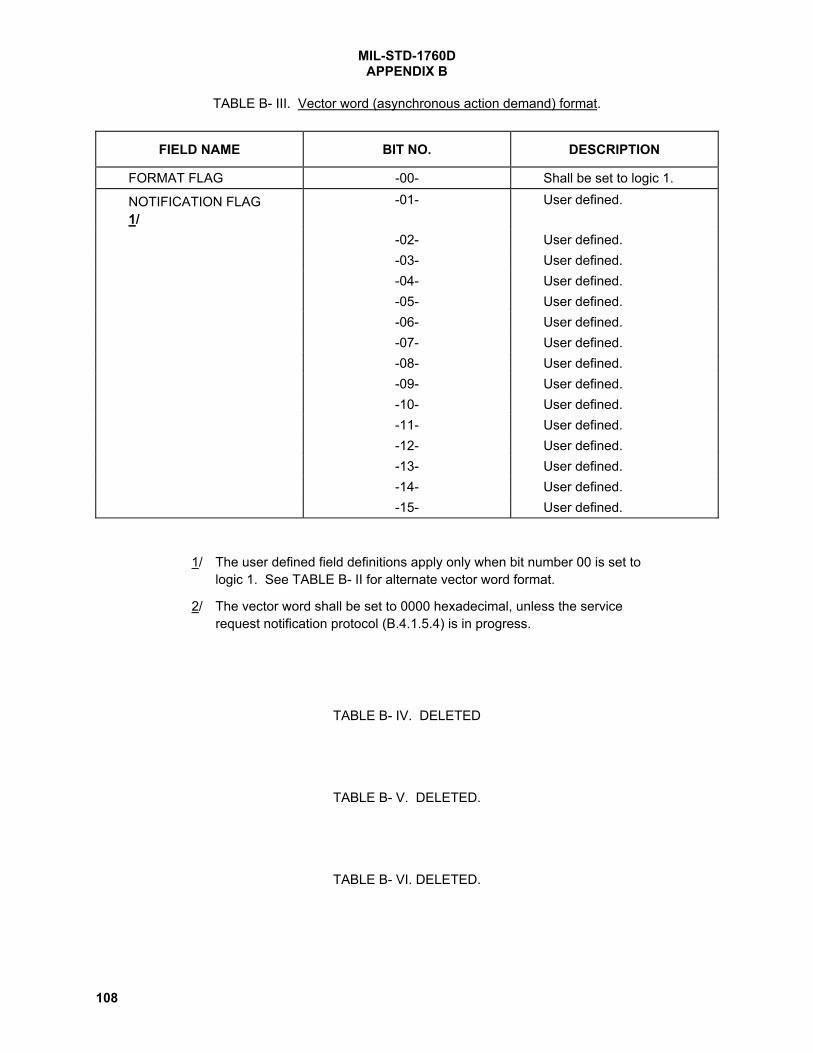
MIL-STD-1760DAPPENDIX B
108
TABLE B- III. Vector word (asynchronous action demand) format.
FIELD NAME BIT NO. DESCRIPTION
FORMAT FLAG -00- Shall be set to logic 1.
NOTIFICATION FLAG1/
-01- User defined.
-02- User defined.-03- User defined.-04- User defined.-05- User defined.-06- User defined.-07- User defined.-08- User defined.-09- User defined.-10- User defined.-11- User defined.-12- User defined.-13- User defined.-14- User defined.-15- User defined.
1/ The user defined field definitions apply only when bit number 00 is set tologic 1. See TABLE B- II for alternate vector word format.
2/ The vector word shall be set to 0000 hexadecimal, unless the servicerequest notification protocol (B.4.1.5.4) is in progress.
TABLE B- IV. DELETED
TABLE B- V. DELETED.
TABLE B- VI. DELETED.

MIL-STD-1760DAPPENDIX B
109
TABLE B- VII. Base message format (BC-RT transfer).
WORD NO. DESCRIPTION/COMMENT PARAGRAPH
-CW- COMMAND WORD (RECEIVE) B.4.1.1-01- HEADER B.4.2.1.1-02--03--04--05--06--07--08--09--10--11--12--13--14--15- Word positions for user selected data-16- entities and message checksum. B.4.2.1.2-17--18--19--20--21--22--23--24--25--26--27--28--29--30--SW- STATUS WORD (RECEIVER) B.4.1.2
1/ The format shown is for mission store messages. For carriage stores,however, words 31 and 32 may be added to the block referenced toparagraph B.4.2.1.2.

MIL-STD-1760DAPPENDIX B
110
TABLE B- VIII. Base message format (RT-BC transfer).
WORD NO. DESCRIPTION/COMMENT PARAGRAPH
-CW- COMMAND WORD (TRANSMIT) B.4.1.1
-SW- STATUS WORD (TRANSMITTER) B.4.1.2-01- HEADER B.4.2.1.1-02--03--04--05--06--07--08--09--10--11--12--13--14--15- Word positions for user selected data .-16- entities and message checksum B.4.2.1.2-17--18--19--20--21--22--23--24--25--26--27--28--29--30-
1/ The format shown is for mission store messages. For carriage stores,however, words 31 and 32 may be added to the block referenced toparagraph B.4.2.1.2.

MIL-STD-1760DAPPENDIX B
111
TABLE B- IX. Base message format (RT-RT transfer).
WORD NO. DESCRIPTION/COMMENT PARAGRAPH
-CW- COMMAND WORD (RECEIVE) B.4.1.1-CW- COMMAND WORD (TRANSMIT) B.4.1.1-SW- STATUS WORD (TRANSMITTER) B.4.1.2-01- HEADER B.4.2.1.1-02--03--04--05--06--07--08--09--10--11--12--13--14--15- Word positions for user selected data-16- entities and message checksum. B.4.2.1.2-17--18--19--20--21--22--23--24--25--26--27--28--29--30--SW- STATUS WORD (RECEIVER) B.4.1.2
1/ The format shown is for mission store messages. For carriage stores, however,words 31 and 32 may be added to the block referenced to paragraph B.4.2.1.2.

MIL-STD-1760DAPPENDIX B
112
TABLE B- X. Header word.
HEADER(HEXADECIMAL) APPLICATION
0000THROUGH User selected03FF0400 Store control message (B.4.2.2.1)0401THROUGH Reserved for store safety critical control and monitor041F0420 Store monitor message (B.4.2.2.2)0421 Store description message (B.4.2.2.3)0422 Transfer control message (B.4.2.3.2.1)0423 Transfer monitor message (B.4.2.3.2.2)0424THROUGH Reserved for carriage store non-safety critical control and monitor042D042ETHROUGH Reserved for future non-safety critical control and monitor04FF0500THROUGH User selectedFFFF
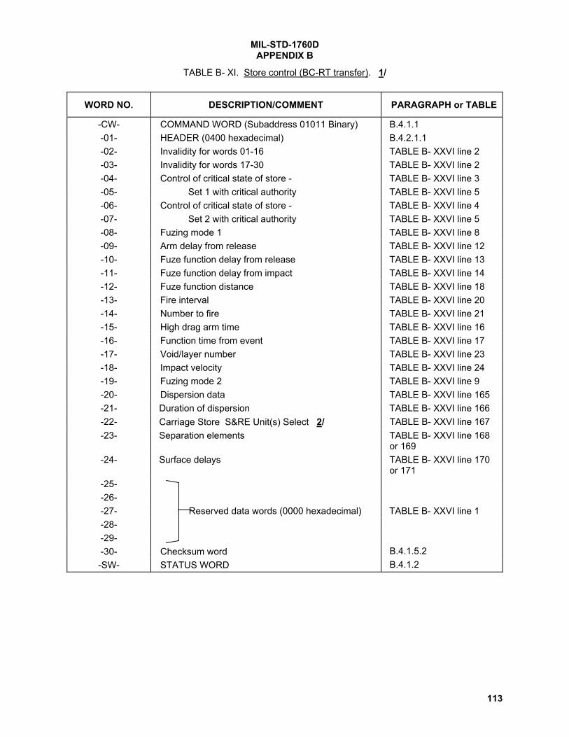
MIL-STD-1760DAPPENDIX B
113
TABLE B- XI. Store control (BC-RT transfer). 1/
WORD NO. DESCRIPTION/COMMENT PARAGRAPH or TABLE
-CW- COMMAND WORD (Subaddress 01011 Binary) B.4.1.1-01- HEADER (0400 hexadecimal) B.4.2.1.1-02- Invalidity for words 01-16 TABLE B- XXVI line 2-03- Invalidity for words 17-30 TABLE B- XXVI line 2-04- Control of critical state of store - TABLE B- XXVI line 3-05- Set 1 with critical authority TABLE B- XXVI line 5-06- Control of critical state of store - TABLE B- XXVI line 4-07- Set 2 with critical authority TABLE B- XXVI line 5-08- Fuzing mode 1 TABLE B- XXVI line 8-09- Arm delay from release TABLE B- XXVI line 12-10- Fuze function delay from release TABLE B- XXVI line 13-11- Fuze function delay from impact TABLE B- XXVI line 14-12- Fuze function distance TABLE B- XXVI line 18-13- Fire interval TABLE B- XXVI line 20-14- Number to fire TABLE B- XXVI line 21-15- High drag arm time TABLE B- XXVI line 16-16- Function time from event TABLE B- XXVI line 17-17- Void/layer number TABLE B- XXVI line 23-18- Impact velocity TABLE B- XXVI line 24-19- Fuzing mode 2 TABLE B- XXVI line 9-20- Dispersion data TABLE B- XXVI line 165-21- Duration of dispersion TABLE B- XXVI line 166-22- Carriage Store S&RE Unit(s) Select 2/ TABLE B- XXVI line 167-23- Separation elements TABLE B- XXVI line 168
or 169-24- Surface delays TABLE B- XXVI line 170
or 171-25--26--27- Reserved data words (0000 hexadecimal) TABLE B- XXVI line 1-28--29--30- Checksum word B.4.1.5.2-SW- STATUS WORD B.4.1.2

MIL-STD-1760DAPPENDIX B
114
TABLE B- XI. Store control (BC-RT transfer). (Continued)
1/ The message format shown is for BC-RT transfers. The data entities and entitysequence for word numbers 01 through 30 may also be applied to RT-RT transfersproviding that the transmitting RT is not an AEIS store.
2/ Word 22 to be used to identify the selected carriage store S&RE unit(s) when D10 (Bit00) of word 04 is set to logic 1 and D2 through D0 (Bits 08 through 10) are set to logic010 respectively.

MIL-STD-1760DAPPENDIX B
115
TABLE B- XII. Store monitor (RT-BC transfer). 1/
WORD NO. DESCRIPTION/COMMENT PARAGRAPH or TABLE
-CW- COMMAND WORD (Subaddress 01011Binary)
B.4.1.1
-SW- STATUS WORD B.4.1.2-01- HEADER (0420 hexadecimal) B.4.2.1.1-02- Invalidity for words 01-16 TABLE B- XXVI line 2-03- Invalidity for words 17-30 TABLE B- XXVI line 2-04- Critical monitor 1 TABLE B- XXVI line 6-05- Critical monitor 2 TABLE B- XXVI line 7-06- Fuzing/arming mode status 1 TABLE B- XXVI line 10-07- Protocol status TABLE B- XXVI line 25-08- Monitor of arm delay from release TABLE B- XXVI line 12-09- Monitor of fuze function delay from release TABLE B- XXVI line 13-10- Monitor of fuze function delay from impact TABLE B- XXVI line 14-11- Monitor of fuze function distance TABLE B- XXVI line 18-12- Monitor of fire interval TABLE B- XXVI line 20-13- Monitor of number to fire TABLE B- XXVI line 21-14- Monitor of high drag arm time TABLE B- XXVI line 16-15- Monitor of function time from event TABLE B- XXVI line 17-16- Monitor of void/layer number TABLE B- XXVI line 23-17- Monitor of impact velocity TABLE B- XXVI line 24-18- Fuzing/arming mode status 2 TABLE B- XXVI line 11-19- Monitor of dispersion data TABLE B- XXVI line 165-20- Monitor of dispersion duration TABLE B- XXVI line 166-21- Monitor of carriage store S&RE Unit(s) select TABLE B- XXVI line 167-22- Monitor of separation elements TABLE B- XXVI line 168
or 169-23- Monitor of surface delays TABLE B- XXVI line 170
or 171-24--25--26--27- Reserved words (0000 hexadecimal) TABLE B- XXVI line 1-28--29--30- Checksum word B.4.1.5.2
1/ The message format shown is for RT-BC transfers. The data entities and entitysequence for word numbers 01 through 30 may also be applied to RT-RTtransfers provided that the receiving RT is not an AEIS store.

MIL-STD-1760DAPPENDIX B
116
TABLE B- XIII. Store description message. 1/
WORD NO. DESCRIPTION/COMMENT PARAGRAPH orTABLE
-CW- COMMAND WORD (Subaddress 00001Binary)
B.4.1.1
-SW- STATUS WORD B.4.1.2-01- HEADER (0421 hexadecimal) B.4.2.1.1-02- Country code TABLE B- XXVI line 26-03- Store identity (binary) TABLE B- XXVI line 27-04- Store identity (ASCII) 1 TABLE B- XXVI line 28-05- Store identity (ASCII) 2 TABLE B- XXVI line 28-06- Store identity (ASCII) 3 TABLE B- XXVI line 28-07- Store identity (ASCII) 4 TABLE B- XXVI line 28-08- Store identity (ASCII) 5 TABLE B- XXVI line 28-09- Store identity (ASCII) 6 TABLE B- XXVI line 28-10- Store identity (ASCII) 7 TABLE B- XXVI line 28-11- Store identity (ASCII) 8 TABLE B- XXVI line 28-12- Maximum interruptive BIT time TABLE B- XXVI line 30-13- Store configuration identifier 1 TABLE B- XXVI line 29-14- Store configuration identifier 2 TABLE B- XXVI line 29-15- Store configuration identifier 3 TABLE B- XXVI line 29-16--17--18--19--20--21--22--23--24--25--26- Reserved words (0000 hexadecimal) TABLE B- XXVI line 1-27--28--29--30- Checksum word B.4.1.5.2.1
1/ The message format shown is for RT-BC transfers. The data entities and entitysequence for word numbers 01 through 30 may also be applied to RT-RT transfersproviding that the receiving RT is not an AEIS store.

MIL-STD-1760DAPPENDIX B
117
TABLE B- XIV. Country code.
FIELD NAME BIT NUMBER DESCRIPTION
CHARACTER 1 -00- (Shall be set to logic 0.)-01- High Order Bit-02--03--04--05--06--07- Low Order Bit
CHARACTER 2 -08- (Shall be set to logic 0.)-09- High Order Bit-10--11--12--13--14--15- Low Order Bit.
1/ The country code shall be represented by the character code set definedin ANSI X3.4 American Standard for Information Interchange (ASCII)using the appropriate country code specified in ISO 3166. (Only uppercase alphabetic characters shall be used.)
2/ Bit numbers 00 and 08 shall be set to logic 0.
3/ The country code shall be used as a qualifier of the store identity (binary)(TABLE B- XV) and store identity (ASCII) (TABLE B- XVI) to distinguishbetween store identification codes which may be duplicative betweendifferent countries.

MIL-STD-1760DAPPENDIX B
118
TABLE B- XV. Store identity (binary).
FIELD NAME BIT NUMBER DESCRIPTION
STORE TYPE -00- MSB = 1024-01--02--03- Shall be set to indicate the store
type code value as assigned bythe control point for storenomenclature.
-04--05--06--07--08--09--10- LSB = 1
STORE VARIANT -11- MSB = 16 Shall be set to indicate the storevariant code value as assignedby the control point for storenomenclature.
-12--13--14--15- LSB = 1
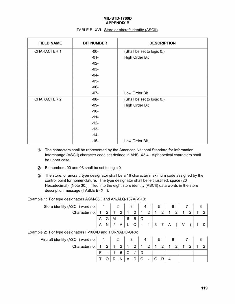
MIL-STD-1760DAPPENDIX B
119
TABLE B- XVI. Store or aircraft identity (ASCII).
FIELD NAME BIT NUMBER DESCRIPTION
CHARACTER 1 -00- (Shall be set to logic 0.)-01- High Order Bit-02--03--04--05--06--07- Low Order Bit
CHARACTER 2 -08- (Shall be set to logic 0.)-09- High Order Bit-10--11--12--13--14--15- Low Order Bit.
1/ The characters shall be represented by the American National Standard for InformationInterchange (ASCII) character code set defined in ANSI X3.4. Alphabetical characters shallbe upper case.
2/ Bit numbers 00 and 08 shall be set to logic 0.
3/ The store, or aircraft, type designator shall be a 16 character maximum code assigned by thecontrol point for nomenclature. The type designator shall be left justified, space (20Hexadecimal) [Note 30.] filled into the eight store identity (ASCII) data words in the storedescription message (TABLE B- XIII).
Example 1: For type designators AGM-65C and AN/ALQ-137A(V)10:
Store identity (ASCII) word no. 1 2 3 4 5 6 7 8Character no. 1 2 1 2 1 2 1 2 1 2 1 2 1 2 1 2
A G M - 6 5 CA N / A L Q - 1 3 7 A ( V ) 1 0
Example 2: For type designators F-16C/D and TORNADO-GR4:
Aircraft identity (ASCII) word no. 1 2 3 4 5 6 7 8
Character no. 1 2 1 2 1 2 1 2 1 2 1 2 1 2 1 2F - 1 6 C / DT O R N A D O - G R 4

MIL-STD-1760DAPPENDIX B
120
TABLE B- XVII. Transfer Control (TC) message format.
WORD NO. DESCRIPTION/COMMENT PARAGRAPH orTABLE
-CW- COMMAND WORD (Subaddress 01110binary)
B.4.1.1
-01- HEADER (0422 hexadecimal) B.4.2.1.1-02- Instruction B.4.2.3.2.1.2-03- Subaddress select B.4.2.3.2.1.3-04- File number B.4.2.3.2.1.4-05- Record number B.4.2.3.2.1.5-06- Block number B.4.2.3.2.1.6-07- File/record checksum B.4.2.3.2.1.7-08- Checksum word B.4.2.3.2.1.8-SW- STATUS WORD B.4.1.2

MIL-STD-1760DAPPENDIX B
121
TABLE B- XVIII. Instruction word.
FIELD NAME BIT NUMBER DESCRIPTION
INSTRUCTION TYPE -00- No operation - commands the store to updatethe TM message with current status of the massdata transfer transactions
-01- Select download mode - commands the store toenter (or remain in) the download mass datatransfer mode.
-02- Select upload mode - commands the store toenter (or remain in) the upload mass datatransfer mode.
-03- Start new file/record - commands the store toprepare for receiving or transmitting, asapplicable, Transfer Data (TD) messages.
-04- Erase all files - commands the store to erasedata in all store contained memory addressesallocated to mass data transfer storage.
-05- Erase designated file - commands the store toerase the designated file.
-06- Erase designated record - commands the storeto erase the designated record.
-07- Select echo mode - commands the store toenter (or remain in) the TD echo mode.
-08- Calculate file checksum - commands the storeto run the file checksum test.
-09- Calculate record checksum - commands thestore to run the record checksum test.
-10- System start - system start command to thestore.
-11- Exit transfer mode - commands the store to exitthe mass data transfer mode.
-12- Select block checksum mode - commands thestore to interpret word 30 of the TD message asa message checksum (See B.4.1.5.2.1) if indownload mode, or to supply word 30 of the TDmessage as a message checksum if in theupload mode.
RESERVED -13- Shall be set to a Logic 0.-14- Shall be set to a Logic 0.-15- Shall be set to a Logic 0.

MIL-STD-1760DAPPENDIX B
122
TABLE B- XIX. Allowable instruction type field bit states. [Note 31.]
INSTRUCTION ALLOWABLE BIT COMBINATIONS
WORD BITNUMBER
BIT NAME 1 2 3 4 5 6 7 8 9 10 11 12 13 14
0 No operation 1 0 0 0 0 0 0 0 0 0 0 0 0 0
1 Select download mode X 1 1 1 1 1 1 1 0 0 0 0 0 0
2 Select upload mode X 0 0 0 0 0 0 0 1 1 1 1 0 0
3 Start new file/record X 0 1 0 0 0 0 0 0 1 0 0 0 0
4 Erase all files X 0 0 1 0 0 0 0 0 0 0 0 0 0
5 Erase designated file X 0 0 0 1 0 0 0 0 0 0 0 0 0
6 Erase designatedrecord
X 0 0 0 0 1 0 0 0 0 0 0 0 0
7 Select echo mode X X Y X X X X X 0 0 0 0 0 0
8 Calculate file checksum X 0 0 0 0 0 1 0 0 0 1 0 0 0
9 Calculate recordchecksum
X 0 0 0 0 0 0 1 0 0 0 1 0 0
10 System start X 0 0 0 0 0 0 0 0 0 0 0 1 0
11 Exit transfer X 0 0 0 0 0 0 0 0 0 0 0 1 1
12 Select block checksummode
X X Y X X X X X X Y X X X X
1/ The Table represents the 14 allowable bit combinations of the 12 bitinstruction type field of TABLE B- XVIII.
2/ X = Don't care.
3/ Y = selectable option.

MIL-STD-1760DAPPENDIX B
123
TABLE B- XX. Subaddress select.
FIELD NAME BIT NUMBER DESCRIPTIONSUBADDRESS -00- MSB = 16 Subaddress of TD
message for designatedfile, record or block.
-01--02--03--04- LSB = 1
RESERVED -05--06--07--08--09- Shall be set to Logic 0.-10--11--12--13--14--15-
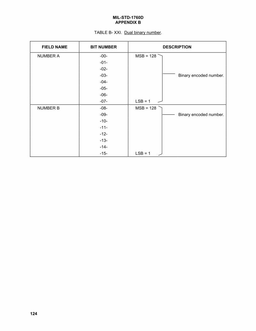
MIL-STD-1760DAPPENDIX B
124
TABLE B- XXI. Dual binary number.
FIELD NAME BIT NUMBER DESCRIPTION
NUMBER A -00- MSB = 128-01--02--03- Binary encoded number.-04--05--06--07- LSB = 1
NUMBER B -08- MSB = 128-09- Binary encoded number.-10--11--12--13--14--15- LSB = 1

MIL-STD-1760DAPPENDIX B
125
TABLE B- XXII. Transfer Monitor (TM) message format.
WORD NO. DESCRIPTION/COMMENT PARAGRAPH
-CW- COMMAND WORD (Subaddress 01110binary)
B.4.1.1
-SW- STATUS WORD B.4.1.2-01- HEADER (0423 hexadecimal) B.4.2.1.1-02- Last received instruction B.4.2.3.2.2.2-03- Transfer mode status B.4.2.3.2.2.3-04- Current selected subaddress B.4.2.3.2.2.4-05- Current file number B.4.2.3.2.2.5-06- Current record number B.4.2.3.2.2.6-07- Current block number B.4.2.3.2.2.7-08- Current file/record checksum B.4.2.3.2.2.8-09- Checksum word position B.4.2.3.2.2.9

MIL-STD-1760DAPPENDIX B
126
TABLE B- XXIII. Transfer mode status.
FIELD NAME BIT NUMBER DESCRIPTION
MODE STATUS -00- In download mode - indicates the store is indownload mode.
-01- In upload mode - indicates the store is inupload mode.
-02- Transfer enabled - indicates the store is readyfor transfer of TD messages
-03- Erase in progress - indicates the store iserasing the commanded MDT data
-04- Erase completed - indicates the store hascompleted the commanded erase operation.
-05- Echo mode selected - indicates echo mode isenabled in the store.
-06- Checksum calculation in progress - indicatesthe store is executing the commandedchecksum calculation.
-07- Checksum calculation completed - indicatesthe store has completed the commandedchecksum calculation.
-08- Checksum failed - indicates the commandedchecksum calculation failed.
-09- Execution started - indicates the store hasinitiated execution at the commanded locationor the mission store has loaded the location inthe TM message that the aircraft is to initiateexecution.
-10- Exit in progress - indicates the store is exitingthe MDT mode.
-11- Retransmission request - indicates the storerequest for retransmission of limited TD data
RESERVED -12- Shall be set to a Logic 0.-13- Shall be set to a Logic 0.-14- Shall be set to a Logic 0.-15- Shall be set to a Logic 0.

MIL-STD-1760DAPPENDIX B
127
TABLE B- XXIV. Transfer Data (TD) message format. 1/
WORD NO. DESCRIPTION/COMMENT PARAGRAPH
-CW- COMMAND WORD (Subaddress A/R) B.4.1.1-01- Record/block number B.4.2.3.2.3.1-02--03--04--05--06--07--08--09--10--11--12--13--14--15- File data-16--17--18--19--20--21--22--23--24--25--26--27--28--29--30--SW- STATUS WORD B.4.1.2
1/ This is a 30 word fixed length message.

MIL-STD-1760DAPPENDIX B
128
TABLE B- XXV. Allowable mode status field bit states.
STATUS ALLOWABLE BIT COMBINATION NUMBERSWORD BITNUMBER BIT NAME 1 2 3 4 5 6 7 8 9 10 11 12 13 14 15 16
0 In download mode 1 1 1 1 1 1 1 1 0 0 0 0 0 0 Y 1
1 In upload mode 0 0 0 0 0 0 0 0 1 1 1 1 1 1 Y 0
2 Transfer enabled 0 1 0 0 0 0 0 0 0 1 0 0 0 0 0 0
3 Erase in progress 0 0 1 0 0 0 0 0 0 0 0 0 0 0 0 0
4 Erase completed 0 0 0 1 0 0 0 0 0 0 0 0 0 0 0 0
5 Echo mode selected X X X X X X X 0 0 0 0 0 0 0 0 0
6 Checksum calculationin progress
0 0 0 0 1 0 0 0 0 0 1 0 0 0 0 0
7 Checksum calculationcompleted
0 0 0 0 0 1 1 0 0 0 0 1 1 0 0 0
8 Checksum failed 0 0 0 0 0 0 1 0 0 0 0 0 1 0 0 0
9 Execution started 0 0 0 0 0 0 0 1 0 0 0 0 0 1 0 0
10 Exit in progress 0 0 0 0 0 0 0 0 0 0 0 0 0 0 1 0
11 Retransmissionrequest
0 0 0 0 0 0 0 0 0 0 0 0 0 0 0 1
1/ The Table represents the 16 allowable bit combinations of the 11 bitmode status field of TABLE B- XXIII.
2/ X = reflects the commanded state of Echo mode from the last TCmessage.
3/ Y= the commanded mode prior to exit.

MIL-STD-1760DAPPENDIX B
129
TABLE B- XXVI. Data entity list. [Note 32.]
Lineno.
Data entityname
Entity Type andTable number
Entity shall comply with the following requirementsand description:
1 Reserved Bit numbers 00-15 shall be set to logic 0. Shall beplaced in transmitted or received messages to providefixed message lengths while reserving data wordpositions for future AEIS applications.
2 Invalidity INVALIDITY,TABLE B- XXXI
Shall be used to indicate invalidity of data entities.
3 Criticalcontrol 1
CRITICALCONTROL 1,TABLE B- XXXII
Shall be used for sending safety critical controlcommands to a mission store.
4 Criticalcontrol 2
CRITICALCONTROL 2,TABLE B- XXXIII
Shall be used for sending safety critical controlcommands to a mission store.
5 Criticalauthority
CRITICALAUTHORITY,TABLE B- XXXIV
Shall be used as a coded check for CRITICALCONTROL 1 and CRITICAL CONTROL 2. Shall not beused for error correction.
6 Criticalmonitor 1
CRITICALMONITOR 1,TABLE B- XXXV
Shall be used to indicate both the demanded state(reflecting data bits D10 through D3 in CRITICALCONTROL 1) and the current store state.
7 Criticalmonitor 2
CRITICALMONITOR 2,TABLE B- XXXVI
Shall be used to indicate both the demanded state(reflecting data bits D10 through D3 in CRITICALCONTROL 2) and the current store state.
8 Fuzing mode 1 FUZING MODE,TABLE B-XXXVII
Shall be used by stores with interface controllable postrelease operation to enable or disable fuze modes.
9 Fuzing mode 2 FUZING MODE,TABLE B- XLIII
(for stores with interface controllable post releaseoperation) Enables or disables fuze modes asindicated in the table.
10 Fuzing/armingmode status 1
FUZING/ARMING MODESTATUS,TABLE B-XXXVIII
Shall be used by stores, when requested by the aircraft,to reflect the actual internal state of the fuzing/armingsetting(s) whether or not demanded by TABLE B-XXXVII.
11 Fuzing/armingmode status 2
FUZING/ARMING MODESTATUS,TABLE B- XLIV
(when requested by the aircraft) Actual internal state ofthe store’s fuzing/arming setting(s), whether or notdemanded by TABLE B- XLIII.
12 Arm delay fromrelease
TIME(F),TABLE B- XXVII
Shall be used by stores with interface controllablefuzing as the time delay from separation from theaircraft to fuze arming.

MIL-STD-1760DAPPENDIX B
130
TABLE B- XXVI. Data entity list. (Continued)
Lineno.
Data entityname
Entity Type andTable number
Entity shall comply with the followingrequirements and description:
13 Fuze functiondelay fromrelease
TIME(F),TABLE B- XXVII
Shall be used by stores with interface controllablefuzing as the time delay from separation from theaircraft to fuze function.
14 Fuze functiondelay from impact
TIME(F),TABLE B- XXVII
Shall be used by stores with interface controllablefuzing as the time delay from impact to fuze function.
15 Post launchoperation delayMSP and LSP
TIME(M) &TIME(L),TABLE B- XXVII
The delays required in operation of store assemblies,such as motor fire, flight control, etc. Shall not beused for fuzing/arming.
16 High drag armtime
TIME(F),TABLE B- XXVII
(for stores with interface controllable fuzing) Timedelay from store separation from the aircraft to fuzearming when store retardation is selected.
17 Function timefrom event
TIME(F),TABLE B- XXVII
(for stores with interface controllable fuzing) Timedelay from a specifically defined event to the functionof the fuze or store retard mechanism.
18 Fuze functiondistance
DISTANCE(F),TABLE B- XXVII
Shall be used by stores with interface controllablefuzing as the distance from the target required forfunction. When used for Fuze function height, itrepresents altitude or depth from local surfacerequired for function. For pressure activated sensors,a surface air pressure of 82 kilopascals shall beassumed.
19 deleted
20 Fire interval TIME(L),TABLE B- XXVII
Shall be used to set the time interval betweensuccessive releases, launches or firings of associatedmunitions or submunitions.
21 Number to fire NUMBER(L),TABLE B- XXVII
Shall be used to set the number of munitions orsubmunitions to be released or fired for each releaseor fire commanded by TABLE B- XXXII, bit number00.
22 Roundsremaining
NUMBER(L),TABLE B- XXVII
The number of submunitions or stores remainingwithin the store.
23 Void/layernumber
NUMBER(L),TABLE B- XXVII
(for stores with interface controllable fuzing)Void/layer number at which the fuze is to function.
24 Impact velocity VELOCITY(M),TABLE B- XXVII
Sets the impact velocity.
25 Protocol status PROTOCOLSTATUS,TABLE B-XXXIX
Shall be used to report data bus interface protocolerrors detected by the applicable subsystem. (SeeB.4.1.5.1.)

MIL-STD-1760DAPPENDIX B
131
TABLE B- XXVI. Data entity list. (Continued)
Lineno.
Data entityname
Entity Type andTable number
Entity shall comply with the followingrequirements and description:
26 Country code COUNTRYCODE,TABLE B- XIV
Shall use the appropriate country code specified inISO 3166, upper case alphabetic characters only.Shall be used as a qualifier of STORE IDENTITY(BINARY) and STORE IDENTITY (ASCII) todistinguish between store identities which may beduplicative between different countries.
27 Store identity(binary)
STORE IDENT-ITY (BINARY),TABLE B- XV
A binary code assigned by the control point for storenomenclature. When this entity is not used, the wordshall be set to 0000 hexadecimal.
28 Store or aircraftidentity (ASCII)
STORE ORAIRCRAFTIDENTITY(ASCII),TABLE B- XVI
A code assigned by the control point fornomenclature. It shall be left justified into the eightdata words (max. 16 characters) per TABLE B- XIII.Unused characters shall be set to ASCII space (20Hexadecimal). When this entity is not used, thewords shall be set to 0000 hexadecimal.
29 Storeconfigurationidentifier
ASCII PACKED,TABLE B- XL
Specific configuration information about a store, suchas the software version installed. It shall be leftjustified into the three data words (max. 6 characters)per TABLE B- XIII. Unused characters shall be set toASCII space (20 Hexadecimal). When this entity isnot used, the words shall be set to 0000hexadecimal.
30 Maximuminterruptive BITtime
TIME(F),TABLE B- XXVII
The maximum time duration the store may be non-operational while conducting interruptive Built-In-Test(BIT) commanded by the aircraft. If interruptive BITis not used by the store, the word shall be set to0000 hexadecimal.
31 ASCII characters ASCII PACKED,TABLE B- XL
Shall be used for the transfer of ASCII encodedcharacters on the data bus.
32 Indicatedairspeed MSP &LSP
VELOCITY(M) &VELOCITY(L),TABLE B- XXVII
Indicated airspeed of the aircraft, represented aspositive when the aircraft is traveling through staticair in the Xa direction defined in FIGURE B- 2.
33 True airspeedMSP & LSP
VELOCITY(M) &VELOCITY(L),TABLE B- XXVII
True airspeed of the aircraft, represented as positivewhen the aircraft is traveling through static air in theXa direction defined in FIGURE B- 2.
34 Calibratedairspeed MSP &LSP
VELOCITY(M) &VELOCITY(L),TABLE B- XXVII
Calibrated airspeed of the aircraft, represented aspositive with the aircraft traveling through static air inthe Xa direction defined in FIGURE B- 2.
35 Windspeed NorthMSP & LSP
VELOCITY(M) &VELOCITY(L),TABLE B- XXVII
Local windspeed with north defined as thecomponent measured relative to local surface in thenorth (N) axis as defined by FIGURE B- 3.
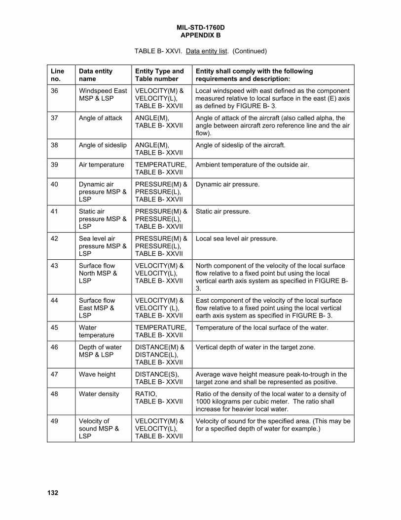
MIL-STD-1760DAPPENDIX B
132
TABLE B- XXVI. Data entity list. (Continued)
Lineno.
Data entityname
Entity Type andTable number
Entity shall comply with the followingrequirements and description:
36 Windspeed EastMSP & LSP
VELOCITY(M) &VELOCITY(L),TABLE B- XXVII
Local windspeed with east defined as the componentmeasured relative to local surface in the east (E) axisas defined by FIGURE B- 3.
37 Angle of attack ANGLE(M),TABLE B- XXVII
Angle of attack of the aircraft (also called alpha, theangle between aircraft zero reference line and the airflow).
38 Angle of sideslip ANGLE(M),TABLE B- XXVII
Angle of sideslip of the aircraft.
39 Air temperature TEMPERATURE,TABLE B- XXVII
Ambient temperature of the outside air.
40 Dynamic airpressure MSP &LSP
PRESSURE(M) &PRESSURE(L),TABLE B- XXVII
Dynamic air pressure.
41 Static airpressure MSP &LSP
PRESSURE(M) &PRESSURE(L),TABLE B- XXVII
Static air pressure.
42 Sea level airpressure MSP &LSP
PRESSURE(M) &PRESSURE(L),TABLE B- XXVII
Local sea level air pressure.
43 Surface flowNorth MSP &LSP
VELOCITY(M) &VELOCITY(L),TABLE B- XXVII
North component of the velocity of the local surfaceflow relative to a fixed point but using the localvertical earth axis system as specified in FIGURE B-3.
44 Surface flowEast MSP &LSP
VELOCITY(M) &VELOCITY (L),TABLE B- XXVII
East component of the velocity of the local surfaceflow relative to a fixed point using the local verticalearth axis system as specified in FIGURE B- 3.
45 Watertemperature
TEMPERATURE,TABLE B- XXVII
Temperature of the local surface of the water.
46 Depth of waterMSP & LSP
DISTANCE(M) &DISTANCE(L),TABLE B- XXVII
Vertical depth of water in the target zone.
47 Wave height DISTANCE(S),TABLE B- XXVII
Average wave height measure peak-to-trough in thetarget zone and shall be represented as positive.
48 Water density RATIO,TABLE B- XXVII
Ratio of the density of the local water to a density of1000 kilograms per cubic meter. The ratio shallincrease for heavier local water.
49 Velocity ofsound MSP &LSP
VELOCITY(M) &VELOCITY(L),TABLE B- XXVII
Velocity of sound for the specified area. (This may befor a specified depth of water for example.)

MIL-STD-1760DAPPENDIX B
133
TABLE B- XXVI. Data entity list. (Continued)
Lineno.
Data entityname
Entity Type andTable number
Entity shall comply with the followingrequirements and description:
50 Aircraft latitudeMSP & LSP
ANGLE(M) &ANGLE(L),TABLE B- XXVII
Geodetic latitude of the aircraft as defined inFIGURE B- 3.
51 Aircraftlongitude MSP &LSP
ANGLE(M) &ANGLE(L),TABLE B- XXVII
Geodetic longitude of the aircraft as defined inFIGURE B- 3.
52 Aircraft geodeticaltitude MSP &LSP
DISTANCE(M) &DISTANCE(L),TABLE B- XXVII
Geodetic altitude of the aircraft from the referenceellipsoid as defined in FIGURE B- 3.
53 Aircraft-fixedpoint distanceNorth MSP &LSP
DISTANCE(M) &DISTANCE(L),TABLE B- XXVII
North component (Na) of the current aircraft positiondisplacement from the fixed point as shown inFIGURE B- 4. The coordinate system shall be thelocal fixed point earth axis system defined inFIGURE B- 3.
54 Aircraft-fixedpoint distanceEast MSP &LSP
DISTANCE(M) &DISTANCE (L),TABLE B- XXVII
East component (Ea) of the current aircraft positiondisplacement from the fixed point as shown inFIGURE B- 4. Coordinate system shall be the localfixed point earth axis system defined in FIGURE B-3.
55 Aircraft-fixedpoint distancedown MSP &LSP
DISTANCE(M) &DISTANCE(L),TABLE B- XXVII
Down component (Da) of the current aircraft positiondisplacement from the fixed point as shown inFIGURE B- 4. Coordinate system shall be the localfixed point earth axis system defined in FIGURE B-3.
56 Height aboveground levelMSP & LSP
DISTANCE(M) &DISTANCE(L),TABLE B- XXVII
Height above ground level of the aircraft, defined asthe distance between the aircraft and the local earthsurface measured along the down (D) axis defined inFIGURE B- 3. The distance shall be represented aspositive.
57 Barometricaltitude MSP &LSP
DISTANCE(M) &DISTANCE(L),TABLE B- XXVII
Barometric altitude of the aircraft, defined as thedistance between the aircraft and the local earth sea-level measured along the down (D) axis defined inFIGURE B- 3. The distance shall be represented aspositive.
58 Aircraft trueheading
ANGLE(M),TABLE B- XXVII
Heading of the aircraft relative to true north asdefined in FIGURE B- 5 using the local vertical axisas defined in FIGURE B- 3.
59 Aircraft trueground track
ANGLE(M),TABLE B- XXVII
Ground track of the aircraft relative to true north asdefined in FIGURE B- 5 using the local vertical axisas defined in FIGURE B- 3.
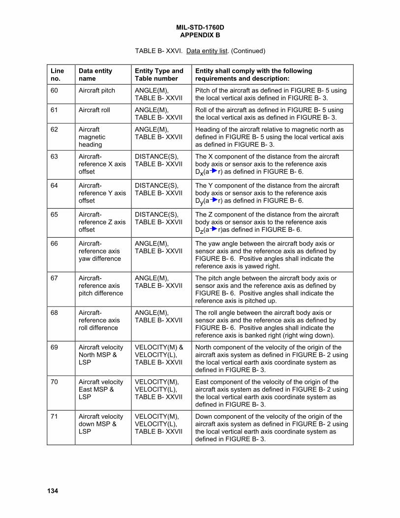
MIL-STD-1760DAPPENDIX B
134
TABLE B- XXVI. Data entity list. (Continued)
Lineno.
Data entityname
Entity Type andTable number
Entity shall comply with the followingrequirements and description:
60 Aircraft pitch ANGLE(M),TABLE B- XXVII
Pitch of the aircraft as defined in FIGURE B- 5 usingthe local vertical axis defined in FIGURE B- 3.
61 Aircraft roll ANGLE(M),TABLE B- XXVII
Roll of the aircraft as defined in FIGURE B- 5 usingthe local vertical axis as defined in FIGURE B- 3.
62 Aircraftmagneticheading
ANGLE(M),TABLE B- XXVII
Heading of the aircraft relative to magnetic north asdefined in FIGURE B- 5 using the local vertical axisas defined in FIGURE B- 3.
63 Aircraft-reference X axisoffset
DISTANCE(S),TABLE B- XXVII
The X component of the distance from the aircraftbody axis or sensor axis to the reference axisDx(a r) as defined in FIGURE B- 6.
64 Aircraft-reference Y axisoffset
DISTANCE(S),TABLE B- XXVII
The Y component of the distance from the aircraftbody axis or sensor axis to the reference axisDy(a r) as defined in FIGURE B- 6.
65 Aircraft-reference Z axisoffset
DISTANCE(S),TABLE B- XXVII
The Z component of the distance from the aircraftbody axis or sensor axis to the reference axisDz(a r)as defined in FIGURE B- 6.
66 Aircraft-reference axisyaw difference
ANGLE(M),TABLE B- XXVII
The yaw angle between the aircraft body axis orsensor axis and the reference axis as defined byFIGURE B- 6. Positive angles shall indicate thereference axis is yawed right.
67 Aircraft-reference axispitch difference
ANGLE(M),TABLE B- XXVII
The pitch angle between the aircraft body axis orsensor axis and the reference axis as defined byFIGURE B- 6. Positive angles shall indicate thereference axis is pitched up.
68 Aircraft-reference axisroll difference
ANGLE(M),TABLE B- XXVII
The roll angle between the aircraft body axis orsensor axis and the reference axis as defined byFIGURE B- 6. Positive angles shall indicate thereference axis is banked right (right wing down).
69 Aircraft velocityNorth MSP &LSP
VELOCITY(M) &VELOCITY(L),TABLE B- XXVII
North component of the velocity of the origin of theaircraft axis system as defined in FIGURE B- 2 usingthe local vertical earth axis coordinate system asdefined in FIGURE B- 3.
70 Aircraft velocityEast MSP &LSP
VELOCITY(M),VELOCITY(L),TABLE B- XXVII
East component of the velocity of the origin of theaircraft axis system as defined in FIGURE B- 2 usingthe local vertical earth axis coordinate system asdefined in FIGURE B- 3.
71 Aircraft velocitydown MSP &LSP
VELOCITY(M),VELOCITY(L),TABLE B- XXVII
Down component of the velocity of the origin of theaircraft axis system as defined in FIGURE B- 2 usingthe local vertical earth axis coordinate system asdefined in FIGURE B- 3.

MIL-STD-1760DAPPENDIX B
135
TABLE B- XXVI. Data entity list. (Continued)
Lineno.
Data entityname
Entity Type andTable number
Entity shall comply with the followingrequirements and description:
72 Aircraft headingrate
ANGULARRATE(M),TABLE B- XXVII
Rate of change of the information specified in line 58.
73 Aircraft groundtrack rate
ANGULARRATE(M),TABLE B- XXVII
Rate of change of the information specified in line 59.
74 Aircraft pitchrate
ANGULARRATE(M),TABLE B- XXVII
Rate of change of the information specified in line 60.
75 Aircraft roll rate ANGULARRATE(M),TABLE B- XXVII
Rate of change of the information specified in line 61.
76 Aircraft systemtime at reset
TIME(L)TABLE B- XXVII
Aircraft system time at the last reset of the aircraftsystem clock used by the aircraft as its reference fortime tagging data. Stores using time tagged datashall use this data in conjunction with present systemtime to determine the age of the time tagged data.
77 Mach number NUMBER(S),TABLE B- XXVII
Vehicle Mach number.
78 Direction cosineMSP & LSP
FRACTION(M),FRACTION(L),TABLE B- XXVII
A matrix element of a 3x3 transformation matrixbetween the aircraft and reference coordinatesystems in accordance with the following matrixequation: Xr = C * Xap; where C is the 3x3transformation matrix and both Xr and Xap arecolumn vectors as defined in FIGURE B- 6. Thequantity and identification of the matrix elements in Cand interpretation of the matrix equation shall bedefined in the store interface control document.
79 Initialization year NUMBER(L),TABLE B- XXVII
The current year.
80 Initializationmonth
NUMBER(L),TABLE B- XXVII
Current month of the current year as specified in line79.
81 Initialization dayof month
NUMBER(L),TABLE B- XXVII
Current day of the current month as specified in line80.
82 Initialization dayof year
NUMBER(L),TABLE B- XXVII
Current day of the current year as specified in line 79where January 1 is day 1.

MIL-STD-1760DAPPENDIX B
136
TABLE B- XXVI. Data entity list. (Continued)
Lineno.
Data entityname
Entity Type andTable number
Entity shall comply with the followingrequirements and description:
83 Twenty-fourhour period
NUMBER(L),TABLE B- XXVII
Used by aircraft or stores; the number of whole 24hour periods to, or from, the referenced event. It isused as required to compliment the time data entityin line 84..
84 Time MSP, LSP,& LLSP
TIME(M),TIME(L),TIME(LL),TABLE B- XXVII
Used by aircraft or stores; the time to, or from, thereferenced event.
85 Time tag TIME(L),TABLE B- XXVII
Inserted into the message by the source equipmentresponsible for the data entity(s) on which the timetag is to be used and shall be the aircraft time currentat the data measurement or event.
86 Aircraft time TIME(L),TABLE B- XXVII
Aircraft time to be transmitted to the store to allowbase time synchronization to take place. It shall bevalid at the zero crossing of the parity bit of theassociated command word received at the ASI, withthe tolerance specified in the ICD.
87 Representativegroup envelopedelay
TIME(LL),TABLE B- XXVII
Delay to a signal from the signal source to the signalsink.
88 Store repre-sentative groupenvelope delay
TIME(LL),TABLE B- XXVII
Delay to a signal from the signal source in the storeto the MSI or from the MSI to the signal sink in thestore.
89 Signal or datalatency MSP,LSP, & LLSP
TIME(M), TIME(L)& TIME(LL),TABLE B- XXVII
Latency of the signal or data during transfer betweena source and the MSI.
90 Signal or dataresponse timeMSP, LSP, &LLSP
TIME(M), TIME(L)& TIME(LL),TABLE B- XXVII
Time between the signal or data at an MSI and itsresultant response or event.
91 Signal or datadelay time MSP,LSP, & LLSP
TIME(M), TIME(L)& TIME(LL),TABLE B- XXVII
Delay caused to the signal or data during the transferbetween a sink and the source.
92 Target time MSP& LSP
TIME(M),TIME(L),TABLE B- XXVII
System time at the point in time when the targetposition is valid.
93 Waypointnumber of target
INTEGER,TABLE B- XXVII
Waypoint number, as specified in line 138, of thetarget position where a course to target trajectorydefined by waypoints is used.

MIL-STD-1760DAPPENDIX B
137
TABLE B- XXVI. Data entity list. (Continued)
Lineno.
Data entityname
Entity Type andTable number
Entity shall comply with the followingrequirements and description:
94 Target filenumber
NUMBER(L),TABLE B- XXVII
Indicates the selected target file.
95 Targetprobability
FRACTION(M),TABLE B- XXVII
Probability that the target can be successfullyintercepted by the store where all unknown factorsare assumed to not adversely affect the probability.
96 Targetdiscriminator
DISCRIMINATORDESCRIPTION,TABLE B- XLI
Indicates which of a group of targets shall beselected by terminal guidance.
97 Sea level airpressure at tar-get MSP & LSP
PRESSURE(M) &PRESSURE(L),TABLE B- XXVII
Sea-level referenced air pressure at the targetposition.
98 Current activetarget number
NUMBER(L),TABLE B- XXVII
Target number for which all information received bythe store applys, and which also is the preferredtarget once the store is released. Storesimplementing multiple targeting shall assume thatinformation received corresponds to the last targetnumber received.
99 Target invalidity INVALIDITY,TABLE B- XXXI
Validity for sixteen targets where valid (logic 0) shallequate to an available-for-use state.
100 Target latitudeMSP & LSP
ANGLE(M) &ANGLE(L),TABLE B- XXVII
Geodetic latitude of the target position as defined inFIGURE B- 3.
101 Target longitudeMSP & LSP
ANGLE(M) &ANGLE(L),TABLE B- XXVII
Geodetic longitude of the target position as definedin FIGURE B- 3.
102 Target geodeticaltitude MSP &LSP
DISTANCE(M) &DISTANCE(L),TABLE B- XXVII
Geodetic altitude of the target position from thereference ellipsoid as defined in FIGURE B- 3.
103 North targetdistance fromfixed point originMSP & LSP
DISTANCE(M) &DISTANCE(L),TABLE B- XXVII
North component (Nt) of the current target positiondisplacement from the fixed point as shown inFIGURE B- 4. The coordinate system shall be thelocal fixed point earth axis system defined inFIGURE B- 3.
104 East targetdistance fromfixed point originMSP & LSP
DISTANCE(M) &DISTANCE(L),TABLE B- XXVII
East component (Et) of the current target positiondisplacement from the fixed point as shown inFIGURE B- 4. The coordinate system shall be thelocal fixed point earth axis system defined inFIGURE B- 3.

MIL-STD-1760DAPPENDIX B
138
TABLE B- XXVI. Data entity list. (Continued)
Lineno.
Data entityname
Entity Type andTable number
Entity shall comply with the followingrequirements and description:
105 Target distancedown from fixedpoint origin MSP& LSP
DISTANCE(M) &DISTANCE(L),TABLE B- XXVII
Down component (Dt) of the current target positiondisplacement from the fixed point as shown inFIGURE B- 4. The coordinate system shall be thelocal fixed point earth axis system defined inFIGURE B- 3.
106 North targetdistance fromcurrent positionMSP & LSP
DISTANCE(M) &,DISTANCE(L),TABLE B- XXVII
North component (Nt) of the target positiondisplacement from the current aircraft position asshown in FIGURE B- 8. The coordinate system shallbe the local vertical earth axis system defined inFIGURE B- 3.
107 East targetdistance fromcurrent positionMSP & LSP
DISTANCE(M) &DISTANCE(L),TABLE B- XXVII
East component (Et) of the target position displace-ment from the current aircraft position as shown inFIGURE B- 8. The coordinate system shall be thelocal vertical earth axis system defined in FIGURE B-3.
108 Down targetdistance fromcurrent positionMSP & LSP
DISTANCE(M),DISTANCE(L),TABLE B- XXVII
Down component (Dt) of the target position displace-ment from the current aircraft position as shown inFIGURE B- 8. The coordinate system shall be thelocal vertical earth axis system defined in FIGURE B-3.
109 Target heightfrom surfaceMSP & LSP
DISTANCE(M) &DISTANCE(L),TABLE B- XXVII
Vertical displacement of the target position from thelocal surface level where negative values shallindicate that the position is sub-surface.
110 Target approachtrue heading
ANGLE(M),TABLE B- XXVII
True heading as defined in FIGURE B- 5 of the finalapproach course to the target position.
111 Target approachpitch
ANGLE(M),TABLE B- XXVII
Pitch as defined in FIGURE B- 5 of the finalapproach course to the target position.
112 Target azimuthto aircraft
ANGLE(M),TABLE B- XXVII
Target azimuth as shown in FIGURE B- 9 relative tothe aircraft axis system as shown in FIGURE B- 2.
113 Target elevationto aircraft
ANGLE(M),TABLE B- XXVII
Target elevation as shown in FIGURE B- 9 relative tothe aircraft axis system as shown in FIGURE B- 2.
114 Target slantrange (polarcoordinates)MSP & LSP
DISTANCE(M),DISTANCE(L),TABLE B- XXVII
Slant range distance, as shown in FIGURE B- 9,between the aircraft axis system origin, as shown inFIGURE B- 2, and the target center. The slant rangeshall be represented as positive.
115 Target azimuthto referencesystem
ANGLE(M),TABLE B- XXVII
Target azimuth as shown in FIGURE B- 9 relative tothe reference axis system as shown in FIGURE B- 6.
116 Target elevationto referencesystem
ANGLE(M),TABLE B- XXVII
Target elevation as shown in FIGURE B- 9 relative tothe reference axis system as shown in FIGURE B- 6.

MIL-STD-1760DAPPENDIX B
139
TABLE B- XXVI. Data entity list. (Continued)
Lineno.
Data entityname
Entity Type andTable number
Entity shall comply with the followingrequirements and description:
117 Target latituderate MSP & LSP
ANGULARRATE(M) &ANGULARRATE(L),TABLE B- XXVII
Rate of change of the information specified in line100.
118 Target longituderate MSP & LSP
ANGULARRATE(M) &ANGULARRATE(L),TABLE B- XXVII
Rate of change of the information specified in line101.
119 Target geodeticaltitude rate ofchange
VELOCITY(M),TABLE B- XXVII
Rate of change of the information specified in line102.
120 Target-fixedpoint distancenorth rate ofchange
VELOCITY(M),TABLE B- XXVII
Rate of change of the information specified in line103.
121 Target-fixedpoint distanceeast rate ofchange
VELOCITY(M),TABLE B- XXVII
Rate of change of the information specified in line104.
122 Target-fixedpoint distancedown rate ofchange
VELOCITY(M),TABLE B- XXVII
Rate of change of the information specified in line105.
123 Target-currentposition distanceNorth rate ofchange
VELOCITY(M),TABLE B- XXVII
Rate of change of the information specified in line106.
124 Target-currentposition distanceEast rate ofchange
VELOCITY(M),TABLE B- XXVII
Rate of change of the information specified in line107.
125 Target-currentposition distancedown rate ofchange
VELOCITY(M),TABLE B- XXVII
Rate of change of the information specified in line108.
126 Target azimuthrate to aircraft
ANGULARRATE(M),TABLE B- XXVII
Rate of change of the information specified in line112.

MIL-STD-1760DAPPENDIX B
140
TABLE B- XXVI. Data entity list. (Continued)
Lineno.
Data entityname
Entity Type andTable number
Entity shall comply with the followingrequirements and description:
127 Target elevationrate to aircraft
ANGULARRATE(M),TABLE B- XXVII
Rate of change of the information specified in line113.
128 Slant range rateof change
VELOCITY(M),TABLE B- XXVII
Rate of change of the information specified in line114. Negative slant range rate shall indicatedecreasing distance between aircraft and target.
129 Target azimuthrate to referencesystem
ANGULARRATE(M),TABLE B- XXVII
Rate of change of the information specified in line115.
130 Target elevationrate to referencesystem
ANGULARRATE(M),TABLE B- XXVII
Rate of change of the information specified in line116.
131 Emissionfrequency MSP,LSP & LLSP
FREQUENCY(M),FREQUENCY(L)&FREQUENCY(LL),TABLE B- XXVII
Frequency of the emission(s) of interest.
132 Emissionbandwidth MSP,LSP & LLSP
FREQUENCY(M),FREQUENCY(L) &FREQUENCY(LL),TABLE B- XXVII
Frequency bandwidth of the emission(s) of interest.
133 Emission PRFMSP & LSP
FREQUENCY(L) &FREQUENCY(LL),TABLE B- XXVII
Pulse repetition frequency of the emission(s) ofinterest.
134 Emissionpulsewidth MSP& LSP
TIME(L) &TIME(LL),TABLE B- XXVII
Pulsewidth of the emission(s) of interest.
135 Reference codefor emission
NUMBER(L),TABLE B- XXVII
Reference code for distinguishing between emitters.
136 Target altitudeMSP & LSP
DISTANCE(M) &DISTANCE(L),TABLE B- XXVII
Altitude of the target above mean sea level.
137 Time atwaypoint MSP,LSP & LLSP
TIME(M), TIME(L)& TIME(LL),TABLE B- XXVII
Time as specified in line 84 at the required point intime when the waypoint position is achieved.
138 Waypointnumber oftrajectory
INTEGER,TABLE B- XXVII
Waypoint number for the information in thesucceeding data words. Waypoint numbers shallincrease for successive points in the storetrajectory.

MIL-STD-1760DAPPENDIX B
141
TABLE B- XXVI. Data entity list. (Continued)
Lineno.
Data entityname
Entity Type andTable number
Entity shall comply with the followingrequirements and description:
139 Waypoint filenumber
NUMBER(L),TABLE B- XXVII
The selected waypoint file.
140 Sea level airpressure at way-point MSP & LSP
PRESSURE(M) &PRESSURE(L),TABLE B- XXVII
Sea-level referenced air pressure at the waypointposition.
141 Fire number ofstore
NUMBER(L),TABLE B- XXVII
Fire number, if implemented, shall be used bystores in free flight to distinguish themselves fromother stores in free flight.
142 Reference forcodedtransmission
NUMBER(L),TABLE B- XXVII
Reference code for coded transmissions to storesin free flight.
143 Guidancefrequency MSP &LSP
FREQUENCY(M) &FREQUENCY(L),TABLE B- XXVII
Frequency used for post release guidance.
144 Guidance bitlength MSP &LSP
TIME(L) &TIME(LL),TABLE B- XXVII
Length of time allocated to each data bit in postrelease guidance emission.
145 Guidance blocksize
NUMBER(L),TABLE B- XXVII
Number of data bits to be received in the first postrelease guidance transmission.
146 Waypoint latitudeMSP & LSP
ANGLE(M) &ANGLE(L),TABLE B- XXVII
Geodetic latitude of the waypoint position, wherelatitude is as defined in FIGURE B- 3.
147 Waypointlongitude MSP &LSP
ANGLE(M) &ANGLE(L),TABLE B- XXVII
Geodetic longitude of the waypoint position, wherelongitude is as defined in FIGURE B- 3.
148 Waypointgeodetic altitudeMSP & LSP
DISTANCE(M) &DISTANCE(L),TABLE B- XXVII
Geodetic altitude of the waypoint position from thereference ellipsoid as defined in FIGURE B- 3.
149 Waypoint-fixedpoint distancenorth MSP & LSP
DISTANCE(M) &DISTANCE(L),TABLE B- XXVII
North component (Nt) of the current waypointposition displacement from the fixed point asshown in FIGURE B- 4. The coordinate systemshall be the local fixed point earth axis system asdefined in FIGURE B- 3.
150 Waypoint-fixedpoint distanceeast MSP & LSP
DISTANCE(M) &DISTANCE(L),TABLE B- XXVII
East component (Et) of the current waypointposition displacement from the fixed point asshown in FIGURE B- 4. The coordinate systemshall be the local fixed point earth axis system asdefined in FIGURE B- 3.

MIL-STD-1760DAPPENDIX B
142
TABLE B- XXVI. Data entity list. (Continued)
Lineno.
Data entityname
Entity Type andTable number
Entity shall comply with the followingrequirements and description:
151 Waypoint-fixedpoint distancedown MSP & LSP
DISTANCE(M) &DISTANCE(L),TABLE B- XXVII
Down component (Dt) of the current waypoint positiondisplacement from the fixed point as shown inFIGURE B- 4. The coordinate system shall be thelocal fixed point earth axis system as defined inFIGURE B- 3.
152 Waypoint-currentposition northMSP & LSP
DISTANCE(M) &DISTANCE(L),TABLE B- XXVII
North component (Nt) of the waypoint position dis-placement from current aircraft position as shown inFIGURE B- 8. The coordinate system shall be thelocal vertical earth axis system defined in FIGURE B-3.
153 Waypoint-currentposition eastMSP & LSP
DISTANCE(M) &DISTANCE(L),TABLE B- XXVII
East component (Et) of the waypoint positiondisplacement from the current aircraft position asshown in FIGURE B- 8. The coordinate system shallbe the local vertical earth axis system defined inFIGURE B- 3.
154 Waypoint-currentposition downMSP & LSP
DISTANCE(M) &DISTANCE(L),TABLE B- XXVII
Down component (Dt) of the waypoint positiondisplacement from the current aircraft position asshown in FIGURE B- 8. The coordinate system shallbe the local vertical earth axis system defined inFIGURE B- 3.
155 Waypoint heightabove surfaceMSP & LSP
DISTANCE(M) &DISTANCE(L),TABLE B- XXVII
Vertical displacement of the waypoint position fromthe local surface level where negative values shallindicate that the position is subsurface.
156 Initial storecourse azimuth
ANGLE(M),TABLE B- XXVII
Azimuth of the initial store trajectory relative to thestore axis system as shown in FIGURE B- 7. Initialstore trajectory shall be as shown in FIGURE B- 9.
157 Initial storecourse elevation
ANGLE(M),TABLE B- XXVII
Elevation of the initial store trajectory relative to thestore axis system as shown in FIGURE B- 7. Initialstore trajectory shall be as shown in FIGURE B- 9.
158 Length of initialstore trajectoryMSP & LSP
DISTANCE(M) &DISTANCE(L),TABLE B- XXVII
Length of the initial store trajectory. The distanceshall be represented as positive.
159 Waypoint numberof launch point
INTEGER,TABLE B- XXVII
Waypoint number at which the store is intended to belaunched by the aircraft. The waypoint number shallbe as specified in line 138 where a course to targettrajectory defined by waypoints is used.
160 Launch pointlatitude MSP &LSP
ANGLE(M) &ANGLE(L),TABLE B- XXVII
Geodetic latitude of the store launch point position,where latitude is defined in FIGURE B- 3.

MIL-STD-1760DAPPENDIX B
143
TABLE B- XXVI. Data entity list. (Continued)
Lineno.
Data entityname
Entity Type andTable number
Entity shall comply with the followingrequirements and description:
161 Launch pointlongitude MSP &LSP
ANGLE(M) &ANGLE(L),TABLE B- XXVII
Geodetic longitude of the store launch point position,where longitude is defined in FIGURE B- 3.
162 Target area MSP& LSP
AREA(M) &AREA(L),TABLE B- XXVII
Area of the target.
163 Target dimension NUMBER(L)TABLE B- XXVII
Length and/or breadth of the target.
164 Time at first datalink messageMSP, LSP, LLSP
TIME(M),TIME(L),TIME(LL),TABLE B- XXVII
Time when the first data link message is passed.
165 Dispersion data DISPERSIONDATA,TABLE B- XLV
Store post-launch horizontal and vertical dispersionrequirements with respect to store boresight atlaunch.
166 Dispersionduration
TIME(L),TABLE B- XXVII
Duration of the store dispersion maneuver.
167 Carriage storeS&RE select
UNSIGNED,TABLE B- XXIX
Shall be used to indicate the carriage store S&REbeing controlled/monitored when fire is commandedby TABLE B- XXXII, bit number 00.
168 Separationduration
TIME,TABLE B- XLVIzone 1
Minimum time in seconds from detection of umbilicalseparation to execution of a dispersion maneuver orbeginning active guidance. Zone 2 of TABLE B- XLVIshall be zero filled.
169 Separationdistance
DISTANCE,TABLE B- XLVIzone 2
Minimum distance in meters to be achieved betweenaircraft and store before execution of a dispersionmaneuver or beginning active guidance. Distance iscalculated based on aircraft motion vector at time ofumbilical disconnect. Zone 1 of TABLE B- XLVI shallbe zero filled.
170 Surfacedeployment delay
TIME,TABLE B- XLVIzone 1
Minimum time in seconds from detection of umbilicalseparation to first movement of mission store controlsurfaces. If Surface deployment delay is not used,zone 2 of TABLE B- XLVI shall be zero filled.
171 Control surfaceunlock delay
TIME,TABLE B- XLVIzone 2
Minimum time in seconds from detection of umbilicalseparation to unlock of mission store control surfaces.If Control surface unlock delay is not used, zone 1 ofTABLE B- XLVI shall be zero filled.

MIL-STD-1760DAPPENDIX B
144
TABLE B- XXVI. Data entity list. (Continued)
Lineno.
Data entityname
Entity Type andTable number
Entity shall comply with the followingrequirements and description:
172 Store stationnumber
STORESTATIONNUMBERTABLE B-XLVIII,ZONE 1
Shall be used to indicate the store station number towhich the store is attached. It is to be used only inconjunction with line no. 28.
173 Pylon/Bay identity PYLON/BAYIDENTITYTABLE B-XLVIII,ZONE 2
Shall be used to indicate the pylon or bay to which thestore is attached. It is to be used only in conjunctionwith line no. 28

MIL-STD-1760DAPPENDIX B
145
TABLE B- XXVII. Linear data entities.
WORD TYPE FORMAT AS TABLE MSB VALUE LSB VALUETIME(M)(MICROSECONDS)
B-XXIX(UNSIGNED) 2
37
(1.37 x 10¹¹
)2
22
(4.19 x 10⁶
)TIME(L)(MICROSECONDS)
B-XXIX(UNSIGNED) 2
21
(2.1 x 10⁶
)2
6
(64)
TIME(LL)(MICROSECONDS)
B-XXIX(UNSIGNED) 2
5
(32)2
-10
(9.77 X 10⁻⁴
)TIME(F)(MICROSECONDS)
B-XXX(SCIENTIFIC) INTEGER:-(2
11 )(-2048)
EXPONENT: 168
INTEGER: 20(1)
EXPONENT: 160
FREQUENCY(M)(MHz)
B-XXIX(UNSIGNED) 2
24
(1.68 X 10⁷)
29
(512)
FREQUENCY(L)(MHz)
B-XXIX(UNSIGNED) 2
8
(256)2
-7
(7.8 X 10⁻³
)FREQUENCY (LL)(MHz)
B-XXIX(UNSIGNED) 2
-8
(3.9 X 10⁻³
)2
-23
(1.19 X 10⁻⁷
)DISTANCE(M)(METERS)
B-XXVIII(2's COMPLEMENT) -(2
24 )
(-1.68X10⁷)
29
(512)
DISTANCE(L)(METERS)
B-XXIX(UNSIGNED) 2
8
(256)2
-7
(7.8 x 10⁻³
)DISTANCE(S)(METERS)
B-XXVIII(2's COMPLEMENT) -(2
8 )
(-256)2
-7
(7.8 X 10⁻³
)DISTANCE(F)(METERS)
B-XXVIII(2's COMPLEMENT) -(2
14 )
(-16384)2
-1
(0.5)VELOCITY(M)(METERS/SECOND)
B-XXVIII(2's COMPLEMENT) -(2
13 )
(-8192)2
-2
(0.25)VELOCITY(L)(METERS/SECOND)
B-XXIX(UNSIGNED) 2
-3
(0.125)2
-18
(3.8 x 10⁻⁶
)ACCELERATION(M)(METERS/SECOND2)
B-XXVIII(2's COMPLEMENT) -(2
10 )
(-1024)2
-5
(3.1 x 10⁻²
)ACCELERATION(L)(METERS/SECOND2)
B-XXIX(UNSIGNED) 2
-6
(1.56 x 10⁻²
)2
-21
(4.77 x 10⁻⁷
)ANGLE(M)(SEMICIRCLES)
B-XXVIII(2's COMPLEMENT) -(2
0 )
(-1)2
-15
(3.05 x 10⁻⁵
)ANGLE(L)(SEMICIRCLES)
B-XXIX(UNSIGNED) 2
-16
(1.53 x 10⁻⁵
)
2-31
(4.66 x 10⁻¹⁰
)
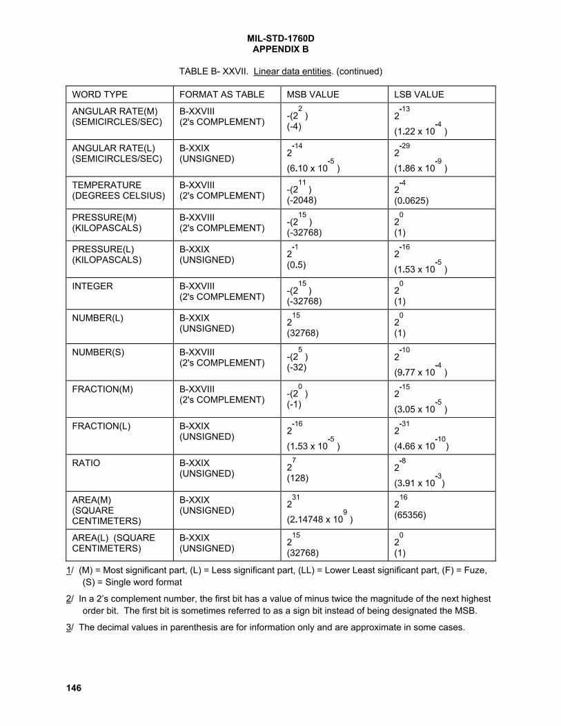
MIL-STD-1760DAPPENDIX B
146
TABLE B- XXVII. Linear data entities. (continued)
WORD TYPE FORMAT AS TABLE MSB VALUE LSB VALUE
ANGULAR RATE(M)(SEMICIRCLES/SEC)
B-XXVIII(2's COMPLEMENT) -(2
2 )
(-4)2
-13
(1.22 x 10⁻⁴
)
ANGULAR RATE(L)(SEMICIRCLES/SEC)
B-XXIX(UNSIGNED) 2
-14
(6.10 x 10⁻⁵
)2
-29
(1.86 x 10⁻⁹
)
TEMPERATURE(DEGREES CELSIUS)
B-XXVIII(2's COMPLEMENT) -(2
11 )
(-2048)2
-4
(0.0625)
PRESSURE(M)(KILOPASCALS)
B-XXVIII(2's COMPLEMENT) -(2
15 )
(-32768)2
0
(1)
PRESSURE(L)(KILOPASCALS)
B-XXIX(UNSIGNED) 2
-1
(0.5)2
-16
(1.53 x 10⁻⁵
)
INTEGER B-XXVIII(2's COMPLEMENT) -(2
15 )
(-32768)2
0
(1)
NUMBER(L) B-XXIX(UNSIGNED) 2
15
(32768)2
0
(1)
NUMBER(S) B-XXVIII(2's COMPLEMENT) -(2
5 )
(-32)2
-10
(9.77 x 10⁻⁴
)
FRACTION(M) B-XXVIII(2's COMPLEMENT) -(2
0 )
(-1)2
-15
(3.05 x 10⁻⁵
)
FRACTION(L) B-XXIX(UNSIGNED) 2
-16
(1.53 x 10⁻⁵
)2
-31
(4.66 x 10⁻¹⁰
)
RATIO B-XXIX(UNSIGNED) 2
7
(128)2
-8
(3.91 x 10⁻³
)
AREA(M)(SQUARECENTIMETERS)
B-XXIX(UNSIGNED) 2
31
(2.14748 x 10⁹ )
216
(65356)
AREA(L) (SQUARECENTIMETERS)
B-XXIX(UNSIGNED) 2
15
(32768)2
0
(1)
1/ (M) = Most significant part, (L) = Less significant part, (LL) = Lower Least significant part, (F) = Fuze,(S) = Single word format
2/ In a 2’s complement number, the first bit has a value of minus twice the magnitude of the next highestorder bit. The first bit is sometimes referred to as a sign bit instead of being designated the MSB.
3/ The decimal values in parenthesis are for information only and are approximate in some cases.

MIL-STD-1760DAPPENDIX B
147
TABLE B- XXVIII. 2's complement format.
FIELD NAME BIT NUMBER DESCRIPTION
MSB -00- MOST SIGNIFICANT DATA BIT
-01-
-02-
-03-
-04-
-05-
-06-
-07-
-08-
-09-
-10-
-11-
-12-
-13-
-14-
LSB -15- LEAST SIGNIFICANT DATA BIT
1/ Bit numbers 00 through 15 shall be encoded in 2's complement format.To obtain a negative of the number, all bits are inverted and one LSB isadded to the resulting number.
EXAMPLE: FFFF (hexadecimal) is the 2’s complement of 1 (decimal), andtherefore indicates -1 (decimal).
2/ The first bit of a two’s complement number (bit number 00) is sometimescalled the sign bit, as it was in MIL-HDBK-1553. This results in thesame bit pattern and is therefore functionally equivalent.

MIL-STD-1760DAPPENDIX B
148
TABLE B- XXIX. Unsigned format.
FIELD NAME BIT NUMBER DESCRIPTION
MSB -00- MOST SIGNIFICANT DATA BIT-01--02--03--04--05--06--07--08--09--10--11--12--13--14-
LSB -15- LEAST SIGNIFICANT DATA BIT
1/ For applications where an “unsigned" formatted data word is used as theleast significant part of a two word data parameter, this least significantword shall be encoded consistent with the encoding of the mostsignificant word in the set. If the most significant word is encoded as a2's complement, then this least significant word shall represent acontinuation of a 2's complemented value.
EXAMPLE: A/ Two word unsigned value:System time 6,400,000 (decimal) microseconds using TIME(M) and TIME(L) -
MSP = 0001 HexadecimalLSP = 86A0 Hexadecimal
EXAMPLE: B/ Two word signed value:Aircraft distance north of 1967 (decimal) meters using DISTANCE(M) and DISTANCE(L) -
MSP = 0003 HexadecimalLSP = D780 Hexadecimal
Aircraft distance north of -1967 (decimal) meters using DISTANCE(M) and DISTANCE(L) -
MSP = FFFC HexadecimalLSP = 2880 Hexadecimal

MIL-STD-1760DAPPENDIX B
149
TABLE B- XXX. Binary scientific notation format.
FIELD NAME BIT NUMBER DESCRIPTION
MSB -00- = -2048 UNITS
-01-
-02-
-03- 2's COMPLEMENT
-04- BINARY INTEGER
-05-
-06-
-07-
-08-
-09-
-10-
LSB -11- = 1 UNIT
EXPONENT MSB -12- = 8
-13- BINARY INTEGER
-14-
LSB -15- = 1
1/ The value represented by this format is given by:
(Integer) x 16(Exponent)
EXAMPLE: 0142 (hexadecimal) shall equate to 20 x 162 (decimal) or 5120 (decimal)

MIL-STD-1760DAPPENDIX B
150
TABLE B- XXXI. Invalidity word.
FIELD NAME BIT NUMBER DESCRIPTION
INVALIDITY -00- INVALIDITY OF WORD 1
-01- INVALIDITY OF WORD 2
-02- INVALIDITY OF WORD 3
-03- INVALIDITY OF WORD 4
-04- INVALIDITY OF WORD 5
-05- INVALIDITY OF WORD 6
-06- INVALIDITY OF WORD 7
-07- INVALIDITY OF WORD 8
-08- INVALIDITY OF WORD 9
-09- INVALIDITY OF WORD 10
-10- INVALIDITY OF WORD 11
-11- INVALIDITY OF WORD 12
-12- INVALIDITY OF WORD 13
-13- INVALIDITY OF WORD 14
-14- INVALIDITY OF WORD 15
-15- INVALIDITY OF WORD 16
1/ Invalidity bit set to logic 1 shall indicate that a word is invalid.
2/ For the standard message to/from subaddress 11, the invalidity bitsassociated with the reserved words and those associated with words thatare defined in the system specification or ICD as not used, shall be set tologic 0 (valid).
3/ For the standard message to/from subaddress 11, bits 00 through 15 inthe invalidity word shall indicate invalidity of words 1 through 16 in themessage and bits 00 through 15 in a second invalidity word shall indicatethe invalidity of words 17 through 32 in the message. Bits 14 and 15 inthe second word shall only be used during the routing of messageto/from a mission store carried on a carriage store and shall be set tologic 0 at all other times.
4/ For user defined messages, utilization and setting of the invalidity bitsshall be as defined in the system specification or ICD.

MIL-STD-1760DAPPENDIX B
151
TABLE B- XXXII. Critical control 1.
FIELD NAME BIT NUMBER DESCRIPTION
STORE CONTROL -00- D10 = Fire, Launch, or Release
1/ -01- D9 = Jettison
-02- D8 = Commit to Separate Store or Submunition
-03- D7 = Execute Arming
-04- D6 = Preset Arming
-05- D5 = Select Store
-06- D4 = Initiate Interruptive BIT
-07- D3 = Release/launch mode 12/
IDENTIFIER -08- D2
-09- D1 See 2/
-10- D0
ADDRESS CONFIRM -11- A4 Shall be set to match the logic state of the
-12- A3 corresponding interface address discrete
-13- A2 lines A4 through A0 as specified in 5.1.6
-14- A1 and 5.2.6.
-15- A0
1/ Data bits set to a logic 0 shall indicate that the associated function isrequired to be inactive. Data bits set to a logic 1 shall indicate that theassociated function is required to be active. Data bits reset to a logic 0shall indicate that the associated function is required to be deactivatedas applicable.
2/ The IDENTIFIER FIELD shall be set as indicated below.
D2 D1 D0
0 0 0 RESERVED0 0 1 Mission Store0 1 0 Carriage Store0 1 1 RESERVED
thru1 1 1 RESERVED

MIL-STD-1760DAPPENDIX B
152
TABLE B- XXXII. Critical control 1. (Continued)
3/ Stores shall discard any message found to contain a critical control wordthat fails one or more of the protocol checks in B.4.1.5.1. Stores shallonly enable safety critical processes demanded by critical control wordswhich pass the protocol checks detailed in B.4.1.5.1.
4/ The probability of inadvertent generation of a valid critical control wordwith a valid critical authority word and with a data field requesting criticalaction shall not exceed 1 in 10
5 flight hours per data field combination.
5/ D10 when received set to logic 1 shall be used to initiate potentiallyirreversible firing (including processes such as lasing), launching orrelease processes. (See 5.2.4.)
6/ D9 when received set to a logic 1 shall be used by the store to initiatejettison processes.
7/ D8 when received set to a logic 1 shall be used to initiate potentiallyirreversible processes associated with arming or to prepare for a storeseparation demand. (See 5.2.4.)
8/ D7 when received set to a logic 1 shall be used to initiate reversiblearming or safety degradation processes.
9/ D6 when received set to a logic 1 shall be used to preset the armingprocesses or safety degradation processes.
10/ D5 when received set to a logic 1 shall be used to initiate store activity.
11/ D4 when received set to a logic 1 shall be used to initiate built-in-testprocesses that may interrupt store subsystem operation. The built-in-test shall not, however, prevent the store from communicating with theaircraft on the data bus interface while BIT is in process.
12/ The Release/launch mode field shall be set as follows:D3 set to logic 0 indicates mission store to be released from a rack.D3 set to logic 1 indicates mission store to be launched by forward
firing from a rail launcher.

MIL-STD-1760DAPPENDIX B
153
TABLE B- XXXIII. Critical control 2.
FIELD NAME BIT NUMBER DESCRIPTION
STORE CONTROL -00- D10 = Erase command/authority
1/ -01- D9 = RF jam command/authority
-02- D8 = RF emission activate command/authority
-03- D7 = RESERVED. Shall be set to logic 0.
-04- D6 = RESERVED. Shall be set to logic 0
-05- D5 = RESERVED. Shall be set to logic 0
-06- D4 = RESERVED. Shall be set to logic 0
-07- D3 = RESERVED. Shall be set to logic 0
IDENTIFIER -08- D2
-09- D1 See 2/
-10- D0
ADDRESS CONFIRM -11- A4 Shall be set to match the logic state of the
-12- A3 corresponding interface address discrete
-13- A2 lines A4 through A0 as specified in 5.1.6
-14- A1 and 5.2.6.
-15- A0
1/ Data bits set to a logic 0 shall indicate that the associated function is required to beinactive. Data bits set to a logic 1 shall indicate that the associated function is required tobe active. Data bits reset to a logic 0 shall indicate that the associated function isrequired to be deactivated as applicable.
2/ The IDENTIFIER FIELD shall be set as indicated below.
D2 D1 D0
0 0 0 RESERVED0 0 1 Mission Store0 1 0 Carriage Store0 1 1 RESERVED
thru1 1 1 RESERVED
3/ Stores shall discard any message found to contain a critical control word thatfails one or more of the protocol checks in paragraph B.4.1.4. Stores shall onlyenable safety critical processes demanded by critical control words which passthe protocol checks detailed in B.4.1.4.

MIL-STD-1760DAPPENDIX B
154
TABLE B- XXXIV. Critical authority.
FIELD NAME BIT NUMBER DESCRIPTION
CODED CHECK -00- C14 = D10 + D9 + D6 + D1 + D0
-01- C13 = D9 + D8 + D5 + D0
-02- C12 = D8 + D7 + D4
-03- C11 = D7 + D6 + D3
-04- C10 = D10 + D9 + D5 + D2 + D1 + D0
-05- C9 = D10 + D8 + D6 + D4
-06- C8 = D10 + D7 + D6 + D5 + D3 + D1 + D0
-07- C7 = D10 + D5 + D4 + D2 + D1
-08- C6 = D10 + D6 + D4 + D3
-09- C5 = D9 + D5 + D3 + D2
-10- C4 = D10 + D9 + D8 + D6 + D4 + D2 + D0
-11- C3 = D9 + D8 + D7 + D5 + D3 + D1
-12- C2 = D10 + D9 + D8 + D7 + D4 + D2 + D1
-13- C1 = D10 + D8 + D7 + D3
-14- C0 = D10 + D7 + D2 + D1 + D0
RESERVED -15- RESERVED. Shall be set to logic 0
1/ Coded check bits shall be generated using modulo 2 arithmetic.
2/ D0 through D10 refer to bits D0 through D10 as defined in TABLE B-XXXII and TABLE B- XXXIII, as applicable.
3/ The coded check bits are based on the BCH 31, 16, 3 polynomial:
X15
+ X11
+ X10
+ X9 + X
8 + X
7 + X
5 + X
3 + X
2 + X + 1
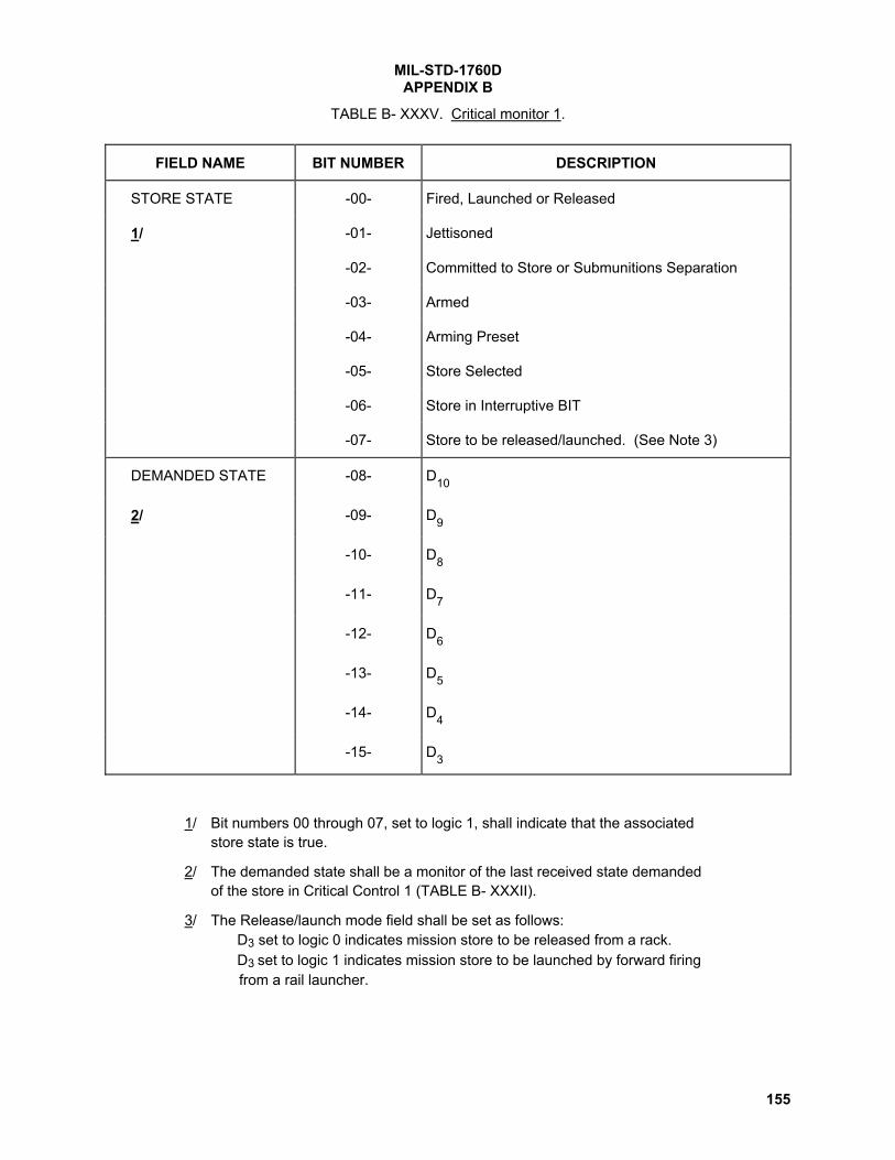
MIL-STD-1760DAPPENDIX B
155
TABLE B- XXXV. Critical monitor 1.
FIELD NAME BIT NUMBER DESCRIPTION
STORE STATE -00- Fired, Launched or Released
1/ -01- Jettisoned
-02- Committed to Store or Submunitions Separation
-03- Armed
-04- Arming Preset
-05- Store Selected
-06- Store in Interruptive BIT
-07- Store to be released/launched. (See Note 3)
DEMANDED STATE -08- D10
2/ -09- D9
-10- D8
-11- D7
-12- D6
-13- D5
-14- D4
-15- D3
1/ Bit numbers 00 through 07, set to logic 1, shall indicate that the associatedstore state is true.
2/ The demanded state shall be a monitor of the last received state demandedof the store in Critical Control 1 (TABLE B- XXXII).
3/ The Release/launch mode field shall be set as follows:D3 set to logic 0 indicates mission store to be released from a rack.D3 set to logic 1 indicates mission store to be launched by forward firing
from a rail launcher.

MIL-STD-1760DAPPENDIX B
156
TABLE B- XXXVI. Critical monitor 2.
FIELD NAME BIT NUMBER DESCRIPTION
STORE STATE -00- Erase on/authorized.
1/ -01- RF jam on/authorized.
-02- RF emission on/authorized.
-03- RESERVED. Shall be set to logic 0.
-04- RESERVED. Shall be set to logic 0.
-05- RESERVED. Shall be set to logic 0.
-06- RESERVED. Shall be set to logic 0.
-07- RESERVED. Shall be set to logic 0.
DEMANDED STATE -08- D10
2/ -09- D9
-10- D8
-11- D7
-12- D6
-13- D5
-14- D4
-15- D3
1/ Bit numbers 00 through 07, set to logic 1, shall indicate that the associatedstore state is true.
2/ The demanded state shall be a monitor of the last received state demandedof the store in Critical Control 2 (TABLE B- XXXIII).

MIL-STD-1760DAPPENDIX B
157
TABLE B- XXXVII. Fuzing mode 1.
FIELD NAME BIT NUMBER DESCRIPTION
FUZE CONTROL -00- D15 = Function at impact.
-01- D14 = Function on time after release 2/
-02- D13 = Function on time after impact 3/
-03- D12 = Function at altitude 4/
-04- D11 = Function at depth 4/
-05- D10 = Function on proximity 4/
-06- D9 = Function at position of target.
-07- D8 = Function on interference.
-08- D7 = Function on void 5/
-09- D6 = Function on layer 5/
-10- D5 = Low voltage detect.
-11- D4 = Long delay enable.
-12- D3 = Function at height 4/
-13- D2 = RESERVED. Shall be set to logic 0.
-14- D1 = RESERVED. Shall be set to logic 0.
-15- D0 = RESERVED. Shall be set to logic 0.
1/ Data bits set to a logic 1 shall indicate that the associated function is requiredto be active.
2/ The designated time is given in data word 10 of TABLE B- XI.
3/ The designated time is given in data word 11 of TABLE B- XI.
4/ The designated distance is given in data word 12 of TABLE B- XI.
5/ The designated number is given in data word 17 [Note 33.] of TABLE B- XI.

MIL-STD-1760DAPPENDIX B
158
TABLE B- XXXVIII. Fuzing/arming mode status 1.
FIELD NAME BIT NUMBER DESCRIPTION
STORE STATE -00- Function at impact is set.
-01- Function on time after release is set.
-02- Function on time after impact is set.
-03- Function at altitude is set.
-04- Function at depth is set.
-05- Function on proximity is set.
-06- Function at position of target is set.
-07- Function on interference is set.
-08- Function on void is set.
-09- Function on layer is set.
-10- Function on low voltage is set.
-11- Long delay is set.
-12- Function at height is set.
-13- RESERVED. Shall be set to logic 0.
-14- RESERVED. Shall be set to logic 0.
-15- RESERVED. Shall be set to logic 0.
1/ Bit numbers 00 through 15 of both Fuzing/arming mode status 1 andFuzing/arming mode status 2, all set to Logic 0, shall indicate that the storeis safe.
2/ Bit numbers 00 through 15, set to logic 1, shall indicate that the associatedstore state is true.

MIL-STD-1760DAPPENDIX B
159
TABLE B- XXXIX. Protocol status.
FIELD NAME BIT NUMBER DESCRIPTION
ERROR FLAG -00- Commanded word count not implemented.
1/ -01- Illegal header for commanded subaddress.
-02- Message checksum failure.
-03- Critical control/authority 1 failure.
-04- Critical control/authority 2 failure.
-05- RESERVED. Shall be set to logic 0.
-06- RESERVED. Shall be set to logic 0.
-07- RESERVED. Shall be set to logic 0.
-08- RESERVED. Shall be set to logic 0.
-09- RESERVED. Shall be set to logic 0.
-10- RESERVED. Shall be set to logic 0.
SUBADDRESS -11- MSB = 16
1/ -12- Subaddress of last erroneous
-13- message.
-14-
-15- LSB = 1
1/ Error flag data bit(s) set to logic 1 shall designate the error(s) detected in thelast erroneous message received by the subsystem. Bit numbers 11 through15 shall designate the subaddress of this last erroneous message.Subsequent receipt of an error-free message to this designated subaddressshall result in resetting of this data word to 0000 hexadecimal.

MIL-STD-1760DAPPENDIX B
160
TABLE B- XL. ASCII packed.
FIELD NAME BIT NUMBER DESCRIPTION
CHARACTER 11/
-00- (Shall be set to logic 0)
-01- High Order Bit
-02-
-03-
-04-
-05-
-06-
-07- Low Order Bit
CHARACTER 2 -08- (Shall be set to logic 0)
-09- High Order Bit
-10-
-11-
-12-
-13-
-14-
-15- Low Order Bit
1/ The characters shall be represented by the American National Standard forInformation Interchange (ASCII) character code set defined in ANSI X3.4.

MIL-STD-1760DAPPENDIX B
161
TABLE B- XLI. Discriminator description.
FIELD NAME BIT NUMBER DESCRIPTION
DISCRIMINATOR -00- Store should select target by position.ENABLES -01- Store should select target by size.1/ -02- Store should select targets by size and then target by
position.
TARGET -03- MSB = 8POSITIONIN GROUP -04- Indicates the sector (1 of 16) of the
pattern (FIGURE B- 10) in which the target(Operative when -05- is positioned. bit 00 or 02 = logic 1.) -06- LSB = 1
-07- MSB = 2 Indicates the segment (1 of 4) of the2/ pattern (FIGURE B- 10) in which the target
-08- LSB = 1 is positioned.
NUMBER OF -09- MSB = 8 Indicates the number of targets in the group.TARGETS IN -10- To be used in conjunction with bits 13-15GROUP -11- inclusive, when bit 01 = logic 1.
-12- LSB = 1
TARGET SIZE -13- MSB = 4 Shall indicate the number of the target whenIN GROUP the smallest = one.(Operative when bit 01 = logic 1.)
-14- Shall indicate the targets' size in the groupTARGET SIZE when the smallest = one.IN GROUP(Operative when bit 02 = logic 1.) -15- LSB = 1
1/ Data bits set to a logic 1 shall indicate that the associated function is true.
2/ FIGURE B- 10 illustrates the way in which this target position procedureshould be employed.
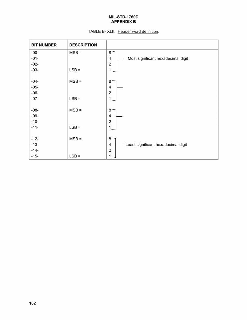
MIL-STD-1760DAPPENDIX B
162
TABLE B- XLII. Header word definition.
BIT NUMBER DESCRIPTION
-00- MSB = 8-01- 4 Most significant hexadecimal digit-02- 2-03- LSB = 1
-04- MSB = 8-05- 4-06- 2-07- LSB = 1
-08- MSB = 8-09- 4-10- 2-11- LSB = 1
-12- MSB = 8-13- 4 Least significant hexadecimal digit-14- 2-15- LSB = 1

MIL-STD-1760DAPPENDIX B
163
TABLE B- XLIII. Fuzing mode 2.
FIELD NAME BIT NUMBER DESCRIPTION
FUZE CONTROL1/
-00- D15 = RESERVED. Shall be set to logic 0.
-01- D14 = RESERVED. Shall be set to logic 0.
-02- D13 = RESERVED. Shall be set to logic 0.
-03- D12 = RESERVED. Shall be set to logic 0.
-04- D11 = RESERVED. Shall be set to logic 0.
-05- D10 = RESERVED. Shall be set to logic 0.
-06- D9 = RESERVED. Shall be set to logic 0.
-07- D8 = RESERVED. Shall be set to logic 0.
-08- D7 = Enable store retard mechanism. 2/
-09- D6 = Enable post release fuze control.
-10- D5 = RESERVED. Shall be set to logic 0.
-11- D4 = RESERVED. Shall be set to logic 0.
-12- D3 = RESERVED. Shall be set to logic 0.
-13- D2 = RESERVED. Shall be set to logic 0.
-14- D1 = RESERVED. Shall be set to logic 0.
-15- D0 = RESERVED. Shall be set to logic 0.
1/ Data bits set to a logic 1 shall indicate that the associated function is requiredto be active.
2/ Any designated time is given in data word 16 of TABLE B- XI.

MIL-STD-1760DAPPENDIX B
164
TABLE B- XLIV. Fuzing/arming mode status 2.
FIELD NAME BIT NUMBER DESCRIPTION
STORE STATE 1/ -00- RESERVED. Shall be set to logic 0.
-01- RESERVED. Shall be set to logic 0.
-02- RESERVED. Shall be set to logic 0.
-03- RESERVED. Shall be set to logic 0.
-04- RESERVED. Shall be set to logic 0.
-05- RESERVED. Shall be set to logic 0.
-06- RESERVED. Shall be set to logic 0.
-07- RESERVED. Shall be set to logic 0.
-08- Store retard mechanism is enabled
-09- Post release fuze control is enabled.
-10- RESERVED. Shall be set to logic 0.
-11- RESERVED. Shall be set to logic 0.
-12- RESERVED. Shall be set to logic 0.
-13- RESERVED. Shall be set to logic 0.
-14- RESERVED. Shall be set to logic 0.
-15- RESERVED. Shall be set to logic 0.
1/ Bit numbers 00 through 15 of both Fuzing/arming mode status 1 andFuzing/arming mode status 2, all set to Logic 0, shall indicate that the storeis safe.
2/ Bit numbers 00 through 15, set to Logic 1, shall indicate that the associatedstore state is true.

MIL-STD-1760DAPPENDIX B
165
TABLE B- XLV. Dispersion data word.
FIELD NAME BIT NUMBER DESCRIPTION
Horizontal dispersion -00- Left
1/ -01- Right
Horizontal dispersionangle
-02- MSB = 2-2
2/ -03-
-04-
-05- Horizontal dispersion angle
-06-
-07- LSB = 2-7
Vertical dispersion -08- Up
1/ -09- Down
Vertical dispersion angle -10- MSB = 2-2
3/ -11-
-12- Vertical dispersion angle
-13-
-14-
-15- LSB = 2-7
1/ One data bit only shall be set to indicate the associated dispersionrequirement. Neither data bit set shall indicate no dispersion requirement. Ifboth data bits are set the word shall be rejected. If dispersion is requestedwith the associated dispersion angle invalid then the word shall be rejected.
2/ An unsigned binary count of bits 02 to 07 shall be used in conjunction withbits 00 and 01 to specify the required horizontal angular dispersion insemicircles. All bits set at logic 0 or logic 1 shall signify an invalid dispersionangle. If an angular dispersion is defined in this field with no associatedhorizontal dispersion requirement then the word shall be rejected.
3/ An unsigned binary count of bits 10 to 15 shall be used in conjunction withbits 08 and 09 to specify the required vertical angular dispersion insemicircles. All bits set at logic 0 or 1 shall signify an invalid dispersionangle. If an angular dispersion is defined in this field with no associatedvertical dispersion requirement then the word shall be rejected.
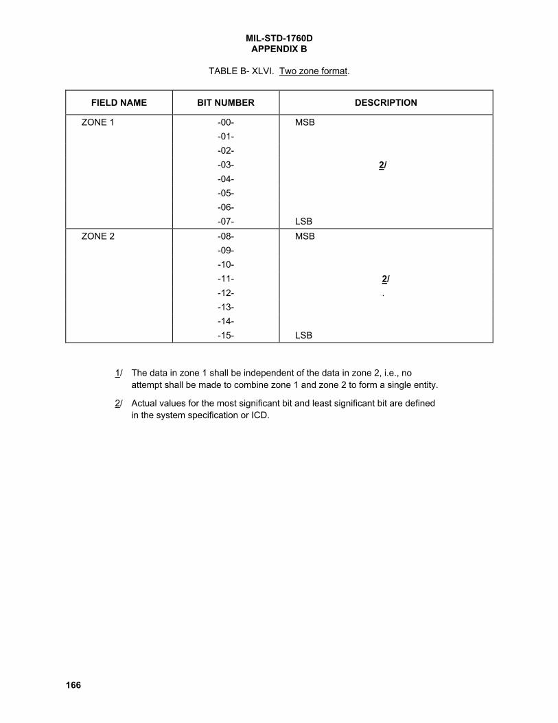
MIL-STD-1760DAPPENDIX B
166
TABLE B- XLVI. Two zone format.
FIELD NAME BIT NUMBER DESCRIPTION
ZONE 1 -00- MSB-01--02--03- 2/-04--05--06--07- LSB
ZONE 2 -08- MSB-09--10--11- 2/-12- .-13--14- -15- LSB
1/ The data in zone 1 shall be independent of the data in zone 2, i.e., noattempt shall be made to combine zone 1 and zone 2 to form a single entity.
2/ Actual values for the most significant bit and least significant bit are definedin the system specification or ICD.

MIL-STD-1760DAPPENDIX B
167
TABLE B- XLVII. Aircraft description message. 1/
WORD NO. DESCRIPTION/COMMENT PARAGRAPH orTABLE
-CW- COMMAND WORD (Subaddress 00001 Binary) B.4.1.1-01- HEADER (0421 hexadecimal) B.4.2.1.1-02- Invalidity for words 01-16 TABLE B- XXVI line 2-03- Invalidity for words 17-30 [Note 34.] TABLE B- XXVI line 2-04- Country code TABLE B- XXVI line 26-05- Aircraft identity (ASCII) 1 TABLE B- XXVI line 28-06- Aircraft identity (ASCII) 2 TABLE B- XXVI line 28-07- Aircraft identity (ASCII) 3 TABLE B- XXVI line 28-08- Aircraft identity (ASCII) 4 TABLE B- XXVI line 28-09- Aircraft identity (ASCII) 5 TABLE B- XXVI line 28-10- Aircraft identity (ASCII) 6 TABLE B- XXVI line 28-11- Aircraft identity (ASCII) 7 TABLE B- XXVI line 28-12- Aircraft identity (ASCII) 8 TABLE B- XXVI line 28-13- Station number and pylon/bay identity TABLE B- XXVI lines
172 & 173-14--15--16--17--18--19--20--21--22--23- Reserved words (0000 hexadecimal) TABLE B- XXVI line 1-24--25--26--27--28--29--30- Checksum word B.4.1.5.2.1-SW- STATUS WORD B.4.1.2
1/ The message format shown is for BC-RT transfers.

MIL-STD-1760DAPPENDIX B
168
TABLE B- XLVIII. Store station number and pylon/bay identity.
FIELD NAME BIT NUMBER DESCRIPTION
ZONE 1 -00- MSB = 128STORE STATION NUMBER -01-
-02--03--04--05--06--07- LSB = 1
ZONE 2 -08- Shall be set to logic 0PYLON/BAY IDENTITY -09- High Order Bit2/ -10-
-11--12- .-13--14--15- Low Order Bit
1/ Bit number 08 shall be set to logic 0.
2/ PYLON/BAY IDENTITY shall be represented by the ASCII character codeset defined in ANSI X3.4. Alphabetic characters shall be uppercase.

MIL-STD-1760DAPPENDIX C
169
ANNOTATIONS EXPLAINING DIFFERENCES FROM REVISION C NOTICE 1.
APPENDIX C
This listing is only a summary and does not include all changes. Note numbers in this listcorrespond to the [Note #] comments in the body of this document.
[Note 1.] The table of contents was revised as part of Revision D but changes are not marked.Page iii
[Note 2.] Specification and standards references were updated to recognize revised documentnumbers and incorporate references to sources for documents on the World Wide Web. Thenew documents are intended to be direct replacements for the old ones.Page 2
[Note 3.] The definition of Class II and Class IIA are changed in Rev D to be compatible withthe new 270 V dc power requirements.Pages 7, 155
[Note 4.] The asterisks were modified and a new footnote added to refer to the new 270 V dcpower requirements.Pages 9, 10
[Note 5.] The last sentence was replaced to clarify. No technical change was intended.Pages 13, 14
[Note 6.] New requirements on 270 V dc power were added. The SAE recommended changesincluded the statement: “If the aircraft is required to be compatible with pre MIL-STD-1760Dstores and stores implementing MIL-STD-1760D and up, it shall supply both 270 V dc and115/200 V ac power;” however, this would require future aircraft to have both sources, eventhough an aircraft with only 115 V ac would provide full compatibility. This issue is discussed inMIL-HDBK-1760, along with other issues of compatibility between versions of the standard.Pages 13, 14
[Note 7.] Notation was revised for clarity. No technical change was intended.Pages 17, 18
[Note 8.] Notation and wording of the notes was revised for clarity, but no technical changewas intended.Page 17
[Note 9.] Limits were extended to –400 ns and +400 ns, notation and wording of the notes wasrevised for clarity.Page 18

MIL-STD-1760DAPPENDIX C
170
[Note 10.] The break point at 625 kHz was at 1.25 MHz in Rev C. This change was made tobetter match the requirement to the performance of real systems.Page 21
[Note 11.] The data bus zero crossing deviation is changed to 120 ns. The old 150 nsrequirement (up through Rev B of the standard) was determined to be inappropriate, and therewere proposals to change it to 90 ns or 120 ns in Rev C. The standard was changed to 90 ns inRev C, but the handbook was written to reflect the rationale for 120 ns. This discrepancy wasreassessed in 2002 and it was determined that the 120 ns requirement is most appropriate.(See SAE AS-1B2 minutes for Sep 02).Page 24, 48
[Note 12.] The first sentence was re-worded to clarify the intent. A new requirement wasadded, limiting voltage drop while carrying rated current to 0.2 V. This was added to providespecific, measurable criteria for verifying structure ground integrity.Page 29
[Note 13.] The last sentence was deleted to eliminate reference to “valid” load conditions. Therequirement remains the same without this statement and deleting this statement eliminates theneed to define what loads are valid.Pages 30, 34
[Note 14.] This paragraph was reworded to eliminate references to “valid” load conditions andclarify. No change of the actual interface requirement was intended.Pages 30, 34, 34
[Note 15.] Figure 17 and 18 now have equations defining the curved portion of the maximumload current and maximum overcurrent limits. The actual limits on 28 V dc and 115 V ac currentdid not change.Pages 31, 32
[Note 16.] Figure was added as part of the new 270 V dc power requirements.Pages 31, 32
[Note 17.] New requirements on 270 V dc power were added in this paragraph andsubparagraphs.Pages 35, 44, 54
[Note 18.] New requirement on 270 V dc power was added. Original draft of Rev D required allthree supplies to be on, but it was later determined that 115 VAC and 270 VDC should never beapplied at the ASI simultaneously.Pages 37, 45, 55
[Note 19.] Paragraph was reworded to clarify the intent. A new requirement was added,limiting voltage drop while carrying rated current to 0.2 V. This was added to provide specific,measurable criteria for verifying structure ground integrity.Pages 41, 52
[Note 20.] Last sentence of paragraph 5.2.9.3 was deleted because it conflicts withrequirements of paragraph 5.2.9.9.Page 43

MIL-STD-1760DAPPENDIX C
171
[Note 21.] SAE AS-1B committee recommended this change to prohibit stores from connecting115 VAC power returns to ground in 1996.Page 43
[Note 22.] The first sentence of this paragraph was modified to incorporate new requirementson 270 V dc power.Pages 56, 56, 56
[Note 23.] Reworded to clarify use of dummy contacts.Page 57
[Note 24.] There were two paragraphs labeled “5.6.5” in Rev C of the standard. The second5.6.5 and subsequent paragraphs in this subsection have been renumbered.Page 57
[Note 25.] The footnote associated with contact location W on this table was changed to “5”.This resolves a discrepancy between MIL-STD-1760C and MIL-STD-1560 regarding thenumber of each contact type required. Also, ”Reserved” was removed from the 270 V dc powercontacts.Page 60
[Note 26.] MIL-C-39029 was added in the header to clarify.Page 61
[Note 27.] ”Reserved” was removed from the 270 V dc power contacts.Page 61
[Note 28.] Appendix A was added to define GPS RF requirements. It replaces the previouslyblank Appendix A.Page 65
[Note 29.] The store-to-aircraft part of time tagging is added in Rev D, to complement theaircraft-to-store part that was added in Rev C Notice 1.Page 78, 93, 93
[Note 30.] Table B-XVI, the word “blank” is replaced with the word “space,” since this is thecorrect term for the ASCII character often called “blank”. No technical change was intended.Page 119
[Note 31.] Table B-XIX, lines 7 and 12 were corrected.Page 122
[Note 32.] Table B-XXVI, entities 28 and 29, the word “blank” is replaced with the word “space”to use the correct term for this ASCII character.Page 129
[Note 33.] Table B-XXXVII , note 5 was changed to refer to word 17, to correct a typo.Page 157

MIL-STD-1760DAPPENDIX C
172
[Note 34.] Table B-XLVII, “invalidity for words 17-32” was changed to “invalidity for words 17-30” to correct a typo.Page 167

MIL-STD-1760D
173
CONCLUDING MATERIAL
Custodians: Preparing activity:Army - AV Air Force - 11Navy - ASAir Force - 11
Review activities: Project No. SESS-0044Navy - EC, SH, OS, MC, TD