Department of Computer Science and Engineering The...
107
Department of Computer Science and Engineering, CUHK 2004-2005 Final Year Project Report Department of Computer Science and Engineering The Chinese University of Hong Kong 2004/2005 Final Year Project First Term Report LYU 0404 Mobile Motion Tracking using Onboard Camera Supervisor Professor Michael R. Lyu Lam Man Kit Wong Yuk Man 1 December, 2004 LYU0404: Mobile Motion Tracking using Onboard Camera Page 1
Transcript of Department of Computer Science and Engineering The...

Department of Computer Science and Engineering, CUHK 2004-2005 Final Year Project Report
Department of Computer Science and Engineering
The Chinese University of Hong Kong
2004/2005 Final Year Project
First Term Report
LYU 0404
Mobile Motion Tracking using Onboard Camera
Supervisor
Professor Michael R. Lyu
Lam Man Kit
Wong Yuk Man
1 December, 2004
LYU0404: Mobile Motion Tracking using Onboard Camera Page 1

Department of Computer Science and Engineering, CUHK 2004-2005 Final Year Project Report
Abstract
This report describes the motivation, background information, experiments done and problem encountered by our group when participating in the final year project. The objective of our project is to use camera phone as an innovative input method for different applications on Symbian. Firstly, we will introduce the idea of our final year project – using motion tracking as an innovative input method. Following is the introduction of Symbian OS, the major operating system used in mobile phone nowadays, in the aspects of highlighted feature on how image manipulations can be done in Symbian phone. Next we will talk about the two testing platforms on PC and Symbian that we have developed. After that, we will discuss the common algorithms used in motion tracking and our proposed algorithms. These motion tracking algorithms would play an important role in our project.
Since we aim to develop a real-time motion tracking application on the mobile phone, both the speed and precision of algorithms are very important. The report will include the experimental results that we have done to evaluate the performance of different algorithms. Moreover, we performed investigations and experiments to find all possible ways so as to improve the accuracy and speed of the motion tracking.
Finally, we will describe the application that we have made and discuss what
other possible applications can be developed using our motion tracking algorithm.
LYU0404: Mobile Motion Tracking using Onboard Camera Page 2

Department of Computer Science and Engineering, CUHK 2004-2005 Final Year Project Report
Content Abstract.........................................................................................................................1 Chapter 1: Introduction ..............................................................................................7
1.1 Motivation............................................................................................................7 1.2 Programming Capability of Symbian-based Mobile Phone ................................8 1.3 Project Objective..................................................................................................8 1.4 Project Equipment................................................................................................9
Chapter 2: Symbian Operating System ...................................................................10 2.1 Development Environment ................................................................................11 2.2 Testing environment...........................................................................................12 2.3 Limitations in Symbian phone ...........................................................................12 2.4 Overview of Symbian Graphics Architecture ....................................................13
2.4.1 Video Capturing ..........................................................................................13 2.5 Why Programming in Symbian .........................................................................15 2.6 Conclusion .........................................................................................................16
Chapter3: OpenCV Testing Platform on Window..................................................17 3.1 OpenCV Library ................................................................................................17 3.2 OpenCV Testing Platform..................................................................................17 3.3 Static Frames Motion Tracking..........................................................................20 3.4 Real-Time Motion Tracking...............................................................................23
3.4.2 Difficulties on Real-time tracking ..............................................................24 3.4.3 Evaluate the Performance of Real-Time Motion Tracking.........................25 3.4.4 Relationship with Real-Time Camera Motion Tracking.............................26
3.5 Feature Selection................................................................................................27 Chapter 4: Testing Platform on Symbian ................................................................28
4.1 Introduction........................................................................................................28 4.2 User Interface.....................................................................................................28 4.3 Design and Implementation ...............................................................................30
4.3.1 Class Structure ............................................................................................30 4.3.2 Reserving Camera.......................................................................................32 4.3.3 Releasing Camera .......................................................................................34 4.3.4 Reset Contrast, Brightness and Exposure Mode of camera........................34 4.3.5 Running the Block Matching Algorithm.....................................................36
Chapter 5: Motion Tracking .....................................................................................38 5.1 Characterization of the motion...........................................................................38 5.2 Block-Matching Motion tracking ......................................................................39
LYU0404: Mobile Motion Tracking using Onboard Camera Page 3

Department of Computer Science and Engineering, CUHK 2004-2005 Final Year Project Report
5.2.1 Principle of Block-Matching Motion Tracking ..........................................39 5.2.2 Cost Functions ............................................................................................41 5.2.3 The Exhaustive Search Algorithm (SEA) ...................................................43 5.2.4 Fast Motion tracking Algorithms ................................................................44 ...............................................................455.2.4.1 Three-Step Search Algorithm .................................................................................465.2.4.2 Time Complexity ..................................................475.2.4.3 Problem of fast searching algorithms ...........................................................................................485.2.4.4 Conclusion
..............................................................485.2.5 Fast Exhaustive Search Algorithm ....................................485.2.5.1 The Successive Elimination Algorithm (SEA) ......................................495.2.5.2 PPNM (Progressive Partial Norm Matching)
5.3 Fast Calculation of Block Sum ..........................................................................50 5.3.1 Objective .....................................................................................................50 5.3.2 Methodology...............................................................................................51 5.3.3 Advantage to SEA and PPNM ....................................................................52 5.3.4 Disadvantage...............................................................................................53
5.4 Summary ............................................................................................................54 5.5 The Motion tracking Hypothesis .......................................................................54
5.5.1 The Motion tracking Assumptions..............................................................54 5.5.2 Proximity Translation..................................................................................55 5.5.3 Intensity Stability ........................................................................................55 5.5.4 Linear Motion Hypothesis ..........................................................................56
5.6 Optical Flow.......................................................................................................57 5.6.1 Overview of Optical Flow ..........................................................................57 5.6.2 Motion Fields ..............................................................................................57 5.6.3 Difference between Optical Flow and Motion Field ..................................58 5.6.4 Optical flow computation ...........................................................................59 5.6.5 Comparison between optical flow and block-matching..............................63 5.6.6 Conclusion ..................................................................................................64
5.7 Partial Distortion Elimination ............................................................................64 5.7.1 Methodology...............................................................................................65 5.7.2 Result ..........................................................................................................66 5.7.3 Possible Improvement.................................................................................66
5.8 Adaptive Search Window...................................................................................67 5.8.1 Methodology...............................................................................................68 5.8.2 Comparison with conventional method ......................................................69 5.8.3 Constraint of each method ..........................................................................72 5.8.4 Analysis.......................................................................................................73
LYU0404: Mobile Motion Tracking using Onboard Camera Page 4

Department of Computer Science and Engineering, CUHK 2004-2005 Final Year Project Report
5.8.5 Conclusion ..................................................................................................73 5.9 Spiral Scan Method............................................................................................74
5.9.1 Raster Scan method.....................................................................................74 5.9.2 Analysis.......................................................................................................74 5.9.3 Spiral Scan Method.....................................................................................75 5.9.4 Result ..........................................................................................................75
5.10 Motion Tracking Algorithm Development.......................................................76 Chapter 6: Feature Selection ....................................................................................78
6.1 Implementation ..................................................................................................78 6.2 Laplacian Operator.............................................................................................80 6.3 Experimental Result...........................................................................................81 6.4 Conclusion .........................................................................................................84
Chapter 7: Applications.............................................................................................85 7.1 Development procedure .....................................................................................85 7.2 Example Applications ........................................................................................86
7.2.1 Pong Game..................................................................................................87 7.2.2 Virtual Mouse..............................................................................................88
7.3 Other Possible Application ................................................................................88 7.3.1 Camera Mouse ............................................................................................88
Chapter 8: Experimental Result...............................................................................89 8.1 Computation load of SSD and SAD ..................................................................89 8.2 Improvement of ESA by SEA/PPNM................................................................91 8.3 Enhancement of SEA/PPNM by PDE ...............................................................91 8.4 Enhancement by Spiral Scan Method ................................................................93 8.5 Enhancement by Adaptive Spiral Method .........................................................94
Chapter 9: Project Progress......................................................................................97 Chapter ..........................................................................9910: Contribution of Work
10.1 Introduction......................................................................................................99 10.2 Preparation of Work .........................................................................................99 10.2 The Algorithm Part ........................................................................................100 10.3 The Testing Platform Part ..............................................................................100 10.4 The Application Part ......................................................................................101 10.5 Conclusion .....................................................................................................101
Chapter 11: Conclusion ...........................................................................................102 Chapter 12: Future Work........................................................................................103
12.1 Further Improve the Block Matching Algorithm by Hierarchical method ....103 12.2 Study and implement algorithms to detect rotation angle .............................103 12.3 Develop virtual mouse application ................................................................103
LYU0404: Mobile Motion Tracking using Onboard Camera Page 5

Department of Computer Science and Engineering, CUHK 2004-2005 Final Year Project Report
12.4 Develop Multiplayer Game............................................................................103 12.5 Develop other interesting applications...........................................................104 12.6 Build SDK......................................................................................................104
Chapter 13: Acknowledgement...............................................................................104 Chapter 14: Reference.............................................................................................105
LYU0404: Mobile Motion Tracking using Onboard Camera Page 6

Department of Computer Science and Engineering, CUHK 2004-2005 Final Year Project Report
Chapter 1: Introduction
1.1 Motivation
Nowadays, it seems as though everyone has a mobile phone. As models with integrated CCD cameras are getting more and more popular, camera-phones have become popular networked personal image capture devices. It not only acts as a digital camera, but also provides constant wireless connectivity that allows them to exchange photo or video they captured with their friends. 3G phones even use their capabilities to make video calls as their selling point. However, other than taking pictures and capturing video, is it possible to add more values to the camera and make full use of it? This is the motivation of our FYP project.
As camera resolution improves and computation power increases, camera-phones can do more interesting things than just taking pictures and sending them out over mobile phone network. Programmable camera-phones
LYU0404: Mobile Motion Tracking using Onboard Camera Page 7

Department of Computer Science and Engineering, CUHK 2004-2005 Final Year Project Report
can actually perform image processing tasks on the device itself. With the real-time video captured by the onboard camera, we can use this information to track the motion of the phone. The result of motion tracking can then be used as an additional and innovative mean of user input, and this is our main objective of the FYP project.
1.2 Programming Capability of Symbian-based Mobile Phone
In the past, normal users were difficult to develop programs on their mobile phones. Even though users could write J2ME programs on mobile phones, J2ME does not provide phone-specific API to access the camera. Nowadays, Symbian OS makes programming on camera-phone possible. Symbian-based mobile phones allow user programs to access most of the functions provided by the phones, including the camera functions and image manipulation functions. Some 3G phones are also Symbian-based. They also allow users to develop programs on them. As Symbian OS will be the major operating system for mobile devices in the foreseeing future and its programming capability, our FYP project will use Symbian as our target platform.
Our applications will be useful for any 2G, 2.5G or 3G Symbian-based mobile phones.
1.3 Project Objective
The goal of our FYP project is to implement a real-time motion-tracking algorithm in Symbian-based mobile phones and use the tracking result as an innovative mean of user input like mouse and keyboard input. The aim of motion-tracking is not to track objects behind the camera but to track the movement of the camera, or the equivalence - the phone. This new mean of user input can give user a convenient way to operate the phone and any wireless-connected devices. For example, the phone can be used as a virtual computer mouse that allow user to control the cursor in desktop computer as if he/she is using a wireless optical mouse. Other than using the buttons or the joystick on the mobile phone as input method, users have one more choice - “motion input”, provided that the phone is programmable and camera-integrated. Users can also pre-define some gestures so that moving the phone in certain ways will trigger some events, such as making a phone call to the others. It
LYU0404: Mobile Motion Tracking using Onboard Camera Page 8

Department of Computer Science and Engineering, CUHK 2004-2005 Final Year Project Report
saves time pressing buttons to dial the phone. A more interesting application is to use it as the input method for games. For example, in a racing motorcycle game, tilting the phone can be used to control the motorcycle to tilt left or tilt right while moving the phone vertically can control the speed of the motorcycle. Using motion input is so fun and exciting that users can interact with the game.
1.4 Project Equipment
Our project involves a Symbian mobile phone, Nokia 6600, which is equipped with Symbian OS 7.0 Series 60. Since the development cycle in Symbian mobile phone is quite long, we have decided to implement the real-time motion-tracking algorithm on PCs using web camera. Therefore, our project also involves web camera, Logitech QuickCam Pro 4000, as the video capturing device for the PCs.
Apart from Symbian based camera-phone, any other mobile devices that are
programmable and camera-integrated are also the target platforms of our project. Some of the Pocket PCs, for example, are camera-integrated and are all programmable. It is also possible to develop interesting applications or games on these platforms.
LYU0404: Mobile Motion Tracking using Onboard Camera Page 9

Department of Computer Science and Engineering, CUHK 2004-2005 Final Year Project Report
Chapter 2: Symbian Operating System
Symbian OS is the global industry standard operating system for smartphones. It is structured like many desktop operating systems, with pre-emptive multitasking, multithreading and memory protection.
Because of its robust multi-tasking kernel, communications protocols (e.g. WAP and Bluetooth), data management, advanced graphics support (support of direct-access and common hardware accelerator), Symbian OS has become the major operating system for current generation of mobile phones.
In short, the functionalities of Symbian phone are summarized in the following
diagram:
Figure 2.1 Symbian 7.0 architecture
The main focus of this chapter is to illustrate how Symbian OS provides support on image process in the phones and how we can write our program for Symbian OS effectively.
LYU0404: Mobile Motion Tracking using Onboard Camera Page 10

Department of Computer Science and Engineering, CUHK 2004-2005 Final Year Project Report
2.1 Development Environment
C++ is the native programming language of the Symbian. Symbian use its own implementation of the C++ language, optimized for small devices with memory constraints. The public C++ APIs allow access to variety of application engines, such as graphics, and camera.
Generally, the development environment is under Microsoft Visual C++
with application wizard in the SDK provided by Nokia. The development cycle can be summarized as follow:
Figure 2.2 Development cycle of Symbian program
Besides source code, MMP file, which is a metadata to describe the source
code and resources used (e.g. bitmaps and icons), is also supplied. Through C++ compiler, app binary (for general application) or dll binary (for building library) is then generated. Using emulator, application can be tested. After a complete testing, the source code and MMP file are compiled through cross
LYU0404: Mobile Motion Tracking using Onboard Camera Page 11

Department of Computer Science and Engineering, CUHK 2004-2005 Final Year Project Report
compiler, possibly ARM instruction compiler, to generate the binary code. All the necessary files, including bitmaps, images, icons and data file, would be grouped together through software packaging. The resulting sis file should be transferred to actual handset using any communication technologies, like Bluetooth and infra-red.
2.2 Testing environment
Although the SDK provides us the emulator for testing, we cannot rely on it. It is because we need to make use of the camera and test by moving the camera, so we mainly use MFC and OpenCV ( will be discuss later ) for testing and use the Symbian emulator for fine tuning the alogrithm only.
2.3 Limitations in Symbian phone
Since we are programming on handheld devices which has limited resources (limited amount of memory and limited amount of CPU speed, as shown in figure 2.3), these make programming on the Symbian phone a very difficult task.
Nokia 6600 Technical Specs
Operating System: Symbian OS 7.0s
Memory Heap size: 3 MB
Shared Memory for Storage: 6 MB + MMC
CPU 100 MHz
Figure 2.3 Specification of Nokia 6600
Speed is an important factor in making our real-time motion tracking. If
we take too long time for the calculation of motion tracking, the frame rate will fall off, undermining the illusion of smooth movement. To get the fastest possible code we should only use, in order of preference:
1. Integer shift operations (<< and >>) 2. Integer add, subtract, and Boolean operations (&, | and ^) 3. Integer multiplication (*)
LYU0404: Mobile Motion Tracking using Onboard Camera Page 12

Department of Computer Science and Engineering, CUHK 2004-2005 Final Year Project Report
In other words, in speed-critical code we must represent all quantities (coordinates, angles, and so on) by integer types such as TInt, favor shift operations over multiplies, and avoid division entirely. We should not use floating point operation because Symbian phones do not have floating point unit. The speed constraint limits the use of optical flow algorithm (will be discuss later) for motion tracking.
2.4 Overview of Symbian Graphics Architecture
The multimedia architecture of Symbian has been designed and optimized for mobile devices. The architecture provides an environment that is akin to a desktop computing environment. With relative ease, the different components can be used for numerous tasks, ranging from drawing simple shape primitives to playing ring tones.
Figure 2.4 A 3D Game Engine Example (From Forum Nokia)
2.4.1 Video Capturing
Symbian OS provides camera API for developer to access the camera hardware. The camera hardware is controlled by the CCamera object which provides a simple method to control the camera.
Before we can capture the video with the camera, we need to create an
instance of CCamera – this is achieved by calling the NewL( ) function:
LYU0404: Mobile Motion Tracking using Onboard Camera Page 13

Department of Computer Science and Engineering, CUHK 2004-2005 Final Year Project Report
iCamera = CCamera::NewL(aObserver, 0);
Once we have created an instance of the camera, the camera device must be reserved and power on.
iCamera Reserve( ); iCamera PowerOn( );
Afterward, we need to specify the required image format and set the
parameters for frame sizes, buffer sizes.
Finally, we can use the view finder to transfer frames from the camera directly to the display memory. We can then access the pixel values in the memory. The procedure for transferring video to images using view finder is shown below.
// Starts transfer of view finder data to the memory iCamera->StartViewFinderBitmapsL(imageSize);
After the transfer of view finder data to the memory is completed, the
function ViewFinderFrameReady( ) will be called. A reference (CFsBitmap &) to the view finder frame will pass as an argument to the function. We can implement our motion tracking algorithm inside ViewFinderFrameReady( ) function.
2.4.2 Image Manipulation
CfsBitmap is the class provided by the graphic architecture. By using this class, we can access the pixels of the image easily and perform some operations such as rotation, scaling, etc. However, using this class to manipulate the bitmap is not efficient way. It is because calling the functions provided by this class involved context switching. Thus the total overhead is large when you access the pixel values of the whole bitmap by the function call GetPixel(). In our application, our major concern is the speed, so we must think of other way to manipulate the bitmap instead of using the library provided by the architecture.
LYU0404: Mobile Motion Tracking using Onboard Camera Page 14

Department of Computer Science and Engineering, CUHK 2004-2005 Final Year Project Report
In order to access the pixel value effectively, we can access the bitmap array directly instead of using function calls. We can use a pointer to point to the bitmap array, and access the pixel value by de-referencing the pointer. Firstly, we need to find out the starting address of the actual bitmap:
TInt data_start = (TInt)iBitmap->DataAddress();
After getting the starting address, we declare an unsigned integer
pointer to point to that location: TUint16 *ptr = (TUint16 *) data_start;
If we want to access the pixel value at location (x,y), we increment the pointer so that we can access the value at (x,y):
ptr += width of bitmap*y+x;
Since the display mode of the view finder is 64k-colour displays, that means for the RGB values, 5 bits are allocated to red, 6 bits to green and 5 bits to blue. Therefore, we need to do bit masking to retain the R,G, B values:
//retain the RGB value
Red = (*ptr >>11) & 0x001f; Green = (*ptr >> 5) & 0x003f;
Blue = *ptr & 0x001f;
By using this method for accessing the pixel values, we prevent the large overhead caused by context switching and thus our application can run faster.
2.5 Why Programming in Symbian
Apart from Symbian, there is another solution, J2ME, which is a cross-platform language. By using J2ME, we can develop applications for any kind of mobile devices, provided that they have the Java Virtual Machine installed.
LYU0404: Mobile Motion Tracking using Onboard Camera Page 15

Department of Computer Science and Engineering, CUHK 2004-2005 Final Year Project Report
It seems attractive to develop a cross-platform application by using J2ME. However, J2ME doesn’t provide API for accessing onboard camera, and speed of java program is slow. In our project, we need to use the onboard camera to capture video and our major concern is the speed of the application. Therefore, at this stage, J2ME would not be our consideration.
2.6 Conclusion
This chapter briefly introduced the features of Symbian OS. The measures
to tackle speed problem are also emphasized here. That is to use integer operations rather than floating point operations and access the bitmap array directly, instead of calling functions.
LYU0404: Mobile Motion Tracking using Onboard Camera Page 16

Department of Computer Science and Engineering, CUHK 2004-2005 Final Year Project Report
Chapter3: OpenCV Testing Platform on Window
3.1 OpenCV Library
OpenCV means Open Source Computer Vision Library. It is a collection of C functions and few C++ classes that implement many algorithms of Image Processing and Computer Vision. The library has also implemented algorithms for motion tracking; however, those algorithms use optical flow technique which is not useful to our project. OpenCV library is a high level API that consists of many useful data types and functions to manage the image window and video window. There are a few fundamental types OpenCV operates on, and several helper data types that are introduced to make OpenCV API more simple and uniform. The fundamental data types include array-like types: IplImage (IPL image), CvMat (matrix), mixed types: CvHistogram (multi-dimensional histogram). Helper data types include: CvPoint (2d point), CvSize (width and height), IplConvKernel (convolution kernel), etc.
Our project made use of some of these useful data types and functions to
facilitate us to build a testing platform on window.
3.2 OpenCV Testing Platform
Figure 3.1 Snapshot of our OpenCV Testing Platform
LYU0404: Mobile Motion Tracking using Onboard Camera Page 17

Department of Computer Science and Engineering, CUHK 2004-2005 Final Year Project Report
Since the development cycle in Symbian is long, we decided to implement
the algorithm in window environment first. In order to test the performance of our algorithms, we have written a GUI program using Window MFC and OpenCV library. The program serves mainly two functions: 1) It determines the motion vector of a pair of static frame with one of it is the shifted version of another; 2) It captures frames using web camera and real-time tracks the motion of a moving object.
Figure 3.1 show a snapshot of our program’s interface. There are two
“image path” input fields so that a pair of static image can be specified easily. The middle part consists of many input text fields that allow users to tune the block matching parameters of the algorithm in order to find the parameters that yield better result. The meaning of each label is listed in the following table:
Labels’ Meaning
W X-coordinate of the left top corner of the matching block H Y-coordinate of the left top corner of the matching block BW 1/2 Width of matching block BH 1/2 Height of matching block Dx 1/2 Width of search window Dy 1/2 Height of search window Step Sampling rate during matching block. Step = 1 means all pixels in
a matching block is involved in calculating SAD. Step = 3 means one out of three pixels in a matching block is involved in calculating SAD and so on.
Mea. Specifying which algorithm to be used. Mea. = 0 – ESA SAD Algorithm Mea. = 1 – ESA+PDE SAD Algorithm Mea. = 2 – Spiral ESA SAD Algorithm Mea. = 3 – Spiral ESA+PDE SAD Algorithm Mea. = 4 – SEA+PPNM SAD Algorithm Mea. = 5 – SEA+PPNM+PDE SAD Algorithm Mea. = 6 – Spiral SEA+PPNM+PDE SAD Algorithm Mea. = 7 – Adaptive Spiral SEA+PPNM+PDE SAD Algorithm
Delay Number of time to run the algorithm before timer is stopped. Delay = 5 means the chosen algorithm is run 5 times so that the
LYU0404: Mobile Motion Tracking using Onboard Camera Page 18

Department of Computer Science and Engineering, CUHK 2004-2005 Final Year Project Report
“time used” recorded is the time required to run the algorithm 5 times. Running the algorithm more than 1 time reduces the effect of inaccuracy of timer.
Learn Learning rate of adaptive search window. ]0.1,5.0[∈Learn
FTx X-coordinate of the left top corner of the feature selection window FTy Y-coordinate of the left top corner of the feature selection window
Buttons’ Function
… Open up a file explorer. Allow users to choose the image used for
static frames motion tracking Open Image
New a window and display the corresponding image on the window
Guide Read the block matching parameters. Display a red square on image 1 denoting the previous block’s location and a green square on image 2 denoting the search window’s location
Select Feature
Run the feature selection algorithm and select the highest rated feature block
Process Do static frames motion tracking by running the specified block matching algorithm on image 1 and image 2
Feature New a window and display the video instantly captured by the web camera. Frames of the video are passed to the feature selection algorithm. Highest rated block is displayed on the window and are denoted by orange square
Run New a window and display the video instantly captured by the web camera. A feature block is first found by the feature selection algorithm. Then do real-time motion tracking. The feature block is tracked using the specified block matching algorithm.
Clear During the Run and Process of our algorithm, block matching result will be printed out in text format inside the Output Text Area. Press the Clear button can clear up the text area.
OK / Cancel
Close the application
Screenshot of Process window will be shown in the section “Static Frames Motion Tracking”, screenshot of Run window will be shown in the section “Real-time Motion Tracking” while screenshot of Feature window will be shown in the last section of this chapter. LYU0404: Mobile Motion Tracking using Onboard Camera Page 19

Department of Computer Science and Engineering, CUHK 2004-2005 Final Year Project Report
3.3 Static Frames Motion Tracking
3.3.1 Design and Implementation
With OpenCV library, loading images and accessing pixel of images becomes easier. Here is the flow chart of the OpenCV program for static frames motion tracking.
Images cvLoadImage(image1) Block Matching
cvLoadImage(image2)
3.3.2 Testing our algorithms
The first main function of our program is to allow us to determine the accuracy of our implemented algorithms and time required to run them. Since the shifted images fed into the program is manually shifted using software, we know how much has the image shifted and thus the true motion vector is known. The algorithms that produce a motion vector close to this true motion vector is believed to have high accuracy, otherwise, they have low accuracy. Determining the accuracy of the algorithm also facilitates us to debug the program since some of the algorithms are supposed to have the same accuracy as others. For example, the SEA, PPNM and PDE algorithms should all have the same accuracy as the
cvRectangle() cvvShowImage()
Motion Vector
Draw square on image indicating matching block
Display the image frame on window
cvvNamedWindow()Create a new window
Function to Load Image
LYU0404: Mobile Motion Tracking using Onboard Camera Page 20

Department of Computer Science and Engineering, CUHK 2004-2005 Final Year Project Report
Exhaustive Search algorithm (ESA). If ESA have determined the optimum motion vector asV
v, the SEA, PPNM and PDE algorithm should
all produce the same result, with optimum motion vectorVv
; otherwise, there must be some bugs in the program. The time used to run each of the algorithms to determine the motion vector of a fixed previous block is also shown to compare the speed of each algorithm. Since the speed of algorithm such as the SEA algorithm, depends on the image complexity of the matching block inside the search window, different locations of the previous block and different input images with different levels of noise are needed to obtain a representative computation time requirement for an algorithm.
The following is an example of a pair of input image.
Figure 3.2 Input Image 1 and previous block marked as red square
Figure 3.2 shows the input image1, while Figure 3.3 shows the input image2. Image2 is the shifted version of Image1. In our algorithm, previous block is located at Image1 while current matching block is located at Image2 inside the search window. The previous block is marked by a red square in Image1 and the search window is marked by a green square in Image2. The figure below shows the result of block matching.
LYU0404: Mobile Motion Tracking using Onboard Camera Page 21

Department of Computer Science and Engineering, CUHK 2004-2005 Final Year Project Report
Figure 3.3 Input Image 2 and search window marked as green square
Figure 3.4 Block Matching Result, the best matched marked as blue square
In Figure 3.4, the blue square is the optimum block found by our algorithm in Image2. This block of image is the closest block to the previous block in Image1. Since the motion vector is hard to be guessed from Figure 3.4, another window showing solely the motion vector is displayed. The wider end of the arrow represents the
LYU0404: Mobile Motion Tracking using Onboard Camera Page 22

Department of Computer Science and Engineering, CUHK 2004-2005 Final Year Project Report
location of the optimum block while the narrower end represents the location of the previous block.
Figure 3.5 Motion Vector, pointing toward top right direction
3.4 Real-Time Motion Tracking
3.4.1 Design and Implementation
With OpenCV library, capturing video from web camera or video file and accessing frames of the video becomes easier. Here is the flow chart of the OpenCV program for real-time motion tracking part.
Video streamcvCaptureFromCAM(0) / cvCaptureFromFile (Path)
cvQueryFrame()
Feature Selection & Block Matching
Image frame
cvRectangle() cvvShowImage()
Create a new window
cvvNamedWindow()
Image frame Draw square on image indicating matching block
Motion Vector
Display the image frame on window
LYU0404: Mobile Motion Tracking using Onboard Camera Page 23

Department of Computer Science and Engineering, CUHK 2004-2005 Final Year Project Report
3.4.2 Difficulties on Real-time tracking
Since our goal is to real-time track the phone’s motion, it is better to test real-time motion tracking first in PC using the implemented algorithm. Real-time motion tracking has many things different from static frames motion tracking.
Firstly, the noise in a real-time frame is larger than that in a captured
frame. This noise is called photon noise. It is due to the statistical variance of photons hitting a pixel. For a large number of photon hits per second N the standard deviation is N . For a smaller number of photon hits per second, the standard deviation is larger. Since in real-time tracking exposure time of the CCD camera is short, smaller number of photon hits per second results. Thus the signal to noise ratio of real-time frame is lower. Noise in frames is not desirable because it produces unexpected impact on the SAD of each matching block. Block with minimum SAD may not be the true optimum block due to the noise.
Secondly, the same object in two consecutive frames may not have the
same geometric shape. It may be geometrically distorted when the camera moves laterally or rotates. Geometric distortion problem is difficult to be solved, especially in real-time tracking. The impact of this problem can be reduced if time between frames is short so that geometric shape of the same object in the consecutive frame does not have big difference. Therefore, our algorithms should run as fast as possible.
Figure below is a sequence of images, showing how object is tracked
and displayed in the “Capturing” window.
LYU0404: Mobile Motion Tracking using Onboard Camera Page 24

Department of Computer Science and Engineering, CUHK 2004-2005 Final Year Project Report
3.4.3 Evaluate the Performance of Real-Time Motion Tracking
In order to compare the results of different algorithms fairly, input video must be the same. Therefore, we need to use a web camera to capture a video first and use this video as a generic input to all algorithms.
LYU0404: Mobile Motion Tracking using Onboard Camera Page 25

Department of Computer Science and Engineering, CUHK 2004-2005 Final Year Project Report
The performance of the real-time motion tracking can be evaluated by observing how tight the matching block is stuck to the object. As the object moves, the matching block should keep sticking onto the object. Fail to do so mean either the accuracy of the algorithm is low or the speed of the algorithm is slow, or both.
The speed of the algorithm can be evaluated by observing the lagging
level of the capturing video. Since new frame is captured only after the block matching algorithm is finished, speed of the algorithm affect the frame rate of the video. As faster algorithm finishes earlier, higher frame rate and lower lagging level result. Observation may sometimes be a subjective measure. A more accurate method is to count how many times an algorithm has been called within a specified time limit. If an algorithm is called very frequently, it means its speed is high.
3.4.4 Relationship with Real-Time Camera Motion Tracking
The goal of our project is to implement an algorithm for tracking the motion of the camera (or say the phone). We have implemented many and have tested them on our testing platform. The way we evaluate the performance of the motion tracking algorithm is through tracking the motion of an object appears in the video. The reasons why we evaluate by tracking through moving the object instead of moving the camera are:
Firstly, results of evaluation of both methods are the same. It is
because moving an object to the right in front of a web camera is just the same as moving the camera to the left with the object fixed. Their movements are relative to each other. Thus, moving camera can easily be emulated by moving the tracking object. There are no differences to use which method.
Secondly, since in testing phase we use web camera to test our
algorithm, it is not convenient to move the wire-connected camera deliberately. After the algorithms are deployed into the Symbian phone, it would be more convenient to test the algorithm by moving the camera.
LYU0404: Mobile Motion Tracking using Onboard Camera Page 26

Department of Computer Science and Engineering, CUHK 2004-2005 Final Year Project Report
3.5 Feature Selection
Figure 3.6 Feature Window
The function of Feature window is solely to verify if the feature selection
algorithm is run correctly and the feature block selected by the algorithm is desirable.
LYU0404: Mobile Motion Tracking using Onboard Camera Page 27

Department of Computer Science and Engineering, CUHK 2004-2005 Final Year Project Report
Chapter 4: Testing Platform on Symbian
4.1 Introduction
After the final algorithm was implemented and tested in window OpenCV testing platform, we finally built a platform (“MotionTrack” application) on Symbian and implemented our algorithms on it so that we can further test the performance of our algorithms on Symbian phone. Other applications can also be built on top of this program and access the motion tracking result directly.
4.2 User Interface
The application makes use of the standard Symbian OS application framework comprising the Application, Document, UI and View classes.
At the start up of the application, the following screen is displayed:
Initial application display
LYU0404: Mobile Motion Tracking using Onboard Camera Page 28

Department of Computer Science and Engineering, CUHK 2004-2005 Final Year Project Report
The Options menu displays two choices:
The Options menu
Select Algorithm to choose which algorithm to use for tracking the object’s movement.
Select Reset to run the feature selection algorithm immediately and choose the highest rated feature block inside the feature selection window.
When Algorithm item is selected from the Options menu the
application will show block matching algorithm choices of MotionTrack program as follows:
The Algorithm menu
Full Spiral: Exhaustive Search Algorithm with Spiral Scanning method.
Partial Spiral: Partial Distortion Elimination Algorithm with Spiral Scanning method.
Adaptive Sea: Our final algorithm. The Adaptive Spiral SEA PPNM
LYU0404: Mobile Motion Tracking using Onboard Camera Page 29

Department of Computer Science and Engineering, CUHK 2004-2005 Final Year Project Report
PDE algorithm. Sea: SEA PPNM PDE algorithm with Spiral Scan method.
4.3 Design and Implementation The program consists of these files:
File Description MotionTrack.cpp The DLL entry point MotionTrackApplication.cpp MotionTrackApplication.h
An Application that creates a new blank document and defines the application UID.
MotionTrackDocument.cpp MotionTrackDocument.h
A Document object that represents the data model and is used to construct the App Ui.
MotionTrackAppUi.cpp MotionTrackAppUi.h
An App Ui (Application User interface) object that handles the commands generated from menu options.
MotionTrackAppView.cpp MotionTrackAppView.h
An App View (Application View) object that displays data on the screen.
MotionTrack.rss A resource file. This describes the menus and string resources of the application.
MotionTrackVideoEng.cpp MotionTrackVideoEng.h
An implementation of MCameraObserver Class, which must be implemented if the application needs to use the Camera function.
4.3.1 Class Structure
The camera API interface diagram for our MotionTrack application is shown below:
The required asynchronous virtual methods of the CCamera class are
implemented in the MotionTrack classes.
ECam (Implementation
Class)
CCamera (Interface Class)
CMotionTrack (application)
LYU0404: Mobile Motion Tracking using Onboard Camera Page 30

Department of Computer Science and Engineering, CUHK 2004-2005 Final Year Project Report
A class diagram for the MotionTrack application is shown below:
CBase
CCoeAppUiBase
CApaApplication CApaDocument CoeAppUi CCoeControl
AppDllUid() CreateAppUiL() HandleCommandL() Draw()
CEikApplication CapaDocument:CEikDocument CEikAppUi
CreateDocumentL() CreateAppUiL() HandleCommandL()
CAknApplication CAknDocument CAknAppUi
CMotionTrackApplication CMotionTrackDocument
CreateAppUiL() AppDllUid()
CreateDocumentL()
MCameraObserver CMotionTrackAppUi CMotionTrackAppView
ReserveComplete() HandleCommandL()
PowerOnComplete()
ViewFinderFrameReady()
ImageReady() CVideoEngine
FrameBufferReady()
HandleCommandL()
Feature()
Draw()
BlockMatching()
ChangeAlgorithm()
ResetSettings()
LYU0404: Mobile Motion Tracking using Onboard Camera Page 31

Department of Computer Science and Engineering, CUHK 2004-2005 Final Year Project Report
This diagram shows the classes implemented by MotionTrack appli es are
4.3.2 Reserving Camera
n use the camera, it must reserve the appli t must
The UML sequence diagram below shows how the camera reservation
is ma
cation, and which files implement those classes. All the classderived from CBase. CBase has a number of useful features: it initialisesall member data to zero, it has a virtual destructor, and it implements support for the Symbian OS cleanup stack.
Before the application cacation. The camera reservation includes two phases. First i
reserve, after the reservation is succeeded, the camera power must be switched on.
de.
framework CMotionTrackAppUI CMotionTrackAppView CVideoEng CCamera
1. ConstructL()
2. Reserve()
3. ReserveCompleted()
4. PowerOn()
5. PowerOnCompleted(aError)
6. StartViewFinder-
)
7. ViewFinderFrameReady(CFbsBitmap)
BitmapsL(ImageSize
8. DrawImage(CFbsBitmap)
9. Draw() Loop until application is closed
LYU0404: Mobile Motion Tracking using Onboard Camera Page 32

Department of Computer Science and Engineering, CUHK 2004-2005 Final Year Project Report
Function Description
1 AppUi calls the ConstructL method of the class CMotionTrack
CVideoEngine.
2
he CVideoEngine sends the asynchronous reserve request to the Tcamera. If the camera is not yet reserved, the camera reserve session identification is stored.
3
he client will give the reservation answer to the overloaded Camera TAPI method ReserveComplete. In the case of success reservation, the error code is KerrNone. In the other cases the error code is KerrNoMemory or KerrInUse.
4 ext the CVideoEngine sends the asynchronous power on request to N
the camera.
5
the power on request was successful, the answer KErrNone arrives
successfully performed, the
Ifto the PowerOnComplete method. In the other cases the error code is KErrNoMemory or KerrInUse. If both reservation and power on are camera is reserved for the application.
6 he CVideoEngine sends the asynchronous start viewfinder request T
StartViewFinderBitmapsL to the camera.
7
the start command was successful, the camera API sends an very
Ifasynchronous answer to the ViewFinderFrameReady function etime bitmap frame captured by the camera is ready. If the start command was fail, the camera API sends the error code KErrNotSupported, KErrNotReady or KErrNoMemory.
8 he camera client draws the captured image onto the display with the T
AppView method DrawImage.
9 he framework updates the final display when the draw functions of T
the AppUi are complete.
7 - 9 This loop will continue until the user/application sends the viewfinder the stop command.
LYU0404: Mobile Motion Tracking using Onboard Camera Page 33

Department of Computer Science and Engineering, CUHK 2004-2005 Final Year Project Report
4.3.3
pplication must release the camera. The camera release has two phases: First the cam ff,
w shows the function how the camera
release is done.
Releasing Camera
After finished using it, aera power must be switched o
and then the camera can be released.
The UML sequence diagram belo
CVideoEng CCamera
2. Release()
1. PowerOff()
Function Description
1 The AppUi sends the camera.
synchronous power off request to the
2 The AppUi sends the synchronous release request to the camera.
4.3.4 Reset Contrast, Brightness and Exposure Mode of camera
are all “Auto”.
tely,
The camera default settings for contrast, brightness and exposure mode That means the contrast, brightness and exposure level of
the image frame may change from time to time. If either the contrast, brightness or exposure level of the previous video frame and the video current frame are different, the motion tracking algorithm will have significant error. Therefore, we need to fix all these levels and fortunamost Symbian phones do support this function, e.g. Nokia 6600.
LYU0404: Mobile Motion Tracking using Onboard Camera Page 34

Department of Computer Science and Engineering, CUHK 2004-2005 Final Year Project Report
Function Description
1 method. This creates the App UI object and returns a The framework calls the Document object's CreateAppUiL
pointer to it.
2 The AppUi uses the ResetSettings method of the class CVideoEngine to restore the default settings of the camera.
3 The ResetSettings method uses the SetBrightnessL method of the class CCamera to fix the brightness of the image to certain value.
4 The ResetSettings method uses the SetContrastL method of the class CCamera to fix the contrast of the image to cervalue.
tain
5 The ResetSettings method uses the SetExposureL method ofthe class CCamera to fix the exposure mode to certain value.
CMotionTrackAppUI CVideoEng CCamera
1. CreateAppUiL()
2. ResetSettings()
Framework
3. SetBrightnessL(Tint)
4. SetContrastL(Tint)
5. SetExposureL(Tint)
May have KErrNotSupport
error for some Symbian
phones
LYU0404: Mobile Motion Tracking using Onboard Camera Page 35

Department of Computer Science and Engineering, CUHK 2004-2005 Final Year Project Report
4.3.5 Running the Block Matching Algorithm
framework CMotionTrackAppUI CMotionTrackAppView CVideoEng
3. ViewFinderFrameReady(CFbsBitmap)
7. Draw()
Loop until application is closed
1. HandleCommandL(TInt)
2. ChangeAlgorithm(TInt)
4. Feature(CFbsBitmap, TPoint)
5. BlockMatching()
6. DrawImage(CFbsBitmap)
Called when first start /
tracking object out of range
LYU0404: Mobile Motion Tracking using Onboard Camera Page 36

Department of Computer Science and Engineering, CUHK 2004-2005 Final Year Project Report
Function Description
1 The user selects the Algorithm Name item from the Algorithm menu. The aCommand command arrives through HandleCommandL to CMotionTrackAppUi module.
2 lls the ChangeAlgorithm method of class The App Ui ca
CVideoEngine to specify which block matching algorithm to use for motion tracking.
3 e The camera API sends an asynchronous answer to the ViewFinderFrameReady function every time bitmap framcaptured by the camera is ready.
4
If motion tracking is the first time to start or the currently ngine
d. lls out of the range that can
tracking object can’t be tracked anymore, the CVideoErun the feature selection algorithm by calling Feature methoObject can’t be tracked when it fabe captured by the camera
5 The CVideoEngine run the Block Matching algorithm to trackthe motion of feature block found by the feature selection algorithm.
6 captured image onto the display with the The camera client draws the
AppView method DrawImage.
7 The framework updates the final display when the draw futhe AppUi a
nctions of re complete.
LYU0404: Mobile Motion Tracking using Onboard Camera Page 37

Department of Computer Science and Engineering, CUHK 2004-2005 Final Year Project Report
Chapter 5: Motion Tracking
Motion tracking is the process of determining the values of motion vector. Given a set of images in time which are similar but not identical, motion tracking identify the motion that has occurred (in 2D) between different images. Motion tracking techniques are classified into four main groups [17]:
1. gradient techniques 2. pel-recursive techniques 3. block matching techniques 4. frequency-domain techniques
Gradient techniques are typically used for analysis of image sequences. Pel-recursive techniques are applied in image sequence coding. Frequency-domain techniques are based on the relationship between transformed coefficient of shifted image, and they are not widely used for image sequence coding. Finally, block matching techniques, based on the minimizations of a specified cost functions, are the most widely used in coding application. For motion tracking, gradient techniques (which will be discussed later) and block-matching techniques are commonly used. In our project, we use the block-matching techniques for motion tracking.
5.1 Characterization of the motion
Before discussing in more details motion tracking techniques, the notion of motion should be clarified in the framework of image sequence processing.
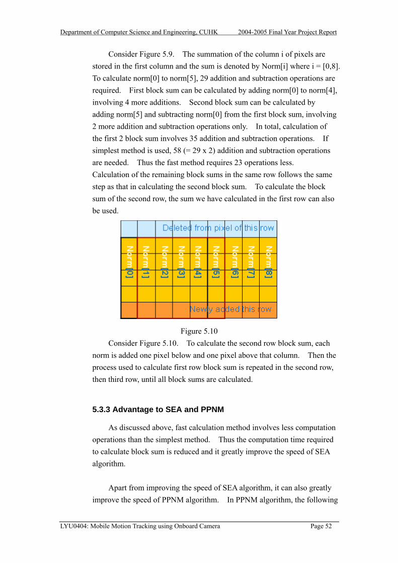
Formulation in terms of either instantaneous velocity or displacement is
possible. The instantaneous velocity v of a pixel and its displacement d are related by a constant ∆t which correspond to the temporal sampling interval. Consequently, in this case these two quantities are interchangeable. We adapt the formulation in term of displacement and thus when we talk about motion vector, we refer to displacement.
LYU0404: Mobile Motion Tracking using Onboard Camera Page 38

Department of Computer Science and Engineering, CUHK 2004-2005 Final Year Project Report
5.2 Block-Matching Motion tracking
These algorithms estimate the amount of motion on a block by block basis,
i.e. for each block in the previous frame, a block from the current frame is found, that is said to match this block based on a certain criterion.
Current Frame
Motion Vector
5.2.1
Tblock secondsecondof the directi
LYU0404: Mobile M
Previous Frame
Figure 5.1 Block matching
Principle of Block-Matching Motion Tracking
he image is divided into small rectangular blocks. For a selected in the image, it tries to find a similar block with same size in the image. It searches some neighborhood of some given points in the image. The assumption is that motion in the frame will cause most pixels within a block to move a consistent distance in a consistent on.
otion Tracking using Onboard Camera Page 39

Department of Computer Science and Engineering, CUHK 2004-2005 Final Year Project Report
Current Frame Previous Frame
(dx,dy)
The motion vector which
corresponds to the best match
Comparison of
blocks
Figure 5.2 Motion tracking: a block is compared against the blocks in the search
area in the current frame. The motion vector corresponding to the best match is returned.
The basic technique used for block-matching is a search. It is subject
to a tradeoff between accuracy and efficiency. The search space is defined by the search range parameter, generally referred to as W, as illustrated in Figure 5.3
One pixel
Figure 5.3 The search area in block-matching motion tracking techniques The red grid is the center pixel of the block
LYU0404: Mobile Motion Tracking using Onboard Camera Page 40

Department of Computer Science and Engineering, CUHK 2004-2005 Final Year Project Report
The value W represents the distance between center block, and the edge of the search space. W defines the numbers of evaluations of the cost functions that would occur in only one direction. In the rest of the report, we will refer to the number of calculations of the cost function as the number of weights.
Thus, the search space can be defined in terms of W as (2W+1) x
(2W+1). For example, the search ranges parameter of W = 6 would produce (12+1)2 = 169 weights. Each of these weights would be the result of the application of a cost function, and the best one is chosen. The location of the weight chosen as the best match is the motion vector.
The complexity of the motion tracking techniques can then be defined by the three main characteristics: (1) search algorithm, (2) cost function, and (3) search range parameter W.
For search algorithm, many fast algorithms have been developed that
they gain their efficiency by looking at only a fraction of the weights (will be discussed later).
For the cost function, there are a number of cost functions to evaluate
the "goodness" of a match and some of them are:
1. Mean Absolute Difference 2. Mean Squared Difference 3. Pel Difference Classification (PDC)
Some of these criteria are simple to evaluate, while others are more
involved. Different kinds of block-matching algorithms use different criteria for comparison of blocks. The block-matching algorithms obtain the motion vector by minimizing the cost functions.
5.2.2 Cost Functions
The cost function is a mapping from pixel block differences to the real numbers. In other words, cost functions are used to estimate the differences or similarities between any two given blocks. The smaller the values returned by the cost functions, the more similar the two pixel blocks
LYU0404: Mobile Motion Tracking using Onboard Camera Page 41

Department of Computer Science and Engineering, CUHK 2004-2005 Final Year Project Report
are to each other. Theses cost functions have the second largest effect on the complexity of motion tracking. The more intensive the function, the longer the search will take. Different cost functions have different accuracy and time complexity.
The Mean Absolute Difference (MAD)
|),(),(|1),(2/
2/
2/
2/dyjdxiGjiF
MNdydxMAD
n
ni
m
mj++−= ∑ ∑
−= −=
Where:
F(i,j) is the (MxN) block in the previous frame
G(I,j) is the reference (MxN) block in current frame and
(dx, dy) is the search location motion vector
The MAD is commonly used because of its simplicity.
The Mean Squared Difference (MSD)
22/
2/
2/
2/)],(),([1),( dyjdxiGjiF
MNdydxMSD
n
ni
m
mj++−= ∑ ∑
−= −=
The multiplications of MSD are much more computationally intense than MAD. However, the square on the difference term causes the function to be more complex and accurate than MAD.
The Pixel Difference Classification (PDC)
In order to reduce the computational complexity of MSD, MAD, and
CCF functions, Gharavi and Mills have proposed a simple block matching criterion, called Pixel Difference Classification [18]. The PDC functions is defines as:
∑∑=i j
jidydxTdydxPDC ),,,(),(
LYU0404: Mobile Motion Tracking using Onboard Camera Page 42

Department of Computer Science and Engineering, CUHK 2004-2005 Final Year Project Report
for (dx,dy) = {-W,W}.
Then, T(dx, dy, i, j) is the binary = 1 if tdyjdxiGjiF ≤++− ),(),( = 0 otherwise
where t is the predefined threshold value.
In this way, each pixel in a block is classified as either a matching pixel (T=1), or a mismatching pixel (T=0). The block that maximizes the PDC function is selected as the best matched block.
5.2.3 The Exhaustive Search Algorithm (SEA)
The most obvious searching algorithm for finding the best possible weights in the search area is the exhaustive search, or full search. All possible displacements in the search area are evaluated using the block-matching cost function. Therefore, no specialized algorithm is required. It is just a two-dimensional search.
W
Figure 5.4 The exhaustive search evaluates the cost function in all locations
in the search area
The advantage of the exhaustive search is that if we evaluate all the possible position in the search area, we can be guaranteed that we will find the absolute minimum.
The number of search locations to be evaluated by the exhaustive
search is directly proportional to the square of the search range W. The total number of search locations in the search area = (2W+1)2. Therefore
LYU0404: Mobile Motion Tracking using Onboard Camera Page 43

Department of Computer Science and Engineering, CUHK 2004-2005 Final Year Project Report
the exhaustive search algorithm has complexity of O(W2). As we can see, the size of W is very important to the speed of the exhaustive search algorithm.
Although, this algorithm in terms of accuracy and the simplicity of the
algorithm, it is very computationally intensive. Fast exhaustive search algorithms were developed that they achieve the same quality but with less computationally intensive. They are The Successive Elimination Algorithm (SEA) proposed by W.Li and E.Salari [11] and Progressive Partial Norm Matching (PPNM). Fast exhaustive search algorithm will be discussed in detail in Section 5.2.5
5.2.4 Fast Motion tracking Algorithms
The complexity of motion tracking is affected by the search algorithm and the complexity of the selected cost function. Apart from the exhaustive search algorithm which evaluates all the possible locations in a search area, there exists fast motion tracking algorithms. In the case of fast motion tracking, only a subset of all the possible locations is evaluated.
All fast searching algorithms are based on an assumption that the
matching error monotonically increases as the search position moves away from the optimal motion vector. That means the further we move away from the best position, the worst the match, and thus the higher the weight returned by the cost function. Hence, we would expect that a bowl would form around the minimum, as shown in figure 5.5 [19]
Figure 5.5 Weights generated by the cost function increase monotonically from the global minimum
If we assume that the inside of the bowl is a very smooth surface, we
will reach the minimum weight by following the direction of decreasing
LYU0404: Mobile Motion Tracking using Onboard Camera Page 44

Department of Computer Science and Engineering, CUHK 2004-2005 Final Year Project Report
weights. From everyday experience, we know that if we place a marble at the edge of a bowl, it will roll to the center. In the same way, if we look for a minimum weight adjacent to our starting position and then the minimum weight adjacent to that, we will in effect be directing our marble to the center of the bowl. In other words if we follow the direction of decreasing weights, we will eventually find the minimum weight. It is that assumption, that of a smooth bowl, which is the defining characteristic of the fast search algorithms. Regardless of their implementation, all of the fast search algorithms try to find the minimum position of the bowl by following the gradient downward.
Fast Search algorithms:
1. Three-Step Search algorithm 2. Diamond Search algorithm 3. Conjugate Direction Search
5.2.4.1 Three-Step Search Algorithm
The three-step search has been proposed by Koga et al [20] and implemented by Lee et al. [21]. An example of the three-step search algorithm is shown in figure 5.6.
Step 1
The Three-Step Search begins by calculating the weight at the center of
the search area. This is then set to the best match so far. A starting step size is defined as the search range divided by two: W/2. Using this step size, the 8 positions surrounding the center are searched: (0, W/2), (0,-W/2), (W/2, 0), (-W/2, 0), (W/2, W/2), (W/2,-W/2), (-W/2, W/2), and (-W/2,-W/2). The cost function of these eight locations is computed, and the resulting weights are compared to each other. The location with the lowest weight is chosen as best match and this location will become the center position of the next step. In the example of Figure 3.1, the current best location is (-4,-4).
LYU0404: Mobile Motion Tracking using Onboard Camera Page 45

Department of Computer Science and Engineering, CUHK 2004-2005 Final Year Project Report
Figure 5.6 An example of the three-step search algorithm.
Step 2
The step size is further divided by 2. The cost function is applied to the new eight surrounding locations around the current best match in the horizontal, vertical, and diagonal directions. Again, among these 9 points (the new eight and the current best match), the location which give the lowest value of cost function is chosen. In the example of Figure 3.1, the new best location from step 2 becomes (-6,4).
Step 3
The process of calculating the eight positions around the current best location continues until the step size = 1. In the example of Figure 3.1, the last step gives the best location (-7,5), which is the obtained motion vector.
5.2.4.2 Time Complexity
As the three-step search algorithm continuously divides the step size by two, and in each iteration, 8 points are calculated, the total complexity for the search is O(8logW). That is O(logW).
LYU0404: Mobile Motion Tracking using Onboard Camera Page 46

Department of Computer Science and Engineering, CUHK 2004-2005 Final Year Project Report
5.2.4.3 Problem of fast searching algorithms
Since all fast-search algorithms based on the assumption “The weight function in both the x and y directions increases monotonically as we move away from the minimum weight in the search area.”. However, this assumption is difficult to be valid. Consider the bowl example in figure 5.5, if the “bowl” is not smooth and it contains local minimum. Then the fast-search algorithm will not found a global minimal, instead it can only obtain a local minimal.
Apart from this, the choice of origin of the searching window will also affect the accuracy. If the origin is contained within the walls of the “bowl”, then by taking one step at a time, we should reach the center of the bowl, even if it is somewhat uneven. However, if the origin is located at the rim of the bowl, then the global minimum will not be found as illustrated in figure 5.6.
Correct Weight never found. Local Minimum found instead.
Figure 5.6 Bowl with extended rim illustrating the problem of selecting a
wrong origin
LYU0404: Mobile Motion Tracking using Onboard Camera Page 47

Department of Computer Science and Engineering, CUHK 2004-2005 Final Year Project Report
5.2.4.4 Conclusion
In our project, we want to motion tracking to be as accurate as possible, so we decided not to use the fast-search algorithms.
5.2.5 Fast Exhaustive Search Algorithm
Since we want the motion tracking to be very accurate, we decided to
use the exhaustive search. However, apart from accuracy, the speed is also our major concern, so there is a need to improve the speed of Exhaustive Search. W.Li and E.Salari have proposed a fast exhaustive search algorithm. That is the SEA algorithm.
5.2.5.1 The Successive Elimination Algorithm (SEA)
Before we talk about the principle of SEA, we need to define some
terms first. The sum of absolute difference (SAD) is the most widely used matching criteria; the SAD of two NxN blocks X and Y is defined as
∑∑= =
−=N
i
N
jjiYjiXyxSAD
1 1|),(),(|),(
The SEA proposed in [11] adopted the well-known Minkowski
inequality: (2) |)(||)(||)()(| 22112121 yxyxyyxx −+−≤+−+
To derive the following inequality:
= == = 1 11 1 i ji j
=≤−∑∑∑∑ ),(|),(),(| YXSADjiYjiXN NN N
|),(||||||||||| jiYXYX −≤−
Where:
X: reference block in previous frame Y: candidate block in current frame
||X|| = ∑∑ = =
N
i
N
jjiX
1 1),(
LYU0404: Mobile Motion Tracking using Onboard Camera Page 48

Department of Computer Science and Engineering, CUHK 2004-2005 Final Year Project Report
That means if the difference between the block sum (summing all pixels value inside a block) of candidate Z and the block sum of reference block X is greater than the minimum SAD(X,Y), block Z must not be the best match, since its SAD must be greater than the minimum SAD(X,Y) based on the inequality (3).
As the calculation of block sum requires only N2-1 additions and 1
subtraction for a NxN block while calculation of SAD requires N2-1 additions and N2 subtraction. Thus, calculating the block sum difference is much faster than calculating the SAD.
Then, by calculating the block sum difference first, we can eliminate
many candidates block before the calculation of SAD. Therefore, the speed of the block matching algorithm is increased.
5.2.5.2 PPNM (Progressive Partial Norm Matching)
After the SEA has been proposed, another algorithm is proposed to improve the speed of exhaustive search algorithm. That is the PPNM which is commonly used in video coding standard H.264.
The concept of PPNM is very similar to SEA. PPNM also makes use
of the Minkowski inequality to derive a matching criterion. The criterion further eliminates invalid candidate blocks before calculating the SAD of the blocks.
Based on the Minkowski inequality,
2121
22112121 )()()()(||||||||
AAAAfrom
YXYXYYXXYX
+≤+
−+−≤+−+=−
1xN Normorm1x4 N
M MxN Nor
M M
N N N Figure 5.7 Different size of sub-blocks
LYU0404: Mobile Motion Tracking using Onboard Camera Page 49

Department of Computer Science and Engineering, CUHK 2004-2005 Final Year Project Report
From the above inequality, we can derive the following inequality,
),(min
4141 YXSADYXYX xx =−>− ∑∑ In the example of Figure 5.7 , PPNM calculates the sum of difference of the 1xN norms between two block X and Z. If the sum is larger than the minimum SAD(X,Y), the SAD(X,Z) must be greater than the SAD(X,Y). PPNM further eliminates the invalid candidate blocks with the expense of higher computation load than SEA. In conclusion, by using the following inequality, many invalid candidate blocks are eliminated. Besides, there exists fast method for calculation of block sum (which will be discussed later).Thus further increases the speed of the exhaustive search.
44344214444 34444 2144 344 21SADPNSA
jiYXYXYXjiYX ),(),( 2211
SEA
−≤−+−≤−
5.3 Fast Calculation of Block Sum
5.3.1 Objective
In SEA algorithm, we need to calculate the block sum in the current frame in order to compute this matching criterion.
),(|),(),(|1 11 1
YXSADjiYjiXN
i
N
j
N
i
N
j
>−∑∑∑∑= == =
∑∑= =
N
i
N
jjiY
1 1),( term is the sum of pixel values in the previous block.
Since there is just one previous block, this block sum can be reused every time the matching criterion is computed.
∑∑= =
N
i
N
jjiX
1 1),( term is the sum of pixel values in a block in the current
frame. The simplest way to calculate this term is that for each block, we calculate the sum of pixel values inside that block. This method is
LYU0404: Mobile Motion Tracking using Onboard Camera Page 50

Department of Computer Science and Engineering, CUHK 2004-2005 Final Year Project Report
simplest yet inefficient. Since blocks inside the search window are overlapping to each other, sum of the overlapped pixels is redundant and wasting time. There is a better way to calculate the sum without adding the pixels redundantly.
5.3.2 Methodology
Figure 5.8
Consider Figure 5.8. There are two blocks, the first block has pixel 1-9, and the second block is the neighbor of the first block, it has pixel 4-12. The two blocks are overlapping with pixel 4-9 common to each other. First block sum is calculated by adding pixel 1-9. Second block sum can be calculated by adding pixel 4-12, but it is actually redundant to add pixel 4-9 as the sum of these pixels have already be calculated in the first block sum. This sum process involves 8 addition operations. A more efficient method is to make use of the first block sum. First block sum is the sum of pixel 1-9. If we subtract pixel 1-3 from the first block sum and add pixel 10-12 to it, we yield the second block involving only 6 addition and subtraction operations. Again, subtracting pixel 1-3 one by one is not efficient enough since sum of pixel 1-3 has also been calculated in first block sum. To further reduce the operation required, we can store the pixels in column with the expense of using larger memory storage. The increase in speed is best observed when the block size is large, so we use a larger block size as an example.
Figure 5.9
LYU0404: Mobile Motion Tracking using Onboard Camera Page 51
Department of Computer Science and Engineering, CUHK 2004-2005 Final Year Project Report
Consider Figure 5.9. The summation of the column i of pixels are stored in the first column and the sum is denoted by Norm[i] where i = [0,8]. To calculate norm[0] to norm[5], 29 addition and subtraction operations are required. First block sum can be calculated by adding norm[0] to norm[4], involving 4 more additions. Second block sum can be calculated by adding norm[5] and subtracting norm[0] from the first block sum, involving 2 more addition and subtraction operations only. In total, calculation of the first 2 block sum involves 35 addition and subtraction operations. If simplest method is used, 58 (= 29 x 2) addition and subtraction operations are needed. Thus the fast method requires 23 operations less. Calculation of the remaining block sums in the same row follows the same step as that in calculating the second block sum. To calculate the block sum of the second row, the sum we have calculated in the first row can also be used.
Figure 5.10
Consider Figure 5.10. To calculate the second row block sum, each norm is added one pixel below and one pixel above that column. Then the process used to calculate first row block sum is repeated in the second row, then third row, until all block sums are calculated.
5.3.3 Advantage to SEA and PPNM
As discussed above, fast calculation method involves less computation operations than the simplest method. Thus the computation time required to calculate block sum is reduced and it greatly improve the speed of SEA algorithm.
Apart from improving the speed of SEA algorithm, it can also greatly
improve the speed of PPNM algorithm. In PPNM algorithm, the following
LYU0404: Mobile Motion Tracking using Onboard Camera Page 52

Department of Computer Science and Engineering, CUHK 2004-2005 Final Year Project Report
matching criterion is needed to be computed.
),(|),(),(|11 1
YXSADjiYjiXN
j
N
i
N
j
>−∑∑ ∑== =
∑=
N
jjiY
1),( term, again, need to be calculated once and then reuse every
time the matching criterion is computed.
∑=
N
jjiX
1),( term is the sum of pixel values in one of the column in a
block. This sum is exactly the norm of the block we calculated during the fast calculation of block sum. Therefore, if we keep the norm value in
form of a 2D array, we can use that value as the term and thus
less computation is required to compute the sum of pixel values in that column again.
∑=
N
jjiX
1),(
5.3.4 Disadvantage
The only disadvantage of fast calculation of block sum method is that it increases the memory storage requirement. To facilitate the SEA algorithm, a (DY+DY+1) x (DX+DX+1) large block sum array is required. To facilitate the PPNM algorithm, another (DY+DY+1) x (DX+DX+BW+BW+1) large norm array is required. However, this increase in memory storage requirement is not significant when the search window size and the block size are both small.
LYU0404: Mobile Motion Tracking using Onboard Camera Page 53

Department of Computer Science and Engineering, CUHK 2004-2005 Final Year Project Report
5.4 Summary
The SEA and PPNM form a decision tree that eliminates about 50%-70% of invalid candidate blocks. The speed of the exhaustive full search is increased by nearly 3 times!
updateupdate
….
SAD SAD SAD
….
SAD….
Search range=2W+1
SEA
Tree pruning decision
PNSA
The smallest SAD
Total No of candidate Block: (2w+1)2
SEA < PNSA < SAD
SEA < PNSA < SAD
Probability of eliminating invalid candidate block:
Computation Load:
5.5 The Motion tracking Hypothesis
The previous chapter is dedicated to the current algorithms designed for motion tracking, while this chapter analyzes the underlying theory of motion tracking. We recall that motion tracking is the process used to discover the closest matching block, in the search area of the reference frame.
5.5.1 The Motion tracking Assumptions
If we attempt to describe the pitch of the motion tracking, we seem to generate three distinct concepts. Following definition of each of these ideas, we will expand on them to extract their implications.
LYU0404: Mobile Motion Tracking using Onboard Camera Page 54

Department of Computer Science and Engineering, CUHK 2004-2005 Final Year Project Report
5.5.2 Proximity Translation
The first of the concepts is a consideration of the physical properties of motion video sequences. Motion is communicated by translation of a group of pixels which resides in close physical proximity to one another. We refer to this definition as the Proximity Translation Hypothesis, and it forms the basis for block matching algorithms.
Figure 5.11 illustrating the proximity translation hypothesis. Motion is communicated by the translation of a group of pixels.
Very often, large solid objects exist in their entirety and their
components move in a predictable fashion. Namely, all parts of the bottle will be moving as the same rate since they are all attached, as illustrated in Figure 5.11.
5.5.3 Intensity Stability
In order for block matching to work, we assume the intensity of objects remain unchanged during translational motion. Of course, the same argument can be made for inanimate objects appearing in the video sequence. It is common that the intensity of objects changes only slightly for a small translational movement.
LYU0404: Mobile Motion Tracking using Onboard Camera Page 55

Department of Computer Science and Engineering, CUHK 2004-2005 Final Year Project Report
Figure 5.12 illustrating the intensity stability hypothesis.
Each region of pixels translates with little change in intensity or relative position.
5.5.4 Linear Motion Hypothesis
In most of the cases, we can assume that motion can be considered as relatively linear over short period of time. This means that an object will have a smooth continuous motion as it moves. It is quite believable that a driver would choose to drive continuously rather than applying the gas and brake in quick succession. This means that the car has a smooth continuous motion as it moves. The implication this produces is that if motion occurred at the rate of two pixels per frame between frames one and two, it is not unreasonable to assume that a motion of two pixels per frame may continue through frames two and three, three and four, etc. Though this may not last for extremely long in terms of seconds, linear motion may last over a period of several frames.
Base on the linear Motion hypothesis, we invent a new method
“Adaptive Search Window” which increases the speed of the block matching algorithm.
LYU0404: Mobile Motion Tracking using Onboard Camera Page 56

Department of Computer Science and Engineering, CUHK 2004-2005 Final Year Project Report
5.6 Optical Flow
Apart from block matching, there is another method for motion tracking -- Optical Flow.
In this chapter, we will discuss briefly how optical flow work and explain why we choose block-matching algorithm instead of optical flow for motion.
5.6.1 Overview of Optical Flow
Optical Flow is defined as the apparent motion of brightness pattern in an image. That is the velocity field of every pixel. This is illustrated by the Figure 5.13 below. The sphere is rotating from left to right, generating the optical flow field shown in the center.
Figure 5.13 Illustration of Optical Flow
Optical flow is very similar to motion field, but it is not equal to motion field. Ideally, it will be the same as the motion field, but this is not always the case.
5.6.2 Motion Fields
A velocity vector is associated to each image point, and a collection of such velocity vectors is a 2D motion field. It tells us how the position of the image of the corresponding scene point changes over time. It is the projection of 3-D velocity field onto image plane. In figure 5.11, a point po on a object moves with a velocity vo, then the image point pi can assigned a vector vi to indicate its movement on the image plane
LYU0404: Mobile Motion Tracking using Onboard Camera Page 57

Department of Computer Science and Engineering, CUHK 2004-2005 Final Year Project Report
Figure 5.14 Object motion creates a motion field on the 2D image plane
5.6.3 Difference between Optical Flow and Motion Field
The difference between Optical Flow and Motion Field can be illustrated as follow. Consider a perfectly uniform sphere. There will be some shadow on the surface. When the sphere rotates, such shading pattern won’t move at all. In this case, the apparent motion of the brightness pattern is zero, thus the optical flow is zero, but motion field is not zero.
Figure 5.15 Figure 5.16
In figure 5.15, the image intensity of the object changes due to the moving light source, so there is optical flow. However, the scene objects do not move, so there is no motion field. For figure 5.16, the scene object moves, so there is motion field. However, the image intensity does not change, so there is no optical flow.
LYU0404: Mobile Motion Tracking using Onboard Camera Page 58

Department of Computer Science and Engineering, CUHK 2004-2005 Final Year Project Report
5.6.4 Optical flow computation
There are three approaches to calculate the optical flow: the gradient-based approach, the correlation-based approach, or the spatiotemporal energy-approach. In this session, we will briefly explain the principle by using gradient-based approach.
One of the most important feature of optical flow is that it can be calculated simply, using local information. Let I (x, y, t) be the brightness of image, which changes in time to provide an image sequence. Firstly, there are some assumptions before deriving the formula of optical flow. The assumptions are 1. The change of brightness of a point to the motion of the brightness
pattern is constant (brightness constancy assumption) 2. Nearby points in the image plane move in a similar manner (velocity
smoothness constraint).
From the first assumption, we can obtain:
I(x,y,t) = I(x+u,y+v,t+dt) …….(1)
Where I(x,y,t) is the brightness of the image at location (x,y) and time t. (u,v) is the motion field at location (x,y) and time t+dt
From equation (1), it means the change of intensity w.r.t is zero, so we
can express it in another way:
0),,(=
dttyxdI
By chain rule, it can be shown that
LYU0404: Mobile Motion Tracking using Onboard Camera Page 59
Department of Computer Science and Engineering, CUHK 2004-2005 Final Year Project Report
)2.(..........0
0
0
0),,(
=++
=∂∂
+∂∂
+∂∂
=∂∂
+∂∂
+∂∂
=
ftfyvfxu
tIv
yIu
xI
tI
dtdy
yI
dtdx
xI
dttyxdI
where
fx = xI∂∂ ,fy =
yI∂∂ and ft =
tI∂∂
From equation (2), it indicates that the velocity (u,v) of a point must lie
on a line perpendicular to the vector (fx,fy) as illustrated as figure 5.17.
v
(fx,fy) fxu+fyv+ft=0
u
Figure 5.17 geometric explanation of equation (2)
Thus, the local constraints provide one linear equation in the variables u and v. As a result, the velocity (u,v) cannot be determined locally without applying additional constraints as illustrated by figure 5.18
LYU0404: Mobile Motion Tracking using Onboard Camera Page 60

Department of Computer Science and Engineering, CUHK 2004-2005 Final Year Project Report
Figure 5.18 aperture problem
As we can see from the above figure, we know that the green point should move to a point on the line, but we don’t know which one. This is known as aperture problem.
If we want to find a unique solution for equation (2), we need to have
another constraint, which is the second assumption -- The neighboring pixels in the image should have similar optical flow. Therefore, u and v need to have low variation with its neighboring pixels, so we set (u-uav) = 0 and (v-vav) = 0 where uav and vav are the average of neighboring pixels’ velocity.
In order to find a (u,v) that is as close as possible to the linear equation
(2) and also is locally smooth, we can use the Lagrange multipliers to minimize the flow error
E2(x,y) = (fxu + fyv + ft)2 + λ 2[(u- uav)2 + (v- vav)2]
Differentiating this equation w.r.t u and v provides equations for the
LYU0404: Mobile Motion Tracking using Onboard Camera Page 61

Department of Computer Science and Engineering, CUHK 2004-2005 Final Year Project Report
change in error, which must be zero for minimum.
Thus, by differentiating the flow error w.r.t u and v, this gives:
txavyxx ffuvffuf −=++ 222 )( λλ
tyavyyx ffvvfuff −=++ 222 )( λλ
Solving the two equations gives
DPfxuu av −= ……(5.34)
DPfyvv av −= …….(5.35)
where
ftfyvfxuP avav ++=
222 fyfxD ++= λ
We can solve equation 5.34 and 5.35 iteratively by using Gauss-Seidel
method. Algorithm 3.4: Optical Flow [Horn and Schunck 1980] k=0; Initialize all uk and vk to zero. Until decrease in flow error is negligible, do
DPfxuu k
avk −= −1 …………… (5.36)
DPfyvv k
avk −= −1 …………… (5.37)
The derivates of brightness fx,fy and ft can be obtained from a
sequence of frames
LYU0404: Mobile Motion Tracking using Onboard Camera Page 62

Department of Computer Science and Engineering, CUHK 2004-2005 Final Year Project Report
5.6.5 Comparison between optical flow and block-matching
In term of speed, optical flow is usually faster than block-matching,
because the motion vector is calculated by the formulas 4.44 and 4.45. It can be solved iteratively and usually, the number of iteration is smaller than the number of candidates block that need to be evaluated for block-matching.
In term of stability, block-matching is better than optical flow.
Stability here means that for block-matching, it is more resistant to lighting effect (including shadows, reflections, and highlights) while the optical flow is more susceptible to lighting effect. This is because optical flow is derived based on the assumption that the intensity of a pixel in the pattern is constant. Although block-matching is also based on the intensity stability assumption, the effects of lighting have less influence on block-matching algorithm. It is because block-matching algorithm considers a block of pixels, thus it is less susceptible to the lighting effects. Therefore, optical flow requires a stable environment to work fine.
In term of type of movement, optical flow can only measure small
movement while block-matching can also measure large movement, depending on the search range. It is because for the brightness constancy assumption I(x,y,t) = I(x+u,y+v,t+dt) to be true, dt usually is small. Therefore, for a large movement, usually this assumption will not hold. Comparing to optical flow, block-matching is less susceptible to lighting effect, so it can measure large movement.
LYU0404: Mobile Motion Tracking using Onboard Camera Page 63

Department of Computer Science and Engineering, CUHK 2004-2005 Final Year Project Report
Finally, we summarize the differences between the optical flow and block-matching by table 5.16
Optical Flow Block-Matching Speed Faster Slower Stability Less stable (affected by
lighting effect) More stable (less affected by lighting effect)
Movement measure
Small movement Small and Large movement
Floating point operations
Yes No
Table 5.16 Differences between optical flow and block-matching
5.6.6 Conclusion
We decide to use block matching instead of Optical Flow, because in the calculation of Optical Flow, it involves a lot of floating point operations. Recall from chapter 2 that Symbian phones don’t not have dedicated floating point unit.
Moreover, Optical Flow is affected more by the effects of lighting
while the block-matching is more resistant to these effects. As we want the motion tracking to be worked in different environment, we choose block-matching for our project instead of optical flow.
Adaptive Spiral SEA PPNM PDE SSD Algorithm
5.7 Partial Distortion Elimination
Unlike fast search algorithm, which only examine a few candidate blocks in order to determine whether it is the optimum block, full search algorithm ensure all candidate blocks in the current frame will be examined and the block with highest SAD inside the search window will be selected. However, there exist some fast full search algorithms which can search for the highest SAD block faster yet still ensure all blocks are examined. One of these algorithms is the partial distortion elimination (PDE) algorithm, which is excellent in removing
LYU0404: Mobile Motion Tracking using Onboard Camera Page 64

Department of Computer Science and Engineering, CUHK 2004-2005 Final Year Project Report
unnecessary computations efficiently. The PDE technique has been widely used to reduce the computational load in full search algorithm.
5.7.1 Methodology
PDE algorithm improves the speed of searching in shortening the calculation of Square of Absolute Difference (SAD) between each currently matching block with the previous block. Its main objective is to use the partial sum of matching distortion to eliminate impossible candidates before complete calculation of SAD in a matching block. That is, if an intermediate sum of the matching distortion is larger than the minimum value of the SAD at that time, the remaining computation for the SAD is abandoned. The SAD of the matching block is calculated by:
∑∑= =
≤++−=N
i
N
j
WyxwhereyjxiYjiXyxSAD1 1
|,||),(),(|),(
The kth partial sum of matching distortion is calculated by:
∑∑= =
≤=++−=k
i
N
j
WyxandNkwhereyjxiYjiXyxPSAD1 1
|,|,...,3,2,1|),(),(|),(
W represents the size of search window and N the matching block size.
Usually, the SAD of a block is obtained by adding the pixels inside the block in row by row basic. We can check if the partial sum of matching distortion exceeds the current minimum SAD after each row is added to the PSAD. Remaining calculation will be quit if PSAD(x, y) > SAD(x, y) and this impossible candidate block is eliminated from consideration.
Checking PSAD(x, y) > SAD(x, y) can be done every time after a pixel
is added to the PSAD(x, y) or after a row of pixels is added. The latter scheme is preferred because the code overhead of checking PSAD(x, y) > SAD(x, y) is too large. If the block width and block height is N, the former scheme costs at most N2 – N comparison operations more than the latter scheme while the former scheme can at most stop the remaining calculation 3N addition operations earlier than the latter scheme. For large N, N2 – N is much larger than 3N. Since the cost outweighs the advantage, the latter scheme is used instead.
LYU0404: Mobile Motion Tracking using Onboard Camera Page 65

Department of Computer Science and Engineering, CUHK 2004-2005 Final Year Project Report
5.7.2 Result
From the experimental result we have done on OpenCV program, PDE algorithm is faster than exhaustive search algorithm (ESA) by 3 times on average. PDE algorithm does not increase the memory storage requirement, does not involve complex operation and does not increase code overhead much, yet it can effectively remove the impossible candidate blocks during calculation of SAD. Any algorithm that requires the calculation of SAD can incorporate with PDE to improve its speed in matching optimum block. And because this algorithm just affects the calculation of SAD, it is compatible with other type of algorithms, such as SEA and PPNM.
5.7.3 Possible Improvement
The speed of PDE algorithm depends on how fast computation of SAD is stopped according to the partial sum of SAD. Kim, Byun and Ahn [1] proposed some methods which can further reduce computations with the same accuracy as that of conventional full search method. They mathematically derived the relationship between spatial complexity of the previous block and the matching distortion. In the derivation, they showed that the matching distortion between the current blocks and previous block is proportional to the image complexity of the previous block. That is, larger SAD can be obtained by first calculating the matching distortions of the image area with large gradient magnitudes, that is, more complex area. Through this, unnecessary computations can further be removed. They proposed to use adaptive sequential matching start with the left, right, top or bottom and row vector based matching in which matching order is determined by the image complexity. The PDE algorithm with adaptive sequential matching and row vector based scan can be expressed as follows:
Figure from reference paper [1] LYU0404: Mobile Motion Tracking using Onboard Camera Page 66

Department of Computer Science and Engineering, CUHK 2004-2005 Final Year Project Report
Experimental result from reference paper [1]
The above table is the experimental result done by Kim, Byun and Ahn.
The sequential, dither and complexity algorithms are the modified PDE algorithms. Original PDE algorithm has about 30% computation reduction over the original FS algorithm. The sequential and dither PDE algorithms have a bit better reduction than the original PDE algorithm while the complexity PDE algorithm shows greater improvement in reduction. However, the code overhead of using complexity is high and the implementation is complex, the actual improvement of speed may be not so high. We haven’t incorporated this kind of adaptive matching scan method into our algorithm because of its complexity in implementing, but later we may try improving PDE algorithm using this method.
5.8 Adaptive Search Window
In the implementation of video compensation and coding, each block in previous frame has fixed position and the object tracked by each one varies from frame to frame. At frame 1, a block is tracking object A; however, at frame 2, that block may be tracking object B which motion is totally different from object
LYU0404: Mobile Motion Tracking using Onboard Camera Page 67

Department of Computer Science and Engineering, CUHK 2004-2005 Final Year Project Report
A. Since each block does not track the same object, it is useless for it to carry history for the motions of its tracking objects.
In our application, on the contrary, it is very useful to carry history of the
motions. In contrast with tracking objects in a frame, our goal is to track the motion of the camera. If we reasonably assumed the things captured by the camera do not move, when the camera moves, all these things move together with about the same displacement. Therefore, the whole frame can be regarded as one object. With this assumption, block at any position in the previous frame actually tracks the motion of the same object. Thus, history of motions is always useful to any candidate block.
Conventionally, search window is defined as a rectangle with the same
center as block in previous frame, extended by W pixels in both directions. This definition is reasonable but it can be improved based on the history of motions. With the history, search window can be newly defined as a rectangle with its center being predicted from the previous motion vector and the previous block position.
5.8.1 Methodology
DLPLPvvv
+−= ')1( … (5.38)
P: Predicted Displacement of object
P’: Previous Predicted Displacement of object
L: Learning Factor, range is [0.5, 1.0]
D: Previous Displacement of object
The next displacement of object is predicted using exponential averaging over previous displacement and previous predicted displacement of the object. The previous predicted displacement is involved to predict a new displacement in order to reduce the effect of detection error which may exist in the previous displacement returned from the algorithm. That is, if the object is detected to be moving to the left for a while, a sudden detection telling that it is moving up will not cause the search window to shift upward too much because it is usually due to detection error. But if there is a second detection telling that it is still moving up, the search window will
LYU0404: Mobile Motion Tracking using Onboard Camera Page 68

Department of Computer Science and Engineering, CUHK 2004-2005 Final Year Project Report
shift upward much more. It is because the past previous displacement and previous displacement affect the predicted displacement seriously. Therefore, if the frames captured by a camera are noisy, the learning factor should be set to a low value, say 0.5, so that a detection error will not affect the search window much. If the frames are not so noisy, the learning factor can be set higher, say even 1.0, so that predicted displacement solely depends on the previous displacement.
5.8.2 Comparison with conventional method
Figure 5.19
To evaluate the performance of the adaptive search window method, we used web camera to track the motion of an object and plot a graph (Figure 5.19) showing its x-axis velocity against time. The data points are collected when we run the Adaptive Spiral SEA PPNM PDE SAD Algorithm. The velocity means how many pixels the object has moved, positive value means it is moving to the right direction, negative value means to the left. The algorithm is run every second, thus the velocity just equals the magnitude of the x-component of the motion vector. The object is moving to the left and right periodically, thus the curve move up and
LYU0404: Mobile Motion Tracking using Onboard Camera Page 69

Department of Computer Science and Engineering, CUHK 2004-2005 Final Year Project Report
down. The search window size is 41 x 41 and the magnitude of the motion is 40 pixels/s, so all the true optimum points fall within the conventional search window. In this case, although the conventional search window method is possible to find the true optimum point on every run, the speed of the algorithm will not be high, it is because the average magnitude of the object’s velocity is high, which means the distance between the optimum point and the initial search center is long and therefore minimum SAD is found only after many computations.
Considering the Figure 5.19, if the search window size is set to 20 x 20,
conventional search window method will definitely can’t find some true optimum points on some runs of algorithm since the true optimum point falls out of the search window at some points, say at time=80s. For the same search window size, the adaptive search window method does not have this error.
Figure 5.20
The displacement of the object is predicted using the equation (5.38) with L=0.5 during the motion tracking, the graph of predicted velocity (=displacement) over time is plotted on the Figure 5.19 to give Figure 5.20.
LYU0404: Mobile Motion Tracking using Onboard Camera Page 70

Department of Computer Science and Engineering, CUHK 2004-2005 Final Year Project Report
The two curves look similar and difficult to analyze, thus another graph showing the difference between the two curves is plotted.
Figure 5.21
Figure 5.21 is a graph showing the relative velocity between predicted velocity and actual velocity over time. The maximum magnitude of the curve is below 20 pixels per second. The true optimum point always falls into the search window and thus no serious detection error would result even if the search window size is 20 x 20. Moreover, the average magnitude of the object’s velocity is relatively lower, which means the distance between the optimum point and the initial search center is shorter and thus less computation is required. Figure 5.22 is a graph showing the relative velocity over time using different learning factor. Since noise in the image captured by web camera is not too high, large learning factor generally gives better prediction of motion. From the graph, point curve with learning factor = 1.0 is always the closest one when compared with other curve with learning factor = 0.5 and 0.8. Thus, on PC, learning factor = 1.0 can be used, while on mobile, since the noise in the image captured by the camera on mobile phone is relatively higher, a bit lower learning factor can be used.
LYU0404: Mobile Motion Tracking using Onboard Camera Page 71

Department of Computer Science and Engineering, CUHK 2004-2005 Final Year Project Report
Figure 5.22
5.8.3 Constraint of each method
Accuracies of both methods are motion dependent. Based on the size of the search window, we can represent a constraint on the velocity of object by an equation. Unsatisfying this constraint leads to detection error. For the conventional search window method, the constraint for the object’s velocity can be represented by:
| Velocity | < W pixels/s … (5.39)
Where W is half of the search window width/height provided that the algorithm run
every second.
For the adaptive search window method, the constraint becomes:
|Relative Velocity | < W pixels/s or | Acceleration | < W pixels/s2 … (5.40)
LYU0404: Mobile Motion Tracking using Onboard Camera Page 72

Department of Computer Science and Engineering, CUHK 2004-2005 Final Year Project Report
5.8.4 Analysis
1. When velocity of object is low, both the conventional and adaptive methods will not have detection error.
2. When velocity is high, conventional method can’t ensure the result is the true optimum point while adaptive method can ensure provided that the object is not accelerating fast at the same time.
3. When acceleration is high, conventional method will not have detection error if the velocity can be kept lower than W pixels/s while adaptive method will have detection error. But conventional method will also have detection error if acceleration is higher than 2W pixels/s2 since final velocity would definitely be higher than W pixels/s. Thus, conventional method can’t ensure the result is the true optimum point when acceleration is high, either.
The most important issue is how these constraints affect users’
movements. Considering a user is holding a camera-equipped mobile phone and moving it. If conventional method is used, we concern constraint (5.39), which means user must move slow enough in order to ensure accurate motion detection. This is not desirable to user and very inconvenient to use. If adaptive method is used, user can move as fast as he wants but the acceleration must not be high, which is relatively easier to achieve and more desirable. If user does not shake the phone rapidly, natural motion of hand normally does not have too high acceleration. In order word, adaptive method allows user to move in a more natural way.
5.8.5 Conclusion
If user moves naturally with small acceleration, adaptive search method has two advantages over the conventional one. Firstly, it increases the chance of finding the true optimum point. Secondly, it reduces the computation steps, especially if spiral scan method is used together. Since in spiral scan method, previous block will first match the center region of the adaptive search window, which is highly probably to contain the true optimum point. As distance between the starting search point and the true optimum point becomes shorter, the previous block can match the block at optimum point earlier and thus the computation steps is reduced. The detail of spiral scan method is discussed in the next section.
LYU0404: Mobile Motion Tracking using Onboard Camera Page 73

Department of Computer Science and Engineering, CUHK 2004-2005 Final Year Project Report
5.9 Spiral Scan Method
5.9.1 Raster Scan method
Commonly used block scanning method in the field of video compensation and coding is the “Raster Scan” method. That is, when we use the previous block to find a best match in the current frame, we calculate the Sum of Absolute Difference (SAD) of the previous block with the current block C00 at the left top position first, and then calculate that with the current block C01 with center one pixel next to C00 in the same row. This process repeats until all SAD of the current block in the first row is calculated. Then the process repeat in the next row until all SAD of current block in the search window is calculated. In short, it scans from top to bottom, from left to right. The advantage of this method is that it is very simple to implement and code overhead is very small.
5.9.2 Analysis
The order of scanning can affect the time to reach the optimum candidate block. When SEA, PPNM and PDE method are used, this property can affect the amount of computation. The reduction of calculation in obtaining the motion vector with these algorithms depends on how fast the global minimum of SAD is detected. If we find the global minimum in the calculation of the matching error faster, complete computation of the matching error in a block is avoided more. In PDE method, calculation of the SAD stop if the sub-blocks SAD between the two block is already larger than minimum SAD. If optimum candidate block is reached earlier, global minimum SAD will be found earlier. For each current block, a smaller sub-block SAD is already larger than the minimum SAD, thus calculation of SAD stop earlier and amount of computation is reduced. In SEA method, impossible candidate block is eliminated before its PPNM and SAD are computed based on the following criterion:
),(|),(),(|1 11 1
YXSADjiYjiXN
i
N
j
N
i
N
j
>−∑∑∑∑= == =
LYU0404: Mobile Motion Tracking using Onboard Camera Page 74

Department of Computer Science and Engineering, CUHK 2004-2005 Final Year Project Report
Thus global minimum SAD found earlier leads to less computation on PPNM and SAD. In PPNM method, impossible candidate block is eliminated before its SAD are computed based on the following criterion:
),(|),(),(|11 1
YXSADjiYjiXN
j
N
i
N
j
>−∑∑ ∑== =
In order reach the optimum candidate block earlier, candidate blocks with higher probability to be an optimum block should be reached first. If all candidate blocks have equal probability to be an optimum block, order of scanning doesn’t matter. But if candidate block at the center region of the search window has a higher probability to be an optimum block, scanning the center region first highly improves the speed of our algorithm. This is our motivation to use spiral scan method as the block scanning method.
5.9.3 Spiral Scan Method
Instead of starting at the left top position, we can start finding the SAD at the center of the search window first, then finding the SAD at position that are 1 pixels away from the center, then 2 pixels away from the center, …etc. When adaptive search window method is used, most of the motion vectors are center biased. That is, the optimum point would have higher probability to locate at the center of the search window. Since spiral scan method scans the center position of the search window first, it has higher chance to reach the optimum block earlier. As discussed above, reaching the optimum block earlier improves speed of our algorithm.
5.9.4 Result
Spiral scan method requires larger memory storage than Raster Scan method if fast calculation of block sum is used together. In Raster Scan method, only a row of block sum is needed to be stored. Since SAD of current blocks is calculated row by row, the row of block sum can be updated to store the block sum of the second row after the first row is finished. However, in spiral method, since SAD of current blocks is calculated in spiral order, not row by row, the whole block sum 2D array is needed to be stored. Although larger memory storage is required, speed of algorithm not only do not degraded, but improved a lot due to earlier reaching of optimum block.
LYU0404: Mobile Motion Tracking using Onboard Camera Page 75

Department of Computer Science and Engineering, CUHK 2004-2005 Final Year Project Report
5.10 Motion Tracking Algorithm Development
Motion Tracking
Optical Flow Blocking Matching
1. Lower Computation Complexity
2. Suitable to implement in mobile
devices where floating point, division
and multiplication operation is slow
Exhaustive Search Algorithm (ESA)
Fast Algorithm (FA)
1. Give suboptimal Result
poor accuracy
Three Step Search
(TSS)
2D Logarithmic
Search
Diamond Search
1. Good accuracy, Find
best match
2. Slow, but can be
improved
Successive Elimination Algorithm
(SEA)
Partial Distortion Elimination (PDE)
1. Faster
2. No performance
loss, i.e. same
performance as ESASEA + Progressive Norm Successive Algorithm (PPNS)
1. Further improvement
over SEA
LYU0404: Mobile Motion Tracking using Onboard Camera Page 76

Department of Computer Science and Engineering, CUHK 2004-2005 Final Year Project Report
1. Further improvement over SEA +
PPNM algorithm by better scanning
method
2. Assumption: motion is center-biased,
i.e. most of the movement around
center
SEA + PPNM + PDE + Spiral Scan Search
Spiral Scan + SEA + PPNM + PDE + Adaptive Search
Window
SEA + PPNS + Partial Distortion Elimination
(PDE)
1. A paper (Year 1999) suggested that
PDE can be integrated with SEA
algorithm
2. We have tested that the PDE really
improve the speed of SEA+PPNM
algorithm
Our Final Algorithm
1. We proposed adaptive search window
method that makes use of the previous
motion tracking history to make good
guess on the next optimum position
and increase algorithm speed by
searching that area first
2. This make the assumption made by
Spiral Scan method no longer an
assumption, but a highly probably
event
Hierarchical Adaptive Spiral Scan + SEA +
PPNM + PDE 1. Possible improvement over our final
Algorithm
LYU0404: Mobile Motion Tracking using Onboard Camera Page 77

Department of Computer Science and Engineering, CUHK 2004-2005 Final Year Project Report
Chapter 6: Feature Selection
We use the block matching algorithm for the motion tracking, so which block in the previous frame should be chosen for block matching? We must make a compromise between two contradictory desires. On one hand we would like features to be as descriptive as possible: The block chosen should facilitate the block matching algorithm and increase the accuracy of the algorithm. On the other hand, we also want feature extraction to be robust across thousands of video frames. In our application, our purpose is to provide real-time tracking on the mobile device. Thus we implement our own feature selection algorithm instead of using well-known feature selection algorithms which usually have a high computation load. Our algorithm, although is simple, it bears certain level of robustness.
6.1 Implementation
Intuitively, if we want to select a good feature block for block matching, it should not select a block in the flag region. As in figure 6.1, although the window has moved to the right, we will not able to detect the movement. It is because all neighbors of the feature block have the same color, so they will have same SAD with the feature block. We can conclude that because motion is indeterminate when spatial gradient is near zero. Therefore, we cannot find a best match as all of the candidate blocks have the same SAD (Remember that we will choose the candidate block with the minimum SAD as the best match). Thus, the accuracy is decreased greatly.
Feature Block
Original position New position
Figure 6.1 A reference block in flag region
LYU0404: Mobile Motion Tracking using Onboard Camera Page 78

Department of Computer Science and Engineering, CUHK 2004-2005 Final Year Project Report
In order to prevent the selection of a flat-region block, the block selected should be complex. We can evaluate the complexity of a block by calculating the local variance within the block Sxy. If the block is totally flat, the local variance will be 0 while the local variance will be large if the block is complex. The selection of a highly complex block will increase the chance of Partial Distortion Error (PDE) since the difference between candidate blocks and the reference block will be large even for a small movement. Thus increase the speed of the algorithm.
Apart from the complexity of a block, the feature block should have large
intensity difference between neighbor blocks. Consider the figure 3.x, although either one of the block is complex, the complex block repeat itself all over the window. Hence, it affects the accuracy of block matching.
Figure 6.2 repeated pattern background
In order to solve the above problem, we can use Laplacian mask to calculate the intensity difference between the current block with its neighbors. Originally, Laplacian operator is used as edge detector that it find out how brighter the current pixel is than the neighborhood.
- Gray level discontinuity large output - Flat background zero output
Firstly, we divide current frame into small rectangular blocks. For each block, sum all the pixels value, denoted as Ixy, and store it in 2D array (Intensity of the block). After that, we calculate the variance of each block which represents the complexity of the block. Apply Laplacian Mask for the 2D array (Masking). Since the Laplacian operator indicates how difference the reference block is than the neighbors, we select the block which has the largest Ixy and
LYU0404: Mobile Motion Tracking using Onboard Camera Page 79

Department of Computer Science and Engineering, CUHK 2004-2005 Final Year Project Report
large variance as feature block
6.2 Laplacian Operator
The Laplacian L(x,y) of an image with pixel intensity values I(x,y) is given by:
22
2
22
22
yf
xIf
∂∂
+∂∂
=∂
Where
),(2),1(),1(2
2
yxfyxfyxfx
I−−++=
∂∂
),(2)1,()1,(2
2
yxfyxfyxfy
I−−++=
∂∂
Negative Definition ),(4)1,()1,(),1(),1(2 yxfyxfyxfyxfyxff −−+++−++=∂
Positive Definition ),(4)]1,()1,(),1(),1([2 yxfyxfyxfyxfyxff +−+++−++−=∂
Diagonal derivatives can also be included.
In our application, we use the positive definition with diagonal derivates. Then the Laplacian operator can be represented by the Laplacian mask (Figure 6.3)
Figure 6.3 Laplacian Mask
Then we apply the Laplacian mask to the image. For example, in figure
LYU0404: Mobile Motion Tracking using Onboard Camera Page 80

Department of Computer Science and Engineering, CUHK 2004-2005 Final Year Project Report
6.4, the mask values are multiplied by corresponding pixels values, and then summed up. The final value is returned to the output image at the position corresponding to the centre element of the window. The mask is then moved by one pixel (not the window size) to its next position and the operation is repeated.
Output Image
Input Image
Laplacian Mask
Figure 6.4
Output Value is -86, because: (-1x68)+ (-1x62) + (-1x66) + (-1x120) + (8x80) + (-1x37) + (-1x62) + (-1x65) + (-1x61) = 99
6.3 Experimental Result
We have tested our feature selection algorithm in different cases:
1. A black rectangle in a white background 2. A black rectangle in a repeated pattern background
In case 1, we want to test the performance of our feature selection algorithm
on a flat region. In a white region background, we draw a black rectangle on it. Intuitively, the black rectangle should be selected as the reference block for block-matching. Our feature selection algorithm selects the corner of the black rectangle as the reference block as shown in figure 6.5. It is a good tracking location because of the brightness difference between the black and white colors.
LYU0404: Mobile Motion Tracking using Onboard Camera Page 81

Department of Computer Science and Engineering, CUHK 2004-2005 Final Year Project Report
As we can see, the block selected contains black pixel values. Hence our algorithm can prevent the selection of flat-region block as reference block.
Figure 6.5 Experiment on feature selection
In case 2, we apply the feature selection to a background of repeated pattern with a black rectangle as illustrated in figure 6.6. If we do use feature selection algorithm Again, it selects the black rectangle block as the reference block. Thus, we can see that our algorithm will never select a block that will lead to indeterminate movement. If we select a block as in figure 4.x rather than the black rectangle, when the object move to the right, the block-matching algorithm finds the best-match wrongly as illustrated in figure 6.7
LYU0404: Mobile Motion Tracking using Onboard Camera Page 82

Department of Computer Science and Engineering, CUHK 2004-2005 Final Year Project Report
Figure 6.6
LYU0404: Mobile Motion Tracking using Onboard Camera Page 83

Department of Computer Science and Engineering, CUHK 2004-2005 Final Year Project Report
Figure 6.7 Hence, we can see that if we can select a good feature block as the reference block, the performance of block-matching is guaranteed that it will not be acceptable.
6.4 Conclusion
For block matching, if we select either a block in flat region or in a repeated
pattern region as the reference block, the accuracy will be affected significantly. Block mismatch always happens. After using the feature selection algorithm, it will ensure that a block selected will not be in flat region or repeated pattern region. Hence the error is reduced. Since our feature selection algorithm requires a small computation load, the speed of the block matching algorithm is not affected.
LYU0404: Mobile Motion Tracking using Onboard Camera Page 84

Department of Computer Science and Engineering, CUHK 2004-2005 Final Year Project Report
Chapter 7: Applications
In this chapter, we will discuss what kinds of applications can be developed from motion tracking and benefits of using it. Motion tracking has been widely used in many areas, for example video compression, robotics, video surveillance, etc. It is possible to develop different kinds of applications. Moreover, it can be used as an innovative input method to many applications, for example, games, camera mouse and gesture input. We will focus on how motion tracking can be used as an input method for different applications.
7.1 Development procedure
Before we talk about what applications can be made, we talk about how a motion-tracking application can be developed. The flow chart of developing motion-tracking application is shown below:
Video Source captured by camera
Already selected feature block?
P Source Frames
Figure 7.1 Flow Chart of developing motion tracking application
Feature Selection
delay Block-matching Algorithm using two image frames
No
T
Server A
Frame tYes
MV of reference block
Frame t-1
A feature block is selected as reference block
LYU0404: Mobile Motion Tracking using Onboard Camera Page 85

Department of Computer Science and Engineering, CUHK 2004-2005 Final Year Project Report
Input Stage In order to use the motion tracking technique, we need to extract frames from
video. This process is procedure “P” shown in the Figure 5.1. There are several ways to do that. In PC, we use libraries from OpenCV and in Symbian, we use the view finder to extract the frames from video. OpenCV provides a lot of library for us to manipulate the video. Firstly, we need to reserve the camera to use. After that, by calling cvQueryFrame( ), a frame will be extracted and stored in a 2D array. Then we can get the frame data by using a pointer. Processing Stage After we have extracted frames from video, we use two consecutive frames Ft-1 and Ft for block-matching. If we have not selected a reference block for tracking, feature selection algorithm will be applied to find a good feature block as reference block. After that, we can use the block-matching algorithm to find the motion vector of the reference block. Output Stage Once a motion vector is found, it will be output to a server by using transmission medium “T”. We can use different kinds of transmission medium, eg Serial Cable, USB, Bluetooth, etc. The server is responsible for receiving the motion vector and interpreting it. Finally, the server will give corresponding commands to the application “A”. Conclusion Different kinds of application can be developed by following the flow chart above. Moreover, the motion tracking technique can be used in different platforms, eg PC, PDA, Symbian phone, provided that they support video capture and libraries for image manipulation.
7.2 Example Applications
In order to illustrate the idea of innovative input method using the motion tracking, we have implemented two applications one in the PC and one in the Symbian phone based on the block-matching algorithm that we have discussed before.
LYU0404: Mobile Motion Tracking using Onboard Camera Page 86

Department of Computer Science and Engineering, CUHK 2004-2005 Final Year Project Report
7.2.1 Pong Game
Here show the screenshot of the pong game. The left one is developed on the PC written by C# while the right one is developed on the Symbian and tested by the emulator.
Figure 7.2 Screenshot of the pong game
Traditionally, users play the game by using the keyboard to control the movement of the paddle. It would be much more interesting if users’ movements are involved in playing the game. We implemented the block-matching algorithm in the game so that the paddle could be controlled by the users’ movement. When the user moves the camera or camera phone, the padding will move according to the direction of movement. Because of the motion tracking technique, the traditional pong game has become much more interesting.
The pong game is just one of the applications to illustrate the benefits
of using motion tracking technique. There are a lot of applications in which this technique can be used
LYU0404: Mobile Motion Tracking using Onboard Camera Page 87

Department of Computer Science and Engineering, CUHK 2004-2005 Final Year Project Report
7.2.2 Virtual Mouse
We are implementing a virtual mouse system that users can use their Symbian phone as a mouse for the desktop computers. We further developed our “MotionTrack” application. By following the flow chart in figure 5.x, we developed a server as shown in figure 6.x and the server will receive the motion vector via Bluetooth. It will instruct the cursor to move according to the motion vector.
Figure 7.3 A server program for receiving motion vector
7.3 Other Possible Application
7.3.1 Camera Mouse
In the society, there are people with serve disabilities that they can only move their heads. Because of their disabilities, they cannot use the computers for any purpose. Therefore, there is a need to develop a tool for the physically handicaps so that it can provide a chance for them to access the computers. Due to their limitation of movements, a motion tracking system, Camera Mouse, can helps them to access the computer. Therefore, they can acquire knowledge more actively, use the Internet, and access computer-controlled techniques such as automated wheel-chairs.
The idea of camera mouse system is that the system tracks the
computer user’s movements with a video camera and translates into the movements of the mouse pointer on the screen. It is particularly useful for physically handicaps. For example, people with serve disabilities can control the movements of the mouse pointer by moving their heads.
LYU0404: Mobile Motion Tracking using Onboard Camera Page 88

Department of Computer Science and Engineering, CUHK 2004-2005 Final Year Project Report
Chapter 8: Experimental Result
8.1 Computation load of SSD and SAD
There are two matching criteria commonly used in block matching algorithm, they are SAD and SSD. We have tested how much SAD is faster than SSD by a simple code. Recall that the equations of SAD and SSD are as follow:
∑∑= =
≤++−=N
i
N
j
WyxwhereyjxiYjiXyxSAD1 1
|,||),(),(|),(
∑∑= =
≤++−=N
i
N
j
WyxwhereyjxiYjiXyxSSD1 1
2 |,|]),(),([),(
The code to test the performance of SSD is as follow:
for(int i=0; i<100; i++) for(int j=1; j<=1000000; j++){ d = dataA[i] - dataB[i]; sum += d*d; }
Code snippet 1 This code snippet carries out 100 million operation of SSD. The sum of
squared difference is stored in “sum”. This code snippet costs 922ms to run in a 2.0GHz personal computer.
Similarly, the code to test the performance of SAD is as follow:
for(int i=0; i<100; i++) for(int j=1; j<=1000000; j++){ sum+=abs(dataA[i] - dataB[i]); }
Code snippet 2 This code snippet carries out 100 million operation of SAD. The sum of
absolute difference is stored in “sum”. This code snippet costs 1297ms to run. Surprisingly, absolute operation is much slower than multiplication operation. This is because in this code snippet, abs() function is called instead of doing simple arithmetic operation. Calling function involves procedure prolog which
LYU0404: Mobile Motion Tracking using Onboard Camera Page 89

Department of Computer Science and Engineering, CUHK 2004-2005 Final Year Project Report
produce a significantly large overhead when the function is called very frequently. In order to improve the speed of absolute operation, we handle the absolute operation by ourselves rather than use the Math class function, the code snippet become:
for(int i=0; i<100; i++) for(int j=1; j<=1000000; j++){ sum+=dataA[k]>dataB[k]?dataA[k]-dataB[k]:dataB[k]-dataA[k]; }
Code snippet 3 This code snippet costs 781ms to run which is about 15% faster than
snippet 1. This code snippet is more efficient because it doesn’t involve function calling. In total, snippet 4 requires 1 comparison and jump operation ( dataA[k]>dataB[k]? ), 1 difference operation ( dataA[k] – dataB[k] OR dataB[k] – dataA[k] ), 1 summation operation and 2 for loop. This code snippet is not yet optimal, it is because dataA[] and dataB[] are image pixels arrays, accessing elements in these arrays cost a long time. To minimize the access of the image array and computation operations, we change the snippet to:
for(int i=0; i<100; i++) for(int j=1; j<=1000000; j++){ d = dataA[k] - dataB[k]; if(d>=0) e+=d; else e-=d; }
Code snippet 4 This code snippet costs only 672ms to run which is about 30% faster than
snippet 1. This code snippet is more efficient than snippet 3 because it requires the same amount of computation operations while reduced the number of access of image arrays to two.
We concluded that computation load of SAD is smaller than that of SSD. With code snippet 4, SAD is about 30% faster. Therefore, we would use code snippet 4 in the calculation of SAD matching criterion.
LYU0404: Mobile Motion Tracking using Onboard Camera Page 90

Department of Computer Science and Engineering, CUHK 2004-2005 Final Year Project Report
8.2 Improvement of ESA by SEA/PPNM
Testing Environment:
CPU – 2.0GHz Pentium 4
Block Matching Parameter:
Block Width 31 pixels Block Height 31 pixels Search Window Width 81 pixels Search Window Height 81 pixels
Measuring Method:
In SEA and PPNM, SAD of the eliminated impossible candidate blocks
needs not to be calculated. Thus we measure the performance of SEA and PPNM by counting the number of blocks involved in calculating the SAD.
Algorithm # of blocks
calculated in SAD Speedup Computation Time
(x 5) Speedup
ESA 6561 1.00 2140 ms 1.00 SEA+PPNM 2304 2.85 516 ms 4.15
SEA+PPNM algorithm show significant improvement in speed over ESA.
It is about 4 times faster than ESA.
8.3 Enhancement of SEA/PPNM by PDE
Experiment of this part is carried out in the same testing environment using block matching parameter as before.
Measuring Method:
Since in PDE, condition “PSAD(x, y) > SAD(x, y)” is checked every time a
LYU0404: Mobile Motion Tracking using Onboard Camera Page 91

Department of Computer Science and Engineering, CUHK 2004-2005 Final Year Project Report
row of pixels’ difference is added to partial sum PSAD, PDE reduces computation load in term of row (with size of 1 x 31) of pixel. Thus we measure the performance of PDE by counting the number of rows involved in calculating SAD.
Result:
Algorithm # of rows of pixels’
difference calculated Speedup Computation
Time (x 5) Speedup
ESA 203391 1.00 2140 ms 1.00 ESA+PDE 69024 2.95 500 ms 4.28
Since the code overhead of PDE is very small, time for checking “PSAD(x,
y) > SAD(x, y)” condition is not significant and can be neglected. Speedup measured by numbers of rows of pixels involved in calculation is proportional to speedup measured by computation time.
Although PDE and SEA/PPNM improves speed of ESA in different aspect,
they do affect each other. In our final algorithm, we have also used SEA and PPNM method. These two methods remove impossible candidates in a fast way and remain candidates that are quite close to the previous block. The remaining candidates enter SAD calculation stage and PDE method is used to improve the speed. Since the SAD of these candidates is close to that of the optimum block, removal rate of PDE is reduced. Below is a table showing speedup of PDE over SEA+PPNM algorithm:
Algorithm # of rows of pixels’
difference calculated Speedup Computation
Time (x 5) Speedup
SEA+PPNM 71734 1.00 516 ms 1.00 SEA+PPNM
+PDE 64643 1.11 312 ms 1.65
From the above result, we can see that PDE still have significant speed up
in computation time over the SEA+PPNM algorithm although its rate of removing impossible candidates is lower. Therefore, in our final algorithm, we included PDE method to improve the speed in calculating SAD.
Now With SEA+PPNM+PDE algorithm, the computation time for one
LYU0404: Mobile Motion Tracking using Onboard Camera Page 92

Department of Computer Science and Engineering, CUHK 2004-2005 Final Year Project Report
block is 62 ms (= 312 / 5 ms) on average. It has been fast enough to real-time track object but lagging level is still quite significant.
8.4 Enhancement by Spiral Scan Method
Comparison of Code overhead of Spiral Scan method with Raster Scan method:
Raster Scan method is very simple to implement. Here is the pseudo code:
for(j=TOPLEFTY; j<=TOPRIGHTY; j++){ // For each row for(i=TOPLEFTX; i<=TOPRIGHTX; i++){ // For each column SAD (); } } Spiral Scan method is a bit more complicated. The pseudo code has
been optimized so that less computation is required: SAD (); for(d=1; d<=DX; d++){ di = -d; dj = -d; for(k=0; k<(d<<3); k++){ i = LeftTop_x_coord. + di; j = LeftTop_y_coord. + dj; SAD (); if(k<(d<<1)) di ++; else if(k<(d<<2)) dj ++; else if(k<((d<<2) + (d<<1))) di --; else dj --; } }
LYU0404: Mobile Motion Tracking using Onboard Camera Page 93

Department of Computer Science and Engineering, CUHK 2004-2005 Final Year Project Report
Although spiral scan method has a bit higher code overhead, the overhead which is of the Big O of (DX2) is less significant, when compared with the complexity of SAD which is of the Big O of (DX2 BW2).
We carried out an experiment to compare the performance of ESA and spiral ESA.
Algorithm Computation Time (x 5) Computation Time ESA 2141 ms 428 ms
Spiral ESA 2156 ms 431 ms
The performance of spiral ESA is similar to ESA. However, it greatly improve the speed of algorithm when PDE/SEA/PPNM is used together assumed that most of the motion is center-biased. This assumption of center-biased motion is no longer an assumption when adaptive method is also used.
8.5 Enhancement by Adaptive Spiral Method
Performance of adaptive spiral method is evaluated by comparing the predicted motion vectors with the real motion vectors. Below is an extract of a list of blocking matching results of real-time motion tracking with an input video captured from web camera.
(Learning Rate = 1.0) i.e. Previous “Real” = Current “Expect”
Expect: 0 0 Real: 0 0 Real dist.: 0.0 Adapt dist.: 0.0
Expect: 0 0 Real: 5 2 Real dist.: 5.4 Adapt dist.: 5.4
Expect: 5 2 Real: 7 0 Real dist.: 7.0 Adapt dist.: 2.8
Expect: 7 0 Real: 8 1 Real dist.: 8.1 Adapt dist.: 1.4
Expect: 8 1 Real: 9 0 Real dist.: 9.0 Adapt dist.: 1.4
Expect: 9 0 Real: 9 0 Real dist.: 9.0 Adapt dist.: 0.0
Expect: 9 0 Real: 12 -2 Real dist.: 12.2 Adapt dist.: 3.6
Expect: 12 -2 Real: 8 -2 Real dist.: 8.2 Adapt dist.: 4.0
Expect: 8 -2 Real: 2 -2 Real dist.: 2.8 Adapt dist.: 6.0
Expect: 2 -2 Real: -1 0 Real dist.: 1.0 Adapt dist.: 3.6
Expect: -1 0 Real: -4 0 Real dist.: 4.0 Adapt dist.: 3.0
Expect: -4 0 Real: -6 0 Real dist.: 6.0 Adapt dist.: 2.0
Expect: -6 0 Real: -16 3 Real dist.: 16.3 Adapt dist.: 10.4
Expect: -16 3 Real: -19 4 Real dist.: 19.4 Adapt dist.: 3.2
Expect: -19 4 Real: -13 2 Real dist.: 13.2 Adapt dist.: 6.3
LYU0404: Mobile Motion Tracking using Onboard Camera Page 94

Department of Computer Science and Engineering, CUHK 2004-2005 Final Year Project Report
Expect: -13 2 Real: -12 0 Real dist.: 12.0 Adapt dist.: 2.2
Expect: -12 0 Real: -17 -2 Real dist.: 17.1 Adapt dist.: 5.4
Expect: -17 -2 Real: -14 -1 Real dist.: 14.0 Adapt dist.: 3.2
…
Expect: 5 0 Real: 8 -1 Real dist.: 8.1 Adapt dist.: 3.2
Expect: 8 -1 Real: 6 0 Real dist.: 6.0 Adapt dist.: 2.2
Expect: 6 0 Real: 6 0 Real dist.: 6.0 Adapt dist.: 0.0
Expect: 6 0 Real: 5 0 Real dist.: 5.0 Adapt dist.: 1.0
Expect: 5 0 Real: 4 0 Real dist.: 4.0 Adapt dist.: 1.0
Expect: 4 0 Real: 4 0 Real dist.: 4.0 Adapt dist.: 0.0
Expect: 4 0 Real: 2 0 Real dist.: 2.0 Adapt dist.: 2.0
Expect: 2 0 Real: 1 0 Real dist.: 1.0 Adapt dist.: 1.0
Expect: 1 0 Real: 1 0 Real dist.: 1.0 Adapt dist.: 0.0
…
Average Real dist.: 7.5752 Average Adapt dist.: 2.7201
Each row of this list is printed every time the adaptive spiral algorithm is
run. In this list, “Expect” is the predicted motion vector, and “Real” is the real optimum motion vector found by the algorithm. Both are represented by <x-axis movement, y-axis movement of tracking object in term of pixels >. The physical meaning of “Real dist” is the distance between non-adaptive search window’s center (or say previous block position) and optimum position while “Adapt dist.” is the distance between adaptive search window’s center and optimum position. They are calculated by:
Real dist. = 22 )()( movementaxisyoptimalmovementaxisxoptimal −+−
Adapt dist. =
22 )()( movementaxisypredictedmovementaxisxpredicted −+−
These distances are equivalent to the length of the corresponding motion
vectors. The smaller these distances, the faster the algorithm runs. If “Real dist.” is smaller than “Adapt dist.” on average, non-adaptive spiral algorithm would run faster. If “Real dist.” is larger than “Adapt dist.” on average, adaptive spiral algorithm would run faster. For natural motion, we observed that the “Adapt dist.” is much smaller than “Real dist.”, which means adaptive spiral algorithm is preferred. The input video used in this experiment contains
LYU0404: Mobile Motion Tracking using Onboard Camera Page 95

Department of Computer Science and Engineering, CUHK 2004-2005 Final Year Project Report
an object moving naturally, it is observed that the “Adapt dist.” is always smaller than the “Real dist.”. On average, Adapt dist. is 2.7201 while real dist. is 7.5752. We can see that the average adapt dist. is smaller, thus adaptive spiral algorithm run faster.
LYU0404: Mobile Motion Tracking using Onboard Camera Page 96

Department of Computer Science and Engineering, CUHK 2004-2005 Final Year Project Report
Chapter 9: Project Progress
The table below lists the project progress in this semester:
Month Task Completed Plan the aim and approach of our FYP project June 2004
Learn the basic of Symbian OS Architecture
Get familiar with the programming environment of Symbian and learn the Symbian programming Language
July 2004
Learn Bluetooth programming Get familiar with the programming environment of Microsoft Visual C++ and learn MFC programming
Study motion tracking and block matching algorithm
August 2004
Learn OpenCV programming
Implement Exhaustive Search Algorithm (ESA) on PC using MFC and OpenCV Implement Three Step Search (TSS) block matching algorithm Compare performance of SAD and SSD matching criteria
September 2004
Implement Successive Elimination Algorithm (SEA) and PPNM algorithm Implement Partial Distortion Elimination (PDE) Implement Spiral Scan method and Adaptive Search Window Method Finalize the algorithm used for real-time motion tracking: Adaptive Spiral SEA PPNM PDE algorithm Make a pong game using C# on PC using web camera as video capture device and our motion-tracking algorithm output as input method
October 2004
Construct a “MotionTrack” Symbian program that can capture video using the onboard camera
November 2004 Implement the final algorithm in the “MotionTrack” program
LYU0404: Mobile Motion Tracking using Onboard Camera Page 97

Department of Computer Science and Engineering, CUHK 2004-2005 Final Year Project Report
Fine tuning the algorithm in “MotionTrack” to yield best result, e.g. the block matching parameters Develop a pong game on Symbian on the top of the “MotionTrack” program Developing virtual mouse application on Symbian Prepare First Term presentation and demonstration
Write First Term FYP report
LYU0404: Mobile Motion Tracking using Onboard Camera Page 98

Department of Computer Science and Engineering, CUHK 2004-2005 Final Year Project Report
Chapter 10: Contribution of Work
10.1 Introduction
Now, I am going to state my contribution of work and the knowledge gained through this project.
Our FYP project can mainly be divided into three parts; they are the testing
platform part, the algorithm part and the application part. All of these parts are essential yet difficult to implement. During the summer time before this semester, my partner and I have already learnt many things that are to be used in our FYP project. This makes us well prepared to do the FYP and have enough time to do it in this semester.
10.2 Preparation of Work
During the summer time, I have learnt the Symbian OS Architecture and have learnt how to program applications on Symbian phone. Programming on Symbian is not as easy as that on window and is a bit tedious. It requires quite a number of steps: compile, build, make install file, transfer the install file to Symbian phone, receive and install the program before I can really run and test my application on Symbian phone. The Symbian emulator on window saves me much time on developing applications, but when it comes to some applications that require Bluetooth connection and need to access camera function, I can’t rely on the Symbian emulator and must be tested on real Symbian phone. However, I enjoy programming on Symbian. Part of the reason is that it is highly object-oriented. Concept of class and hierarchy are highly required during programming on Symbian because the basic structure of every Symbian application involves many classes including hierarchical classes. I have learnt a lot of object-oriented programming techniques during making the Symbian applications. When trying to make some Symbian applications during the summer time, I mainly focus on studying the image manipulation function and Bluetooth communication method on Symbian. I have made a simple application testing how to capture video and access pixels in the image frame of the video, and also an application testing how to connect two Bluetooth devices and send message between them. This experience facilitates me to build the
LYU0404: Mobile Motion Tracking using Onboard Camera Page 99

Department of Computer Science and Engineering, CUHK 2004-2005 Final Year Project Report
testing platform on Symbian and make the application using Bluetooth to communicate.
Apart from learning Symbian, I have also learnt to use Window MFC with
OpenCV library. Programming MFC is not easy, but it is at least easier than programming on Symbian.
The most important thing and the most useful thing that I have learnt during
the summer time is the method of tracking object’s motion. I have studied many kinds of methods ranged from optical flow method to block matching method. We at last agreed and chose to use block matching method as the motion tracking algorithm for our application.
10.2 The Algorithm Part
After we have chosen to use block matching method, I have studied many papers about motion tracking using block matching algorithm. Some papers suggested some algorithms that claimed to have improvement over older methods. I have tested the performance of those algorithms and finally agreed with my partner to use some of them as part of the final algorithm we used. Apart from using the existing algorithm, I have designed a method that improve over the existing algorithm to suite the need of our applications, and that is adaptive spiral method.
10.3 The Testing Platform Part
With the knowledge of programming window MFC and OpenCV, we worked together for a few days to build up a testing platform on window so that we can test and implement algorithms on it at the start of this semester. In order to facilitate the performance testing, we have continued to improve the program to facilitate us to debug and fine tune the algorithms.
After we have come up with the final algorithm, we built a testing platform
on Symbian which is also capable to convert to a real application using the motion tracking result as motion input. After the overall framework of the testing platform was completed, I implemented some of block matching algorithms including our final algorithm on Symbian. Because the data types
LYU0404: Mobile Motion Tracking using Onboard Camera Page 100

Department of Computer Science and Engineering, CUHK 2004-2005 Final Year Project Report
and methods in Symbian and window are not the same, those that are implemented on window can’t be used directly on Symbian and must be re-implemented again.
10.4 The Application Part
After the final algorithm of the MotionTrack application has successfully been implemented, I am currently working on the virtual mouse application that uses the tracking result to control the cursor movement on desktop PC. Since this application involves Bluetooth programming on window and requires accessing window cursor, I am still studying the way to program it and implementation of this application is in progress.
10.5 Conclusion
In conclusion, I have learnt MFC programming, OpenCV programming, Symbian programming and many motion tracking algorithms in this semester. I have got familiar with Visual C++ and the ways to debug window program and Symbian program on it. My partner and I have worked together to implement many block matching algorithms and the two testing platform on window and on Symbian. And finally, we succeed to make a real application that makes use of the onboard camera as the motion input.
LYU0404: Mobile Motion Tracking using Onboard Camera Page 101

Department of Computer Science and Engineering, CUHK 2004-2005 Final Year Project Report
Chapter 11: Conclusion
In this project, the major difficulties are the speed and accuracy of the motion tracking, because our objective is to develop a real-time motion tracking algorithm which can be used in camera-based mobile devices. We have studied a lot of motion tracking algorithms and done experiments to investigate their performance. The results show that in order to have high accuracy, we cannot use the fast-search algorithms. Hence, we decided to use the most accurate block-matching algorithm – The Exhaustive Search Algorithm and tried to improve the speed of the tracking while stilling preserving a high accuracy.
We tried many methods to increase the speed of the exhaustive search algorithm. Finally, we developed new algorithms (Adaptive Search Window, Spiral Search and Feature Selection) and combined the proposed algorithms with the exhaustive search algorithm. As a result, the accuracy and speed are improved significantly.
Besides, we studied OpenCV which is a Open Souce Computer Vision Library and MFC in the summer so that we developed a testing platform in the PC to test the performance of motion tracking algorithms. The testing platform provided a good environment for us to develop the motion tracking algorithm in a generic way that it can be used in any devices with camera integrated and are programmable. After tested thoroughly in the PC, we test the performance of our motion tracking algorithm on the Symbian phone and fine tune the algorithm.
Finally, we have developed real-time motion tracking applications in the
Symbian phone – Nokia 6600. Now, the applications can track the movement in real-time. We concluded that our algorithm would work well in other kinds of mobile device, because its performance was already good in Symbian phone which has very limited computation power and resources.
The last but not least, we can make use of the motion vectors found as an
innovative input method to many applications, such as virtual mouse and camera-based games. The motion tracking applications in the Symbian showed the possibilities of developing other interesting applications, such as the motorcycle game that we have mentioned in the introduction, by using a camera.
LYU0404: Mobile Motion Tracking using Onboard Camera Page 102

Department of Computer Science and Engineering, CUHK 2004-2005 Final Year Project Report
Chapter 12: Future Work
12.1 Further Improve the Block Matching Algorithm by Hierarchical method
On top of our final algorithm, there is one more existing algorithm that may improve the speed of our algorithm. However, because the performance of our final algorithm is already quite good and the hierarchical motion tracking algorithm is complex to implement, we haven’t implemented it in this semester. We may implement it in the next semester to see if it really improves the speed.
12.2 Study and implement algorithms to detect rotation angle
Currently, our motion-tracking algorithm can only detect the translational movement of the phone. Our next goal is to detect rotation of the phone in addition to the translational movement. With this property, we can develop many funny games that make use of the tilting angle of the phone such as motorcycle game.
12.3 Develop virtual mouse application
This is one of the big applications we will develop in our FYP project. We are now working on it. Right now, if the client side sends the motion vectors too fast to the server, the connection between the server and client will be broken. We will enhance the stabilities of the system and modify the codes so that the system has a higher precision in response to the movement.
12.4 Develop Multiplayer Game
We have studied the Bluetooth in the Symbian. By using Bluetooth, we can transmit game data between two devices. And we may develop an interesting game that allows the players to play interactively with each others, by using the motion tracking technique. For example, if we can develop the
LYU0404: Mobile Motion Tracking using Onboard Camera Page 103

Department of Computer Science and Engineering, CUHK 2004-2005 Final Year Project Report
detection of rotational movement of the phone, we can use the phone as a table tennis racquet. By tracking the movement of the “racquet”, the two players can play virtual table tennis interactively
12.5 Develop other interesting applications
We will continue to think out any interesting applications that make use of the motion-tracking engine we have developed and implement some of them. The game we have talked about mainly use the motion input to control the lateral movement or rotation of a gaming object, and the applications we have talked about mainly use the motion input to control the cursor in some operating systems. There are other types of applications and games that can make good use of the motion input. For example, a Sniper game that requires players to hold the phone stably before shooting the target can make use of our motion input to measure the shaking level of players’ hand.
12.6 Build SDK
Currently, all of our applications are developed on top of the algorithm platform (The MotionTrack program). This will be troublesome when the scale of the application to be built is large. We may build a motion tracking dynamic link library (ddl) with header file so that other applications can use the motion tracking function easily.
Chapter 13: Acknowledgement
We would like to thank our final year project supervisor, Professor Michael Lyu. He gave us a lot of valuable suggestions and provided us necessary equipments for the project. We would also like to express our thanks to Edward Yau who gave us innovative ideas and suggestions on our project.
LYU0404: Mobile Motion Tracking using Onboard Camera Page 104

Department of Computer Science and Engineering, CUHK 2004-2005 Final Year Project Report
Chapter 14: Reference
1. J.N. Kim, S.C. Byun, B.H. Ahn, “Fast full search motion tracking algorithm
using various matching scans in video coding,” Journal of Electronic Imaging / October 2002 / Vol. 11(4)
2. J.N. Kim and T.S. Choi, ‘‘A fast three-step search algorithm with minimum checking points using unimodal error surface assumption,’’ IEEE Trans. Consum. Electron. 44(3), 638–648 (1998).
3. R. Li, B. Aeng, and M.L. Liou, ‘‘A new three-step search algorithm for block motion tracking,’’ IEEE Trans. Circuits Syst. Video Technol.4, 438–442 (1994).
4. J.U. Tham, S. Ranganath, M. Ranganath, and A.A. Kassim, ‘‘A novel unrestricted center-biased diamond search algorithm for block motion tracking,’’ IEEE Trans. Circuits Syst. Video Technol. 8, 369–377 (1998).
5. S. Zhu and K.K. Ma, ‘‘A new diamond search algorithm for fast block-matching motion tracking,’’ IEEE Trans. Image Process. 9, 287–290 (2000).
6. J. Chalidabhongse and C.-C. J. Kuo, ‘‘Fast motion vector estimation using multiresolution-spatio-temporal correlations,’’ IEEE Trans. Circuits Syst. Video Technol. 7, 477–488 (1997).
7. H.S. Oh and H.K. Lee, ‘‘Adaptive adjustment of the search window for block-matching algorithm with variable block size,’’ IEEE Trans. Consum. Electron. 44(3), 659–666 (1998).
8. K.W. Lim, B.C. Song, and J.B. Ra, ‘‘Fast hierarchical block matching algorithm utilizing spatial motion vector correlation,’’ Proc. SPIE 3024, 284–292 (1997).
9. J.C. Tsai, C.H. Hsieh, S. K.Weng, and M. F. Lai, ‘‘Block-matching motion tracking using correlation search algorithm,’’ Signal Process. Image Commun. 13, 119–133 (1998).
10. B. Liu and A. Zaccarin, ‘‘New fast algorithms for the estimation of block motion vectors,’’ IEEE Trans. Circuits Syst. Video Technol. 3, 148–157 (1991).
11. W. Li and E. Salari, ‘‘Successive elimination algorithm for motion tracking,’’ IEEE Trans. Image Process. 4, 105–107 (1995).
12. H. S. Wang and R.M. Mersereau, ‘‘Fast algorithms for the estimation of motion vectors,’’ IEEE Trans. Image Process. 8, 435–438 (1999).
LYU0404: Mobile Motion Tracking using Onboard Camera Page 105

Department of Computer Science and Engineering, CUHK 2004-2005 Final Year Project Report
13. X.Q. Gao, C.J. Duanmu, and C.R. Zou, ‘‘A multilevel successive elimination algorithm for block matching motion tracking,’’ IEEE Trans. Image Process. 9, 501–504 (2000).
14. T.M. Oh, Y.R. Kim, W.G. Hong, and S.J. Ko, ‘‘A fast full search motion tracking algorithm using the sum of partial norms,’’ Proc ICCE, pp. 236–237 (2000).
15. Y.C. Lin and S.C. Tai, ‘‘Fast full-search block-matching algorithm for motion-compensated video compression,’’ IEEE Trans. Commun. 45, 527–531 (1997).
16. J.N. Kim and T.S. Choi, ‘‘Adaptive matching scan algorithm based on gradient magnitude for fast full search in motion tracking,’’ IEEE Trans. Consum. Electron. 45, 762–772 (1999).
17. F. Dufaux and F. Moscheni, “Motion tracking Techniques for Digital TV: A Review and a New Contribution”, Proceedings of the IEEE, Vol 83, No.6, June 1995, pp. 123-134.
18. H. Gharavi and M. Mills, “Block-Matching Motion tracking Algorithms – New Results”, IEEE Transactions on Circuits and Systems, Vol 37, No.5, May 1990, pp.649-651.
19. J.Jain and A Jain, “Displacement Measurement and its Application in Interframe Image Coding”, IEEE Transactions on Communications, Vol. 29, No 12, December 1981, pp. 1799-1808.
20. J.Koga, K. Iiunuma, A. Hirani, Y. Iijima, and T.Ishiguro, “Motion Compensation Interframe Coding for Video Conferencing”, Proceedings of the National Telecommunications Conference, 1981, pp. G5.3.1-5.3.5.
21. W. Lee, Y. Kim, R.J. Gove, and C.J. Read, “Media Station 5000: Integrating Video and Audio”, IEEE Multimedia, Vol. 1, No. 2, 1994, pp.50-61.
22. R Shrinivasan and K Rao, “Predictive Coding Based on Efficient Motion tracking”, IEEE Transaction on Communications, Vol. 33, No. 8, August 1985, pp. 888-896.
23. Netravali and B. Haskell, “Digital Pictures: Representation, Compression, and Standards”, Plenum Press, New York, 1995.
24. B. K. P. Horn and B. G. Schunck, “Determining optical flow,” Artif. Intell., vol. 17, pp. 185–203, 1981.
25. S. S. Beauchemin and J. L. Barron. “The Computation of Optical Flow”. ACM Computing
26. J. L. Barron, D. J. Fleet and S. S. Beauchemin. “Performance of Optical Flow Techniques”.
27. M. J. Black. “Robust Incremental Optical Flow”. PhD thesis, Yale University,
LYU0404: Mobile Motion Tracking using Onboard Camera Page 106

Department of Computer Science and Engineering, CUHK 2004-2005 Final Year Project Report
1992 28. C.-H. Lee and L.-H. Chen, “A Fast Motion Estimation Algorithm Based on
the Block Sum Pyramid,” IEEE Trans. Image Processing, vol. 6, pp. 1587-1591, Nov. 1997.
29. B. Zeng, R. Li, and M. L. Liou, “Optimization of fast block motion estimation algorithms,” IEEE Trans. Circuits Syst. Video Technol., vol. 7, pp. 833-844, Dec. 1997.
30. T. Koga, et. al., “Motion-compensated interframe coding for video conferencing,” in Proc. Nat. Telecommunications Conf., New Orleans, LA, Dec. 1981. pp. G5.3.1-G5.3.5
31. J. R. Jain and A. K. Jain, “Diaplacement measurement and its application in interframe image coding,” IEEE Trans. Commun., vol. COM-29, pp. 1799-1808, Dec. 1981.
32. L.-K. Liu and E. Feig, “A block-based gradient decent search algorithm for Block motion estimation in video coding,” IEEE Trans. Circuits Syst. Video Technol., vol. 6, pp. 833-844, Aug. 1996.
33. L.-M. Po and W.-C. Ma, “A novel four-step search algorithm for fast block motion estimation,” IEEE Trans. Circuits Syst. Video Technol., vol. 6, pp. 3133-316, Jun. 1996.
34. E. Dubois and J. Konrad, “Estimation of 2-D motion fields from image sequences with application to motion-compensated processing,” in Motion Analysis and Image Sequence Processing, M. I. Sezan and R. L. Lagendijk, Eds. Boston, MA: Kluwer, 1993.
35. J. K. Aggarwal and N. Nandhakumar, “On the computation of motion from sequences of images—A review,” Proc. IEEE, vol. 76, pp. 917–935, Aug. 1988.
36. D. H. Ballard and O. A. Kimball, “Rigid body motion from depth and optical flow,” Comput. Vis., Graph. Image Processing, vol. 22, pp. 95–115, 1983.
37. H. Shariat and K. E. Price, “Motion estimation with more than two frames,” IEEE Trans. Pattern Anal. Machine Intell., vol. 12, no. 5, pp. 417–433, 1990.
38. T. J. Broida and R. Chellappa, “Estimation of object motion parameters from noisy images,” IEEE Trans. Pattern Anal. Machine Intell, vol. PAMI-8, no. 1, pp. 90–99, 1986.
39. H. C. Longuet-Higgins, “A computer algorithm for reconstructing a scene from two projections,” Nature, vol. 293, pp. 133–135, 1981.
40. J. Bouquet and P. Perona, “Visual navigation using a single camera,” in Proc. 5th Int. Conf. Comput. Vision, 1995.
LYU0404: Mobile Motion Tracking using Onboard Camera Page 107