
DEPARTMENT OF CIVIL ENGINEERING CE6501...
23
1 1. State Maxwell‟s Reciprocal theorem? 2. State the principle of virtual force? 3. Determine the static indeterminacy of the following beam shown in fig.? 4. State the principle of virtual displacement? 5. What is the Mohr‟s correction? 6. Differentiate the perfect frame from deficient frame with an example? 7. Determine the free end slope of a cantilever beam having length „L‟ due to an applied moment „M‟ at free end using the principle of virtual work? 8. Differentiate: determinate and indeterminate structures? 9. State the principle of virtual work? 10. Why it is necessary to compute deflections in structures? 11. Name any four methods used for computation of deflection in structures? 12. State the difference between strain energy method and unit load method in the determination of deflection of structures? 13. What are the assumptions made in the unit load method? 14. Give the equation that is used for the determination of deflection at a given point in Anna University DEPARTMENT OF CIVIL ENGINEERING CE6501 STRUCTURAL ANALYSIS – I QUESTION BANK PART A UNIT - I beams and frames? 15. Define: Unit load method? UNIT- II FMCET www.studentsfocus.com
-
Upload
duonghuong -
Category
Documents
-
view
228 -
download
0
Transcript of DEPARTMENT OF CIVIL ENGINEERING CE6501...
1
1. State Maxwell‟s Reciprocal theorem?
2. State the principle of virtual force?
3. Determine the static indeterminacy of the following beam shown in fig.?
4. State the principle of virtual displacement?
5. What is the Mohr‟s correction?
6. Differentiate the perfect frame from deficient frame with an example?
7. Determine the free end slope of a cantilever beam having length „L‟ due to an applied
moment „M‟ at free end using the principle of virtual work?
8. Differentiate: determinate and indeterminate structures?
9. State the principle of virtual work?
10. Why it is necessary to compute deflections in structures?
11. Name any four methods used for computation of deflection in structures?
12. State the difference between strain energy method and unit load method in the
determination of deflection of structures?
13. What are the assumptions made in the unit load method?
14. Give the equation that is used for the determination of deflection at a given point in
Anna University
DEPARTMENT OF CIVIL ENGINEERING
CE6501 STRUCTURAL ANALYSIS – I
QUESTION BANK
PART A
UNIT - I
beams and frames?
15. Define: Unit load method?
UNIT- II
FMCET
www.studentsfocus.com
2
1. Draw ILD for the given fig?
2. State Muller Breslau‟s principle?
3. What are the types of connections possible in the model of begg‟s deformeter?
4. What is the influence line diagram? 5. Draw influence lines for support reactions in a simply supported beam?
6. What do you understand by an influence line for bending moment?
7. When a series of wheel loads move along a girder, what is the condition for
getting maximum bending moment under any one point load?
8. Draw a qualitative influence line diagrams for the support reactions of a simply
supported beam of span L?
9. What is meant by absolute maximum bending moment in a beam?
10. What is the absolute maximum bending moment due to a moving udl longer than
the span of a simply supported beam?
11. What are the three types of connections possible with the model used with
Begg‟s deformeter?
12. What is Begg‟s deformeter?
13. Where do you get rolling loads in practice?
14. Name the type of rolling loads for which the absolute maximum bending moment
occurs at the midspan of a beam?
15. Define similitude?
16. What is the principle of dimensional similarity?
17. Where do you have the absolute maximum bending moment in a simply supported
beam when a series of wheel loads cross it?
18. State the location of maximum shear force in a simple beam with any kind of loading?
19. What is meant by maximum shear force diagram?
20. State Maxwell-Betti‟s theorem?
FMCET
www.studentsfocus.com
3
UNIT – III
1. What is an arch? Explain.
2. What are the methods used for analysis of fixed arches?
3. Distinguish between two hinged and three hinged arches?
4. Give the equation for a parabolic arch whose springing is at different levels?
5. State Eddy‟s theorem as applicable to arches?
6. Explain the effect of temperature on the horizontal thrust of a two hinged arch
subjected to a system of vertical loads?
7. Indicate the positions of a moving point load for maximum negative and positive
bending moments in a three hinged arch.
8. Write down the expressions for radial shear and normal thrust in a three hinged
parabolic arch?
9. Define radial shear and normal thrust?
10. Mention the examples where arch action is usually encountered?
11. What is a linear arch?
12. What is the degree of static indeterminacy of a three hinged parabolic arch?
13. Under what conditions will the bending moment in an arch be zero throughout?
14. Distinguish between two hinged and three hinged arches?
15. In a parabolic arch with two hinges how will you calculate the slope of the arch at
any point?
16. How will you calculate the horizontal thrust in a two hinged parabolic arch if there is
a rise in temperature?
17. What are the types of arches according to their shapes?
18. What are the types of arches according to the support conditions?
19. Draw the influence line for radial shear at a section of a three hinged arch?
20. Write the formula to calculate the change in rise in three hinged arch if there is a rise
in temperature.
FMCETSLGR% +% GGG
www.studentsfocus.com
4
deflection equation?
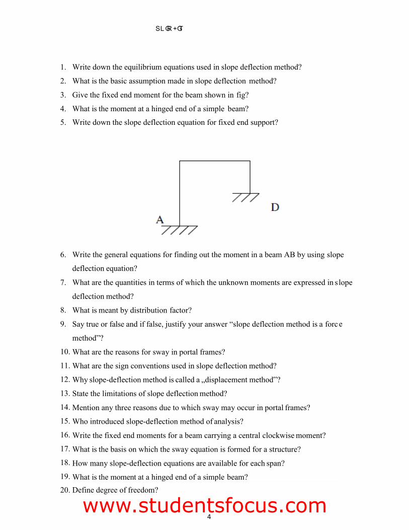
What are the quantities in terms of which the unknown moments are expressed in s
deflection method?
What is meant by distribution factor?
Say true or false and if false, justify your answer “slope deflection method is a forc
method”?
What are the reasons for sway in portal frames?
What are the sign conventions used in slope deflection method?
Why slope-deflection method is called a „displacement method‟?
State the limitations of slope deflection method?
Mention any three reasons due to which sway may occur in portal frames?
Who introduced slope-deflection method of analysis?
Write the fixed end moments for a beam carrying a central clockwise moment?
What is the basis on which the sway equation is formed for a structure?
How many slope-deflection equations are available for each span?
What is the moment at a hinged end of a simple beam?
UNIT –
IV 1. Write down the equilibrium equations used in slope deflection method?
2. What is the basic assumption made in slope deflection method?
3. Give the fixed end moment for the beam shown in fig?
4. What is the moment at a hinged end of a simple beam?
5. Write down the slope deflection equation for fixed end support?
6. Write the general equations for finding out the moment in a beam AB by using slope
7. lope
8.
9. e 10.
11.
12.
13.
14.
15.
16.
17.
18.
19.
20. Define degree of freedom?
FMCETSLGR% +% GT
www.studentsfocus.com
5
Define: Distribution factor?
Define: Stiffness factor?
Define: Flexural Rigidity of Beams?
Define the term „sway‟?
What are the situations where in sway will occur in portal frames?
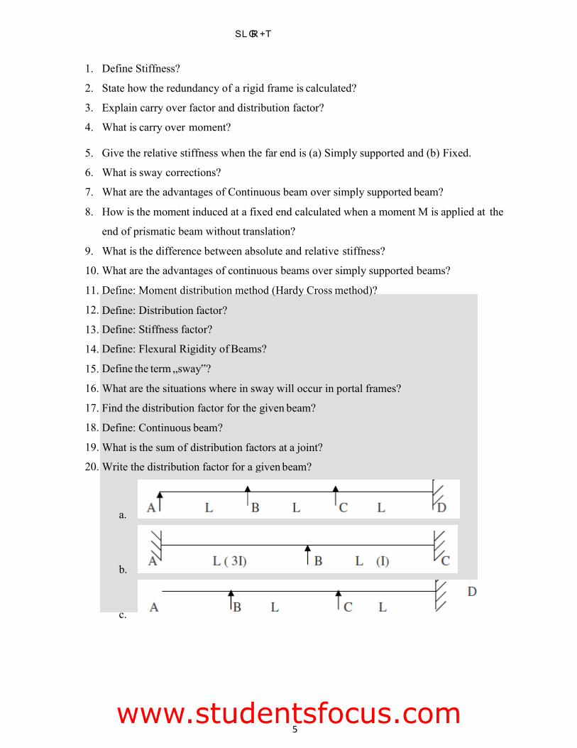
Find the distribution factor for the given beam?
Define: Continuous beam?
What is the sum of distribution factors at a joint?
Write the distribution factor for a given beam?
a.
b.
c.
UNIT- V 1. Define Stiffness?
2. State how the redundancy of a rigid frame is calculated?
3. Explain carry over factor and distribution factor?
4. What is carry over moment?
5. Give the relative stiffness when the far end is (a) Simply supported and (b) Fixed.
6. What is sway corrections?
7. What are the advantages of Continuous beam over simply supported beam?
8. How is the moment induced at a fixed end calculated when a moment M is applied at the
end of prismatic beam without translation?
9. What is the difference between absolute and relative stiffness?
10. What are the advantages of continuous beams over simply supported beams?
11. Define: Moment distribution method (Hardy Cross method)?
12.
13.
14.
15.
16.
17.
18.
19.
20.
FMCETSLGR% +% T
www.studentsfocus.com
6
PART – B
UNIT – I
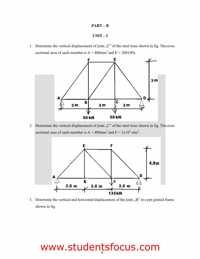
1. Determine the vertical displacement of joint „C‟ of the steel truss shown in fig. The cross
sectional area of each member is A = 400mm2 and E = 200 GPa.
2. Determine the vertical displacement of joint „C‟ of the steel truss shown in fig. The cross
sectional area of each member is A = 400mm2 and E = 2x105 mm2.
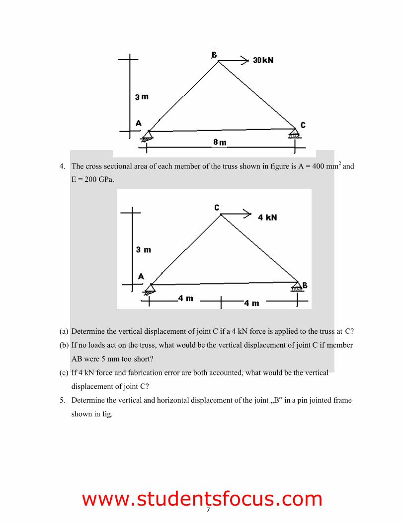
3. Determine the vertical and horizontal displacement of the joint „B‟ in a pin jointed frame
shown in fig.
FMCET
www.studentsfocus.com
7
4. The cross sectional area of each member of the truss shown in figure is A = 400 mm2 and
E = 200 GPa.
(a) Determine the vertical displacement of joint C if a 4 kN force is applied to the truss at C?
(b) If no loads act on the truss, what would be the vertical displacement of joint C if member
AB were 5 mm too short?
(c) If 4 kN force and fabrication error are both accounted, what would be the vertical
displacement of joint C?
5. Determine the vertical and horizontal displacement of the joint „B‟ in a pin jointed frame
shown in fig.
FMCET
www.studentsfocus.com
8
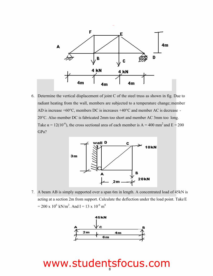
6. Determine the vertical displacement of joint C of the steel truss as shown in fig. Due to
radiant heating from the wall, members are subjected to a temperature change; member
AD is increase +60°C, members DC is increases +40°C and member AC is decrease -
20°C. Also member DC is fabricated 2mm too short and member AC 3mm too long.
Take α = 12(10-6), the cross sectional area of each member is A = 400 mm2 and E = 200 GPa?
7. A beam AB is simply supported over a span 6m in length. A concentrated load of 45kN is
acting at a section 2m from support. Calculate the deflection under the load point. Take E
= 200 x 106 kN/m2. And I = 13 x 10-6 m4
FMCET
www.studentsfocus.com
9
D B
l l/3
8. A beam AB is simply supported over a span 5m in length. A concentrated load of 30kN is acting at a section 1.25m from support. Calculate the deflection under the load point.
Take E = 200 x 106 kN/m2. And I = 13 x 10-6 m4
UNIT-II
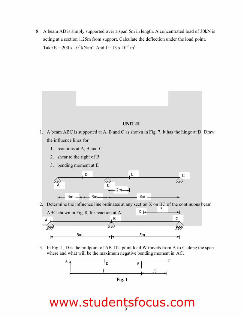
1. A beam ABC is supported at A, B and C as shown in Fig. 7. It has the hinge at D. Draw
the influence lines for
1. reactions at A, B and C
2. shear to the right of B
3. bending moment at E
D E C
A B 2m
4m 3m 8m
2. Determine the influence line ordinates at any section X on BC of the continuous beam x
ABC shown in Fig. 8, for reaction at A. X
A B C
5m 5m
3. In Fig. 1, D is the midpoint of AB. If a point load W travels from A to C along the span where and what will be the maximum negative bending moment in AC.
A C
Fig. 1
FMCET
www.studentsfocus.com
10
0.8 l
l 1.6 l
4. In Fig. 1 above, find the position and value of maximum negative shear.
5. For the beam in Fig. 1, sketch the influence line for reaction at B and mark the
ordinates.
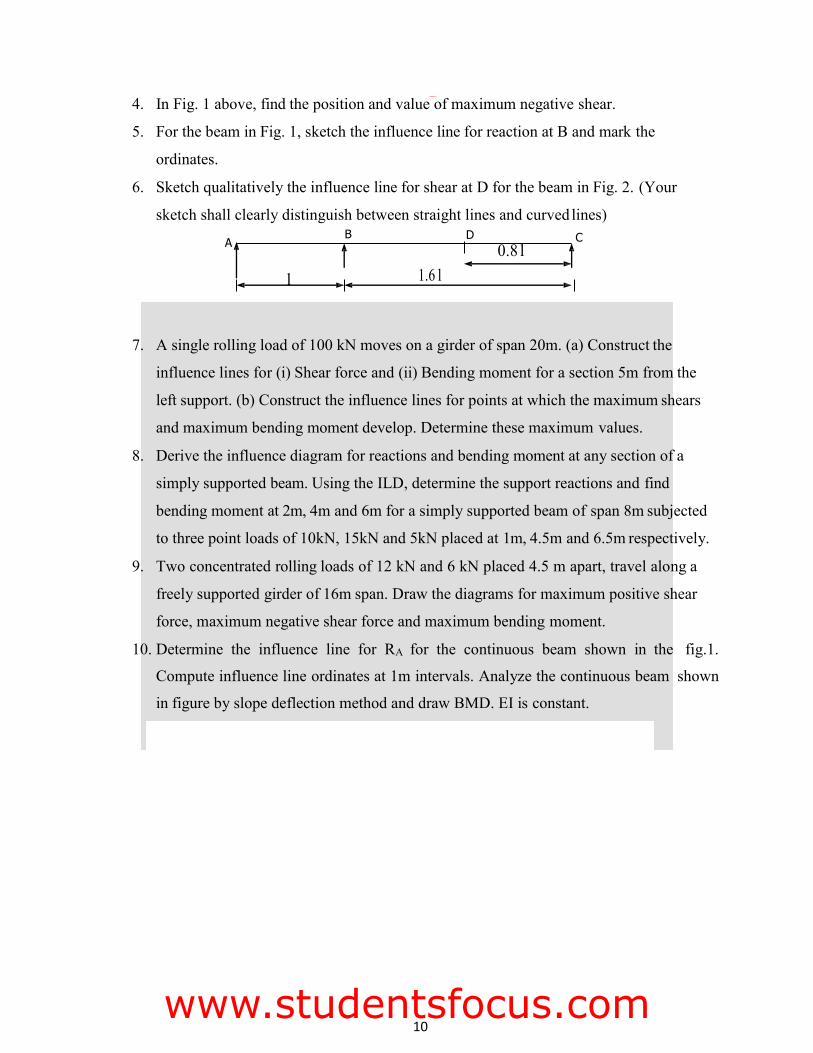
6. Sketch qualitatively the influence line for shear at D for the beam in Fig. 2. (Your
sketch shall clearly distinguish between straight lines and curved lines)
A B D C
7. A single rolling load of 100 kN moves on a girder of span 20m. (a) Construct the
influence lines for (i) Shear force and (ii) Bending moment for a section 5m from the
left support. (b) Construct the influence lines for points at which the maximum shears
and maximum bending moment develop. Determine these maximum values.
8. Derive the influence diagram for reactions and bending moment at any section of a
simply supported beam. Using the ILD, determine the support reactions and find
bending moment at 2m, 4m and 6m for a simply supported beam of span 8m subjected
to three point loads of 10kN, 15kN and 5kN placed at 1m, 4.5m and 6.5m respectively.
9. Two concentrated rolling loads of 12 kN and 6 kN placed 4.5 m apart, travel along a
freely supported girder of 16m span. Draw the diagrams for maximum positive shear
force, maximum negative shear force and maximum bending moment.
10. Determine the influence line for RA for the continuous beam shown in the fig.1.
Compute influence line ordinates at 1m intervals. Analyze the continuous beam shown
in figure by slope deflection method and draw BMD. EI is constant.
FMCET
www.studentsfocus.com
11
UNIT-III
1. A three hinged parabolic arch of span 100m and rise 20m carries a uniformly
distributed load of 2KN/m length on the right half as shown in the figure. Determine
the maximum bending moment in the arch.
2. A two hinged parabolic arch of span 20m and rise 4m carries a uniformly distributed
load of 5t/m on the left half of span as shown in figure. The moment of inertia I of the
arch section at any section at any point is given by I = I0 sec where = inclination of
the tangent at the point with the horizontal and I0 is the moment of inertia at the crown.
Find
(a) The reactions at the supports (b) The position and (c) The value of the maximum bending moment in the arch.
3. A three hinged symmetric parabolic arch hinged at the crown and springing, has a span
of 15m with a central rise of 3m. It carries a distributed load which varies uniformly
form 32kN/m (horizontal span) over the left hand half of the span. Calculate the normal
thrust; shear force and bending moment at 5 meters from the left end hinge.
4. A two hinged parabolic arch of span 30m and central rise 5m carries a uniformly
distributed load of 20kN/m over the left half of the span. Determine the position and
value of maximum bending moment. Also find the normal thrust and radial shear force
at the section. Assume that the moment of inertia at a section varies as secant of the
inclination at the section.
5. A three hinged parabolic arch, hinged at the crown and springing has a horizontal of
15m with a central rise of 3m. If carries a udl of 40kN/m over the left hand of the span.
FMCET
www.studentsfocus.com
12
3m
.
Calculate normal thrust, radial shear and bending moment at 5m from the left hand
hinge.
6. A parabolic two hinged arch has a span L and central rise „r‟. Calculate the horizontal
thrust at the hinges due to UDL „w‟ over the whole span.
7. Derive an expression for the horizontal thrust of a two hinged parabolic arch. Assume, I
= Io Sec
8. A three hinged parabolic arch of span 20 m and rise 4m carries a UDL of 20 kN/m over
the left half of the span. Draw the BMD.
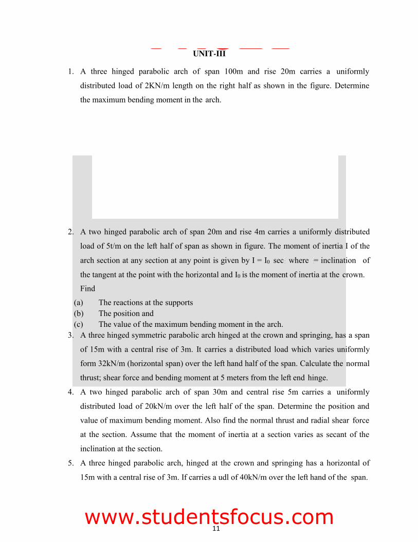
9. A parabolic 3 hinged arch shown in fig. 9 carries loads as indicated. Determine (i) resultant reactions at the 2 supports (ii) (ii) bending moment, shear (radial) and normal thrust at D, 5m from A.
30 kN 25 kN/m
20 kN 4m 3m
C D
5m
5m
A B
° 20m
10. A symmetrical parabolic arch spans 40m and central rise 10m is hinged to the
abutments and the crown. It carries a linearly varying load of 300 N/M at each of the
abutments to zero at the crown. Calculate the horizontal and vertical reactions at the
abutments and the position and magnitude of maximum bending moment.
11. A three hinged stiffening girder of a suspension bridge of span 100m is subjected to
two points loads of 200 kN and 300 kN at a distance of 25 m and 50 m from the left
end. Find the shear force and bending moment for the girder.
FMCET
www.studentsfocus.com
13
12. In a simply supported girder AB of span 20m, determine the maximum bending
moment and maximum shear force at a section 5m from A, due to passage of a
uniformly distributed load of intensity 20 kN/m, longer than the span.
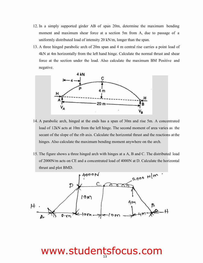
13. A three hinged parabolic arch of 20m span and 4 m central rise carries a point load of
4kN at 4m horizontally from the left hand hinge. Calculate the normal thrust and shear
force at the section under the load. Also calculate the maximum BM Positive and
negative.
14. A parabolic arch, hinged at the ends has a span of 30m and rise 5m. A concentrated
load of 12kN acts at 10m from the left hinge. The second moment of area varies as the
secant of the slope of the rib axis. Calculate the horizontal thrust and the reactions at the
hinges. Also calculate the maximum bending moment anywhere on the arch.
15. The figure shows a three hinged arch with hinges at a A, B and C. The distributed load
of 2000N/m acts on CE and a concentrated load of 4000N at D. Calculate the horizontal
thrust and plot BMD.
FMCET
www.studentsfocus.com
14
UNIT-IV
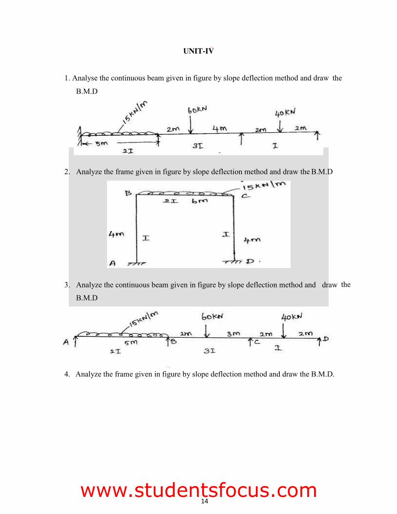
1. Analyse the continuous beam given in figure by slope deflection method and draw the
B.M.D
the
4. Analyze the frame given in figure by slope deflection method and draw the B.M.D.
2. Analyze the frame given in figure by slope deflection method and draw the B.M.D
3. Analyze the continuous beam given in figure by slope deflection method and draw
B.M.D
FMCET
www.studentsfocus.com
15
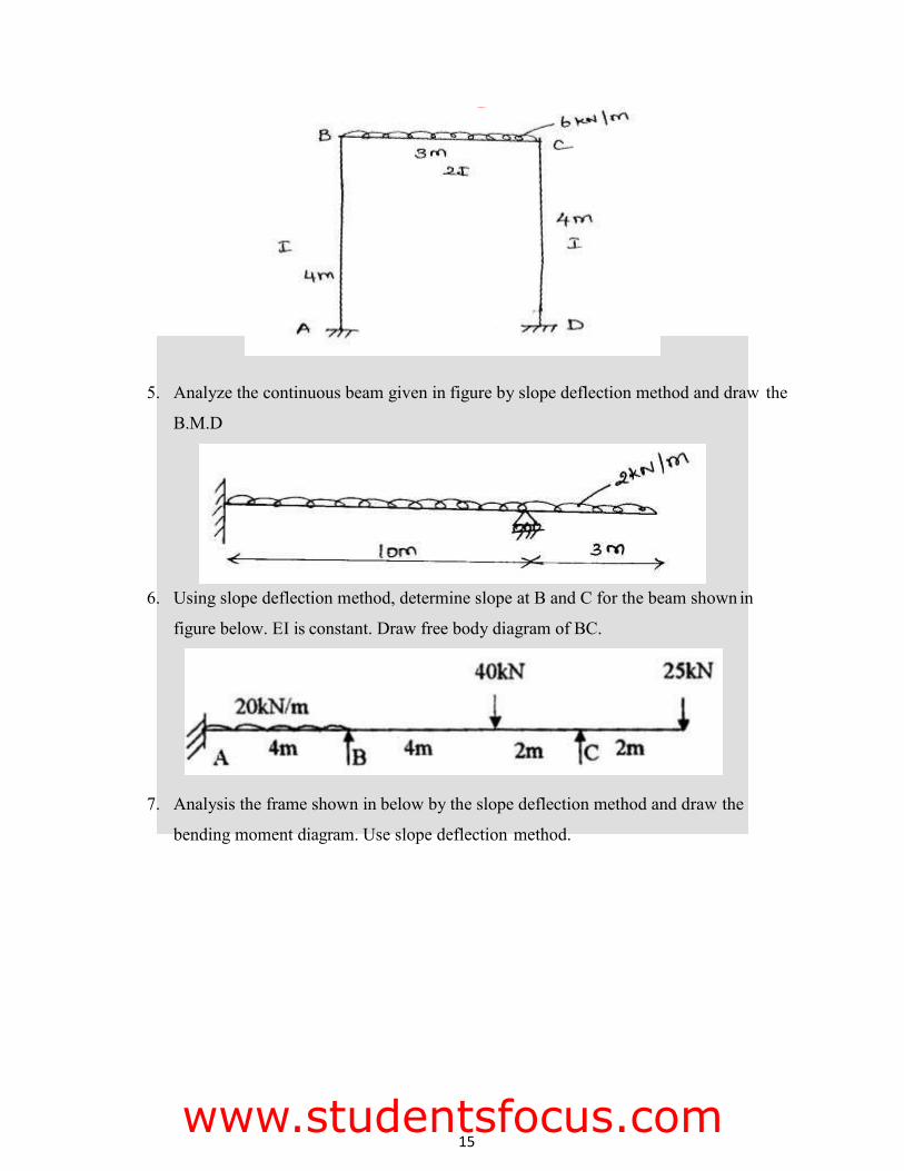
5. Analyze the continuous beam given in figure by slope deflection method and draw the
B.M.D
6. Using slope deflection method, determine slope at B and C for the beam shown in
figure below. EI is constant. Draw free body diagram of BC.
7. Analysis the frame shown in below by the slope deflection method and draw the
bending moment diagram. Use slope deflection method.
FMCET
www.studentsfocus.com
16
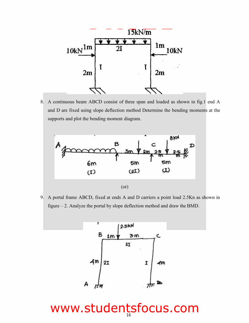
8. A continuous beam ABCD consist of three span and loaded as shown in fig.1 end A
and D are fixed using slope deflection method Determine the bending moments at the
supports and plot the bending moment diagram.
(or)
9. A portal frame ABCD, fixed at ends A and D carriers a point load 2.5Kn as shown in
figure – 2. Analyze the portal by slope deflection method and draw the BMD.
FMCET
www.studentsfocus.com
17
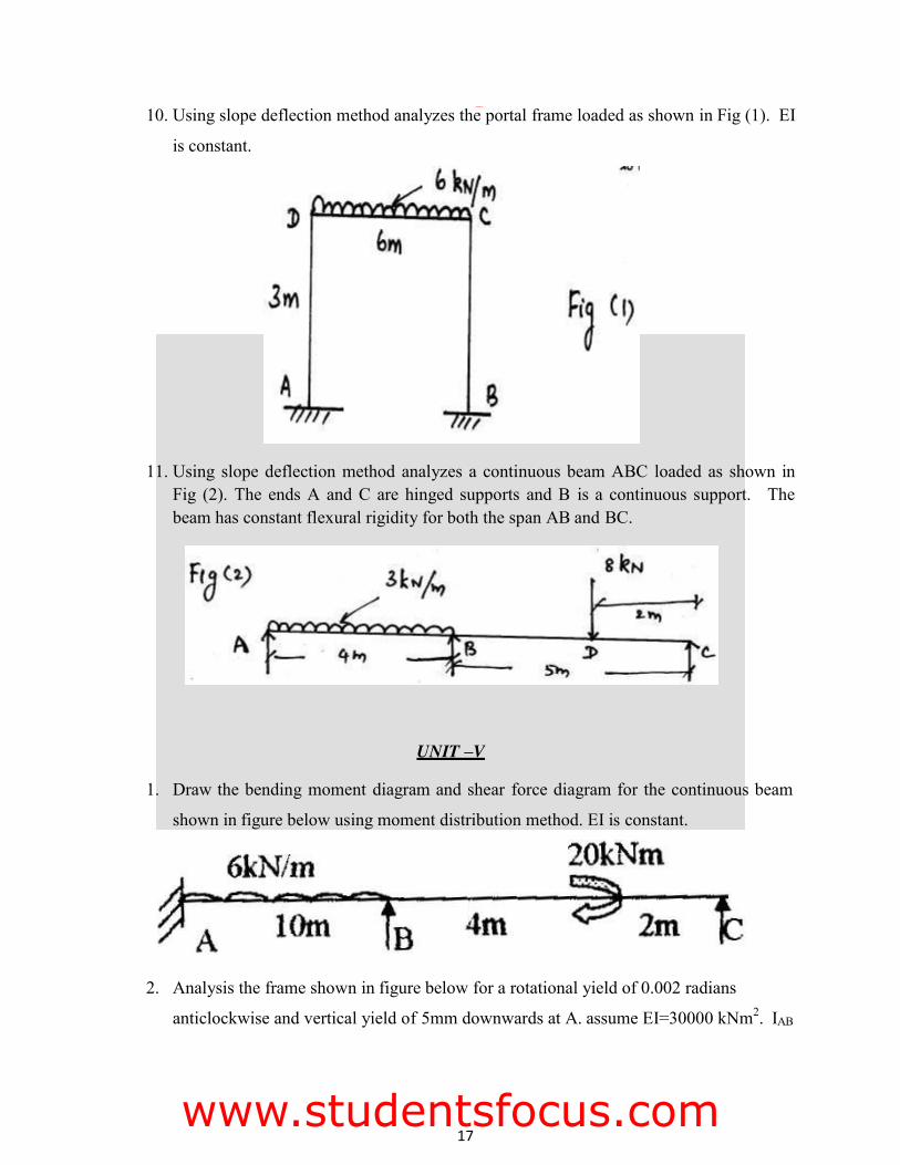
10. Using slope deflection method analyzes the portal frame loaded as shown in Fig (1). EI
is constant.
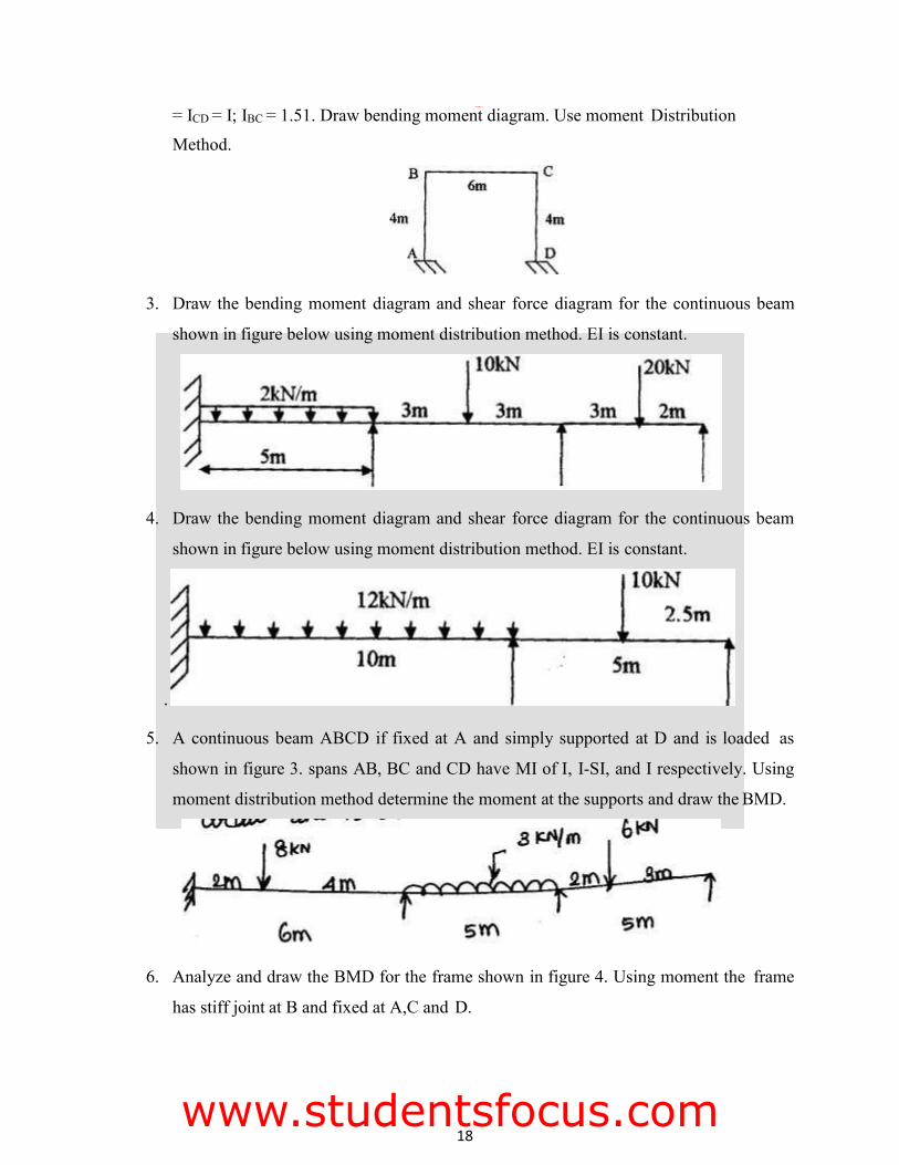
11. Using slope deflection method analyzes a continuous beam ABC loaded as shown in Fig (2). The ends A and C are hinged supports and B is a continuous support. The beam has constant flexural rigidity for both the span AB and BC.
UNIT –V
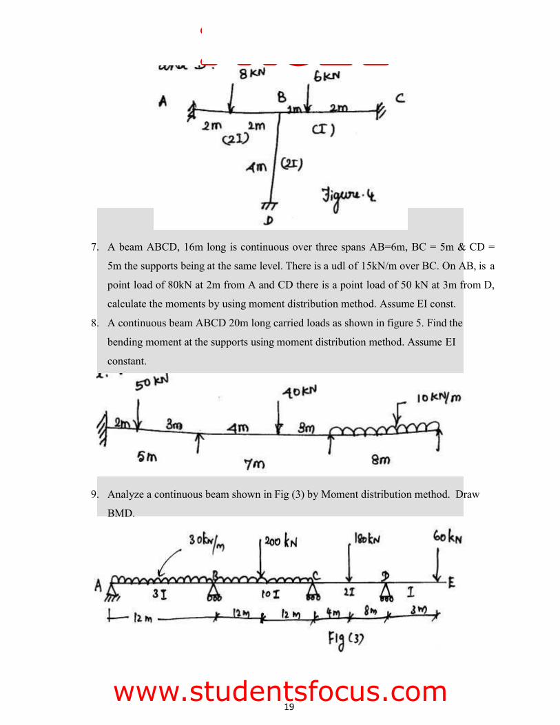
1. Draw the bending moment diagram and shear force diagram for the continuous beam
shown in figure below using moment distribution method. EI is constant.
2. Analysis the frame shown in figure below for a rotational yield of 0.002 radians
anticlockwise and vertical yield of 5mm downwards at A. assume EI=30000 kNm2. IAB
FMCET
www.studentsfocus.com
18
= ICD = I; IBC = 1.51. Draw bending moment diagram. Use moment Distribution
Method.
3. Draw the bending moment diagram and shear force diagram for the continuous beam
shown in figure below using moment distribution method. EI is constant.
4. Draw the bending moment diagram and shear force diagram for the continuous beam
shown in figure below using moment distribution method. EI is constant.
.
5. A continuous beam ABCD if fixed at A and simply supported at D and is loaded as
shown in figure 3. spans AB, BC and CD have MI of I, I-SI, and I respectively. Using
moment distribution method determine the moment at the supports and draw the BMD.
6. Analyze and draw the BMD for the frame shown in figure 4. Using moment the frame
has stiff joint at B and fixed at A,C and D.
FMCET
www.studentsfocus.com
19
7. A beam ABCD, 16m long is continuous over three spans AB=6m, BC = 5m & CD =
5m the supports being at the same level. There is a udl of 15kN/m over BC. On AB, is a
point load of 80kN at 2m from A and CD there is a point load of 50 kN at 3m from D,
calculate the moments by using moment distribution method. Assume EI const.
8. A continuous beam ABCD 20m long carried loads as shown in figure 5. Find the
bending moment at the supports using moment distribution method. Assume EI
constant.
9. Analyze a continuous beam shown in Fig (3) by Moment distribution method. Draw
BMD.
FMCET
www.studentsfocus.com
20
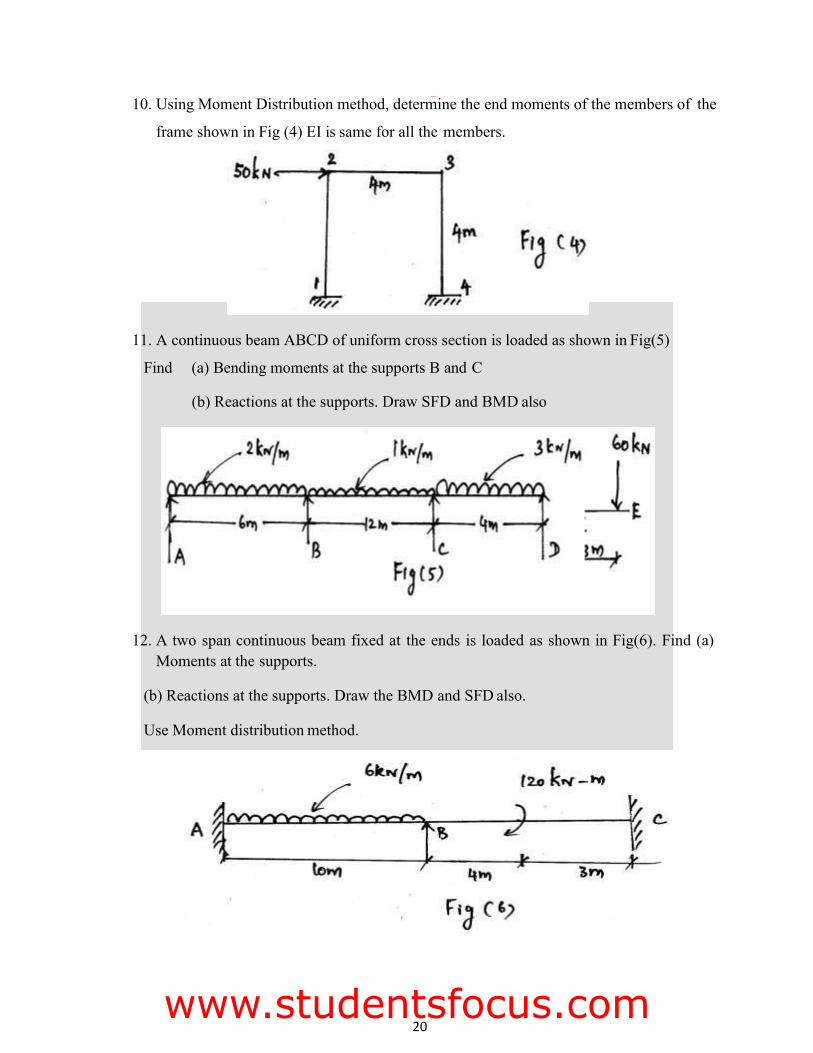
10. Using Moment Distribution method, determine the end moments of the members of the
frame shown in Fig (4) EI is same for all the members.
11. A continuous beam ABCD of uniform cross section is loaded as shown in Fig(5)
Find (a) Bending moments at the supports B and C
(b) Reactions at the supports. Draw SFD and BMD also
12. A two span continuous beam fixed at the ends is loaded as shown in Fig(6). Find (a) Moments at the supports.
(b) Reactions at the supports. Draw the BMD and SFD also.
Use Moment distribution method.
FMCET
www.studentsfocus.com
21
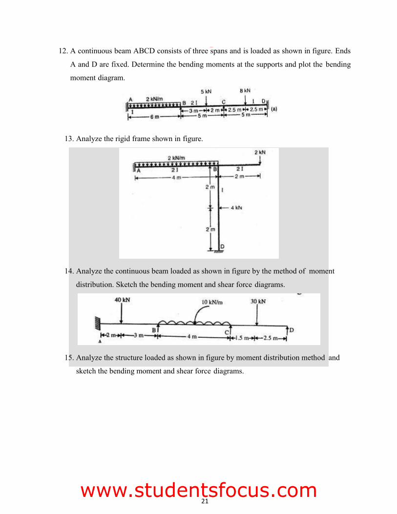
12. A continuous beam ABCD consists of three spans and is loaded as shown in figure. Ends
A and D are fixed. Determine the bending moments at the supports and plot the bending
moment diagram.
13. Analyze the rigid frame shown in figure.
14. Analyze the continuous beam loaded as shown in figure by the method of moment
distribution. Sketch the bending moment and shear force diagrams.
15. Analyze the structure loaded as shown in figure by moment distribution method and
sketch the bending moment and shear force diagrams.
FMCET
www.studentsfocus.com
22
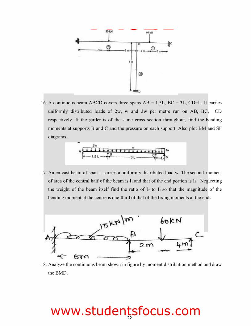
16. A continuous beam ABCD covers three spans AB = 1.5L, BC = 3L, CD=L. It carries
uniformly distributed loads of 2w, w and 3w per metre run on AB, BC, CD
respectively. If the girder is of the same cross section throughout, find the bending
moments at supports B and C and the pressure on each support. Also plot BM and SF
diagrams.
17. An en-cast beam of span L carries a uniformly distributed load w. The second moment
of area of the central half of the beam is I1 and that of the end portion is I2. Neglecting
the weight of the beam itself find the ratio of I2 to I1 so that the magnitude of the
bending moment at the centre is one-third of that of the fixing moments at the ends.
18. Analyze the continuous beam shown in figure by moment distribution method and draw
the BMD.
FMCET
www.studentsfocus.com
23
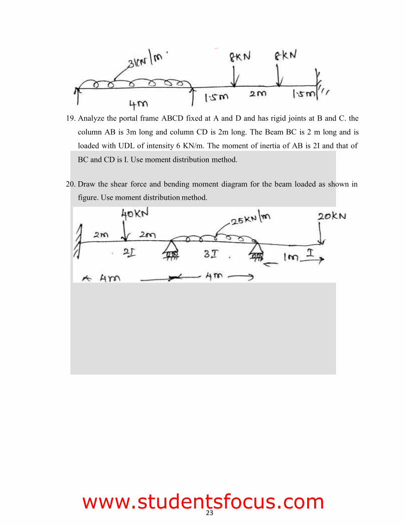
BC and CD is I. Use moment distribution method.
20. Draw the shear force and bending moment diagram for the beam loaded as shown in
figure. Use moment distribution method.
19. Analyze the portal frame ABCD fixed at A and D and has rigid joints at B and C. the
column AB is 3m long and column CD is 2m long. The Beam BC is 2 m long and is
loaded with UDL of intensity 6 KN/m. The moment of inertia of AB is 2I and that of
FMCET
www.studentsfocus.com

![INDEX [studentsfocus.com]studentsfocus.com/wp-content/uploads/anna_univ/CSE/4SEM/CS6412... · 15 Square and Cube program, ... operation of two byte numbers. APPARATUS REQUIRED: SL.N](https://static.fdocuments.net/doc/165x107/5aa283947f8b9ab4208d2861/index-square-and-cube-program-operation-of-two-byte-numbers-apparatus.jpg)


![SRI VIDYA COLLEGE OF ENGINEERING AND ...studentsfocus.com/notes/anna_university/2017/ECE/5th sem...COURSE MATERIAL[LECTURE NOTES] EC6501/DC UNIT 3 Page 32 STUDENTSFOCUS.COM SRI VIDYA](https://static.fdocuments.net/doc/165x107/5e6c346c8d66cf235d5b40cf/sri-vidya-college-of-engineering-and-sem-course-materiallecture-notes-ec6501dc.jpg)


![INDEX [studentsfocus.com]studentsfocus.com/notes/anna_university/IT/4SEM... · cs6412 – microprocessor and microcontroller lab dept of cse 2 expt.no name of the experiment page](https://static.fdocuments.net/doc/165x107/5afd184c7f8b9a323491255e/index-microprocessor-and-microcontroller-lab-dept-of-cse-2-exptno-name.jpg)


