Dent Assessment and Managementballots.api.org/pipeline/RP1183_1Ed_DentMgmt_4893.pdfThis RP is...
94
This document is not an API Standard; it is under consideration within an API technical committee but has not received all approvals required to become an API Standard. It shall not be reproduced or circulated or quoted, in whole or in part, outside of API committee activities except with the approval of the Chairman of the committee having jurisdiction and staff of the API Standards Dept. Copyright API. All rights reserved. 1 Dent Assessment and Management API RECOMMENDED PRACTICE 1183 FIRST EDITION, XXXX 2019
Transcript of Dent Assessment and Managementballots.api.org/pipeline/RP1183_1Ed_DentMgmt_4893.pdfThis RP is...

This document is not an API Standard; it is under consideration within an API technical committee but has not received all approvals required to become an API Standard. It shall not be reproduced or circulated or quoted, in whole or in part, outside of API committee activities except with the approval of the Chairman of the committee having jurisdiction and staff of the API Standards Dept. Copyright API. All rights reserved.
1
Dent Assessment and Management API RECOMMENDED PRACTICE 1183 FIRST EDITION, XXXX 2019

This document is not an API Standard; it is under consideration within an API technical committee but has not received all approvals required to become an API Standard. It shall not be reproduced or circulated or quoted, in whole or in part, outside of API committee activities except with the approval of the Chairman of the committee having jurisdiction and staff of the API Standards Dept. Copyright API. All rights reserved.
2
Foreward
Nothing contained in any API publication is to be construed as granting any right, by implication or otherwise, for the manufacture, sale, or use of any method, apparatus, or product covered by letters patent. Neither should anything contained in the publication be construed as insuring anyone against liability for infringement of letters patent.
Shall: As used in a standard, “shall” denotes a minimum requirement in order to conform to the specification.
Should: As used in a standard, “should” denotes a recommendation or that which is advised but not required in order to conform to the specification.
This document was produced under API standardization procedures that ensure appropriate notification and participation in the developmental process and is designated as an API standard. Questions concerning the interpretation of the content of this publication or comments and questions concerning the procedures under which this publication was developed should be directed in writing to the Director of Standards, American Petroleum Institute, 1220 L Street, NW, Washington, DC 20005. Requests for permission to reproduce or translate all or any part of the material published herein should also be addressed to the director.
Generally, API standards are reviewed and revised, reaffirmed, or withdrawn at least every five years. A one-time extension of up to two years may be added to this review cycle. Status of the publication can be ascertained from the API Standards Department, telephone (202) 682-8000. A catalog of API publications and materials is published annually by API, 1220 L Street, NW, Washington, DC 20005.
Suggested revisions are invited and should be submitted to the Standards Department, API, 1220 L Street, NW, Washington, DC 20005, [email protected].

This document is not an API Standard; it is under consideration within an API technical committee but has not received all approvals required to become an API Standard. It shall not be reproduced or circulated or quoted, in whole or in part, outside of API committee activities except with the approval of the Chairman of the committee having jurisdiction and staff of the API Standards Dept. Copyright API. All rights reserved.
3
TABLE OF CONTENTS 1 Scope ..................................................................................................................................................... 6
1.1 References .................................................................................................................................... 8 2 Normative References ........................................................................................................................... 8 3 Definitions and Acronyms ...................................................................................................................... 9
3.1 Terms and Definitions ................................................................................................................... 9 Anomaly .................................................................................................................................... 9 Assessment ............................................................................................................................... 9 Buckle ........................................................................................................................................ 9 Characteristic Lengths .............................................................................................................. 9 Coincident Feature .................................................................................................................... 9 Constrained Dent ...................................................................................................................... 9 Corrosion ................................................................................................................................... 9 Defect ........................................................................................................................................ 9 Dent ........................................................................................................................................... 9
Dent Apex ............................................................................................................................ 10 Dent Profile .......................................................................................................................... 10 Electric Resistance Welded Pipe (ERW) ............................................................................ 10 Engineering Critical Assessment (ECA).............................................................................. 10 Fatigue Life Reduction ........................................................................................................ 10 Fitness-For-Service (FFS) Assessment .............................................................................. 10 Geometric Magnetic Anomaly ............................................................................................. 10 Girth Weld ........................................................................................................................... 10 Gouge .................................................................................................................................. 10 In-Line Inspection (ILI) ........................................................................................................ 10 ILI System ........................................................................................................................... 10 Imperfection ......................................................................................................................... 10 Indenter ............................................................................................................................... 11 Integrity Assessment ........................................................................................................... 11 Interacting Defect ................................................................................................................ 11 Long Seam Misalignment .................................................................................................... 11 Limit State ........................................................................................................................... 11 Long Seam Weld ................................................................................................................. 11 Maximum Operating Pressure (MOP) ................................................................................. 11 Metal Loss ........................................................................................................................... 11 Mill Test Report ................................................................................................................... 11 Mitigation Or Mitigative Measures ....................................................................................... 11 Multi Peak Dent ................................................................................................................... 11 Operator .............................................................................................................................. 11 Ovality ................................................................................................................................. 11 Plain Dent ............................................................................................................................ 12 Out Of Roundness............................................................................................................... 12 Pipe Grade .......................................................................................................................... 12 Pressure Spectrum.............................................................................................................. 12 Preventive Measures .......................................................................................................... 12 Rainflow Counting ............................................................................................................... 12 Rebound .............................................................................................................................. 12 Remediation Or Remedial Action ........................................................................................ 12 Rerounding .......................................................................................................................... 12 Restrained Dent .................................................................................................................. 12 Restraint Parameter ............................................................................................................ 12 Ripple .................................................................................................................................. 12 Risk ..................................................................................................................................... 12 Risk Assessment ................................................................................................................. 12 Screening ............................................................................................................................ 13 Shape Parameter ................................................................................................................ 13

This document is not an API Standard; it is under consideration within an API technical committee but has not received all approvals required to become an API Standard. It shall not be reproduced or circulated or quoted, in whole or in part, outside of API committee activities except with the approval of the Chairman of the committee having jurisdiction and staff of the API Standards Dept. Copyright API. All rights reserved.
4
Spectrum Severity ............................................................................................................... 13 Wrinkle ................................................................................................................................ 13
3.2 Acronyms and Abbreviations ...................................................................................................... 13 4 Guiding Principles ................................................................................................................................ 14
4.1 Exclusions ................................................................................................................................... 15 4.2 Competence ................................................................................................................................ 15 4.3 What Is a Dent Feature ............................................................................................................... 15
Common Dent Types .............................................................................................................. 16 Dent Formation Process ......................................................................................................... 16 Coincident Features ................................................................................................................ 17
4.4 References .................................................................................................................................. 18 5 Dent Integrity Management Process ................................................................................................... 18
5.1 Recommended Practice Overview .............................................................................................. 18 5.2 Dent Integrity Management Process Overview ........................................................................... 19
Collect And Integrate Data To Characterize Dents ................................................................. 20 Screening And Assessment Of Data....................................................................................... 21 Dent Mitigation And Remediation ............................................................................................ 22 Continuous Improvement .......................................................... Error! Bookmark not defined.
5.3 Significant Parameters ................................................................................................................ 23 Pipeline Service....................................................................................................................... 25 Coincident Features ................................................................................................................ 25
5.4 References .................................................................................................................................. 25 6 Pipeline Dent and Operational Condition Characterization ................................................................. 25
6.1 Pipe and Dent Geometry ............................................................................................................. 26 6.2 Dent Geometry Profile Characterization ..................................................................................... 26 6.3 Identification of Dent Features Considering In-Line Inspection Data.......................................... 31 6.4 Restraint Condition ...................................................................................................................... 32
Restraint Condition By Clock Position Treatment ................................................................... 32 Restraint Parameter ................................................................................................................ 32
6.5 Coincident Features and Interacting Defects .............................................................................. 33 Weld Characterization And Interaction.................................................................................... 33 Corrosion Characterization And Interaction ............................................................................ 34 Gouge Characterization And Interaction ................................................................................. 35 Crack Characterization And Interaction .................................................................................. 35 Lamination Interaction ............................................................................................................. 36 Multiple Dent Interaction ......................................................................................................... 36
6.6 Operating Condition Severity ...................................................................................................... 36 Maximum Pressure At The Dent Location .............................................................................. 36 Operational Pressure Time History Data Gathering And Frequency ...................................... 36 Operational Cyclic Pressure Characterization ........................................................................ 37 Spectrum Severity Indictor (SSI) ............................................................................................. 40
6.7 Material Properties ...................................................................................................................... 41 Material Strength ..................................................................................................................... 41 Material Toughness ................................................................................................................. 41 Fatigue Crack Growth Rate ..................................................................................................... 42
6.8 References .................................................................................................................................. 42 7 Dent Feature Screening ....................................................................................................................... 42
7.1 Qualitative Risk Screening .......................................................................................................... 43 7.2 Indentation Crack Formation Strain ............................................................................................ 46 7.3 Pressure Increase Induced Damage Screening ......................................................................... 46 7.4 Fatigue Life Dent Screening ........................................................................................................ 47
Operational Severity Fatigue Life Screening .......................................................................... 47 Shallow Dent Spectrum Severity Indicator Fatigue Life Screening ........................................ 48 Shallow Dent And Operational Pressure Spectrum Fatigue Life Screening ........................... 49
7.5 Finite Element Modelling Screening ........................................................................................... 51 7.6 References .................................................................................................................................. 51

This document is not an API Standard; it is under consideration within an API technical committee but has not received all approvals required to become an API Standard. It shall not be reproduced or circulated or quoted, in whole or in part, outside of API committee activities except with the approval of the Chairman of the committee having jurisdiction and staff of the API Standards Dept. Copyright API. All rights reserved.
5
8 Fitness-For-Service Assessment Approaches .................................................................................... 53 8.1 Dent Pressure Increase Induced Damage Assessment ............................................................. 53
Dent Gouge Pressure Increase Induced Damage Assessment ............................................. 53 Ductile Failure Damage Indicator (DFDI) Or ASME B31.8 – Crack Formation Potential During
Indentation ........................................................................................................................................... 55 8.2 Dent Fatigue Life Assessment .................................................................................................... 57
Dent Fatigue Life Assessment Overview ................................................................................ 57 Level 1 - Single Peak Dent Fatigue Response Severity Ranking ........................................... 58 Level 2 - Single Peak Dent Fatigue Life Assessment ............................................................. 58 PRCI Level 1 and Level 2 Shape Factor and Shape Parameter Life Assessment ................. 60 Level 3 – Detailed Finite Element Modelling for Dent Fatigue Life Assessment .................... 62
8.3 Safety Factors / Conservatism .................................................................................................... 63 8.4 Probabilistic Assessment ............................................................................................................ 63 8.5 References .................................................................................................................................. 64
9 Field Guidance ..................................................................................................................................... 65 9.1 Excavation ................................................................................................................................... 65
Operating Pressure Reduction For Excavation ....................................................................... 65 Unsupported Span .................................................................................................................. 65
9.2 In-Service Monitoring and Inspection .......................................................................................... 66 In-Service Monitoring .............................................................................................................. 66 Visual Inspection And Field Measurement .............................................................................. 66
9.3 Documentation and Feedback .................................................................................................... 67 9.4 Cutting and Removal ................................................................................................................... 67
Pipeline Cutting And Documentation ...................................................................................... 67 Preparation For Shipment ....................................................................................................... 68
9.5 References .................................................................................................................................. 68 10 Mitigative and Repair Action Guidance ................................................................................................ 69
10.1 Mitigative Actions ........................................................................................................................ 69 Pressure Reduction ............................................................................................................. 69 Re-Evaluation Of Operational Pressure History ................................................................. 69
10.2 Managing Pressure Cycles ......................................................................................................... 69 10.3 Coincident Feature and Interacting Defect Mitigation ................................................................. 70
Corrosion Feature Mitigation ............................................................................................... 70 Crack Feature Mitigation ..................................................................................................... 70 Weld Feature Mitigation ...................................................................................................... 70
10.4 Repair Methods ........................................................................................................................... 71 General ................................................................................................................................ 71 Replace As A Cylinder ........................................................................................................ 71 Grinding / Buffing................................................................................................................. 71 Full Encirclement Sleeves ................................................................................................... 72 Composite Sleeves And Wraps .......................................................................................... 72 Compression Sleeves ......................................................................................................... 73 Mechanical Bolt-On Clamps ................................................................................................ 73 Hot Tapping ......................................................................................................................... 73 Repair Method Applicability Guidance ................................................................................ 73
10.5 References .................................................................................................................................. 74 Appendix A – Worked Example Calculations.............................................................................................. 75 Appendix B – Dent Crack Initiation Surface, Location, Orientation and FormError! Bookmark not defined. Appendix C – Field Guidance Listing .......................................................................................................... 83 Appendix D – Effect if Axial Loads on Dents .............................................................................................. 87 Appendix E - Capabilities of In-line Inspection Technologies for Plain Dents and Specific Types of Coincident Features and Interacting Defects .............................................................................................. 88 Appendix F – PRCI Dent Fatigue Shape Parameters ................................................................................ 91 Appendix G - Scaling Factors for Unrestrained Dent Shape Factors in Equation 12 ................................. 93

This document is not an API Standard; it is under consideration within an API technical committee but has not received all approvals required to become an API Standard. It shall not be reproduced or circulated or quoted, in whole or in part, outside of API committee activities except with the approval of the Chairman of the committee having jurisdiction and staff of the API Standards Dept. Copyright API. All rights reserved.
6
Introduction
This Recommended Practice (RP) provides guidance to the pipeline industry for assessing and managing dents that are present in pipeline systems as a result of mechanical contact by rocks, machinery, or other forces. Emphasis is placed on conditions where dents are either closely aligned or coincident with other threats, and the applicable data screening and assessment methods available to guide decision making on mitigation, remediation, or repair. Additional emphasis is placed on the pipeline operational parameters and the influence of those parameters on dent fatigue.
The RP presents comprehensive guidance for developing a dent assessment and management program including:
1) Selecting suitable methods for inspecting and characterizing the condition of the pipeline with respect to dents;
2) Establishing data screening processes to evaluate dents relative to extent and degree of deformation and operational severity;
3) Provide response criteria for dents based on in-line inspection results based on the dent shape and profile;
4) Applying engineering assessment methods to evaluate fitness-for-service of dents including reassessment interval;
5) Presenting remediation and repair options to address dents;
6) Developing preventive and mitigative measures for dents in lieu of, or in addition to, periodic integrity assessment, including pressure reductions and pressure cycle management.
This document provides guidance on elements of an engineering critical assessment for dent features to determine fitness-for-service.
This RP may be used to supplement requirements included in 49 CFR 195.452, 49 CFR 192.933, CSA Z662, SOR/99-294, and other integrity management codes and standards. The RP provides the process and tools to conduct screening and engineering assessment (e.g., fitness for purpose, engineering critical assessment) for mechanical damage features. These processes and tools represent revised criteria for the assessment of mechanical damage accounting for the factors that lead to pipeline failures caused by dents.
While this RP is generally applicable to all pipeline systems, it does not:
- consider detailed requirements for new construction to prevent dents. For information on this one could reference API 1169 and API 1177
- provide guidance on prevention of mechanical damage in-service
- outline design considerations for preventing and limiting susceptibility to mechanical damage or dents
- provide guidance on the assessment of wrinkles, ripples, long seam misalignment, ovalized bends, buckles, and
- explicitly identify the differences between onshore and offshore pipeline systems.
This RP is intended for use by pipeline operators to support planning, developing, implementing, and improving a pipeline dent management program. This RP is closely aligned with the API 1160 RP for liquid hazardous pipeline integrity management under 49 CFR 195.452 of the U.S. federal pipeline safety regulations. It is also equally applicable to natural gas pipeline systems (e.g., those governed by 49 CFR 192.933), and is written as a broadly applicable framework for both hazard liquid and gas pipelines located in any location or under any jurisdiction. This RP augments API 1160 in the development of integrity management programs required under U.S. federal pipeline safety regulations. Dent management is one element of an effective and robust pipeline integrity management program.

This document is not an API Standard; it is under consideration within an API technical committee but has not received all approvals required to become an API Standard. It shall not be reproduced or circulated or quoted, in whole or in part, outside of API committee activities except with the approval of the Chairman of the committee having jurisdiction and staff of the API Standards Dept. Copyright API. All rights reserved.
7
This RP provides guidance based upon an understanding of the current state of industry knowledge and expertise on managing mechanical damage features in pipelines. Research to improve upon the current state of knowledge continues and it is expected that this RP will be updated to incorporate future enhancements in industry knowledge and expertise.
This is the first edition of RP 1183 and the development of guidance that specifically addresses dent assessment and management; a prior API Publication, API Publication 1156 [1.3], described the effects of dents on liquid petroleum pipelines but was issued prior to the hazardous liquids pipeline integrity management rule. The RP provides the current industry understanding of dent formation and post-formation behavior and response to environmental and operational factors. This understanding is based on the practical experience of pipeline operators that have been managing dents under the pipeline integrity management regulations included in 49 CFR §192 and §195 and integration of over 20 years of research on dents through work completed by the pipeline industry.
This RP provides guidance based upon an understanding of the current state of industry knowledge and expertise on managing mechanical damage features in pipelines. This RP may be used to supplement requirements included in 49 CFR 195.452, 49 CFR 192.933, CSA Z662 and other integrity management codes and standards. The RP provides the process and tools to conduct screening and engineering assessment (e.g., fitness for purpose, engineering critical assessment) for mechanical damage features. These processes and tools represent revised criteria for the assessment of mechanical damage accounting for the factors that lead to pipeline failures caused by dents.

This document is not an API Standard; it is under consideration within an API technical committee but has not received all approvals required to become an API Standard. It shall not be reproduced or circulated or quoted, in whole or in part, outside of API committee activities except with the approval of the Chairman of the committee having jurisdiction and staff of the API Standards Dept. Copyright API. All rights reserved.
8
1 Scope
This recommended practice (RP) is applicable to any pipeline system used to transport hazardous liquid or natural gas. This RP includes detailed technical discussion on dent formation, strain and fatigue, and failure modes and mechanisms. These details are provided to give pipeline operators the information and knowledge necessary to make informed integrity management decisions regarding the management of dents on their systems.
Mechanisms that promote denting are discussed, methods to inspect dents are described, and approaches and tools to estimate dent fitness-for-service (i.e., pressure increase induced damage and fatigue life) are presented. Selection of the appropriate integrity assessment methods for dents and integration of pipeline operating data is also discussed.
This RP is specifically designed to provide the operator with guidelines on industry-proven practices in the integrity management of dents. The guidance is largely targeted to the line pipe along the right-of-way, but some of the processes and approaches can be applied to pipeline facilities, including pipeline stations, terminals, and delivery facilities associated with pipeline systems.
This RP includes a review of currently available in-line inspection technologies for detecting and characterizing dents and provides guidelines for collecting data in the ditch when excavation is performed based on ILI data review and the pipeline and dent is exposed. Data integration practices are also addressed. Mitigation and repair techniques and approaches are discussed.
This RP provides general information on the dent formation process and describes approaches to evaluate fitness-for-service of dents regarding their potential to fail in-service either as a result of reaching its pressure increase induced damage limit and or pressure cycling fatigue life. Assessment of the dent strain is an indication of the fitness for purpose of the dent following its formation. Further, there are assessment methodologies that provide the possibility of incipient cracks during formation of the dent. Dent assessment is also addressed when coincident or closely aligned features are present and could be affecting the fitness-for-service. This RP also describes preventive and mitigative measures that pipeline operators can apply to manage dents after detection. The in-service response of dents to a range of loading conditions is discussed in detail. Understanding the role of residual stress fields is also addressed.
1.1 References
[1.1] Federal Regulations, Title 49 CFR §192 – Transportation of Natural and Other Gas by Pipeline: Minimum Federal Safety Standards.
[1.2] Federal Regulations, Title 49 CFR §195 – Transportation of Hazardous Liquids by Pipeline. [1.3] API Publication 1156, Effects of Smooth and Rock Dents on Liquid Petroleum Pipelines, First Edition,
November 1997. [1.4] Canadian Standards Association, “Oil and Gas Pipeline Systems”, CSA Z662-2015 [1.5] National Energy Board, “Onshore Pipeline Regulations”, SOR/99-294, June 2016
2 Normative References
The following referenced documents are indispensable for the application of this document. For dated references, only the edition cited applies. For undated references, the latest edition of the referenced document (including any amendments) applies.
API Standard 579-1/ASME FFS-1, Fitness-For-Service API 1160 - Managing System Integrity for Hazardous Liquid Pipelines API 1166 - Excavation Monitoring and Observation for Damage Prevention API 1173 - Recommended Practice for Pipeline Safety Management Systems API 1176 - Recommended Practice for Assessment and Management of Cracking in Pipelines API 1177 - Recommended Practice for Steel Pipeline Construction Quality Management Systems API 1178 - Integrity Data Management and Integration Guideline ASTM E1049-8, Standard Practices for Cycle Counting in Fatigue Analysis

This document is not an API Standard; it is under consideration within an API technical committee but has not received all approvals required to become an API Standard. It shall not be reproduced or circulated or quoted, in whole or in part, outside of API committee activities except with the approval of the Chairman of the committee having jurisdiction and staff of the API Standards Dept. Copyright API. All rights reserved.
9
American Society of Mechanical Engineers, “Pipeline Transportation Systems for Liquids and Slurries,” ASME B31.4-2016
American Society of Mechanical Engineers, “Gas Transmission and Distribution Piping System,” ASME B31.8-2018
American Society of Mechanical Engineers, “Managing System Integrity of Gas Pipelines,” ASME B31.8S-2018
American Society of Mechanical Engineers, “Repair of Pressure Equipment and Piping,” ASME PCC-2 -2018
British Standards Institute, “Guide to Fatigue Design and Assessment of Steel Products” BS 7608:2014+A1:2015
British Standards Institute, “Guide to Methods for Assessing the Acceptability of Flaws in Metallic Structures”, BS 7910- 2015
NACE, “In-Line Inspection of Pipelines,” SP0102-2017-SG, Item No. 21094, March 10, 2017. NACE, “In-Line inspection of Pipelines,” Publication 35100, Item No. 24211, April 11, 2017.
3 Terms, Definitions, Acronyms, and Abbreviations
For the purposes of this document, the following definitions, acronyms and abbreviations apply.
3.1 Terms and Definitions
3.1.1
anomaly
A possible deviation from sound pipe material or weld.
See also defect and imperfection.
3.1.2 assessment See integrity assessment, risk assessment, engineering critical assessment or fitness-for-service assessment.
3.1.3 buckle A deformation of the pipe wall caused by lateral instability under longitudinal compressive stresses imposed by axial or bending loading acting on the pipe cross section.
3.1.4 characteristic lengths Dimension of dent feature along the pipe axis (e.g., axial (length)) or transverse to the pipe axis (e.g., width direction).
3.1.5 coincident feature A feature that is geometrically overlapping a dent feature. Coincidence does not imply that there is an impact on fitness-for-service.
3.1.6 constrained dent Dent that remains in contact with its indenter such that the indenter restricts the movement of the pipe wall due to internal pressure fluctuations. Used interchangeably with “restrained dent”.
3.1.7 corrosion Electro-chemical reaction reducing the pipe wall thickness.
3.1.8 defect An imperfection of a type or magnitude exceeding acceptable. See also “anomaly” and “imperfection”.
3.1.9

This document is not an API Standard; it is under consideration within an API technical committee but has not received all approvals required to become an API Standard. It shall not be reproduced or circulated or quoted, in whole or in part, outside of API committee activities except with the approval of the Chairman of the committee having jurisdiction and staff of the API Standards Dept. Copyright API. All rights reserved.
10
dent A local inward depression in the pipe surface caused by external force that produces pipe wall plasticity and a disturbance in the curvature of the pipe.
3.1.10 dent apex location in a dent providing a local minimum diameter of the pipe
3.1.11 dent profile Two-dimensional geometric description of the deformed pipe wall position along or perpendicular to the pipe wall axis typically through the deepest point of the dent
3.1.12 electric resistance welded pipe ERW Pipe that has a straight longitudinal seam produced without the addition of filler metal by the application of mechanical force and heat obtained from electric resistance.
3.1.13 engineering critical assessment ECA A procedure were the effects of an anomaly on the pressure-carrying capacity of a pipe are assessed. As used in this document, this term is similar to the common use of Fitness-For-Service assessment.
3.1.14 fatigue life reduction Reduction in fatigue life expressed as the ratio of plan dent fatigue life to that of a dent including an interacting defect.
3.1.15 fitness-for-service (FFS) assessment Procedure by which the effects of certain types of anomalies on the pressure-carrying capacity of a pipe is assessed. This term used in this document to mean the same as Engineering Critical Assessment.
3.1.16 geometric magnetic anomaly A feature identified using a magnetic technology.
3.1.17 girth weld A weld joining, in the circumferential direction, two base materials in the shape of a cylinder or cone.
3.1.18 gouge An elongated mechanical deformation of material at the surface of a component, causing a reduction in wall thickness.
3.1.19 in-line inspection ILI An inspection of a pipeline from the interior of the pipe using a tool that captures characteristics of the intended anomaly.
3.1.20 in-line inspection system An inspection tool and the associated hardware, software, procedures, and personnel required for performing and interpreting the results of an inline inspection.
3.1.21 imperfection

This document is not an API Standard; it is under consideration within an API technical committee but has not received all approvals required to become an API Standard. It shall not be reproduced or circulated or quoted, in whole or in part, outside of API committee activities except with the approval of the Chairman of the committee having jurisdiction and staff of the API Standards Dept. Copyright API. All rights reserved.
11
A flaw or other discontinuity noted during inspection that passes acceptance criteria during an engineering and inspection analysis.
3.1.22 indenter The object transferring load to the pipe wall which results in a dent.
3.1.23 integrity assessment A method for determining the current operability of a system including but not limited to ILI, pressure testing and direct assessment.
3.1.24 interacting defect A coincident defect (e.g., corrosion, weld, gouge, crack) that reduces the fitness-for-service of the dent.
3.1.25 long seam misalignment Misalignment or mismatch is when the pipe edges of the seam are not aligned correctly thus causing the internal diameters to be stepped
3.1.26 limit state A condition of a structure beyond which it no longer fulfills the relevant design criteria. The condition may refer to a degree of loading or other actions on the structure, while the criteria refer to structural integrity, fitness for use, durability or other design requirements.
3.1.27 long seam weld A full penetration butt weld joining plate sections along the longitudinal axis of a cylinder or cone.
3.1.28 maximum operating pressure MOP The actual maximum pressure occurring during operation of the pipeline, sometimes different from the internal design pressure. MOP in the context of this document is intended to also represent the Maximum Allowable Operating Pressure for gas service.
3.1.29 metal loss An unintended reduction in wall thickness.
3.1.30 mill test report A report listing the specification(s) governing the product and all tests conducted by the manufacturer and the results of the tests.
3.1.31 mitigation mitigative measures Activities designed to reduce or eliminate the consequences of a pipeline failure.
3.1.32 multi peak dent Dent feature that has more than one apex.
3.1.33 pipeline operator Organization that operates a pipeline.
3.1.34 ovality

This document is not an API Standard; it is under consideration within an API technical committee but has not received all approvals required to become an API Standard. It shall not be reproduced or circulated or quoted, in whole or in part, outside of API committee activities except with the approval of the Chairman of the committee having jurisdiction and staff of the API Standards Dept. Copyright API. All rights reserved.
12
The degree of deviation from perfect circularity of the cross section of the pipe ovalization.
3.1.35 plain dent A dent without coincident features.
3.1.36 out-of-roundness Non-circularity of a pipe cross-section
3.1.37 pipe grade Designation of pipe strength level
3.1.38 pressure spectrum Histogram developed by rainflow counting describing the magnitude and frequency (or number per unit time) of pressure cycles
3.1.39 preventive measures Activities designed to reduce the likelihood of a pipeline failure (preventive) and/or minimize or eliminate the consequences of a pipeline failure (mitigative).
3.1.40 rainflow counting Cycle counting is used to summarize (often lengthy) irregular load-versus-time histories by providing the number of times cycles of various sizes occur.
3.1.41 rebound Change in the shape of a dent due to the removal of the indenter regardless of internal pressure level.
3.1.42 remediation remedial action Taking appropriate action to remove one or more causes of pipeline risk or of an injurious anomaly consisting of, but not limited to, further testing and evaluation, changes to the physical environment, operational changes, continued monitoring, and administrative/procedural changes.
3.1.43 rerounding A change in the shape of a dent due to internal pressure increase.
3.1.44 restrained dent Dent that remains in contact with its indenter such that the indenter restricts the movement of the pipe wall due to internal pressure fluctuations. Used interchangeably with “constrained dent”.
3.1.45 restraint parameter Numeric parameter calculated from dent shape to evaluate restraint condition.
3.1.46 ripple A slight ridge or ripple in the smoothness of the surface of the pipe.
3.1.47 risk A measure of loss in terms of incident likelihood and consequence.
3.1.48 risk assessment

This document is not an API Standard; it is under consideration within an API technical committee but has not received all approvals required to become an API Standard. It shall not be reproduced or circulated or quoted, in whole or in part, outside of API committee activities except with the approval of the Chairman of the committee having jurisdiction and staff of the API Standards Dept. Copyright API. All rights reserved.
13
A systematic, analytical process in which potential hazards from facility operation are identified, and the likelihood and consequences of potential adverse events are determined.
3.1.49 screening Process used to separate features into those that need or need-not be considered further because of they represent dent features having the potential to affect the integrity of the pipeline.
3.1.50 shape parameter Non-dimensional parameter developed for use in single peak fatigue life screening procedures describing the severity of the dent shape.
3.1.51 spectrum severity Indicator of the fatigue damage potential of an operational pressure time history.
3.1.52 wrinkle A smooth and localized undulation or ripple of the pipe wall that is a precursor condition to buckling.
3.2 Acronyms and Abbreviations
API American Petroleum Institute
ASME American Society of Mechanical Engineers
CEPA Canadian Energy Pipeline Association
CFR Code of Federal Regulations
CSA Canadian Standards Association
DFDI Ductile Failure Damage Indicator
DSAW Double Submerged Arc Weld
EPRG European Pipeline Research Group
ERW Electric Resistance Weld
FAD Failure Assessment Diagram
FE Finite Element
FEA Finite Element Analysis
GMA Geometric Magnetic Anomaly
ILI In-Line Inspection
IM Integrity Management
MAOP Maximum Allowable Operating Pressure
MFL Magnetic Flux Leakage
MOP Maximum Operating Pressure
MTR Mill Test Report
NDE Non-Destructive Examination
PDCA Plan, Do, Check, Act
PHMSA Pipeline and Hazardous Materials Safety Administration
PRCI Pipeline Research Council International
RP Recommended Practice
SCADA Supervisory Control and Data Acquisition
SCF Stress Concentration Factor
SLD Strain Limit Damage
SMAW Shielded Metal Arc Weld

This document is not an API Standard; it is under consideration within an API technical committee but has not received all approvals required to become an API Standard. It shall not be reproduced or circulated or quoted, in whole or in part, outside of API committee activities except with the approval of the Chairman of the committee having jurisdiction and staff of the API Standards Dept. Copyright API. All rights reserved.
14
SMS Safety Management System
SMYS Specified Minimum Yield Stress
S-N Stress-Cycle Life Curve
SP Shape Parameter
SSI Spectrum Severity Indicator
USDOT United States Department of Transportation
4 Guiding Principles
The development of this RP was based on certain guiding principles. These principles are provided here to give the reader the sense of the need to view management of dents in pipelines from a broad perspective.
A dent integrity management program should be flexible and customized to support an operator’s unique conditions. The program should be continually evaluated and modified to accommodate changes in the pipeline design and operation, changes to the environment in which the system operates, and new operating data and other integrity-related information. Continuous evaluation is required to be sure the program takes appropriate advantage of new processes and improved technology and that the program remains integrated with the operator’s business practices and effectively supports the operator's integrity goals. New technology should be evaluated and utilized as appropriate. Such new technology can enhance an operator's ability to assess risks and the capability of analytical tools to assess the integrity of system components. These are all fundamental elements of a Pipeline Safety Management System and are consistent with USDOT pipeline safety regulations.
The integration of all relevant information is a key component for managing threats to integrity posed by dents and supports effective decision making. Data and information integration is particularly the integration of operating data and inspection data. Integration of multiple integrity data sets, including ILI and surveys completed to assess the effectiveness of corrosion prevention systems, is also needed for conditions where other features are either closely aligned or coincident with the dent. Information that can impact an operator's understanding of the important risks to a pipeline system comes from a variety of sources. The operator is in the best position to gather and analyze this information. By integrating all the relevant information, the operator can determine where the risks of an incident are relevant and are the greatest and make prudent decisions to reduce these risks.
Operators should act to address dent integrity issues raised from assessments and information analysis. Operators should evaluate all relevant data related to dents present in pipeline systems and identify those that are potentially injurious to pipeline integrity. Operators should act to remediate or eliminate injurious dents.
Pipeline system integrity and integrity management programs should be evaluated on a continual basis. Operators are encouraged to perform internal reviews to ensure the effectiveness of the integrity management program in achieving the program's goals. Some operators may choose to use the services of third parties to assist with such evaluations.
While this RP applies to dent management for both natural gas and hazardous liquids pipelines and facilities, there are specific considerations that need to be factored into dent assessment for each type of operation. Liquid petroleum pipelines are generally subject to a greater degree of pressure cycling (number and magnitude of cycles) and tend to be affected by cyclic fatigue. Many gas pipelines cycle at lower magnitudes and see far less cycles on the systems, often running at closer to steady state. Gas pipelines can be susceptible to fatigue under certain circumstances. A primary element of dent assessment and management is the extent and degree of pressure cycling on a pipeline. Due to the differences in operational parameters, many gas pipelines and some hazardous liquids pipelines have low susceptibility for fatigue failure and consequently screening criteria may be used to demonstrate that explicit fatigue life assessment is not required to ensure pipeline safety.
This RP is written to be consistent with API RP 1160 and API RP 1173. Figure 1 illustrates one example of the continuous cycle of a Dent management program. Figure 1 also reflects the way this continuous cycle aligns with the Plan-Do-Check-Act (PDCA) cycle of a pipeline safety management system. Discussed in

This document is not an API Standard; it is under consideration within an API technical committee but has not received all approvals required to become an API Standard. It shall not be reproduced or circulated or quoted, in whole or in part, outside of API committee activities except with the approval of the Chairman of the committee having jurisdiction and staff of the API Standards Dept. Copyright API. All rights reserved.
15
greater detail in API RP 1173, a pipeline SMS provides a mechanism for enhanced risk assessment and continuous pipeline safety performance improvement. API RP 1173 is a flexible and scalable framework, and its core principles of learning from experience, continuous improvement, and awareness and management of linked activities can improve the effectivity of a pipeline integrity management program.
Figure 1 shows an example of how the PDCA process can be applied to dent management. Guidance for the requirements of a dent management process are provided in the following sections.
Figure 1—PDCA Cycle Applied to Dent Management Program
4.1.1 Exclusions
Prevention of dents during construction and during the operational life of a pipeline is an important consideration in pipeline integrity management. For further information, reference API 1166, API 1169, and API 1177. The practices included in this RP only apply to pipelines that have been constructed and are in-service and operational.
This RP does not provide guidance on:
- detailed requirements for new construction to prevent dents, - prevention of mechanical damage in-service, - design considerations for preventing and limiting susceptibility to mechanical damage or dents, - assessment of wrinkles, ripples, long seam misalignment, ovalized bends, buckles, - the differences between onshore and offshore pipeline systems, - assessment of features in with the application of external loads (i.e. seismic loading), - feature assessment in pipe fabricated form material other than carbon steel, - low and high temperature applications, and - the response of fittings.
4.1.2 Competence
This RP should be used by persons competent in conducting fitness-for-service assessments of features in pipelines.
4.2 Dent Features
A dent is a local depression in the pipe surface caused by external force that produces pipe wall plastic deformation and a disturbance in the curvature of the pipe.
A dent should be differentiated from related geometric features, such as:
PLAN
DO
CHECK
ADJUST
(2) Gather data
to identify
features (1) Gather pipeline
& operational
data
(3) Gather coincident
feature data
(4) Identify dent
features
(7) Screen out
benign dent
features
(5) Characterize
operational severity
(6) Define dent
restraint
condition
(8) Assess dent
fatigue life
(10) Decide if
remedial action
is required
(13) Select
remedial
action
(11) Define
remedial
action
Timing
(12) Define
reassessment
interval
(14) Perform
remedial
action
(15) Document
assessment
and remedial
action
(16) Improve
IM process
as required
(9) Assess dent pressure
increase induced damage

This document is not an API Standard; it is under consideration within an API technical committee but has not received all approvals required to become an API Standard. It shall not be reproduced or circulated or quoted, in whole or in part, outside of API committee activities except with the approval of the Chairman of the committee having jurisdiction and staff of the API Standards Dept. Copyright API. All rights reserved.
16
- Buckles, - Wrinkles, - Ripples, - Ovality, and - Pipe manufacturing out of roundness.
The characteristics of these features are described in industry reference materials [4.5].
The process for considering features identified by inspection and geometrically characterized and deciding if they should be considered as a dent feature is described in Section 6.
4.2.1 Common Dent Types
Dent features are commonly grouped by their characteristics as follows:
- A plain dent is a dent without geometrically coincident features (e.g., corrosion, gouge, weld). - A single peak dent is a dent in which the pipe wall deformation has only one apex - A multi-peak dent may more than one apex. Pipe wall deformation points and may be referred to
as having a saddle shape. - A restrained dent has the indenter remaining in contact with the pipe at the indentation site
supporting the pipe wall to reduce or restrict movement at the contact point in response to internal pressure fluctuations.
- An unrestrained dent has the indenter removed from pipe wall contact such that the dent is not restrained from movement in response to internal pressure fluctuations.
4.2.2 Dent Formation Process
Dents are formed by the application of external concentrated force(s) to the exterior surface of the pipe. The formation process illustrated in Figure 2.

This document is not an API Standard; it is under consideration within an API technical committee but has not received all approvals required to become an API Standard. It shall not be reproduced or circulated or quoted, in whole or in part, outside of API committee activities except with the approval of the Chairman of the committee having jurisdiction and staff of the API Standards Dept. Copyright API. All rights reserved.
17
Process Stage and Description Illustration (not to scale)
1) Round Pipe – Prior to contact with the indenter
2) Elastic Ovalization – Indenter contacts the pipe and deforms the pipe
cross-section without inducing plasticity. If the indenter were removed the pipe would revert to its round stage 1 shape. No dent has been formed.
3) Indentation – the indenter force causes the pipe cross-section to
deform such that the pipe wall experiences plasticity. The indenter deforms the pipe wall such that pipe out of roundness increases and the dent maximum depth is achieved (minimum internal pipe diameter achieved). Less pipe cross-section ovality will occur and the pipe wall will conform more closely to the indenter shape if the pipe is pressurized at this stage - A restrained dent will remain in this condition - The shape of the dent at this condition is defined primarily by the
indenter shape, indentation depth, pipe diameter and wall thickness, pipe material and internal pressure at indentation
4) Indenter Removal – the indenter removal results in a change in pipe cross-section for an unrestrained dent. The pipe wall displacement (rebound) includes both elastic spring back and pressure driven rerounding. For most applications these two contributing sources of pipe wall displacement are not isolated. - The elastic spring back will occur in the absence of pipe internal
pressure and is driven by the material elastic relaxation - The pressure driven pipe wall deformation results in plasticity that
permanently changes the shape of the dent - The shape of the dent at this condition is defined primarily by the
indenter shape, indentation depth, pipe diameter and wall thickness, pipe material and internal pressure at indentation and indenter removal
Figure 2—Illustrative Dent Formation Process Stages
A key factor to consider and assess when evaluating dents is strain. A strain assessment can provide an indication of the likelihood of cracking formed in the dent as a result of dent formation process. Strain can be assessed from ILI data using the shape and curvature of the dent as the basis for the strain measurement. Strain assessment is an indicator of whether there is a potential for cracks to be present. In scenarios where fatigue damage can be ruled out, this may be enough to screen out safe dents.
4.2.3 Coincident Features
The operator should consider the impact of features that are geometrically coincident with dents in integrity assessment and management. The dent formation process may promote or result in the geometric coincidence of additional features with a dent. Examples of coincident features and their evolution include:
Indenter
Pipe
Indenter
Pipe
Indenter
Pipe
Indenter
Pipe

This document is not an API Standard; it is under consideration within an API technical committee but has not received all approvals required to become an API Standard. It shall not be reproduced or circulated or quoted, in whole or in part, outside of API committee activities except with the approval of the Chairman of the committee having jurisdiction and staff of the API Standards Dept. Copyright API. All rights reserved.
18
- External forces applied to the pipeline (e.g., dent formation) may remove material from the pipe wall (i.e. pipe wall thickness reduction) resulting in a gouge.
- The dent formation process or other service conditions may cause a holiday in the pipeline coating and by virtue of local environmental conditions external pipe wall corrosion may result.
- Pipeline operations and product may promote internal corrosion of the pipe wall. - The dent may be formed on or adjacent to a pipeline longitudinal seam or girth weld. - Mill or manufacturing features
The fitness-for-service assessment should consider if the geometrically coincident feature affects the pressure increase induced damage limit or fatigue life and thus is considered interacting with the dent. Fitness-for-service procedures should consider the stress concentration effects of the coincident features, material inhomogeneity and potential for feature growth with time or loading.
Resulting maintenance decisions and repair strategies should consider the coincident feature in the dent feature maintenance or repair processes.
References [4.1] American Petroleum Institute, “Managing System Integrity for Hazardous Liquid Pipelines”, API 1160 [4.2] American Petroleum Institute. “In-line Inspection Systems Qualification”, API 1163 [4.3] American Petroleum Institute. “Recommended Practice for Pipeline Safety Management Systems”,
API 1173 [4.4] American Petroleum Institute. “Recommended Practice for Assessment and Management of Cracking
in Pipelines”, API RP 1176 [4.5] Rosen Group, “Encyclopedia of Pipeline Defects,” Clarion Technical Publishers, ISBN-10:
0990670058, 2017.
5 Dent Integrity Management Process
Following the characterization of dents through inspection and data integration (Section 6), pipeline operators take steps in assessing the data and determining whether corrective actions need to be taken to mitigate or remediate the dent feature identified (Sections 7 and 8). The assessment process described in this recommended practice is summarized in Figure 3, which presents the elements of a dent management program. The elements include the following primary steps:
- Collect and integrate data to characterize features - Screening and assessment of dents - Mitigation and remediation of dents that require action - Continuous Improvement
Practices addressing these elements are discussed in this section. Dents represent features that have the potential to threaten the integrity of a pipeline system. Pipeline operating companies should include procedures either explicitly or by reference to a process for managing this threat as an element of their integrity management program. The program should include policies, processes and procedures to identify, characterize, assess, remediate and document their treatment of dent features.
5.1 Overview
The failure of dent can occur at two stages in its life cycle, with or without interacting defects:
- Formation induced failure – involves the pipe wall deformation and damage associated with indentation (and removal of the indenter for unrestrained dents). It is possible that the contact with the indenter promotes immediate or short-term failure which can be identified as a formation associated event.
- Service induced failure – involves the response of the dented pipe to internal a pressure. The modes of failure can be associated with cyclic internal pressure induced fatigue damage accumulation and/or a pressure increase induced failure event.
If the dent feature survives the formation stage of its life cycle the integrity assessment for the dent should consider fatigue damage accumulation and/or pressure increase induced damage. Consideration of these

This document is not an API Standard; it is under consideration within an API technical committee but has not received all approvals required to become an API Standard. It shall not be reproduced or circulated or quoted, in whole or in part, outside of API committee activities except with the approval of the Chairman of the committee having jurisdiction and staff of the API Standards Dept. Copyright API. All rights reserved.
19
modes of damage accumulation may be more, or less, quantitative depending on the characteristics of the feature and the operations of the line segment. Liquid pipelines are typically more susceptible to fatigue damage accumulation and both liquid and gas pipelines can be susceptible to pressure increase induced damage.
This RP’s tools were assembled to consider fatigue damage accumulation and pressure increase induced damage. The approach presented includes two stages including screening and detailed fitness-for-service assessments. The screening assessment provides relatively simple and conservative rules of thumb or quantitative methods that indicate if a feature should be considered non-injurious. If a screening assessment indicates that a feature is not injurious, then detailed fitness-for-service assessment need not be applied.
When considering a fatigue damage accumulation or pressure increase induced damage, having a crack present in a dent feature can significantly reduce the life or pressure carrying capacity of a pipe. Criteria considering the potential for cracking during dent formation (e.g., dent indentation strain) are included in this RP. These criteria may be used in screening and/or detailed fitness-for-service assessment. In this instance the potential presence of a crack is defined as the limit state.
5.2 Dent Integrity Management Process Overview
The assessment and management of dent features in a pipeline system involves collection of information, interpretation, assessment, decision making, remedial action and improvement to the integrity management program. Figure 3 shows the elements that should be considered in developing a dent management program. The data requirement and general description of each element are int eh sections that follow.
Figure 3—Elements of a Dent Management Program
The dent management program elements presented in Figure 3 accomplish the threat management goals through both direct pipeline integrity-related activities as well as supporting activities to improve the quality
Coincident feature data - Section 6.5
Geometric Anomaly
Other geometric feature (wrinkle,
ovality, etc
Use other assessment
protocol
Element 1 ILI/In Ditch Observation - Sections 6.1, 6.2
Element 4 Screening - Section 7
Element 5 Assessment - Section 8
Element 6 Decision - Section 8.3, 8.4
Element 7 Remediation As Required - Sections 9, 10
Assess: - Pressure increase induced damage - Fatigue life
Injurious?
Dent?
Not Injurious
Potentially Injurious
Monitor
No
Yes
Remedial Action Decision (action and timing)
Work Recommendations (excavation, repair, field reporting, other mitigation)
SCADA pressure data - Section 6.6
Element 2
Identify Dent Features - Sections 6.3, 6.4 Element 3
Coincident Feature and Operational Data

This document is not an API Standard; it is under consideration within an API technical committee but has not received all approvals required to become an API Standard. It shall not be reproduced or circulated or quoted, in whole or in part, outside of API committee activities except with the approval of the Chairman of the committee having jurisdiction and staff of the API Standards Dept. Copyright API. All rights reserved.
20
of the program itself. In pipeline SMS terms, a successful dent management program includes integrity management "Plan" and "Do" assessment, inspection, and maintenance activities and "Check" and "Act" performance measuring, evaluation, and improvement activities [5.1], as outlined in the example approach in Figure 1.
5.2.1 Element 1 – Collect and Integrate Data to Characterize Features
To understand the number and nature of pipe wall deformation features in a pipeline segment, the operator should gather information describing these features. Not all pipe wall deformation features are dents (e.g., buckles, wrinkles) and the feature geometry is used to identify dents amongst other pipe wall deformation features.
Pipe wall deformation features are three dimensional in nature and should be characterized in terms of their shape and location. The extent of the data required to describe a pipe wall deformation feature will depend on the feature’s shape including the description of the pipe wall displacement of the entire pipe circumference including measurements axially until the pipe has returned to a non-deformed condition. The shape of the feature may be collected using ILI systems, in-ditch surface scanning tools, or using manual measurement techniques. ILI measurement of pipe wall deformation should be qualified by the conditions of the inspection (e.g., internal pressure). In ditch pipe wall deformation measurement should also define the conditions at the time of the measurement, the presence of the pipe wall indenter and should consider the reporting and inspection guidance provided in Section 9 and Appendix C.
Further details on collecting and integrating data to characterize features can be found in Sections 6.1 and 6.2.
5.2.2 Element 2 – Dent Feature Identification
The first stage in the dent management process is concluded by identifying all pipe wall deformation features that should be considered dents. This characterization process considers the shape of the feature, the direction of the pipe wall deformation (e.g., movement towards the pipe ID or OD) its position relative to the overall pipeline geometry (e.g., position relative to bends, slopes). For example, a pipe wall deformation that increases the local pipe diameter, is relatively short along the pipe axis but long around the pipe circumference and is located at the base of a pipe slope where pipe bending is observed, may be characterized as a wrinkle. Feature characterization may be completed as part of ILI service reporting.
Another important factor in assessing dents is understanding whether the dent is restrained or unrestrained, i.e., whether the indenter contacting the pipe is still in contact or not. The behavior of dent features will differ if the indenter remains in contact with the pipeline while in service. The indenter serves to stabilize the contacted pipe wall against displacement due to internal pressure fluctuation. In completing an integrity assessment, the restraint condition of the dent feature shall be considered as part of the assessment process. In some integrity assessment procedures, an assumption is made with regards to the restraint condition of a pipeline. Restraint condition can be evaluated using ILI data.
Further information on dent feature identification can be found in Sections 6.3 and 6.4.
5.2.3 Element 3 – Coincident Feature and Operational Data Evaluation
The threat posed by a dent feature can be significantly affected by the interaction of other features such as metal loss, welds, and other construction or material anomalies. The type of feature, its geometry, pipe surface, and position within the dent should be reported. Not all features coincident with dents will reduce the fitness-for-service of the dent feature. The required coincident feature information will be used to assess if the coincident feature interacts and has a negative impact on the dent feature.
To support integrity management of dent features, the pipeline diameter, wall thickness and material properties at the feature location are required. The required material properties depend on the failure mode (e.g., static or fatigue) and level of the analysis being considered, but may include grade, yield strength, ultimate strength, tensile stress strain curve, fracture toughness, and fatigue crack growth rate. Engineering judgement or industry reference databases may be used to estimate material properties, if required.
To assess the significance of a dent feature and the formation strain, the loads applied to the pipe should be considered. In this respect the maximum operating pressure and operational pressure history are required and these loads may be corrected based upon their distance and elevation relative to the SCADA

This document is not an API Standard; it is under consideration within an API technical committee but has not received all approvals required to become an API Standard. It shall not be reproduced or circulated or quoted, in whole or in part, outside of API committee activities except with the approval of the Chairman of the committee having jurisdiction and staff of the API Standards Dept. Copyright API. All rights reserved.
21
reporting position. Assessing the safety of the dent feature should consider evaluating its pressure increase induced damage limit with consideration of the maximum operating pressure.
Assessing the safety of the dent feature for future operational loads should consider evaluating its fatigue life and comparing this to its operational life. The cyclic operating pressure history used to characterize the pipe’s internal pressure should consider seasonal operational differences, as well as, historic changes in operations. Operational data is typically collected from the pipeline SCADA system at a frequency high enough to capture significant pressure fluctuations. Prior to dent fitness for service assessment, the operational severity of the system being evaluated should be evaluated. The operational severity of a pipeline segment includes the maximum operating pressure and the frequency and magnitude of operating pressure cycles. The pipeline design and SCADA system historic operating pressure data are used to characterize the severity of operation. For fatigue life assessment, the time history data is reduced to a cyclic pressure range data through a rainflow [5.2] counting process that captures the range mean spectrum data.
Further information on coincident features and operational data evaluation can be found in Sections 6.5 and 6.6.
5.2.4 Element 4 - Screening of Dent Features
Prior to detailed fitness-for-service assessment (Element 5) a series of conservative and simplified screening tools may be used to identify those dent features that are not injurious and thus do not require the application of the fitness-for-service assessment. Multiple screening tools demonstrating the significance of pressure increase damage or fatigue damage are available. Features identified as non-injurious by any of the screening tools do not need further assessment for the limit state (e.g., pressure increase damage or fatigue damage) considered by the screening tool.
A screening tool that is considered is the potential for a crack to have initiated during dent formation. The strain associated with a dent has been shown to be related to the likelihood that cracks were created during formation. Several methods for calculating the strain associated with a dent shape are available using ILI data [5.3 and 5.4]. Appropriate strain levels are calculated based on the available material information. The calculation of strains for regulated liquid pipelines is less common as the larger and deeper dents have typically been removed from service, been repaired and/or the pipelines operate at lower maximum pressures.
Based on having access to data that provides an appropriate level of dent characterization, pipeline operators can screen out benign dent features [5.5, 5.6]. Engineering experience and analysis has demonstrated that some dent shapes, dent restraint condition, operating pressure condition, interacting defects, and pipe D/t combinations do not pose a threat with regards to fitness-for-service. These features may be eliminated from further detailed assessment in a screening process [5.7]. The details of this screening process should be documented to support the rational for excluding dents from consideration for remediation or repair and for future integrity management reviews or reassessments.
Further information on screening of dent features can be found in Section 7.
5.2.5 Element 5 – Detailed Dent Feature Fitness for Service Assessment
Fitness for service assessment of a dent feature considers the potential for pressure increase induced damage and fatigue damage accumulation. The effects of interacting features shall be considered in these assessments. It is useful to consider the potential for crack initiation resulting from dent formation such that the fitness-for-service assessment can consider the potential for the existence of a crack in the dent. Due to the reduction in pressure containment capacity of a dent due to the presence of a crack, in some instances the presence of a crack is used as the pressure increase induced damage limit. Alternatively, or for pressure increase induced damage limit assessments in other conditions a failure assessment diagram approach is presented.
The pipeline operator should assess the integrity of its pipeline segments based on an evaluation and consideration of the results of its integrated data to assess the dent fatigue life. The fatigue life implications of dent features may be considered at three levels of detail depending [5.7, 5.8] on the shape of the dent feature. Restrained and unrestrained single peak dent fatigue significance may be considered including: Level 1 – Fatigue Severity Ranking, Level 2 – Closed form Fatigue Life Assessment. Any shape, restrained

This document is not an API Standard; it is under consideration within an API technical committee but has not received all approvals required to become an API Standard. It shall not be reproduced or circulated or quoted, in whole or in part, outside of API committee activities except with the approval of the Chairman of the committee having jurisdiction and staff of the API Standards Dept. Copyright API. All rights reserved.
22
or unrestrained, dent feature may be considered in a Level 3 - Finite Element Analysis based detailed fatigue life assessment. The implications of interacting features on the fatigue severity or life of these dent features may be considered in this assessment.
Based on a comprehensive assessment of the complete data set available to a pipeline operator, an assessment of the integrity of its pipeline segments can be performed. The assessment should be based on an evaluation and consideration of the results of its integrated data. Absent metal loss, gouging, or cracking, dent features do not pose a pressure increase induced damage limit threat as a failure mechanism [5.8]. When these coincident features are present within or near a dent, the pressure increase induced damage limit of dent features may be considered using a variety of techniques considering the shape of the dent and material properties. The assessment shall consider future operating pressure conditions.
Further information on detailed dent feature fitness for service assessments can be found in Section 8.
5.2.6 Element 6 - Dent Remedial Action Decision Making
Decisions on whether and when dent remediation and repair are needed will be based on the assessment processes described above. A pipeline operator should establish and implement a process to evaluate the need for feature remedial action to reduce pipeline risk. The fitness-for-service of the feature considers the maximum future operating pressure and the remaining pipeline segment life. Factors such as the certainty of the pipeline operating pressure spectrum and maximum pressure, growth of coincident features, and operator maintenance program should all be considered in determining the appropriate response.
The timing of remedial actions are decided based upon the assessment margin established in the fitness-for-service assessment considering the current maximum operating pressure and the remaining pipeline segment design life. The operator should consider other factors such as presence and potential growth of coincident features and their potential effect on pipeline integrity, other features adjacent or near the dent feature that may also require remedial action, seasonal site access and possible restrictions to implement repair if needed, dent shape and coincident feature sizing accuracy, and other maintenance management factors.
The pipeline operator should conduct integrity reassessments on a periodic basis and establish a re-inspection interval for continual assessment of pipeline integrity. The reassessment interval is defined based upon the margin established in the fitness-for-service assessment considering the current maximum operating pressure and the remaining pipeline segment design life. The consequence of failure, growth rate of coincident features, stability of operating pressure spectrum, and dent shape and coincident feature sizing accuracy should also be considered in the defining the reinspection and reassessment interval.
Remedial action decisions should be based on several factors. The shape of the dent feature, pipeline segment future operating pressure conditions, presence of coincident features, inspection observations, available materials, related integrity assessment data, and operator experience and preference will contribute to the selection of the most appropriate remedial action(s). The durability or longevity of the remedial action and the target design life of the remedial action should also be considered in the selection of the type and details of the remedial action.
Further information on dent remedial action decision making can be found in Sections 8.3 and 8.4.
5.2.7 Element 7 - Dent Mitigation and Remediation
The pipeline operator should implement appropriate remediation activities based on its pipeline integrity assessment(s). Specific remediation activities should address the threats to the pipeline segment and the risk represented by those threats. Field observations of the dent feature can differ from previously available information. In this instance the details of the remedial action should be modified and documented. Repairs should follow the guidelines included in Sections 9 and 10.
The processes, procedures, available data, and assumptions made in the assessment and remediation process should be documented. The application of assumptions to augment unavailable data will result in limitations in the assessment or remediation results. Modifications in operating condition can affect the dent assessment and remedial action decisions and change the threat posed by this feature. To preserve the justification for integrity management decisions made, the details of the assessment should be maintained to support future integrity management of these features.

This document is not an API Standard; it is under consideration within an API technical committee but has not received all approvals required to become an API Standard. It shall not be reproduced or circulated or quoted, in whole or in part, outside of API committee activities except with the approval of the Chairman of the committee having jurisdiction and staff of the API Standards Dept. Copyright API. All rights reserved.
23
The operator should use the results of the program performance evaluation to modify the dent integrity management program as part of a continuous improvement process. Recommendations for changes and/or improvements should be based on analysis of the performance measures and the audits. All recommendations for changes and/or improvements should be documented, and the recommendations should be implemented in the next cycle of integrity assessment.
Enhancements to the integrity management program may include advancements of inspection technology or integrity assessment tools, new assessment procedures, or improvements in the field inspection of dents. For these reasons, records related to previous inspections, field observations, fitness-for-service assessments and failure events should be documented and as applicable shared with third parties to support enhancement of elements of the integrity management program. Leveraging industry databases and statistics should be considered as an opportunity to learn from other events.
Further information on dent mitigation and remediation can be found in Sections 9 and 10.
5.3 Significant Parameters
The parameters of importance that are considered in each step of the dent assessment and management program are related to details of the assessment and stage being considered. Table 1 relates the parameters of interest to the dent assessment and management program elements (see Section 4). In this table, parameters used in each element of the program are identified by an “X”. It should be noted that all parameters may not be needed to address each of the elements. Furthermore, all elements identified here may not be needed to implement a prudent dent management program.
Program Elements 1 and 2 in Table 1 involves the collection of geometric data, most likely from ILI tools, to characterize the feature and other coincident features of interest. This geometric information may be used in subsequent Elements to identify features as dents (4), screen features (7) as injurious or not, assess the fitness-for-service, and make decisions on feature remediation and program improvement (6 and 7).
Program Element 2 considers the feature geometric data collected in Element 1 to identify features that are dents. Assessment of the significance of features that are not dents is not considered in this program. Program Element 2 also evaluates the restraint condition of the dent considering the shape of the dent feature or the clock position of the feature.
Program Element 3 is used to characterize the operational loading that the feature will be required to support. This information may be collected for each dent feature and updated each time the assessment is complete or typical operational pressure data may be assembled.
Program Element 3 considers the operational data to characterize the severity of the operation. This information is used to screen features (4) as injurious or not and to assess the fatigue life (5) or pressure increase induced damage limit (5). The operational severity used for fatigue life assessment may be characterized by a spectrum severity index (SSI).
Element 4 is used to screen all dent features to identify those features which may be considered non-injurious considering pressure increase induced damage limit and fatigue life, respectively. A feature that is identified as non-injurious need not be considered further in the dent assessment and management process. The screening procedures should consider the existence of coincident features. In these screening procedures the dent formation strain may be inferred from the dent shape and thus indicate the potential for crack formation during the indentation process.
Element 5 is used to consider the fitness-for-service of a dent feature. This assessment should consider the existence of coincident features. In these procedures the dent formation strain may be inferred from the dent shape and thus indicate the potential for crack formation during the indentation process.
Element 6 employs the previously developed data to determine if a remedial action is required and the relative timing of this action considering the results of Element 5.
Element 7 involves selecting appropriate remedial or mitigative actions and implementing them. This element may include field excavation including documentation. The documentation may be sued to enhance the integrity management program components.

This document is not an API Standard; it is under consideration within an API technical committee but has not received all approvals required to become an API Standard. It shall not be reproduced or circulated or quoted, in whole or in part, outside of API committee activities except with the approval of the Chairman of the committee having jurisdiction and staff of the API Standards Dept. Copyright API. All rights reserved.
24
Table 1—Relationship Between Program Elements and Parameters
Dent Integrity Management Program Element Number and Actions Considered
Linepipe / Design Feature (Dent) Op. Pressure Coincident Feature3 Comments
Siz
e
Str
en
gth
To
ug
hn
ess
Du
cti
lity
Fa
tig
ue
CG
R
Cu
rvatu
re
Desig
n L
ife
Sh
ap
e
Clo
ck P
os
itio
n
Nu
mb
er
of
Peaks
Desig
n M
ax.
Ma
x S
erv
ice
At
Ins
pecti
on
His
tory
Lo
cati
on
ID/O
D S
urf
ace
Ma
x M
L D
ep
th
ML
Sh
ap
e
Weld
Typ
e
Weld
Qu
ality
(1) Identify Features X X X X X X Data collection elements
(3) Coincident Features X X X X X X
(3) Operational Data X X X X X X X X X
(2) Identify Dents X X X X
(3) Operational Severity X X X X
(2) Dent Restraint X X
(4) Screen Features (pressure increase induced damage limit)
X X X1 X X X X X X X X
Procedure to identify non-injurious features
(4) Screen Features (fatigue)
X X X X X X X2 X X X X X X Procedure to identify non-injurious features
(5) Dent Fatigue Life X X X X X X X X X X X X X X
(5) Dent pressure increase induced damage limit
X X X X X1 X X X X X
(6) Remedial Action Decision X X X X X X Relies on fitness-for-service (Element 5)
(7) Select Implement and Document Remedial Action
X
X X X X X X X X X X Depends on dent shape and coincident feature
1 – Dent shape may be used to infer dent formation strain to consider potential for crack formation during the indentation process 2 – Operational pressure history may be characterized using spectrum severity index (SSI) 3 – Plain dents will not have coincident feature data

This document is not an API Standard; it is under consideration within an API technical committee but has not received all approvals required to become an API Standard. It shall not be reproduced or circulated or quoted, in whole or in part, outside of API committee activities except with the approval of the Chairman of the committee having jurisdiction and staff of the API Standards Dept. Copyright API. All rights reserved.
25
5.4 Pipeline Service
The recommended practice provided in this document are applicable to both gas and liquid pipelines. The following generalizations are made:
- liquid pipelines typically have wider variation in pressures across pipeline segments, - liquid pipelines generally have lower maximum operating pressures that gas pipelines - gas pipelines generally have fewer and less severe pressure cycling than liquid lines
Based upon these generalizations, liquid pipelines are generally more susceptible to fatigue damage than gas pipelines. The screening tools incorporated in this recommended practice are intended to consider the dent, coincident features, pipe properties, and operational conditions to identify features that are non-injurious.
The recommended practice provided in this document have not explicitly considered the effect of sour, hydrogen gas or CO2 pipeline service. The impact of these services on material properties should be considered before applying the procedures outlined in this recommended practice.
5.5 Coincident Features
The parameters used to define a coincident feature or interacting defect for the dent assessment and management processes may not be the same or may be less detailed than those employed in assessing the coincident feature on its own. ILI data quality for the coincident feature should be considered in the assessment. Regardless of the outcome of the fitness for purpose assessment completed in this procedure, the coincident feature should be assessed independently to consider the threat it poses to structural integrity. For example, if the integrity of the dent feature with the coincident corrosion feature is acceptable, the threat posed by the corrosion feature on its own to the pipeline safe operating pressure should be assessed using procedures such as those outlined in ASME B31.8 [5.3] or API 1160 [5.19].
References [5.1] American Petroleum Institute. “Recommended Practice For Pipeline Safety Management Systems”,
API 1173 [5.2] American Society for Testing and Materials, Standard Practices for Cycle Counting in Fatigue Analysis,
ASTM E1049-85 (Re-approved 1997). [5.3] American Society of Mechanical Engineering, “Gas Transmission and Distribution Piping System”,
ASME B31.8-2018 [5.4] Gao,M, McNealy,R, Krishnamurthy,R, Colquhoun,I, “Strain-Based Models For Dent Assessment – A
Review”, International Pipeline Conference, IPC2008-64565 [5.5] BMT Fleet Technology, “Fatigue Considerations for Natural Gas Transmission Pipelines”, Report
Prepared for Interstate Natural Gas Association of America (INGAA) [5.6] Canadian Energy Pipeline Association, “Management of Shallow Retrained Dents”, CEPA Report
prepared by BMT, 2018. [5.7] Pipeline Research Council International, “Fatigue Life Assessment of Dents with and without
Interacting Features”, MD 4-9 PRCI Final Report prepared by BMT, Catalog No. PR-214-114500-R01, November 2018.
[5.8] Bood,R, Gali,M, Marewski,U, Steiner ,M, Zarea,M, “EPRG Methods for Assessing the Tolerance of and Resistance of Pipelines to External Damage (Parts 1 + 2)”, European Pipeline Research Group (EPRG), 10-11/1999 Pg 739-744, 12/1999 Pg 806-811.
[5.9] American Petroleum Institute, “Managing System Integrity for Hazardous Liquid Pipelines”, API 1160
6 Pipeline Dent and Operational Condition Characterization
In support of integrity assessment of dent feature geometric, material and load information should be assembled. This information may be used to characterize the feature as a dent or not, evaluate the dent feature restraint condition, support fitness-for-service assessment and remedial action planning.
The tools and procedures provided in the sections that follow may not be required for identification, screening and assessment of all dent features. Once a feature has been identified as not a dent, it is not

This document is not an API Standard; it is under consideration within an API technical committee but has not received all approvals required to become an API Standard. It shall not be reproduced or circulated or quoted, in whole or in part, outside of API committee activities except with the approval of the Chairman of the committee having jurisdiction and staff of the API Standards Dept. Copyright API. All rights reserved.
26
necessary to consider it using the screening and assessment tools in Sections 7 and 8. Once a dent feature has been identified as non-injurious in a screening tool, it need not be considered in an assessment processes outlined in Section 8.
6.1 Pipe and Feature Geometry
The geometry of the pipe and the dent feature should be defined. Pipe geometric information includes the pipe diameter and wall thickness.
A dent is a three-dimensional feature with shape that should be fully considered. Traditional integrity assessment treatments characterized dents exclusively in terms of depth, often normalized by the nominal pipe outside diameter. While dent depth is a parameter that influences the behaviour of a dent, the response to detection of a pipeline dent depends on its shape. In some instances, screening tools may consider upper bound behaviours of a wide range of dent shapes of a given depth and thus develop a conservative assessment result.
As described in Section 6.4, after the indenter has been removed, any operationally induced pipeline pressure increase may result in dent rerounding and a change in the shape of the dent. As such, dent shape information should be gathered along with information describing the dent restraint (Section 6.4) and internal pressure condition at the time of measurement. The restraint condition will affect the response of the dent feature and subsequent fitness-for-service. A dent feature will change shape with changes in internal pressure; when measuring the dent geometry, it is important to define the internal pressure at the time of measurement.
The maximum pressure historically experienced by the dent should also be reported, if this is available. The maximum historic pressure experienced by a dent may be associated with operational pressures or events such as pressure testing. The maximum historic pressure will indicate the pressure below which the dent shape is stable. If an internal pressure higher than the maximum historic pressure is applied to a dent the shape of the dent will be permanently modified.
The geometry of a dent may be measured using ILI systems or field measurement techniques. In both cases, a three-dimensional description of the dent shape and the pipe surrounding it is developed. The assessment process provided in this recommended practice makes use of this information and two-dimensional longitudinal and transverse profiles of the dent shape have been found to be useful in integrity management. The dent characterization process used to define these two-dimensional profiles is described in Section 6.2 of this RP.
The geometry and analysis of the dent feature includes the presence of any pipe cross-section ovalization. The information used to characterize the dent feature shape shall not be modified to remove pipe ovality as the ovality should be included as part of the dent shape to be analyzed.
The reported dent shape data should be extended to include measurements over a sufficient axial length to capture the location where the pipe cross section is considered to be circular. This requires that the dent shape be described over an extended range that may include several feet up and down stream of the deepest point in the dent. In some instances, the pipe cross section may have been significantly ovalized or non-circular prior to indentation. In these cases, an even greater length of pipe geometry up and down stream of the deepest point of the dent may need to be collected to support dent assessment. In this instance, the dent geometry should be collected until the pipe geometry returns to the baseline shape.
6.2 Dent Geometry Profile Characterization
Characterizing a dent feature involves the development of two-dimensional longitudinal and transverse profiles of the dent shape through the deepest point of the dent. These dent profiles have proven useful in evaluating the dent restraint condition, strain and shape parameter for fatigue life assessment of single peak dents. The axial and transverse dent profiles are also useful in demonstrating the performance of FE model-based dent simulations in matching measured dent shapes,
For single peak dent assessment, the axial and transverse profiles are characterized in terms of dent characteristic lengths and areas calculated from the axial and transverse profiles. Surface pipe measurement or radial pipe wall position ILI or field measurement data is the basis for deriving the dent axial and transverse profiles. Prior to extracting the characteristic lengths and areas from the measured

This document is not an API Standard; it is under consideration within an API technical committee but has not received all approvals required to become an API Standard. It shall not be reproduced or circulated or quoted, in whole or in part, outside of API committee activities except with the approval of the Chairman of the committee having jurisdiction and staff of the API Standards Dept. Copyright API. All rights reserved.
27
data, smoothing or approximation of the dent axial profile may be required depending on the level of noise that exists in the signal data.
The approximation algorithm shall:
- Preserve the shape of the profile, - Preserve the dent depth, - Remove noise from the measured (signal) data, and - Result in a monotonic dent profile for evaluating characteristic lengths and areas in single peak
dents.
Approximation of the measured dent profile data shall remove/minimize any data that is due to the noise and/or any under-performing sensors of the tool. A smoothing algorithm shall not remove dent ovality. Peak axial dent depth, mentioned in this document, based on which dent geometric parameters are to be calculated, includes ovality because of dent formation.
Figure 4 shows an example of the smoothed dent profile plotted over the corresponding radial ILI data for both the axial and transverse single peak dent profiles.
Figure 4—Example of an Acceptable Smoothed Dent Profile, (a) Axial Profile, (b)Transverse Profile
The number of datapoints available to define a dent profile depends on both the resolution of the ILI tool (spacing in the axial direction and the number of tool sensors around the pipe circumference) or the number of measurements taken in the ditch and the smoothing algorithm that is used afterwards to smooth the signal data. Generally, ILI and surface scanning tools provide a large enough number of datapoints for the dent axial profile; the number of datapoints for dent transverse profile may depend on the number of ILI tool sensors in the circumferential direction. The number of data points should be determined by each operator based upon their need, pipe diameter, and usage of the information. Enough data points should be used to

This document is not an API Standard; it is under consideration within an API technical committee but has not received all approvals required to become an API Standard. It shall not be reproduced or circulated or quoted, in whole or in part, outside of API committee activities except with the approval of the Chairman of the committee having jurisdiction and staff of the API Standards Dept. Copyright API. All rights reserved.
28
develop a smooth profile on each shoulder (side) of the dent transverse profile (clockwise and counterclockwise).
Table 2 summarizes the geometric parameters required for the calculation of the dent restraint parameter and the dent shape parameter. These parameters can be extracted from dent profiles derived from ILI or field measurement data for single peak dents.
There are additional parameters listed in Table 2 other than those required for restraint parameter and shape parameter calculations. The additional parameters are presented with a shaded background in Table 2. The additional parameters are listed so that a dent profile can be generated directly from the characteristic lengths, if required, based on axial and transverse profile and to support future developments of dent assessment techniques. The definition of the parameters listed in Table 2 are presented in Figure 5 and Figure 6.
The characteristic axial and transverse lengths and areas should be determined in the upstream and downstream direction and clockwise and counterclockwise direction from the deepest point of the dent. These characteristic lengths may support evaluation of asymmetric single peak dent features.
When a uniformly ovalized pipe segment, greater than one pipe joint, contains a dent, the characteristic lengths should be assessed in terms of the return of the pipe wall to the ovalized shape.

This document is not an API Standard; it is under consideration within an API technical committee but has not received all approvals required to become an API Standard. It shall not be reproduced or circulated or quoted, in whole or in part, outside of API committee activities except with the approval of the Chairman of the committee having jurisdiction and staff of the API Standards Dept. Copyright API. All rights reserved.
29
Table 2—Single Peak Dent Geometric Parameters Required to Capture Dent Shape at Dent Peak and the Restraint Parameter and the Shape Parameter Calculation
Axial Length Transverse Extent or Width Axial Area Transverse Area
𝐿95%𝐴𝑋 𝐿90%
𝑇𝑅 𝐴85%𝐴𝑋 𝐴85%
𝑇𝑅
𝐿90%𝐴𝑋 𝐿85%
𝑇𝑅 𝐴75%𝐴𝑋 𝐴75%
𝑇𝑅
𝐿85%𝐴𝑋 𝐿80%
𝑇𝑅 𝐴60%𝐴𝑋 𝐴60%
𝑇𝑅
𝐿75%𝐴𝑋 𝐿75%
𝑇𝑅 𝐴50%𝐴𝑋 𝐴50%
𝑇𝑅
𝐿60%𝐴𝑋 𝐿70%
𝑇𝑅 𝐴40%𝐴𝑋 𝐴40%
𝑇𝑅
𝐿50%𝐴𝑋 𝐿60%
𝑇𝑅 𝐴30%𝐴𝑋 𝐴30%
𝑇𝑅
𝐿40%𝐴𝑋 𝐿50%
𝑇𝑅 𝐴20%𝐴𝑋 𝐴20%
𝑇𝑅
𝐿30%𝐴𝑋 𝐿40%
𝑇𝑅 𝐴15%𝐴𝑋 𝐴15%
𝑇𝑅
𝐿20%𝐴𝑋 𝐿30%
𝑇𝑅 𝐴10%𝐴𝑋 𝐴10%
𝑇𝑅
𝐿15%𝐴𝑋 𝐿20%
𝑇𝑅
𝐿10%𝐴𝑋 𝐿15%
𝑇𝑅
𝐿5%𝐴𝑋 𝐿10%
𝑇𝑅
• All the parameters listed above (axial and transverse) should be calculated based on the Maximum Dent Depth determined from the axial profile as illustrated in Figure 5 which shows that the dent depth measured from the axial dent profile may be different from that inferred from the circumferential profile.
• Report maximum dent depth (that includes ovality) based on which the above parameters have been calculated.
• The internal pressure when the dent shape is measured should be collected and should be reported and applied as part of the characterization.
In Table 2, superscripts “TR” and “AX” refer to the transverse and axial profiles of the dent passing through the dent peak, respectively. The percentage values that appear as subscripts in the length and area parameters refer to the location where the dent depth has reached the specified percentage depth value.
For example, 𝐿10%𝐴𝑋 refers to the axial dent length which is defined as the length measured from the dent
peak depth to the location on the axial profile where the dent depth has reached 10% of the dent maximum depth value. Figure 5 shows some of the axial length definitions.
In the case of the dent lengths (axial orientation) corresponding to the different dent profile depths, the peak dent depth is always the same for a given dent and is determined from the axial profile. The axial profile is along the longitudinal axis of the pipe going through the deepest point of the dent and the transverse profile is along the circumferential orientation intersecting the axial profile and going through the same dent peak (as in the axial profile).
Once the geometric axial and transverse lengths are determined, the following formula, based on the trapezoidal rule, may be used as an approximation of the area under the smoothed dent profile.
𝐴 =1
2∑(𝑥𝑘 − 𝑥𝑘−1)|(𝑦𝑘 − 𝑦1) + (𝑦𝑘−1 − 𝑦1)|
𝑚
𝑘=2
(1)
In Equation 1, m is the number of data points on the smoothed dent profile, (𝑥𝑘 , 𝑦𝑘) are the coordinates of
the 𝑘𝑡ℎ point on the profile, and (𝑥1, 𝑦1) are the coordinates of the deepest point (dent peak) and is shown in Figure 5.

This document is not an API Standard; it is under consideration within an API technical committee but has not received all approvals required to become an API Standard. It shall not be reproduced or circulated or quoted, in whole or in part, outside of API committee activities except with the approval of the Chairman of the committee having jurisdiction and staff of the API Standards Dept. Copyright API. All rights reserved.
30
The same definition applies to the area and length calculation of the transverse profile. The maximum dent depth, 𝐷𝑚𝑎𝑥, is the same for both the axial and transverse profiles and should be calculated based on the axial dent profile.
Figure 5—Schematic Showing 10 % Axial Length and Area (top) and 75 % Axial and Transverse Length and Area (bottom)
If there is no data point available from the ILI or field data for the designated depth value, interpolation techniques, such as linear interpolation or spline interpolation, can be used to find the location of the

This document is not an API Standard; it is under consideration within an API technical committee but has not received all approvals required to become an API Standard. It shall not be reproduced or circulated or quoted, in whole or in part, outside of API committee activities except with the approval of the Chairman of the committee having jurisdiction and staff of the API Standards Dept. Copyright API. All rights reserved.
31
designated length. Figure 6 shows this, schematically. When in zones of high curvature, a higher order interpolation when few data points are available is desirable.
Figure 6—Spline Interpolation for Cases where No Data-Point is Available Right at the Specified Dent Depth
6.3 Identification of Dent Features Considering In-Line Inspection Data
These criteria should only be applied to features that are potentially dents (see Section 4.2).
The objective of this element of the process is to differentiate features that shall be treated as dents from other types of features.
A pipe wall out of roundness feature, with a depression, should be treated as a dent based upon agreement with any of the following criteria, considering the parameter definitions illustrated in Figure 7:
- The geometric feature is sharp
– 𝐷𝑒𝑝𝑡ℎ 𝐿10%𝐴𝑥⁄ > 0.05
– 𝐿10%𝐴𝑥 𝑂𝐷⁄ ≤ 0.5
- The geometric feature is associated with Significant Ovality – Feature with significant out of roundness . . . (DiaNom - DiaMin) / DiaNom ≥ 1% – Feature depth ≥ Ovality Depth . . . at Deepest point in the feature
- There is a coincident feature associated with the geometric feature1 - Magnetic signatures associated with localized pipe wall plasticity exist - The geometric feature has multiple peaks - Multiple geometric features are in close proximity2
1 For example, loss of coating and associated metal loss could suggest mechanical damage 2 For example, multiple features in close proximity could suggest a common geologic source (e.g., rocky
soil)
No data point available at this
location. Use spline or linear
interpolation (as appropriate)
to interpolate between the
adjacent points 1,2,3 and 4.

This document is not an API Standard; it is under consideration within an API technical committee but has not received all approvals required to become an API Standard. It shall not be reproduced or circulated or quoted, in whole or in part, outside of API committee activities except with the approval of the Chairman of the committee having jurisdiction and staff of the API Standards Dept. Copyright API. All rights reserved.
32
Figure 7—Dent Definition Parameters
6.4 Restraint Condition
Dents are formed by external indenter contacting the pipe wall and applying a force. If the indenter remains in contact with the pipe at the indentation point while the pipeline is in service, the dent feature is restrained. If the indenter is removed from contact with the pipe after the dent is formed and the pipeline is in service, the dent feature is unrestrained.
Dent integrity assessment should consider the restraint condition of dents in evaluating fitness-for-service. The restraint condition will affect the dent response and thus the fitness-for-service (Sections 7 and 8) and cracking location (Appendix B) [6.1, 6.2 and 6.3].
When dent shape is measured in the ditch, the restraint condition can generally be established visually, and the calculation of the restraint parameter need not be completed. The excavation process and removal of the indenter changes the restraint condition and the shape of the dent. The change in dent shape effects the calculated potential for crack formation and the dent’s response to pressure fluctuation.
Through implementation of pipeline integrity management programs and maintenance activities performed by pipeline operators, some restrained rock dents have been excavated and inspected, resulting in the indenter being removed from the pipe. Pipeline operators should review available records to understand these conditions and consider the periods of time and pressure history analysis under both restrained and unrestrained conditions when performing dent assessment.
6.4.1 Restraint Condition by Clock Position Treatment
Traditionally, the clock position of the dent feature has been used to consider the restraint condition of a dent. ILI systems can report feature clock position to support this assessment. This is a judgment-based treatment of dent restraint conditions that may not always be correct.
Dent features located on the top side of the pipe (above the 4 and 8 o’clock positions) have been more likely to be third party damage and thus unrestrained dents. Similarly dent features having signs of gouging, are generally third-party damage and thus unrestrained dents.
Dent features located on the bottom-side of the pipe (below 4 and 8 o’clock positions) have been more likely to be rock dents and thus restrained dents.
6.4.2 Restraint Parameter
Diamin DiaNom
= OD
Ovality Depth
Feature Depth

This document is not an API Standard; it is under consideration within an API technical committee but has not received all approvals required to become an API Standard. It shall not be reproduced or circulated or quoted, in whole or in part, outside of API committee activities except with the approval of the Chairman of the committee having jurisdiction and staff of the API Standards Dept. Copyright API. All rights reserved.
33
ILI data describing the dent shape may be used to evaluate the restraint condition [6.1]. The shape of the dent feature will change in response to the removal of the indenter. Based upon this understanding of this change in dent shape, a restraint parameter has been developed to evaluate the dent restraint condition. The restraint parameter is a metric that can be used to evaluate the restraint condition of a dent feature based on the characteristic lengths and areas used to characterize the dent shape. The characteristic dent lengths and areas of the measured dent shape used to evaluate the restraint parameter are defined in Equation 2 below:
𝑅𝑃 = max {18 ∗ |𝐴15%
𝐴𝑋 − 𝐴15%𝑇𝑅 |1/2
𝐿70%𝑇𝑅 , 8 ∗ (
𝐿15%𝐴𝑋
𝐿30%𝐴𝑋 )
1/4
∗ (𝐿30%𝐴𝑋 − 𝐿50%
𝐴𝑋
𝐿80%𝑇𝑅 )
1/2
} (2)
The restraint parameter defined above is a dimensionless parameter, where values greater than 20 indicate restrained dents, whereas, values below 20 indicate unrestrained dents.
The restraint parameter was developed and is considered applicable to symmetric and symmetric dents in various pipe geometries (e.g., D/t from 24 to 128) at pressures producing 10 % to 100 % SMYS hoop stresses.
6.5 Coincident Features and Interacting Defects
The fitness-for-service of dent features may be affected by the interaction with other dents and other features such as welds, corrosion, gouges and cracks. These features may be detected and characterized by ILI or field techniques. The position of these features with regards to their position within the dent, pipe surface and orientation, shall be evaluated for their significance. These features may be geometrically coincident with the dent feature, but if they do not affect the dent fitness-for-service, they are not considered interacting in this RP’s procedure for dent analysis.
The coincident feature characterization requirements and definition of interaction for each feature type are defined in the sections that follow. These requirements support assessment of the impact of the coincident feature on dent fitness-for-service assessment. Fitness-for-service assessment of these individual features should be considered independently using techniques such as those provided in API 579. For these assessments additional feature information and assessment criteria will be required.
The quality of the ILI data for the coincident feature should be considered in the assessment.
6.5.1 Weld Characterization and Interaction
Welds may be identified by ILI systems or with based on in-ditch observations. Pipeline longitudinal seam and circumferential girth welds coincident with a dent feature may reduce the dent fitness-for-service [6.3 and 6.4]. Welds characterization shall include:
- Weld orientation (i.e. longitudinal, circumferential), - Relative axial or circumferential position with respect to the deepest location in the dent, - Weld type (e.g., DSAW, SMAW, ERW)
In evaluating the interaction of welds with dent features, it is assumed that the weld is of a sufficiently high quality to have survived indentation, re-rounding and a period of operational service. This assumption may be supported by demonstrating the weld was inspected as part of the pipeline construction or maintenance process that deposited it. If it can not be assumed that the weld has reasonable ductility and is free of major defects, detailed fitness for purpose assessment shall be applied to demonstrate its fitness-for-service using techniques such as those provided in API 579 [6.5].
In the dent-weld interaction criteria presented here [6.1] consider the stress concentration effect associated with a weld having an irregular weld cap, but do not consider the implications of pre-existing weld cracks or features in excess of permissible limits of welding standard workmanship criteria.
Equation 3 below describes the dent – girth weld interaction criteria for fatigue life interaction:
𝑑𝑐 = 𝑎 ∗ 𝑂𝐷 + 𝑏 (3)
where 𝑑𝑐 is the axial distance from the deepest point in the dent within which the GW interacts with the dent feature. The coefficients, a, and, b, are listed in Table 2 for both restrained and unrestrained dents.

This document is not an API Standard; it is under consideration within an API technical committee but has not received all approvals required to become an API Standard. It shall not be reproduced or circulated or quoted, in whole or in part, outside of API committee activities except with the approval of the Chairman of the committee having jurisdiction and staff of the API Standards Dept. Copyright API. All rights reserved.
34
Table 2—Coefficients for Dent Girth Weld Interaction
Restraint Condition
Girth Weld Interaction Constants For 𝒅𝒄and OD in inches
Girth Weld Interaction Constants For 𝒅𝒄and OD in mm
a B A b
Restrained Dents 0.418 3.723 0.418 94.6
Unrestrained Dents 0.129 4.314 0.129 109.6
The interaction of a longitudinal weld seam with a dent is defined by the weld seam falling within an angular sector centred on the deepest point of the dent. Table 3 illustrates and defines the weld interaction criteria for dent features weld will not affect a dent feature’s fatigue life if it is located outside the area included within a defined sector for interaction. Different sector sizes have been defined for restrained and unrestrained dent features.
Table 3—Coefficients for Dent long Seam Weld Interaction
Restraint Condition
Long Seam Weld Interaction Sector Half Angle (θ) From the Dent Deepest Point
Degrees Clock Positions
Restrained Dents 40 1.333
Unrestrained Dents 30 1
The above girth weld and long seam interaction criteria define zones in which the presence of a weld may reduce the fatigue life of a dent feature. These interaction zones may be used to consider interaction of spiral weld seams with dents.
When dent weld interaction is considered to exist using the above criteria, the fatigue life is reduced by a multiple of 10. If a dent feature interacts with both a longitudinal seam and a girth weld it is treated as interacting by applying a single fatigue life reduction factor. The fatigue life reduction factor of 10 assumes that the weld is located at the highest stress range position within the dent.
6.5.2 Corrosion Characterization and Interaction
Corrosion features may be identified by ILI systems or with in-ditch NDE. The corrosion feature will reduce the pipe wall thickness making it more flexible, reduce the remaining ligament for fatigue crack growth and act as a stress raiser on the pipe surface. These effects on fatigue life are considered in terms of a surface finish effect and the local wall thickness reduction effect.
Pipeline corrosion features coincident with a dent feature may reduce the dent fitness-for-service [6.3, 6.4]. Corrosion feature characterization shall include [6.2]:
- Corrosion feature maximum depth (percentage of wall thickness), - Extent of corrosion (e.g., area affected), - Surface affected by the corrosion (i.e. ID, OD), - Relative axial or circumferential position with respect to the deepest location in the dent, and - Corrosion geometry (e.g., grooving, general corrosion, pitting, etc..). - Other coincident features
A generalized dent-corrosion feature interaction criterion has not been developed. The interaction criteria developed for welds (Section 6.5.1) may be used for corrosion features. If any part of the corrosion feature is coincident with the interaction zone, then the corrosion should be considered as interacting with the dent and thus a fatigue life reduction taken.
The fatigue life reduction of all corrosion features coincident with dents should be considered [6.1]. Interaction of corrosion and dent features may be considered using detailed dent response finite element modelling and fracture mechanics techniques (Level 3 as outlined in Section 8).
The combined fatigue life reduction factor (𝑅𝐹𝐿𝑇𝐴) due to both the surface finish effect (RFsf) and the local wall thickness reduction (RFWT) effect is given by Equation 4:
𝑅𝐹𝐿𝑇𝐴 = 𝑅𝐹𝑊𝑇 ∗ 𝑅𝐹𝑠𝑓 = (𝐾𝑠𝑓 ∗ 𝑡𝑛𝑜𝑚/𝑡𝐿𝑇𝐴)3 (4)
θ θ Dent-weld interaction zone

This document is not an API Standard; it is under consideration within an API technical committee but has not received all approvals required to become an API Standard. It shall not be reproduced or circulated or quoted, in whole or in part, outside of API committee activities except with the approval of the Chairman of the committee having jurisdiction and staff of the API Standards Dept. Copyright API. All rights reserved.
35
where the fatigue strength reduction factor 𝐾𝑠𝑓 =1.24, 𝑡𝑛𝑜𝑚 is the uncorroded pipe wall thickness and 𝑡𝐿𝑇𝐴
is the minimum wall thickness at the pipe locally thinned area. For calculating fatigue life for dents interacting with metal loss, the fatigue life of a plain dent with the same shape will be estimated and divided by the life reduction factor.
The fatigue life reduction assessment process may be applied to both restrained and unrestrained dents. If the expected crack initiation surface is on the opposite pipe wall surface as the corrosion feature (e.g., OD
corrosion at a restrained dent) the surface finish fatigue strength reduction factor (𝐾𝑠𝑓) may be set to 1.0.
The presence of a corrosion feature does not affect the indentation crack formation strain assessment procedures outlined in Sections 7.2 and 8.1.2.
6.5.3 Gouge Characterization and Interaction
Gouges may be identified by ILI systems or with in-ditch NDE based upon their clock position, metal loss geometry (multiple parallel features) and effect on local material properties. The gouging process that removes material from the pipe wall may results in a hardened zone and/or cracking localized along the deepest location of the metal loss groove [6.3]. All gouges coincident with dents are considered interacting.
Pipeline gouges coincident with a dent feature may reduce the dent fitness-for-service. Gouge characterization shall include:
- Gouge depth and length, - Gouge orientation (e.g., longitudinal, circumferential), - Gouge position within the dent, and - Presence of cracking at its root - Other coincident features
A gouge in a dent shall be considered a significant feature that should be remediated. The urgency of remediation (response time) may employ detailed dent response finite element modelling and fracture mechanics techniques (Level 3 as outlined in Section 8) to evaluate the remaining fatigue life for the feature in planning remedial actions.
If it can be demonstrated that cracking and a localized hardened zone is not present in the gouge, the gouge may be treated in the same manner as a corrosion feature for fatigue life assessment. If the gouge can not be demonstrated to be free of cracking and a localized hardened zone, the gouge may be treated as a crack-like feature interacting with the dent. In this case, the crack like feature, representing the gouge, shall be the same length as the gouge and have a depth 0.02 in. (0.5 mm) deeper than the gouge for fatigue life assessment. The additional depth is defined based on observed depth of sub gouge cracking [6.3]. The assessment of dent gouges is treated in Section 8. It is recommended that dent with a gouge be considered a high priority for remediation.
6.5.4 Crack Characterization and Interaction
Cracks may be identified by ILI systems or with in-ditch NDE and may have initiated on the ID or OD surfaces of the pipe. All cracks coincident with dents are considered interacting.
Pipeline cracks coincident with a dent feature may reduce the dent fitness-for-service. Crack characterization shall include:
- Crack depth and length, - Crack orientation (e.g., longitudinal, circumferential), - Crack initiation surface (i.e. ID or OD), and - Crack position within the dent. - Other coincident features
A crack in a dent shall be considered a significant feature that should be remediated. The urgency of remediation (response time) may employ detailed dent response finite element modelling and fracture mechanics techniques (Level 3 as outlined in Section 8) to evaluate the remaining fatigue (propagation) life

This document is not an API Standard; it is under consideration within an API technical committee but has not received all approvals required to become an API Standard. It shall not be reproduced or circulated or quoted, in whole or in part, outside of API committee activities except with the approval of the Chairman of the committee having jurisdiction and staff of the API Standards Dept. Copyright API. All rights reserved.
36
for the feature in planning remedial actions. The assessment of dent features with cracks is treated in Section 8.
6.5.5 Lamination Interaction
The effect of laminations on the fitness-for-service of dents has not been demonstrated experimentally. Engineering judgment suggest that laminations contained within the middle third of the pipe wall, not surface breaking, should not affect the fitness-for service of dent features.
6.5.6 Multiple Dent Interaction
When the pipe wall returns to the nominal pipe geometry the dent feature may be considered to have ended as inferred from dent stress analysis [6.1]. Dent features that are located more than one pipe diameter from each other do not appreciably affect the response of their neighbours. If the pipe wall deformations associated with two dent features are closer than one pipe diameter form each other, as shown in the axial section through the deepest point in two dent features in Figure 8, their interaction shall be considered.
Figure 8—Criteria for Multiple Dent Interaction
Dent features that are closer than one pipe diameter from each other and are located at different clock positions, shall be considered interacting.
6.6 Operating Condition Severity
The operational severity of a pipeline system is characterized based upon maximum operating pressure and operating pressure time history data.
6.6.1 Maximum Pressure at The Dent Location
The maximum operating pressure is required to compare against the dent pressure increase induced damage limit. In a pressure increase induced damage limit assessment and management process, the future maximum operating pressure may be defined to support:
- Long-term integrity assessment where the maximum operating pressure may be defined as the design pressure for the line segment at the feature, or
- Short-term remedial action planning where the maximum pressure may be defined as the maximum pressure that will be experienced at the feature, considering a short-term pressure reduction or reduced pressure operational conditions.
The maximum pressure (including hydro test pressure) experienced by a dent historically is also of importance in evaluating the fatigue response of a dented pipe segment. Dent features deform as the pipeline internal pressure increases. If the dent restraint condition remains the same and the internal pressure remains below previously experienced maximum pressure magnitudes, the dent deformation process repeats itself and no permanent deformation in the dent occurs. The repeatable dent deformation process defined in conjunction with the maximum historic operating pressure is used to define the fatigue damage accumulation process.
6.6.2 Operational Pressure Time History Data Gathering and Frequency
In evaluating the fatigue life of a dent feature both the past and future operational pressure time history should be defined. The historic operational pressure time data is used to estimate the fatigue damage
Nominal Pipe
OD Position < Pipe OD
Axial Section Through Dented Pipe OD Position
Dent 1 Dent 2

This document is not an API Standard; it is under consideration within an API technical committee but has not received all approvals required to become an API Standard. It shall not be reproduced or circulated or quoted, in whole or in part, outside of API committee activities except with the approval of the Chairman of the committee having jurisdiction and staff of the API Standards Dept. Copyright API. All rights reserved.
37
accumulation to date and the future operational pressure time data is used to estimate the remaining life of the dent feature. The collection of operational pressure data should work to assemble data that is representative of the past and future operation of the pipeline segment containing the dent feature. The historic and future operational pressure time data may be the same [6.6].
6.6.2.1 Liquid Pipelines
Pressure data should be gathered at each operating pump station discharge location and suction location and any intermediate pressure sources as applicable. Pressure data should be gathered on a change in pressure above a certain threshold, such as 10 psig, sometimes referred to “change of state.” Alternatively, the sampling interval can be taken at fixed intervals not to exceed an interval that is appropriate based on an understanding of the pipeline operation. The more granular the data, the more accurate the fatigue life calculation will be. To capture the effects of seasonal operational changes, a minimum of 1 year of pressure data should be analyzed.
6.6.2.2 Gas Pipelines
Although the pressure cycles experienced on a gas line are not typically significant enough to support fatigue growth, where anomalous operation can warrant further analysis, pressure data should be gathered at each compressor station location. The sampling interval should not exceed 1 hour where minimum and maximum pressures are available during the hour. The more granular the data, the more accurate the fatigue life calculation will be. A pressure spectrum can be built using the minimum and maximum pressures so that any fluctuations are captured. For conservatism, the pressures should be combined such that the largest number of pressure cycles result. A minimum of 1 year of pressure data should be analyzed.
6.6.3 Operational Cyclic Pressure Characterization
Dent fatigue crack growth is a result of the application of cyclic internal pressure to the dent feature. A rainflow counting procedure (ASTM E1049-85) [6.7] shall be applied to the operational pressure time history to define the severity of the cyclic pressures applied to the dent feature. The pressure cycle data are used to establish the pipeline loading history. In most cases, the pressure data indicate that the line experiences fluctuating pressure cycles and is subject to fatigue due to variable loading conditions. It is important that the data are reviewed to remove anomalous pressure values that are not representative of actual operations.
6.6.3.1 Rainflow Counting
The most common approach to evaluate variable loading from the pressure spectra is “rainflow counting” (ASTM E1049-85). Rainflow counting is an algorithm to analyze pressure data by reducing the loading history into a sequence of peaks and valleys. A load histogram, shown in Figure 9, is produced from the peaks and valleys to provide an estimate of the total number and magnitude of pressure cycles that have occurred during the time period under consideration. If the fatigue life calculation relies on a histogram of the number of pressure cycles in categories of magnitude, then operators should carefully select the bin sizes used for the analysis, as large bin sizes may result in overly conservative fatigue lives. The histogram typically should include 25 or more bins.
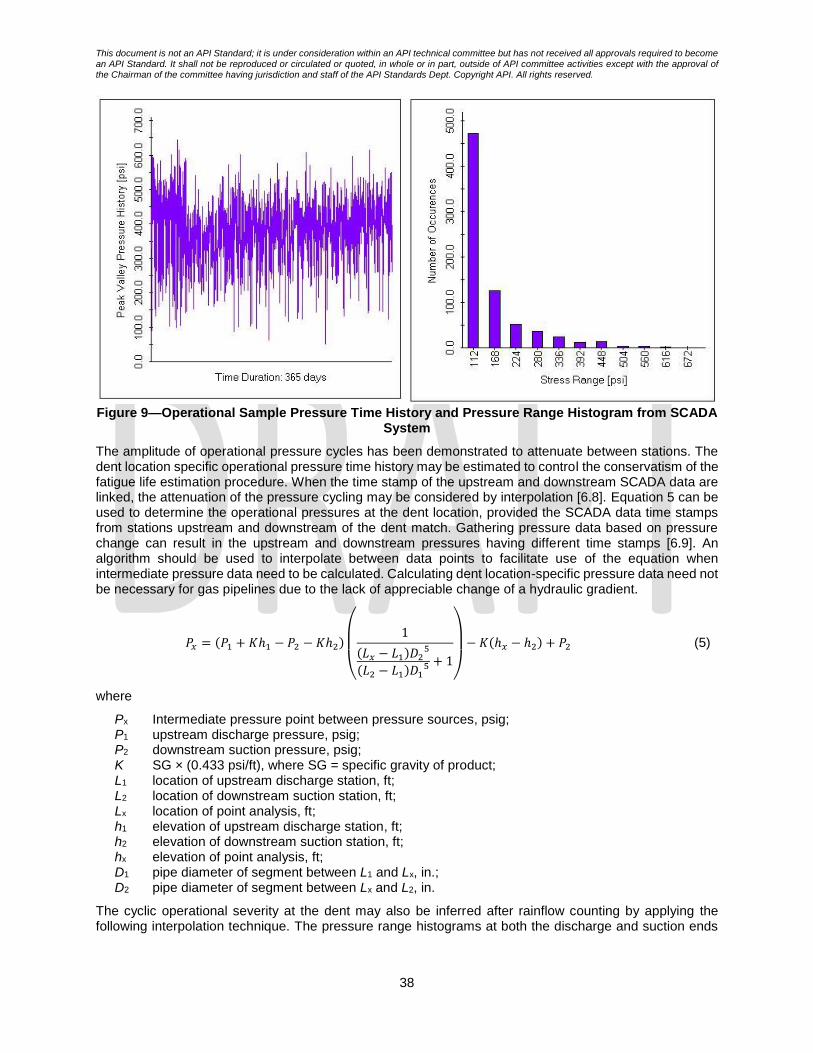
This document is not an API Standard; it is under consideration within an API technical committee but has not received all approvals required to become an API Standard. It shall not be reproduced or circulated or quoted, in whole or in part, outside of API committee activities except with the approval of the Chairman of the committee having jurisdiction and staff of the API Standards Dept. Copyright API. All rights reserved.
38
Figure 9—Operational Sample Pressure Time History and Pressure Range Histogram from SCADA
System
The amplitude of operational pressure cycles has been demonstrated to attenuate between stations. The dent location specific operational pressure time history may be estimated to control the conservatism of the fatigue life estimation procedure. When the time stamp of the upstream and downstream SCADA data are linked, the attenuation of the pressure cycling may be considered by interpolation [6.8]. Equation 5 can be used to determine the operational pressures at the dent location, provided the SCADA data time stamps from stations upstream and downstream of the dent match. Gathering pressure data based on pressure change can result in the upstream and downstream pressures having different time stamps [6.9]. An algorithm should be used to interpolate between data points to facilitate use of the equation when intermediate pressure data need to be calculated. Calculating dent location-specific pressure data need not be necessary for gas pipelines due to the lack of appreciable change of a hydraulic gradient.
𝑃𝑥 = (𝑃1 + 𝐾ℎ1 − 𝑃2 − 𝐾ℎ2)
(
1
(𝐿𝑥 − 𝐿1)𝐷25
(𝐿2 − 𝐿1)𝐷15 + 1
)
− 𝐾(ℎ𝑥 − ℎ2) + 𝑃2 (5)
where
Px Intermediate pressure point between pressure sources, psig; P1 upstream discharge pressure, psig; P2 downstream suction pressure, psig; K SG × (0.433 psi/ft), where SG = specific gravity of product; L1 location of upstream discharge station, ft; L2 location of downstream suction station, ft; Lx location of point analysis, ft; h1 elevation of upstream discharge station, ft; h2 elevation of downstream suction station, ft; hx elevation of point analysis, ft; D1 pipe diameter of segment between L1 and Lx, in.; D2 pipe diameter of segment between Lx and L2, in.
The cyclic operational severity at the dent may also be inferred after rainflow counting by applying the following interpolation technique. The pressure range histograms at both the discharge and suction ends

This document is not an API Standard; it is under consideration within an API technical committee but has not received all approvals required to become an API Standard. It shall not be reproduced or circulated or quoted, in whole or in part, outside of API committee activities except with the approval of the Chairman of the committee having jurisdiction and staff of the API Standards Dept. Copyright API. All rights reserved.
39
of a pipeline segment should be determined (using an established cycle counting method) using the same pressure range bin size (e.g., ΔP = 10kPa).
Once the pressure range histograms have been determined, the pressure range histogram at the location of interest can be estimated by applying Equation 6, to each of the bins in the histogram, i.e. the number of
cycles (𝑁𝐼𝑗) for a given pressure range (ΔPj), at an intermediate location of interest, is calculated using the
following equation: [6.6].
( )j
S
j
D
d
d
j
D
j
I NdNcabNN i
s
−
−=
` (6)
Where
𝑁𝐼𝑗 number of cycles (at pressure range ΔPj ) at intermediate location
𝑁𝐷𝑗 number of cycles (at pressure range ΔPj ) at discharge end
𝑁𝑆𝑗 number of cycles (at pressure range ΔPj ) at suction end
dI distance between discharge and intermediate location dS distance between discharge and suction (i.e. total pipeline segment length)
a, b, c and d constants depending on the product viscosity as defined in Table 4
Table 4—Cyclic Operational Pressure Range Interpolation Model Constants
Product Viscosity a b c d
≤ 100 cts 1.048 0.858 0.993 0.81
> 100 cts 1.150 0.750 1.200 1.600
The rate of fatigue damage accumulation or crack growth is related to the shape of the dent and the amplitude and frequency of pressure cycles. Dent features deform as the pipeline internal pressure changes. The rate of change of local stress (or strain) at some locations within the dent is nonlinear with the internal pressure. This nonlinearity in stress response is due to the structural and material nonlinearity of the dent deformation process. To fully consider the nonlinearity of the dent fatigue life damage accumulation process the rainflow counting process should consider both the pressure range and mean pressure of each loading cycle. For screening purposes, it may be useful to consider simply the pressure range cyclic pressure severity as shown in Figure 10.

This document is not an API Standard; it is under consideration within an API technical committee but has not received all approvals required to become an API Standard. It shall not be reproduced or circulated or quoted, in whole or in part, outside of API committee activities except with the approval of the Chairman of the committee having jurisdiction and staff of the API Standards Dept. Copyright API. All rights reserved.
40
Figure 10—Range-Mean Operational Pressure Histogram
6.6.4 Spectrum Severity Indictor (SSI)
Due to the complex, variable amplitude nature of an operating pressure time history, it is difficult to quantify the cyclic fatigue severity associated with any given time history, even after developing the pressure range histogram through rainflow counting. The Spectrum Severity Indicator (SSI) is a parameter that quantifies the cyclic fatigue severity associated with a given pressure time history [6.10].
As illustrated in Figure 11, the SSI is the number of cycles of a characteristic stress (or pressure range) that results in the same fatigue damage (i.e. crack growth) as the actual pressure time history. Although any characteristic stress range can be used as the basis for the SSI, the SSI is based on the hoop stress range of 90 MPa (13 ksi). This value represents 25 % of the yield strength of a Grade 359 (i.e. X52) steel, where a Grade 359 steel represents a common grade of steel used in the pipeline industry, and a range of 25 % represents a common operational pressure range that would be experienced by an operating pipeline.
The SSI is presented on an annual basis, regardless of the duration of the actual pressure time history. For time histories that are for a duration that is shorter or longer than one year, the damage accumulated over the entire time history is scaled to represent one year of operation.
Since the SSI calculation accounts for the cyclic pressure in a manner consistent with a fatigue life calculation, calculated fatigue lives are inversely linearly related to the SSI. If the SSI for a given pipeline operation decreases by a factor of two the estimated fatigue life for the pipeline increases by a factor of two. This can be useful when assessing the effect of various SSIs on the fatigue life of a dent or other pipeline features.

This document is not an API Standard; it is under consideration within an API technical committee but has not received all approvals required to become an API Standard. It shall not be reproduced or circulated or quoted, in whole or in part, outside of API committee activities except with the approval of the Chairman of the committee having jurisdiction and staff of the API Standards Dept. Copyright API. All rights reserved.
41
Figure 11—Spectrum Severity Indicator Description
6.7 Material Properties
The pipe material property data required is dependent on the assessment being completed. Pipe material strength, toughness, ductility and fatigue crack growth rate properties are considered in this recommended practice.
6.7.1 Material Strength
Material strength may be characterized based upon mill test reported or specific material testing results defining yield strength and ultimate strength. Dent finite element modelling fitness-for-service assessment procedures will employ pipe material full stress strain curves. If actual test data is not available, the user may consider the specified minimum properties (e.g., specified minimum yield strength and specified minimum ultimate tensile strength) associated with the pipe grade.
If measured or pipe grade (specified minimum strength properties) are not known, the operator shall:
- consider the same material properties that are the basis for the current MAOP; - Use strength data from pipe with similar vintage and manufacturing process; - use industry recommend values for unknown materials (e.g., INGAA [6.10], GPAC [6.13]); or - verify material properties through tensile testing or non-destructive (in-ditch) material
characterization opportunistically
6.7.2 Material Toughness
In the presented fitness-for-service assessment procedures, material toughness is characterized using Charpy Vee Notch (CVN) impact energy and fracture toughness (e.g., CTOD, K). The toughness material property shall be considered at the operating temperature. The material toughness data shall be drawn from mill testing of the pipe material or from mill test reports. If test data or mill test reports are not available, material specific minimum specified toughness values may be used.
If material toughness is not known from testing, specification or records are not available, the operator shall:
- Use toughness data from similar vintage pipe until properties are obtained through opportunistic for testing;
- Verify Charpy energy values based upon the material testing or non-destructive (in-ditch) material characterization
- use industry recommend values for unknown materials (e.g., INGAA [6.10], GPAC [6.14]); or
This document is not an API Standard; it is under consideration within an API technical committee but has not received all approvals required to become an API Standard. It shall not be reproduced or circulated or quoted, in whole or in part, outside of API committee activities except with the approval of the Chairman of the committee having jurisdiction and staff of the API Standards Dept. Copyright API. All rights reserved.
42
- Use other appropriate values based on technology or technical publications that an operator demonstrates can provide conservative Charpy energy values of the crack-related conditions of the line pipe.
The low toughness value recommended for uncharacterized materials, can be problematic in the application of fitness-for-service assessment techniques.
6.7.3 Fatigue Crack Growth Rate
Standard material crack growth rate date presented in industry codes of practice such as API 579 [6.5] may be used in dent fatigue life assessment. Testing may be used to develop material specific fatigue crack growth rate data [6.11].
References [6.1] Pipeline Research Council International, “Fatigue Life Assessment of Dents with and without
Interacting Features”, MD 4-9 PRCI Final Report prepared by BMT, Catalog No. PR-214-114500-R01, November 2018.
[6.2] Full-Scale Demonstration of the Interaction of Dents with Welds and Localized Corrosion Defects, PRCI Project MD-4-2 (PR-214-073510)
[6.3] Full-scale testing of Interactive Features for Improved Models” DOT Final Report DTPH56-14-H-0002, 2017.
[6.4] Alexander, C.R. and Kiefner, J.F. “Effects of Smooth and Rock dents on Liquid petroleum Pipelines” API 1156, First Edition 1997
[6.5] American Petroleum Institute, “Fitness-For-Service”, API Recommended Practice 579, January 1st ed.; 2000.
[6.6] American Petroleum Institute, “Managing System Integrity for Hazardous Liquid Pipelines”, API 1160 -2019,
[6.7] American Society for Testing and Materials, Standard Practices for Cycle Counting in Fatigue Analysis, ASTM E1049-85 (Re-approved 1997).
[6.8] Michael Baker Jr., Inc., “Low Frequency ERW and Lap Welded Longitudinal Seam Evaluation”, US DOT TT 05 Report, Integrity Management Program Delivery Order DTRS56-02-D-70036
[6.9] Semiga,V, Dinovitzer,A, Tiku,S, Vignal,G, “Liquid Pipeline Location Specific Cyclic Pressure Determination”, International Pipeline Conference, Paper IPC2018-78717, 2018
[6.10] BMT Fleet Technology, “Fatigue Considerations for Natural Gas Transmission Pipelines”, Report Prepared for Interstate Natural Gas Association of America (INGAA)
[6.11] Pipeline Research Council International, “ERW Fatigue Life Integrity Management Improvement”, PRCI IM-3-2 Report prepared by BMT 2019.
[6.12] American Society of Mechanical Engineering, “Gas Transmission and Distribution Piping System”, ASME B31.8-2018
[6.13] PHMSA, Safety of Gas Transmission and Gathering Pipelines at 185, GPAC Meeting (Mar. 26-28, 2018), https://primis.phmsa.dot.gov/meetings/FilGet.mtg?fil=938.
[6.14] GPAC Meeting Final Voting Slides at 6 (Mar. 26-28, 2018), https://primis.phmsa.dot.gov/meetings/FilGet.mtg?fil=966
7 Dent Feature Screening
Not all dent features are injurious to pipeline integrity. The significance of a dent feature is evaluated relative to the maximum operating pressure and expected design life or expected remaining pipeline service life of the pipeline for fitness-for-service.
This section provides screening techniques which are conservative fitness-for-service assessment for mechanical damage features to quickly identify those features which are non-injurious. The screening techniques are presented in increasing orders of complexity and decreasing levels of conservatism. The techniques that are easiest to apply and are the most conservative are presented first.
Beyond the screening techniques provided in this section, the operator should consider the potential for deep dents interfering with internal inspection or cleaning.

This document is not an API Standard; it is under consideration within an API technical committee but has not received all approvals required to become an API Standard. It shall not be reproduced or circulated or quoted, in whole or in part, outside of API committee activities except with the approval of the Chairman of the committee having jurisdiction and staff of the API Standards Dept. Copyright API. All rights reserved.
43
The approaches presented in this section are available techniques; alternate engineering analysis and testing may be used to complete feature ranking or screening.
Those features that are deemed non-injurious based using the screening fitness-for-service approaches are fit for service and do not need remediation or further assessment using the detailed fitness for service assessment approached in Section 8.
7.1 Qualitative Risk Screening
Semi-quantitative screening processes such as that provided in Figure 11 [7.4] may be considered for mechanical damage features to preclude failure due to pressure increase induced. The approach presented considers dent severity, corrosion, welds and cracking. Fatigue is not considered explicitly in this example process and may be added. This type of qualitative dent screening system may be a useful element of an integrity management plan that considers screening and assessment tools presented in this RP.

This document is not an API Standard; it is under consideration within an API technical committee but has not received all approvals required to become an API Standard. It shall not be reproduced or circulated or quoted, in whole or in part, outside of API committee activities except with the approval of the Chairman of the committee having jurisdiction and staff of the API Standards Dept. Copyright API. All rights reserved.
44
Figure 11: Example Semi-Quantitative Mechanical Damage Pressure Increase Induced Damage Limit Screening Process

This document is not an API Standard; it is under consideration within an API technical committee but has not received all approvals required to become an API Standard. It shall not be reproduced or circulated or quoted, in whole or in part, outside of API committee activities except with the approval of the Chairman of the committee having jurisdiction and staff of the API Standards Dept. Copyright API. All rights reserved.
45
Figure 12: Example Semi-Quantitative Mechanical Damage Pressure Increase Induced Damage Limit Screening Process (Continued….)

This document is not an API Standard; it is under consideration within an API technical committee but has not received all approvals required to become an API Standard. It shall not be reproduced or circulated or quoted, in whole or in part, outside of API committee activities except with the approval of the Chairman of the committee having jurisdiction and staff of the API Standards Dept. Copyright API. All rights reserved.
46
7.2 Indentation Formation Strain
The shape of the dent may be used to infer the dent formation strain and consider the potential for forming a crack during indentation.
Strain in dents may be estimated using data from ILI tools or from direct measurement of dent deformation contour. Direct measurement techniques may consist of any method capable of describing the depth and shape terms needed to estimate strain. The strain estimating techniques may differ depending on the type of data available. Interpolation or other mathematical techniques may be used to develop surface contour information from ILI or direct measurement data. Although a method for estimating strain [7.5] is described herein, it is not intended to preclude the use of other strain estimating techniques such as the DFDI technique described in Section 8.1.3.1 [7.6].
According to the ASME B31.8 Appendix R (2018) [7.5] the estimation of the maximum strain in a dent is performed by first evaluating separately the following three strain components.
- Bending strain in circumferential direction - At the apex of a dent, the term ε1 is negative representing compression at the outside pipe surface and positive representing tension on the inside pipe surface. This can be calculated using Equation 7:
휀1 =𝑡
2(1
𝑅0−1
𝑅1)
(7)
- Bending strain in longitudinal direction - At the apex of a dent, the term ε2 is negative representing compression at the outside pipe surface and positive representing tension on the inside pipe surface. This can be calculated using Equation 8:
휀2 = −𝑡
2(1
𝑅2)
(8)
- Membrane strain in longitudinal direction can be determined using Equation 9
휀3 =1
2(𝑑
𝐿)2
(9)
In these equations, R0 is the radius of curvature of undeformed pipe surface, which is half of the nominal outside diameter of the pipe and t, d, L correspond, respectively, to the wall thickness, dent depth and dent length in longitudinal direction. The R1, R2 are the external surface radii of curvature and are measured respectively, in the transverse and longitudinal planes through the dent respectively. The value of R1 is positive when a dent partially flattens the pipe, in such cases, the curvature of the pipe surface in the transverse plane is in the same direction as the original surface radius of curvature. Otherwise, if the pipe curvature at the dent has reversed (e.g., is concave), value of R1 is negative. The value of R2 is generally negative.
ASME B 31.8 assumes that the membrane strain in the circumferential direction is negligible. All the strain components are combined according to the following equation with positive and negative values for ε1 and ε2 carried through Equation 10 to define the combined strain on the inside and outside surfaces of the pipe.
휀 =2
√3√휀1
2 − 휀1(휀2 + 휀3) + (휀2 + 휀3)2
(10)
The dent is considered at risk of containing a crack when when the larger of the inside or outside surface strain value is greater than:
- 40 % of average elongation from MTRs,
- 50 % of specified minimum elongation (EL) defined in the pipe specification or purchase order, or
- 6 % strain where MTR’s are unavailable, and the pipe specification is unknown.
7.3 Pressure Increase Induced Damage Screening
Plain dent features regardless of shape with depths up to 10 % of the pipe diameter, without coincident metal loss, weld or crack features have been shown in testing to have the same failure pressure as plain linepipe [7.1, 7.2, 7.3]. The pressure increase induced damage limit of plain dent features does not need to

This document is not an API Standard; it is under consideration within an API technical committee but has not received all approvals required to become an API Standard. It shall not be reproduced or circulated or quoted, in whole or in part, outside of API committee activities except with the approval of the Chairman of the committee having jurisdiction and staff of the API Standards Dept. Copyright API. All rights reserved.
47
be considered. The pressure increase induced damage limit of the pipeline segment in the absence of the dent feature should be considered to support integrity assessment and management.
Dents that contain corroded areas having a depth greater than 10 %, up to and including 40 %, of the nominal wall thickness of the pipe and a depth and length that exceed the maximum allowable longitudinal extent determined as specified in ASME B31G shall be considered defects [7.12].
The potential for cracking as a result of indentation should be considered (see Section 7.2) in characterizing a plain dent. A dent with a crack or suspected crack is not considered a plain dent.
7.4 Fatigue Life Dent Screening
The fatigue life of a plain dent is primarily a function of the dent shape, restraint condition, operational pressure time history and the pipe geometry (i.e. diameter and wall thickness). All operational pressure cycles contribute to fatigue damage or fatigue crack growth accumulation and the damage accumulation (or fatigue crack growth) per cycle is related to magnitude of the pressure cycle. It is possible that the rate of fatigue damage accumulation (or fatigue crack growth) is low enough to result in a dent feature with a fatigue life that exceeds the design life of the pipeline.
The goal of a fatigue life screening process is to identify combinations of dent features, operational pressure time histories and pipe geometry that exceed the pipeline design life. Screening processes develop conservative fatigue life estimates by considering upper bound behaviours associated with the dent shape, restraint condition, operational pressure time history and/or the pipe geometry and as such may be presented without reference to one or more of these factors.
The approaches presented the section that follow were developed with decreasing levels of conservatism and increasing data requirements. If any one of the approaches presented in the sections that follow demonstrate that the dent feature has a longer fatigue life that the pipeline design life, the dent feature is considered not susceptible to fatigue over the design life period. The screening results should be periodically reviewed to ensure that the assumed operational severity of the pipeline segment remains a valid assumption.
The design life of the pipeline segment shall be defined by the pipeline operator considering the expected future use of the pipeline system and the risk associated with failure.
7.4.1 Operational Severity Fatigue Life Screening
By considering a range of dent shapes and pipe geometries a screening approach has been developed to consider the dent cyclic loading severity for restrained and unrestrained dents [7.7]. The spectrum severity of a pipeline operational pressure time history is defined using the spectrum severity indicator (SSI) [7.8] as outlined in Section 6.6.4. The restraint condition [7.9] of dent is evaluated based upon its shape as defined in Section 6.4.
The minimum expected fatigue life of restrained and unrestrained dent features is defined in Tables 5 and 6, respectively. In using the tables, columns and rows associated with dent depths (d) and spectrum severity factors (SSI) greater than or equal to the dent feature depth and operational severity shall be used. A dent feature’s fatigue susceptibility is best related to the shape of the dent rather than just the depth. The results presented in this section are based upon lower bound fatigue lives for a range of dent shapes formed in a range of pipe geometries grouped by maximum dent depth. In this grouping the range of variation in lives is greatest for restrained dents with a few severe shapes having lower lives resulting in lower lives when compared to unrestrained dents of the same depth. This is contrary to the long held observation that unrestrained dents have shorter lives than similarly shaped restrained dents; this result is due to the lower bound grouping for fatigue lives used in developing this tool and the range of variability of response of restrained and unrestrained dents.
A fatigue life reduction factor may be applied to the screening tool estimated fatigue life to consider the impact of weld or corrosion interaction with the dent feature, as outlined in Sections 6.5.1 and 6.5.2.
Table 5—Dent Feature Fatigue Life Spectrum Severity Criteria – Restrained Dents
Dent Depth, d [% OD] d < 1.0 d < 1.5 d < 2.0 d < 3.0 d < 4.0 d < 5.0 d < 7.0
SSI (Annual 13ksi hoop Fatigue Life (Years)

This document is not an API Standard; it is under consideration within an API technical committee but has not received all approvals required to become an API Standard. It shall not be reproduced or circulated or quoted, in whole or in part, outside of API committee activities except with the approval of the Chairman of the committee having jurisdiction and staff of the API Standards Dept. Copyright API. All rights reserved.
48
stress cycles)
10 5,692 5,276 4,899 3,964 3,705 3,252 3,053
30 1,897 1,759 1,633 1,321 1,235 1,084 1,018
50 1,138 1,055 980 793 741 650 611
70 813 754 700 566 529 465 436
90 632 586 544 440 412 361 339
110 517 480 445 360 337 296 278
130 438 406 377 305 285 250 235
150 379 352 327 264 247 217 204
200 285 264 245 198 185 163 153
300 190 176 163 132 124 108 102
400 142 132 122 99 93 81 76
500 114 106 98 79 74 65 61
750 76 70 65 53 49 43 41
1000 57 53 49 40 37 33 31
1250 46 42 39 32 30 26 24
1500 38 35 33 26 25 22 20
1750 33 30 28 23 21 19 17
2000 28 26 24 20 19 16 15
Table 6—Dent Feature Fatigue Life Spectrum Severity Criteria – Unrestrained Dents
Dent Depth, d [% OD] d < 1.0 d < 1.5 d < 2.0 d < 3.0 d < 4.0 d < 5.0
SSI (Annual 13ksi Hoop stress cycles)
Fatigue Life (Years)
10 17,155 8981 7237 6403 6153 5917
30 5718 2994 2412 2134 2051 1972
50 3431 1796 1447 1281 1231 1183
70 2451 1283 1034 915 879 845
90 1906 998 804 711 684 657
110 1560 816 658 582 559 538
130 1320 691 557 493 473 455
150 1144 599 482 427 410 394
200 858 449 362 320 308 296
300 572 299 241 213 205 197
400 429 225 181 160 154 148
500 343 180 145 128 123 118
750 229 120 96 85 82 79
1000 172 90 72 64 62 59
1250 137 72 58 51 49 47
1500 114 60 48 43 41 39
1750 98 51 41 37 35 34
2000 86 45 36 32 31 30
7.4.2 Shallow Restrained and Unrestrained Dent Spectrum Severity Indicator Fatigue Life Screening
A screening approach has been developed to consider the dent cyclic loading severity for shallow restrained and all unrestrained dents [7.9, 7.10]. The spectrum severity of a pipeline operational pressure time history is defined using the spectrum severity indicator (SSI) as outlined in Section 6.6.4. The restraint condition of dent is evaluated based upon its shape as defined in Section 6.4.
Shallow restrained and unrestrained dents may be demonstrated to be non-injurious from a fatigue viewpoint depending on the pipe geometry (D/t) and operational spectrum severity indicator (SSI) at the dent feature. Dents are defined as shallow under the following conditions:
- Dent depth < 4% of pipe OD [for OD ≤ 12.75 in. (324 mm)]

This document is not an API Standard; it is under consideration within an API technical committee but has not received all approvals required to become an API Standard. It shall not be reproduced or circulated or quoted, in whole or in part, outside of API committee activities except with the approval of the Chairman of the committee having jurisdiction and staff of the API Standards Dept. Copyright API. All rights reserved.
49
- Dent depth < 2.5% of pipe OD [for OD > 12.75 in. (324 mm)]
For shallow dents the lower bound fatigue life in years is calculated with Equation 11:
𝐹𝑎𝑡𝑖𝑔𝑢𝑒 𝐿𝑖𝑓𝑒 > 1012.6007−3 𝐿𝑜𝑔10(13 𝐾𝑀
𝑀𝑎𝑥)
𝑆𝑆𝐼
(11)
Where:
SSI is the spectrum severity factor
𝐾𝑀𝑀𝑎𝑥 is the dent feature maximum stress magnification factor, and
For Unrestrained Dents
- that have experienced a pressure greater than 20% PSMYS in service
𝐾𝑀𝑀𝑎𝑥 = 7.5 [1 - exp(-0.065 OD / t)]
- that have not experienced a pressure greater than 20% PSMYS in service
𝐾𝑀𝑀𝑎𝑥 = 9.4 [1 – exp(-0.045 OD / t)]
For Restrained Dents
𝐾𝑀𝑀𝑎𝑥 = 0.1183 (OD/t) -1.146
NOTE This screening tool was developed for a range of pipe sizes with OD/t ranging from 20 to 130.
If the calculated lower bound fatigue life is greater than the pipeline desired operating life the dent feature is considered to not be susceptible to fatigue over the desired service life. If the calculated fatigue life is less than the desired service life, more detailed fatigue life calculations as defined later in this section or in Section 8 may be applied.
A fatigue life reduction factor may be applied to the screening tool estimated fatigue life to consider the impact of weld or corrosion interaction with the dent feature, as outlined in Sections 6.5.1 and 6.5.2.
7.4.3 Shallow Restrained Dent and Unrestrained Dent Operational Pressure Spectrum Fatigue Life Screening
By considering a range of dent shapes and pipe geometries, a screening approach has been developed to consider the dent cyclic loading severity for shallow restrained and all unrestrained dents. The operational pressure spectrum severity of a pipeline operational pressure time history is defined using a histogram of pressure range magnitudes from the rainflow counting process [7.11], as outlined in Section 6.6.3.1. The restraint condition of dent is evaluated based upon its shape as defined in Section 6.4.
Shallow restrained and all unrestrained dents may be demonstrated to be non-injurious from a fatigue viewpoint depending on the pipe geometry (D/t) and operational spectrum severity histogram at the dent feature. Restrained dents are defined as shallow under the following conditions:
- Dent depth < 4% of pipe OD [for OD ≤ 12.75 in (324 mm)]
- Dent depth < 2.5% of pipe OD [for OD > 12.75 in (324 mm)]
For shallow restrained dents and all unrestrained dents the following screening process may be applied to calculate a lower bound fatigue life in years:
1) Carry out Rainflow analysis for the pressure time history and sort data into appropriate pressure range bin sizes and corresponding number of cycles;
2) Convert pressure range bin sizes into %ΔPSMYS;
3) Base on pipe geometry calculate 𝐾𝑀𝑀𝑎𝑥, using Equation 11 for shallow restrained dents and
Equation 11 or 15 or 16 for unrestrained dents (Section 7.4.3.1), for each of the pressure range bins (%ΔPSMYS);
4) For each pressure range bin, multiply 𝐾𝑀𝑀𝑎𝑥 by the pressure range magnitude (%ΔPSMYS) of the
histogram to obtain the dent critical stress ranges;

This document is not an API Standard; it is under consideration within an API technical committee but has not received all approvals required to become an API Standard. It shall not be reproduced or circulated or quoted, in whole or in part, outside of API committee activities except with the approval of the Chairman of the committee having jurisdiction and staff of the API Standards Dept. Copyright API. All rights reserved.
50
5) Calculate fatigue damage for each pressure range bin, using Equation 12;
log𝑁𝑖 = log𝐶 –𝑚 ∗ log(Δσ𝑖)
𝐷𝑖 = 𝑛𝑖 𝑁𝑖⁄ (12)
6) Use Miner’s linear cumulative damage summation to calculate the total fatigue damage accumulated in all the pressure range bins. This is shown in Equation 13:
𝐷𝑡𝑜𝑡𝑎𝑙 =∑𝐷𝑘
𝑀
𝑘=1
(13)
7) Calculate remaining fatigue damage by subtracting total fatigue damage from 1; and
8) Calculate fatigue life based on the remaining damage with Equation 14:
𝑁𝑅 = 1 𝐷𝑡𝑜𝑡𝑎𝑙⁄ (14)
If the calculated lower bound fatigue life is greater than the pipeline segment design life or pipeline remaining expected operating life the dent feature is considered to not be susceptible to fatigue over the desired service life. If the calculated fatigue life is less than the desired service life, more detailed and less conservative fatigue life calculations as defined in Section 8 may be applied.
A fatigue life reduction factor may be applied to the screening tool estimated fatigue life to consider the impact of weld or corrosion interaction with the dent feature, as outlined in Sections 6.5.1 and 6.5.2.
7.4.3.1 Unrestrained Dent Advanced Screening Stress Magnification Factors
Maximum stress magnification factor, 𝐾𝑀𝑀𝑎𝑥, for unrestrained dents corresponding to each pressure range
condition for individual pipe geometry (OD/t) was extracted and plotted against the pressure range. The correlation follows a quadratic function as shown in Equation 15:
𝐾𝑀𝑀𝑎𝑥 = 𝑎 ∗ 𝛥𝑃2 + 𝑏 ∗ 𝛥𝑃 + 𝑐 (15)
where a, b, and c are coefficients of the function in Equation 15 and are listed in Table 7.
Table 7—Quadratic Function Constants for Equation (7.9) for the Pipe Geometries
OD/t [in/in] Constant (a) Constant (b) Constant (c)
24 (4.5/0.188) -2.2600E-05 -5.3239E-02 6.6658
35 (6.625/0.188) 9.5242E-04 -1.5553E-01 8.6799
40 (8.625/0.218) 2.2700E-05 -7.2248E-02 7.7703
41 (12.75/0.312) -9.2500E-05 -5.1883E-02 6.8884
57 (10.75/0.188) 9.7536E-04 -1.5842E-01 8.2795
58 (18/0.312) 7.3803E-04 -1.4489E-01 9.4614
71 (20/0.281) 1.4251E-03 -2.0873E-01 10.7244
73 (16/0.218) 5.7780E-04 -1.2481E-01 8.8566
85 (24/0.281) 1.2860E-03 -1.9800E-01 10.5981
96 (24/0.25) 1.2724E-03 -1.8877E-01 10.2145
100 (42/0.42) 6.7473E-04 -1.4078E-01 9.4286
114 (32/0.281) 7.4031E-04 -1.4688E-01 9.4987
120 (30/0.25) 1.1607E-03 -1.7704E-01 9.9170
128 (36/0.281) 8.0752E-04 -1.5251E-01 9.5362
A simplified regression equation, Equation 16, was developed to combine all the correlations for individual OD/t’s provided for in Equation 15. This equation can be used instead of multiple correlations for individual OD/t.

This document is not an API Standard; it is under consideration within an API technical committee but has not received all approvals required to become an API Standard. It shall not be reproduced or circulated or quoted, in whole or in part, outside of API committee activities except with the approval of the Chairman of the committee having jurisdiction and staff of the API Standards Dept. Copyright API. All rights reserved.
51
𝐾𝑀𝑀𝑎𝑥(𝑥, 𝑦) = 𝑎00 + 𝑎10𝑥 + 𝑎01𝑦 + 𝑎20𝑥
2 + 𝑎11𝑥𝑦 + 𝑎02𝑦2 + 𝑎30𝑥
3 + 𝑎21𝑥2𝑦 + 𝑎12𝑥𝑦
2 (16)
where 𝑥 refers to the pressure range, Δ𝑃/∆𝑃𝑆𝑀𝑌𝑆 and 𝑦 refers to the pipe 𝑂𝐷/𝑡. Equations 15 and 16 are
valid for pipe geometries ranging between 24 ≤ 𝑂𝐷 𝑡⁄ ≤ 128.
The coefficients 𝑎𝑖𝑗 for the regression Equation 16 are provided in Table 8.
Table 8—Constants 𝒂𝒊𝒋 for Regression Equation (16)
𝒂𝟎𝟎 𝒂𝟏𝟎 𝒂𝟎𝟏 𝒂𝟐𝟎 𝒂𝟏𝟏 𝒂𝟎𝟐 𝒂𝟑𝟎 𝒂𝟐𝟏 𝒂𝟏𝟐 6.61847 -12.26386 0.06748 15.58507 -0.12358 -0.00032 -8.58441 0.03803 0.00047
7.5 Finite Element Modelling Screening
Finite element modelling of a dent may be used as a screening tool. In some instances, a rapid assessment may be completed by creating a finite element model of the dented pipeline shape. These models do not capture the residual stresses and non-linear behaviour of the dent developed by the dent formation process; they can prove useful in rapidly approximating the dent response and fatigue life. Dent stress concentration factor (SCF) approaches make use of the 3D dent shape captured by ILI tools or in-field measurements (typically laser scans). Individual, unique elastic finite element models are constructed for each dent to calculate the maximum principal stresses in the dent, which may then be used to calculate the elastic stress concentration factors (SCFs) for each dent [7.13, 7.14]. The SCF is defined as the ratio of the peak stresses from the model to the nominal hoop stress used in the finite element models. The nominal pressure applied to the dent should be selected such that is within the expected operating pressure range of the dents.
The SCF analysis may be combined with pressure history data (discretized using a rainflow counting algorithm) and appropriate S-N curves to rank the remaining fatigue life of a dent. This approach is most applicable to un-restrained features that have experienced shake down to elastic action. The SCF has been used to indicate dent restraint condition [7.14]. The SCF approach is not limited by dent shape or complexity if the measurement technique can accurately capture the shape of the dent. The SCF approach may be extended to restrained dents. Care should be taken when evaluating the conservatism of these results.
References [7.1] Full-Scale Demonstration of the Interaction of Dents with Welds and Localized Corrosion Defects,
PRCI Project MD-4-2 (PR-214-073510) [7.2] Full-scale testing of Interactive Features for Improved Models” DOT Final Report DTPH56-14-H-0002,
2017. [7.3] Alexander, C.R. and Kiefner, J.F. “Effects of Smooth and Rock dents on Liquid petroleum Pipelines”
API 1156, First Edition 1997 [7.4] Zhang,F, Rosenfeld,M, “Technical Background Of A Simplified Process For Conducting ECA Of
Indicated Pipeline Indentations With Metal Loss”, Pipeline Pigging & Integrity Management Conference, Feb 2019
[7.5] American Society of Mechanical Engineering, “Gas Transmission and Distribution Piping System”, ASME B31.8-2018
[7.6] Arumugam,U, Gao,M, Krishnamurthy,R, Wang,R, Kania,R, “Study of a Plastic Strain Limit Damage Criterion for Pipeline Mechanical Damage Using FEA and Full-Scale Denting Test”, International Pipeline Conference, IPC2016-64548
[7.7] BMT Fleet Technology, “Fatigue Considerations for Natural Gas Transmission Pipelines”, Report Prepared for Interstate Natural Gas Association of America (INGAA)
[7.8] Semiga,V, Dinovitzer,A, Tiku,S, Vignal,G, “Liquid Pipeline Location Specific Cyclic Pressure Determination”, International Pipeline Conference, Paper IPC2018-78717, 2018
[7.9] Pipeline Research Council International, “Fatigue Life Assessment of Dents with and without Interacting Features”, MD 4-9 PRCI Final Report prepared by BMT, Catalog No. PR-214-114500-R01, November 2018.
[7.10] Canadian Energy Pipeline Association, “Management of Shallow Retrained Dents”, CEPA Report prepared by BMT, 2018.
[7.11] American Society for Testing and Materials, Standard Practices for Cycle Counting in Fatigue Analysis, ASTM E1049-85 (Re-approved 1997).

This document is not an API Standard; it is under consideration within an API technical committee but has not received all approvals required to become an API Standard. It shall not be reproduced or circulated or quoted, in whole or in part, outside of API committee activities except with the approval of the Chairman of the committee having jurisdiction and staff of the API Standards Dept. Copyright API. All rights reserved.
52
[7.12] Canadian Standards Association, “Oil and Gas Pipeline Systems”, CSA Z662-15. [7.13] Dotson,R, Ginten,M, Alexander,C, Bedoya,J, Schroeer,K, “ Combining High Resolution In-Line
Geometry Tools and Finite Element Analysis to Improve Dent Assessments”, Paper No. PPIM-ILI2-16, Pipeline Pigging & Integrity Management Conference, Houston, Texas, February 10-13, 2014.
[7.14] Dotson,R, Holliday,C, Torres,L, Hagan,D, “An Authoritative Comparison of Remaining Life Assessments for Pipeline Dents, Proceedings of IPC 2018 (Paper No. IPC2018-78247), 12th International Pipeline Conference, September 24 – 28, 2018, Calgary, Alberta, Canada.

This document is not an API Standard; it is under consideration within an API technical committee but has not received all approvals required to become an API Standard. It shall not be reproduced or circulated or quoted, in whole or in part, outside of API committee activities except with the approval of the Chairman of the committee having jurisdiction and staff of the API Standards Dept. Copyright API. All rights reserved.
53
8 Detailed Fitness-For-Service Assessment Approaches
Integrity assessment of dent features may be completed at various levels of detail with higher detail assessments incorporating lower levels of conservatism. The most involved or complex approaches that are the most generally applicable employ detailed non-linear finite element analysis (e.g., Level 3). Procedures other than those presented in this Section of the RP may be considered in the assessment of fitness-for-service. Users should develop an understanding of the assessment procedures they employ to ensure their engineering basis and validity regarding the asset being operated.
The fitness-for-service of dent features that were not evaluated as non-injurious based on screening tools (Section 7) or those of interest are evaluated based upon the approaches in this section. Features identified as non-injurious by screening tools as considered fit-for-service.
The approaches presented in this section are available techniques; alternate engineering analysis and testing may be used to complete feature fitness-for-service assessment.
8.1 Dent Pressure Increase Induced Damage Assessment
The pressure increase induced damage limit for dents may be evaluated using both stress- and strain-based criteria. The stress-based criteria consider fracture and plastic collapse based upon failure assessment diagram (FAD) approaches. The failure assessment approaches follow techniques outlined in in BS 7910 [8.1] and API 579 [8.2] and can consider the presence of coincident features. Coincident features are treated as general wall thinning or cracks or stress concentration effects.
There are no methods for reliably predicting the pressure increase induced damage limit of a smooth dent on a weld. Research work suggests that sound ERW welds do not affect the pressure increase induced damage limit of dents [8.13]
Dents containing locations with high levels of curvature, are a concern for stress-based pressure increase induced damage limit evaluation. While the behavior of these features has been a concern, there are no published methods for predicting their behavior.
8.1.1 Dent Gouge Pressure Increase Induced Damage Assessment
The pressure increase induced damage limit of a dent containing a gouge may be estimated by considering the dent depth at zero internal pressure as defined in Equation 17 [8.3]. To implement this approach a relationship between dent depth at zero pressure and measured dent depth at operating or measurement pressure should be developed.

This document is not an API Standard; it is under consideration within an API technical committee but has not received all approvals required to become an API Standard. It shall not be reproduced or circulated or quoted, in whole or in part, outside of API committee activities except with the approval of the Chairman of the committee having jurisdiction and staff of the API Standards Dept. Copyright API. All rights reserved.
54
𝑃𝑓 = 2 𝑡 2 𝜎
𝐷 𝜋𝑐𝑜𝑠−1 (𝑒𝑥𝑝 [−𝛼 𝛽
𝛿
𝑑])
Where
𝛿 =169.5 𝜋 𝐸
𝜎2𝐴
𝜎 = 1.15 𝜎𝑦 (1 −𝑑
𝑡)
𝛼 = [𝑌1 (1 − 1.8𝐻𝑜𝐷) + 𝑌2 (5.1
𝐷 𝐻𝑜𝑡 𝐷
)]−2
𝛽 = 𝑒𝑥𝑝 (𝑙𝑛((0.738𝐶𝑉) − 1.9)
0.57)
𝑌1 = 1.12 − 0.23 (𝑑
𝑡) + 10.6 (
𝑑
𝑡)2
− 21.7 (𝑑
𝑡)3
+ 30.4 (𝑑
𝑡)4
𝑌2 = 1.12 − 1.39 (𝑑
𝑡) + 7.32 (
𝑑
𝑡)2
− 13.1 (𝑑
𝑡)3
+ 14.0 (𝑑
𝑡)4
D pipe outside diameter (mm) T pipe wall thickness (mm) σ nominal hoop stress (MPa) d gouge depth (mm) E Modulus of elasticity A fracture area of a 2/3 Charpy specimen (53.55 mm2 for a 2/3
Charpy specimen) (mm2 ) Ho Dent depth at zero internal pressure (mm) Cv Full size Charpy impact energy (J)
(17)
The zero-pressure dent depth may be estimated as 143 % of the operating pressure dent depth (pressurized depth is 0.70 of unpressurized depth), if the operating pressure is greater than or equal to 50 % of the SMYS pressure [8.2]. Otherwise the pressurized dent depth may be assumed to be equal to the unpressurized dent depth.
8.1.2 Indentation Formation Strain – ASME B31.8 Appendix R
Using the dent strain screening, as outlined in Section 7.2, a dent is considered to not be susceptible to indention process cracking when the larger of the inside or outside surface strain value is lower than:
- 40 % of average elongation from MTRs,
- 50 % of specified minimum elongation (EL) defined in the pipe specification or purchase order, or
- 6 % strain where MTR’s are unavailable, and the pipe specification is unknown.
Francini and Yoosef-Ghodsi [8.14] reviewed the current ASME B31.8 strain equations and proposed an alternative strain limit for plain dents using specified minimum elongation of the pipe steel grade. The proposed limit of the equivalent strain (εeq) in a plain dent is calculated with Equation 18:
SF
e
SF
ff
eq
(18)
where εf and ef are the true fracture strain and the specified minimum elongation to failure, respectively, and SF is the safety factor.
Francini and Yoosef-Ghodsi recommended the following criterion as an alternative to the current ASME B31.8 6 % strain limit: “If the plain dent is not associated with a weld, a dent with a calculated equivalent strain less than one-half of the specified minimum elongation for the pipe steel grade is considered benign”. Using this minimum elongation limit criterion, the alternate strain limit is 9 % to 12 % for typical line pipe steels (i.e. typical elongation to failure 18 % to 24 %).

This document is not an API Standard; it is under consideration within an API technical committee but has not received all approvals required to become an API Standard. It shall not be reproduced or circulated or quoted, in whole or in part, outside of API committee activities except with the approval of the Chairman of the committee having jurisdiction and staff of the API Standards Dept. Copyright API. All rights reserved.
55
Both the minimum specified elongation criterion and the strain limit damage (SLD) criterion are developed to assess fitness for purpose, not for failure prediction. For prediction of susceptibility to cracking, engineering critical assessment, or failure analysis, the actual material properties should be used, in particular, the true strain for failure.
8.1.3 Cracking Susceptibility During Dent Formation
If a crack forms in a dent during indentation, then the pressure increase induced damage limit for the dent feature is significantly reduced from that of a plain dent. Based on this, it is possible to consider the formation of a crack in a dent as an indicator that the dent is not fit for service and should be remediated or removed from service.
The criteria for evaluating the potential for crack formation on indentation include the Ductile Failure Damage Indicator (DFDI) [8.4], the combined MFL plus DFDI and the ASME Section VIII, Division 2 based Strain Limit Damage (SLD) approach.
8.1.3.1 Ductile Failure Damage Indicator (DFDI)
The Ductile Failure Damage Indicator (DFDI) crack formation strain model considers stress triaxiality to evaluate the strain to failure. The critical strain for a material is evaluated based upon a reference failure strain, εf, i.e., a strain limit for ductile failure, which can be expressed by stress tri-axiality, 𝜎𝑚/𝜎𝑒𝑞, and material’s critical strain, εo as shown in Equation 19:
휀𝑓 = 1.65휀𝑂 exp (−3𝜎𝑚2𝜎𝑒𝑞
)
Where:
𝜎𝑚 =1
3(𝜎1 + 𝜎2 + 𝜎3)
𝜎𝑒𝑞 =1
√2√(𝜎1 − 𝜎2)
2 + (𝜎2 − 𝜎3)2 + (𝜎3 − 𝜎1)
2
(19)
In the equation, σm is the mean stress of three principal stresses in a tri-axial stress field, σeq is the von Mise’s stress, and σ1, σ2 and σ3 are principal stresses in the direction 1, 2 and 3, respectively. The ratio of σm/ σeq represents the tri-axiality of the stress field, and εo is material’s critical strain for incipient cracking of the material, usually in the range of 0.3 to 0.6 for typical pipeline steels. Equation 19 is a generalized strain limit for large ductile plastic deformation, subject to both uni-axial and multi-axial stress states. In the uni-axial tension condition, Equation 19 becomes Equation 20:
εf = εo (20)
i.e., the strain limit in the uniaxial tension is equal to the materials critical strain. Equation 20 was derived from the concept that ductile failure results from initiation, growth and coalescence of voids on a micro scale, and formation of cracks during large plastic deformation. The total plastic damage DFDI is used to evaluate the total damage experienced and can be calculated with Equation 21:
𝐷𝐹𝐷𝐼 =휀𝑒𝑞
휀𝑓
(21)
Ductile failure or failure of a dent (cracking) will occur when DFDI ≥ 1. In order to calculate the DFDI, finite element analysis should be conducted to extract three principal stresses and the equivalent plastic strain at every node on the dent deformation. The intent is to accurately reflect the stress state in the dent region.
A simplified procedure has been developed to bound the possible magnitude of the DFDI parameter assuming either bi-axial loading (σ1≠0, σ2=σ1, σ3=0) which gives the upper bound DFDI value or assuming the uni-axial loading condition (σ1≠0, σ2=0, σ3=0), which gives the lower bound DFDI value. For thin-wall pipe under internal pressure with the above two conditions, the DFDI may be estimated through Equation 22:
𝐷𝐹𝐷𝐼𝑢𝑝𝑝𝑒𝑟 𝑏𝑜𝑢𝑛𝑑 =𝜀𝑒𝑞
(𝜀𝑜1.65
) and 𝐷𝐹𝐷𝐼𝑙𝑜𝑤𝑒𝑟 𝑏𝑜𝑢𝑛𝑑 =
𝜀𝑒𝑞
𝜀𝑜 (22)

This document is not an API Standard; it is under consideration within an API technical committee but has not received all approvals required to become an API Standard. It shall not be reproduced or circulated or quoted, in whole or in part, outside of API committee activities except with the approval of the Chairman of the committee having jurisdiction and staff of the API Standards Dept. Copyright API. All rights reserved.
56
The upper and lower bound DFDI values are calculated using the maximum equivalent strain of the dent using 3D dent profile data and curvature-based strain methods and the critical strain of the material.
The critical strain of the pipe material is a true strain (e.g., not an engineering strain) measured using a specially equipped tensile test machine [8.6].
8.1.3.2 Combined DFDI plus MFL Approach
The approach combines two criteria: strain severity, and MFL signal characteristics. The strain-severity-based criterion is used to assess the severity of mechanical damage such as susceptibility to cracking. Only those dents with strains meeting or exceeding the strain criterion are considered as candidates for containing gouges/cracks and are investigated further using the MFL signal characteristics criterion. Meeting the strain criterion is necessary for causing cracking/gouging regardless of whether the dent is a plain dent or a dent with metal loss. For dents that do not meet the strain severity criterion but are associated with metal loss, MFL signals would also be reviewed to validate that the metal loss is not associated with cracks and/or gouges.
The MFL signal characteristics criterion is used to determine (a) if the candidate dents are indeed plain dents without any suspicious MFL signal association and (b) if the MFL signals reported as metal loss are associated with corrosion or cracking/gouging. The MFL criterion is a sufficient and complementary condition for discriminating dents with gouges/cracks from plain dents and dents with metal loss.
Limited data showed that this combined approach is adequate to effectively identify dents with cracks for thousands of ILI-reported dents. The following are the procedures used:
1) Apply a pre-screening criterion such as dent aspect ratio to the large number of dents reported by ILI making an inference about the severity of the dent and identify candidate dents for full strain analysis.
2) Perform full strain analysis on the identified candidate dents and apply the strain severity criterion to identify candidate dents for further investigation using MFL signal characteristics.
3) Apply MFL signal characteristics criterion to the candidate dents and determine (1) if there is an MFL signal associated with the dent but not reported by the ILI vendor because it is below the reporting threshold, (2) if the MFL signal (both reported and not reported) is an indication of metal loss and (3) classify the metal loss into cracks/gouges or corrosion.
4) Make a dig selection based on the above procedures and proceed with field investigation and validation.
In general, dents are susceptible to cracking when DFDI ≥ 1. For conservatism and screening purposes, a DFDI value of 0.6, i.e., DFDI ≥ 0.6, is suggested as the severity criterion to determine if the MFL criterion should be applied for the dent of interest.
8.1.3.3 Strain Limit Damage (ASME BPVC Section VIII, Division 3)
The ASME Boiler & Pressure Vessel Code Section VIII, Division 3 recommends a strain limit damage (SLD) criterion using elastic-plastic finite element analysis to estimate the accumulated plastic damage in pressure vessel components. Section VIII also contains approximations for material properties based on specified minimum reduction in area and elongation to failure. These material properties are incorporated into the equations given below. The total strain limit damage, Dεt, is the total accumulated damage and is given by Equation 23. Dεt >1 indicates the limit state for the structure to carry no further loads (failure condition).

This document is not an API Standard; it is under consideration within an API technical committee but has not received all approvals required to become an API Standard. It shall not be reproduced or circulated or quoted, in whole or in part, outside of API committee activities except with the approval of the Chairman of the committee having jurisdiction and staff of the API Standards Dept. Copyright API. All rights reserved.
57
0.11
, += =
M
k
kformt DDD
where,
kL
kpeq
kD,
,
,
=
=
−
++
+
−
3
1
31
,
,
,3,2,1
2
5
ke
kkk
m
m
LukL e
(23)
In these equations, Dε,k = damage occurring during the kth load increment, Dεform = damage occurring during forming, ∆εpeq,k = change in total equivalent plastic strain during the kth load increment, εL,k = max permitted local total equivalent plastic strain at the kth load increment, εL,u = maximum of m2, m3 and m4 where m2, m3, m4 are coefficients calculated using specified minimum material property as per the Table KD-230 of ASME Boiler and Pressure Vessel Code, Section VIII Division 3 (2010) [8.15], (σ1,k, σ2,k, σ3,k) = principal stresses in the 1, 2, 3 directions, respectively, at a point of interest for the kth load increment, and σe,k, = von Mises equivalent stress at a point of interest for the kth load increment.
The advantage of the strain limit damage (SLD) criterion is that it utilizes the specified minimum area of reduction and elongation to failure, which does not require measurement of actual material properties including critical strain.
The SLD criterion is developed for validating pressure vessel design and is conservative with a built-in safety factor. The calculated SLD value is always larger than the DFDI value under the same loading conditions.
The SLD method requires finite element analysis to extract the stress and strain parameters at every node in the dent. In general, FEA is not practical for evaluating the large number of dents in a typical pipeline assessment. Simplified SLD equations that estimate upper- and lower-bound SLD values for practical use [8.16, 8.17] are shown in Equation 24 and Equation 25:
2248.0
eq
upperboundSLD
=
4308.0
eq
lowerboundSLD
=
(24)
(25)
8.2 Dent Fatigue Life Assessment
8.2.1 Dent Fatigue Life Assessment Overview
Three level of fatigue life assessment are available to consider the impact of cyclic operational pressure loading on pipeline dents. All three assessment levels draw upon information regarding pipeline operational, material and mechanical damage (dent) data and recognize the nonlinear response of the dent feature to changes in internal pressure. The three levels provide a range of alternatives for integrity management, where the appropriate method to use is dependent on the desired outcome and available information. The three assessment levels include:
- Level 1 Assessment – Dent Geometry Severity Ranking - The Level 1 [8.7] assessment uses a geometry-based shape factors and shape parameter criterion to assess the relative severity of plain, single-peak dent features. The relative severity helps in the prioritization of dent features allowing operators to allocate repair or remediation resources effectively to mitigate the effect of cyclic internal pressure on the fatigue life of the dented pipeline segment. The data required for a Level 1 assessment includes detailed ILI geometric data and some knowledge of the pipeline operational pressure spectrum (dominant mean pressure and pressure range combination).

This document is not an API Standard; it is under consideration within an API technical committee but has not received all approvals required to become an API Standard. It shall not be reproduced or circulated or quoted, in whole or in part, outside of API committee activities except with the approval of the Chairman of the committee having jurisdiction and staff of the API Standards Dept. Copyright API. All rights reserved.
58
- Level 2 Assessment – Dent Geometry and Load Severity Ranking - The Level 2 assessment [8.7] extends the dent severity shape factors and shape parameter ranking criterion from Level 1 to further consider the effects of the detailed pipeline operating pressure spectrum when these data are available. Level 2 fatigue life assessment procedures provide fatigue life estimates of individual dent features. The data required for this level of assessment includes a detailed operational pressure spectrum (such as that generated through a rainflow [8.8] counting algorithm applied to a pressure time history) and the detailed ILI geometric data of the dent feature.
- Level 3 Assessment – Dent Fatigue Life Assessment - The Level 3 assessment [8.2 and 8.7] employs a detailed nonlinear finite element analysis (FEA) model that has been validated against full-scale dented pipeline fatigue trial data. This model provides a life assessment for mechanical damage features and forms the basis for the development of the Level 1 and 2 approaches. The detailed finite element model is intended to be used in fitness for purpose assessments of high consequence dent features and/or for undertaking the assessment of dent features that at present cannot be assessed using the Level 1 or Level 2 assessment approaches.
The Level 1 and 2 assessment approaches were developed based upon >200,000 numerical simulation results derived from a finite element modelling process that was validated against full-scale trials. The modelling scope and thus that applicability of these models include a range of pipe geometries, pipe grades, symmetric and asymmetric indenter shapes, 8 maximum internal pressures (i.e. 30 % to 100 % PSMYS), internal pressure ranges from 10 % to 80 % PSMYS, a range of indentation pressures and depths for restrained and unrestrained dent conditions.
The Level 1 and 2 fatigue life estimation approaches assume that the dent is free from cracking after dent formation. This may be confirmed using criteria assessing the potential for crack formation during indentation. If cracking is considered to have occurred on indentation, a fatigue life estimation shall employ Level 3 fatigue life evaluation methods.
8.2.2 Level 1 - Single Peak Dent Fatigue Response Severity Ranking
Based upon a wide range of numerical simulations an empirical equation-based approach to understanding the severity of dent shapes and their response was developed. This approach considers the non-linear dent response to internal pressure to evaluate dent fatigue. This process applies to single peak plain dents. All dents are considered as dents without interacting defects and then the effect of interacting defects may be applied as a modifier to the shape relative severity (representative life) based upon the fatigue life reduction factors outlined in Section 6.5.
The Level 1 and Level 2 shape parameter-based dent fatigue life assessments are applicable to single peak plain dents.
The Level 1 approach is not applicable to the following scenarios:
- Multi-peak dent features, - Dents that are oriented at an angle of greater than 30 degrees with respect to the longitudinal axis
of the pipe, and - Dents interacting with gouge/crack-like features.
To carry out a Level 1 dent fatigue life assessment the characteristic dent lengths and areas need to be determined. From these data, the restraint parameter (Section 6.4), the shape parameter (Section 8.2.4) and the resulting estimated fatigue life (Equation 24) can be calculated. For a Level 1 assessment, the fatigue life should be calculated based on the maximum and minimum pressures that best represent the operation of the pipeline. The most appropriate pressure range may be defined as the most frequent pressure range in the pipeline operational pressure history using the pressure range histogram developed from rainflow counting as outlined in Section 6.6.3.1.
The lower the approximate fatigue life the higher the priority the dent will be for remedial action. This approach is a relative ranking because the effect of the entire operational pressure spectrum was not considered, rather only a single dominant pressure range was considered.
8.2.3 Level 2 - Single Peak Dent Fatigue Life Assessment
8.2.3.1 Level 2 Assessment – EPRG / API 579 Approach

This document is not an API Standard; it is under consideration within an API technical committee but has not received all approvals required to become an API Standard. It shall not be reproduced or circulated or quoted, in whole or in part, outside of API committee activities except with the approval of the Chairman of the committee having jurisdiction and staff of the API Standards Dept. Copyright API. All rights reserved.
59
An alternative dent fatigue life assessment approach [8.2 and 8.3] that may be used considers the nominal pipe circumferential stress range in response to operational pressure cycling as shown in Equation 26.
𝜎𝐻 𝑚𝑎𝑥 =𝑃𝑚𝑎𝑥𝐷
2𝑡 and 𝜎𝐻 𝑚𝑖𝑛 =
𝑃𝑚𝑖𝑛𝐷
2𝑡
Where,
H min and H max maximum and minimum hoop stress associated with maximum and minimum pressure conditions
Pmin and Pmax minimum and maximum pressures for a pressure cycle D pipe outside diameter t nominal pipe thickness
(26)
A Level 2 analysis includes determining the acceptable number of cycles. If the acceptable number of cycles is greater than or equal to the sum of the past and future anticipated number of cycles, then the component being assessed (pipeline system or segment) is acceptable for continued operation at the specified conditions. Otherwise, the fatigue life assessment is not satisfied, and some form of mitigation and/or repair may be required.
The effect of a gouge or corrosion may be considered by specifying a corroded wall thickness and considering the stress concentration associated with a gouge. To consider a gouge using this technique, the linepipe impact energy (CVN) for the material at the minimum operating temperature should be greater than 40 Joules (30ft-lbs) or the surface of the gouge should be dressed (e.g., buffed/ground smooth) to remove the work hardened layer and any other defects to obtain a smooth profile. If the gouge is dressed, the residual wall thickness should be considered in this assessment. If the impact energy (CVN) of the material is unknown, then procedures outlined in API 579 may be used to estimate a CVN value.
𝑁𝑐 = 562.2 (𝜎𝑈𝑇𝑆
2𝜎𝐴𝐾𝑑𝐾𝑔)
5.26
𝜎𝐴 = 𝜎𝑎 [1 − (𝜎𝐻 𝑚𝑎𝑥 − 𝜎𝑎
𝜎𝑈𝑇𝑆)2
]
−1
𝜎𝑎 =𝜎𝐻 𝑚𝑎𝑥 − 𝜎𝐻 𝑚𝑖𝑛
2
𝐾𝑑 = 1 + 𝐶𝑠√𝑡𝑐𝐷(𝑑𝑑𝑜 𝐶𝑢𝑙)
1.5
Cs = 2.0 for smooth dents rd ≥ 5 tc Cs =1.0 for sharp dents rd < 5 tc
𝐾𝑔 = 1 + 9(𝑑𝑔
𝑡𝑐)
Where, dg maximum gouge depth Cul conversion factor, 1.0 if ddo is in millimeters and 25.4 if d d0 is in inches tc wall thickness in the future corroded condition. dd0 depth of the dent measured when the component is not pressurized. rd radius at the base of the dent
UTS minimum specified ultimate tensile strength
(27)
8.2.3.2 Level 2 Assessment – PRCI Approach
The Level 2 assessment [8.7] was developed in a similar fashion as the Level 1 approach with the same limitations. This approach considers the non-linear dent response to internal pressure to evaluate dent fatigue. This process applies to single peak dents. All dents are considered as dents without interacting defects and then the effect of interacting defects may be applied as a modifier to the shape relative severity.

This document is not an API Standard; it is under consideration within an API technical committee but has not received all approvals required to become an API Standard. It shall not be reproduced or circulated or quoted, in whole or in part, outside of API committee activities except with the approval of the Chairman of the committee having jurisdiction and staff of the API Standards Dept. Copyright API. All rights reserved.
60
Level 2 assessment employs the characteristic dent lengths and areas, associated restraint condition and shape parameters, as well as, detailed operational pressure time history data. For each mean pressure and pressure range combination that exists in the pressure time history (i.e. each combination of maximum and minimum pressure for a given pressure cycle) the fatigue life can be calculated using Equation 28 (see below). Based on the number of cycles and the estimated fatigue life for a given maximum and minimum pressure, the amount of fatigue damage associated with each pressure range can be calculated. The total damage across all pressure range combinations can then be used to calculate the fatigue life. The effect of interacting defects should be considered by reducing the calculated fatigue life using the fatigue life reduction factors outlined in Section 6.5.
8.2.4 PRCI Level 1 and Level 2 Shape Factor and Shape Parameter Life Assessment
8.2.4.1 Shape Factor and Shape Parameter Estimation
To implement these procedures the user shall evaluate the restraint condition of the dent feature as outlined in Section 6.4. The cyclic operational pressure of the pipeline is defined by a pressure range histogram developed from rainflow counting as outlined in Section 6.6.3.1 for Level 1 approach. The operational pressure range histogram developed for the Level 2 approach should consider the number of observations of each pressure range and mean pressure combination as described in Section 6.6.3.
The indentation process first flattens the pipe at the indenter contact point, then the pipe wall curvature reverses as the dent formation continues. The response of dent to internal pressure fluctuations will be different at depths above and below this change in pipe wall curvature. The change in response is recognized by defining the relative depth of the dent feature as “shallow” or “deep” [8.7, 8.9]. Dents are defined as shallow under the following conditions:
- Dent depth < 4 % of pipe OD [for OD ≤ 12.75 in (324 mm)] - Dent depth < 2.5 % of pipe OD [for OD > 12.75 in (324 mm)]
In all other cases dents are identified as having a relative “deep” depth.
The significance of the dent shape is defined differently for shallow restrained dents versus any other dent shape. The section that follows defines the procedure for unrestrained dents and deep restrained dents.
The dent characteristic lengths and areas are used along with the material grade, pipe size, the applied pressure range and the estimated S-N based fatigue life to develop the shape parameter (SP) equations relating dent shape to fatigue life. The shape parameter regression equation is a single variable equation that relates the dent shape parameter (SP) to dent S-N fatigue life. These equations and associated parameters were developed based on the finite element modeling matrix results for different pressure range and mean pressure combinations (ranging between 10 % SMYS – 80 % SMYS). Based on a 10 % SMYS pressure range there are twenty-eight pressure combinations, with their corresponding shape parameter coefficients, for which the dent S-N fatigue life can be related to the dent shape parameter using the following equation.
𝑁 = 𝐴(𝑆𝑃)𝐵 (28)
Where,
𝑁 is the estimated dent fatigue life in cycles (for a given pressure range and mean pressure),
𝑆𝑃 is the dent shape parameter,
and 𝐴 and 𝐵 are the shape parameter fatigue life coefficient and exponent, respectively, both of which are functions of the applied pressure range.
The unrestrained and restrained dent shape parameter coefficients are listed in Appendix F for all 28 pressure range combinations.
It should be noted that the shape parameter fatigue life coefficients presented in Appendix E, are for cyclic pressure ranges varying from 10 % SMYS range to 80 % SMYS range. For pressure ranges having magnitude less than 10 % SMYS, one may find the closest 10 % SMYS range pressure cycle that has the closest mean pressure to the actual mean of the applied cycle. For example, if the actual pressure is 𝑃𝑚𝑖𝑛 =1 % 𝑃𝑆𝑀𝑌𝑆 to 𝑃𝑚𝑎𝑥 = 9 % 𝑃𝑆𝑀𝑌𝑆, the closest cycle is the 10 % to 20 % 𝑃𝑆𝑀𝑌𝑆 cycle.

This document is not an API Standard; it is under consideration within an API technical committee but has not received all approvals required to become an API Standard. It shall not be reproduced or circulated or quoted, in whole or in part, outside of API committee activities except with the approval of the Chairman of the committee having jurisdiction and staff of the API Standards Dept. Copyright API. All rights reserved.
61
Note that the S-N fatigue life calculated using Equation 8.9 is based on the BS 7608 Class D mean – 1sd S-N curve defined as shown in Equation 29:
log10(𝑁) = 12.3912 − 3 log10(𝑆𝑟) (29)
The BS 7608 [8.10] Class D mean – 1sd S-N curve was selected to provide a conservative estimate compared to the experimental fatigue lives of the full-scale specimens.
Depending on the dent restraint condition, the shape parameter, 𝑆𝑃, is defined by Equation 30 and Equation 31:
𝑆𝑃 = [𝑅 ∗ 𝑥𝐿 + (1 − 𝑅) ∗ 𝑥𝐻] ∗ (𝐺𝑆𝐹) ∗ (𝑂𝐷/𝑡)0.25 [for restrained dents]
𝑆𝑃 = [𝑅 ∗ 𝑥𝐿 + (1 − 𝑅) ∗ 𝑥𝐻] ∗ (𝐺𝑆𝐹) [for unrestrained dents]
(30) (31)
In Equation 30 and Equation 31, 𝑅 is a dimensionless fitting parameter used to account for the pressure range and mean pressure and 𝐺𝑆𝐹 is a dimensionless scale factor used to account for the effect of pipe
material grade. The fitting parameter 𝑅 has a linear correlation with the pressure factor, 𝑃𝐹 as shown in Equation 32
𝑅 = −2.3053 ∗ (𝑃𝐹) + 1.5685 (32) The pressure factor, 𝑃𝐹, is a function of the mean pressure and pressure range of the cyclic pressure for which the fatigue life is to be calculated by Equation 33:
𝑃𝐹 = (𝑃𝑚𝑒𝑎𝑛 ∗ ∆P/𝑃𝑆𝑀𝑌𝑆2 )(1/3) = [(𝑃𝑚𝑎𝑥
2 − 𝑃𝑚𝑖𝑛2 )/(2𝑃𝑆𝑀𝑌𝑆
2 )](1/3) (33)
𝑃𝑆𝑀𝑌𝑆 , 𝑃𝑚𝑒𝑎𝑛 and ∆P are defined in Equation 34, Equation 35, and Equation 36 below:
𝑃𝑆𝑀𝑌𝑆 = 2 ∗ 𝑡 ∗ 𝜎𝑆𝑀𝑌𝑆 𝑂𝐷⁄
𝑃𝑚𝑒𝑎𝑛 = (𝑃𝑚𝑎𝑥 + 𝑃𝑚𝑖𝑛)/2
∆P = 𝑃𝑚𝑎𝑥 − 𝑃𝑚𝑖𝑛
(34) (35) (36)
where 𝑃𝑚𝑎𝑥 and 𝑃𝑚𝑖𝑛 are the maximum and minimum pressure values of the given pressure cycle, 𝑡 and 𝑂𝐷 are the pipe wall thickness and outer diameter, respectively, and 𝜎𝑆𝑀𝑌𝑆 is the specified minimum yield strength of the pipe steel grade.
The dimensionless grade scale factor 𝐺𝑆𝐹 is defined by Equation 37:
𝐺𝑆𝐹 = [𝜎𝑆𝑀𝑌𝑆 (MPa)
358(MPa)]
𝑀
𝑜𝑟 𝐺𝑆𝐹 = [ 𝜎𝑆𝑀𝑌𝑆 (ksi)
52(ksi)]
𝑀
(37)
where:
𝑀 = {4 (Restrained dents)
8 (Unrestrained Dents)
The shape factors 𝑥𝐻 and 𝑥𝐿 have been determined based on the best fit between the shape parameter and fatigue life for the highest-pressure range (i.e. 10 % to 80 % PSMYS) and the lowest pressure range (i.e. 10 % to 20 % PSMYS), respectively. The shape factors depend on the dent type and whether the dent is a restrained or unrestrained dent. These factors are a function of several axial and transverse dent characteristic lengths and areas.
For deep restrained dents, the shape factors are given in Equation 38.
𝑥𝐿 = [√𝐴30%𝐴𝑋 ∗ 𝐴75%
𝐴𝑋 (𝑡 ∗ 𝐿75%𝐴𝑋 )⁄ ]
3 2⁄
∗ (𝐿75%𝐴𝑋 𝐿75%
𝑇𝑅⁄ )1 2⁄
𝑥𝐻 = [𝐴10%𝐴𝑋 (𝐿10%
𝐴𝑋 ∗ 𝐿75%𝐴𝑋 )⁄ ]3 4⁄ ∗ (𝐿75%
𝑇𝑅 𝐿75%𝐴𝑋⁄ )
(38)

This document is not an API Standard; it is under consideration within an API technical committee but has not received all approvals required to become an API Standard. It shall not be reproduced or circulated or quoted, in whole or in part, outside of API committee activities except with the approval of the Chairman of the committee having jurisdiction and staff of the API Standards Dept. Copyright API. All rights reserved.
62
For unrestrained dents, the shape factors are given in Equation 39.
𝑥𝐿 = 104 ∗ λL ∗ (
𝐴85%𝐴𝑋 ∗ 𝐴75%
𝐴𝑋
𝑂𝐷 ∗ 𝑡2 ∗ 𝐿75%𝐴𝑋 )
(1.2)
∗ (𝐿85% 𝐴𝑋 𝐿85%
𝑇𝑅⁄ )3 2⁄
𝑥𝐻 = 104 ∗ λH ∗ (
𝐴75%𝐴𝑋 ∗ 𝐴75%
𝑇𝑅
𝑂𝐷 ∗ 𝑡 ∗ 𝐿75%𝐴𝑋 ∗ 𝐿75%
𝑇𝑅 )
(1.2)
∗ (𝐿75% 𝐴𝑋 𝐿75%
𝑇𝑅⁄ )3 2⁄
(39)
Equations 38 and 39 are dimensionless and the units should be consistent for the input parameters, i.e., if the pipe OD and thickness are in inches then the length and area should be in inches and inches squared, respectively.
For unrestrained dents, Equation 39, λL and λH are scaling factors, which consider the change in the unrestrained dent profile with pipe internal pressure. These scaling factors depend on the pressure that the dent profile was measured and on the mean pressure of the cyclic pressure for which the fatigue life calculation shall be carried out. Appendix F provides the tabulated data for the scale factors, λL and λH.
Since dent geometric lengths and areas are extracted from axial and transverse profiles through the deepest point of the dent, the above equations are not suitable for dents that are present at an angle to the pipe longitudinal axis.
It is worth mentioning that if a dent is an asymmetric dent, all four combinations of US/DS axial profiles with CW/CCW transverse profile need to be considered when evaluating the dent restraint parameter and the dent shape parameter. The shape parameter fatigue life is then calculated for all four combinations, separately. The lowest value of the obtained shape parameter fatigue lives shall be used as conservative representation of the dent fatigue life.
For an asymmetric dent where one combination results in restrained dent and the other combination results in an unrestrained dent, the restraint parameter assumes the dent as a restrained dent. Therefore, the shape parameter equations for restrained dents should be used. The other option is to calculate fatigue lives of each combination as discussed above, separately, based on the restrained condition of that combination and selecting the lowest life as conservative representation of the dent fatigue life.
8.2.4.2 Shape Factors and Shape Parameter for Shallow Restrained Dents
Evaluation of the relative severity of shallow restrained dents follows the same procedure as outlined for unrestrained and deep restrained dents with the replacement of the shape factor and shape parameter equations.
The shape factors, xL and xH, for shallow restrained dents are given by Equation 40 and Equation 41:
𝑥𝐿 = [√𝐴30%𝐴𝑋 ∗ 𝐴75%
𝐴𝑋 (𝑡 ∗ 𝐿75%𝐴𝑋 )⁄ ]
3 2⁄
∗ (𝐿75%𝐴𝑋 𝐿75%
𝑇𝑅⁄ )1 2⁄
𝑥𝐻 = 10 ∗ √𝐿15%𝑇𝑅 𝐿15%
𝐴𝑋⁄
(42) (41)
and the shape parameter equation is modified as shown in Equation 43.
𝑆𝑃 = [𝑅 ∗ 𝑥𝐿 + (1 − 𝑅) ∗ 𝑥𝐻] ∗ 𝐺𝑆𝐹 ∗ (𝑂𝐷 𝑡⁄ )1 4⁄ (43)
8.2.5 Level 3 – Detailed Finite Element Modelling for Dent Fatigue Life Assessment
The Level 3 approach [8.2 and 8.7] is the most general treatment of dent fatigue life assessment employing finite element modelling of the dent and fatigue damage accumulation or crack growth assessment. These tools do not have the limitations associated with the Level 1 and 2 models and can be used to assess any dent feature. It is possible to consider interacting defects explicitly in the model or apply the effects outlined in Section 6.5 as a fatigue life reduction.
The response of the dented pipe segment to internal pressure fluctuations defined by the pressure range and mean pressure histogram (as described in Section 6.6.3) are used to define the dent fatigue life. The finite element models employed are complex and should be developed to consider material and structural

This document is not an API Standard; it is under consideration within an API technical committee but has not received all approvals required to become an API Standard. It shall not be reproduced or circulated or quoted, in whole or in part, outside of API committee activities except with the approval of the Chairman of the committee having jurisdiction and staff of the API Standards Dept. Copyright API. All rights reserved.
63
nonlinearity as well as indenter contact and forming process. The models should be validated to demonstrate that they agree with full scale trials data and comply with the Level 3 modelling requirements of API 579.
The concept of a dent being treated as a stress concentrating feature, with a single value regardless of internal pressure, should be used carefully because the ratio of pressure to maximum dent stress will change in a nonlinear fashion as the dent shape changes.
The concept of treating a dent as a stress concentration and applying a single stress concentration factor that linearly relates the internal pressure to the dent stress condition should be considered an engineering approximation that should be managed carefully to ensure conservatism. This is supported by the API 579 Fitness-For-Service, PART 12 (12.4.4.2) [8.2], Assessment of Dents, Gouges, and Dent-Gouge Combinations which states that, “The numerical stress analysis should be performed considering the material as well as geometric non-linearity in order to account for the effect of pressure stiffening on the dent and re-rounding of the shell that occurs under pressure loading”.
A significant factor affecting dent response to pressure cycling loading is dent formation history. The fatigue life results obtained from a FE modeling approach which uses ILI shape as starting dent shape for cyclic loading will be different from the results obtained from a FE model that includes dent formation history. Incorporating dent formation in FE modeling is supported by the API 579 Fitness-For-Service, PART 12 (12.4.4.3), Assessment of Dents, Gouges, and Dent-Gouge Combinations which states “The stress analysis used in the assessment should simulate the deformation process that causes the damage in order to determine the magnitude of permanent plastic strain developed. To simulate the distortion process, an analysis that includes geometric and material nonlinearity as well as the contact interaction between the original undeformed shell structure and the contacting body may be performed. The contacting component may be explicitly modeled as a deformable body or as a simple rigid surface. The analysis should include applicable loadings to develop the final distorted configuration of the shell structure”.
FE modeling approaches that ignore dent formation history, are simple and computationally quicker as compared to the iterative approaches that include the dent formation stage that matches the stabilized dent shape at the inspection pressure. Although the Level 3 approach is an accurate and reliable way of assessing dent severity, it is desirable to have simplified approaches that do not require FE modeling and can be used to rapidly rank dent severity based on the given dent geometry and pipeline pressure spectrum. The Levels 1 and 2 approaches provide this rapid dent shape severity and fatigue life estimation tools.
8.3 Safety Factors / Conservatism
The level of conservatism inherent in an assessment procedure is dependent on its development. In some instances, uncertainty, or variability is treated using upper bound load effects or lower bound resistance parameters. The factor of safety be applied is based upon the consequence of failure and certainty of the data employed in the assessment. The factor of safety3 selected should considered, for example:
- Conservatism and safety factor incorporated in the assessment approach applied, - Certainty of the assessment data, - Consequence of failure, and - Operator experience.
For the fatigue life assessment approaches, it is recommended that a factor of safety be applied. The factor of safety that is applied is based upon the consequence of failure, certainty of the data employed in the assessment and the re-inspection interval. Similar factors to those outlined for failure pressure and indentation cracking should be considered in the selection of a factor of safety4.
8.4 Probabilistic Assessment
3 The traditional pressure increase induced damage and indentation cracking potential assessment tools are considered conservative and thus factors of safety from 1 to 1.5 have typically been applied to the failure pressure. 4 The traditional fatigue assessment tools are considered conservative and thus factors of safety from 2 to 5 have typically been applied to the fatigue life.

This document is not an API Standard; it is under consideration within an API technical committee but has not received all approvals required to become an API Standard. It shall not be reproduced or circulated or quoted, in whole or in part, outside of API committee activities except with the approval of the Chairman of the committee having jurisdiction and staff of the API Standards Dept. Copyright API. All rights reserved.
64
The assessment of failure pressure or fatigue life for dent features in fitness-for-service assessment employs data that are often subject to considerable uncertainty. The use of extreme bounding values for the relevant parameters can lead, in some circumstances, to unacceptably over-conservative predictions of structural integrity. An alternative approach is to use reliability assessment methods, also known as probabilistic assessment methods.
Reliability/probabilistic assessment methods have been the subject of considerable interest in recent years with the adoption of risk-based approaches to the safety management of pipeline systems. They allow for parameter uncertainties and enable the estimation of the probability of failure of structures containing flaws. These methods have been applied in practice, in design, during fabrication and for the scheduling of in-service inspection. A source of uncertainty continues to be the lack of data for the derivation of reliable probability distributions for the full range of relevant parameters.
The prerequisite for structural reliability analysis is the uncertainty modelling of the problem under analysis. These uncertainties can include [8.11] and [8.12]:
- physical uncertainty; - measurement uncertainty; - statistical uncertainty; - model uncertainty; - human factor uncertainty.
The required reliability or safety margin for a particular application depends on the consequences of the failure and requires an overall risk assessment to be carried out.
References [8.1] British Standards Institute, “Guide to Methods for Assessing the Acceptability of Flaws in Metallic
Structures”, BS 7910- 2015 [8.2] American Petroleum Institute, “Fitness-for-service” API 579-1/ASME FFS-1, 2016 [8.3] Bood,R, Gali,M, Marewski,U, Steiner ,M, Zarea,M, “EPRG Methods for Assessing the Tolerance of
and Resistance of Pipelines to External Damage (Parts 1 + 2)”, European Pipeline Research Group (EPRG), 10-11/1999 Pg 739-744, 12/1999 Pg 806-811.
[8.4] Gao,M, McNealy,R, Krishnamurthy,R, Colquhoun,I, “Strain-Based Models For Dent Assessment – A Review”, International Pipeline Conference, IPC2008-64565
[8.5] American Society of Mechanical Engineering, ”Gas Transmission and Distribution Piping System”, ASME B31.8-2018
[8.6] Arumugam,U, Gao,M, Krishnamurthy,R, Wang,R, Kania,R, “Study of a Plastic Strain Limit Damage Criterion for Pipeline Mechanical Damage Using FEA and Full-Scale Denting Test”, International Pipeline Conference, IPC2016-64548
[8.7] Pipeline Research Council International, “Fatigue Life Assessment of Dents with and without Interacting Features”, MD 4-9 PRCI Final Report prepared by BMT, Catalog No. PR-214-114500-R01, November 2018.
[8.8] American Society for Testing and Materials, Standard Practices for Cycle Counting in Fatigue Analysis, ASTM E1049-85 (Re-approved 1997).
[8.9] Canadian Energy Pipeline Association, “Management of Shallow Retrained Dents”, CEPA Report prepared by BMT, 2018.
[8.10] British Standards Institute, “Guide to fatigue design and assessment of steel products” BS 7608:2014+A1:2015
[8.11] Thoft-Christensen,P, Baker,M, “Structural Reliability Theory and Its Applications”, New York: Springer-Verlag, 1982.
[8.12] Melchers, R., “Structural Reliability - Analysis and Prediction”, New York: Ellis Horwood Ltd/John Wiley, 1987.
[8.13] Alexander,C, Kiefner,J., “Effects of Smooth and Rock Dents on Liquid Petroleum Pipelines”, API Pipeline Conference, April 1998.
[8.14] Francini,B, Yoosef-Ghodsi,N, “Development of a Model for Predicting the Severity of Pipeline Damage Identified by In-Line-Inspection”, Pipeline Research Council International (PRCI), Report PR-218-063511-B, 2008.

This document is not an API Standard; it is under consideration within an API technical committee but has not received all approvals required to become an API Standard. It shall not be reproduced or circulated or quoted, in whole or in part, outside of API committee activities except with the approval of the Chairman of the committee having jurisdiction and staff of the API Standards Dept. Copyright API. All rights reserved.
65
[8.15] American Society of Mechanical Engineers. Boiler and Pressure Vessel Committee “ASME Boiler and Pressure Vessel Code”, Section VIII Division 3, 2010.
[8.16] Arumugam,U, Gau,M, Krishnamurthy,R, Wang,R, Kania,R, “Study of Allowable Strain Limits for Pipeline Mechanical Damage”, International Pipeline Conference, IPC 2014-33572.
[8.17] Arumugram,U, Gao,M, Krishnamurthy,R, Wang,R, Kania,R, Katz,D, “Root Cause Analysis of Dent with Crack: A Case Study”, International Pipeline Conference, IPC 2012-90504.
9 Field Guidance
9.1 Excavation
Each operating company shall have a program to reduce the risk associated with pipeline damage resulting from excavation activities. Useful references for identifying elements of an effective damage prevention program are the Best Practices Guide, maintained and published by the Common Ground Alliance [9.1] and API 1166 [9.2].
9.1.1 Operating Pressure Reduction for Excavation
In planning an excavation program containing dents and/or other coincident features for permanent or temporary repair, the pipeline shall be depressurized as necessary to an operating pressure that is safe for the proposed work.
In defining an appropriate pressure reduction for excavation of a pipeline containing a dent feature, the following information may be used:
- The failure pressure of a pipeline containing a plain dent is the same as that of plain pipe [9.3, 9.4, 9.5].
- It has been demonstrated that the excavation process, removal of overburden and backfill adjacent to the pipe up to the springline will not result in significant changes in the pipe strain state [9.6].
- Removal of the indenter from a restrained dent, can result in large pipe wall strains during the dent rerounding process [9.6, 9.3, 9.7]
- Reduction in pipeline internal pressure can result in a permanent increase in dent depth and shape (plastic deformation) for restrained dents. A reduction in pipeline internal pressure will not result in a permanent change in the depth and shape of an unrestrained dent. [9.6]
In recognition of these observations and previous direction on operating pressure reduction for dent excavation, the processes outlined in Table 9 is recommended [9.8]. Engineering assessment may be used to evaluate the failure pressure of a dent with coincident features to develop scenario specific excavation pressures. The failure pressure assessment tools provide in Section 8 may be used in establishing an appropriate excavation pressure reduction.
Table 9—Excavation Pressure Reduction Assessment
Dent Feature and Pipe Recommended Pressure Reduction
- No weld interaction - No cracking or potential for dent formation induced
cracking (See Section 7.2 or 8.1.2) - No gouge - Corrosion less than 20 % pipe wall
No pressure reduction
- Metal loss greater than 20 % pipe wall - Elevated risk of cracking present in dent - Good toughness pipe - Affected weld of good quality
Reduce pressure to 80% of recent (60 day) maximum pressure
- Dent with known cracks - Low or unknown pipe toughness - Affected weld of questionable or low quality
Reduce pressure to lesser of 30% SMYS hoops stress or 80% of recent (60 day) maximum pressure
9.1.2 Unsupported Span

This document is not an API Standard; it is under consideration within an API technical committee but has not received all approvals required to become an API Standard. It shall not be reproduced or circulated or quoted, in whole or in part, outside of API committee activities except with the approval of the Chairman of the committee having jurisdiction and staff of the API Standards Dept. Copyright API. All rights reserved.
66
A pipeline dent feature will reduce the buckling resistance of a pipeline segment subjected to axial extension or bending resulting in compression loading. The buckling resistance of a pipe segment is also reduced if the pipe internal pressure is reduced [9.9].
Unless known significant thermal or geotechnical loading is a concern, during excavations for maintenance activities where additional weight is not being added to the pipeline, the recommended maximum unsupported span is 6 m (20 ft) regardless of pipe diameter and wall thickness.
Engineering analysis may be used to develop case specific pipe, internal pressure, geotechnical or thermal loading and dent feature specific unsupported span lengths. The engineering analysis should take into consideration the presence of all pipe defects known to exist in the section of pipe being analyzed.
9.2 In-Service Monitoring and Inspection
9.2.1 In-Service Monitoring
The pipe wall deformation associated with dents and coincident features do not normally require in-service monitoring unless one or more of the following are true.
a) An unusually corrosive environment exists, and future corrosion allowance cannot be adequately estimated,
b) The component is subject to a cyclic operation and the load history cannot be adequately established, or
c) The component is operating in the creep range (i.e. temperatures greater than 590 °F / 310 °C [9.11]).
9.2.2 Visual Inspection and Field Measurement
If in-service monitoring is performed, it usually entails visual, NDE inspection and field measurements of the component’s distortion at regular intervals. The type of measurements made depends on the procedure utilized in the assessment.
Appropriate NDE techniques should be selected for inspection to capture the dent shape and the characterize cracking. Restrained dents can initiate cracks on the pipe inside diameter [9.3, 9.7] thus appropriate inspection technologies should be selected. The initiation surface, location, orientation and form of cracking are outlined in Appendix B to support crack identification and characterization.
Characterization of the dent feature geometry should be complete to fully report the dent feature shape using manual measurement techniques or surface scanning tools. The measured shape may vary from that measured using ILI due to changes in pipe internal pressure, removal of the indenter and over burden. This change in shape should be considered if the field measured and ILI reported shapes are to be compared.
To characterize the shape of the dent feature using manual measurements a grid of pipe wall deflection measurements should be taken to capture the shape of the dent with the following considerations:
- Grid pattern should produce measurements on a 1 in. longitudinal and 2 in. transverse spacing. Other grid spacings can be used to characterize rapid changes in dent shape such as 0.25 in. at the dent apex.
- Measurements should seek to include an axial profile through the deepest point in the dent - Dent shape measurements should be taken with reference to a long (e.g., 6 ft (2 m)) straight bar
offset from the pipe wall and centered on the deepest point in the dent feature (see Figure 12).

This document is not an API Standard; it is under consideration within an API technical committee but has not received all approvals required to become an API Standard. It shall not be reproduced or circulated or quoted, in whole or in part, outside of API committee activities except with the approval of the Chairman of the committee having jurisdiction and staff of the API Standards Dept. Copyright API. All rights reserved.
67
Figure 12—Dent Manual Field Measurement Setup
A dent profiles in the circumferential direction are developed by setting up the axial reference bar at differing clock positions generating axial profiles with measurements taken at corresponding axial positions.
To characterize the shape of the dent feature using surface scanning techniques, the pipe wall deflection measurements should be taken over the entire circumference of the pipe and include the entire dent feature. The axial length of the are to be scanned will depend on the axial extent of the dent but should endeavor to include the pipe wall until it returns to the nominal pipe diameter.
9.3 Documentation and Feedback
The types of numeric, descriptive and photographic information that is useful to recorded when a dent feature is excavated are listed in Appendix C, including:
- General excavation information describing what to record: o General site surroundings, o Data to report during excavation o Data to report after excavation
- Condition of the pipeline describing: o Pipe coating condition o Pipe surface after coating removal o Dent restraint condition, clock position and location with respect to the girth welds o Percent of coating disbondment o P/S potentials at the pipe surface at the ends of the excavation o Photos of dent feature prior to and after indenter removal with scale and pipe markings
outlined in Section 9.4 visible o Photos of the pipe coating before removal o Photos of the pipe surface after coating removal o Presence of coincident features and their location relative to the dent o Non-destructive material characterization, as required
- Feature specific information o Dent o Corrosion o Cracking o Weld o Gouge
The recorded information may be used to support company integrity management procedures, validate dent assessment techniques and validate ILI systems. As noted in API 1163 [9.10], feedback to ILI vendors supports ILI system development.
9.4 Cutting and Removal
9.4.1 Pipeline Cutting and Documentation
Deepest point of dent and centerline of reference bar
Reference bar length ≈ 6 ft (2 m)
Dent shape measurements at
regular spacing (e.g., 1 in.) to
capture shape
Spacer to maintain reference
bar offset from pipe wall Dented pipe wall

This document is not an API Standard; it is under consideration within an API technical committee but has not received all approvals required to become an API Standard. It shall not be reproduced or circulated or quoted, in whole or in part, outside of API committee activities except with the approval of the Chairman of the committee having jurisdiction and staff of the API Standards Dept. Copyright API. All rights reserved.
68
For situations where a pipe segment is being cut out and removed to support forensic or dent research, the following recommended procedures and data collection practice is recommended to supplement operating company field maintenance procedures. The following recommendations are provided to support taking a pipeline dent sample:
a. Cut pipe segment square to the longitudinal axis of the pipe b. Mark the upstream and downstream ends of the pipe segment. c. If more than one section of pipe is being cut out, identify each cut location and mark ends so that
cut pipe sections can be laid out/reassembled for later investigations d. Cut the pipe at a location where the pipe has returned to nominal undeformed OD. e. Encircle the feature of interest in the pipe segment with permanent marker and identify the
feature f. Photograph dent feature and indenter prior to and after indenter removal (see desired
documentation in Section 9.3) g. During the cut-out procedure monitor and record the movement of the pipe section remaining in
the ground i. Magnitude of movement, and ii. Direction of movement
h. If appropriate, preserve the cracking/fracture surface (i.e. spray with light coating of WD-40 or coat with petroleum jelly)
i. For dent and wrinkle features, following removal of the pipeline section, i. Re-measure the dent axial profiles using a straight edge (Section 9.2) ii. Re-measure the ovality at the location of the feature (see Appendix C) and at the ends of
the cut-out section of pipe
9.4.2 Preparation for Shipment
Once cut out and removed from the trench the pipe segment should be prepared for shipping based on the following best practices.
a. In handling the pipe segment, protect it from further deformation or gouging b. Ensure all segments are marked and photographed with references c. Remove coating d. Clean petrochemical products from pipe e. Apply oil/grease to any exposed fracture surface f. Support pipe section at least every 10 ft during transportation to destination g. Protect the pipe from further deformation while in transit h. Supply feature and adjacent girth weld reference numbers to field and office investigation
(allowing the field gathered data to be linked to the pipeline segment and/or ILI data) i. Mark pipe T.D.C. (Top Dead Center) j. Mark pipe direction of flow k. Mark ILI stationing on at lead one end of the cut-out section
References [9.1] Common Ground Alliance, “Best Practices – The Definitive Guide for Underground Safety and
Damage Prevention”, CGA version 16, 2019 [9.2] American Petroleum Institute, “Excavation Monitoring and Observation for Damage Prevention” API
1166-2015 [9.3] Full-Scale Demonstration of the Interaction of Dents with Welds and Localized Corrosion Defects,
PRCI Project MD-4-2 (PR-214-073510) [9.4] Full-scale testing of Interactive Features for Improved Models” DOT Final Report DTPH56-14-H-0002,
2017. [9.5] Alexander, C.R. and Kiefner, J.F. “Effects of Smooth and Rock Dents on Liquid Petroleum Pipelines”
API 1156, First Edition 1997 [9.6] Fredj,A, Dinovitzer,A, Vignal,G, Tiku,S, “Pipeline Mechanical Damage Excavation Process Review
and Recommendations”, International Pipeline Conference, Paper IPC2014-33618, 2014

This document is not an API Standard; it is under consideration within an API technical committee but has not received all approvals required to become an API Standard. It shall not be reproduced or circulated or quoted, in whole or in part, outside of API committee activities except with the approval of the Chairman of the committee having jurisdiction and staff of the API Standards Dept. Copyright API. All rights reserved.
69
[9.7] Pipeline Research Council International, “Fatigue Life Assessment of Dents with and without Interacting Features”, MD 4-9 PRCI Final Report prepared by BMT, Catalog No. PR-214-114500-R01, November 2018.
[9.8] Rosenfeld, M., Kiefner, J., “Safe Inspection Procedures for Dent and Gouge Damage”, PRCI Contract PR-218-063505, July 2010.
[9.9] BMT, “Engineering Analysis of Backfilling Practices for Pipeline Maintenance Activities”, API Pipeline Conference and Control Room Forum 2019.
[9.10] American Petroleum Institute, “In-line Inspection Systems Qualification”, API STD 1163-2013 [9.11] British Standards Institute, “Guide to methods for Assessing the acceptability of flaws in Metallic
Structures”, BS7910
10 Mitigative and Repair Action Guidance
A dent feature that does not have a sufficiently high failure pressure or long enough fatigue life may require mitigative or repair actions to maintain pipeline integrity. Mitigative actions may be used to prolong the service life of a dent feature temporarily while alternate actions are planned and executed or affect changes increase the fatigue life of a dent feature beyond the design life of the pipeline segment.
10.1 Mitigative Actions
A dent feature associated with a high level of strain or short fatigue life may be managed by affecting changes to the operational condition of the pipeline.
It is possible that incorrect, upper bound or judgment-based data was used in a dent integrity assessment. Data review, parameter remeasurement or detailed sensitivity studies of the assessment outcome may be used to develop a more refined assessment that results in alternate integrity management decisions. It is also possible that higher level, more detailed integrity assessment incorporating lower levels of conservatism may be used to refine the assessment and develop alternate integrity management decisions.
If mitigative actions involve exposing the dented pipeline segment, the impact of indenter removal shall be considered. Removal of the indenter will change the dent shape and restraint condition. The remaining fatigue life should be reevaluated if the dent feature will not be permanently repaired with a pressure retaining sleeve (see Section 8).
10.2 Pressure Reduction
A pressure reduction on a line segment may be used to mitigate a dent with unacceptable levels of strain. When performing field excavation and removing dent restraint, a pressure reduction should be considered. For more information, please refer to Section 9.
10.3 Re-Evaluation of Operational Pressure History
The pressure data that is used in dent fatigue life assessment and/or remaining life should be reevaluated periodically5 to determine that no appreciable change in operational severity has occurred. A pipeline with an increasing spectrum severity indicator (SSI) could require additional assessments. A decrease in SSI my result in a longer fatigue life and develop alternate integrity management decisions.
Remaining life calculations assume that a set of operational pressure cycles will be representative of future operations. If a pipeline changes in its cyclic operations, a predicted remaining fatigue life may be decreased (or increased) and the reassessment or inspection interval should be adjusted accordingly. When a pipeline has significant operational cyclic changes during a reassessment interval, two stage fatigue damage accumulation or crack growth calculations can be performed to capture both modes of operation and provide the most accurate fatigue life.
10.4 Managing Pressure Cycles
When operational pressure cycles are generally inherent in a pipeline, some measures may be possible to reduce the magnitude and number of pressure cycles. Both the magnitude of the pressure cycle (maximum
5 Typically, a re-assessment of operational pressure spectrum would be considered at least every 5 years.

This document is not an API Standard; it is under consideration within an API technical committee but has not received all approvals required to become an API Standard. It shall not be reproduced or circulated or quoted, in whole or in part, outside of API committee activities except with the approval of the Chairman of the committee having jurisdiction and staff of the API Standards Dept. Copyright API. All rights reserved.
70
to minimum pressure) and the number of cycles contribute to an increased SSI or fatigue damage accumulation rate. While these methods may not be possible on all systems, some operators have been successful at reducing the magnitude and number of operational pressure cycles as follows:
- Reducing the number of shutdowns, - Holding backpressure, - Using friction reducing additives, - Modifying product batching and delivery and receipt schedules, - Minimizing pump starts and stops, and
- Controlling gradual, pump starts and stops or valve actuation.
10.5 Coincident Feature and Interacting Defect Mitigation
Mitigative action may be taken to reduce the impact of coincident features or interacting defects on the dent fatigue life and failure pressure. In all instances the dent shape and interacting defect nature and location can be re-evaluated. Either review of existing data or remeasurement, may be used to better define the nature and position of the coincident feature and refine the assessment and develop alternate integrity management decisions.
Accelerating or enhancing the quality of ILI may be used to monitor and update the nature and position of coincident feature or interacting defect and thus reduce the uncertainty of their impact on pipeline integrity.
In rare conditions where repair of a feature is required and should be delayed, the installation of enhanced local leak detection systems may be considered to monitor performance.
10.5.1 Corrosion Feature Mitigation
Corrosion feature interaction that reduces the impairs the fitness-for-service of the dent may be mitigated through:
- Applying a conservative repair criterion to ensure that possible failure occurs as a leak, - Grinding out the corrosion features as outlined in Section 10.5.3. The ground out area may be
treated as a corrosion feature for remaining fatigue life re-evaluation and the surface finish effect may be reduced.
- Recoating the affected area and - Ensure adequate CP protection of the affected pipeline segment.
10.5.2 Crack Feature Mitigation
Crack feature interaction that reduces the fatigue life of the dent or is a result of fatigue damage accumulation and crack growth may be mitigated through:
- Applying a conservative mitigation to ensure that possible failure occurs as a leak, - Grinding out the crack features as outlined in Section 10.5.3. The ground out area may be treated
as a corrosion feature for remaining fatigue life re-evaluation and the surface finish effect may be reduced.
- Recoating the affected area and - Ensure adequate CP protection if the cracking is suspected to be environmentally assisted.
10.5.3 Weld Feature Mitigation
Weld interaction that reduces the estimated failure pressure and fatigue life may be a result of uncertainty in the weld quality or material properties leading to conservative treatment of the weldment in the integrity assessment. Weld inspection, testing or gathering original weld procedure qualification or inspection records may be used to reduce uncertainty and refine the assessment and develop alternate integrity management decisions.
Grinding the weld cap flush with the pipe can reduce the weld toe stress concentration and increase the fatigue initiation life of a dent feature. Prior to grinding on a weld cap, it should be verified that there are no features that could pose an integrity threat by performing nondestructive inspection, such as x-ray or ultrasonic testing. It is recommended that this treatment only be used to affect a temporary life extension.

This document is not an API Standard; it is under consideration within an API technical committee but has not received all approvals required to become an API Standard. It shall not be reproduced or circulated or quoted, in whole or in part, outside of API committee activities except with the approval of the Chairman of the committee having jurisdiction and staff of the API Standards Dept. Copyright API. All rights reserved.
71
Care should be taken when grinding off the weld cap to gradually remove material and thus avoid overheating the weldment and pipe material.
10.6 Repair
10.6.1 General
Dents found to be injurious to pipeline integrity based on engineering critical assessments should be repaired by an acceptable repair method to a qualified written procedure. Acceptable repair methods for a wide variety of defects are described in the current editions of ASME B31.4 [10.1], ASME B31.8 [10.2], ASME PCC-2 [10.5], PRCI repair manual [10.4], API 1104 Appendix B [10.8], and CSA Z662 [10.3] standard.
Acceptable repair methods for dent defects are determined by a few factors; whether the dent was previously constrained or unconstrained, and if the dent contains an additional stress concentrator, such as metal loss, gouging, metallurgically altered (e.g., cold worked) material, cracking, etc. See API 1160 for acceptable repair strategies.
10.6.2 Repair Methods
The appropriate repair methods for dent defects are listed below. Qualifying factors for each of these repair methods are also included below. Alternatively, the pieces of pipe containing injurious dent defects may be cut out and replaced with previously hydrostatically tested pipe. If pipe replacement is the chosen repair method, the replacement pipe should meet the design criteria of the pipeline and should have been tested prior to commissioning to a level of at least 1.25 times the MOP/MAOP, and the tie-in welds should be radiographed. As a temporary mitigative measure or to protect personnel conducting a repair, the operator may choose to reduce the operating pressure of the pipeline. Below is a list of repair options:
- Replace as cylinder, - Grinding, - Full encirclement sleeves, - Reinforcing (Type A), - Pressure containing (Type B) - Composite sleeves, - Compression sleeves, - Mechanical bolt-on clamps, - Hot tapping, and - Other repair techniques that may be deemed acceptable.
10.6.2.1 Replace as a Cylinder
Dents may be removed by cutting out the affected section of pipe as a cylinder and replacing it with a section of pipe with an equal or greater design pressure. The replacement pipe should meet the design requirements for the full MOP/MAOP of the pipeline. Where possible, the replacement section should have a length no less than one-half the pipe diameter or not less than 76.2 mm (3 in.), whichever is greater.
10.6.2.2 Grinding / Buffing
Stress concentrators within dents may be removed by light grinding or buffing; both remaining strength and fatigue should be considered. Industry reports have demonstrated that corrosion in a dent does not behave any worse than corrosion in the pipe body when considering dent failure pressures. As discussed in the Engineering Assessment Approaches section of this report, removing material from the dent defect will reduce the thickness or stiffness of the pipe wall and make it more susceptible to fatigue damage promoted by the dent shape and internal cyclic pressure loading. If grinding is used as the sole repair method, a fatigue assessment should be performed to demonstrate an acceptable remaining fatigue life. Grinding should not be the sole repair method for dents greater than 6 % of the OD or 4 % of the OD if interacting with a long seam weld or girth weld.
Grinding by hand filing or power disc buffing is widely accepted for repairing superficial and some more significant defects such as gouges or cracks. Prior to grinding, limits on grinding imposed by the operating pressure, the remaining wall thickness, and the proximity of defects should be considered. Grinding is

This document is not an API Standard; it is under consideration within an API technical committee but has not received all approvals required to become an API Standard. It shall not be reproduced or circulated or quoted, in whole or in part, outside of API committee activities except with the approval of the Chairman of the committee having jurisdiction and staff of the API Standards Dept. Copyright API. All rights reserved.
72
permitted to a depth of 10 % of the nominal pipe wall thickness with no limit on length. Grinding is permitted up to a depth of 40 % of the nominal wall thickness provided the length of the grind repair does not exceed the allow able length based on ASME B31G (2009 or later), Modified B31G, RSTRENG [10.7], or ASME B31.8 [10.2]. This 40 % limit does not apply where an additional external repair will be applied (provided that the grinding limits described above are not exceeded). The grinding should produce a smooth contour in the pipe wall. The remaining wall thickness should be verified by UT. In the case of arc burns, the surface should also be inspected with an etchant to ensure complete removal of affected microstructures. If any portion of the defect remains, the pipe should be repaired by another method.
The existence of cracks should be properly examined on the internal surface of the dented area by utilizing a suitable method, such as phased array UT. Previously constrained dents are particularly subject to developing fatigue cracks on the internal surface of the pipe.
10.6.2.3 Full Encirclement Sleeves
Repairs may be made by the installation of full encirclement welded split sleeves as follows.
- Reinforcing full encirclement (Type A) sleeves are comprised of two half-sleeves joined by an axial seam weld on both sides. The ends of the sleeve are not welded to the pipe; a Type A sleeve may not be used to repair a leak. Stress concentrators interacting with the dent, such as a crack, scrape, gouge, etc., should be removed without penetrating more than 40 % of the wall thickness. These sleeves function as reinforcement to a defective pipe, and they do not need to carry much of the hoop stress to be effective. It is essential to have the sleeve in intimate contact with the pipe at the area of the defect to prevent it from flexing and perhaps failing as the internal pressure fluctuates during service. Any gap that exists at that location should be filled with a hardenable filler of appropriate compressive strength, such as an epoxy material. Type A reinforcing full encirclement steel sleeves are not designed to carry any axial loads and therefore are unsuitable repairs for dents interacting with circumferentially oriented defects whether in the carrier pipe or girth welds.
- Pressure-containing full encirclement (Type B) sleeves are comprised of two half-sleeves joined by an axial seam weld on both sides. The ends of the sleeve are fillet welded to the pipe to make the sleeve capable of containing the pressure in the event the defect leaks. These sleeves should be designed to carry the full MOP/MAOP of the pipeline. The side seams should be full penetration butt welds. Any gap that exists at the dent location should be filled with a hardenable filler of appropriate compressive strength, such as an epoxy material.
Both Type A and Type B sleeves should be sized so that they extend a minimum distance of 50 mm (2 in.) beyond the ends of the defect being repaired. Where a Type A or Type B sleeve is to be installed over a circumferential or mill seam weld with a protruding weld cap, excessive weld cap material should be removed, or the sleeves should be grooved, to prevent stress concentrations at the weld locations. Prior to grinding excessive weld cap, it should be verified that there are no features that could pose an integrity threat by performing nondestructive inspection, such as x-ray or ultrasonic testing. Any resultant reduction in wall thickness of the sleeve should be considered in determining the maximum stress in the sleeve.
10.6.2.4 Composite Sleeves and Wraps
Composite sleeves consist of a fiber-reinforced matrix and come in a variety of forms and are comprised of a variety of materials. All are patented devices offered by vendors who may perform the installations or provide training for the operator’s personnel to install the sleeves. The known types of fibers used are carbon fibers and glass fibers. The matrix materials are usually either a polyester material or an epoxy material. One style of composite repair consists of a preformed composite sleeve. Layers of the composite are successively wrapped around the pipe as they are coated with an adhesive to create a solid composite sleeve upon curing. Another style of composite repair consists of wrapping or laying up the composite in a “wet” matrix so that they final sleeve becomes a solid composite upon curing.
Composite sleeve and wrap repairs reinforce a defective pipe in much the same manner as a type A steel sleeve. Using a hardenable filler to achieve continuity at the defect is necessary. Composite sleeve repairs cannot be used to repair leaking defects or stress concentrators that interact with the dent, such as scrapes, gouges, cracks, etc. unless the stress concentrator has been completely removed by grinding. Some

This document is not an API Standard; it is under consideration within an API technical committee but has not received all approvals required to become an API Standard. It shall not be reproduced or circulated or quoted, in whole or in part, outside of API committee activities except with the approval of the Chairman of the committee having jurisdiction and staff of the API Standards Dept. Copyright API. All rights reserved.
73
composite wrap materials can be incompatible with some environments (such as contaminated soil). Operators should carefully follow the manufacturer’s instructions during installation.
Based upon observations from metallurgical investigations, it is suggested that the application of composite sleeves and wraps for dent remediation should consider:
- the ability of the composite repair to isolate the dented pipe segment from the environment to prevent in-service corrosion
- the support provided by the composite repair ensuring that the operating pressure is higher than the installation pressure. The composite repair will not provide support to the dent and prevent fatigue damage at pressures below its installation pressure,
- the load transfer between the pipe and composite repair. A stiff, incompressible, filler material should be applied to provide good support to the pipe and prevent fatigue, and
- The elastic modulus of the composite material. While the strength of composite materials can be similar to line pipe steel, the elastic modulus – or stiffness – is significantly lower. Because of the significantly reduced stiffness compared to steel, composite materials must experience a significantly greater amount of strain before a load equivalent to that of steel can be carried.
10.6.2.5 Compression Sleeves
Compression reinforcing sleeves are an application of steel reinforcing full encirclement sleeves, but where the sleeve is designed and installed in a manner that results in the transfer of all hoop stress from the carrier pipe to the sleeve. Dent defects are often associated with pipe out-of-roundness which could affect proper fit-up of a compression sleeve. This should be evaluated prior to the use of a compression sleeve to repair a dent defect. The sleeves are installed while hot so that when cooled to ambient temperature the shrinkage of the steel sleeve due to thermal contraction creates a state of net compression in the carrier pipe. The hoop stress in the sleeves and axial seam welds should not exceed the maximum design stress of the sleeve material. A commentary on steel compression sleeves is given in CSA Z662 [10.3] standard.
Because the hoop stress in the carrier pipe is relieved by the installation of the compression sleeve, it is unnecessary to remove the stress concentrator in the carrier pipe by grinding prior to the repair. Like Type A reinforcing full encirclement steel sleeves, compression sleeves are not typically designed to carry any axial loads and therefore are unsuitable repairs for dents interacting with circumferentially oriented defects whether in the carrier pipe or girth welds. Where a compression sleeve is to be installed over a circumferential or mill seam weld with a protruding weld cap, excessive weld cap material should be removed, or the sleeves should be grooved, to prevent stress concentrations at the weld locations. Any resultant reduction in wall thickness of the sleeve should be considered in determining the maximum stress in the sleeve.
10.6.2.6 Mechanical Bolt-On Clamps
Mechanical bolt-on clamps consist of two half-circumference steel forgings that are placed around a defective segment of pipe and bolted together via axial flanges on both sides. The clamp halves are equipped with elastomeric seals along the sides and at both ends, which upon tightening of the bolts, seal the internal annular space between the pipe and the clamp. The clamp can carry the full MOP/MAOP of the pipeline. The compatibility of this seal material should be checked against the product within the pipeline (if the defect being repaired should leak). Before installation, seal materials should be inspected as some of them have limited shelf lives.
10.6.2.7 Hot Tapping
Dents may be removed by hot tapping. The defect should be completely contained within the coupon removed through the hot tap fitting. This repair technique has been used to remove a dent feature that would otherwise restrict the passage of internal inspection and cleaning tools.
10.6.2.8 Repair Method Applicability Guidance
The applicability of each of the repair methods, described in the preceding sections to various types of dent defects is shown in Table 10. These methods would be applied to repair dents determined based upon fitness-for-service assessment or based on operator criteria.

This document is not an API Standard; it is under consideration within an API technical committee but has not received all approvals required to become an API Standard. It shall not be reproduced or circulated or quoted, in whole or in part, outside of API committee activities except with the approval of the Chairman of the committee having jurisdiction and staff of the API Standards Dept. Copyright API. All rights reserved.
74
Table 10 – Acceptable Dent Repair Methods
References [10.1] American Society of Mechanical Engineers, “Pipeline Transportation Systems for Liquids and
Slurries,” ASME B31.4-2016 [10.2] American Society of Mechanical Engineers, “Gas Transmission and Distribution Piping System,”
ASME B31.8-2018 [10.3] Canadian Standards Association, “Oil and Gas Pipeline Systems“, CSA Z662-2015 [10.4] Pipeline Research Council International, Inc., “Updated Pipeline Repair Manual,” August 28, 2006 [10.5] American Society of Mechanical Engineers, “Repair of Pressure Equipment and Piping,” PCC-2 -
2018 [10.6] American Petroleum Institute, “Managing System Integrity for Hazardous Liquid Pipelines” API 1160 [10.7] American Society of Mechanical Engineers, “Manual for Determining the Remaining Strength of
Corroded Pipelines,” B31G-2012 [10.8] American Petroleum Institute, “Welding of Pipelines and Related Facilities“, API 1104
Type of Anomaly
1
Remove as
Cylinder
2
Light
Grind
/Buffing
Repair
3a
Reinforcing Full
Encirclement
Sleeve (Type A)
3b
Reinforcing Full
Encirclement
Sleeve (Type b)
3c
Compression
Sleeve
4
Composite
Sleeve
6
Mechanical
Bolt-On
Clamp
7
Hot Tap6
Dent Depth > 6% OD Yes1 N/A Yes
2Yes
2 Yes No Yes Yes
Dent Depth > 2% OD and ≤ 6% OD Yes1 N/A Yes
2Yes
2 Yes Yes2 Yes Yes
Dent Depth ≤ 2% OD4
Yes1 N/A Yes
2Yes
2 Yes Yes2 Yes Yes
Dent Depth ≤ 6% OD, Grind Repair3 of Gouge/Groove
with ML Depth < 40% nwtYes
1Yes
3Yes
2,5Yes
2 Yes Yes2,5 Yes Yes
All Other Dents with Gouges or Grooves Yes1 No Yes
2,5Yes
2 Yes No Yes Yes
Dent Depth ≤ 6% OD, Grind Repair3 of Corrosion Depth
< 40% nwtYes
1Yes
3Yes
2,5Yes
2 Yes Yes2,5 Yes Yes
All Other Dents with Corrosion Yes1 No Yes
2,5Yes
2 Yes No Yes Yes
Deepest Dent Depth > 6% OD Yes1 N/A Yes
2Yes
2 Yes No Yes Yes
Deepest Dent Depth ≤ 6% OD Yes1 N/A Yes
2Yes
2 Yes Yes2 Yes Yes
Stress Concentrator Present Within One (1) or More of
DentsYes
1Yes
3Yes
2,5Yes
2 Yes Yes2,5 Yes Yes
Dent Depth > 4% OD Yes1 N/A Yes
2Yes
2 Yes No Yes Yes
Dent Depth > 2%, ≤ 4% OD Yes1 N/A Yes
2Yes
2 Yes Yes2 Yes Yes
Dent Depth ≤ 2% OD2
Yes1 N/A Yes
2Yes
2 Yes Yes2 Yes Yes
Buckle, Ripple, Wrinkle Without Stress Concentrator Yes1 N/A No Yes No No Yes No
Buckle, Ripple, Wrinkle With Stress Concentrator Yes1 N/A No Yes No No Yes No
Notes:
6 Dent must be contained entirely within the area of the largest possible coupon of material that can be removed through the hot tap fitting..
Plain Dents (Smooth Dents)
Dents with Gouges or Grooves
Dents with Corrosion
Multiple Dents (Double or Triple Dents)
Dents in Girth Weld or Seam Welds
5 Any stress concentrators are to be smoothed with a grind repair prior to repair installation. Grind repairs shall be confirmed by using visual and magnetic partical or dye penatrant inspection.
Buckles, Ripples, or Wrinkles
1 Replacement pipe should have a minimum length of one-half its diameter or 76.2 mm (3 in.), whichever is greater, and shall meet or exceed the same design requirements as those of the carrier
pipe.2 Tight fitting sleeve at area of defect must be assured or a hardenable fill shall be used to fill the void or annular space between the pipe and the repair sleeve
3 Stress concentrator defect must be entirely removed and removal should be verified by visual and magnetic particle or dye-penetrant inspection. Grinding is permitted to a depth of 10% of the
nominal wall thickness with no limit on length. Grinding is permitted to a depth of 40% of the nominal wall thickness provided the length of the grind repair does not exceed the allowable
length based on ASME B31G (2009 or later), Modified B31G, RSTRENG, as referenced in ASME B31.4-2012 Paragraph 451.6.2.2(b) or ASME B31.8-2012 Paragraph 851.4.2(c)(3). This 40%
limit does not apply where an additional external repair will be applied. Grinding of defects shall have a smooth transition (min 4 to 1 slope) between ground area and surrounding pipe.
4 Anomalies not meeting specified repair criteria above may be reinforced with a sleeve to provide an additional factor of safety or will provide a reference point for futher inspections

This document is not an API Standard; it is under consideration within an API technical committee but has not received all approvals required to become an API Standard. It shall not be reproduced or circulated or quoted, in whole or in part, outside of API committee activities except with the approval of the Chairman of the committee having jurisdiction and staff of the API Standards Dept. Copyright API. All rights reserved.
75
Appendix A
Sample Calculations
(informative)
The objective of this Appendix is to provide sample calculations illustrating the application of the dent restraint (Section 6), screening (Section 7) and fitness-for-service (Section 8) assessment methods. Only those methods considered new to the pipeline industry are presented.
It is worth mentioning that all the numerical examples provided in this document are for illustration purposes and the presented results should not be used for any actual application.
A.1 Restraint Parameter Calculation (Section 6.4.2)
The Restraint Parameter (RP) is a metric that can be used to estimate the restraint condition of a dent feature based on the characteristic lengths and areas obtainable from the ILI sensor data. The restraint condition is defined as shown in Equation A.1:
𝑅𝑃 = max {18 ∗ |𝐴15%
𝐴𝑋 − 𝐴15%𝑇𝑅 |1/2
𝐿70%𝑇𝑅 , 8 ∗ (
𝐿15%𝐴𝑋
𝐿30%𝐴𝑋 )
1/4
∗ (𝐿30%𝐴𝑋 − 𝐿50%
𝐴𝑋
𝐿80%𝑇𝑅 )
1/2
} (A.1)
The restraint parameter defined above is a dimensionless parameter. A dent with RP value greater than 20 is a restrained dent and a dent with RP value below 20 is an unrestrained dent. The RP should be evaluated for all four combinations of the upstream (US) / downstream (DS) axial profiles with the clockwise (CW) / counterclockwise (CCW) transverse profiles (i.e. combinations of the US/CW, US/CCW, DS/CW, and DS/CCW profiles).
Example 1
A hypothetical dent is shown in Figure A.1 and Figure A.2 for its axial and transverse profiles, respectively. The dent characteristic lengths and areas are listed in Table A.1. To evaluate whether the given dent is a restrained or unrestrained dent, Equation (A.1) should be evaluated for all four combinations of DS/US/CW/CCW as follows.
Table A.1—Characteristic length and Area of the Example Dent
OD (inch)
WT (inch)
Depth (mm)
Depth (%OD)
32 0.312 28.5 3.51%
Axial 5% 10% 15% 30% 50% 75% 85% 90%
DS Length (mm) 1262 1000 860 540 315 160 115 100
US Length (mm) 1290 990 840 520 260 125 80 55
DS Area (mm2) 23322 16771 12890 5875 2077 431 175
US Area (mm2) 24304 17009 13463 6341 1921 412 160
Transverse 15% 30% 50% 70% 75% 80% 85% 90%
CW Length (mm) 150 130 86 52 47 41 33 25
CWW Length (mm) 221 178 138 104 95 85 74 63
CW Area (mm2) 1735 1303 578 136 63
CCW Area (mm2) 2291 1339 657 201 85
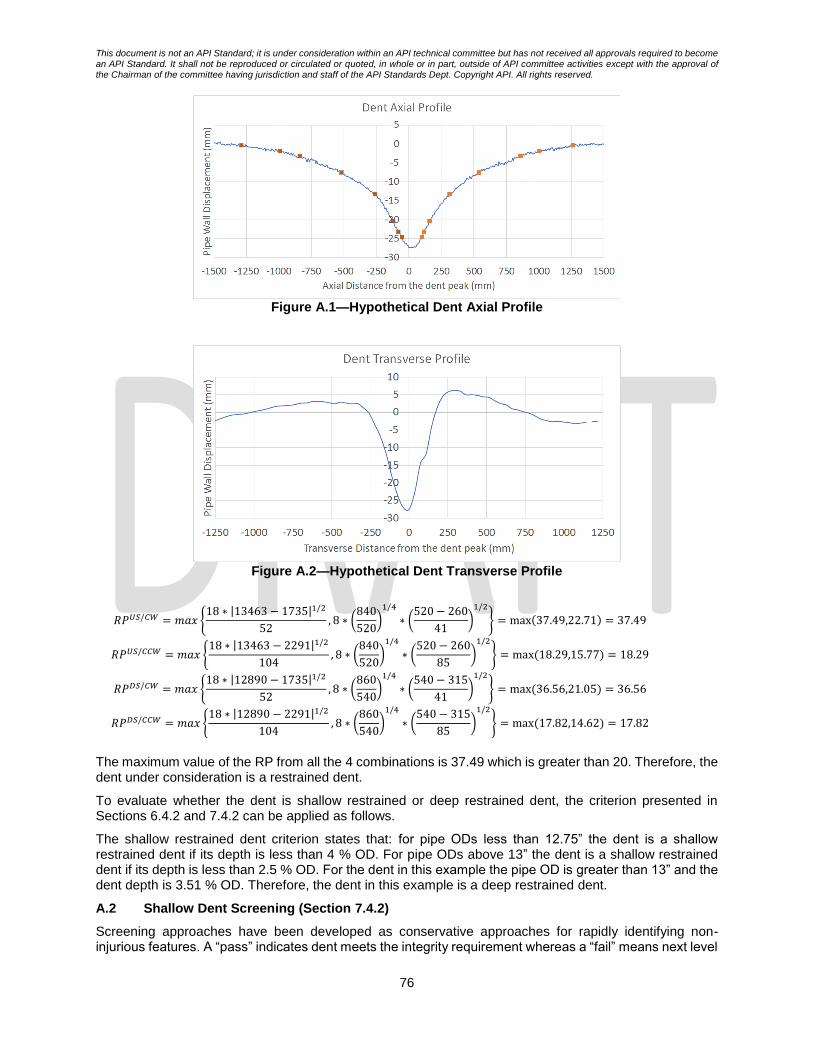
This document is not an API Standard; it is under consideration within an API technical committee but has not received all approvals required to become an API Standard. It shall not be reproduced or circulated or quoted, in whole or in part, outside of API committee activities except with the approval of the Chairman of the committee having jurisdiction and staff of the API Standards Dept. Copyright API. All rights reserved.
76
Figure A.1—Hypothetical Dent Axial Profile
Figure A.2—Hypothetical Dent Transverse Profile
𝑅𝑃𝑈𝑆/𝐶𝑊 = 𝑚𝑎𝑥 {18 ∗ |13463 − 1735|1/2
52, 8 ∗ (
840
520)1/4
∗ (520 − 260
41)1/2
} = max(37.49,22.71) = 37.49
𝑅𝑃𝑈𝑆/𝐶𝐶𝑊 = 𝑚𝑎𝑥 {18 ∗ |13463 − 2291|1/2
104, 8 ∗ (
840
520)1/4
∗ (520 − 260
85)1/2
} = max(18.29,15.77) = 18.29
𝑅𝑃𝐷𝑆/𝐶𝑊 = 𝑚𝑎𝑥 {18 ∗ |12890 − 1735|1/2
52, 8 ∗ (
860
540)1/4
∗ (540 − 315
41)1/2
} = max(36.56,21.05) = 36.56
𝑅𝑃𝐷𝑆/𝐶𝐶𝑊 = 𝑚𝑎𝑥 {18 ∗ |12890 − 2291|1/2
104, 8 ∗ (
860
540)1/4
∗ (540 − 315
85)1/2
} = max(17.82,14.62) = 17.82
The maximum value of the RP from all the 4 combinations is 37.49 which is greater than 20. Therefore, the dent under consideration is a restrained dent.
To evaluate whether the dent is shallow restrained or deep restrained dent, the criterion presented in Sections 6.4.2 and 7.4.2 can be applied as follows.
The shallow restrained dent criterion states that: for pipe ODs less than 12.75” the dent is a shallow restrained dent if its depth is less than 4 % OD. For pipe ODs above 13” the dent is a shallow restrained dent if its depth is less than 2.5 % OD. For the dent in this example the pipe OD is greater than 13” and the dent depth is 3.51 % OD. Therefore, the dent in this example is a deep restrained dent.
A.2 Shallow Dent Screening (Section 7.4.2)
Screening approaches have been developed as conservative approaches for rapidly identifying non-injurious features. A “pass” indicates dent meets the integrity requirement whereas a “fail” means next level

This document is not an API Standard; it is under consideration within an API technical committee but has not received all approvals required to become an API Standard. It shall not be reproduced or circulated or quoted, in whole or in part, outside of API committee activities except with the approval of the Chairman of the committee having jurisdiction and staff of the API Standards Dept. Copyright API. All rights reserved.
77
integrity assessment should be performed. If a feature is not identified as non-injurious, it should be mentioned that this does not mean that the dent possesses an integrity issue, but it requires further investigation based on the next level integrity assessment.
For unrestrained dents, the maximum stress magnification factor 𝐾𝑀𝑀𝑎𝑥, can be related to the pipe geometry,
𝑂𝐷/𝑡, using equations from Section 7.4.2 of the present document. For unrestrained dents that have seen maximum pressure greater than 20% PSMYS pressure the correlation is given by Equation A.2:
𝐾𝑀𝑀𝑎𝑥 = 7.5 ∗ [1 − exp(−0.065 ∗ 𝑂𝐷 𝑡⁄ )] (A.2)
And for unrestrained dents that have not seen maximum pressure greater than 20% PSMYS, the correlation is given by Equation A.3:
𝐾𝑀𝑀𝑎𝑥 = 9.3 ∗ [1 − 𝑒𝑥𝑝(−0.045 ∗ 𝑂𝐷 𝑡⁄ )] (A.3)
Example 2 – Unrestrained Dent
Consider an unrestrained dent with 0.36” depth in the pipe geometry listed in Table A.2.
Table A.2—Pipe Characteristics for Example 2
Parameter Value
Pipe Outer Diameter (OD) 24 in
Pipe Wall Thickness (t) 0.281 in
Pipe Grade X52
SMYS 52000 psi (358 MPa)
Dent Depth (%OD) 1.5%
SSI 100 cycles
Assume that the dent has seen one cycle of hydrotest pressure (90 % PSMYS) since it was formed and existed in the line. The pressure severity spectrum index (SSI) for this line is 100 cycles. The maximum
𝐾𝑀𝑀𝑎𝑥 that can exist in this line for unrestrained dents is given by Equation A.2.
𝐾𝑀𝑀𝑎𝑥 = 7.5 ∗ [1 − exp(−0.065 ∗ 24 0.281⁄ )] = 7.47
For S-N curve definition provided log10 𝐶 = 12.6007 and 𝑚 = 3. For a target life of 𝑌 = 100 years and the
line operational pressure 𝑆𝑆𝐼 = 100, the 𝐾𝑀𝐴𝑙𝑙𝑜𝑤𝑎𝑏𝑙𝑒 is calculated as follows using Equation 11:
𝐾𝑀𝐴𝑙𝑙𝑜𝑤𝑎𝑏𝑙𝑒 = 10[(12.6007−log10(100∗100)]/3 90⁄ =8.18
The dent 𝐾𝑀𝑀𝑎𝑥 < 𝐾𝑀
𝐴𝑙𝑙𝑜𝑤𝑎𝑏𝑙𝑒; therefore, it passes the level 0 integrity assessment for the given operational pressure 𝑆𝑆𝐼 = 100 and the target life of 𝑌 = 100 based on this screening tool.
A.3 Dent Fatigue Life Screening with or Without Operational Pressure Profile Data for Unrestrained Dent (Sections 7.4.2 and 7.4.3)
The dent screening process considering the operational profile (7.4.3) is similar to the screening procedure that does not considering the operational profile data (7.4.2), however, it is less conservatism. It includes the effect of pressure ranges in evaluating the maximum stress magnification factor.
Example 3 – Dent Fatigue Life Screening
Consider an unrestrained dent in a X52 grade pipe (𝜎𝑆𝑀𝑌𝑆 = 358 𝑀𝑃𝑎), with OD/t=30”/0.25”. The detailed pressure data for this line is listed in Table A.3. It is assumed that there are only 3 pressure ranges in the loading spectrum. Using the screening tool SN curve, it is desired to evaluate if the dent meets a desired fatigue life of 𝑌𝑡𝑎𝑟𝑔 = 150 years. The SSI of the given pressure cycle is 100 equivalent 13ksi hoop stress
cycles per year.
Table A.3—Pressure Cycles for Example 3
Cycle #
𝑷𝒎𝒊𝒏 (psi)
𝑷𝒎𝒂𝒙 (psi)
𝑷𝒎𝒊𝒏 (%PSMYS)
𝑷𝒎𝒂𝒙 (%PSMYS)
𝚫𝑷 (%PSMYS)
𝑷𝒎𝒆𝒂𝒏 (%PSMYS)
No of cycles per year (𝒏)
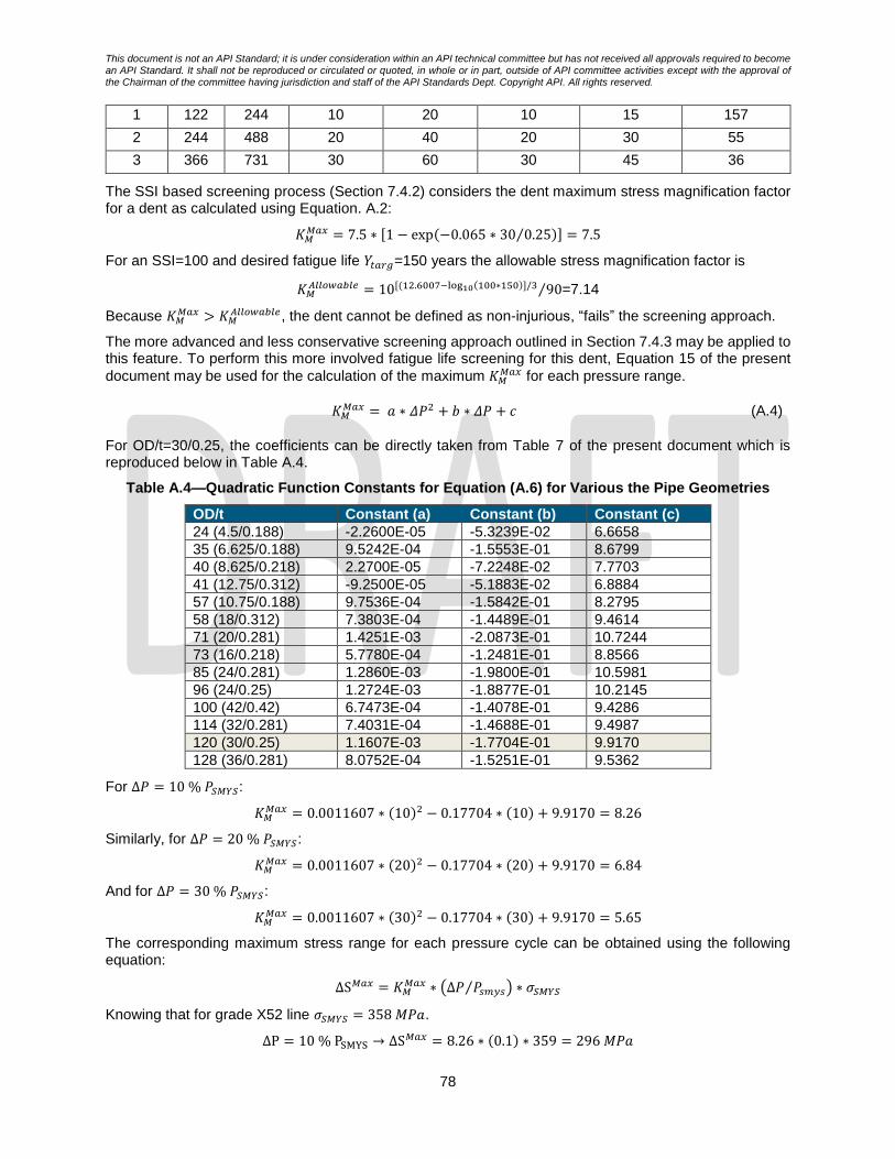
This document is not an API Standard; it is under consideration within an API technical committee but has not received all approvals required to become an API Standard. It shall not be reproduced or circulated or quoted, in whole or in part, outside of API committee activities except with the approval of the Chairman of the committee having jurisdiction and staff of the API Standards Dept. Copyright API. All rights reserved.
78
1 122 244 10 20 10 15 157
2 244 488 20 40 20 30 55
3 366 731 30 60 30 45 36
The SSI based screening process (Section 7.4.2) considers the dent maximum stress magnification factor for a dent as calculated using Equation. A.2:
𝐾𝑀𝑀𝑎𝑥 = 7.5 ∗ [1 − exp(−0.065 ∗ 30 0.25⁄ )] = 7.5
For an SSI=100 and desired fatigue life 𝑌𝑡𝑎𝑟𝑔=150 years the allowable stress magnification factor is
𝐾𝑀𝐴𝑙𝑙𝑜𝑤𝑎𝑏𝑙𝑒 = 10[(12.6007−log10(100∗150)]/3 90⁄ =7.14
Because 𝐾𝑀𝑀𝑎𝑥 > 𝐾𝑀
𝐴𝑙𝑙𝑜𝑤𝑎𝑏𝑙𝑒, the dent cannot be defined as non-injurious, “fails” the screening approach.
The more advanced and less conservative screening approach outlined in Section 7.4.3 may be applied to this feature. To perform this more involved fatigue life screening for this dent, Equation 15 of the present
document may be used for the calculation of the maximum 𝐾𝑀𝑀𝑎𝑥 for each pressure range.
𝐾𝑀𝑀𝑎𝑥 = 𝑎 ∗ 𝛥𝑃2 + 𝑏 ∗ 𝛥𝑃 + 𝑐 (A.4)
For OD/t=30/0.25, the coefficients can be directly taken from Table 7 of the present document which is reproduced below in Table A.4.
Table A.4—Quadratic Function Constants for Equation (A.6) for Various the Pipe Geometries
OD/t Constant (a) Constant (b) Constant (c)
24 (4.5/0.188) -2.2600E-05 -5.3239E-02 6.6658
35 (6.625/0.188) 9.5242E-04 -1.5553E-01 8.6799
40 (8.625/0.218) 2.2700E-05 -7.2248E-02 7.7703
41 (12.75/0.312) -9.2500E-05 -5.1883E-02 6.8884
57 (10.75/0.188) 9.7536E-04 -1.5842E-01 8.2795
58 (18/0.312) 7.3803E-04 -1.4489E-01 9.4614
71 (20/0.281) 1.4251E-03 -2.0873E-01 10.7244
73 (16/0.218) 5.7780E-04 -1.2481E-01 8.8566
85 (24/0.281) 1.2860E-03 -1.9800E-01 10.5981
96 (24/0.25) 1.2724E-03 -1.8877E-01 10.2145
100 (42/0.42) 6.7473E-04 -1.4078E-01 9.4286
114 (32/0.281) 7.4031E-04 -1.4688E-01 9.4987
120 (30/0.25) 1.1607E-03 -1.7704E-01 9.9170
128 (36/0.281) 8.0752E-04 -1.5251E-01 9.5362
For Δ𝑃 = 10 % 𝑃𝑆𝑀𝑌𝑆:
𝐾𝑀𝑀𝑎𝑥 = 0.0011607 ∗ (10)2 − 0.17704 ∗ (10) + 9.9170 = 8.26
Similarly, for Δ𝑃 = 20 % 𝑃𝑆𝑀𝑌𝑆:
𝐾𝑀𝑀𝑎𝑥 = 0.0011607 ∗ (20)2 − 0.17704 ∗ (20) + 9.9170 = 6.84
And for Δ𝑃 = 30 % 𝑃𝑆𝑀𝑌𝑆:
𝐾𝑀𝑀𝑎𝑥 = 0.0011607 ∗ (30)2 − 0.17704 ∗ (30) + 9.9170 = 5.65
The corresponding maximum stress range for each pressure cycle can be obtained using the following equation:
ΔS𝑀𝑎𝑥 = 𝐾𝑀𝑀𝑎𝑥 ∗ (Δ𝑃 𝑃𝑠𝑚𝑦𝑠⁄ ) ∗ 𝜎𝑆𝑀𝑌𝑆
Knowing that for grade X52 line 𝜎𝑆𝑀𝑌𝑆 = 358 𝑀𝑃𝑎.
ΔP = 10 % PSMYS → ΔS𝑀𝑎𝑥 = 8.26 ∗ (0.1) ∗ 359 = 296 𝑀𝑃𝑎

This document is not an API Standard; it is under consideration within an API technical committee but has not received all approvals required to become an API Standard. It shall not be reproduced or circulated or quoted, in whole or in part, outside of API committee activities except with the approval of the Chairman of the committee having jurisdiction and staff of the API Standards Dept. Copyright API. All rights reserved.
79
ΔP = 20 % PSMYS → ΔS𝑀𝑎𝑥 = 6.84 ∗ (0.2) ∗ 359 = 490 𝑀𝑃𝑎
ΔP = 30 % PSMYS → ΔS𝑀𝑎𝑥 = 5.65 ∗ (0.3) ∗ 359 = 607 𝑀𝑃𝑎
Once the maximum stress range for each pressure cycle is calculated the accumulated damage associated to each pressure can be calculated as follows:
𝐷𝑖 = 𝑛𝑖/𝑁𝑖
where 𝑁𝑖 = 10(log10 𝐶−𝑚∗log10 Δ𝑆𝑖
𝑀𝑎𝑥). For the S-N curve used in this screening technique, log10 𝐶=12.6007 and m=3. Therefore, the 1-year cumulative damage for the given pressure cycle is given by
𝐷𝑡𝑜𝑡𝑎𝑙 = 𝐷1 + 𝐷2 + 𝐷3 =157
10(12.6007−3 log10 296)+
55
10(12.6007−3 log10 490)+
36
10(12.6007−3 log10 607)
𝐷𝑡𝑜𝑡𝑎𝑙 = 0.004663
Therefore, the total fatigue life of this dent is given by Ytotal= 1/Dtotal = 214.5 years. Because Ytotal is greater than the desired (target) fatigue life of Ytar (= 150 years) the dent is considered non-injurious based on this screening tool. Table A.5 summarizes the above calculations in a tabular format.
Table A.5—Calculated Level 0.5 Maximum stress magnification factor for Example 3
Sl. no
∆𝑷 (%PSMYS)
No of cycles per year (𝒏)
∆𝑺𝒏𝒐𝒎 (Mpa)
𝑲𝑴𝑴𝒂𝒙 ∆𝑺𝒊 (Mpa) 𝑵𝒊 𝑫𝒊
1 10 157 35.9 8.26 296 153753 0.001021
2 20 55 71.7 6.84 490 33893 0.001623
3 30 36 107.6 5.65 607 17829 0.002019
𝐷𝑡𝑜𝑡𝑎𝑙 0.004663
𝑌𝑡𝑜𝑡𝑎𝑙 =1
𝐷𝑡𝑜𝑡𝑎𝑙 (years) 214.45
A.4 Level 2 (Shape Parameter) Dent Fatigue Life Calculation (Section 8.2.3)
Consider a symmetric dent in a pipeline with the pipe geometry/grade and dent depth listed in Table A.6 and the dent characteristic lengths and areas listed in Table A.7.
Table A.6—Pipe Characteristics for the Level 2 Example Case
Parameter Value
Pipe Outer Diameter (OD) 24 in.
Pipe Wall Thickness (t) 0.281 in.
Pipe Grade X52
SMYS 52000 psi (359 MPa)
Dent Depth (% OD) 1.5 %
SSI 100 cycles
Table A.7—Dent Geometric Lengths and Areas for Example Dent Feature
Designated Length (%Dmax)
Axial Length (𝒎𝒎)
Axial Area (𝒎𝒎𝟐)
Transverse Length (𝒎𝒎)
Transverse
Area (𝒎𝒎𝟐) 85 26.15 12.099 17.605
80 21.579
75 35.899 28.64 25.267 22.082
70 28.955
50 70.497
30 172.3 688.84
15 477.17 2725.8 82.992 308.37
A hypothetical annual pressure cyclic loading for this dent is listed in Table A.8. The objective is to use the shape parameter fatigue life equation and calculate the dent total life for the given pressure cycle.
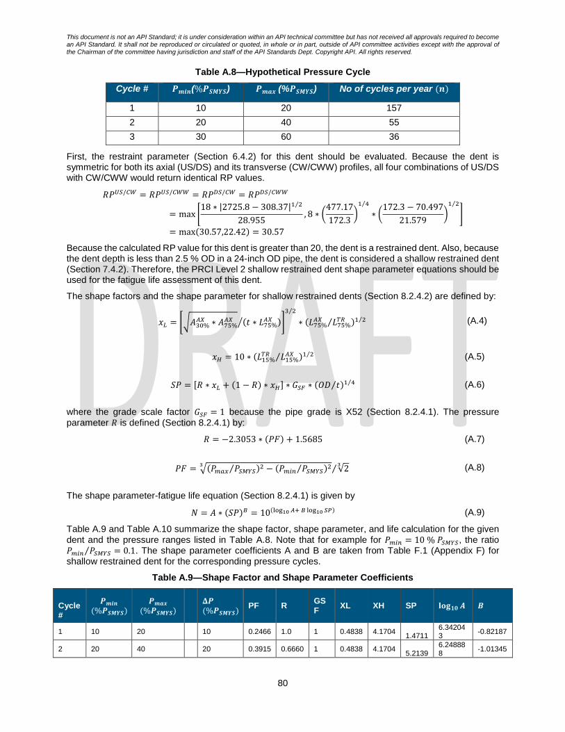
This document is not an API Standard; it is under consideration within an API technical committee but has not received all approvals required to become an API Standard. It shall not be reproduced or circulated or quoted, in whole or in part, outside of API committee activities except with the approval of the Chairman of the committee having jurisdiction and staff of the API Standards Dept. Copyright API. All rights reserved.
80
Table A.8—Hypothetical Pressure Cycle
Cycle # 𝑷𝒎𝒊𝒏(%𝑷𝑺𝑴𝒀𝑺) 𝑷𝒎𝒂𝒙 (%𝑷𝑺𝑴𝒀𝑺) No of cycles per year (𝒏)
1 10 20 157
2 20 40 55
3 30 60 36
First, the restraint parameter (Section 6.4.2) for this dent should be evaluated. Because the dent is symmetric for both its axial (US/DS) and its transverse (CW/CWW) profiles, all four combinations of US/DS with CW/CWW would return identical RP values.
𝑅𝑃𝑈𝑆/𝐶𝑊 = 𝑅𝑃𝑈𝑆/𝐶𝑊𝑊 = 𝑅𝑃𝐷𝑆/𝐶𝑊 = 𝑅𝑃𝐷𝑆/𝐶𝑊𝑊
= max [18 ∗ |2725.8 − 308.37|1 2⁄
28.955, 8 ∗ (
477.17
172.3)1 4⁄
∗ (172.3 − 70.497
21.579)1 2⁄
]
= max(30.57,22.42) = 30.57
Because the calculated RP value for this dent is greater than 20, the dent is a restrained dent. Also, because the dent depth is less than 2.5 % OD in a 24-inch OD pipe, the dent is considered a shallow restrained dent (Section 7.4.2). Therefore, the PRCI Level 2 shallow restrained dent shape parameter equations should be used for the fatigue life assessment of this dent.
The shape factors and the shape parameter for shallow restrained dents (Section 8.2.4.2) are defined by:
𝑥𝐿 = [√𝐴30%𝐴𝑋 ∗ 𝐴75%
𝐴𝑋 (𝑡 ∗ 𝐿75%𝐴𝑋 )⁄ ]
3 2⁄
∗ (𝐿75%𝐴𝑋 𝐿75%
𝑇𝑅⁄ )1 2⁄ (A.4)
𝑥𝐻 = 10 ∗ (𝐿15%𝑇𝑅 𝐿15%
𝐴𝑋⁄ )1 2⁄ (A.5)
𝑆𝑃 = [𝑅 ∗ 𝑥𝐿 + (1 − 𝑅) ∗ 𝑥𝐻] ∗ 𝐺𝑆𝐹 ∗ (𝑂𝐷 𝑡⁄ )1 4⁄ (A.6)
where the grade scale factor 𝐺𝑆𝐹 = 1 because the pipe grade is X52 (Section 8.2.4.1). The pressure
parameter 𝑅 is defined (Section 8.2.4.1) by:
𝑅 = −2.3053 ∗ (𝑃𝐹) + 1.5685 (A.7)
𝑃𝐹 = √(𝑃𝑚𝑎𝑥 𝑃𝑆𝑀𝑌𝑆⁄ )2 − (𝑃𝑚𝑖𝑛 𝑃𝑆𝑀𝑌𝑆⁄ )23
√23 ⁄ (A.8)
The shape parameter-fatigue life equation (Section 8.2.4.1) is given by
𝑁 = 𝐴 ∗ (𝑆𝑃)𝐵 = 10(log10 𝐴+ 𝐵 log10 𝑆𝑃) (A.9)
Table A.9 and Table A.10 summarize the shape factor, shape parameter, and life calculation for the given dent and the pressure ranges listed in Table A.8. Note that for example for 𝑃𝑚𝑖𝑛 = 10 % 𝑃𝑆𝑀𝑌𝑆, the ratio 𝑃𝑚𝑖𝑛 𝑃𝑆𝑀𝑌𝑆⁄ = 0.1. The shape parameter coefficients A and B are taken from Table F.1 (Appendix F) for shallow restrained dent for the corresponding pressure cycles.
Table A.9—Shape Factor and Shape Parameter Coefficients
Cycle #
𝑷𝒎𝒊𝒏 (%𝑷𝑺𝑴𝒀𝑺)
𝑷𝒎𝒂𝒙 (%𝑷𝑺𝑴𝒀𝑺)
𝚫𝑷 (%𝑷𝑺𝑴𝒀𝑺)
PF R GSF
XL XH SP 𝐥𝐨𝐠𝟏𝟎 𝑨 𝑩
1 10 20
10 0.2466 1.0 1 0.4838 4.1704 1.4711
6.342043
-0.82187
2 20 40
20 0.3915 0.6660 1 0.4838 4.1704 5.2139
6.248888
-1.01345

This document is not an API Standard; it is under consideration within an API technical committee but has not received all approvals required to become an API Standard. It shall not be reproduced or circulated or quoted, in whole or in part, outside of API committee activities except with the approval of the Chairman of the committee having jurisdiction and staff of the API Standards Dept. Copyright API. All rights reserved.
81
3 30 60
30 0.5130 0.3859 1 0.4838 4.1704 8.3533
5.831431
-0.83388
Table A.10—Damage Calculation
Cycle #
𝑷𝒎𝒊𝒏 (%𝑷𝑺𝑴𝒀𝑺)
𝑷𝒎𝒂𝒙 (%𝑷𝑺𝑴𝒀𝑺)
𝚫𝑷
(%𝑷𝑺𝑴𝒀𝑺) No of cycles per year (𝒏)
𝑵 = 𝟏𝟎(𝐥𝐨𝐠𝟏𝟎 𝑨+𝑩 𝐥𝐨𝐠𝟏𝟎 𝑺𝑷) 𝑫𝒊 = 𝒏𝒊 𝑵𝒊⁄
Damage
1 10 20 10 157 1,600,521 9.81E-05
2 20 40 20 55 332,717 0.000165
3 30 60 30 36 115,535 0.000312
Therefore, the annual cumulative damage is ∑ 𝐷𝑖3𝑖=1 = 0.000575 which returns the dent total life of 𝑌𝐷𝑒𝑛𝑡 =
1
𝐷1+𝐷2+𝐷3= 1739.2 years.

This document is not an API Standard; it is under consideration within an API technical committee but has not received all approvals required to become an API Standard. It shall not be reproduced or circulated or quoted, in whole or in part, outside of API committee activities except with the approval of the Chairman of the committee having jurisdiction and staff of the API Standards Dept. Copyright API. All rights reserved.
82
Appendix B
Dent Crack Initiation Surface, Location, Orientation and Form
(informative)
Field observations, full-scale testing, and numerical simulation have demonstrated trends in the location, initiation surface, orientation, and form of fatigue cracking developed in dent features. The information provided in Table B.1 may prove useful in support of analyzing ILI and in-ditch non-destructive examination (NDE) data, enhancing existing and supporting the development of ILI and NDE inspection systems, improving ILI data analysis procedures, and improving in-ditch dent inspection procedures. In this figure the nature of cracking that could be developed in-service are described. To make use of this information, the restraint condition the pipeline should be defined and the depth of the dent feature should be considered.
In Table B.1, shallow dents are defined as:
- Depth < 4 % of the pipe diameter [for OD ≤ 12.75 in. (324 mm)] - Depth < 2.5 % of the pipe diameter [for OD > 12.75 in. (324 mm)]
Table B.1 – Photographs showing fatigue crack location and orientation relative to the depth and restraint condition of a dent. The photographs shown are cracks generated during full-scale
pressure cycling fatigue test trials completed in a laboratory.

This document is not an API Standard; it is under consideration within an API technical committee but has not received all approvals required to become an API Standard. It shall not be reproduced or circulated or quoted, in whole or in part, outside of API committee activities except with the approval of the Chairman of the committee having jurisdiction and staff of the API Standards Dept. Copyright API. All rights reserved.
83
Appendix C
Field Guidance Listing
(informative)
The following section presents a description of the data to be gathered during field dig investigations to support structural integrity assessments. The list of information presented in each section of the guide represents the ideal set of data to be used during an assessment and therefore is intended to provide as much information as possible. In many instances, gathering a particular type of data may not be practical. Where the data is considered necessary, it is shaded grey in the guide.
C.1 General Excavation Information
The following summarizes the information to be gathered in the field prior to the commencement of digging operations.
C.1.1 General Surrounding Observations
a. Record ambient conditions (i.e. temperature) b. General photos of the pipeline right-of-way upstream and downstream of the proposed dig
location c. General topography
i. Slope ii. Description of terrain (e.g., farmland, forest, rocky, etc.) iii. Description of the state of local vegetation iv. Bodies of water nearby v. Free or supported spans
d. Note any evidence of subsidence or other ground movement e. Proximity of bends upstream and downstream of proposed dig location f. Internal pressure in the pipeline during excavation
C.1.2 Observations During Excavation
The dig should be carried out in a staged manner where the overburden is removed first until the top of the pipe is reached. As the excavation proceeds gather information regarding:
a. Photos at various intervals throughout the excavation process b. Note any debris or rocks that are removed during the excavation particularly from the top of the
pipe c. Type of soil d. Soil condition (moisture levels) e. Soil pH level f. Describe the soil compaction level next to the pipe g. Describe the backfill material h. Rockshield type wrap included on pipe i. Cathodic protection
C.1.3 Observations Completion of Excavation
Once the excavation has been completed and the pipeline fully exposed, document the trench:
a. Photos of the trench b. Description and measurements of the trench shape (e.g., length, width, depth) c. Document the depth of cover to the top of the pipe
C.2 Condition of Pipeline

This document is not an API Standard; it is under consideration within an API technical committee but has not received all approvals required to become an API Standard. It shall not be reproduced or circulated or quoted, in whole or in part, outside of API committee activities except with the approval of the Chairman of the committee having jurisdiction and staff of the API Standards Dept. Copyright API. All rights reserved.
84
Once exposed the condition of the pipeline and coating should be recorded.
C.2.1 Condition of The Pipeline Coating
a. Photos of coating along the entire exposed pipe b. Type of coating and thickness c. Evidence of coating holidays d. Tenting of coating over welds e. Coating repairs
C.2.2 General Condition of Pipeline
Once the coating is removed record:
a. Photos of surface of pipeline with chainage notes and flow direction noted b. If applicable note any repairs to the pipe
i. Sleeves ii. Weld repairs
c. General condition of pipeline surface
C.2.4 Detailed Condition of Pipeline
Once exposed, the detailed condition of the pipe should be recorded.
a. Note any external surface features i. Type of feature (corrosion, pitting, gouge, etc) ii. Size of feature (length, width, depth) iii. Photos of feature including a scale iv. Location of feature w.r.t. closest girth weld and long seam weld
b. Carry out UT thickness measurement survey (12:00, 3:00, 6:00 and 9:00) c. Carry out Magnetic Particle Inspection (MPI) to identify any OD surface breaking cracks d. Carry out UT crack detection for circumferential and axially oriented cracks e. Document any existing cracks
i. Size (length, depth) ii. Clock Position iii. Location w.r.t. girth welds iv. Orientation (i.e. circumferential, axial or angle w.r.t. longitudinal axis)
f. For detailed non-destructive material property characterization, the following should be collected (specialized NDE personnel may be required):
i. In-situ hardness on the pipe OD surface ii. Shavings from the pipe OD surface (for characterizing chemistry) iii. A description of the microstructure (replica)
C.3 Feature Specific Information
The following section presents information to be gathered for features being investigated.
C.3.1 Corrosion Features
a. Photos of corrosion features including a scale b. Type of corrosion c. Feature size(s) (i.e. length, width, depth)
i. Laser scan if available d. Location of features
i. W.r.t. closest girth weld ii. Clock position iii. Proximity to adjacent features (i.e. other corrosion features, girth or seam welds)
e. Obtain and save a corrosion product sample f. Obtain a pH sample from the soil close to the pipe surface g. Document cathodic protection conditions

This document is not an API Standard; it is under consideration within an API technical committee but has not received all approvals required to become an API Standard. It shall not be reproduced or circulated or quoted, in whole or in part, outside of API committee activities except with the approval of the Chairman of the committee having jurisdiction and staff of the API Standards Dept. Copyright API. All rights reserved.
85
C.3.2 Dents
For a field investigation of a dent feature the following information should be recorded where possible.
a. Photos of dent including a scale (record the length of the straight edge used (Longer straight edge preferred)
b. c. If possible, laser scan the pipe surface including the dent feature d. Location of dent feature
i. W.r.t. closest girth weld ii. Clock position iii. Proximity to adjacent features (i.e. other corrosion features, girth or seam welds)
e. For bottom side dents i. Note the existence of any rocklike indenters during excavation ii. Photos of pipe and rock prior to removal of rock iii. Note size of rock iv. Identify and keep rock if possible (indicate on the rock the contact surface)
f. Record axial profile of dent through deepest point and at clock positions either side of deepest point
i. Place a long straight edge (record length of straight edge) along pipe wall surface in-line with deepest point in the dent
ii. Measure depth at the deepest point and at 2 in. intervals along upstream and downstream length of dent
g. Measure ovality at the 3-9 o’clock positions (w.r.t. dent clock position) i. At the dent center ii. At the two ends of the straight edge used to measure the axial profiles
C.3.3 Wrinkles
For a field investigation of a wrinkle the following information should be recorded where possible.
a. Photos of wrinkle including a scale b. If possible laser scan the pipe surface including the wrinkle c. Location of wrinkle
a. W.r.t. closest girth weld b. Clock position c. Proximity to adjacent features (i.e. other corrosion features, girth or seam welds)
d. Record axial profile of wrinkle at each clock position a. Place a long straight edge (record length of straight edge) along pipe wall surface (equal
height blocks may be required to elevate straight edge over wrinkle peak) b. Measure depth at 2 in. intervals along upstream and downstream length of pipe
e. Measure ovality at the 3 & 9 o’clock positions (w.r.t. wrinkle peak clock position) a. At the center of the wrinkle b. At the two ends of the straight edge used to measure the axial profiles
C.4 Best Practices – Photography
When taking photographs in the field, the following practices should be used.
a. Pair local photos with global photos of the entire exposed pipe b. Each photo should be named and included in a descriptive list of all the photos taken during the
field investigation c. Pipe should be labeled legibly in each photo with
i. Line Number / Name ii. Chainage (milepost, etc) iii. Flow Direction iv. Feature description v. Include a scale in each photo vi. Cut lines and pipe segment numbers if being cutout and removed

This document is not an API Standard; it is under consideration within an API technical committee but has not received all approvals required to become an API Standard. It shall not be reproduced or circulated or quoted, in whole or in part, outside of API committee activities except with the approval of the Chairman of the committee having jurisdiction and staff of the API Standards Dept. Copyright API. All rights reserved.
86

This document is not an API Standard; it is under consideration within an API technical committee but has not received all approvals required to become an API Standard. It shall not be reproduced or circulated or quoted, in whole or in part, outside of API committee activities except with the approval of the Chairman of the committee having jurisdiction and staff of the API Standards Dept. Copyright API. All rights reserved.
87
ANNESX D
Effect Of Axial Loads on Dents [This section left intentionally blank]

This document is not an API Standard; it is under consideration within an API technical committee but has not received all approvals required to become an API Standard. It shall not be reproduced or circulated or quoted, in whole or in part, outside of API committee activities except with the approval of the Chairman of the committee having jurisdiction and staff of the API Standards Dept. Copyright API. All rights reserved.
88
ANNEX E
Capabilities of In-line Inspection systems for Plain Dents and Specific Types of Coincident Features and Interacting Defects
(informative)
This appendix presents a summary of the ILI systems and sensing technologies that can detect and characterize dents and dents with coincident features. The ILI systems are described in general terms and the information presented is focused on detecting and characterizing dents and other features that may be coincident to and/or interacting with the dent. The detection, proper identification, and sizing of certain coincident features is a critical part of the dent assessment and integrity management process.
Additional discussion of ILI systems for assessment and management of pipeline features is included in Section 9.2 and Appendix B of API RP 1160. There are other API RPs that address ILI systems and their applications to dent assessment and management, including Standard 1163, ILI System Qualification, and RP 1176, Recommended Practice for Assessment and Management of Cracking in Pipelines.
The pipeline industry continues to conduct research and to support the development of new technologies through industry organizations such as PRCI and research programs funded by PHMSA. Revisions to this RP may be considered if there are any significant improvements in the understanding of ILI systems’ performance and the development of new technologies that improve pipeline operators’ ability to detect and characterize dents and to discriminate and size coincident features. ILI systems technology developers and service providers conduct a significant level of internally funded research to improve their commercial systems capability regarding detection and discrimination of features and improving feature sizing.
E.1 Plain Dents
E1.1 Geometry Tools
ILI tools for estimating dent geometry use various techniques to measure the position of the pipe wall with respect to the tool. Examples include:
- mechanical caliper arms, either in direct contact with the pipe wall or behind a support cup surface - eddy current sensors - ultrasonic sensors
Some implementations use combinations of these techniques. In general, geometry tools collect a series of cross sections as the tool moves axially down the pipe, which when viewed together create a 3D representation of the inner pipe surface, providing a detailed view of the large-scale shape of dents and other geometric features.
There are thresholds on geometry tools capability to identify the point where the pipe wall has return to the nominal diameter position. The extent of these thresholds will be dependent on sensor sensitivity, tool dynamics and pipe conditions. This is further complicated by the fact that large diameter pipeline will often take an ovality set during pipe installation simply due to loading under its own weight.
E1.2 High Field MFL Tools
Magnetic Flux Leakage (MFL) uses the ferromagnetic property of pipeline steel to perform an inspection. A magnetic field is introduced into the steel wall of the pipe using two pairs of magnets, one with its north pole near the surface of the pipe and the other with the south pole near the surface of the pipe. These magnets are usually permanent magnets, but electromagnets have been used as well. Permanent magnets have the advantage of having a known magnetizing force that varies predictably with wall thickness and pipe material while requiring no power. Electromagnets require electric current and the field strength can be adjusted by changing the current. To induce magnetic flux into the pipe, some configurations use a permeable steel brush material is used to facilitate the magnetic induction into the pipe while others leave an air gap but situate the magnet close to the surface.
This document is not an API Standard; it is under consideration within an API technical committee but has not received all approvals required to become an API Standard. It shall not be reproduced or circulated or quoted, in whole or in part, outside of API committee activities except with the approval of the Chairman of the committee having jurisdiction and staff of the API Standards Dept. Copyright API. All rights reserved.
89
Once magnetic flux is in the pipe, changes in the pipe permeability will cause changes in the amplitude of the flux. For metal loss, such a corrosion, the volume of lost steel has much lower permeability and cannot support as much flux as the steel, thus it “leaks” out into the space outside of the pipe, both internally and externally which allows for detection and sizing of anomalies on both sides of the pipe. MFL tools place sensors in this region, usually Hall sensors which use the Hall Effect to measure the strength of the magnetic field at the sensor. Coil sensors have been used, which require no power, but do require movement through the magnetic field to induce a voltage across the area of the coil.
The direction of magnetization is important as the MFL signal is greatest when the perpendicular edge of an anomaly has large extent and depth. There are two main categories of magnetization: Axial, Transverse (circumferential or helical).
E1.2.1 Axial MFL
Axial magnetization is created when an ILI tool’s magnets are placed in a ring-like configuration at the front and back of the tool; each ring having the opposite polarization to the other. Between the two magnetic poles the sensors are placed where the magnetization is completely or mostly aligned in the axial direction. Metal loss with circumferential extent and appreciable depth will disrupt the flux creating MFL measured by the sensors.
In a dent inspection, axial magnetization is used for detecting and sizing metal loss that are not axially aspected. It can also detect gouges that are not axially oriented. As for interacting threats, girth welds are easily detected using the axial field. Seam welds are usually not detectable depending on seam geometry and magnetic properties. For deeper dents, the sensor arm will be displaced and depending on the magnetic performance of the tool, it will measure the near the tool body as well as be rotated in the applied axial field, measuring a reduction in the applied field near the pipe wall.
E1.2.2 Transverse (Circumferential or Helical) MFL
To overcome the limitations of axial magnetization, an ILI tool can be designed to induce a magnetization in a transverse direction of the pipe. There are several designs that can accomplish this, but the basic principle is to locate the opposing magnetic poles transversely (circumferentially or helically) from each other. The number of poles can vary but they must always be in multiples of two so that each pole has an opposite pole on either side of it so that the flux lines will travel transversely to the opposite pole. By having the field in this direction, the tool can detect and size axially aspected anomalies while circumferentially aspected are less likely to be detected and sized correctly; therefore, axial magnetizers and transverse magnetizers are usually run together.
In dent inspection, the transverse magnetizer can detect and size axial metal loss within a dent as well as axially oriented gouging. The transverse magnetizer can detect the seam weld and identify if it is interacting with a dent.
E1.3 Residual & Low Field MFL
Residual (RES) of Low Field MFL (LFM) also use the ferromagnetic property of pipeline steel to perform an inspection, similar to high field MFL. The difference is the level of magnetization. Where high field MFL provides a field level so that the pipe wall material is magnetically saturated, the RES and LFM technologies either relies on the residual magnetic field from the high field MFL (RES) or provides a lower then saturation field strength (LFM) to detect pipe material property changes. These technologies can be useful for the detection and characterization of coincident features and interacting defects such as hard spots and gouging in dents resulting in localized residual stresses.
E1.4 Ultrasonic Tools
Most of the ultrasonic (UT) technology ILI tools are focused on the detection and identification of metal loss (UTWM) or crack anomalies (UTCD), this will entirely depend on the ultrasonic sensor carrier arrangement. The sensor carrier is optimized to hold the ultrasonic sensor as closer to the inner wall of the pipe, minimizing the stand-off and improving the time-of-flight. As the ultrasonic transducer passes over a deformation, the ultrasonic data will show lift-off and the signals are interpreted as deformation.
A different sensor carrier arrangement is used and optimized that allow the accurate detection and measurement of deformations. This sensor carrier holds the ultrasonic transducers in a fixed and larger

This document is not an API Standard; it is under consideration within an API technical committee but has not received all approvals required to become an API Standard. It shall not be reproduced or circulated or quoted, in whole or in part, outside of API committee activities except with the approval of the Chairman of the committee having jurisdiction and staff of the API Standards Dept. Copyright API. All rights reserved.
90
distance to the pipeline wall, therefore, the lift-off effect is not affecting the measurement. When the ultrasonic transducer passes a pipeline section with a deformation the stand-off distance decrement is recorder, therefore, the accurate shape of the dent and the complete pipeline cross section.
E1.5 Multiple Datasets
ILI vendors are increasingly offering ILI tools with multiple inspection technologies on a single tool chassis. These tools offer reduced inspection costs and data that is fully integrated between on-board technologies. This capability is particularly helpful in identifying coincident features and interacting threats, such as mechanical damage. Some vendors offer a modular approach to tool design that allows operators the flexibility to pick which inspection technologies they want included in the inspection run. The combination of multiple inspection technologies can result in the ILI vendors being able to provide additional detection, classification and sizing.
E.2 Coincident Features and Interacting Defects
E2.1 Metal Loss Features
Dents with metal loss can be identified using a geometry tool and an MFL tool. The geometry will measure the internal surface profile of the dent and magnetism will follow the contour of the deformed pipeline steel without leakage until it is interrupted by a permeability change, i.e. metal loss. The flux leakage from the metal loss anomalies can be measured whether it is on the inner surface or outer surface of the pipe.
E2.2 Gouge Features
To separate corrosion metal loss from gouging, it is optimal to use additional modalities such as transverse magnetization and LFM. The transverse field can detect the sharp edges characteristic of gouges that may be missed by axial magnetization if the gouging is axially aligned. LFM is sensitive to the permeability changes that occur when the steel is hardened as happens during gouging. The combination of observed metal loss in MFL and significant permeability variations in LFM can indicate that an anomaly is more likely to be a gouge versus corrosion.
E2.3 Crack Features
Dents with cracks usually require inspection with a geometry tool and a crack detection technology. The geometry will measure the internal surface profile of the dent and the crack tool, depending on tool design, may follow the contour of the deformed pipe wall looking for reflection signals associated with a crack face.
MFL technologies are not known for crack detection, although detection of crack-like defects has been documented. The crack opening of the axially oriented crack-like feature can be detected by transverse MFL tools when the opening exceeds the threshold specification of the ILI vendor. Similarly, circumferential crack-like features can be detected by traditional axial MFL tools under similar conditions. Depth sizing of crack-like defects will not be available for MFL technologies.
There are two common ILI crack detection technologies: liquid-coupled angle beam ultrasonic methods (UTCD) and Electromagnetic Acoustic Transducer (EMAT). In dent inspection, these technologies can detect and size interacting crack defects.
E2.3.1 UTCD
Liquid-coupled ultrasonic tools (UT) generate ultrasonic pulses in a series of UT sensors, arranged on sensor carriers, that leverage a liquid couplant to transmit the pulses to the pipe wall. The UT pulses travels through the pipe material until it encounters a crack face, at which point a portion of the UT pulses will be reflected to the UT sensors.
E2.3.2 EMAT
EMAT leverage physics associated with magnetics to induce an acoustic wave into the pipe wall, without the need of a liquid couplant. The wave propagates through the pipe wall and, when a crack face is encountered, a portion of the acoustic wave will reflect to a receiver sensors.

This document is not an API Standard; it is under consideration within an API technical committee but has not received all approvals required to become an API Standard. It shall not be reproduced or circulated or quoted, in whole or in part, outside of API committee activities except with the approval of the Chairman of the committee having jurisdiction and staff of the API Standards Dept. Copyright API. All rights reserved.
91
Annex F
PRCI Dent Fatigue Shape Parameters
(informative)
Table F.1—Shape Parameter Coefficients for Restrained Dents
Restrained Dents
Pressure Range (%
SMYS)
Pmin (% SMYS)
Pmax (% SMYS)
Log10(A) B
10 to 20 10 20 6.087286 -0.77295
10 to 30 10 30 5.284836 -0.66188
10 to 40 10 40 4.86638 -0.58546
10 to 50 10 50 4.577582 -0.54968
10 to 60 10 60 4.338077 -0.54343
10 to 70 10 70 4.105337 -0.56648
10 to 80 10 80 3.82946 -0.61641
20 to 30 20 30 6.180877 -0.72782
20 to 40 20 40 5.357296 -0.65343
20 to 50 20 50 4.892771 -0.60479
20 to 60 20 60 4.540423 -0.58269
20 to 70 20 70 4.245734 -0.6
20 to 80 20 80 3.941286 -0.65073
30 to 40 30 40 6.249759 -0.67577
30 to 50 30 50 5.376493 -0.63269
30 to 60 30 60 4.859268 -0.60247
30 to 70 30 70 4.475213 -0.62255
30 to 80 30 80 4.134066 -0.67052
40 to 50 40 50 6.283445 -0.63181
40 to 60 40 60 5.371298 -0.61886
40 to 70 40 70 4.839027 -0.63132
40 to 80 40 80 4.423944 -0.67102
50 to 60 50 60 6.309135 -0.61952
50 to 70 50 70 5.392675 -0.63811
50 to 80 50 80 4.833223 -0.66914
60 to 70 60 70 6.35062 -0.62842
60 to 80 60 80 5.413163 -0.65909
70 to 80 70 80 6.376762 -0.63151

This document is not an API Standard; it is under consideration within an API technical committee but has not received all approvals required to become an API Standard. It shall not be reproduced or circulated or quoted, in whole or in part, outside of API committee activities except with the approval of the Chairman of the committee having jurisdiction and staff of the API Standards Dept. Copyright API. All rights reserved.
92
Table F.2—Shape Parameter Coefficients for Unrestrained Dents
Unrestrained Dents
Pressure Range (% SMYS)
Pmin (% SMYS)
Pmax (% SMYS)
Log10(A) B
10 to 20 10 20 6.06056 -0.42298
10 to 30 10 30 5.185339 -0.4034
10 to 40 10 40 4.710772 -0.38507
10 to 50 10 50 4.350554 -0.37482
10 to 60 10 60 4.081167 -0.37004
10 to 70 10 70 3.828039 -0.37077
10 to 80 10 80 3.609095 -0.37555
20 to 30 20 30 6.122761 -0.36971
20 to 40 20 40 5.238399 -0.35799
20 to 50 20 50 4.744808 -0.3502
20 to 60 20 60 4.367731 -0.35287
20 to 70 20 70 4.076046 -0.36202
20 to 80 20 80 3.805938 -0.37167
30 to 40 30 40 6.189955 -0.34065
30 to 50 30 50 5.302041 -0.33377
30 to 60 30 60 4.785542 -0.33876
30 to 70 30 70 4.391269 -0.35152
30 to 80 30 80 4.078931 -0.36623
40 to 50 40 50 6.24797 -0.32808
40 to 60 40 60 5.343139 -0.33294
40 to 70 40 70 4.807008 -0.34685
40 to 80 40 80 4.395436 -0.3628
50 to 60 50 60 6.278721 -0.32954
50 to 70 50 70 5.364313 -0.34184
50 to 80 50 80 4.803239 -0.36315
60 to 70 60 70 6.299545 -0.33787
60 to 80 60 80 5.360145 -0.36003
70 to 80 70 80 6.288769 -0.356

This document is not an API Standard; it is under consideration within an API technical committee but has not received all approvals required to become an API Standard. It shall not be reproduced or circulated or quoted, in whole or in part, outside of API committee activities except with the approval of the Chairman of the committee having jurisdiction and staff of the API Standards Dept. Copyright API. All rights reserved.
93
Annex G
Scaling Factors for Unrestrained Dent Shape Factors in Equation 12
(informative)
Depending on the pressure cycle that the fatigue life must be calculated to, and also on the ILI pressure at which the ILI profile was measured, different scaling factors must be used for finding the shape factors of a given unrestrained dents as defined in Equation 12.
The first step to identify the correct scale factor for a given pressure cycle, is to find out the Truncated Mean Pressure, TMP, of the cycle and the Rounded ILI Pressure, RILIP, using Equation G.1, Equation G.2, and Equation G.3:
Pmean%𝑃𝑠𝑚𝑦𝑠
= (𝑃𝑚𝑎𝑥 + 𝑃𝑚𝑖𝑛2 ∗ 𝑃𝑆𝑀𝑌𝑆
) ∗ 100
TMP = trunc(Pmean%𝑃𝑠𝑚𝑦𝑠
, 10) = int(Pmean%𝑃𝑠𝑚𝑦𝑠
/10) ∗ 10
RILIP = round(PILI%𝑃𝑠𝑚𝑦𝑠
, 10) = 10 ∗ Round(PILI%𝑃𝑠𝑚𝑦𝑠
/10)
(G.1) (G.2) (G.3)
Where, "int" indicates the integer part of a real number, e.g., int(4.75) = 4 And "round" indicates the closest integer number to the given number, e.g., Round(4.6) = 5.
As an example, for a given cyclic pressure with maximum pressure 37% PSMYS and minimum pressure 22% PSMYS, the TMP value of this pressure cycle is:
Pmean%𝑃𝑠𝑚𝑦𝑠
= (0.37 ∗ 𝑃𝑆𝑀𝑌𝑆 + 0.22 ∗ 𝑃𝑆𝑀𝑌𝑆
2 ∗ 𝑃𝑆𝑀𝑌𝑆) ∗ 100 = 29.5
TMP = trunc(Pmean%𝑃𝑠𝑚𝑦𝑠
, 10) = 10 ∗ int (29.5
10) = 10 ∗ 2 = 20
Similarly, if the ILI pressure, at which the dent profile is measured, is 54.5 % PSMYS, the rounded ILI pressure, RILIP, is:
RILIP = round(PILI%𝑃𝑠𝑚𝑦𝑠
, 10) = 10 ∗ round (54.5
10) = 10 ∗ 5 = 50
Once both the TMP and RILIP are found for the given pressure cycle and the ILI pressure, F.1 to F.7 can be used for finding the corresponding scaling factors.
Table G.1—Scale Factors for the Truncated Mean Pressure (TMP)=10
Rounded ILI Pressure (RILIP)
10 20 30 40 50 60 70
𝜆𝐻 1.0000 1.0855 1.1505 1.2063 1.2774 1.3005 1.3853
𝜆𝐿 1.0000 1.1294 1.2640 1.3498 1.4450 1.5449 1.5860
Table G.2—Scale Factors for the Truncated Mean Pressure (TMP)=20
Rounded ILI Pressure (RILIP)
10 20 30 40 50 60 70
𝜆𝐻 0.9208 1.0000 1.0611 1.1062 1.1767 1.2173 1.2447
𝜆𝐿 0.8836 1.0000 1.0926 1.1765 1.2476 1.3023 1.3744

This document is not an API Standard; it is under consideration within an API technical committee but has not received all approvals required to become an API Standard. It shall not be reproduced or circulated or quoted, in whole or in part, outside of API committee activities except with the approval of the Chairman of the committee having jurisdiction and staff of the API Standards Dept. Copyright API. All rights reserved.
94
Table G.3—Scale Factors for the Truncated Mean Pressure (TMP)=30
Rounded ILI Pressure (RILIP)
10 20 30 40 50 60 70
𝜆𝐻 0.8690 0.9408 1.0000 1.0427 1.0836 1.1334 1.1537
𝜆𝐿 0.8205 0.9239 1.0000 1.0719 1.1343 1.1836 1.2515
Table G.4—Scale Factors for the Truncated Mean Pressure (TMP)=40
Rounded ILI Pressure (RILIP)
10 20 30 40 50 60 70
𝜆𝐻 0.8279 0.8937 0.9573 1.0000 1.0361 1.0794 1.1009
𝜆𝐿 0.7766 0.8712 0.9382 1.0000 1.0577 1.1097 1.1548
Table G.5—Scale Factors for the Truncated Mean Pressure (TMP)=50
Rounded ILI Pressure (RILIP)
10 20 30 40 50 60 70
𝜆𝐻 0.7924 0.8556 0.9282 0.9624 1.0000 1.0453 1.0719
𝜆𝐿 0.7261 0.8290 0.8870 0.9483 1.0000 1.0517 1.0953
Table G.6—Scale Factors for the Truncated Mean Pressure (TMP)=60
Rounded ILI Pressure (RILIP)
10 20 30 40 50 60 70
𝜆𝐻 0.7623 0.8247 0.8970 0.9367 0.9665 1.0000 1.0240
𝜆𝐿 0.6942 0.7921 0.8480 0.9053 0.9527 1.0000 1.0394
Table G.7—Scale Factors for the Truncated Mean Pressure (TMP)=70
Rounded ILI Pressure (RILIP)
10 20 30 40 50 60 70
𝜆𝐻 0.7375 0.7940 0.8682 0.9083 0.9397 0.9702 1.0000
𝜆𝐿 0.6678 0.7511 0.8114 0.8665 0.9125 0.9521 1.0000


![Numerical modelling of hot polymer-coated steel pipeline ... · geometry of the chamfer is designed in accordance with DNV-RP-F102 [7] and DNV-RP-F106 [8] pipeline standards. After](https://static.fdocuments.net/doc/165x107/60ff50993140d62a7a08ed8c/numerical-modelling-of-hot-polymer-coated-steel-pipeline-geometry-of-the-chamfer.jpg)