
DENISON CALZONI Radial Piston Motor Type MR, MREhydraser.com.ar/Catalogos pdf/Bombas a...
36
DENISON CALZONI Radial Piston Motor Type MR, MRE RCOa 1806/03.03
Transcript of DENISON CALZONI Radial Piston Motor Type MR, MREhydraser.com.ar/Catalogos pdf/Bombas a...

DENISON CALZONIRadial Piston Motor
Type MR, MRE
RCOa 1806/03.03
2RCOa 1806/03.03
TABLE OF CONTENTS - MOTOR TYPE MR - MRE
CONTENTS PAG.
TABLE OF CONTENTS 2
GENERAL CHARACTERISTICS 3
FUNCTIONAL DESCRIPTION 4
TECHNICAL DATA 5
FLUID SELECTION 6
FLUSHING PROCEDURE 7
OPERATING DIAGRAM MOTOR TYPE MR 33 MR 57 MR 73 8
OPERATING DIAGRAM MOTOR TYPE MR 93 MR 110 MR 125 9
OPERATING DIAGRAM MOTOR TYPE MR 160 MR 190 MR 200 10
OPERATING DIAGRAM MOTOR TYPE MR 250 MR 300 MRE 330 11
OPERATING DIAGRAM MOTOR TYPE MR 350 MR 450 MRE 500 12
OPERATING DIAGRAM MOTOR TYPE MR 600 MR 700 MRE 800 13
OPERATING DIAGRAM MOTOR TYPE MR 1100 MRE 1400 MR 1600 14
OPERATING DIAGRAM MOTOR TYPE MR 1800 MRE 2100 MR 2400 15
OPERATING DIAGRAM MOTOR TYPE MR 2800 MRE 3100 MR 3600 16
OPERATING DIAGRAM MOTOR TYPE MR 4500 MRE 5400 MR 6500 17
OPERATING DIAGRAM MOTOR TYPE MR 7000 MRE 8200 18
OPERATING DIAGRAM (RUNNING PRESSURE DIFFERENCE AT NO LOAD) 19-20
OPERATING DIAGRAM (MOTOR /PUMP: BOOST PRESSURE) 20-21
RADIAL LOAD 22
BEARING LIFE 23
MOTOR DIMENSIONS 24-25
SHAFT END DIMENSIONS 26-27
COMPONENTS FOR SPEED CONTROL 28-29
PIPE CONNECTION FLANGES 30
COUPLINGS - KEY ADAPTERS 31
HOLDING BRAKE - UNIT DIMENSIONS - TECHNICAL DATA 32-33
INSTALLATION NOTES 34
ORDERING CODE 35
SALES AND SERVICE LOCATIONS WORLDWIDE 36
The specified data are for product description purposes only and must not be interpreted as warranted characteristic in a legal sense.
All rights reserved. Subject to revision.

3
RCOa 1806/03.03
GENERAL CHARACTERISTICS - MOTOR TYPE MR - MRE
CONSTRUCTION
TYPE
MOUNTING
CONNECTION
MOUNTING POSITION
BEARING LIFE, RADIAL LOAD
DIRECTION OF ROTATION
FLUID
FLUID TEMPERATURE RANGE
VISCOSITY RANGE 1)
FLUID CLEANLINESS
Fixed displacement radial piston motor
MR ; MRE
Front flange mounting
Connection flange
Any (please note the installation notes on page 34)
See page 22 and 23
Clockwise, anti-clockwise - reversible
HLP mineral oils to DIN 51 524 part 2; Fluid type HFB, HFC and Bio-fluids on enquiry.FPM seals are required with phosphorous acid-Ester (HFD)
t °F – 22° a + 176° (-30° a +80° C)
ν = 85 to 4635 SUS (18 to 1000 mm2/s): Recommended operating range 141 to 230 SUS(30 to 50 mm2/s) (see fluid selection on page 6)
Maximum permissible degree of contamination of fluid NAS 1638 Class 9. We thereforerecommend a filter with a minimum retention rate of ß
10 > 75.
To ensure a long life we recommend class 8 to NAS 1638.This can be achieved with a filter, with a minimum retention rate of ß
5 >100.
A B
GENERAL CHARACTERISTICS
1) For different valves of viscosity please contact DENISON Calzoni
The specified data are for product description purposes only and must not be interpreted as warranted characteristic in a legal sense.
All rights reserved. Subject to revision.

4RCOa 1806/03.03
FUNCTIONAL DESCRIPTION - MOTOR TYPE MR - MRE
FUNCTIONAL DESCRIPTION The outstanding performance of this motor is the result of an original and patented design.
The principle is to transmit the effort from the stator to the rotating shaft (2) by means of
a pressurized column of oil (a) instead of the more common connecting rods, pistons,
pads and pins.
This oil column is contained by a telescopic cylinder (1) with a mechanical connection
at the lips at each end which seal against the spherical surfaces of the cylinder-heads (3)
and the spherical surface of the rotating shaft (4).
These lips retain their circular cross section when stressed by the pressure so there is no
alteration in the sealing geometry. The particular selection of materials and optimisation
of design has minimized both the friction and the leakage.
Another advantage of this design stems from the elimination of any connecting rods, the
cylinder can only expand and retract linearly so there are no transverse components of
the thrust. This means no oval wear on the moving parts and no side forces on the cylinder
joints.
A consequence of this novel design is a significant reduction in weight and overall sizecompared with other motors of the same capacity.
TIMING SYSTEM The timing system is realized by means of a rotary valve (5) driven by the rotary valve
driving shaft (8) that it is connected to the rotating shaft.
The rotary valve rotates between the rotary valve plate (6) and the reaction ring (7)
which are fixed with the motor's housing. This timing system is also of a patented design
being pressure balanced and self compensating for thermal expansion.
EFFICIENCY The advantages of this type of valve coupled with a revolutionary cylinder arrangement
produce a motor with extremly high values of mechanical and volumetric efficiency.
The torque output is smooth even at very low speed and the motor gives a high perfor-
mance starting under load.
The specified data are for product description purposes only and must not be interpreted as warranted characteristic in a legal sense.
All rights reserved. Subject to revision.
A B
2 1a 3
8 6 5 74

5
RCOa 1806/03.03
TECHINICAL DATA - MOTOR TYPE MR - MRE
eziS eziS eziS eziS eziSrotoMnoisrev
-calpsiD -calpsiD -calpsiD -calpsiD -calpsiDtneme
tnemoM tnemoM tnemoM tnemoM tnemoMfoaitreni
gnitatorstrap
--eroehT --eroehT --eroehT --eroehT --eroehTlacit
cificepseuqrot
.niM .niM .niM .niM .niM.tratseuqrot
/--eroehT
laciteuqrot
erusserPmumixaM erusserPmumixaM erusserPmumixaM erusserPmumixaM erusserPmumixaM egnardeepS egnardeepS egnardeepS egnardeepS egnardeepS mumixaM mumixaM mumixaM mumixaM mumixaMtuptuorewop
thgieW thgieW thgieW thgieW thgieW
tupni gnihsulf gnihsulf
.tnoc .tni kaep *B+A niarD tuohtiw htiw -ohtiwtu
htiw
V J % p p p p p n n P P m
ni 3 ni.bl 2 isp/tf.bl isp isp isp isp isp mpr mpr pH pH bl
MMMMMR
3333333333 69.1 84.1 520.0 09
6263 1534 2906 2085
5.27812(isphtiw"1F"tfahs)laes
0041-1 0041-1 9.8 4.31 41.66
7575757575 44.3 95.1 640.0 09 0031-1 0031-1 8.41 8.22 41.66
3737373737 34.4 97.4 160.0 09 0021-1 0021-1 2.02 8.62 87.38
3939393939 56.5 61.5 670.0 09 0511-1 0511-1 8.22 5.33 87.38
011 011 011 011 011 56.6 35.5 780.0 09 0011-1 0011-1 1.42 6.73 87.38
521 521 521 521 521 16.7 44.91 201.0 09 009-1 009-1 8.22 5.33 4.101
061 061 061 061 061 57.9 56.91 921.0 09 009-1 009-1 8.62 2.04 4.101
091 091 091 091 091 96.11 98.91 551.0 09 058-1 058-1 2.23 3.84 4.101
002 002 002 002 002 61.21 65.91 361.0 09 008-1 008-1 5.33 0.15 2.011
052 052 052 052 052 13.51 87.02 302.0 09 008-1 008-1 9.24 4.46 2.011
003 003 003 003 003 65.81 63.22 442.0 09 057-1 057-1 9.64 1.17 2.011
053 053 053 053 053 33.12 91.77 382.0 09 046-1 046-1 0.55 1.38 8.961
054 054 054 054 054 65.72 35.87 663.0 09 006-1 006-1 7.16 6.001 8.961
006 006 006 006 006 01.73 85.09 394.0 09 025-1 025-1 1.57 6.211 8.312
007 007 007 007 007 90.34 74.221 575.0 09 005-1 005-1 2.78 1.031 8.312
0011 0011 0011 0011 0011 7.86 82.451 019.0 09 033-5.0 033-5.0 3.301 6.951 6.803
0061 0061 0061 0061 0061 5.79 37.722 292.1 09 062-5.0 062-5.0 7.821 1.391 8.064
0081 0081 0081 0081 0081 4.011 68.192 564.1 09 052-5.0 052-5.0 1.831 2.502 8.064
0042 0042 0042 0042 0042 9.931 98.869 739.1 09 022-5.0 022-5.0 9.061 4.542 5.617
0082 0082 0082 0082 0082 4.071 38.6101 362.2 09 512-5.0 512-5.0 3.071 2.062 5.617
0063 0063 0063 0063 0063 9.122 87.7561 449.2 09 051-5.0 081-5.0 9.461 1.842 0211
0054 0054 0054 0054 0054 8.472 27.3171 643.3 19 031-5.0 071-5.0 7.781 6.182 0211
0056 0056 0056 0056 0056 2.493 25.7883 762.5 19 011-5.0 031-5.0 3.122 8.123 4671
0007 0007 0007 0007 0007 7.804 25.7883 566.5 19 001-5.0 031-5.0 822 3.533 4671
MMMMMRE
033 033 033 033 033 82.02 83.22 072.0 09
6403 6263 6705 2085
5.27812(isphtiw"1F"tfahs)laes
057-1 057-1 9.24 7.56 2.011
005 005 005 005 005 83.03 35.87 304.0 09 006-1 006-1 7.16 9.39 8.961
008 008 008 008 008 80.94 74.221 156.0 09 054-1 054-1 2.78 7.421 8.312
0041 0041 0041 0041 0041 6.38 82.451 901.1 29 082-5.0 082-5.0 3.301 8.631 7.913
0012 0012 0012 0012 0012 6.721 68.192 396.1 19 052-5.0 052-5.0 1.431 5.891 2.784
0013 0013 0013 0013 0013 4.981 38.6101 215.2 19 512-5.0 512-5.0 6.761 8.452 3.527
0045 0045 0045 0045 0045 6.923 27.3171 473.4 29 021-5.0 061-5.0 7.781 6.182 9211
0028 0028 0028 0028 0028 205 25.7883 756.6 29 09-5.0 201-5.0 822 3.533 6871
EHTNIELBALIAVAERASTNEMECALPSIDREGRAL EHTNIELBALIAVAERASTNEMECALPSIDREGRAL EHTNIELBALIAVAERASTNEMECALPSIDREGRAL EHTNIELBALIAVAERASTNEMECALPSIDREGRAL EHTNIELBALIAVAERASTNEMECALPSIDREGRAL FTRM-ETRM-TRM FTRM-ETRM-TRM FTRM-ETRM-TRM FTRM-ETRM-TRM FTRM-ETRM-TRM SEIRESROTOM SEIRESROTOM SEIRESROTOM SEIRESROTOM SEIRESROTOM
The specified data are for product description purposes only and must not be interpreted as warranted characteristic in a legal sense.
All rights reserved. Subject to revision.
(*) Please contact DENISON Calzoni

6RCOa 1806/03.03
FLUID SELECTION - MOTOR TYPE MR - MRE
EXAMPLE: At a certain ambienttemperature, the operating temperature in thecircuit is 122°F (50°C). In the optimumoperating viscosity range (v
rec; shaded
section), this corresponds to viscosity gradesVG 46 or VG 68; VG 68 should be selected.
IMPORTANT: The drain oil temperatureis influenced by pressure and speed and isusually higher than the circuit temperature orthe tank temperature. At no point in thesystem, however, may the temperature behigher than 176°F (80°C).
If the optimum conditions cannot be met dueto the extreme operating parameters or highambient temperature, we always recommendflushing the motor case in order to operatewithin the viscosity limits.
Should it be absolutely necessary to use aviscosity beyond the recommended range,you should first contact DENISON Calzonifor confirmation.
GENERAL NOTES More detailed information regarding the choice of the fluid can be requested to DENISON Calzoni.Further notes on installation and commissioning can be found on page 34 of this data sheet. Whenoperating with HF pressure fluids or bio-degradable pressure fluids possible limitations of thetechnical data must be taken into consideration, please see information sheet TCS 85, or consultDENISON Calzoni.
OPERATING VISCOSITY RANGE The viscosity, quality and cleanliness of operating fluids are decisive factors in determining thereliability, performance and life-time of an hydraulic component. The maximum life-time andperformance are achieved within the recommended viscosity range. For applications that go beyondthis range, we recommend to contact DENISON Calzoni.
νrec. = recommended operating viscosity 141...230 SUS (30...50 mm2/s)
This viscosity refers to the temperature of the fluid entering the motor, and at the same timeto the temperature inside the motor housing (case temperature). We recommend to select theviscosity of the fluid based on the maximum operating temperature, to remain within therecommended viscosity range. To reach the value of maximum continuous power theoperating viscosity should be within the recommended viscosity range of 30 - 50 cSt.
LIMITS OF VISCOSITY RANGE For limit conditions the following is valid:ν
min.abs.= 45 SUS (10 mm2/s) in emergency, short term
νmin.
= 85 SUS (18 mm2/s) for continuous operation at reduced performances
νmax.
= 4635 SUS (1000 mm2/s) short term upon cold start
CHOOSING THE TYPE OF FLUID The operating temperature of the motor is defined as the greater temperature between that ofACCORDING TO THE OPERATING the incoming fluid and that of the fluid inside the motor housing (case temperature).WeTEMPERATURE recommend that you choose the viscosity of the fluid based on the maximum operating
temperature, to remain within the recommended viscosity range (see diagram). Werecommend that the higher viscosity grade must be selected in each case.
FILTRATION The motor life also depends on the fluid filtration. At least it must correspond to one of thefollowing cleanliness. class 9 according to NAS 1638
class 6 according to SAE, ASTM, AIA
class 18/15 according to ISO/DIS 4406
In order to assure a longer life a cleanliness class 8 to NAS 1638 is recommended, achievedwith a filter of β
5=100. In case the above mentioned classes can not be achieved, please consult us.
CASE DRAIN PRESSURE The lower the speed and the case drain pressure, the longer the life of the shaft seal. Themaximum permissible housing pressure is
pmax
= 72.5 psiIf the case drain pressure is higher than 72.5 psi it is possible to use a special 218 psi shaft seal(see page 35, Seals, Code"F1").
"FPM" SEALS In case of operating conditions with high oil temperature or high ambient temperature, werecommend to use "FPM" seals (see page 35, Seals, Code "V1"). These "FPM" seals shouldbe used with HFD fluids.
The specified data are for product description purposes only and must not be interpreted as warranted characteristic in a legal sense.
All rights reserved. Subject to revision.
Temperature t in °F ( °C)
Oil temperature range
visc
osity
ν (
mm
2 /s)
5000
30002000
1000800600500
230
100
90
8070
60
400
141
300
visc
osity
ν (
SU
S)
ν R
EC
(-30) (80)(70)(60)(50)(40)(30)(20)(10)(0)(-10)(-20)-22 1761581401221048668503214-4

7
RCOa 1806/03.03
FLUSHING PROCEDURE - MOTOR TYPE MR - MRE
FLUSHING CIRCUIT(MONO-DIRECTIONAL ROTATION)
FLUSHING CIRCUIT(BI-DIRECTIONAL ROTATION)
FLUSHING The motor case must be flushed when the continuous operating performances of themotor are inside the "Continuous operating area with flushing" (see Operating Diagramfrom page 8 to page 18), in order to assure the minimum oil viscosity inside the motor caseof 141 SUS (30 mm2/s) (see page 6 - Fluid Selection). The flushing can be necessary alsowhen the operating performances are outside the "Continuous operating area withflushing", but the system is not able to assure the minimum viscosity conditions requestedby the motor as specified at page 6.
NOTE1: The oil temperature inside the motor case is obtainable by adding 5° F (3°C ) to the motorsurface temperature (t
A , see figures).
NOTE2: With the standard shaft seal the maximum drain case pressure is 72.5 psi. For the selectionof the restrictor, please consult us.
FLOW
EPYT NOISREVROTOMGNIHSULF
WOLF
RM 011,39,37,75,33 mpg3.1=Q
ERM-RM 033,003,052,002,091,061,521 mpg6.1=Q
ERM-RM 005,054,053 mpg0.2=Q
ERM-RM 0041,0011,008,007,006 mpg5.2=Q
ERM-RM 0012,0081,0061 mpg0.4=Q
ERM-RM,0045,0054,0063,0013,0082,0042
0028,0007,0056mpg3.5=Q
The specified data are for product description purposes only and must not be interpreted as warranted characteristic in a legal sense.
All rights reserved. Subject to revision.
according to the oil temperatureand viscosity
1) “VFC” Flushing valve
RestrictorRestrictor
1) Please consult us.

8RCOa 1806/03.03
OPERATING DIAGRAM - MOTOR TYPE MR - MRE
11111 Output power 2 Intermittent operating area 3 Continuous operating area with flushing
4 Continuous operating area 5 Inlet pressure ηηηηηttttt Total efficiency ηηηηηvvvvv Volumeter efficiency
OPERATING DIAGRAGRAM (average values) measured at ν = 167 SUS (36 mm2/s); t = 113°F (45° C);
p outlet = 0 psi (0 bar)
The specified data are for product description purposes only and must not be interpreted as warranted characteristic in a legal sense.
All rights reserved. Subject to revision.
��� ��� ��� ��� ���� ���� ����
����
����
��� �
�
�����������
���
���
�
������
��� ���
��
��
�����
���
��
� ������ � ������ �� ������ ������� ������ �� ������ �� ������ �� �������� ������
��
��
��
�
���
���
���
��������
��������
��������
��������
�����������
�
� ����
� ����
�� ����
�� ����
�� ����
�� ����
�� ����
�
�
�
�
�
����
����
��� �
�
�����������
���
��� ��
�
������
��� ���
������
���
��
�� ������� ������� ������ � ������ � ������ � ������ �� ������ �� ������ �� �������� ������
������ ���
���
���
�
��� ���� ����
� �
���
��������
��������
��������
��������
�� ����
�� ����
�� ����
�� ����
�� ����
�� ����
�� ����
� ����
��������
�
�
�
�
�
��
��
��
��
��
��
��
�
����
����
��� �
�
�����������
���
�����
� ������� ������� ����� � ����� � ����� � ������ � ������ �� ������� ������ � ������ �� ������
�� ����
����
����
��
��������
��������!
� �
��
��������
��������
��������
� ����
����
� ����
�� ����
� ����
�� ����
� ����
���
���
��� ��� ��� ��� ��� ����� ���� ��������
�
��
�
�
�
�

9
RCOa 1806/03.03
OPERATING DIAGRAM - MOTOR TYPE MR - MRE
11111 Output power 2 Intermittent operating area 3 Continuous operating area with flushing
4 Continuous operating area 5 Inlet pressure ηηηηηttttt Total efficiency ηηηηηvvvvv Volumeter efficiency
OPERATING DIAGRAM (average values) measured at ν = 167 SUS (36 mm2/s); t = 113°F (45° C);
p outlet = 0 psi (0 bar)
The specified data are for product description purposes only and must not be interpreted as warranted characteristic in a legal sense.
All rights reserved. Subject to revision.
�
�
����
����
����
��� �
�
�����������
� ����
� ����
�� ����
�� ����
�� ����
�� ����
�� ����
�� ������ ���
�������� ��� ������ ��
�
���
�����
���
��
���
�� ������� ������ � ������ �� ������ �� �������� ������
��
��� ��� ������ ���
���
���
� �
��
���
������ ��� ��
��������
��������
��������
��������
��������
�
�
�
�
�
����
����
��� �
�
�����������
� �
������
���
������
���
������
��
���
� ������� ������ � ������ � ������ �� ������ �� �������� ������ �� ������ �� �������� ������
���
���
��
���
� �
���
��� ��� ��� ��������
�� ������������
��������
��������
��������
�������
�� ����
� ����
�� ����
�� ����
�� ����
�� ����
�� ����
�� �����
�
�
�
�
��������
��������
��������
��������
��������
����
����
��� �
�
�����������
����
������
������
������
���
������
���
��
�� ������� ������
��
���
� �����
���
� ������
���
�� ������
���
� �
��
���
�� ������
���
�� ������ �� ������
����
�� ������
�� ����
�� ����
�� ����
�� ����
�� ����
�� ������ ������ ����
�
�
�
�
�

10RCOa 1806/03.03
OPERATING DIAGRAM - MOTOR TYPE MR - MRE
11111 Output power 2 Intermittent operating area 3 Continuous operating area with flushing
4 Continuous operating area 5 Inlet pressure ηηηηηttttt Total efficiency ηηηηηvvvvv Volumeter efficiency
OPERATING DIAGRAM (average values) measured at ν = 167 SUS (36 mm2/s); t = 113°F (45° C);
p outlet = 0 psi (0 bar)
The specified data are for product description purposes only and must not be interpreted as warranted characteristic in a legal sense.
All rights reserved. Subject to revision.
�
����
����
��� �
�
�����������
����
�� ����
� ����
�� ����
�� ����
�� ����
�� ����
�� ����
�����
���
����
���
�
���
���
��
���
���
������
�����
�����
����
�
�� �������� ������� ������� ������ �� �������� �������� ������ �� ������ �� �������� ����� �� ������
���
��
���
� �
��
��� ���
���
� �
���
���
���
������ ��� ��� ��� ���
��������
��������
��������
��������
��������
�
�
�
�
�
�� �
����
����
��� �
�
�� ����
�� ����
�� ����
�� ����
�� ����
�� ����
�� ����
� ����
�
�
�
�
�
� ������ � ������ � ������ �� ������ �� ������ �� ������ �� ������ �� ������� ������ �� ������ �� ������
��������
��������
��������
��������
��������
�������
�������������� ��� ��� ��� ��� ��� ��� ���
���
� �
���
���
��
� �
���
���
��
���
����
� ����
�� ����
�� ����
�� ����
�� ������ ����
�� ������ ����
����
����
��� �
���������
��������
��������
��������
�������
��������
� ������ � ������ � ������ �� ������ �� ������ �� ������ �� ������ �� ������� ������
�������������� ��� ��� ��� ��� ��� ��� ���
� �
���
���
��
� �
���
���
��
��
�
�
�
�
�

11
RCOa 1806/03.03
11111 Output power 2 Intermittent operating area 3 Continuous operating area with flushing
4 Continuous operating area 5 Inlet pressure ηηηηηttttt Total efficiency ηηηηηvvvvv Volumeter efficiency
OPERATING DIAGRAM (average values) measured at ν = 167 SUS (36 mm2/s); t = 113°F (45° C);
p outlet = 0 psi (0 bar)
OPERATING DIAGRAM - MOTOR TYPE MR - MRE
The specified data are for product description purposes only and must not be interpreted as warranted characteristic in a legal sense.
All rights reserved. Subject to revision.
����
� ����
�� ����
�� ����
�� ����
�� ����
�� ����
�� ����
������
�����
�� �����
�� ������ �� ������ �� ������� ������ �� ������ �� ������ �� ������ �� ������ �� ������ �� ������ �� ������
�
�
�
�
�
����
����
� ��
�����������
��������
��������
��������
��������
��������
�������
��� ��� ��� ��� ��� ��� ��� ���
����
���
���
� �
���
� �
���
�� ����
�� ����
� ����
�� ����
�� ����
�� ����
�� ����
�� ����
�� ����
�� ����� ����� � ������ �� ������ �� ������ �� ������ �� ������
��������
��������
��������
��������
��������
�������
����
����
��� �
�
�������
���
� �
���
� �
���
�����������
�� ����� �� �������� �������� ������
��� ��� ��� ��� ��� ��� ���
�
�
�
�
�
���
����
����
��� �
�
�����������
����� �� ����
�� ����
�� ����
�� ����
�� ����
�� ����
�� ����
���
�����
���
�
���
���
��
������
�����
�����
� ������ �� ������ �� ������ �� ������ �� �������� �������� ������
���
��� ��� ��� ��� ��� ��� ���
���
� �
���
� �
���
����
�������
��������
��������
��������
��������
�
�
�
�
�

12RCOa 1806/03.03
OPERATING DIAGRAM - MOTOR TYPE MR - MRE
11111 Output power 2 Intermittent operating area 3 Continuous operating area with flushing
4 Continuous operating area 5 Inlet pressure ηηηηηttttt Total efficiency ηηηηηvvvvv Volumeter efficiency
OPERATING DIAGRAM (average values) measured at ν = 167 SUS (36 mm2/s); t = 113°F (45° C);
p outlet = 0 psi (0 bar)
The specified data are for product description purposes only and must not be interpreted as warranted characteristic in a legal sense.
All rights reserved. Subject to revision.
�
�
�
�
�
�����
����
����
��� �
�
��������
�� ������ �� ������ �� �������� ������ �� �������� �����
� ����
�� ����
�� ����
�� ����
�� ����
�� ������ ����
�� ����
�� ����
�� ����
��������
��������
��������
�������
� ������� ������ �� ������
��� ��� ��� ��� ��� ���
����
����
����
����
���
���
� �
���
� �
���
�����������
�� ������
�� ����
�� ����
�� ����
�� ������ ������ ����
�� ����
�� ����
��� ����
�� ������ �� ������� ������ � ������ �� ������ �� �������� �������� �������� �����
�
�
�
�
�
����
����
��� �
�
�����������
��������
��������
��������
��������
��������
�������
����
����
����
����
����
���
���
� �
���
� �
���
��� ��� ��� ��� ��� ���
����
� ����
�� ����
�� ����
�� ����
�� ����
�� ����
�� ������ ������ ������ ����
� ������ � ������ �� ������ �� ������ �� ������ �� ������ �� ������ �� ������ �� ������
�
�
�
�
�
����
����
��� �
�
�����������
��������
��������
��������
��������
��������
�������
����
��� ��� ��� ��� ��� ���
���
� �
���
� �
���
���
����
����
����
���

13
RCOa 1806/03.03
OPERATING DIAGRAM - MOTOR TYPE MR - MRE
11111 Output power 2 Intermittent operating area 3 Continuous operating area with flushing
4 Continuous operating area 5 Inlet pressure ηηηηηttttt Total efficiency ηηηηηvvvvv Volumeter efficiency
OPERATING DIAGRAM (average values) measured at ν = 167 SUS (36 mm2/s); t = 113°F (45° C);
p outlet = 0 psi (0 bar)
The specified data are for product description purposes only and must not be interpreted as warranted characteristic in a legal sense.
All rights reserved. Subject to revision.
�
�
�
�
�
�����
����
����
��� �
�
�� �����
�� ����
�� ����
�� ����
�� ����
��� ����
�� ������� ������ �� ������ �� �������� ������ �� ������ �� �������� �������� ������
�� ��� ��� ��� ��� ��� ��� ��� ���
���
���
���
���
����
����
���
����
� �
����
����
��������
��������
��������
��������
�������
�����������
�� ����
�� ����
��� ����
����
�� ����
�� ����
�� ����
�� ����
�� ����
�� ������ ����
��� ������� ����
��� ����
����
����
��� �
�
�����������
��������
��������
��������
��������
�������
��������
�� ��� ��� ��� ��� ��� ��� ��� ��� ���
����
� �
����
���
����
����
���
���
���
���
����
�
�
�
�
�
�� �������� ����� �� ������ �� ������ �� ������ �� ������� ������ �� ������ �� ������
����
�� ����
�� ����
�� ����
�� ����
�� ����
�� ������ ����
��� ����
��� ����
�� ��� ��� ��� ��� ��� ��� ��� ���
�
�
�
�
�
����
����
��� �
�
�����������
��������
��������
��������
��������
�������
��������
����
� �
����
���
����
����
���
���
���
���
�� �������� ������ �� ������ �� ������ �� ������ �� ������ �� ������� ������ �� ������ �� ������
���

14RCOa 1806/03.03
OPERATING DIAGRAM - MOTOR TYPE MR - MRE
11111 Output power 2 Intermittent operating area 3 Continuous operating area with flushing
4 Continuous operating area 5 Inlet pressure ηηηηηttttt Total efficiency ηηηηηvvvvv Volumeter efficiency
OPERATING DIAGRAM (average values) measured at ν = 167 SUS (36 mm2/s); t = 113°F (45° C);
p outlet = 0 psi (0 bar)
The specified data are for product description purposes only and must not be interpreted as warranted characteristic in a legal sense.
All rights reserved. Subject to revision.
����
����
��� �
�
�����������
����� �� ����
�� ����
��� ����
������
��� ����
�� ���
��� ����
������
�����
�����
�
��
���
��
������
� �
�����
�����
�
������
�����
�����
���� �� ��� ���
���
����
����
� ��
������ ��� ��� ���
����
����
����
� ��
�� ������� ������ �� ������� ������ �� ������
��������
�� ������ �� ������
��������
��������
�
�
��������
���������
�
�
�� �� ��� ��� ��� ��� ���
�
�
�
�
�
������
����
����
��� �
�
�����������
�� ����
�� ����
�� ����
�� ����
��� ����������
��� ����
��� ����
�� ������� ������ �� ������ �� ������ �� �������� ������ �� ������ �� ������
��������
��������
��������
��������
�������
��
���
����
����
����
����
����
� ��
���
����
����
�����
�
�
�
�
�
�� ����
�� ����
�����
�� ����
�� ����
��� ����
������
��� ����
��� ����
��������
��������
��������
�������
����
����
��� �
�
�����������
��
���
����
����
����
����
����
� ��
���
����
����
�� ��� ��� ��� ��� ��� ���
�����
��������
��������
�� �������� ������ �� ������ �� ������ �� ������ �� �������� ������� ������

15
RCOa 1806/03.03
OPERATING DIAGRAM - MOTOR TYPE MR - MRE
11111 Output power 2 Intermittent operating area 3 Continuous operating area with flushing
4 Continuous operating area 5 Inlet pressure ηηηηηttttt Total efficiency ηηηηηvvvvv Volumeter efficiency
OPERATING DIAGRAM (average values) measured at ν = 167 SUS (36 mm2/s); t = 113°F (45° C);
p outlet = 0 psi (0 bar)
The specified data are for product description purposes only and must not be interpreted as warranted characteristic in a legal sense.
All rights reserved. Subject to revision.
�����
�� ����
�� ����
�� ����
��� ����
��� ����
��� ����
��� ����
��� ����
��� �����
� ������ �� ������
�� �� �� �� ��� ��� ��� ��� ��� ��� ���
����
����
����
� ��
����
����
����
� ��
����
����
���
�
�
�
�
�
����
����
��� �
�
�����������
��������
��������
��������
��������
��������
�������
��� �������� ������ �� ������ �� ������ �� ������ ��� ������
�
�
�
�
�
������
����
����
��� �
�
�����������
������
��� ����
�� ����
�� ����
��� ����
�� ����
��� ����
��� ����
� ������ �� ������ �� ����� �� �������� ������ �� ������ ��� ��������� �������� ������
��������
��������
�������
��������
��������
�� �� �� ��� ��� ��� ��� ��� ��� ���
���
����
����
� ��
����
����
����
� ��
�����
�� ����
�����
�� ����
�� ����
������
��� ����
��� ����
��� ����
��� ����
�� ������ �� ������ ��� �������� ������
�� �� �� ��� ��� ��� ��� ��� ��� ���
���
����
� ��
����
����
����
� ��
����
����
����
����
��� �
�
�
�
�
�
�
�����������
��������
��������
��������
��������
��������
�������
� ������ �� ������ �� ����� �� ������

16RCOa 1806/03.03
OPERATING DIAGRAM - MOTOR TYPE MR - MRE
11111 Output power 2 Intermittent operating area 3 Continuous operating area with flushing
4 Continuous operating area 5 Inlet pressure ηηηηηttttt Total efficiency ηηηηηvvvvv Volumeter efficiency
OPERATING DIAGRAM (average values) measured at ν = 167 SUS (36 mm2/s); t = 113°F (45° C);
p outlet = 0 psi (0 bar)
The specified data are for product description purposes only and must not be interpreted as warranted characteristic in a legal sense.
All rights reserved. Subject to revision.
�
�
�
�
�
�����
�� ����
�� ����
��� ����
��� ����
��� ����
��� ����
��� ����
�� ������ ��� ������ ��� ������ ��� ������
�� �� �� �� �� � ��� ��� ��� ��� ��� ���
����
����
��� �
�
�����������
��������
��������
��������
��������
�������
� ������ �� �������� ������
��������
��� ����
����
� ��
����
� ��
����
����
�����
�����
�����
�� �� �� �� ��� ��� ��� ��� ��� ��� ���
����
����
��� �
�
������
�����������
�� ������
�
�
�
�
�
�� ����
�� ����
�� ����
��� ����
��� ����
��� ����
��� ����
��� ����
��� ����
��������
��������
�������
��������
��������
��� �������� ������ �� ������ ��� ��������� ������� ������ �� ���������
����
����
� ��
����
����
����
� ��
����
����
����
����
���
�� �� �� �� ��� ��� ��� ��� ��� ��� ���
�����
�� ����
�� ����
�� ����
��� ����
��� ����
��� ����
��� ����
��� ����
��� ����
����
����
��� �
�
�����������
��������
��������
��������
��������
��������
�������
�
�
�
�
�
� ������ �� ������ �� ������ �� ������ �� ������ ��� ������ ��� ������ ��� ���������
����
����
� ��
����
����
����
� ��
����
����
����
����
���

17
RCOa 1806/03.03
OPERATING DIAGRAM - MOTOR TYPE MR - MRE
11111 Output power 2 Intermittent operating area 3 Continuous operating area with flushing
4 Continuous operating area 5 Inlet pressure ηηηηηttttt Total efficiency ηηηηηvvvvv Volumeter efficiency
OPERATING DIAGRAM (average values) measured at ν = 167 SUS (36 mm2/s); t = 113°F (45° C);
p outlet = 0 psi (0 bar)
The specified data are for product description purposes only and must not be interpreted as warranted characteristic in a legal sense.
All rights reserved. Subject to revision.
�� �� �� �� �� �� �� �� � ��� ��� ��� ���
�
�
�
�
�
�����
�� ����
��� ����
��� ������� ������� ����
��� ������� ����
����
����
��� �
�
�����������
��������
��������
��������
��������
��������
�������
�� ������� ������
�����
�� �������� ������ ��� ������ ��� ������ ��� ������ ��� ��������� ������
��� ����
����
����
����
����
�����
�����
����
�����
� ��
�����
�����
�
�
�
�
�
������
����
����
��� �
�
�����������
� ������ �� ������ �� ������ ��� �������� ������ ��� ��������� ��������� ��������� ������
�� ����
�� ����
��� �����
��� ����
��� ����
��� ����
��� ����
��� ����
��������
��������
�������
��������
��������
�� �� �� �� ��� ��� ��� ���
����
� ��
����
� ��
����
����
�����
�����
�����
�����
�����
��� ������ �� �� �� � ��� ��� ��� ���
�
�
�
�
�
�� ����
�� ����
��� ����
��� ����
��� ����
��� ����
��� ����
��� ����
��� ����
����
����
��� �
�
�����������
��������
��������
��������
��������
��������
�������
�����
�� �������� ������ ��� ������ ��� ������ ��� ������ ��� ������� ������ �� ������
����
� ��
����
� ��
����
����
�����
�����
�����
�����
�����
18RCOa 1806/03.03
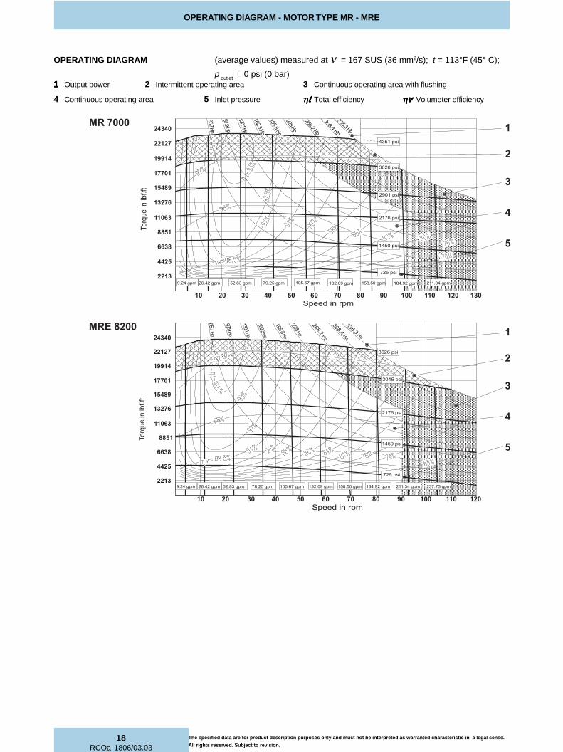
OPERATING DIAGRAM - MOTOR TYPE MR - MRE
11111 Output power 2 Intermittent operating area 3 Continuous operating area with flushing
4 Continuous operating area 5 Inlet pressure ηηηηηttttt Total efficiency ηηηηηvvvvv Volumeter efficiency
OPERATING DIAGRAM (average values) measured at ν = 167 SUS (36 mm2/s); t = 113°F (45° C);
p outlet = 0 psi (0 bar)
The specified data are for product description purposes only and must not be interpreted as warranted characteristic in a legal sense.
All rights reserved. Subject to revision.
�
�
�
�
�
�����
����
����
��� �
�
�� ����
�� ����
��� ����
������
��� ����
��� ����
��� ����
��������
��������
��������
��������
�������
��� ������� ������ �� ������ �� ������ �� ������ ��� ������ ��� ������ ��� ��������� ������
�� �� �� �� �� �� �� �� � ��� ��� ��� ���
�����
�����
� ��
�����
����
�����
�����
����
����
����
����
�������������� ����
��� ����
��������
�
�
�
�
�
������
����
����
��� �
�
�����������
�� ����
�� ����
��� ����
��� ����
��� ����
������
��� ����
��� ����
��� ����
��������
��������
�������
��������
��������
� ������ �� ������ �� ������ ��� �������� ������ ��� ��������� ��������� ��������� ������ ��� ������
�� �� �� �� �� �� �� � ��� ��� �����
����
����
����
����
�����
�����
����
�����
� ��
�����
�����

19
RCOa 1806/03.03
OPERATING DIAGRAM - MOTOR TYPE MR - MRE
OPERATING DIAGRAM (average values) measured at ν = 167 SUS (36 mm2/s); t = 113°F (45° C);
Min. required pressure difference ∆∆∆∆∆p with idling speed (shaft unloaded) p outlet = 0 psi (0 bar)
The specified data are for product description purposes only and must not be interpreted as warranted characteristic in a legal sense.
All rights reserved. Subject to revision.
MR - MRE350 - 800
MR - MRE1100 - 2100
MR33 - 110
MR - MRE125 - 330
���
���
����
���
����
��
������������������� �� � ��� ��� ��� ��� ��� ���
��
���
���
���
� �
���
���
"#��
���"#$��
���
"#�����
"#$��
���
"#����
�
�� ������ ��� ��������� ������ ������ ��� ���
���
���
����
���
����
��
�����������
���
��
� �
���
���
���
���
���
���
"#����"#����
"#$����
"#����
"#����"#$���
�
������ ��� ������ ������ ��� �������������
���
�����
����
���
����
���
��
���
���
� �
���
���
���
���
"#���"#����"#����
"#����
"#���
"#$��
��
"#����
��� ��� ������ ���� ���� ����
���
�����
����
���
����
�����������
��
���
���
���
���
���
� �
���"#����
"#���
"#���
"#���
"#���

20RCOa 1806/03.03
OPERATING DIAGRAM - MOTOR TYPE MR - MRE
The specified data are for product description purposes only and must not be interpreted as warranted characteristic in a legal sense.
All rights reserved. Subject to revision.
OPERATING DIAGRAM (average values) measured at ν = 167 SUS (36 mm2/s); t = 113°F (45° C);
Min. required pressure difference ∆∆∆∆∆p with idling speed (shaft unloaded) p outlet = 0 psi (0 bar)
Minimum boost pressure during pump operation
MR - MRE2400 - 8200
MR33 - 110
MR - MRE125 - 330
��� ��� ������ ���� ���� ���������������
"�
����
����
����
����
���
��
��
���
���
���
���
���
� �
���
���"#���
�
"#���
"#���
"#���
"#���
������ ��� ������ ��� ������ �� �������������
"�
����
����
����
����
���
��
���
��
���
� �
���
���
���
���
���
"#����
"#����
"#����
"#����
"#����
"#$��
��
"#����
������ ����������� ��������� ���
���
�����
����
���
����
�����������
���
��
���
���
���
���
� �
���
���
"#$�����"#��
���
"#�����
"#$
����
�
"#�����
"#�����
"#$�����
"#�����"#�����
21
RCOa 1806/03.03
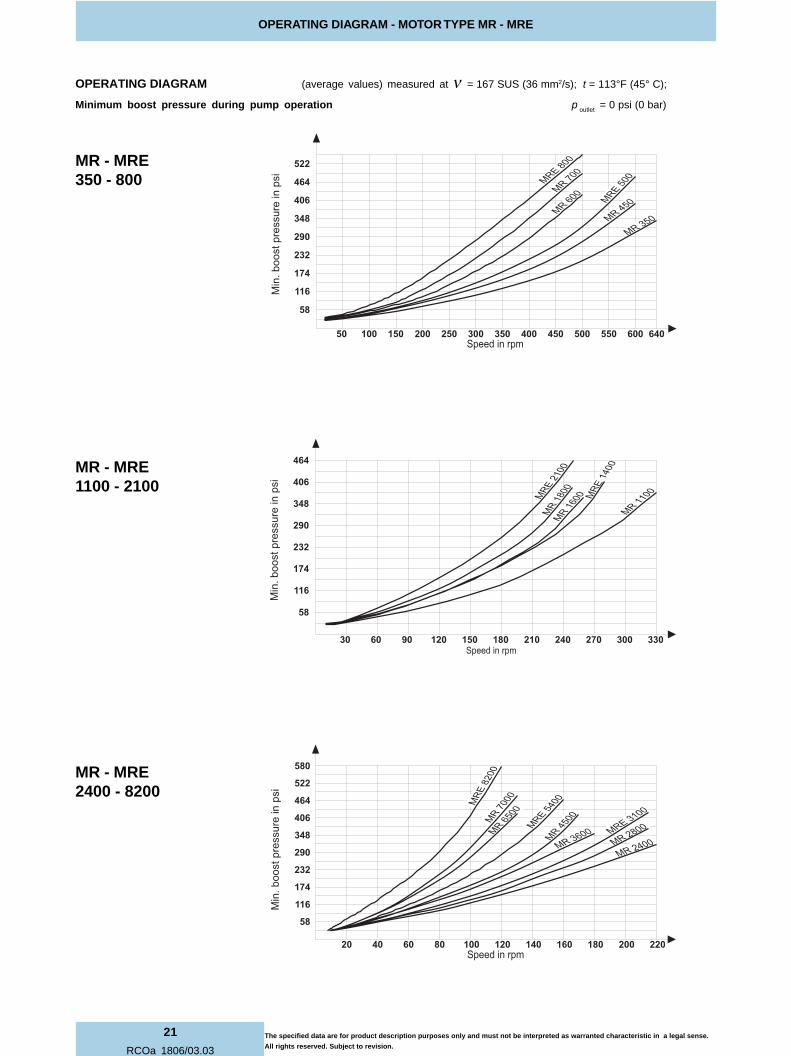
OPERATING DIAGRAM - MOTOR TYPE MR - MRE
OPERATING DIAGRAM (average values) measured at ν = 167 SUS (36 mm2/s); t = 113°F (45° C);
Minimum boost pressure during pump operation p outlet = 0 psi (0 bar)
The specified data are for product description purposes only and must not be interpreted as warranted characteristic in a legal sense.
All rights reserved. Subject to revision.
MR - MRE350 - 800
MR - MRE1100 - 2100
MR - MRE2400 - 8200
������ ��� ��� ��� ��� ������ ��� ��� ��� ����������������
"�
����
����
����
����
���
��
���
��
���
���
� �
���
���
���
���
"#����
"#$����
"#����
"#����"#����
"#$����
�� ��� ��� ��� ������ ��� ������ ��������������
"�
����
����
����
����
���
��
��
���
���
���
���
� �
���
���
"#$��
���
"#��
���
"#$
����
�
"#�����
"#��
���
����� ���� �� ��� ��� ��� ������ ��������������
"�
����
����
����
����
���
��
���
��
���
���
���
� �
���
���
���
���
"#
$���
��
"#�����
"#��
���
"#�����
"#$�����
"#�����
"#�����
"#�����"#$�����

22RCOa 1806/03.03
RADIAL LOAD - MOTOR TYPE MR - MRE
ROTOM ROTOM ROTOM ROTOM ROTOMEPYT
LAIDAR LAIDAR LAIDAR LAIDAR LAIDARECROF XAM XAM XAM XAM XAM IIIII
YLFEIRBHTIWDETTIMREP
DAOLCIMANYDfblniF 11111)))))
ERTNECTFAHSNIECROFLAIDARDETTIMREP.XAM ERTNECTFAHSNIECROFLAIDARDETTIMREP.XAM ERTNECTFAHSNIECROFLAIDARDETTIMREP.XAM ERTNECTFAHSNIECROFLAIDARDETTIMREP.XAM ERTNECTFAHSNIECROFLAIDARDETTIMREP.XAMLNODESAB 01H 01H 01H 01H 01H SRUOH0005 SRUOH0005 SRUOH0005 SRUOH0005 SRUOH0005
nideeps nideeps nideeps nideeps nideepsmprERUSSERPTUPNI ERUSSERPTUPNI ERUSSERPTUPNI ERUSSERPTUPNI ERUSSERPTUPNI
isp1092fblniF
ERUSSERPTUPNI ERUSSERPTUPNI ERUSSERPTUPNI ERUSSERPTUPNI ERUSSERPTUPNIisp6712
fblniF
ERUSSERPTUPNI ERUSSERPTUPNI ERUSSERPTUPNI ERUSSERPTUPNI ERUSSERPTUPNIisp0541
fblniF
33RM 33RM 33RM 33RM 33RM 73.1724 96.5312 50.3922 89.2832 004
75RM 75RM 75RM 75RM 75RM 73.1724 96.5312 50.3922 89.2832 004
37RM 37RM 37RM 37RM 37RM 02.8505 82.3202 87.7062 29.4303 053
39RM 39RM 39RM 39RM 39RM 02.8505 82.3202 87.7062 29.4303 053
011RM 011RM 011RM 011RM 011RM 02.8505 82.3202 87.7062 29.4303 053
521RM 521RM 521RM 521RM 521RM 02.8505 50.4211 16.5222 40.0092 572
061RM 061RM 061RM 061RM 061RM 02.8505 50.4211 16.5222 40.0092 572
091RM 091RM 091RM 091RM 091RM 02.8505 50.4211 16.5222 40.0092 572
*002RM *002RM *002RM *002RM *002RM - - - - -
052RM 052RM 052RM 052RM 052RM 56.4926 39.8521 16.5222 95.2382 052
003RM 003RM 003RM 003RM 003RM 56.4926 39.8521 16.5222 95.2382 052
053RM 053RM 053RM 053RM 053RM 13.8687 37.9523 94.6314 59.5674 522
054RM 054RM 054RM 054RM 054RM 13.8687 37.9523 94.6314 59.5674 522
006RM 006RM 006RM 006RM 006RM 87.6669 31.2733 02.8505 82.7316 002
007RM 007RM 007RM 007RM 007RM 87.6669 31.2733 02.8505 82.7316 002
0011RM 0011RM 0011RM 0011RM 0011RM 7.93121 79.8514 60.7046 82.3197 051
0061RM 0061RM 0061RM 0061RM 0061RM 78251 99.9885 42.7219 54.04211 521
0081RM 0081RM 0081RM 0081RM 0081RM 78251 99.9885 42.7219 54.04211 521
0042RM 0042RM 0042RM 0042RM 0042RM 67.80191 39.26211 93.73841 33.56271 011
0082RM 0082RM 0082RM 0082RM 0082RM 67.80191 86.93121 28.11551 38.94871 001
0063RM 0063RM 0063RM 0063RM 0063RM 73.97242 05.46321 8.23202 23.55132 001
0054RM 0054RM 0054RM 0054RM 0054RM 73.97242 1.53571 74.60812 71.40542 58
0056RM 0056RM 0056RM 0056RM 0056RM 4.42103 68.53661 5.15672 60.89613 05
0007RM 0007RM 0007RM 0007RM 0007RM 4.42103 68.53661 5.15672 60.89613 05
033ERM 033ERM 033ERM 033ERM 033ERM 56.4926 46.1101 88.0191 32.5762 052
005ERM 005ERM 005ERM 005ERM 005ERM 13.8687 36.7872 02.9883 30.6764 522
008ERM 008ERM 008ERM 008ERM 008ERM 87.6669 78.0191 22.1544 84.2195 002
0041ERM 0041ERM 0041ERM 0041ERM 0041ERM 7.93121 53.3391 24.5935 85.3557 041
0012ERM 0012ERM 0012ERM 0012ERM 0012ERM 78251 11.0182 02.3008 72.85801 021
0013ERM 0013ERM 0013ERM 0013ERM 0013ERM 67.80191 4.61101 81.00541 71.54471 001
0045ERM 0045ERM 0045ERM 0045ERM 0045ERM 73.97242 69.26141 77.77202 22142 08
0028ERM 0028ERM 0028ERM 0028ERM 0028ERM 4.42103 10.78251 89.82742 45.57782 05
11111 "1F"edocylno*002RM-detpeccaebnacseulavrehgih,noitidnoccimanydehthtiwecnadroccani) "1F"edocylno*002RM-detpeccaebnacseulavrehgih,noitidnoccimanydehthtiwecnadroccani) "1F"edocylno*002RM-detpeccaebnacseulavrehgih,noitidnoccimanydehthtiwecnadroccani) "1F"edocylno*002RM-detpeccaebnacseulavrehgih,noitidnoccimanydehthtiwecnadroccani) "1F"edocylno*002RM-detpeccaebnacseulavrehgih,noitidnoccimanydehthtiwecnadroccani)
RADIAL LOAD
The specified data are for product description purposes only and must not be interpreted as warranted characteristic in a legal sense.
All rights reserved. Subject to revision.

23
RCOa 1806/03.03
BEARING LIFE - MOTOR TYPE MR - MRE
L10h is the theoretically service life value normally reached or exceeded by the 90% of the bearings.
50 % of the bearings reach the value L50h = 5 times L 10h.
C p = Load coefficentK = Sevice life coefficent for standard bearingp = operating pressure in barConvert pressure 1psi = 0.0690 bar
EPYTROTOM EPYTROTOM EPYTROTOM EPYTROTOM EPYTROTOM KKKKK EPYTROTOM EPYTROTOM EPYTROTOM EPYTROTOM EPYTROTOM KKKKK EPYTROTOM EPYTROTOM EPYTROTOM EPYTROTOM EPYTROTOM KKKKK
33RM 33RM 33RM 33RM 33RM 0512 033ERM 033ERM 033ERM 033ERM 033ERM 058 0012ERM 0012ERM 0012ERM 0012ERM 0012ERM 227
75RM 75RM 75RM 75RM 75RM 0512 053RM 053RM 053RM 053RM 053RM 6211 0042RM 0042RM 0042RM 0042RM 0042RM 429
37RM 37RM 37RM 37RM 37RM 0231 054RM 054RM 054RM 054RM 054RM 6211 0082RM 0082RM 0082RM 0082RM 0082RM 429
39RM 39RM 39RM 39RM 39RM 0231 005ERM 005ERM 005ERM 005ERM 005ERM 1201 0013ERM 0013ERM 0013ERM 0013ERM 0013ERM 828
011RM 011RM 011RM 011RM 011RM 0231 006RM 006RM 006RM 006RM 006RM 029 0063RM 0063RM 0063RM 0063RM 0063RM 907
521RM 521RM 521RM 521RM 521RM 059 007RM 007RM 007RM 007RM 007RM 029 0054RM 0054RM 0054RM 0054RM 0054RM 907
061RM 061RM 061RM 061RM 061RM 059 008ERM 008ERM 008ERM 008ERM 008ERM 808 0045ERM 0045ERM 0045ERM 0045ERM 0045ERM 195
091RM 091RM 091RM 091RM 091RM 059 0011RM 0011RM 0011RM 0011RM 0011RM 448 0056RM 0056RM 0056RM 0056RM 0056RM 017
002RM 002RM 002RM 002RM 002RM 059 0041ERM 0041ERM 0041ERM 0041ERM 0041ERM 396 0007RM 0007RM 0007RM 0007RM 0007RM 017
052RM 052RM 052RM 052RM 052RM 059 0061RM 0061RM 0061RM 0061RM 0061RM 538 0028ERM 0028ERM 0028ERM 0028ERM 0028ERM 055
003RM 003RM 003RM 003RM 003RM 059 0081RM 0081RM 0081RM 0081RM 0081RM 538
BEARING LIFE
The specified data are for product description purposes only and must not be interpreted as warranted characteristic in a legal sense.
All rights reserved. Subject to revision.
Motor speed [rpm]
Load coefficent
L50h
L10h
(bar)

24RCOa 1806/03.03
MOTOR DIMENSIONS - MOTOR TYPE MR - MRE
1S
plin
ed s
haft
with
flan
k co
ntac
t (
for
dim
ensi
on s
ee p
age
26)
Ord
erin
g co
de "
N1"
(for
furt
her
shaf
t end
s se
e pa
ge 2
6 -
27)
2C
ase
drai
n po
rtB
SP
thre
ads
to IS
O 2
28/1
3O
n re
ques
t the
por
t fla
nge
can
bero
tate
d by
72°
(For
MR
33,
MR
57,
MR
73,
MR
93,
MR
110
, MR
125
, MR
160
, M
R 1
90,
MR
200
, MR
250
, MR
300
, MR
E 3
30,
MR
350
, MR
450
, MR
E 5
00, M
R 6
00,
MR
700
, MR
E 8
00ca
n be
rot
ated
by
36°)
For
sta
ndar
d po
sitio
n se
e an
ge α
.
4P
ort 1
/4“
BS
P th
read
s to
ISO
228
/1fo
r pr
essu
re r
eadi
ng.
L9
B2
B3
D6
A B
D7/
T1
D11
2
2
31
4
On
ly M
R 3
3, M
R 5
7(
SA
E S
tan
dar
d)
fo.ri
Dn
oitat
oR
no
de
weiV(
)d
ne
tfa
hs
tel
nitr
oP
ed
ocg
nire
dro
)5
3e
ga
pe
es(
esiwkc
olc
esiwkc
olc-itn
a
A B"
N"
esiwkc
olc
esiwkc
olc-itn
a
B A"
S"
The specified data are for product description purposes only and must not be interpreted as warranted characteristic in a legal sense.
All rights reserved. Subject to revision.

25
RCOa 1806/03.03
MOTOR DIMENSIONS - MOTOR TYPE MR - MRE
ROT
OM
ROT
OM
ROT
OM
ROT
OM
ROT
OM
EPYT1L1L 1L1L1L)ni(
2L2L 2L2L2L)ni(
3L3L 3L3L3L)ni(
4L4L 4L4L4L)ni(
5L5L 5L5L5L)ni(
6L6L 6L6L6L)ni(
7L7L 7L7L7L)ni(
8L8L 8L8L8L)ni(
9L9L 9L9L9L)ni(
01L01L01L01L01L)ni(
11L11L11L11L11L)ni(
21L21L21L21L21L)ni(
31L31L31L31L31L)ni(
1B
1B
1B
1B
1B
)ni(2
B2
B2
B2
B2
B)ni(
3B
3B
3B
3B
3B
)ni(4
B4
B4
B4
B4
B)ni(
ØØ ØØØ 1D
1D
1D
1D
1D
)ni(
ØØ ØØØ 2D
2D
2D
2D
2D
)ni(
ØØ ØØØ 3D
3D
3D
3D
3D
)ni(
ØØ ØØØ 4D
4D
4D
4D
4D
8h8h 8h8h8h** *** )ni(
ØØ ØØØ 5D
5D
5D
5D
5D
)ni(
ØØ ØØØ 6D
6D
6D
6D
6D
)ni(
7D
7D
7D
7D
7D
)m
m()
mm(
)m
m()
mm(
)m
m(1T1T 1T1T1T)ni(
8D
8D
8D
8D
8D
9D
9D
9D
9D
9D
)ni(
ØØ ØØØ01
D01
D01
D01
D01
D)ni(
ØØ ØØØ11
D11
D11
D11
D11
D)ni(
αα αααββ βββ
33R
M33
RM
33R
M33
RM
33R
M75
RM
79.927.7
38.512.4
52.255.0
57.067.2
60.243.4
90.367.2
87.088.4
65.230.1
37.272.9
3.690.7
2129.48819.4
)m
m521(
-27.4
01M
89.04/1
G53.0
28.389.0
°801°63
37R
M37
RM
37R
M37
RM
37R
M39
RM
011R
M96.11
00.905.7
81.507.2
76.097.0
31.243.1
27.407.3
48.2-
27.479.1
49.345.3
48.930.8
48.86807.52607.5
)m
m541(
-80.5
8M
95.08/3
G34.0
-97.0
°09°63
521R
M521
RM
521R
M521
RM
521R
M061
RM
091R
M71.21
35.930.8
17.546.2
55.036.0
31.243.1
18.560.4
48.262.0
27.479.1
49.349.3
33.2168.8
08.91992.67692.6
)m
m061(
-80.5
8M
95.08/3
G34.0
03.697.0
°09°63
002R
M002
RM
002R
M002
RM
002R
M052
RM
003R
M033
ER
M
27.2135.9
30.817.5
91.395.0
36.031.2
43.140.6
96.448.2
03.027.4
79.149.3
49.319.21
31.980.01
7988.63788.6
)m
m571(
45.380.5
8M
95.08/3
G34.0
83.697.0
°09°63
053R
M053
RM
053R
M053
RM
053R
M054
RM
005E
RM
8.4189.01
52.975.6
28.395.0
17.077.2
75.178.6
21.513.3
73.095.5
63.227.4
96.494.41
74.0156.11
2084.75774.7
)m
m091(
87.341.6
01M
17.08/3
G15.0
46.789.0
°09°63
006R
M006
RM
006R
M006
RM
006R
M007
RM
008E
RM
57.5177.11
40.0163.7
89.395.0
97.077.2
75.165.7
36.513.3
13.095.5
63.227.4
42.559.51
24.1106.21
4166.86856.8
)m
m022(
20.441.6
01M
17.08/3
G15.0
51.889.0
°09°63
0011R
M0011
RM
0011R
M0011
RM
0011R
M0041
ER
M30.81
34.3145.11
99.716.4
97.078.0
32.379.1
87.805.6
31.453.0
83.678.2
53.538.5
05.8199.21
54.415248.97938.9
)m
m052(
27.477.6
21M
38.02/1
G95.0
89.822.1
°401°63
0061R
M0061
RM
0061R
M0061
RM
0061R
M0081
RM
0012E
RM
29.9127.41
38.2192.9
02.538.0
49.032.3
79.193.01
67.731.4
34.083.6
78.253.5
16.679.12
69.4156.61
3714.111414.11
)m
m092(
38.577.6
21M
38.02/1
G76.0
74.0122.1
°09°63
0042R
M0042
RM
0042R
M0042
RM
0042R
M0082
RM
0013E
RM
73.4253.81
34.5122.11
20.649.0
20.168.3
44.239.11
07.848.4
95.091.8
93.390.7
84.782.52
23.7154.91
9881.314581.31
)m
m533(
15.564.8
41M
01.12/1
G57.0
63.2164.1
°09°63
0063R
M0063
RM
0063R
M0063
RM
0063R
M0054
RM
0045E
RM
45.7272.91
84.6111.21
72.843.1
01.168.3
86.251.41
27.915.5
57.060.9
75.478.7
54.961.03
62.1205.32
9747.517547.51
)m
m004(4
D*
7h
7h
7h
7h
7h
-64.8
61M
62.12/1
G19.0
69.4105.1
°801°63
0056R
M0056
RM
0056R
M0056
RM
0056R
M0007
RM
0028E
RM
43.1382.22
94.9121.51
60.964.1
81.168.3
86.240.61
27.915.5
38.060.9
75.478.7
93.0120.43
26.3239.52
5617.71417.71
)m
m054(4
D*
7h
7h
7h
7h
7h
84.764.8
61M
52.12/1
G89.0
27.7105.1
°801°63
The specified data are for product description purposes only and must not be interpreted as warranted characteristic in a legal sense.
All rights reserved. Subject to revision.
26RCOa 1806/03.03
SHAFT END DIMENSIONS - MOTOR TYPE MR - MRE
noi
sre
Vn
oisr
eV
noi
sre
Vn
oisr
eV
noi
sre
V1
N1
N1
N1
N1
N1
B1
B1
B1
B1
B1
D1
D1
D1
D1
D
ep
yT
ep
yT
ep
yT
ep
yT
ep
yT
5L
5L
5L
5L
5L
)ni(
12
L1
2L
12
L1
2L
12
L)
ni(2
2L
22
L2
2L
22
L2
2L
)ni(
21
D2
1D
21
D2
1D
21
D)
mm(
01
T0
1T
01
T0
1T
01
T)
ni(
31
DØ
31
DØ
31
DØ
31
DØ
31
DØ
36
45
NID
xe
)m
m(
5L
5L
5L
5L
5L
)ni(
12
L1
2L
12
L1
2L
12
L)
ni(2
2L
22
L2
2L
22
L2
2L
)ni(
21
D2
1D
21
D2
1D
21
D)
mm(
01
T0
1T
01
T0
1T
01
T)
ni(3
1D
Ø3
1D
Ø3
1D
Ø3
1D
Ø3
1D
Ø0
55
3S
B5
L5
L5
L5
L5
L)
ni(1
2L
12
L1
2L
12
L1
2L
)ni(
22
L2
2L
22
L2
2L
22
L)
ni(2
1D
21
D2
1D
21
D2
1D
)m
m(0
1T
01
T0
1T
01
T0
1T
)ni(
31
DØ
31
DØ
31
DØ
31
DØ
31
DØ
08
45
NID
)m
m(
33
RM
33
RM
33
RM
33
RM
33
RM
75
RM
42.
27
5.1
01.
1-
-2
3x
62
x6
B-
--
--
-4
2.2
75.
10
1.1
--
e8-
02
x5,
1x
23
W
37
RM
37
RM
37
RM
37
RM
37
RM
39
RM
01
1R
M0
7.2
30.
24
2.1
21
M-
43
x8
2x
6B
--
--
--
07.
23
0.2
42.
12
1M
-e
8-6
1x
2x
53
W
52
1R
M5
21
RM
52
1R
M5
21
RM
52
1R
M0
61
RM
09
1R
M4
6.2
79.
10
4.1
21
M9
7.0
83
x2
3x
8B
46.
27
9.1
04.
12
1M
97.
07
1-4
2/2
14
6.2
79.
10
4.1
21
M9
7.0
e8-
81
x2
x8
3W
*0
02
RM
*0
02
RM
*0
02
RM
*0
02
RM
*0
02
RM
--
--
--
--
--
--
--
--
--
05
2R
M0
52
RM
05
2R
M0
52
RM
05
2R
M0
03
RM
03
3E
RM
91.
36
3.2
18.
12
1M
89.
08
4x
24
x8
B9
1.3
63.
27
7.1
21
M8
9.0
12-
42/
21
91.
36
3.2
18.
12
1M
89.
0e
8-2
2x
2x
84
W
05
3R
M0
53
RM
05
3R
M0
53
RM
05
3R
M0
54
RM
00
5E
RM
28.
31
9.2
22.
22
1M
89.
04
5x
64
x8
B2
8.3
19.
20
4.2
21
M8
9.0
71-
61/
82
8.3
19.
26
3.2
21
M8
9.0
e8-
71
x3
x5
5W
00
6R
M0
06
RM
00
6R
M0
06
RM
00
6R
M0
07
RM
00
8E
RM
89.
37
0.3
44.
22
1M
89.
00
6x
25
x8
B8
9.3
70.
34
4.2
21
M8
9.0
71-
61/
88
9.3
70.
34
4.2
21
M8
9.0
e8-
81
x3
x0
6W
00
11
RM
00
11
RM
00
11
RM
00
11
RM
00
11
RM
00
41
ER
M1
6.4
64.
32
7.2
21
M8
9.0
27
x2
6x
8B
16.
46
4.3
46.
22
1M
89.
04
1-2
1/6
16.
46
4.3
38.
22
1M
89.
0e
8-2
2x
3x
07
W
00
61
RM
00
61
RM
00
61
RM
00
61
RM
00
61
RM
00
81
RM
00
12
ER
M0
2.5
49.
31
1.3
21
M8
9.0
28
x2
7x
01
B0
2.5
49.
39
9.2
21
M8
9.0
02-
21/
60
2.5
49.
35
1.3
21
M8
9.0
e8-
52
x3
x0
8W
00
42
RM
00
42
RM
00
42
RM
00
42
RM
00
42
RM
00
82
RM
00
13
ER
M2
0.6
27.
40
9.3
21
M8
9.0
29
x2
8x
01
B2
0.6
27.
49
9.2
21
M8
9.0
02-
21/
62
0.6
27.
44
9.3
21
M8
9.0
e8-
12
x4
x0
9W
00
63
RM
00
63
RM
00
63
RM
00
63
RM
00
63
RM
00
54
RM
00
45
ER
M7
2.8
18.
67
6.5
21
M8
9.0
21
1x
20
1x
01
B7
2.8
18.
61
6.5
21
M8
9.0
02-
21/
67
2.8
18.
67
6.5
21
M8
9.0
e8-
62
x4
x0
11
W
00
56
RM
00
56
RM
00
56
RM
00
56
RM
00
56
RM
00
07
RM
00
28
ER
M6
0.9
04.
71
9.5
21
M8
9.0
52
1x
21
1x
01
B6
0.9
04.
72
0.6
21
M8
9.0
62-
21/
66
0.9
04.
72
0.6
21
M8
9.0
e8-
82
x4
x0
21
W
eht
yb
deri
uq
ers
noi
sn
emi
ds
elo
he
hte
sa
cnI
.s
elo
he
civr
es
sa
der
edi
sn
oc
eb
ts
um
"1
D"d
na
"1
B","
1N"
sn
oisr
ev
tfa
hs
eht
rof
)0
1T/
21
D(s
elo
hd
ed
aer
hte
ht:
ET
ON
.in
ozl
aC
NO
SIN
ED
tc
atn
oc
es
elp
,e
vo
ba
ere
hd
etsil
se
no
eht
morf
tn
ereffi
der
an
oita
cilp
pa
"1
F"e
do
cyl
no
*0
02
RM
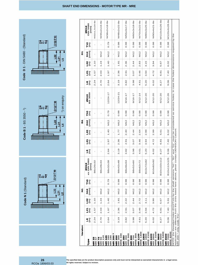
1 ) o
n en
quiry
Co
de
B 1
- B
S 3
550
- 1 )
Co
de
N 1
(S
tand
ard)
The specified data are for product description purposes only and must not be interpreted as warranted characteristic in a legal sense.
All rights reserved. Subject to revision.
Co
de
D 1
- D
IN 5
480
- (S
tand
ard)

27
RCOa 1806/03.03
SHAFT END DIMENSIONS - MOTOR TYPE MR - MRE
noi
sr
eV
noi
sr
eV
noi
sr
eV
noi
sr
eV
noi
sr
eV
FF FFFPP PPP
ep
yT
ep
yT
ep
yT
ep
yT
ep
yT
5L
5L
5L
5L
5L
)ni(
12
L1
2L
12
L1
2L
12
L)
ni(2
2L
22
L2
2L
22
L2
2L
)ni(
31
DØ
31
DØ
31
DØ
31
DØ
31
DØ
08
45
NID
)m
m(
5L
5L
5L
5L
5L
)ni(
12
L1
2L
12
L1
2L
12
L)
ni(6
2L
62
L6
2L
62
L6
2L
)ni(
21
D2
1D
21
D2
1D
21
D)
mm(
)m
m()
mm(
)m
m()
mm(
01
T0
1T
01
T0
1T
01
T)
ni(
41
DØ
41
DØ
41
DØ
41
DØ
41
DØ
6k
**
)ni(
)ni(
)ni(
)ni(
)ni(
)m
m(y
eK
)m
m(y
eK
)m
m(y
eK
)m
m(y
eK
)m
m(y
eK
Bx
L
detti
ms
na
rT
detti
ms
na
rT
detti
ms
na
rT
detti
ms
na
rT
detti
ms
na
rT
eu
qr
ot)tf.f
bl(
ET
ON
ET
ON
ET
ON
ET
ON
ET
ON
ote
uqr
ote
htf
os
eul
av
re
hgi
hr
oF
tlu
sn
oc
es
ael
p,
detti
ms
nart
eb
NO
SIN
ED
in
ozl
aC
33
RM
33
RM
33
RM
33
RM
33
RM
75
RM
76.
00
2.0
38.
0H
9-1
2x
52,
1x
82
N-
--
--
--
37
RM
37
RM
37
RM
37
RM
37
RM
39
RM
01
1R
M7
6.0
02.
02
0.1
H9-
41
x2
x2
3N
--
--
--
-
52
1R
M5
21
RM
52
1R
M5
21
RM
52
1R
M0
61
RM
09
1R
M5
5.0
02.
00
1.1
H9-
61
x2
x5
3N
46.
27
9.1
96.
12
1M
97.
05
57
5.1
94
75.
1)
mm
04(
21
x5
46
63
*0
02
RM
*0
02
RM
*0
02
RM
*0
02
RM
*0
02
RM
60.
10
2.0
24.
1H
9-8
1x
2x
04
N-
--
--
--
-
05
2R
M0
52
RM
05
2R
M0
52
RM
05
2R
M0
03
RM
03
3E
RM
60.
10
2.0
24.
1H
9-8
1x
2x
04
N9
1.3
63.
21
1.2
21
M8
9.0
29
69.
16
86
9.1
)m
m0
5(4
1x
65
26
6
05
3R
M0
53
RM
05
3R
M0
53
RM
05
3R
M0
54
RM
00
5E
RM
01.
10
2.0
05.
1H
9-2
2x
2x
74
N2
8.3
19.
22
3.2
21
M8
9.0
16
61.
25
56
1.2
)m
m5
5(6
1x
07
24
01
00
6R
M0
06
RM
00
6R
M0
06
RM
00
6R
M0
07
RM
00
8E
RM
01.
10
2.0
37.
1H
9-7
1x
3x
55
N8
9.3
70.
32
5.2
21
M8
9.0
03
63.
23
26
3.2
)m
m0
6(8
1x
07
89
41
00
11
RM
00
11
RM
00
11
RM
00
11
RM
00
11
RM
00
41
ER
M0
5.1
13.
07
9.1
H9-
02
x3
x5
6N
16.
46
4.3
10.
32
1M
89.
07
65
7.2
06
57.
2)
mm
07(
02
x0
84
89
1
00
61
RM
00
61
RM
00
61
RM
00
61
RM
00
61
RM
00
81
RM
00
12
ER
M5
8.1
13.
04
2.2
H9-
42
x3
x5
7N
02.
54
9.3
53.
32
1M
89.
04
05
1.3
79
41.
3)
mm
08(
22
x0
95
69
2
00
42
RM
00
42
RM
00
42
RM
00
42
RM
00
42
RM
00
82
RM
00
13
ER
M9
8.1
13.
04
4.2
H9-
72
x3
x5
8N
20.
62
7.4
47.
32
1M
89.
02
44
5.3
43
45.
3)
mm
09(
52
x0
11
87
54
00
63
RM
00
63
RM
00
63
RM
00
63
RM
00
63
RM
00
54
RM
00
45
ER
M7
9.1
55.
08
6.2
H9-
23
x3
x0
01
N7
2.8
18.
67
5.4
21
M8
9.0
61
33.
48
03
3.4
)m
m0
11(
82
x0
61
43
97
00
56
RM
00
56
RM
00
56
RM
00
56
RM
00
56
RM
00
07
RM
00
28
ER
M7
9.1
55.
09
9.2
H9-
53
x3
x0
11
N6
0.9
04.
73
4.5
**
*2
1M
89.
06
17
8.4
19
68.
4)
mm
42
1(2
3x
08
1-2
°N
05
80
2
era
noit
acil
pp
ae
hty
bd
eriu
qer
sn
ois
ne
mid
sel
oh
eht
es
ac
nI.
sel
oh
eci
vre
ss
ad
ere
dis
no
ce
bt
su
m"
1P
"s
noi
sre
vtf
ah
se
htr
of)
01
T/2
1D(
sel
oh
de
da
erht
eht
:E
TO
N.i
no
zla
CN
OSI
NE
Dt
cat
no
ce
sel
p,
ev
ob
aer
eh
det
sils
en
oe
htm
orft
ner
effid
"1
F"
ed
oc
yln
o*
00
2R
M
**
41
DØ
41
DØ
41
DØ
41
DØ
41
DØ
8b
00
28
ER
M,
00
07
RM
,0
05
6R
Mr
ofs
ye
ko
wts
ed
ulc
nin
ois
ne
mid
sih
T*
**
Co
de
P 1
Co
de
F 1
- D
IN 5
480
-
The specified data are for product description purposes only and must not be interpreted as warranted characteristic in a legal sense.
All rights reserved. Subject to revision.
Co
de
P 1
***
On
ly M
R 6
500,
MR
700
0,M
RE
820
0

28RCOa 1806/03.03
COMPONENTS FOR SPEED CONTROL - MOTOR TYPE MR - MRE
MECHANICALTACHOMETER DRIVE
TACHOGENERATORDRIVE
ENCODERDRIVE
encoder
encoder drive flangeprotection
(see page 26)
Female connector included in the supply
α = 126° for the motor types MR 33-57
α = 54° for the motor types MR 73-93-110-125- 160-190-200-250-300 MRE 330
α =45° for the other types
INCREMENTAL ENCODER
DIMENSIONS
3.66
2.40
197
2x M8x1.77 (2x M8x1.97)*
( ) * Motor MR 73-93-110-125-160-190-200-250-300 MRE 330( )** Motor MR 33-57
Code "C1" Code "T1" Code "Q1"
(1.06)**
2x M8x1.77 (2x M8x1.97)* 2x M8x1.77 (2x M8x1.97)*
1 (1.12)*0.59
0.35
(1.06)**1 (1.12)*0.28
0.29
0.190.190.190.31
0.981.10 0.29
(1.06)**1 (1.12)*
(2.44)** 2.38 (2.50)*
1.10
φφφφ φ2.5
173
- φφφφ φ2
.518
4
1.89
φφφφ φ 0.
7873
- φ
φ
φ
φ
φ
0.7
907
0.55
0.23
0.10
2 φφφφ φ 2.
5173
- φφφφ φ
2.5
184
1.89
φ φ φ φ φ 0.
8661
- φ
φ φ φ φ 0.
8669
0.23
0.10
2
φ φ φ φ φ 2.
5173
- φφφφ φ
2.5
184
1.89
φφφφ φ 0.
8661
- φφφφ φ
0.8
669
φφφφ φ 0.
3143
- φφφφ φ
0.3
149
Dimensions in inch (threaded holes in mm)
Dimensions in inch (in)
The specified data are for product description purposes only and must not be interpreted as warranted characteristic in a legal sense.
All rights reserved. Subject to revision.
α

29
RCOa 1806/03.03
COMPONENTS FOR SPEED CONTROL - MOTOR TYPE MR - MRE
Encoder type: ELCIS mod. 478
Supply voltage: 8 to 24 Vcc
Current consumption: 120 mA max
Current output: 10 mA max
Output signal: A phase- MONODIRECTIONALA and B phase BIDIRECTIONAL
Response frequency: 100 KHz max
Number of pulses: 500 (others on request - max 2540)
Slew speed: Always compatible with maximummotor speed
Operating temperature range: from 32 to 158 °F
Storage temperature range: from -22 to +185 °F
Ball bearing life: 1.5x10⁹ rpm
Weigth: 0,220 lb
Protection degree: IP 67 (with protection andconnector assembled)
Connectors:
MONODIRECTIONAL RSF3/0.5 M (Lumberg) maleRKT3-06/5m (Lumberg) female
BIDIRECTIONAL RSF4/0.5 M (Lumberg) maleRKT4-07/5m (Lumberg) female
Note: Female connectors cable length equal to 16.4 foot (ft).
INCREMENTAL ENCODER
TECHNICAL DATA
Monodirectional
4 3 3 4
1 1
4 3 3 4
1 1
1 1 1
4 4
1
4 4
3 3 3 3
2 2
Femaleconnector
Maleconnector
Maleconnector
INCREMENTAL ENCODER
CONNECTION DIAGRAMS
Bidirectional
2 2
Femaleconnector
noitcnufdnaseriwroloC noitcnufdnaseriwroloC noitcnufdnaseriwroloC noitcnufdnaseriwroloC noitcnufdnaseriwroloC
11111 nworB nworB nworB nworB nworB )cdV42ot8(ylppuSrewoP
22222 etihW etihW etihW etihW etihW )ccV42-Am01XAM(esahpBtuptuO
33333 eulB eulB eulB eulB eulB )cdV0(ylppuSrewoP
44444 kcalB kcalB kcalB kcalB kcalB )ccV42-Am01XAM(esahpAtuptuO
The specified data are for product description purposes only and must not be interpreted as warranted characteristic in a legal sense.
All rights reserved. Subject to revision.

30RCOa 1806/03.03
PIPE CONNECTION FLANGES - MOTOR TYPE MR - MRE
STANDARD CONNECTION FLANGECode “C1“
Flange is supplied complete with screws and seals.
SAE CONNECTION FLANGECodice “S1“Codice “T1“Codice “G1“Codice “L1“
Permitted up to 6000 PSI
RMRMRMRMRMERM
DDDDD)PSB(
HHHHH)hcni(
EDOC EDOC EDOC EDOC EDOCRBN
EDOC EDOC EDOC EDOC EDOCMPF
011-39-37 011-39-37 011-39-37 011-39-37 011-39-37091-061-521
052-002033-003
"4/3 24.1 890262 493922
054-053 054-053 054-053 054-053 054-053005
007-006008
"4/11 75.1 980262 593922
0041-0011 0041-0011 0041-0011 0041-0011 0041-00110081-0061
0012"2/11 77.1 390262 693922
0082-0042 0082-0042 0082-0042 0082-0042 0082-00420013
"2/11 63.2 275462 793922
0054-0063 0054-0063 0054-0063 0054-0063 0054-00630045
0007-00560028
"2 63.2 427272 893922
RMRMRMRMRMERM
EAS EAS EAS EAS EASISP
DDDDD
HHHHH)hcni(
IIIII)hcni(
XXXXX)hcni(
YYYYY)hcni(
CIRTEM CIRTEM CIRTEM CIRTEM CIRTEM CNU CNU CNU CNU CNU
""""")hcni( )hcni( )hcni( )hcni( )hcni( )mm(Z )mm(Z )mm(Z )mm(Z )mm(Z
)hcni(T
nosineD nosineD nosineD nosineD nosineDinozlaC°Ntrap
RBN
)"(Z )"(Z )"(Z )"(Z )"(Z-cni(T -cni(T -cni(T -cni(T -cni(T
)h
nosineD nosineD nosineD nosineD nosineDinozlaC°Ntrap
RBN
011-39-37 011-39-37 011-39-37 011-39-37 011-39-37091-061-521
052-002033-003
0005 "4/3847.0
)mm91(24.1 71.2 78.0 78.1 89.0/01M 592772 61-"8/3 489.0 533322
054-053 054-053 054-053 054-053 054-053005
007-006008
0005 "1489.0
)mm52(75.1 63.2 30.1 60.2 89.0/01M 792772 61-"8/3 489.0 633322
0041-0011 0041-0011 0041-0011 0041-0011 0041-00110061-0081
0012
0004 "4/11022.1
)mm13(77.1 59.2 91.1 13.2 89.0/01M 992772 41-61/7 81.1 733322
0006 "1489.0
)mm52(77.1 08.2 90.1 52.2 78.0/21M 661032 4161/7 81.1 290243
0082-0042 0082-0042 0082-0042 0082-0042 0082-00420013
0003 "2/11754.1
)mm73(63.2 93.3 14.1 57.2 81.1/21M 103772 31-"2/1 81.1 833322
0006 "2/11754.1
)mm73(63.2 48.3 44.1 31.3 81.1/61M 861032 11-"8/5 73.1 860943
0054-0063 0054-0063 0054-0063 0054-0063 0054-00630045
0007-00560028
0003 "2969.1
)mm05(63.2 14.4 96.1 60.3 81.1/21M 303772 31-"2/1 81.1 933322
0006 "2969.1
)mm05(63.2 75.4 57.1 18.3 83.1/02M 071032 01-"4/3 94.1 745243
Flange is supplied complete with screws and seals. FPM seals enquiry.
BSP threads to ISO 228/1
The specified data are for product description purposes only and must not be interpreted as warranted characteristic in a legal sense.
All rights reserved. Subject to revision.

31
RCOa 1806/03.03
COUPLINGS - KEY ADAPTERS - MOTOR TYPE MR - MRE
COUPLINGS
1 For standard male splined shaft version "N1" (see page 26).
22222
ADAPTERS WITH KEY
1 For standard male splined shaft version "N1" (see page 26).2 Key to DIN 6885
11111
11111
RMRMRMRMRMERM
GNIREDRO GNIREDRO GNIREDRO GNIREDRO GNIREDROEDOC
AAAAA)hcni(
BBBBB)hcni(
CCCCC 11H 11H 11H 11H 11H)hcni( )hcni( )hcni( )hcni( )hcni(
DDDDD)hcni(
EEEEE)hcni(
FFFFF)hcni(
GGGGG)hcni(
061-521 061-521 061-521 061-521 061-521091
302564 94.4 02.27145.14535.1)mm93(
58.1 31.2 16.0 63.1
003-052 003-052 003-052 003-052 003-052033
202564 13.5 08.24539.11929.1)mm94(
63.2 25.2 95.0 77.1
054-053 054-053 054-053 054-053 054-053005
102564 01.6 51.38271.23561.2
)mm55(86.2 86.2 37.0 91.2
007-006 007-006 007-006 007-006 007-006008
002564 37.6 45.30904.26104.2
)mm16(59.2 51.3 57.0 23.2
0011 0011 0011 0011 00110041
587464 23.7 71.44188.20478.2
)mm37(84.3 73.3 97.0 85.2
0081-0061 0081-0061 0081-0061 0081-0061 0081-00610012
991564 28.8 56.43672.37762.3
)mm38(68.3 12.4 78.0 70.3
0082-0042 0082-0042 0082-0042 0082-0042 0082-00420013
891564 34.01 02.50076.34166.3
)mm39(14.4 5 19.0 28.3
0054-0063 0054-0063 0054-0063 0054-0063 0054-00630045
296474 89.31 19.54754.48844.4
)mm311(69.4 05.6 81.1 15.5
0007-0056 0007-0056 0007-0056 0007-0056 0007-00560028
445224 53.51 86.74079.46069.4
)mm621(15.5 82.7 05.1 97.5
RMRMRMRMRMERM
GNIREDRO GNIREDRO GNIREDRO GNIREDRO GNIREDROEDOC
RRRRR3645NIDXE
)mm(
ddddd)hcni(
IIIII)hcni(
DDDDD 6k6k 6k 6k 6k)hcni( )hcni( )hcni( )hcni( )hcni(
LLLLL)hcni(
bbbbb)hcni(
ttttt)hcni(
)mm(yeK )mm(yeK )mm(yeK )mm(yeK )mm(yeK5886NID
061-521 061-521 061-521 061-521 061-521091
711172 83x23x8A 805.1 16.02482.25382.2
)mm85(79.1 93.0 04.2 54x8x01
003-052 003-052 003-052 003-052 003-052033
811172 84x24x8A 209.1 95.07657.20657.2
)mm07(63.2 55.0 98.2 65x9x41
054-053 054-053 054-053 054-053 054-053005
911172 45X64x8A 831.2 37.04051.37941.3
)mm08(59.2 36.0 13.3 07x01x61
007-006 007-006 007-006 007-006 007-006008
021172 06x25x8A 473.2 57.02445.34345.3
)mm09(51.3 170 07.3 07x11x81
0041-0011 0041-0011 0041-0011 0041-0011 0041-0011 121172 27x26x8A 648.2 97.08431.40431.4
)mm501(45.3 97.0 113.4 09x21x02
0081-0061 0081-0061 0081-0061 0081-0061 0081-00610012
221172 28x27x01A 42.3 78.06646.47546.4
)mm811(56.4 78.0 48.4 011x41x22
0082-0042 0082-0042 0082-0042 0082-0042 0082-00420013
321172 29x28x01A 436.3 19.01911.52811.5
)mm031(38.5 89.0 23.5 041x41x52
0054-0063 0054-0063 0054-0063 0054-0063 0054-00630045
917272 211x201x01A 124.4 81.12003.63992.6
)mm061(04.7 01.1 45.6 081x61x82
0007-0056 0007-0056 0007-0056 0007-0056 0007-00560028
674322 521x211x01A 449.4 05.17482.76382.7
)mm581(04.7 77.1 86.7 081x52x54
The specified data are for product description purposes only and must not be interpreted as warranted characteristic in a legal sense.
All rights reserved. Subject to revision.

32RCOa 1806/03.03
HOLDING BRAKE UNIT DIMENSIONS - MOTOR TYPE MR - MRE
EPYTEKARB EPYTEKARB EPYTEKARB EPYTEKARB EPYTEKARB1L1L1L1L1L
)hcni(2L2L2L2L2L
)hcni(3L3L3L3L3L
)hcni(4L4L4L4L4L
)hcni(5L5L5L5L5L
)hcni(6L6L6L6L6L
)hcni(7L7L7L7L7L
)hcni(01L 01L 01L 01L 01L
)hcni(11L 11L 11L 11L 11L
)hcni(12L 12L 12L 12L 12L
)hcni(22L 22L 22L 22L 22L
)hcni(1D1D1D1D1D
)mm(2D2D2D2D2D
)hcni(3D3D3D3D3D
)hcni(4D4D4D4D4D 8h 8h 8h 8h 8h
)hcni( )hcni( )hcni( )hcni( )hcni(5D5D5D5D5D
)hcni(6D6D6D6D6D
)PSB(7D7D7D7D7D
)PSB(9D9D9D9D9D
)hcni(21D 21D 21D 21D 21D
)hcni(31D 31D 31D 31D 31D)mm(
01T 01T 01T 01T 01T)hcni( ααααα11111 ααααα22222
091B 67.4 - 78.0 55.0 46.2 16.1 51.1 97.0 48.2 79.1 04.1H9-81x2x83N
0845NID48.9 68.8
1992.67692.6
)mm061(- "4/1 '8/3 14.0 21M
83x23x8B3645NIDxe
01.1 '03°22 '03°22
003B 53.5 - 89.0 95.0 91.3 56.1 65.1 38.0 93.3 63.2 18.1H9-22x2x84N
0845NID80.01 31.9
7988.62788.6
)mm571(- "4/1 '8/3 14.0 21M
84x24x8B3645NIDxe
01.1 '03°22 '03°22
054B 97.5 - 60.1 95.0 28.3 59.1 24.1 59.0 49.3 19.2 22.2H9-71x3x55N
0845NID56.11 74.01
2084.74774.7
)mm091(- "4/1 '8/3 35.0 21M
45x64x8B3645NIDxe
01.1 '03°22 '03°22
007B 77.6 - 01.1 95.0 89.3 71.2 18.1 89.0 31.4 70.3 44.2H9-81x3x06N
0845NID06.21 24.11
3166.85856.8
)mm022(- "4/1 '8/3 35.0 21M
06x25x8B3645NIDxe
01.1 '03°22 '03°22
0011B 04.7 97.0 20.1 59.0 16.4 08.2 11.2 98.1 27.4 74.3 48.2H9-22x3x07N
0845NID71.41 99.21
4248.96938.9
)mm052(27.4 "4/1
-x61M5,1
95.0 21M27x26x8B3645NIDxe
01.1 °0 °0
0081B 05.8 - 01.1 38.0 02.5 05.2 03.2 43.1 23.5 49.3 11.3H9-52x3x08N
0845NID56.61 69.41
2714.111414.11)mm092(
- "4/1 '2/1 96.0 21M28x27x01B3645NIDxe
01.1 '03°22 '03°22
0082B 53.01 - 81.1 59.0 20.6 34.3 46.2 76.1 05.6 27.4 09.3H9-12x4x09N
0845NID54.91 23.71
9881.314581.31)mm533(
- "4/1 '2 57.0 21M29x28x01B3645NIDxe
01.1 '03°22 '03°22
EPYTEKARB EPYTEKARB EPYTEKARB EPYTEKARB EPYTEKARB 091B 091B 091B 091B 091B 003B 003B 003B 003B 003B 054B 054B 054B 054B 054B 007B 007B 007B 007B 007B 0011B 0011B 0011B 0011B 0011B 0081B 0081B 0081B 0081B 0081B 0082B 0082B 0082B 0082B 0082B
EPYTROTOM EPYTROTOM EPYTROTOM EPYTROTOM EPYTROTOMERM-RM
061-521 061-521 061-521 061-521 061-521091
003-052 003-052 003-052 003-052 003-052033
054-053 054-053 054-053 054-053 054-053005
007-006 007-006 007-006 007-006 007-006008
0041-0011 0041-0011 0041-0011 0041-0011 0041-0011 0081-0061 0081-0061 0081-0061 0081-0061 0081-00610012
0082-0042 0082-0042 0082-0042 0082-0042 0082-00420013
The specified data are for product description purposes only and must not be interpreted as warranted characteristic in a legal sense.
All rights reserved. Subject to revision.
Same dimensionsstandard male splinedshaft version "N1"(see page 26)
ααααα1, ααααα2 Corresponding angles to the release ports 1 and 2, to case the drain ports 1 and 2
Release portsCase drain ports
Release portsCase drain ports
Case drain portsRelease ports
ø D
2
D7
L1
L11
D1
L10
L6D6
L7
L5L4
ø D
4 h
8
ø D
9
N°
5 H
OL
ES
L2L3
ø D
5
D12
T10
L21L22
ø D
3
ø D
13

33
RCOa 1806/03.03
HOLDING BRAKE TECHNICAL DATA - MOTOR TYPE MR - MRE
SCITSIRETCARAHC SCITSIRETCARAHC SCITSIRETCARAHC SCITSIRETCARAHC SCITSIRETCARAHCEPYTEKARB EPYTEKARB EPYTEKARB EPYTEKARB EPYTEKARB
091B 091B 091B 091B 091B 003B 003B 003B 003B 003B 054B 054B 054B 054B 054B 007B 007B 007B 007B 007B 0011B 0011B 0011B 0011B 0011B 0081B 0081B 0081B 0081B 0081B 0082B 0082B 0082B 0082B 0082B
EUQROTGNIKARBCITATS EUQROTGNIKARBCITATS EUQROTGNIKARBCITATS EUQROTGNIKARBCITATS EUQROTGNIKARBCITATS tf.fbl tf.fbl tf.fbl tf.fbl tf.fbl 229 8231 5591 0592 3754 8048 21621
EUQROTGNIKARBCIMANYD EUQROTGNIKARBCIMANYD EUQROTGNIKARBCIMANYD EUQROTGNIKARBCIMANYD EUQROTGNIKARBCIMANYD tf.fbl tf.fbl tf.fbl tf.fbl tf.fbl 246 588 9601 3261 8903 0164 1588
ERUSSERPESAELER ERUSSERPESAELER ERUSSERPESAELER ERUSSERPESAELER ERUSSERPESAELER isp isp isp isp isp 604 604 293 293 293 534 534
ERUSSERPGNITAREPO.XAM ERUSSERPGNITAREPO.XAM ERUSSERPGNITAREPO.XAM ERUSSERPGNITAREPO.XAM ERUSSERPGNITAREPO.XAM isp isp isp isp isp 2906 2906 2906 2906 2906 2906 2906
STRAPGNITATORFOAITRENIFOTNEMOM STRAPGNITATORFOAITRENIFOTNEMOM STRAPGNITATORFOAITRENIFOTNEMOM STRAPGNITATORFOAITRENIFOTNEMOM STRAPGNITATORFOAITRENIFOTNEMOM tf.fbl tf.fbl tf.fbl tf.fbl tf.fbl 22222 211.0 741.0 886.0 020.1 844.1 647.4 704.6
THGIEW THGIEW THGIEW THGIEW THGIEW blblblblbl 5.07 68 911 361 5,022 5.843 5.775
ERMRMEPYTROTOM ERMRMEPYTROTOM ERMRMEPYTROTOM ERMRMEPYTROTOM ERMRMEPYTROTOM521061091
052003033
053054005
006007008
00110041
006100810012
004200820013
TECHNICAL DATA (For operation outside these parameters, please consult DENISON Calzoni)
CODE Example: BRAKE - B 450 - N1 V1 **
091B 091B 091B 091B 091B "C"ezisrotomrofekarB
003B 003B 003B 003B 003B "D"ezisrotomrofekarB
054B 054B 054B 054B 054B "E"ezisrotomrofekarB
007B 007B 007B 007B 007B "F"ezisrotomrofekarB
0011B 0011B 0011B 0011B 0011B "G"ezisrotomrofekarB
0081B 0081B 0081B 0081B 0081B "H"ezisrotomrofekarB
0082B 0082B 0082B 0082B 0082B "I"ezisrotomrofekarB
1. BRAKE - B 450 NI V1 **
********** inozlaCnosineDotdevreserecapS
1N1N1N1N1N liolarenim:RBN
*1V *1V *1V *1V *1V slaesMPF
1U1U1U1U1U )ekarbrof(laestfahsoN
inozlaCNOSINEDtcatnocesaelp* inozlaCNOSINEDtcatnocesaelp* inozlaCNOSINEDtcatnocesaelp* inozlaCNOSINEDtcatnocesaelp* inozlaCNOSINEDtcatnocesaelp*
3. BRAKE - B 450 - N1 V1 **
1N1N1N1N1N )62egapees(3645NIDxeenilpS
*1D *1D *1D *1D *1D )62egapees(0845NIDenilpS
*1F *1F *1F *1F *1F )72egapees(0845NIDenilpselameF
inozlaCNOSINEDtcatnocesaelp* inozlaCNOSINEDtcatnocesaelp* inozlaCNOSINEDtcatnocesaelp* inozlaCNOSINEDtcatnocesaelp* inozlaCNOSINEDtcatnocesaelp*
2. BRAKE - B 450 - N1 V1 **
4. BRAKE - B 450 - N1 V1 **
BRAKE TYPE
SHAFT
SEALS
SPECIAL
The specified data are for product description purposes only and must not be interpreted as warranted characteristic in a legal sense.
All rights reserved. Subject to revision.
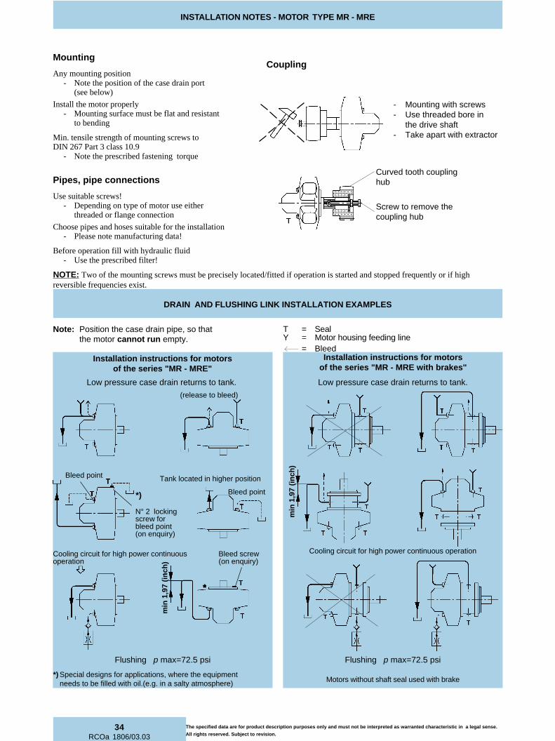
34RCOa 1806/03.03
INSTALLATION NOTES - MOTOR TYPE MR - MRE
Mounting
Any mounting position- Note the position of the case drain port
(see below)
Install the motor properly- Mounting surface must be flat and resistant
to bending
Min. tensile strength of mounting screws toDIN 267 Part 3 class 10.9
- Note the prescribed fastening torque
Pipes, pipe connections
Use suitable screws!- Depending on type of motor use either
threaded or flange connection
Choose pipes and hoses suitable for the installation- Please note manufacturing data!
Before operation fill with hydraulic fluid- Use the prescribed filter!
Coupling
- Mounting with screws- Use threaded bore in
the drive shaft- Take apart with extractor
NOTE: Two of the mounting screws must be precisely located/fitted if operation is started and stopped frequently or if highreversible frequencies exist.
Note: Position the case drain pipe, so thatthe motor cannot run empty.
T = SealY = Motor housing feeding line
= Bleed
Curved tooth couplinghub
Screw to remove thecoupling hub
*****
*)
Bleed point
(release to bleed)
Low pressure case drain returns to tank. Low pressure case drain returns to tank.
Motors without shaft seal used with brake
Tank located in higher position
N° 2 lockingscrew forbleed point(on enquiry)
*) Special designs for applications, where the equipmentneeds to be filled with oil.(e.g. in a salty atmosphere)
DRAIN AND FLUSHING LINK INSTALLATION EXAMPLES
Flushing p max=72.5 psi Flushing p max=72.5 psi
Cooling circuit for high power continuousoperation
Bleed screw(on enquiry)
Installation instructions for motorsof the series "MR - MRE"
Installation instructions for motorsof the series "MR - MRE with brakes"
Bleed point
Cooling circuit for high power continuous operation
The specified data are for product description purposes only and must not be interpreted as warranted characteristic in a legal sense.
All rights reserved. Subject to revision.
min
1,9
7 (i
nch
)
min
1,9
7 (i
nch
)

35
RCOa 1806/03.03
ORDERING CODE - MOTOR TYPE MR - MRE
CODE Example: MR 160C - N1 M1 F1 N1 N **
RMRMRMRMRM suounitnoc.xamisp6263dradnats
ERM ERM ERM ERM ERM suounitnoc.xamisp6403dednapxe
1. MR 160C - N1 M1 F1 N1 N **
AAAAAedoc A33RM A33RM A33RM A33RM A33RM A75RM A75RM A75RM A75RM A75RM
ni 3 69.1 44.3
BBBBBedoc B37RM B37RM B37RM B37RM B37RM B39RM B39RM B39RM B39RM B39RM B011RM B011RM B011RM B011RM B011RM
ni 3 34.4 56.5 56.6
CCCCCedoc C521RM C521RM C521RM C521RM C521RM C061RM C061RM C061RM C061RM C061RM C091RM C091RM C091RM C091RM C091RM
ni 3 16.7 57.9 96.11
DDDDDedoc D002RM D002RM D002RM D002RM D002RM D052RM D052RM D052RM D052RM D052RM D003RM D003RM D003RM D003RM D003RM D033ERM D033ERM D033ERM D033ERM D033ERM
ni 3 61.21 13.51 65.81 82.02
EEEEEedoc E053RM E053RM E053RM E053RM E053RM E054RM E054RM E054RM E054RM E054RM E005ERM E005ERM E005ERM E005ERM E005ERM
ni 3 33.12 65.72 83.03
FFFFFedoc F006RM F006RM F006RM F006RM F006RM F007RM F007RM F007RM F007RM F007RM F008ERM F008ERM F008ERM F008ERM F008ERM
ni 3 01.73 90.34 80.94
GGGGGedoc G0011RM G0011RM G0011RM G0011RM G0011RM G0041ERM G0041ERM G0041ERM G0041ERM G0041ERM
ni 3 7.86 6.38
HHHHHedoc H0061RM H0061RM H0061RM H0061RM H0061RM H0081RM H0081RM H0081RM H0081RM H0081RM H0012ERM H0012ERM H0012ERM H0012ERM H0012ERM
ni 3 5.79 4.011 6.721
IIIIIedoc I0042RM I0042RM I0042RM I0042RM I0042RM I0082RM I0082RM I0082RM I0082RM I0082RM I0013ERM I0013ERM I0013ERM I0013ERM I0013ERM
ni 3 9.931 4.071 4.981
LLLLLedoc L0063RM L0063RM L0063RM L0063RM L0063RM L0054RM L0054RM L0054RM L0054RM L0054RM L0045ERM L0045ERM L0045ERM L0045ERM L0045ERM
ni 3 9.122 8.472 6.923
MMMMMedoc M0056RM M0056RM M0056RM M0056RM M0056RM M0007RM M0007RM M0007RM M0007RM M0007RM M0028ERM M0028ERM M0028ERM M0028ERM M0028ERM
ni 3 2.493 7.804 205
2. MR 160C - N1 M1 F1 N1 N **
1N1N1N1N1N )62egapees(3645NIDxeenilps
1D1D1D1D1D )62egapees(0845NIDenilps
1F1F1F1F1F )72egapees(0845NIDenilpselamef
1P1P1P1P1P )72egapees(yekhtiwtfahs
1B1B1B1B1B )62egapees(0553.S.Benilps
3. MR 160C - N1 M1 F1 N1 N **
1N1N1N1N1N enon
1Q1Q1Q1Q1Q )82egapees(evirdredocne
1C1C1C1C1C )82egapees(evirdretemohcatlacinahcem
1T1T1T1T1T )82egapees(evirdrotarenegohcat
1M1M1M1M1M redocnesiclElatnemercni)82egapees()ver/eslup005(
lanoitcerid-inU
1B1B1B1B1B lanoitcerid-iB
4. MR 160C - N1 M1 F1 N1 N **
1N1N1N1N1N liolarenimRBN
1F1F1F1F1F laestfahsisp812,RBN
1V1V1V1V1V slaesMPF
1U1U1U1U1U )ekarbrof(laestfahson
5. MR 160C - N1 M1 F1 N1 N **
NNNNN )Bnitelni:WCC,Anitelni:WC(noitatordradnats
SSSSS )Anitelni:WCC,Bnitelni:WC(noitatordesrever
7. MR 160C - N1 M1 F1 N1 N **
1N1N1N1N1N enon
1C1C1C1C1C )03egapees(inozlaCNOSINEDdradnats
1S1S1S1S1S )03egapees(cirtemEASdradnats
1T1T1T1T1T )03egapees(CNUEASdradnats
1G1G1G1G1G )03egapees(cirtemisp0006EAS
1L1L1L1L1L )03egapees(CNUisp0006EAS
6. MR 160C - N1 M1 F1 N1 N **
********** inozlaCnosineDotdevreserecaps8. MR 160C - N1 M1 F1 N1 N **
SERIES
SIZE & DISPLACEMENT
SHAFT
SPEED SENSOR OPTION
SEALS
CONNECTION FLANGE
ROTATION
SPECIAL
The specified data are for product description purposes only and must not be interpreted as warranted characteristic in a legal sense.
All rights reserved. Subject to revision.

1RCOa 2401/01.02
The specified data are for product description purposes only and must not be interpreted as warranted characteristic in a legal sense. All
rights reserved. Subject to revision.
SALES AND SERVICE LOCATIONS WORLDWIDE
International Distributors
In Europe :CyprusCzech RepublicGreeceHungaryIcelandJugosaviaNorwayPortugalPolandRomaniaRussiaSlovakiaSloveniaSwitzerlandThe Faroe IslandsTurkey
In Africa :AlgeriaEgyptIvory CoastMoroccoNigeriaSouth AfricaTunisia
In Middle East :BahreinIranIsraelJordanKuwaitLebanonPakistanQatarSaudi ArabiaSyriaUnited Arab Emirates
In Far East :IndonesiaKoreaMalaysiaNew ZealandPhilippinesThailand
South-America :ArgentinaBrazilChileColombiaEcuadorMexicoPeruVenezuela
Denison Calzoni S.p.a.Via Caduti di Sabbiuno 15/1740011 Anzola dell’EmiliaBologna ItalyTel: +39 (051) 6501611Fax: +39 (051) 736221e-mail: [email protected]
Asia-Pacific
Australia
Denison Hydraulics PTY41-43 St Hilliers RoadP.O.Box 192Auburn N.S.W. 2144, AustraliaTel : +61 (2) 9646 5200Fax : +61 (2) 9643 1305
Hong Kong
Denison Hydraulics Ltd.Unit 6A, 33/F Cable TV Tower9 Hoi Shing Road, Tsuen WanNT, Hong KongTel : +852 2498 8381Fax : +852 2499 1522
Japan
Denison Japan Inc.4-2-1 Tsujido-ShinmachiFujisawa 251, JapanTel : +81 (466) 35-3050Fax : +81 (466) 35-2019
China
Denison Hydraulics Engineering Ltd.Room 8018, No. 601, Zhang YangRoad Pudong New AreaShanghai 200120, ChinaTel : +86 (21) 58205042 / 58205034Fax : +86 (21) 58205014
Singapore
Denison Hydraulics Sea Pte LTDBlk 5#06-12Ang Mo Kio Industrial Park 2ASingapore 567760Tel : +65 6268 7840Fax : +65 6268 7847
Taiwan
Denison Hydraulics LTD6F-10. No. 79,Sec. 2Roosevelt Road, TaipeiTel : +65 268 7840Fax : +65 268 7847
Europe
Austria
Denison Hydraulics GmbHZweigneiderlassung LinzHaibachstraße 694061 Pasching, AustriaTel : +43 (72 29) 48 87Fax : +43 (72 29) 6 30 92
Benelux
Denison Hydraulics Benelux B.V.Pascalstraat 1003316 GR Dordrecht, HollandTel : +31 (78) 6179 900Fax : +31 (78) 6175 755
Denmark
Denison Hydraulics Denmark A/SIndustrikrogen 22635 Ishöj, DenmarkTel : +45 (4371) 15 00Fax : +45 (4371) 15 16
Finland
Denison Lokomec OYPolunmäenkatu 22P.O.Box 11633721 Tampere, FinlandTel : + 358 (3) 3575 100Fax : + 358 (3) 3575 111
France
Denison Hydraulics France S.A.14 route du bois blancBP 53918105 Vierzon, Cedex, FranceTel : +33 (2) 48 53 01 20Fax : +33 (2) 48 75 02 91
Great Britain
Denison Hydraulics UK LTDKenmore roadWakefield 41, Industrial ParkWakefield, WF2 OXEWest Yokshire, EnglandTel : +44 (1924) 826 021Fax : +44 (1924) 826 146
Germany
Denison Hydraulik GmbH.Auf dem Sand 14D-40721 Hilden, GermanyTel : +49 (2103) 940 300Fax : +49 (2103) 940 558
Italy
Denison Hydraulics Italy SrlViale Europa 6820090 Cusago (MI), ItalyTel : +39 (02) 90330-1Fax : +39 (02) 90390694/5/6
Denison Calzoni S.p.AVia Caduti di Sabbiuno15/1740011 Anzola dell'EmiliaBologna, ItalyTel : +39 (051) 6501611Fax : +39 (051) 736221
Spain
Denison Hydraulics S.A.Poligono “La Post”C/ Enginy n°.6, Nave 808850 Gava, Barcelona, SpainTel : +34 (93) 635 5170Fax : +34 (93) 635 5178
Sweden
Denison Hydraulics Svenska ABSporregatan 13213 77 - Malmö, SwedenTel : +46 (40) 600 13 00Fax : +46 (40) 600 13 50
North America
Canada
Denison Hydraulics Canada Inc.2880 Brighton Road, Unit 1Oakville, ON L6H 5S3, CanadaTel : +1 (905) 829 5800Fax : +1 (905) 829 5805
Mexico, Central America,South America, Caribbeancountries
Denison Hydraulics Corp.6167 NW 181 Terrace CircleNorthMiami, FL 33015, USATel : +1 (305) 362 2246Fax : +1 (305) 362 2246
USA
Denison Hydraulics Inc.14249 Industrial ParkwayMarysville, OH 43040-9551,USATel : +1 (937) 644 3915Fax : +1 (937) 642 3738
Others
Other European, Middle East,African countries
Denison Hydraulics France S.A.14 route du bois blancBP 53918105 Vierzon, FranceTel : +33 (2) 48 53 01 20Fax : +33 (2) 48 53 01 46
Your local Denison Hydraulics representative


