Demonstrations for the Materials Science Classroom final
41
Demonstrations for the Materials Science Classroom Organized and Assembled By: Silas Brown Starr’s Mill High School [email protected] for Dr. Jud Ready Georgia Institute of Technology Copyright 2006
Transcript of Demonstrations for the Materials Science Classroom final

Demonstrations for the Materials Science Classroom
Organized and Assembled By:
Silas Brown Starr’s Mill High School [email protected]
for
Dr. Jud Ready Georgia Institute of Technology
Copyright 2006
NHealy
Text Box
NNIN Nanotechnology Education
NHealy
Typewritten Text
2
Table of Contents
Materials Science Resource Kit ...........................................................................................................3
Compartment A ................................................................................................................................4 Compartment B ................................................................................................................................4 Compartment C ................................................................................................................................5 Compartments D-K ..........................................................................................................................5 Hardware Store Shopping List .........................................................................................................7 Walmart Shopping List ....................................................................................................................7 Specialty Items: ................................................................................................................................7 Materials you should have or can get your hands on: ......................................................................8
Demonstrations and Examples .............................................................................................................9 1. Material Science Intro ..................................................................................................................9 2. Classifying Materials..................................................................................................................10 3. Ball Point Pen.............................................................................................................................11 4. Point Defect Board .....................................................................................................................13 5. Cry of Tin ...................................................................................................................................14 6. Surface Tension Demo of Water ................................................................................................15 7. Glass Fibers ................................................................................................................................16 8. Laboratory Experiments From the Toy Store ............................................................................17 9. Rubber Band Stress-Strain Curve ..............................................................................................18 10. Solubility and Immiscibility...................................................................................................19 11. Heat Treating Piano Wire.......................................................................................................20 12. Heat Treating Nails ................................................................................................................22 13. Water Absorbing Polymer......................................................................................................25 14. Buckling Breakdown..............................................................................................................26 15. Glass .......................................................................................................................................27 16. Fatigue Demo .........................................................................................................................28 17. Memory Metal........................................................................................................................31 18. Work Hardening.....................................................................................................................32 19. Tempered Steel.......................................................................................................................33 20. A Demonstration of Chill Block Melt Spinning of Metal......................................................34 21. Temperature Dependent Electrical Conductivity of Soda-Lime Glass ..................................36 22. Superconductivity Experiment ...............................................................................................39 23. Index of Refraction Demo......................................................................................................40 24. Karo Syrup Experiment..........................................................................................................41 25. Permanent Magnets ................................................................................................................42 26. Thermal Insulation .................................................................................................................43 27. Thermal Shock Demo.............................................................................................................44 28. Corrosion and Passivation......................................................................................................45 29. More Surface = Faster Reaction.............................................................................................46

3
Materials Science Resource Kit
A
C
D
B
E
K
J
G
F
H
I
4
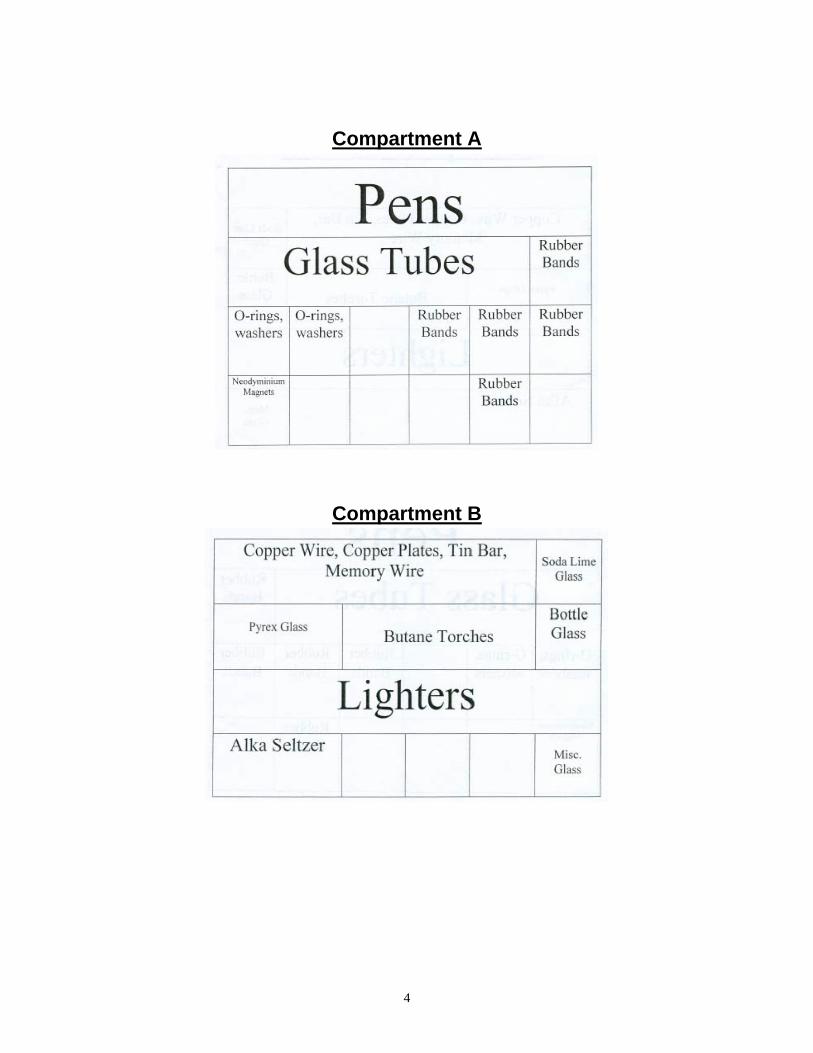
Compartment A
Compartment B

5
Compartment C
Compartments D-K
D C-Clamp
Empty Film Canisters Hammer
Tin Solder
E Agrosoke
Butane Refill Extension Cord
F Superconductivity Kit
Thermal Insulation
G Light Bulbs Racquetballs
H 9” Aluminum Pan
Copper Tubing Electrical Conductivity Device
Play-Doh Fun Factory PVC Tubing
Steel Rods
I Regular panes of glass
Tempered Pane of Glass Various Metal Plates (copper, stainless steel,
aluminum, etc..)
J Beach balls
K Butane Refill
Guitar Stri

6
This shopping list is provided in case you would like to reproduce this Materials Science Kit in its entirety.
Hardware Store Shopping List • Rubber hose large enough to fit over Pyrex tube • Tin solder (95% tin and 5% antimony) • Nuts and bolts • Propane torch • O-rings (obtained from any hardware store) • Two sheets of Plexiglas cut to 12 x 14 ½ inch pieces (each sheet approximately 5cm in thickness; can be
purchased from Home Depot) • 4 pieces of Simpson Strongtie (Strongtie.com) 12 inches in length (purchased at Home Depot) • Nuts, bolts (1 inch in length and small enough to fit through holes of the Strongtie), and washers – 4 for each
bolt (purchased at Home Depot) • Concrete nails ~ 60mm in length (obtain at hardware store) • Plain carpenter nails ~ 80 mm in length • Screws • Agrosoke (purchased from Lowe’s) • Copper rod, (or pipe) 1/4" diameter, about 18" long (Obtain from plumber or metal shop) • 10 – 12 gauge copper wire • 75 or 100 watt bulb • Light bulb socket mounted on wooden block • Electrical cord and plug • Gator clips • Tubes of different materials, e.g., copper, stainless steel, and PVC plastic. (Obtain from a plumber.) Tubes
should have an inner diameter slightly larger than the magnet. • Some type of fibrous insulation (can be purchased at hardware store – ask for insulation used by plumbers)
Walmart Shopping List • Ball point pens (obtain from anywhere – retractable pens work the best) • 9” Aluminum Baking pan • Hand operated pressure bulb (turkey baster bulb works good) • Raquetball (obtained from any athletic or department store) • BB’s (purchased from Walmart) • One or more containers (eggs) of formable putty (Silly putty, Nutty Putty) • One or more clay extrusion presses (made by Play-Doh) • Different size rubber bands • Piece of pyrex glass (can be purchased at Walmart – cookware) • Piece of soda-lime glass (any type of bottle glass)
Specialty Items: • Pyrex Glass Tube (10-12mm diameter can be purchased from local glass store) • 2 plates of glass (size really doesn’t matter can be purchased from glass store or juckyard) • Soft soda glass rod (Obtain from chemistry supply store or possibly a window store.) • Pane of tempered glass (Obtain from local glass, window store or junk yard) • Strips of ordinary window glass, either single or double strength approximately 1 x 5 cm • Glass rods • Liquid Nitrogen (obtain from local supplier) • Steel Piano Wire (obtain from local music store) • Memory wire (Obtain from local orthodontist or Edmund's Scientific) • A piece of drill rod steel, 1/16" in diameter, 18" long. "Drill rod", which is = 0.9% C, can be obtained from
most metal shops or possibly welding shops. (Very large bobby pins are also suitable for this experiment.) • Superconductivity kit (Edmund Scientific, $37.00)

7
• Fe-Nd-B permanent magnets of various sizes (Edmund Scientific, = $3.00 - $300.00 depending on size and number ordered). Large cow magnets (made of Cobalt-Samarium) also work reasonably well although the effect is reduced. These can be obtained from veterinarians for = $5.00 - $10-00 (or from meat slaughter houses for free).
• Two polarizing sheets (Edmund Scientific, = $20.00) • Thick (1/41, at least) plates of copper, aluminum, plastic. (Obtain from a metal working shop or salvage yard.)
Materials you should have or can get your hands on:
• Power drill and bit • Screwdriver • Pliers • Tape measure or meter stick • Small vise • Hammer • File • Low power heat source (hair dryer) • Beaker or graduated cylinder • Tongs • Tall graduated cylinder • Force scale • 2 Petri Dishes • Overhead projector • Carbon tetrachloride • Iodine • Copper chloride • Variac (variable transformer) • pencil • Corn oil • Karo syrup (grocery store, = $2.00) • Overhead • Concentrated nitric acid • A probe or small chemical spatula • 2 liter plastic soda bottles • A pop can with no dents on the sides at all
8
Demonstrations and Examples
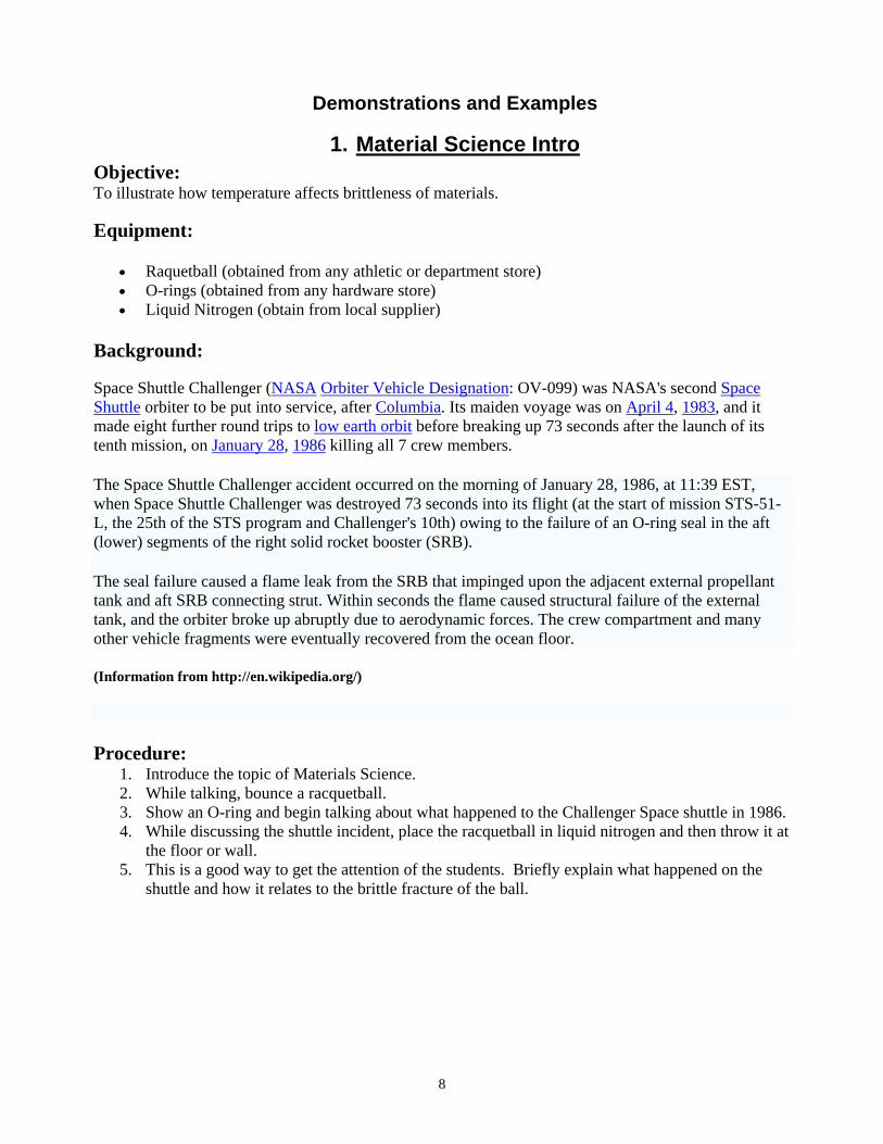
1. Material Science Intro Objective: To illustrate how temperature affects brittleness of materials. Equipment:
• Raquetball (obtained from any athletic or department store) • O-rings (obtained from any hardware store) • Liquid Nitrogen (obtain from local supplier)
Background: Space Shuttle Challenger (NASA Orbiter Vehicle Designation: OV-099) was NASA's second Space Shuttle orbiter to be put into service, after Columbia. Its maiden voyage was on April 4, 1983, and it made eight further round trips to low earth orbit before breaking up 73 seconds after the launch of its tenth mission, on January 28, 1986 killing all 7 crew members.
The Space Shuttle Challenger accident occurred on the morning of January 28, 1986, at 11:39 EST, when Space Shuttle Challenger was destroyed 73 seconds into its flight (at the start of mission STS-51-L, the 25th of the STS program and Challenger's 10th) owing to the failure of an O-ring seal in the aft (lower) segments of the right solid rocket booster (SRB).
The seal failure caused a flame leak from the SRB that impinged upon the adjacent external propellant tank and aft SRB connecting strut. Within seconds the flame caused structural failure of the external tank, and the orbiter broke up abruptly due to aerodynamic forces. The crew compartment and many other vehicle fragments were eventually recovered from the ocean floor.
(Information from http://en.wikipedia.org/)
Procedure: 1. Introduce the topic of Materials Science. 2. While talking, bounce a racquetball. 3. Show an O-ring and begin talking about what happened to the Challenger Space shuttle in 1986. 4. While discussing the shuttle incident, place the racquetball in liquid nitrogen and then throw it at
the floor or wall. 5. This is a good way to get the attention of the students. Briefly explain what happened on the
shuttle and how it relates to the brittle fracture of the ball.

9
2. Classifying Materials Objective: To have students identify the differences that exist between various types of materials. Equipment:
• Gather as many different examples of materials as you can find. Background:
In chemistry, a metal (Greek: Metallon) is an element that readily forms ions (cations) and has metallic bonds. Metals are sometimes described as a lattice of positive ions (cations) surrounded by a cloud of delocalized electrons. The metals are one of the three groups of elements as distinguished by their ionisation and bonding properties, along with the metalloids and nonmetals.
Intermetallics is the short summarizing designation for such intermetallic phases and compounds, i.e. chemical compounds between two or more metals with crystal structures which differ from those of the constituent metals. In a mechanical context, such compounds often offer a compromise between ceramic and metallic properties when hardness and/or resistance to high temperatures is important enough to sacrifice some toughness and ease of processing. They can also display desirable magnetic, superconducting and chemical properties, due to their strong internal order and mixed (metallic and covalent/ionic) bonding, respecitvely.
Polymer is a term used to describe a very large molecule consisting of structural units and repeating units connected by covalent chemical bonds. The term is derived from the Greek words: polys meaning many, and meros meaning parts [1]. The key feature that distinguishes polymers from other molecules is the repetition of many identical, similar, or complementary molecular subunits in these chains. These subunits, the monomers, are small molecules of low to moderate molecular weight, and are linked to each other during a chemical reaction called polymerization.
Composite materials (or composites for short) are engineered materials made from two or more constituent materials that remain separate and distinct on a macroscopic level while forming a single component. Nanocomposites are materials that are created by introducing nanoparticulates into a macroscopic sample material. The nanomaterials tend to drastically add to the electrical, thermal, and mechanical properties of the original materials
(Information from http://en.wikipedia.org/) Procedure: 1. Give students samples of different materials which you would find in a workshop. 2. Ask the students to assess the hardness of the materials on the Mohs Scale, classify them into polymers, metals, and so forth with the idea being that they get a feel for the differences that exist between various materials. There are a few tricks that you can pull…. 1. A steel and a stainless steel sample look the same, but given a magnet, they are all puzzled about whether or not the stainless is a steel or not. 2. A lump of rubber can cause confusion with the hardness test. Try leaving a scratch on the surface of this!!! Does this make it the hardest? Gets them thinking about hardness as a measure of plasticity. Also aluminum and an Al alloy look similar too. It is a platform for informal debate and discussion.

10
3. Ball Point Pen Objective: To identify materials that make up a ball point pen and explain why these materials meet the functional requirements that allow the pens to operate. Equipment:
• Ball point pens (obtain from anywhere – retractable pens work the best) Background:
In materials science, rather than haphazardly looking for and discovering materials and exploiting their properties, one instead aims to understand materials fundamentally so that new materials can be invented and created with the desired properties.
The basis of all materials science involves relating the desired properties and relative performance of a material in a certain application to the structure of the atoms and phases in that material through characterization. The major determinants of the structure of a material and thus of its properties are its constituent elements and the way in which it has been processed into its final form. These, taken together and related through the laws of thermodynamics, govern the material’s microstructure, and thus its properties.
An old adage in materials science says: "materials are like people; it is the defects that make them interesting". The manufacture of a perfect crystal of a material is physically impossible. Instead workers in the materials science field manipulate the defects in crystalline materials such as precipitates, grain boundaries (Hall-Petch relationship), interstitial atoms, vacancies or substitutional atoms in such a way as to create a material with the desired properties.
Not all materials have a regular crystal structure. Polymers display varying degrees of crystallinity. Glasses, some ceramics, and many natural materials are amorphous, not possessing any long-range order in their atomic arrangements. These materials are much harder to engineer than crystalline materials. Polymers are a mixed case, and their study commonly combines elements of chemical and statistical thermodynamics to give thermodynamical, rather than mechanical descriptions of physical properties.
(Information from http://en.wikipedia.org/) Procedure:
1. Collect a handful of ball point pens, preferably a retractable design (make sure you have enough for every pair of people in the audience).
2. Have everyone disassemble the pen (remind them they’re in trouble if they can’t reassemble the pen).
3. From the collection of parts, consider each part in turn, identifying the functional requirements of that part, identifying the material, and explaining why the material meets those functional requirements (Note: Using the Socratic question-based instructional style works really well).
4. Key components are: a. spring – high elastic limit – spring steel wire b. cams inside cap – slippery acetal plastic c. ink reservoir – inert relative to ink – brass or polyethylene d. ball – hard, round, accurately sized, controlled roughness surface and corrosion resistant
– tungsten carbide

11
5. Proceed to tell the audience that the carbide (at $100 per pound) is a bargain, compared to
harden steel (at $1 per pound). This is because the carbide is much more corrosion resistant (for those who chew their pens), and the amount of material in a ball is so minute that the cost of the material is invisible, compared to the cost of the manufacturing processes.
12
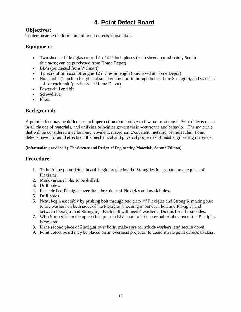
4. Point Defect Board Objectives: To demonstrate the formation of point defects in materials. Equipment:
• Two sheets of Plexiglas cut to 12 x 14 ½ inch pieces (each sheet approximately 5cm in thickness; can be purchased from Home Depot)
• BB’s (purchased from Walmart) • 4 pieces of Simpson Strongtie 12 inches in length (purchased at Home Depot) • Nuts, bolts (1 inch in length and small enough to fit through holes of the Strongtie), and washers
– 4 for each bolt (purchased at Home Depot) • Power drill and bit • Screwdriver • Pliers
Background:
A point defect may be defined as an imperfection that involves a few atoms at most. Point defects occur in all classes of materials, and unifying principles govern their occurrence and behavior. The materials that will be considered may be ionic, covalent, mixed ionic/covalent, metallic, or molecular. Point defects have profound effects on the mechanical and physical properties of most engineering materials.
(Information provided by The Science and Design of Engineering Materials, Second Edition)
Procedure:
1. To build the point defect board, begin by placing the Strongties in a square on one piece of Plexiglas.
2. Mark various holes to be drilled. 3. Drill holes. 4. Place drilled Plexiglas over the other piece of Plexiglas and mark holes. 5. Drill holes. 6. Next, begin assembly by pushing bolt through one piece of Plexiglas and Strongtie making sure
to use washers on both sides of the Plexiglas (meaning in between bolt and Plexiglas and between Plexiglas and Strongtie). Each bolt will need 4 washers. Do this for all four sides.
7. With Strongties on the upper side, pour in BB’s until a little over half of the area of the Plexiglas is covered.
8. Place second piece of Plexiglas over bolts, make sure to include washers, and secure down. 9. Point defect board may be placed on an overhead projector to demonstrate point defects to class.
13
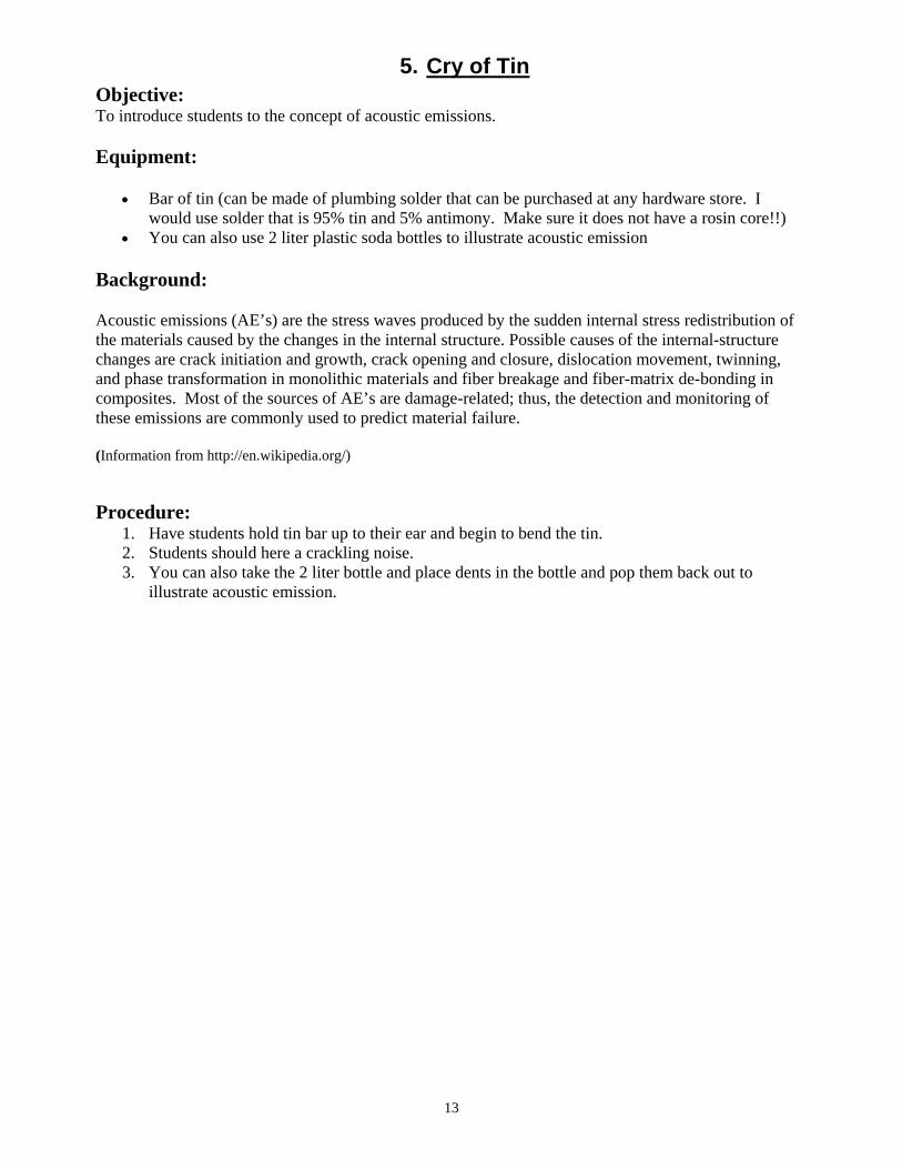
5. Cry of Tin Objective: To introduce students to the concept of acoustic emissions. Equipment:
• Bar of tin (can be made of plumbing solder that can be purchased at any hardware store. I would use solder that is 95% tin and 5% antimony. Make sure it does not have a rosin core!!)
• You can also use 2 liter plastic soda bottles to illustrate acoustic emission
Background: Acoustic emissions (AE’s) are the stress waves produced by the sudden internal stress redistribution of the materials caused by the changes in the internal structure. Possible causes of the internal-structure changes are crack initiation and growth, crack opening and closure, dislocation movement, twinning, and phase transformation in monolithic materials and fiber breakage and fiber-matrix de-bonding in composites. Most of the sources of AE’s are damage-related; thus, the detection and monitoring of these emissions are commonly used to predict material failure. (Information from http://en.wikipedia.org/) Procedure:
1. Have students hold tin bar up to their ear and begin to bend the tin. 2. Students should here a crackling noise. 3. You can also take the 2 liter bottle and place dents in the bottle and pop them back out to
illustrate acoustic emission.

14
6. Surface Tension Demo of Water Objective: To illustrate for students the magnitude of surface tension forces and also introduce them to the Griffith crack theory. Equipment:
• 2 plates of glass (size really doesn’t matter) • Glass of Water • 1 Quarter
Background: Surface tension is caused by the attraction between the molecules of the liquid, due to various intermolecular forces. In the bulk of the liquid each molecule is pulled equally in all directions by neighboring liquid molecules, resulting in a net force of zero. At the surface of the liquid, the molecules are pulled inwards by other molecules deeper inside the liquid, but there are no liquid molecules on the outside to balance these forces. (There may also be a small outward attraction caused by air molecules, but as air is much less dense than the liquid, this force is negligible.) All of the molecules at the surface are therefore subject to an inward force of molecular attraction which can be balanced only by the resistance of the liquid to compression. Thus the liquid squeezes itself together until it has the lowest surface area possible. (Information from http://en.wikipedia.org/) Procedure: 1. Take piece of glass from materials science kit. 2. Place a second piece of glass from the kit on top of the first. 3. Turn it over and watch it fall off. 4. Place a small amount of water between the two pieces of glass and turn it over. Both pieces of glass will stick together. 5. Next, take the quarter and softly place on top of the water in the glass. Quarter should float on top of the water.

15
7. Glass Fibers Objective: To illustrate how the viscosity of glass changes as a function of temperature. Equipment:
• Soft soda glass rod (Obtain from chemistry supply store or possibly a window store.) • Torch
Background:
Although glass is hard and solid it is actually a very viscous liquid. The viscosity is so thick that at room temperature the liquid flow of glass is extremely slow. The "wavy" appearance of very old windows is due to the flow of glass during the manufacturing process resulting in an uneven thickness. Modern window manufacturing methods can maintain a better control over the glass flow and produce windows of uniform thickness. By heating glass to a high temperature the viscosity can be decreased and glass fibers can be formed very easily.
Procedure:
1. Hold the two ends of the glass rod and heat the center using a laboratory torch. Depending on the length of the rod it may he necessary to wear heat resistant gloves to avoid burns.
2. The glass will become soft and turn yellow in the hot zone of the torch. Demonstrate the lowered viscosity by moving the ends of the glass rod such that the students can see that the hot glass behaves like putty.
3. As the glass becomes soft, pull the two ends apart as you remove the hot zone from the flame, forming a glass fiber.
4. The fiber can be bent a significant amount to demonstrate the elastic properties of glass.
Published in cooperation with Ames Laboratory U.S.D.O.E. and Department of Materials Science and Engineering Iowa State University.

16
8. Laboratory Experiments From the Toy Store Objective: - To quantitatively demonstrate the concepts of elasticity, plasticity, and the strain rate and temperature dependence of the mechanical properties of engineering materials. - To qualitatively demonstrate the basics of extrusion, including material flow, strain rate dependence of defects, lubrication effects, and the making of hollow shapes by extrusion. The two parts may be two separate experiments done at different times when the respective subjects are covered. - To demonstrate the importance of qualitative observation and the amount of information that can be gathered without quantitative measurements. Equipment:
• One or more containers (eggs) of formable putty (Silly putty, Nutty Putty) • One or more clay extrusion presses (made by Play-Doh) • Ice and a bowl (can use liquid nitrogen if available) • Low power heat source
Procedure: Part I of this experiment involves allowing students to manipulate the formable putty to illustrate the definitions and concepts of the mechanical properties of materials. While the students are unwrapping the putty, the definitions of elasticity and plasticity can be reviewed.
1) The students may form the putty into a smooth ball and bounce the ball on a rigid surface from a height of about 10cm and note the general height of the rebound and the lack of permanent deformation. The amount of deformation can be quantified by using the measuring stick.
2) The ball may then be placed in the bowl of ice (or liquid nitrogen) and cooled. It will be noticed that the ball flattens on the bottom illustrating creep. After the putty is cold, it can be reformed into a ball and bounced again from the same 10cm height and the amount of rebound noted. The rebound height will be higher than when warm indicating an increase in hardness with decreasing temperature.
3) Next, form the putty into a cylinder. The students pull the putty slowly lengthwise and note the extensive plastic deformation (Fig. 1). This is a graphic demonstration of the concept of ductility.
4) Reform the cylinder and quickly pull it apart. This should result in some plastic deformation and a sharp break. Cooling it in ice before doing this will give you better results.
5) You can also place putty in liquid nitrogen and shatter with a hammer illustrating the temperature dependence of deformation.
Part II of this experiment involves the use of a clay extrusion press such as the Play-Doh Fun Factory.
1) Using one of the dies, have a student slowly extrude a shape. A second shape should be extruded using a much greater speed. The first shape should have a smooth surface and the second should be irregular due to speed cracking, a common extrusion problem. A little bit of water can be placed on the inside and outside part of the die to demonstrate how lubrication helps to counteract the speed cracking effect.
2) Next, two experiments may be performed to demonstrate the material movement. In the first, two colors of clay are placed side-by-side with the intersection parallel to the extrusion axis. Extruding through a single-hole die shows that the two colors maintain their respective position. Placing the two colors so that the intersection is perpendicular to the extrusion axis and extruding demonstrates that the back color moves faster and moves inside the front color. The extruded shape can then be cut to show the extent of the movement. The amount of each color in a cross section varies along the length of the extrusion. Similar movement can also be demonstrated using the multi-small hole (spaghetti) die.
3) Information provided by: Laboratory Experiments from the Toy Store By H.T. McClelland Department of Manufacturing and
Industrial Technology Arizona State University
17
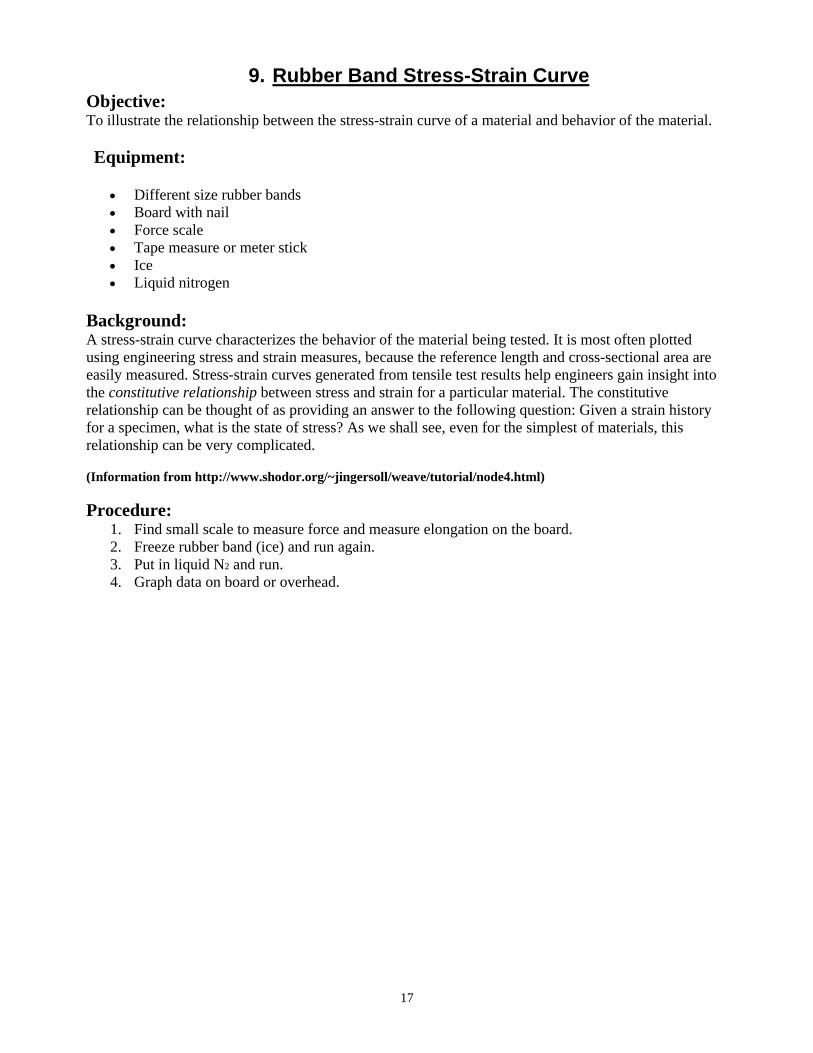
9. Rubber Band Stress-Strain Curve Objective: To illustrate the relationship between the stress-strain curve of a material and behavior of the material. Equipment:
• Different size rubber bands • Board with nail • Force scale • Tape measure or meter stick • Ice • Liquid nitrogen
Background: A stress-strain curve characterizes the behavior of the material being tested. It is most often plotted using engineering stress and strain measures, because the reference length and cross-sectional area are easily measured. Stress-strain curves generated from tensile test results help engineers gain insight into the constitutive relationship between stress and strain for a particular material. The constitutive relationship can be thought of as providing an answer to the following question: Given a strain history for a specimen, what is the state of stress? As we shall see, even for the simplest of materials, this relationship can be very complicated. (Information from http://www.shodor.org/~jingersoll/weave/tutorial/node4.html) Procedure:
1. Find small scale to measure force and measure elongation on the board. 2. Freeze rubber band (ice) and run again. 3. Put in liquid N2 and run. 4. Graph data on board or overhead.

18
10. Solubility and Immiscibility Objective: To illustrate the difference between solubility and immiscibility. Equipment:
• 2 Petri Dishes • Overhead projector • Water • Carbon tetrachloride • Iodine • Copper chloride
Background: Solubility is the amount of a solute that will dissolve in a specific solvent under given conditions. The dissolved substance is called the solute and the dissolving fluid (usually present in excess) is called the solvent, which together form a solution. The process of dissolving is called solvation, or hydration if the solvent is water. The chemistry term miscible refers to the property of various liquids that allows them to be mixed together. By contrast, substances are said to be immiscible if they cannot be mixed together, e.g., oil and water. (Information from http://en.wikipedia.org/) Procedure:
1. Take two petri dishes and place them on an overhead. 2. In the center of each dish there should be a pool of carbon tetrachloride in water. 3. Place drops of iodine in the pool of carbon tetrachloride and in the surrounding water (You
should see the iodine dissolve in the CT but not in the surrounding water). 4. In the other dish, place some copper chloride in the carbon tetrachloride and surrounding water
(Should see that the CC does not dissolve in the pool in the second dish but does in the surrounding water).

19
11. Heat Treating Piano Wire Objective: To illustrate the effects of thermal expansion and phase transformations on steel piano wire. Equipment:
• Steel Piano Wire • Wood Board • Screws • Some type of weight (a key may be used) • Variac (also known as a variable transformer)
Background:
Heat Treatment is a group of manufacturing techniques used to alter the hardness and toughness of a material. The most common application is metallurgical. Heat treatments are also used in the manufacture of many other materials, such as glass.
The techniques include annealing, case hardening, induction hardening, precipitation strengthening, tempering and quenching.
Steels can be heat treated to make them harder or softer. Different steels respond differently to heat treatment depending on its carbon content.
(Information from http://en.wikipedia.org/) Procedure:
1. String steel piano wire between two metal screws on a board 1 – 2 ft wide. 2. Connect a small variac to the screws and do the heat treatments using the variac. 3. By watching the suspended weight, students can see thermal expansion, but more
interesting are the phase transformations on heating and

20
12. Heat Treating Nails Objective: To illustrate the effects of heat treatment on steel. Equipment:
• Concrete nails ~ 60mm in length (obtain at hardware store)
• Plain carpenter nails ~ 80 mm in length
• Propane torch
• Beaker of water • Small vise • Hammer • Pliers • file
Background:
Heat Treatment is a group of manufacturing techniques used to alter the hardness and toughness of a material. The most common application is metallurgical. Heat treatments are also used in the manufacture of many other materials, such as glass.
The techniques include annealing, case hardening, induction hardening, precipitation strengthening, tempering and quenching.
Steels can be heat treated to make them harder or softer. Different steels respond differently to heat treatment depending on its carbon content. The concrete nails contain about 0.6% carbon and they can be austenitized, quenched, and tempered rather nicely. The carpenter nail contains less than 0.1% carbon and it cannot be hardened.
(Information from http://en.wikipedia.org/) Procedure:
1. Take a concrete nail and demonstrate to the students that the nail can be filed. Make a mark on the nail about 20 mm from the tip with the file.
2. Grasp the nail with the pliers and heat in the flame of the propane torch to austenitize the nail. (The nail should turn a bright orange color, approximately 850 degrees celsiuis) for austenitizing.)
3. Quench the nail in water by placing it in the beaker of water immediately. 4. Quenching will cause the steel to transform to martensite but it also cause tiny flakes of iron
oxide to be thrown from the surface of the nail. The flakes are readily visible inside the beaker. 5. When quenched to martensite, the nail is very brittle. 6. Clamp the nail about 25 mm from the tip into the vise, and pound the head with a hammer.
*Be careful to swing the hammer so that the flying fragment will move away from the audience.*
7. The nail should fracture on cue with nil bending. 8. Be sure to demonstrate to the class how the nail cannot be filed now. 9. Reheat the broken end (the part remaining in the vise) until you can see just a hint of red. This
will temper the nail making it plenty soft to bend at a 90 degree angle. Pound away with the hammer again to illustrate how it will not fracture once it’s been tempered.
10. Repeat same process with carpenter nail. It cannot be hardened.

21
13. Water Absorbing Polymer Objectives: To help students understand the various properties of polymers. Equipment:
• Agrosoke (purchased from Lowe’s) • 1 gallon of water
Background:
Agrosoke Root Watering Crystals were made specifically for improving plant growth with reduced water requirements. They make growing quality plants easier for everyone and are designed to be compatible with fertilizers and plant growth aids. These root watering crystals save water and time and can be used both indoors and outdoors. When wet, Agrosoke crystals turn into a gel and creates "mini reservoirs of water" around the root systems of plants. The plant's roots will pull this water (and any nutrients you add to it) from the gel as needed. Agrosoke crystals have strong structual stability, which enables them to reduce compaction so they will hold up under pressure instead of breaking into smaller particles.
(Information provided by http://www.agorganics.com/products/Agrosoke-Root-Watering-Crystals/11/206.html)
Procedure:
6. Scoop 3 tablespoons of agrosoke and place into a large clear container. 7. Pour 1 gallon of water into container. 8. Observe and discuss what happens.
22
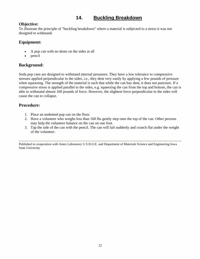
14. Buckling Breakdown Objective: To illustrate the principle of "buckling breakdown" where a material is subjected to a stress it was not designed to withstand. Equipment:
• A pop can with no dents on the sides at all • pencil
Background:
Soda pop cans are designed to withstand internal pressures. They have a low tolerance to compressive stresses applied perpendicular to the sides, i.e., they dent very easily by applying a few pounds of pressure when squeezing. The strength of the material is such that while the can bay dent, it does not puncture. If a compressive stress is applied parallel to the sides, e.g. squeezing the can from the top and bottom, the can is able to withstand almost 160 pounds of force. However, the slightest force perpendicular to the sides will cause the can to collapse.
Procedure:
1. Place an undented pop can on the floor. 2. Have a volunteer who weighs less than 160 lbs gently step onto the top of the can. Other persons
may help the volunteer balance on the can on one foot. 3. Tap the side of the can with the pencil. The can will fail suddenly and crunch flat under the weight
of the volunteer.
Published in cooperation with Ames Laboratory U.S.D.O.E. and Department of Materials Science and Engineering Iowa State University

23
15. Glass Objective: To illustrate the mechanical properties of glass Equipment:
• Pane of tempered glass (Obtain from local glass or window store) • Two Chairs
Background:
Tempered glass for windows is made by blowing air on the outer surfaces of the glass pane such that they cool very rapidly while the glass in the interior is still warm. When the inside glass cools it shrinks and contracts. This contraction effectively means that the inside glass "pulls" on the outside glass; in engineering terms the outer surfaces are in compression while the inner glass is in tension. The compressive stress gives the glass pane great strength as long as the outer surface is not chipped. If the glass is chipped such that a crack reaches the interior glass that is under tension, the glass pane will shatter as the tensile forces are suddenly released.
Procedure:
1. Place the pane flat with the edges supported on two chairs so you have a platform 18" or so off the ground with about 12"-18" of glass unsupported between the chairs. (You may also suspend the pane on 2"x4"s placed on the ground.)
2. Slowly stand on the pane such that your entire weight is on the unsupported portion of the glass. The glass should hold up to 400 pounds easily. (N.B. It is extremely rare that the pane will break. If the glass does break it will break in the plane of the glass meaning that glass pieces will fly out parallel to the floor. it is best to have students remain at least 10 feet away and wear safety goggles while doing this demonstration.)
If you wish to demonstrate the effect of a flaw in the glass, the experiment may be continued as follows:
3. Clear everyone from the area. Wear safety glasses. (The pane of glass may be placed in a clear plastic bag if desired.)
4. Support one corner of the pane on one of the chairs or rest it on the floor. Grip the opposite corner with the pliers and squeeze to crack the glass. The pane will shatter, spreading glass over a large area. (Most of the glass will fly in the plane of the pane of glass. Make certain the pane is not pointing toward the class as the glass will fly several feet!)
Published in cooperation with Ames Laboratory U.S.D.O.E. and Department of Materials Science and Engineering Iowa State University

24
16. Fatigue Demo Objective: To illustrate the effects of fatigue on a metal. Equipment:
• Tin solder (obtained from hardware store) cut into 20 cm pieces
Background: In materials science, fatigue is the progressive, localized, and permanent structural damage that occurs when a material is subjected to cyclic or fluctuating strains at nominal stresses that have maximum values less than (often much less than) the static yield strength of the material. The resulting stress may be below the ultimate tensile stress, or even the yield stress of the material, yet still cause catastrophic failure. (Information from http://en.wikipedia.org/) Procedure:
1. Repeatedly bend a piece of the tin solder at 30º angles until the piece breaks. Count the number of cycles it takes to break the piece.
2. Repeat at 60º angles. 3. Repeat at 90º angles. 4. Plot cycles to failure vs bend angle on the board or overhead.
25
17. Memory Metal Objective: To illustrate the shape-memory effect as a function of temperature. Equipment:
• Memory wire (Obtain from local orthodontist or Edmund's Scientific) • Hot water • Tongs
Background:
Nitinol or "memory metal" undergoes a reversible shape change as a function of temperature. The wire is formed into a specific shape at high temperature and then cooled very rapidly. At room temperature the wire can be bent into any shape but once the temperature is raised (to approximately 95-200° F depending on the particular alloy) the wire will once again form into the original shape. Orthodontists commonly use memory wire in braces.
Procedure:
1. Show the students the initial shape of the wire. 2. Deform the wire by straightening it or wrapping it around your finger. 3. Lower the wire into hot water (hot coffee temperature is fine). The wire will return to the original
shape. 4. If orthodontic wire is used, bend the wire around a pencil to prevent the heat from getting to your
fingers causing the wire to return to its original shape.
Published in cooperation with Ames Laboratory U.S.D.O.E. and Department of Materials Science and Engineering Iowa State University

26
18. Work Hardening Objective: To illustrate how metals get harder as you bend them. Equipment:
• Copper rod, (or pipe) 1/4" diameter, about 18" long (Obtain from plumber or metal shop) • Propane torch
Background:
How easily a metal bends, how hard a metal is, and how far a metal can be stretched before it breaks are all measures of mechanical properties. These properties are directly related to the atomic structure of the metal. If a pure metal is heated to a high temperature and cooled it will often be very soft since the atomic structure is very uniform. If the metal is bent the atomic structure will be disturbed and the metal will get much harder.
Procedure:
1. Clamp the copper rod by one end in a ring stand and using a propane torch (two or three are better) start heating at the far end until the tip is glowing bright red.
2. Slowly move the heat in towards the clamped end so that the red-hot hot zone moves down the length and the entire rod has been heated. It is not necessary to keep the whole rod glowing at the same time; a hot zone 1" or so in width is fine as long as you move it down the whole length.
3. Cool the rod by placing it in a sink full of water or by spraying water over the rod. Be careful not to burn yourself. The bar will now be very soft, so don't bend it! You may want to lightly sand the outside to remove any oxide.
4. Hand the bar to the smallest student in the room and ask them to bend it. They should be able to do this easily. However, it will become very hard due to the bending.
5. Pass the rod to another student and ask them to try and straighten it. They will find this very difficult due to the work hardening effect.
6. This demo can be repeated simply by reheating the Cu, straightening it back out, then reheating again.
7. A coat hanger can also be used for this demo. Bend the straight section of the coat hanger to a "U", then immediately try to bend it back straight. The curve of the "U" will remain bent due to the work hardening effect in this area.
27
19. Tempered Steel Objective: To illustrate how heat can be used to "temper" a steel, making it very strong instead of brittle. Equipment:
• A piece of drill rod steel, 1/16" in diameter, 18" long. "Drill rod", which is = 0.9% C, can be obtained from most metal shops or possibly welding shops. (Very large bobby pins are also suitable for this experiment.)
• Torch • Beaker of water
Background:
The atomic arrangement of atoms in steel changes with temperature. At room temperature the atoms form a cube with one atom in the center of the cube body (called body-centered cubic or BCC) but by heating steel to a high temperature this arrangement can be changed to a cube with atoms on the faces (called face-centered cubic or FCC). if the hot steel is plunged into cold water (called "quenching") the atoms do not have time to go back to the favored BCC arrangement. Instead, a complex structure results which is very brittle. If the steel is reheated slightly, the atoms move slightly and the atomic arrangement becomes very hard and tough. This reheating is called tempering and most tool steels have been quenched and tempered.
Procedure:
1. Cut the rod in half so that you have two pieces, approximately 9" long. 2. Bend the two rods into "U" shapes. 3. Heat the curve of one "U" until it becomes bright orange using the torch. (You can hold the two
ends of the "U" in your hand during heating, steel has a very low thermal conductivity so the ends will not get hot.) Immediately plunge the hot section of the rod into a container of cold water. This is called quenching. (Note: if large bobby pins are used they are often coated with a plastic resin coating which will burn off in the flame.)
4. Repeat Step 3 above with the second "U". Once this "U" has been quenched in the water, reheat it slightly in the flame. It is only necessary to get the metal warm, DO NOT get it so hot as to cause the color to change. This is called tempering.
Pulling the two ends of the two “U”s apart. The steel which was only quenched will be very brittle and will break easily. The quenched and tempered “U” will be so strong and touch in the region of the “U” that it will be
impossible to get it to bend in this region.
1
1 Published in cooperation with Ames Laboratory U.S.D.O.E. and Department of Materials Science and Engineering Iowa State University.
28
20. A Demonstration of Chill Block Melt Spinning of Metal Objective: To show the simplicity of the chill block melt spinning process. Equipment:
• Power Drill • 9” Aluminum Baking pan • Pyrex Glass Tube (10-12mm diameter) • Rubber hose • Hand operated pressure bulb • Tin solder (95% tin and 5% antimony) • Nuts and bolts • Propane torch
Background:
One of the most exciting adventures in materials in recent times has been the discovery of amorphous metals and the pursuit of methods of manufacturing various alloys into various shapes which are amorphous. Some of these alloys possess electrical properties which are extremely beneficial, whereas others offer different benefits such as corrosion resistance and no solidification shrinkage anomalies. There are a number of techniques for producing such amorphous shapes, but one of the earliest systems used is now referred to as chill block melt spinning.
Chill block melt-spinning (CBMS) processes are used to make rapidly solidified microcrystalline and amorphous alloy ribbon, flakes, etc. Fundamentals of CBMS processes are discussed in light of recent advances. Special regard is given to ribbon geometric defects (edge serrations, surface asperities, etc.). Photomicrographs of CBMS ribbon solidification microstructures are used to compare local solidification rates, especially in the vicinity of ribbon defects. Procedure:
1. Since it is advantageous to use low melting temperature metals for this demo, a Pyrex tube works well as an ejection tube. Any tube size can be used, but a 10-12 mm size is convenient.
2. One end of the tube should be sealed by heating and drawing the glass and the heated mass, then redrawn to produce a conical cavity with a small apex angle as illustrated in figure 1.
3. The glass wall is then ground away to produce an orifice approximately 300-500 microns in diameter.
4. Cut the tube to a length of about 25 cm. 5. Attach rubber hose with bulb on the end. 6. Construct the chill block by using the 9” aluminum cake pan. Buff the exterior rim to a high sheen 7. Find the center of the pan by balancing it on the point of a pencil. 8. Drill a hold through the center. 9. Insert bolt and secure with nuts. Mount finished chill block onto power drill. 10. Melt a tin rod in the Pyrex tube by heating the tube slowly with the propane torch. Once the tin
liquefies, it can be ejected in a continuous stream onto the outer rim of the aluminum pan. (If the free fall of the stream is sufficiently great to allow solidification before impingement on a solid surface, and if the stream velocity is sufficiently great to cause the Rayleigh break-up to be beyond the point of solidification, then a round tin wire will be produced.)
Additional Notes:

29
If the stream of molten tin previously described is directed at the rotating outer flat portion of the cake pan rim, then the circular cross section molten stream will be converted into a flat solid ribbon, the thickness and continuity of which will be dependent on the drill speed. A standard hand drill will run at about 1000 revolutions per minute and the rim surface of the cake pan will be traveling at approximately 1200cm per second. The ribbon is therefore cast at a speed of 1200cm per second. This is by no means the casting limit! Substitution of a higher speed motor will result in thinner fibers, higher quench rates, and greater casting speeds. Although the dwell time (or distance) of the tin on the wheel is very small, it will tend to lengthen if the wheel becomes warm by extended operation. It will be noticed that by controlling the point of impingement of the molten stream, one also controls the emanating trajectory of the solid fiber. Best results are obtained by using small attack angles (approximately 30 degrees) and molten stream flight distances of about 20 – 50 mm.
A Demonstration of Chill Block Melt Spinning of Metal Robert B. Pond
Department of Materials Science and Engineering
John Hopkins University
30
21. Temperature Dependent Electrical Conductivity of Soda-Lime Glass
Objectives: To demonstrate the difference between the electrical conductivity of metals and' ceramics.. Equipment:
• Strips of ordinary window glass, either single or double strength approximately • 1 x 5 cm • 10 - 12 gauge copper wire • 75 or 100 watt bulb • Socket mounted on wooden block • Wood screws to mount contact wires • Electrical cord and plug • Propane torch to heat glass
Background: This material is suitable as a demonstration for typical students of chemistry, physics or materials science at the high school level or above. Additional depth could be provided by comparisons of temperature conductivity behavior with typical metals and other ceramics, or by using a DC power supply to observe polarization effects as described below. Also, ordinary window glass is a “soft” glass that contains a relatively large percentage of ions, such as sodium, that conduct current when the glass is heated. Other glasses have different temperature dependence of electrical conductivity: Pyrex for instance may be difficult to heat sufficiently to light the bulb. Fused silica contains no added fluxing agents, and so is a thousand times less conductive at 1000 Kelvin than the soda-lime aluminosilicate glass shown in Fig. 1. Procedure: 1. Begin by reviewing the principles of current conduction through water when ions are present. 2. Next, discuss the difference between electrical conduction in a metal (free or delocalized electrons) and a glass or ceramic (in glass, ions; in other ceramics, either ions or electrons). Figure 1 or its equivalent can be used to clarify the great difference in the temperature dependence of electrical resistivity (the reciprocal of electrical conductivity) of metals and ceramics, resulting from these different mechanisms. *Note* The log scale on the resistivity axis is necessary to show the large change in the electrical resistivity of the glass or zirconium dioxide ceramic. The electrical resistivity of the metal increases by a factor of about 13 over the temperature range, although it is not obvious because of the log axis. This increase is caused when electrons are impeded by vibrating iron atoms; these vibrations increase with temperature. The current carriers present in ceramic materials are bonded too strongly to conduct much electricity at low temperature, but at higher energy they become increasingly mobile and able to carry more current. 3. The instructor or students should build the simple apparatus shown in Figure 2. The light bulb, which is in the series circuit with the specimen, provides a visual indication that the resistance of the specimen has dropped enough that the current passing through the bulb filament is about 1 ampere. The bulb also provides a current limiter.

31
4. Insert the glass specimen into the wire contacts as shown in Figure 2, so that 1 to 2 cm of glass is between the contacts. 5. Plug the tester into a 110 V outlet, and observe that the light bulb does not glow. (It may be useful to insert an AC ammeter into the circuit to provide another indication of current flow.) 6. Next, light the torch and carefully heat the glass, keeping the flame moving to avoid breaking the glass by thermal shock. The entire length of glass between the contacts should be heated, especially the contact areas. 7. At about the time the' glass begins to glow, the bulb will light. Increased heating will brighten the bulb indicating that glass is a better conductor as the temperature increases. 8. Remove heat from the glass and allow it to cool. The glass will finally cool to the point where it no longer conducts sufficiently to light the bulb. As the glass cools, it may be possible to observe what appear to be tiny sparks inside the glass; these can be quite beautiful and are probably caused by plasma discharge across bubbles or cracks in the glass. 9. The temperature dependence of electrical conductivity in other ceramics can be demonstrated using the same apparatus as for the glass. 10. A 0.3 cm rod of zirconium oxide, if carefully heated, will conduct sufficiently to light the bulb. The conduction mechanism in this case is the movement of oxygen ions between oxygen vacancies in the structure. 11. Alternatively, a piece of silicon carbide heating element or furnace igniter can be used. In this case, the conduction is by means of electrons that become able to move because of thermal energy supplied by heating. 12. For another comparison, a steel nail of approximately 0.3 cm diameter will conduct over the entire temperature range, and the bulb will not dim perceptibly when the nail is heated.

32

33
22. Superconductivity Experiment Objective: To illustrate the principles of superconductivity and the Meissner effect. Equipment:
• Superconductivity kit (Edmund Scientific, $37.00) • Liquid nitrogen (Inquire at welding supply dealers and/or doctor's offices as to the closest source.
Liquid nitrogen is cheaper than milk.)
Background:
A superconductive material carries an electrical current with no loss of electricity due to resistance. Superconductive materials also repel magnetic fields. This is termed the Meissner effect.
Procedure:
1. Place the superconductor pellet in a petri dish. The petri dish can be insulated somewhat by making a depression in a large piece of styrofoam and placing the petri dish in this depression. (The Edmund Scientific kit may provide a holder.)
2. Pour in liquid nitrogen until the pellet is cold and the LN2 doesn't evaporate immediately.
3. Using plastic tweezers, place a small FeNdB magnet chip (or the magnet provided by Edmund) over the top of the superconductor. The superconductor will exclude the magnetic field and the magnet will remain suspended in thin air over the pellet.
Published in cooperation with Ames Laboratory U.S.D.O.E. and Department of Materials Science and Engineering Iowa State University

34
23. Index of Refraction Demo Objective: To demonstrate how glass and corn oil have the same index of refraction. Equipment:
• Glass rods • Corn oil • Beaker or graduated cylinder
Background: The refractive index (or index of refraction) of a material is the factor by which the phase velocity of electromagnetic radiation is slowed in that material, relative to its velocity in a vacuum. Procedure:
1. Place glass rod into graduated cylinder. 2. Pour in corn oil slowly. 3. Glass rod should not be visible inside cylinder due to the reflectance and scattering of light at
oil/glass interface which is zero..
35
24. Karo Syrup Experiment Objective: To demonstrate birefringence, dispersion, and polarization effects of a transparent material. Equipment:
• Karo syrup (grocery store, = $2.00) • Two polarizing sheets (Edmund Scientific, = $20.00) • Overhead • Tall graduated cylinder • Cardboard
Background:
When light passes through Karo Syrup the optical properties of the sugar molecules cause the light rays to rotate. The amount of rotation depends on the thickness of the syrup layer through which the fight passes.
Procedure:
1. Place a piece of cardboard on an overhead with a hole cut into it the same diameter as your graduated cylinder.
2. Place a polarized sheet on the cardboard. 3. Place the graduated cylinder over the hole in the cardboard. 4. Have a student hold the second polarized sheet over the top lens of the overhead so no light reaches
the screen. 5. Pour the syrup slowly into the cylinder. Different colors of light will be visible as the thickness
increases. 6. Have the student rotate the polarized sheet they are holding. Different colors will be seen at
different angles.
Published in cooperation with Ames Laboratory U.S.D.O.E. and Department of Materials Science and Engineering Iowa State University
36
25. Permanent Magnets Objectives: To illustrate the magnetic properties of Fe-Nd-B permanent magnets and the eddy current response of nonmagnetic conductors to a strong magnetic field. Students should realize that all conductive materials are affected by magnets. Equipment:
• Fe-Nd-B permanent magnets of various sizes (Edmund Scientific, = $3.00 - $300.00 depending on size and number ordered). Large cow magnets (made of Cobalt-Samarium) also work reasonably well although the effect is reduced. These can be obtained from veterinarians for = $5.00 - $10-00 (or from meat slaughter houses for free).
• Thick (1/41, at least) plates of copper, aluminum, plastic. (Obtain from a metal working shop or salvage yard.)
• Tubes of different materials, e.g., copper, stainless steel, and PVC plastic. (Obtain from a plumber.) Tubes should have an inner diameter slightly larger than the magnet.
Background:
Fe-Nd-B magnets have the highest energy density of all commercial magnets. They are used in a number of devices used to study materials, as well as in a number of household electronic devices. The phenomenon of eddy currents is used extensively in the area of non-destructive-evaluation to determine whether small cracks invisible to the naked eye are present in metallic structures.
Procedure:
1. Stick two magnets to each other through the thickness of your hand or the arm of a younger student and slowly move the magnet up the volunteer's arm as far as it will go. The larger the magnets the greater the thickness of flesh through which the field penetrates. Magnets 1/4" square should stick through the palm of a hand.
2. Flip the bottom magnet over and watch the top one flip by itself. 3. Demonstrate the principle of eddy currents by having students wave a magnet over the surface
of the plates as near as possible without scraping the surface. Eddy currents are induced in conductors so you will feel nothing with plastic, very strong eddy currents in Cu since it is a good conductor, and the Al will be in between.
4. Place the magnets on the plates and tilt them until the magnet starts to slide. Due to the eddy currents opposing gravity you will have to tilt the Cu to a high angle before the magnet starts to slide.
5. Drop a small magnet through the Cu tube. Instead of falling straight through the eddy currents will oppose gravity and it may take 1-3 seconds for the magnet to fall through a tube 18" long. Allow students to look down the tube after you drop the magnet; it almost looks as if the magnet is floating down the length of the tube.
6. Experiment with tubes and plates made from different materials.
Published in cooperation with Ames Laboratory U.S.D.O.E. and Department of Materials Science and Engineering Iowa State University

37
26. Thermal Insulation Objectives: To illustrate thermal conductivity of fiber insulation. Equipment:
• Propane Torch • Some type of fibrous insulation (can be purchased at hardware store – ask for insulation used by
plumbers)
Background:
Heat is the internal kinetic, vibrational energy that all materials contain (except at absolute zero). Heat spontaneously flows from a high temperature region to a low temperature region, and the greatest heat flow occurs through the path of least resistance.
The proximity of a high temperature region to a low temperature region constitutes a temperature gradient. Thermal insulation maintains a thermal gradient by reducing the flow of heat across the temperature gradient.
Insulation exists in most large appliances, for example, in ovens, refrigerators, freezers, and water heaters. In some cases, the insulation serves to prevent heat loss to the environment. In other cases, it serves to prevent heat gain from the environment.
(Information from http://en.wikipedia.org/) Procedure:
1. Ask for a volunteer. 2. Place fibrous insulation board on the hand of the volunteer (make sure correct side is up). 3. Using a propane torch, heat front surface for as long as needed to illustrate point. 4. Have student feel the front side of the insulation versus the back side.
38
27. Thermal Shock Demo Objectives: To illustrate thermal expansion and thermal shock. Equipment:
• Piece of pyrex glass (can be purchased at Walmart – cookware) • Piece of soda-lime glass (any type of bottle glass) • Blowtorch or Bunsen burner will suffice
Background:
In physics, thermal expansion is the tendency of matter to increase in volume or pressure when heated. For liquids and solids the amount of expansion will normally vary depending on the material's coefficient of thermal expansion. When materials contract, tensile forces are created. When things expand compressive forces are created.
Thermal shock is the name given to cracking as a result of rapid temperature change. Glass and ceramic objects are particularly vulnerable to this form of failure, due to their low toughness, low thermal conductivity, as well as their high-melting point (which often leads to their use in high-temperature applications.) (Information from http://en.wikipedia.org/) Procedure:
1. Heat pyrex and soda-lime glass with propane torch. 2. Quench in water. 3. The pyrex will not fracture while the soda-lime should fracture into small pieces.

39
28. Corrosion and Passivation Objectives: To illustrate the principles of corrosion and passivation of steel. Equipment:
• A piece of steel. "Drill rod" which is = 0.9% C can be obtained form most metal shops or possibly welding shops.
• Concentrated nitric acid • Beakers • Water • A probe or small chemical spatula • Tongs
Background:
All metals oxidize or rust. This is termed corrosion. For many metals the rust layer is so thin it is transparent and so adherent that it protects the metal from further rust. This is the case for aluminum and stainless steel. In some cases the oxide builds up slowly and is only partially protective such as for silver and copper. In other cases the rust does not protect the metal at all. This is the case for most steels.
Procedure:
9. PERFORM THIS EXPERIMENT IN A HOOD! 10. Place a small piece of the steel drill rod in a beaker. 11. Pour concentrated nitric acid slowly into the beaker. The strong oxidizing environment of the nitric
acid will cause a very adherent oxide or rust to form very quickly and protect the metal from further corrosion.
12. Dilute the acid by pouring water into the beaker. Pour the water in very slowly so as not to disturb the (invisible) oxide layer on the steel.
13. Using the spatula or a probe, scratch the surface of the steel. The scratch will expose unprotected metal to the weak acid and corrosion will begin.
14. Corrosion will be very rapid and will generate a large amount of heat and colored, noxious fumes. Only perform this experiment in a hood!
15. Remove the steel from the diluted acid solution and rinse to stop the reaction.
Published in cooperation with Ames Laboratory U.S.D.O.E. and Department of Materials Science and Engineering Iowa State University
40
29. More Surface = Faster Reaction
Objective: The purpose of the following activities is to give you more experience with examining the effects of changing surface to volume ratios. Faster explosion looks at the effect of different surface area to volume ratios on the speed of reaction. Safety Precaution: Do not eat or drink anything in the lab! Wear safety goggles! Equipment:
• Two empty film canisters and their lids (obtain free from Walmart film department) • One tablet of Alka Seltzer tablet • Pack of Mentos • Water • Diet Coke • One small mortar and pestle • Timer
Procedures: 1. Break the Alka Seltzer tablet in half as exactly as you can. 2. Put one of the halves of the Alka Seltzer tablet into the mortar bowl and crush it with the pestle until it is finely granulated. 3. Fill each film canister halfway with tap water. 4. Put the ½ of the uncrushed Alka Seltzer and theh ½ of the crushed Alka Seltzer each into a different film canister at the same time. Quickly put their lids on. 5. Record the amount of time it takes for each canister to blow its lid off. 6. Rinse the film cans and repeat 1-5 using the Coke product and mentos.

41
The most exciting phrase to hear in science, the one that heralds new discoveries, is not ‘Eureka!’ (I found it!), but ‘That’s funny…’
Isaac Asimov (1920 - 1992)