Demonstration of a Piston Plug feed System for Feeding/67531/metadc841688/m2/1/high... · 7 Figure...
104
Demonstration of a Piston Plug feed System for Feeding Coal/Biomass Mixtures across a Pressure Gradient for Application to a Commercial CBTL System FINAL SCIENTIFIC/TECHNICAL REPORT Reporting Period Start Date: 10/01/2008 Reporting Period End Date: 06/30/2011 Principle Author: Santosh K Gangwal October 2011 DOE Award Number: DE-NT0006523 Southern Research Institute Advanced Energy and Transportation Technologies 5201 International Drive, Durham, NC 27712
Transcript of Demonstration of a Piston Plug feed System for Feeding/67531/metadc841688/m2/1/high... · 7 Figure...
Demonstration of a Piston Plug feed System for Feeding Coal/Biomass Mixtures across a Pressure Gradient
for Application to a Commercial CBTL System
FINAL SCIENTIFIC/TECHNICAL REPORT
Reporting Period Start Date: 10/01/2008
Reporting Period End Date: 06/30/2011
Principle Author: Santosh K Gangwal
October 2011
DOE Award Number: DE-NT0006523
Southern Research Institute Advanced Energy and Transportation Technologies
5201 International Drive, Durham, NC 27712

2
Disclaimer This report was prepared as an account of work partly sponsored by an agency of the United
States Government. Neither the United States Government nor any agency thereof, nor any of
their employees, makes any warranty, express or implied, or assumes any legal liability or
responsibility for the accuracy, completeness, or usefulness of any information, apparatus,
product or process disclosed, or represents that its use would not infringe privately owned rights.
Reference herein to any specific commercial product, process or service by trade name,
trademark, manufacturer, or otherwise does not necessarily constitute or imply its endorsement,
recommendation, or favoring by the United States Government or any agency thereof. The views
and opinions of author expressed herein do not necessarily state or reflect those of the United
States Government or any agency thereof.
3
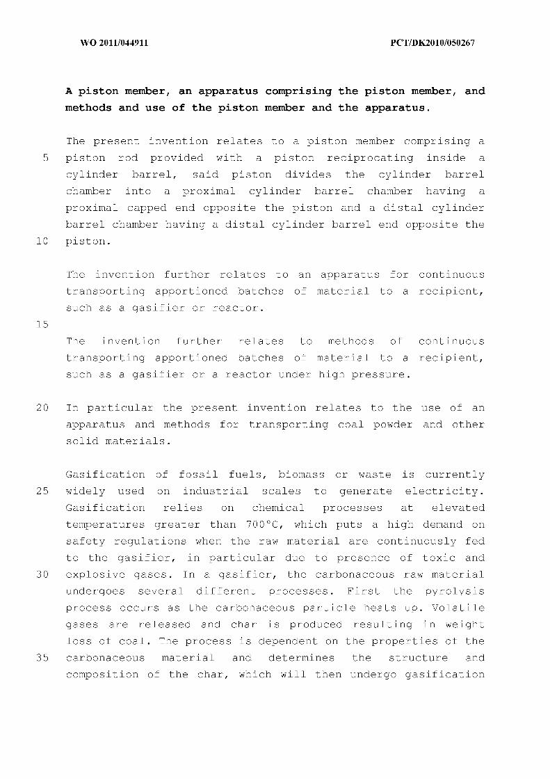
Abstract
Producing liquid transportation fuels and power via coal and biomass to liquids (CBTL) and
integrated gasification combined cycle (IGCC) processes can significantly improve the nation’s
energy security. The Energy Independence and Security Act of 2007 mandates increasing
renewable fuels nearly 10-fold to >2.3 million barrels per day by 2022. Coal is abundantly
available and coal to liquids (CTL) plants can be deployed today, but they will not become
sustainable without large scale CO2 capture and storage. Co-processing of coal and biomass in
CBTL processes in a 60 to 40 ratio is an attractive option that has the potential to produce 4
million barrels of transportation fuels per day by 2020 at the same level of CO2 emission as
petroleum.
In this work, Southern Research Institute (Southern) has made an attempt to address one of the
major barriers to the development of large scale CBTL processes—cost effective/reliable dry-
feeding of coal-biomass mixtures into a high pressure vessel representative of commercial
entrained-flow gasifiers. Present method for dry coal feeding involves the use of pressurized
lock-hopper arrangements that are not only very expensive with large space requirements but
also have not been proven for reliably feeding coal-biomass mixtures without the potential
problems of segregation and bridging.
The project involved the development of a pilot-scale 250 lb/h high pressure dry coal-biomass
mixture feeder provided by TKEnergi and proven for feeding biomass at a scale up to 6 ton/day.
The aim of this project is to demonstrate cost effective feeding of coal-biomass mixtures (50:50
to 70:30) made from a variety of coals (bituminous, lignite) and biomass (wood, corn stover,
switch grass). The feeder uses a hydraulic piston-based approach to produce a series of plugs of
the mixture that act as a seal against high back-pressure of the gasification vessel in to which the
mixture is being fed. The plugs are then fed one by one via a plug breaker into the high pressure
gasification vessel. A number of runs involving the feeding of coal and biomass mixtures
containing 50 to 70 weight % coal into a high pressure gasification vessel simulator have shown
that plugs of sufficient density can be formed to provide a seal against pressures up to 450 psig if
homogeneity of the mixture can be maintained. However, the in-homogeneity of coal-biomass
mixtures can occur during the mixing process because of density, particle size and moisture
differences. Also, the much lower compressibility of coal as opposed to biomass can contribute
to non-uniform plug formation which can result in weak plugs. Based on present information,
the piston plug feeder offered marginal economic advantages over lock-hoppers. The results
suggest a modification to the piston feeder that can potentially seal against pressure without the
need for forming plugs. This modified design could result in lower power requirements and
potentially better economics.
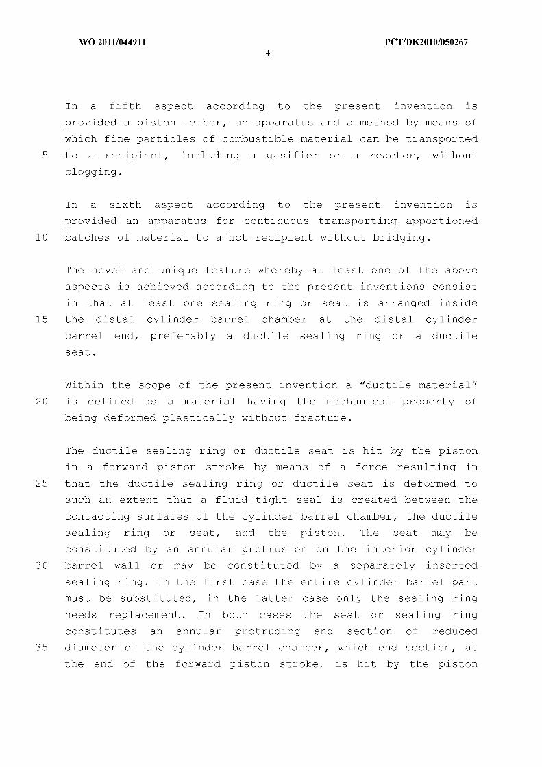
4
Table of Contents Disclaimer 2
Abstract 3
Executive Summary 5
Introduction and Background 10
Objectives 13
Equipment Description 14
Experimental 21
Results and Discussion 38
Preliminary Engineering and Economic Evaluation 44
Conclusions and Summary 46
References 48
Appendix A: Coal-Biomass Mixture Properties 49
Appendix B: Run Log Book 54 Appendix C: TKEnergi Patent Application for Modified Feeder 65
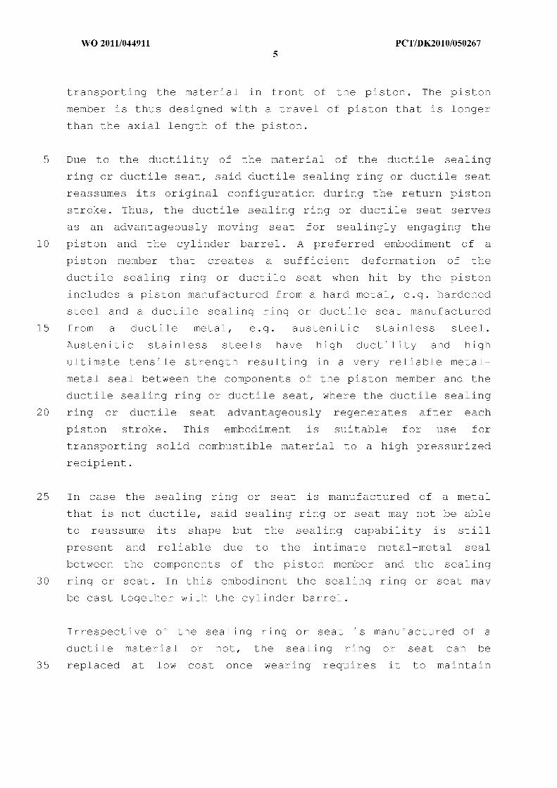
5
Executive Summary
Due to a finite petroleum resource and increased risk of supply disruption, alternative non-
petroleum sources for transportation fuels need to be developed. Coal and biomass are two of the
most plausible alternative fuels for replacing petroleum as a source of transportation fuels. Coal
and biomass to liquids (CBTL) refers to technologies that co-gasify coal and biomass in a high
pressure gasifier and then convert the syngas produced to liquid fuels via Fischer-Tropsch
synthesis. CBTL is attractive to develop since plants using 60 % coal and 40 % biomass can
produce 4 Mbpd by 2020 at equivalent CO2 emissions as petroleum without carbon capture and
sequestration (CCS). This is because the use of 40 % biomass reduces the impact of the total
CO2 emissions. CBTL plants are also economically competitive with petroleum based plants at
current crude oil prices. However, further performance improvements and cost reductions in
CBTL plants are needed to reduce investor risk in these plants that can cost upwards of several
hundred million dollars.
This report addresses a major technical barrier faced by developers of commercial CBTL plants--
availability of a cost-effective and reliable feed system for feeding coal-biomass mixtures into a
high pressure entrained flow gasifier. Lock hoppers, the present commercial method of feeding
these fuels individually, have not yet been proven for coal-biomass mixtures. They may
develop rat holes, or segregate and bridge due to compaction. Also, a number of disadvantages
of lock-hopper based systems such as high capital and operating costs, and low cold gas
efficiency at high pressures have encouraged the development of alternative feeding systems.
These include feeders such as those being developed by General Electric, Pratt and Whitney
Rocketdyne, and TKEnergi that work like solids pump rather than use an inert high pressure gas
for maintaining front pressure and pushing the solids in to the high pressure gasifier.
In this work, the testing of a 250 lb/h high pressure pilot-scale piston plug feeder designed and
provided by TKEnergi to Southern is described. The feeder technology from TKEnergi, based
on 3 pistons operating in sequence, is an alternative to expensive and bulky lock hopper systems.
The aim of the project is to demonstrate cost effective feeding of coal-biomass mixtures (50:50
to 70:30) made from a variety of coals (bituminous, lignite) and biomass (woody, corn stover,
switch grass) against pressures up to 450 psig. Specific objectives include:
• Specifying an appropriate biomass pretreatment system,
• Demonstrating the ability of this pretreatment system and TKE’s feed system proven for
biomass to co-feed a variety of biomass and coal mixtures into a simulated high pressure
environment similar to that encountered in CBTL facilities, and
• Evaluating the engineering and economic viability of the proposed
at large scale CBTL processes.
The equipment set up at Southern
necessary pretreatment of biomass and mixing it with coal for feeding into a high pressure
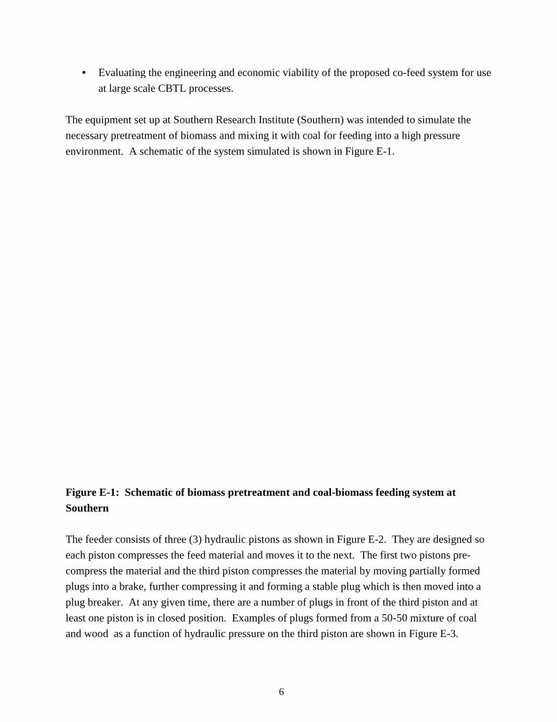
environment. A schematic of the system simulated is shown in Figure E
Figure E-1: Schematic of biomass pretreatment and coalSouthern The feeder consists of three (3) hydraulic piston
each piston compresses the feed material and moves it to the next. The first two pistons pre
compress the material and the third piston compresses the materia
plugs into a brake, further compressing it and forming a stable plug which is then moved into a
plug breaker. At any given time, there are a number of plugs in front of the third piston and at
least one piston is in closed position.
and wood as a function of hydraulic pressure on the third piston are shown in Figure E
6
Evaluating the engineering and economic viability of the proposed co-feed
large scale CBTL processes.
The equipment set up at Southern Research Institute (Southern) was intended to simulate the
ssary pretreatment of biomass and mixing it with coal for feeding into a high pressure
environment. A schematic of the system simulated is shown in Figure E-1.
Schematic of biomass pretreatment and coal-biomass feeding system at
The feeder consists of three (3) hydraulic pistons as shown in Figure E-2. They are designed so
each piston compresses the feed material and moves it to the next. The first two pistons pre
compress the material and the third piston compresses the material by moving partially formed
plugs into a brake, further compressing it and forming a stable plug which is then moved into a
plug breaker. At any given time, there are a number of plugs in front of the third piston and at
ition. Examples of plugs formed from a 50-50 mixture of coal
and wood as a function of hydraulic pressure on the third piston are shown in Figure E
feed system for use
was intended to simulate the
ssary pretreatment of biomass and mixing it with coal for feeding into a high pressure
biomass feeding system at
. They are designed so
each piston compresses the feed material and moves it to the next. The first two pistons pre-
l by moving partially formed
plugs into a brake, further compressing it and forming a stable plug which is then moved into a
plug breaker. At any given time, there are a number of plugs in front of the third piston and at
50 mixture of coal
and wood as a function of hydraulic pressure on the third piston are shown in Figure E-3.

7
Figure E-2. Feeder showing the hopper, pistons, plug transfer to breaker and feed opening from breaker to pressure tank.
Figure E-3. Coal-wood plugs formed after the third piston at hydraulic pressures from 1200-2000 psi The plugs at 1600 psi and higher hydraulic pressure had sufficient integrity and strength to seal
against back pressures up to 500 psi or higher. Based on this finding, a number of runs of the
feeder were conducted at back pressures up to 450 psi.
8
The most important results obtained in the project included:
• Coal-biomass mixtures consisting of 50 to 70 % bituminous coal and lignite mixed with woody biomass, corn stover, and switch grass were successfully prepared using a hammer mill. The size distribution and moisture content of these mixtures was measured.
• Feeder was demonstrated for feeding coal-biomass mixtures containing 50-70 % coal into a high pressure tank at 350-450 psig at variable speeds from 1 to 220 lb/h.
Based on the successful high pressure testing results, the potential advantages of the piston-plug
feeder technology are summarized below:
• The piston-plug feeder technology does not require the use of expensive lock-hopper
systems
• Bridging is not a major issue as in lock-hoppers because the feed hoppers are at low
pressure
• Biomass/coal plugs of sufficient strength and density can be formed using a hydraulic
pressure of 1600-2000 psi on the third piston.
• Biomass aids in the binding--no external binders are used.
Some limitations of the feeder technology that were brought to light during the high pressure
tests included:
• The in-homogeneity of coal-biomass mixtures caused by particle size differences
between coal and biomass and the much lower compressibility and higher density of coal
as opposed to biomass can contribute to segregation in the feed hopper that leads to non-
uniform plug formation. When this happened, the plugs were not able to hold the high
pressure.
• A seal only at the plug needs to be proven safe for use in a combustible environment
such as an entrained flow gasifier—based on a process hazard assessment carried out at
Southern, it was concluded that the feeder would need modification to provide a
secondary seal at the piston.
• Due to potential high power consumption and the sealing problem mentioned above,
TKEnergi has discontinued the scale up of the feeder, thus rendering a detailed economic
evaluation to be of little value.
TKEnergi is currently developing a feeder that seals at the pistons, does not require that the
mixture be uniform, does not require forming and pushing plugs, and thus requires less energy to

9
operate. Southern and TKEnergi are presently discussing the potential development and testing
of this new feeder in a future project.
To summarize the project at Southern,
• Biomass pretreatment system consisting of a fluidized-bed dryer and shredder and
capable of processing up to 500 lb/h biomass, was commissioned at Southern
• Coal-biomass mixtures consisting of 50 to 70 % bituminous coal and lignite mixed with
woody biomass, corn stover, and switch grass were successfully prepared using a
hammer mill.
• TKEnergi Feeder was demonstrated for feeding a coal biomass mixtures containing
greater than 50% coal into a high pressure tank at 350-450 psig at variable speeds from
25 to 220 lb/h.
• The piston-plug feeder needs to be modified to provide a secondary seal at the piston in
addition to the seal formed by the plug.
• TKEnergi is developing a new feeder that
• does not require the formation of plugs
• uses significantly less energy than the present piston-plug feeder design
• Southern and TKEnergi are presently discussing the potential development and
testing of this new feeder.
10
Introduction and Background Due to a finite petroleum resource and increased risk of supply disruption, alternative non-
petroleum sources for transportation fuels need to be developed. Coal and biomass are two of the
most plausible alternative fuels for replacing petroleum as a source of transportation fuels [1].
However, a number of technical barriers need to be overcome to make transportation fuels from
coal and biomass competitive with those from petroleum. These include, among several others,
a lack of biomass to liquids (BTL) and CBTL integrated demonstration, availability of a cost-
effective and reliable feeder for coal-biomass mixtures into high-pressure gasifiers, and high cost
associated with cleanup of syngas from gasifiers to levels suitable for fuel synthesis. Southern has a number of ongoing pilot-scale projects that address these important barriers to
widespread deployment of technologies for converting coal and biomass to liquid transportation
fuels.
Examples of these projects include:
• Fully integrated gasification-based thermochemical biorefinery
• Fuel preparation and feeder for coal and biomass mixtures
• Municipal solid waste conversion to mixed alcohols
• Advanced syngas cleaning and tar reforming system
• Cellulosic biomass hydrolysis to industrial sugars
The total US oil consumption is about 21 million barrels/day (Mbpd). About 14 Mbpd is used in
the transportation sector with light duty vehicles accounting for about 9 Mbpd (138 billion
gallons/year) [2]. Oil resources are finite and alternative energy sources need to be developed.
US imports about 10 million barrels of oil each day, and 65 % of the 10 Mbpd (or 6.5 Mbpd) is
imported from OPEC and Persian Gulf countries. These sources present significant risk of
supply disruption and threaten the energy security of the nation. To improve energy security and
reduce costs, the U.S. Air Force has set a goal to supply 50% of its fuel requirements in the lower
48 States from domestic synthetic sources by 2016 [ 3]. At the same time, the U.S. Department
of the Defense desires to improve its environmental performance and is exploring options to
reduce carbon emissions of the plants producing synthetic fuels to less than that of a
conventional petroleum refinery on an energy content basis.
As an alternative to oil, the US has an abundant supply of proven coal reserves that can last for
over 100 years. The infrastructure for coal mining and supply is quite good because of its
significant use to produce electricity. Coal is also competitive in price but increasing its use for
11
converting coal to liquids (CTL) in addition to electricity is not sustainable due to increased CO2
emissions that contribute to global climate change. Social acceptance is also an issue with
increased coal use due to increased mining operations.
Compared to coal, biomass, an abundant resource, is a renewable CO2 neutral fuel. A major
barrier to increasing the use of biomass in BTL plants is the poor to non-existent infrastructure
for harvesting and transporting biomass for large scale use. There is also the food versus fuel
debate with the use of biomass that can be used for food. Due to these reasons, the availability
of cellulosic (non-food) biomass or waste biomass for BTL plants is neither cheap nor abundant
in a practical sense. It is estimated that with modern cultivating and harvesting techniques,
sustainable cellulosic biomass resource can be increased to 550 million tons/year by 2020 [1].
CTL has been commercially available via the gasification/Fischer-Tropsch (FT) route for over 55
years. However, there are no commercial plants that make fuels and chemicals from coal in the
US (except Eastman’s coal to chemicals complex in Kingsport). This is due to a combination of
several reasons including economics with respect to petroleum, high capital costs involved, and
environmental and social acceptance. CTL can be commercially deployed but will not be until
large scale carbon capture and storage (CCS) is commercially demonstrated.
There are no commercial BTL plants operating in the US. The Energy Independence and
Security Act (EISA) of 2007 mandates increasing renewable fuels from sources such as biomass
nearly 10-fold to >2.3 million barrels per day by 2022. This act has led to significant ongoing
funding by the U.S. Department of Energy to promote biomass to liquids (BTL) research,
development, and demonstration. BTL plants may require significant Government incentives for
CO2 reductions before any private companies assume the risks to build them.
Nonetheless, liquid fuels from biomass and coal have the potential to reduce petroleum fuel use
and CO2 emissions in the U.S. transportation sector over the next 25 years according to a recent
study by the National Research Council [1]. According to the report, “A program of aggressive
support for establishment of first-mover commercial coal-to-liquid transportation fuel plants and
coal-and-biomass-to-liquid (CBTL) transportation-fuel plants with integrated geologic CO2
storage will have to be undertaken immediately if commercial plants are to be deployed by 2020
to address U.S. energy security concerns and to provide fuels whose levels of greenhouse gas
emissions are similar to or less than that of petroleum-based fuels.” A DOE published report
indicates that with a minimum of 8 % by weight biomass feed and with CO2 sequestration,
CBTL process can produce fuels which are economically completive at crude prices above $93
12
per barrel and which have 20% lower Green House Gas (GHG) emissions than petroleum fuel
[4].
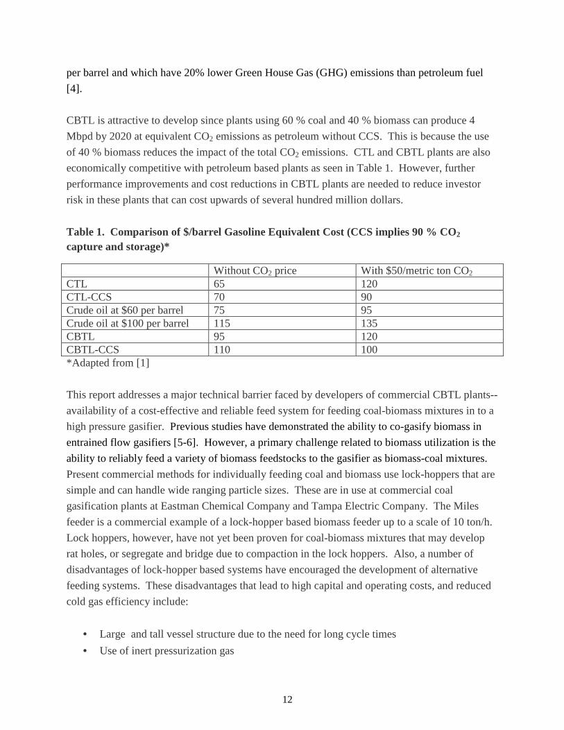
CBTL is attractive to develop since plants using 60 % coal and 40 % biomass can produce 4
Mbpd by 2020 at equivalent CO2 emissions as petroleum without CCS. This is because the use
of 40 % biomass reduces the impact of the total CO2 emissions. CTL and CBTL plants are also
economically competitive with petroleum based plants as seen in Table 1. However, further
performance improvements and cost reductions in CBTL plants are needed to reduce investor
risk in these plants that can cost upwards of several hundred million dollars.
Table 1. Comparison of $/barrel Gasoline Equivalent Cost (CCS implies 90 % CO2 capture and storage)*
Without CO2 price With $50/metric ton CO2 CTL 65 120 CTL-CCS 70 90 Crude oil at $60 per barrel 75 95 Crude oil at $100 per barrel 115 135 CBTL 95 120 CBTL-CCS 110 100 *Adapted from [1]
This report addresses a major technical barrier faced by developers of commercial CBTL plants--
availability of a cost-effective and reliable feed system for feeding coal-biomass mixtures in to a
high pressure gasifier. Previous studies have demonstrated the ability to co-gasify biomass in
entrained flow gasifiers [5-6]. However, a primary challenge related to biomass utilization is the
ability to reliably feed a variety of biomass feedstocks to the gasifier as biomass-coal mixtures.
Present commercial methods for individually feeding coal and biomass use lock-hoppers that are
simple and can handle wide ranging particle sizes. These are in use at commercial coal
gasification plants at Eastman Chemical Company and Tampa Electric Company. The Miles
feeder is a commercial example of a lock-hopper based biomass feeder up to a scale of 10 ton/h.
Lock hoppers, however, have not yet been proven for coal-biomass mixtures that may develop
rat holes, or segregate and bridge due to compaction in the lock hoppers. Also, a number of
disadvantages of lock-hopper based systems have encouraged the development of alternative
feeding systems. These disadvantages that lead to high capital and operating costs, and reduced
cold gas efficiency include:
• Large and tall vessel structure due to the need for long cycle times
• Use of inert pressurization gas
13
• Significant loss of cold gas efficiency above 500 psig
• Non-continuous feed
• Poor lock valve reliability with wet-dusty feed
The disadvantages of lock hoppers have encouraged the development of feeders that work like
solids pump rather than use an inert high pressure gas for maintaining front pressure and pushing
the solids into the high pressure gasifier [5-10]. Some feeders of the past that do not require lock
hoppers such as the K-Tron pump and the Walden diaphragm pump however could not build
sufficient pressure, and some did not work well for coal such as the Foster Miller Linear Pocket
Feeder. Currently, as far as we know, only the General Electric’s Stamet Posimetric Pump, the
Pratt-Whitney Rocketdyne (PWR) Pump, and the TKEnergi (Southern’s partner in this project)
Piston-Plug feeder are under development. These systems have been under development for
several years but have not reached full commercialization status.
The TKEnergi system chosen for this work has been demonstrated at a large pilot scale for
biomass, but not for coal-biomass mixtures. It has been demonstrated at a scale of up to 6
ton/day biomass for feeding against pressures up to 450 psig. There is potential for the feeder to
be able to feed coal biomass mixtures because biomass can potentially act as a binder of the coal
particles. In this report, the testing of a 250 lb/h high pressure pilot-scale feeder designed and
provided by TKEnergi to Southern is described. The feeder technology from TKEnergi based on
3 pistons operating in sequence is an alternative to expensive and bulky lock hopper systems.
The aim of the project is to demonstrate cost effective feeding of coal-biomass mixtures (50:50
to 70:30) made from a variety of coals (bituminous, lignite) and biomass (woody, corn stover,
switch grass) against pressures up to 450 psig.
Objectives The goal of this project is to design and demonstrate the operability of a biomass pretreatment
and a coal/biomass co-feed system. The system will be examined for use with high pressure,
commercial-scale entrained gasification systems utilized in future large scale coal and biomass to
liquids (CBTL) facilities. Specific objectives include:
• Specifying an appropriate biomass pretreatment system,
• Demonstrating the ability of this pretreatment system and a commercially-available feed
system proven for biomass to co-feed a variety of biomass and coal mixtures into a
simulated high pressure environment similar to that encountered in CBTL facilities, and

• Evaluating the engineering and economic viability of the proposed
at large scale CBTL processe
The commercially-available feed system chosen for this project was a
feeder system from Denmark’s TK
least 50 weight % coal and up to 70 % coal
been proven at 450 psig for up to 6 ton/day scale for biomass.
Equipment Description
The equipment at Southern is intended to simulate the necessary pretreatment of biomass and
mixing it with coal for feeding into a high pressure
simulated is shown in Figure 1. Depending on the properties of the biomass and the state of the
received coal, the type and sequence
Figure 1: Schematic of biomass pretreatment and
14
Evaluating the engineering and economic viability of the proposed co-feed
large scale CBTL processes.
available feed system chosen for this project was a 250 lb/h piston
feeder system from Denmark’s TKEnergi for feeding a variety of biomass/coal mixtures with at
and up to 70 % coal into a high pressure environment. This system has
to 6 ton/day scale for biomass.
thern is intended to simulate the necessary pretreatment of biomass and
mixing it with coal for feeding into a high pressure environment. A schematic of the system
is shown in Figure 1. Depending on the properties of the biomass and the state of the
sequence of steps may change.
Schematic of biomass pretreatment and coal-biomass feeding system at S
feed system for use
250 lb/h piston-plug
for feeding a variety of biomass/coal mixtures with at
. This system has
thern is intended to simulate the necessary pretreatment of biomass and
environment. A schematic of the system
is shown in Figure 1. Depending on the properties of the biomass and the state of the
biomass feeding system at Southern
15
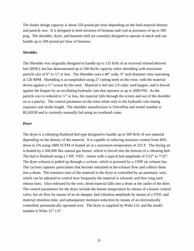
The feeder design capacity is about 250 pound per hour depending on the feed material density
and particle size. It is designed to feed mixtures of biomass and coal at pressures of up to 500
psig. The shredder, dryer, and hammer mill are currently designed to operate in batch and can
handle up to 500 pound per hour of biomass.
Shredder
The Shredder was originally designed to handle up to 135 lb/hr of as received refused derived
fuel (RDF), but has demonstrated up to 500 lbs/hr capacity when shredding with maximum
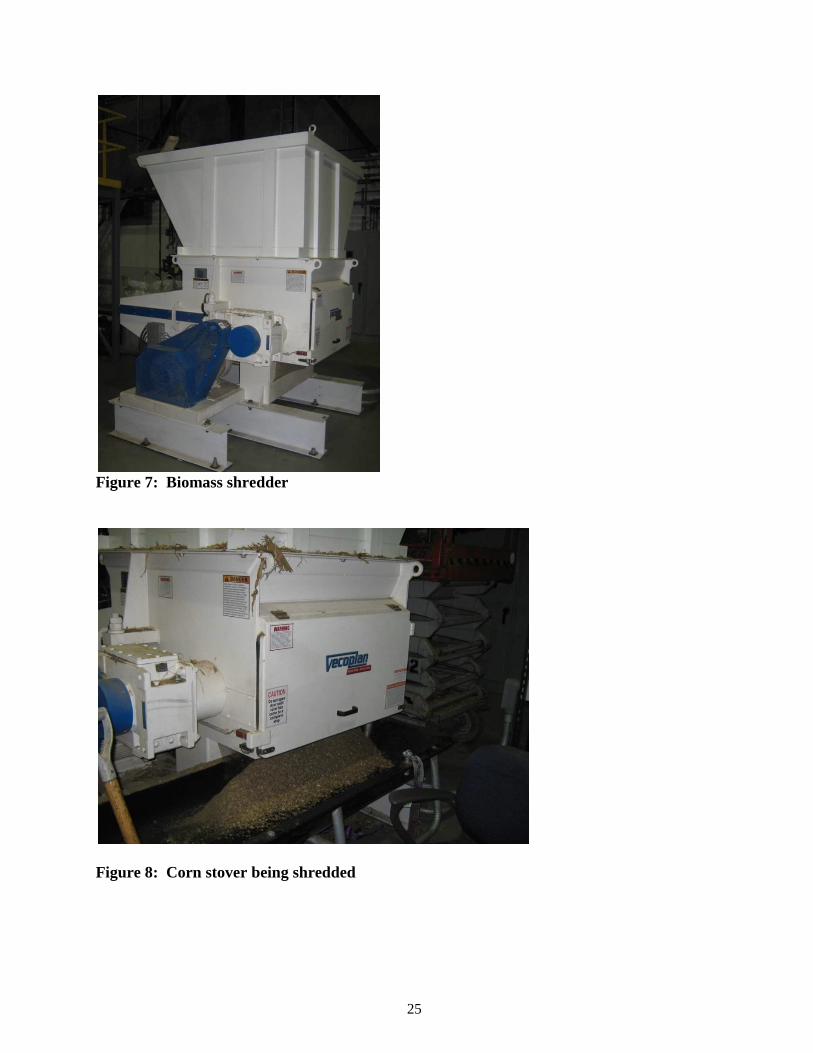
particle size of 6” to ½” or less. The Shredder uses a 48” wide, 9” inch diameter rotor operating
at 120 RPM. Shredding is accomplished using 27 cutting teeth on the rotor, with the material
driven against a ½” screen by the rotor. Material is fed into 2.9 cubic yard hopper, and is forced
against the hopper by an oscillating hydraulic ram that operates at up to 2600 PSI. As the
particle size is reduced to ½” or less, the material falls through the screen and out of the shredder
on to a pan/try. The control parameter on the rotor relate only to the hydraulic ram timing
sequence and stroke length. The shredder manufacturer is VelcoPlan and model number is
RG42030 and is currently manually fed using an overhead crane.
Dryer
The dryer is a vibrating fluidized bed type designed to handle up to 500 lb/hr of wet material
depending on the density of the material. It is capable of reducing moisture content from 40%
down to 5% using 1800 SCFM of heated air at a maximum temperature of 325 F. The drying air
is heated by a 500,000 Btu natural gas burner, which is forced into the bottom of a vibrating bed.
The bed is fluidized using a 1 HP, VFD – motor with a typical bed amplitude of 5/32” to 7/32”.
The dryer exhaust is pulled up through a cyclone, which is powered by a 15HP air exhaust fan.
The cyclone captures particulates that become entrained in the exhaust flow and collects them
into a drum. The retention time of the material in the dryer is controlled by an automatic weir,
which can be adjusted to control how frequently the material is released, and how long each
release lasts. Once released by the weir, dried material falls into a drum at the outlet of the drier.
The control parameters for the dryer include the burner temperature by means of a burner control
valve, hot air flow by means of an air damper, bed vibration amplitude by means of a VFD, and
material retention time, and subsequence moisture reduction by means of an electronically
controlled, pneumatically operated weir. The dryer is supplied by Witte CO. and the model
number is Witte 12” x 6”.
16
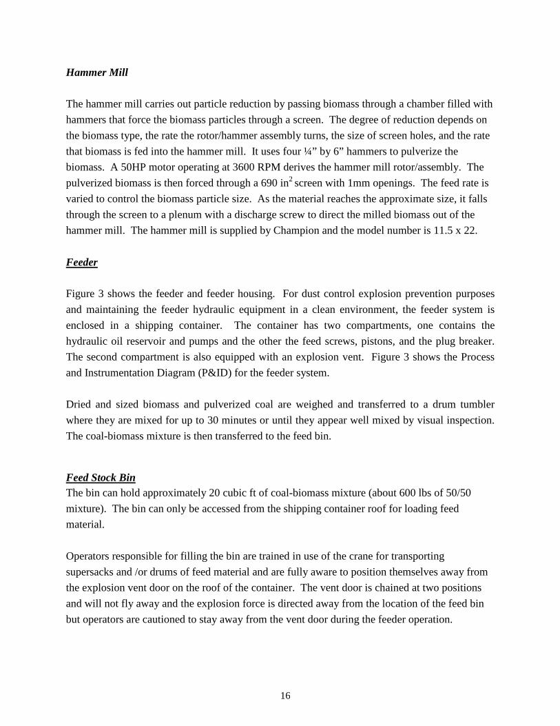
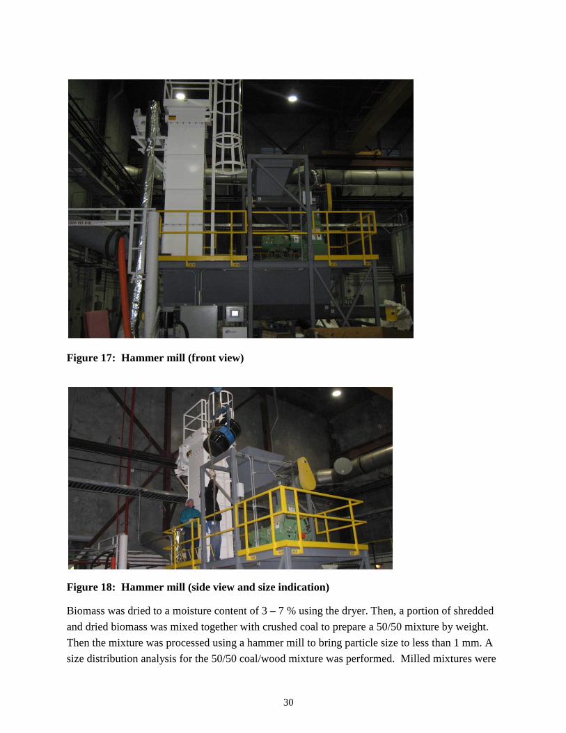
Hammer Mill
The hammer mill carries out particle reduction by passing biomass through a chamber filled with
hammers that force the biomass particles through a screen. The degree of reduction depends on
the biomass type, the rate the rotor/hammer assembly turns, the size of screen holes, and the rate
that biomass is fed into the hammer mill. It uses four ¼” by 6” hammers to pulverize the
biomass. A 50HP motor operating at 3600 RPM derives the hammer mill rotor/assembly. The
pulverized biomass is then forced through a 690 in2 screen with 1mm openings. The feed rate is
varied to control the biomass particle size. As the material reaches the approximate size, it falls
through the screen to a plenum with a discharge screw to direct the milled biomass out of the
hammer mill. The hammer mill is supplied by Champion and the model number is 11.5 x 22.
Feeder
Figure 3 shows the feeder and feeder housing. For dust control explosion prevention purposes
and maintaining the feeder hydraulic equipment in a clean environment, the feeder system is
enclosed in a shipping container. The container has two compartments, one contains the
hydraulic oil reservoir and pumps and the other the feed screws, pistons, and the plug breaker.
The second compartment is also equipped with an explosion vent. Figure 3 shows the Process
and Instrumentation Diagram (P&ID) for the feeder system.
Dried and sized biomass and pulverized coal are weighed and transferred to a drum tumbler
where they are mixed for up to 30 minutes or until they appear well mixed by visual inspection.
The coal-biomass mixture is then transferred to the feed bin.
Feed Stock Bin The bin can hold approximately 20 cubic ft of coal-biomass mixture (about 600 lbs of 50/50
mixture). The bin can only be accessed from the shipping container roof for loading feed
material.
Operators responsible for filling the bin are trained in use of the crane for transporting
supersacks and /or drums of feed material and are fully aware to position themselves away from
the explosion vent door on the roof of the container. The vent door is chained at two positions
and will not fly away and the explosion force is directed away from the location of the feed bin
but operators are cautioned to stay away from the vent door during the feeder operation.
17
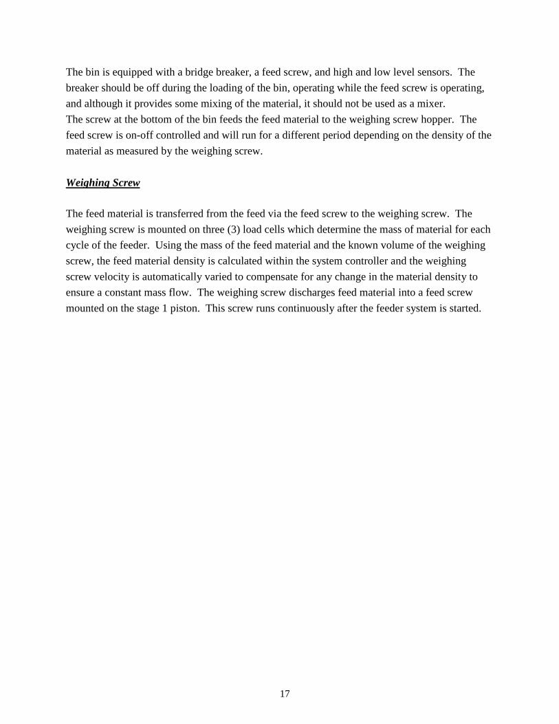
The bin is equipped with a bridge breaker, a feed screw, and high and low level sensors. The
breaker should be off during the loading of the bin, operating while the feed screw is operating,
and although it provides some mixing of the material, it should not be used as a mixer.
The screw at the bottom of the bin feeds the feed material to the weighing screw hopper. The
feed screw is on-off controlled and will run for a different period depending on the density of the
material as measured by the weighing screw.
Weighing Screw
The feed material is transferred from the feed via the feed screw to the weighing screw. The
weighing screw is mounted on three (3) load cells which determine the mass of material for each
cycle of the feeder. Using the mass of the feed material and the known volume of the weighing
screw, the feed material density is calculated within the system controller and the weighing
screw velocity is automatically varied to compensate for any change in the material density to
ensure a constant mass flow. The weighing screw discharges feed material into a feed screw
mounted on the stage 1 piston. This screw runs continuously after the feeder system is started.
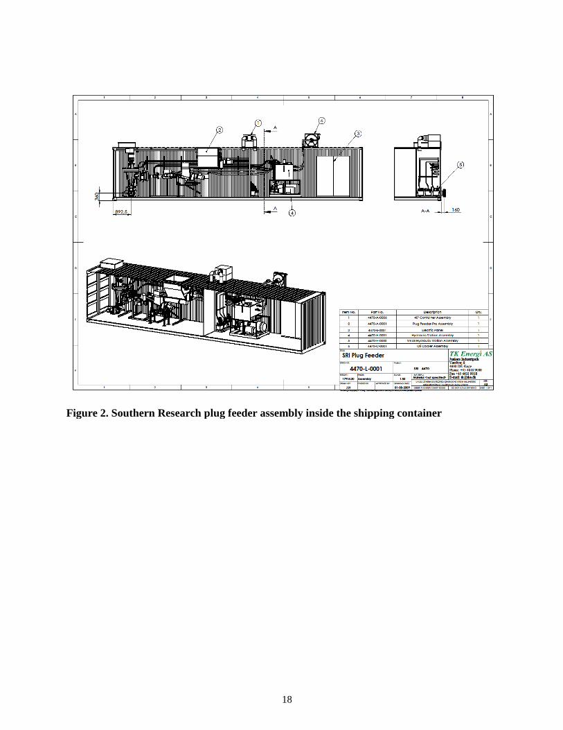
Figure 2. Southern Research plug feeder assembly inside the shipping container
18
Figure 2. Southern Research plug feeder assembly inside the shipping container
Figure 2. Southern Research plug feeder assembly inside the shipping container
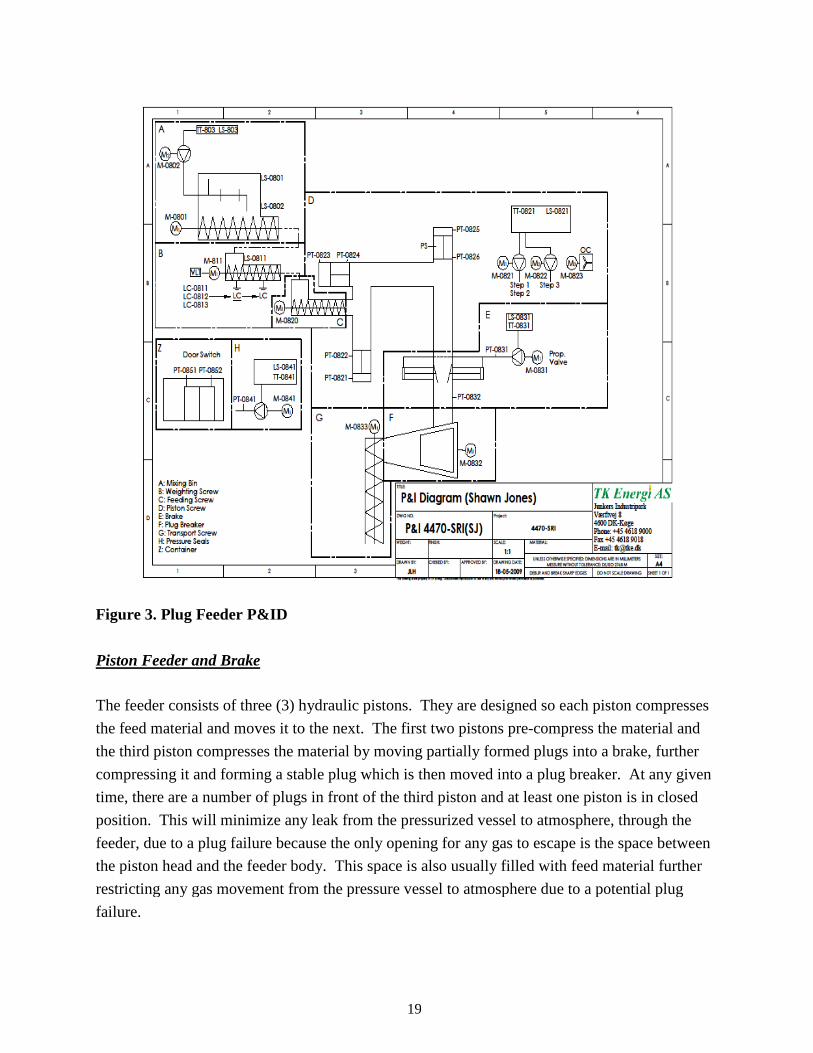
Figure 3. Plug Feeder P&ID Piston Feeder and Brake
The feeder consists of three (3) hydraulic piston
the feed material and moves it to the next. The first two pistons pre
the third piston compresses the material by moving partially formed plugs into a brake, further
compressing it and forming a stable plug which is then moved into a plug breaker. At any given
time, there are a number of plugs in front of the third piston and at least one p
position. This will minimize any leak from the pressurized vessel to atmosphere, through the
feeder, due to a plug failure because the only opening for any gas to escape is the space between
the piston head and the feeder body. This sp
restricting any gas movement from the pressure vessel to atmosphere due to a potential plug
failure.
19
The feeder consists of three (3) hydraulic pistons. They are designed so each piston compresses
the feed material and moves it to the next. The first two pistons pre-compress the material and
compresses the material by moving partially formed plugs into a brake, further
compressing it and forming a stable plug which is then moved into a plug breaker. At any given
time, there are a number of plugs in front of the third piston and at least one piston is in close
any leak from the pressurized vessel to atmosphere, through the
feeder, due to a plug failure because the only opening for any gas to escape is the space between
the piston head and the feeder body. This space is also usually filled with feed material further
restricting any gas movement from the pressure vessel to atmosphere due to a potential plug
. They are designed so each piston compresses
compress the material and
compresses the material by moving partially formed plugs into a brake, further
compressing it and forming a stable plug which is then moved into a plug breaker. At any given
iston is in closed
any leak from the pressurized vessel to atmosphere, through the
feeder, due to a plug failure because the only opening for any gas to escape is the space between
with feed material further
restricting any gas movement from the pressure vessel to atmosphere due to a potential plug

20
The hydraulic pressure exerted on each piston is measured in forward and reverse positions. The
first and second piston always move from end to end while the third piston is moved back and
forth to positions determined by the properties (i.e., density) of the material being fed.
The plug brake is mounted directly to the feeder body. It is used to control the movement of the
plug. The brake consists of three jaws, one fixed and two that are used to hold, compress, and
release the plug. The density of the plug is adjusted to a pre-established desired value by the
force exerted on the pistons acting on the two brake-jaws. A hydraulic valve is used to control
the pressure on these pistons. The position of the fixed jaw can be changed manually if desired
or if required due to wear of the jaws.
Plug Breaker
The plug breaker is placed directly after the brake. A rotating drum, inside the breaker housing,
tears the plug apart to pieces manageable by the transport. A section of the transport screw is
placed directly below the rotating drum, directing material down into the transport screw. The
drum can be adjusted up and down in order to compensate for wear and to adjust the particle size
of the material leaving the plug breaker. The breaker typically breaks-up the plug and reduces
the particle size to its original size. However, since the feeder is a used feeder and the objective
of this project was not to show actual operation in a entrained flow gasifier but to demonstrate
that the pressure barrier can be overcome, the breaker was not redesigned and replaced in this
phase of the project.
Transport Screw
The transport screw feeds the material from the bottom of the plug breaker into the pressure
vessel located outside of the container. The transport screw housing has been pressure tested at
725 psi and the manufacture’s recommended maximum operating pressure 505 psi.
Pressure Seals
The plug breaker and transport screw are both equipped with stationary double pressure balanced
mechanical seals. Pressure on the barrier fluid is upheld by a hydraulic power pack.
21
Pressure Vessel
The pressure vessel is designed to operate at up to 600 psig at temperatures of up to 120o F.
Nitrogen is used to pressurize the vessel to about 500 psig before biomass-coal mixture is fed
into the vessel. As material is fed into the vessel and replaces the nitrogen volume, a pressure
control valve will release nitrogen to maintain the vessel pressure. The pressure vessel is also
equipped with pressure and temperature indicators for analytical purposes. A pressure
transmitter will pause the feeder in case the system pressure exceeds 501 psi. For personnel
safety and protection of equipment, a rupture disc set at 600 psig will protect the pressure vessel
from any accidental pressurization beyond its design capabilities. The pressure vessel is designed
to hold feed material for up to four hours of continuous feeding, depending on the material
density. A level switch will pause the feeder to prevent the vessel from overfilling. Overfilling
the vessel could interfere with the operation of the transport screw feeder and cause plugging of
the feed line. The vessel is also designed to allow injection of inert detectable gases. Gas
monitors located within the feeder container at various locations on the feeder system (i.e.,
before and after the break) will be used to detect any gas that may leak from the pressure vessel
into the feeder system.
Experimental The specifications of the biomass pretreatment equipment are provided in Table 2. Fuel
preparation consists of biomass pretreatment and mixing with pulverized coal. As received
biomass is received and transferred to a shredder. The shredded biomass is dried using a
fluidized-bed dryer down to 3-7 % moisture. The sequence depends on the biomass. It has been
found that this sequence works well for woody biomass; whereas drying followed by shredding
works better for stalk and stringy biomasses like corn stover and switch grass. The shredded
biomass is hammered down to less than 1 mm and mixed with the coal in the required proportion
prior to pumping it into the high pressure chamber. This is the sequence to be followed for
lignite as it is received pre-pulverized. On the other hand, the bituminous coal was received as
lumps. So the lumps were broken down to 0.5 to 1 inch sizes and mixed with the shredded
biomass. The hammer mill was used to reduce the size of the mixture to less than 1mm.
22
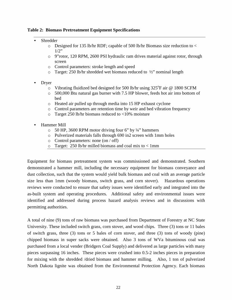
Table 2: Biomass Pretreatment Equipment Specifications
• Shredder o Designed for 135 lb/hr RDF; capable of 500 lb/hr Biomass size reduction to <
1/2” o 9”rotor, 120 RPM, 2600 PSI hydraulic ram drives material against rotor, through
screen o Control parameters: stroke length and speed o Target: 250 lb/hr shredded wet biomass reduced to ½” nominal length
• Dryer
o Vibrating fluidized bed designed for 500 lb/hr using 325oF air @ 1800 SCFM o 500,000 Btu natural gas burner with 7.5 HP blower, feeds hot air into bottom of
bed o Heated air pulled up through media into 15 HP exhaust cyclone o Control parameters are retention time by weir and bed vibration frequency o Target 250 lb/hr biomass reduced to <10% moisture
• Hammer Mill
o 50 HP, 3600 RPM motor driving four 6” by ¼” hammers o Pulverized materials falls through 690 in2 screen with 1mm holes o Control parameters: none (on / off) o Target: 250 lb/hr milled biomass and coal mix to < 1mm
Equipment for biomass pretreatment system was commissioned and demonstrated. Southern
demonstrated a hammer mill, including the necessary equipment for biomass conveyance and
dust collection, such that the system would yield bulk biomass and coal with an average particle
size less than 1mm (woody biomass, switch grass, and corn stover). Hazardous operations
reviews were conducted to ensure that safety issues were identified early and integrated into the
as-built system and operating procedures. Additional safety and environmental issues were
identified and addressed during process hazard analysis reviews and in discussions with
permitting authorities.
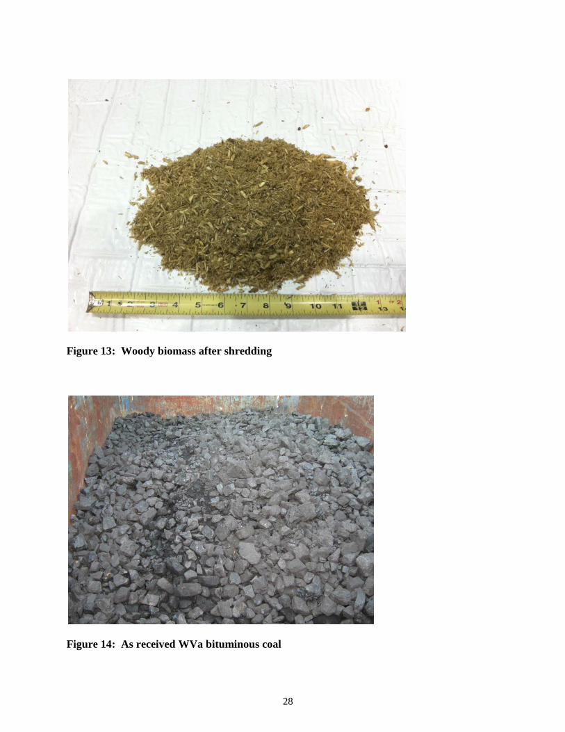
A total of nine (9) tons of raw biomass was purchased from Department of Forestry at NC State
University. These included switch grass, corn stover, and wood chips. Three (3) tons or 11 bales
of switch grass, three (3) tons or 5 bales of corn stover, and three (3) tons of woody (pine)
chipped biomass in super sacks were obtained. Also 3 tons of WVa bituminous coal was
purchased from a local vender (Bridgers Coal Supply) and delivered as large particles with many
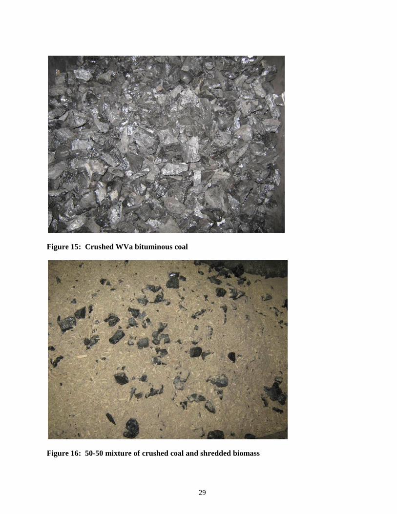
pieces surpassing 16 inches. These pieces were crushed into 0.5-2 inches pieces in preparation
for mixing with the shredded /dried biomass and hammer milling. Also, 1 ton of pulverized
North Dakota lignite was obtained from the Environmental Protection Agency. Each biomass
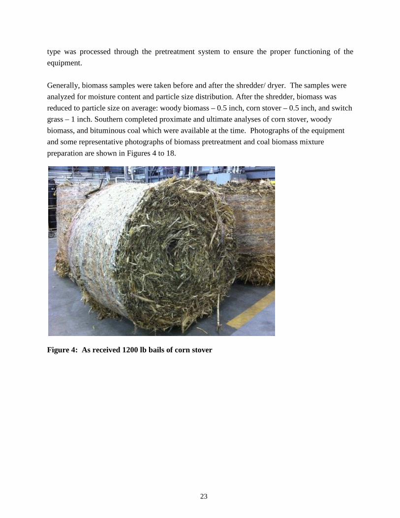
23
type was processed through the pretreatment system to ensure the proper functioning of the
equipment.
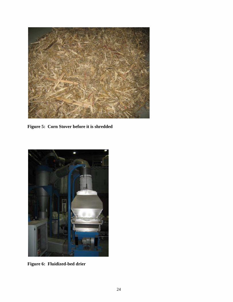
Generally, biomass samples were taken before and after the shredder/ dryer. The samples were
analyzed for moisture content and particle size distribution. After the shredder, biomass was
reduced to particle size on average: woody biomass – 0.5 inch, corn stover – 0.5 inch, and switch
grass – 1 inch. Southern completed proximate and ultimate analyses of corn stover, woody
biomass, and bituminous coal which were available at the time. Photographs of the equipment
and some representative photographs of biomass pretreatment and coal biomass mixture
preparation are shown in Figures 4 to 18.
Figure 4: As received 1200 lb bails of corn stover
24
Figure 5: Corn Stover before it is shredded
Figure 6: Fluidized-bed drier
25
Figure 7: Biomass shredder
Figure 8: Corn stover being shredded
26
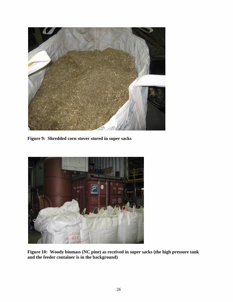
Figure 9: Shredded corn stover stored in super sacks
Figure 10: Woody biomass (NC pine) as received in super sacks (the high pressure tank and the feeder container is in the background)
27
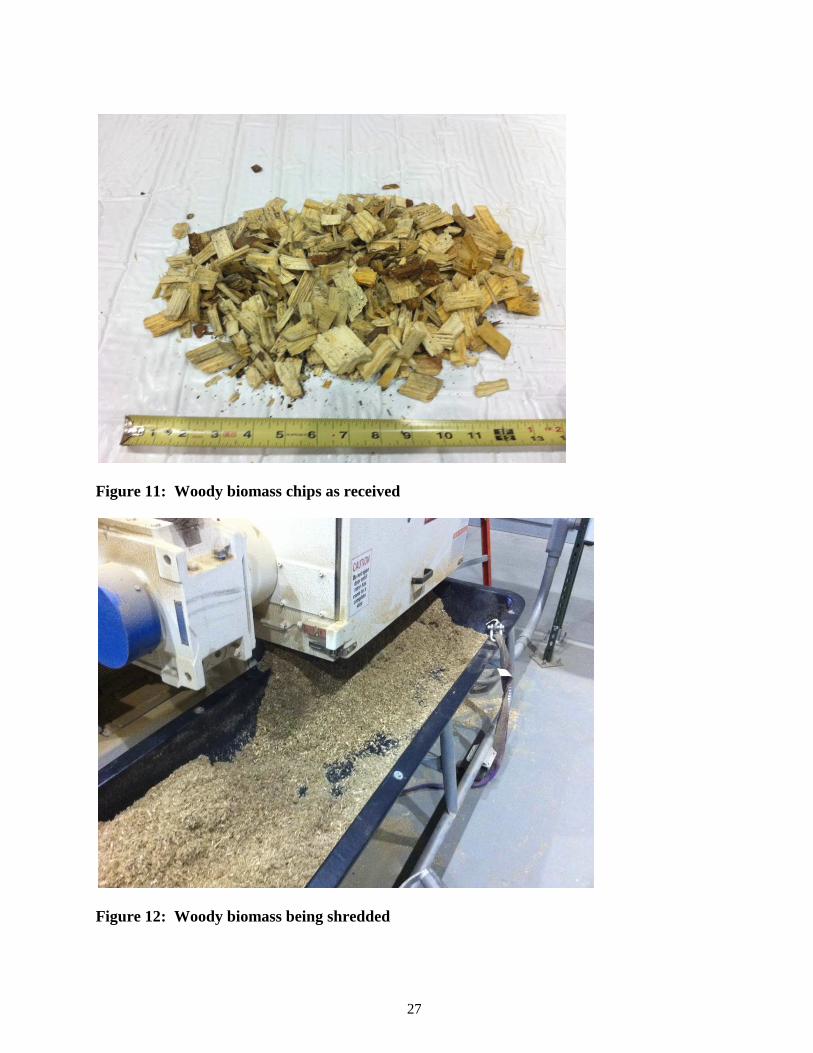
Figure 11: Woody biomass chips as received
Figure 12: Woody biomass being shredded
28
Figure 13: Woody biomass after shredding
Figure 14: As received WVa bituminous coal
29
Figure 15: Crushed WVa bituminous coal
Figure 16: 50-50 mixture of crushed coal and shredded biomass
30
Figure 17: Hammer mill (front view)
Figure 18: Hammer mill (side view and size indication)
Biomass was dried to a moisture content of 3 – 7 % using the dryer. Then, a portion of shredded
and dried biomass was mixed together with crushed coal to prepare a 50/50 mixture by weight.
Then the mixture was processed using a hammer mill to bring particle size to less than 1 mm. A
size distribution analysis for the 50/50 coal/wood mixture was performed. Milled mixtures were
31
stored in 55 gallon drums and sealed in order to protect against moisture. All drums contained
about 120 lb of mixed materials. Bulk density was determined to be 16.3 lb/cf.
Piston-Plug Feeder and Pressure Vessel
The 4.0 inch nominal size piston plug feeder was supplied by TKEnergi from Denmark. It works
on the principle of using three pistons in series in a timed sequence to compress solid particles to
form and move nominally 4.0 inch diameter cylindrical plugs, that form a seal against high back
pressure. The length of the plug depends on the timing between the piston strokes. The plugs
formed first are pushed by the plugs formed later. Eventually the plug enters a plug breaker
where the plug is broken back to particles of original size. These particles are then transported
using a screw conveyor in to a high pressure vessel. The specifications and features of the feeder
are summarized in Table 3.
Table 3: Piston-Plug Feeder Specifications and Features
• 250 lb/hr mass flow, 3-stage piston plug feeder • Biomass / Coal plug in 3rd stage piston provides seal against high pressure environment • ‘Weigh Screw’ located before pistons measures mass flow (screw mounted on load cells) • Plugs created at hydraulic brake on 3rd stage piston
o Plug hardness can be adjusted in feeder controls (increases or decreases hydraulic brake pressure)
o Plug weight can be adjusted in feeder controls ( increases or decreases piston 3 stroke into lump breaker; higher plug weight equates to more mass of a plug sent to lump breaker)
• Plugs crushed for feeding into vessel by plug breaker (‘Lump Breaker’ – vertical grinding block at outlet of 3rd stage piston)
• Feed screw transports crushed material from lump breaker to vessel
As described earlier, the feeder was housed in a 20 ft x 8 ft container, with hydraulics and
electrical equipment on the right and the pistons on the left as was shown earlier in Figure 2.
The system included a day hopper; a multi-piston drive plug feed system, screw feeders, and a
plug breaker. The container was purged and was equipped with dust filters and an explosion
vent.
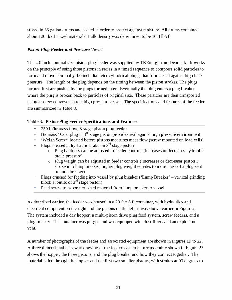
A number of photographs of the feeder and associated equipment are shown in Figures 19 to 22.
A three dimensional cut-away drawing of the feeder system before assembly shown in Figure 23
shows the hopper, the three pistons, and the plug breaker and how they connect together. The
material is fed through the hopper and the first two smaller pistons, with strokes at 90 degrees to
32
each other, bring the material in the path of the third 4 inch piston that then compresses it in to a
plug at a hydraulic brake.
Figure 19: The feeder: hopper, pistons, and transfer screw installed in container
33
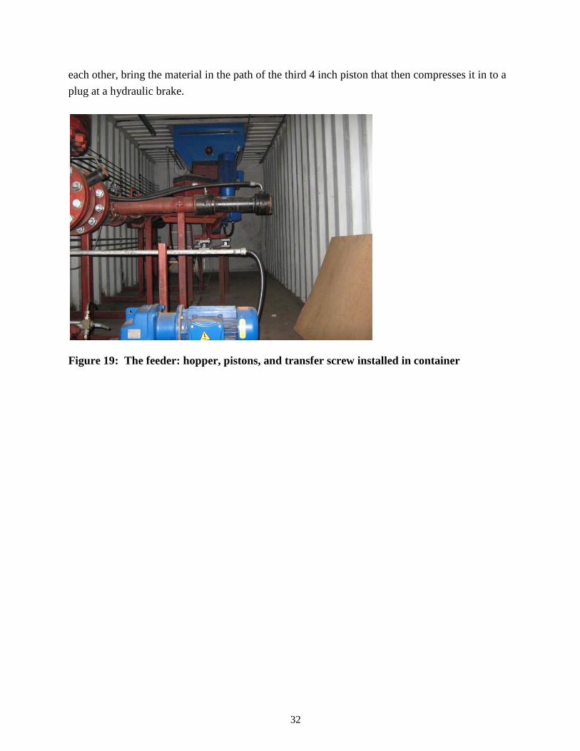
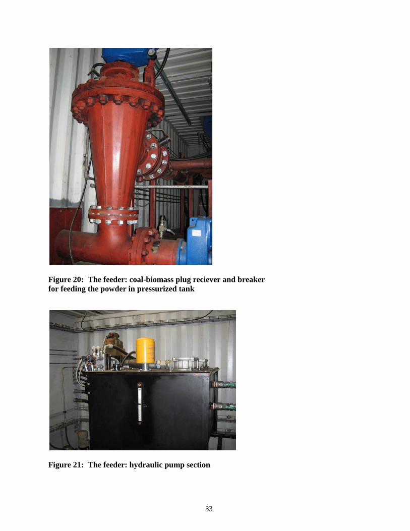
Figure 20: The feeder: coal-biomass plug reciever and breaker for feeding the powder in pressurized tank
Figure 21: The feeder: hydraulic pump section
34
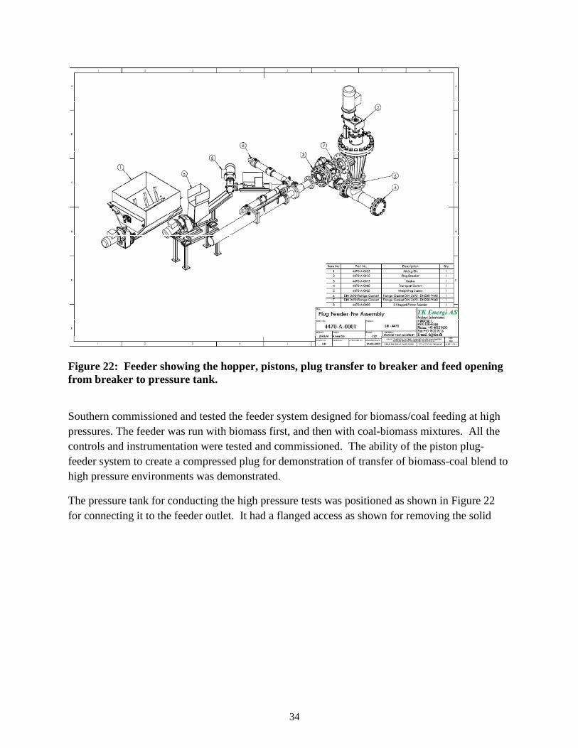
Figure 22: Feeder showing the hopper, pistons, plug transfer to breaker and feed opening from breaker to pressure tank.
Southern commissioned and tested the feeder system designed for biomass/coal feeding at high pressures. The feeder was run with biomass first, and then with coal-biomass mixtures. All the controls and instrumentation were tested and commissioned. The ability of the piston plug-feeder system to create a compressed plug for demonstration of transfer of biomass-coal blend to high pressure environments was demonstrated.
The pressure tank for conducting the high pressure tests was positioned as shown in Figure 22 for connecting it to the feeder outlet. It had a flanged access as shown for removing the solid
35
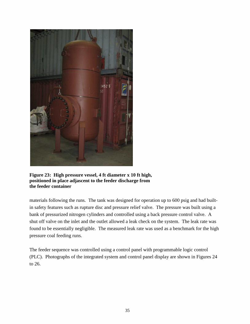
Figure 23: High pressure vessel, 4 ft diameter x 10 ft high, positioned in place adjascent to the feeder discharge from the feeder container
materials following the runs. The tank was designed for operation up to 600 psig and had built-
in safety features such as rupture disc and pressure relief valve. The pressure was built using a
bank of pressurized nitrogen cylinders and controlled using a back pressure control valve. A
shut off valve on the inlet and the outlet allowed a leak check on the system. The leak rate was
found to be essentially negligible. The measured leak rate was used as a benchmark for the high
pressure coal feeding runs.
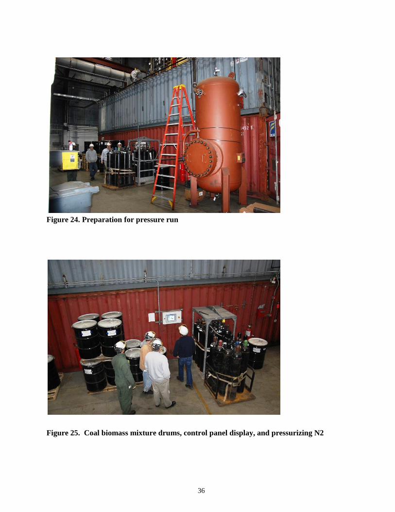
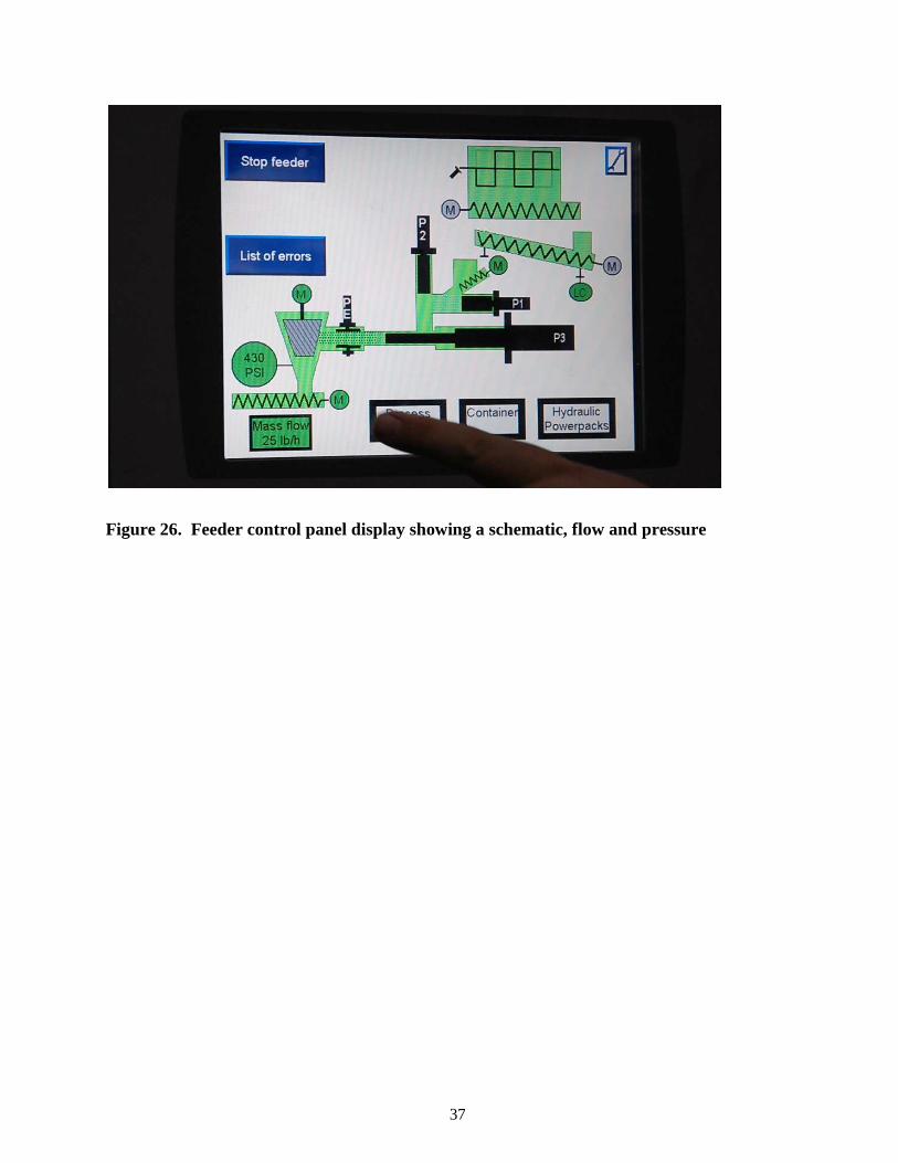
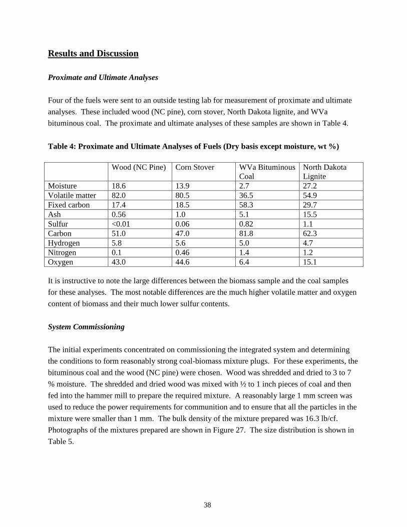
The feeder sequence was controlled using a control panel with programmable logic control
(PLC). Photographs of the integrated system and control panel display are shown in Figures 24
to 26.
36
Figure 24. Preparation for pressure run
Figure 25. Coal biomass mixture drums, control panel display, and pressurizing N2
37
Figure 26. Feeder control panel display showing a schematic, flow and pressure
38
Results and Discussion Proximate and Ultimate Analyses
Four of the fuels were sent to an outside testing lab for measurement of proximate and ultimate
analyses. These included wood (NC pine), corn stover, North Dakota lignite, and WVa
bituminous coal. The proximate and ultimate analyses of these samples are shown in Table 4.
Table 4: Proximate and Ultimate Analyses of Fuels (Dry basis except moisture, wt %) Wood (NC Pine) Corn Stover WVa Bituminous
Coal North Dakota Lignite
Moisture 18.6 13.9 2.7 27.2 Volatile matter 82.0 80.5 36.5 54.9 Fixed carbon 17.4 18.5 58.3 29.7 Ash 0.56 1.0 5.1 15.5 Sulfur <0.01 0.06 0.82 1.1 Carbon 51.0 47.0 81.8 62.3 Hydrogen 5.8 5.6 5.0 4.7 Nitrogen 0.1 0.46 1.4 1.2 Oxygen 43.0 44.6 6.4 15.1 It is instructive to note the large differences between the biomass sample and the coal samples
for these analyses. The most notable differences are the much higher volatile matter and oxygen
content of biomass and their much lower sulfur contents.
System Commissioning
The initial experiments concentrated on commissioning the integrated system and determining
the conditions to form reasonably strong coal-biomass mixture plugs. For these experiments, the
bituminous coal and the wood (NC pine) were chosen. Wood was shredded and dried to 3 to 7
% moisture. The shredded and dried wood was mixed with ½ to 1 inch pieces of coal and then
fed into the hammer mill to prepare the required mixture. A reasonably large 1 mm screen was
used to reduce the power requirements for communition and to ensure that all the particles in the
mixture were smaller than 1 mm. The bulk density of the mixture prepared was 16.3 lb/cf.
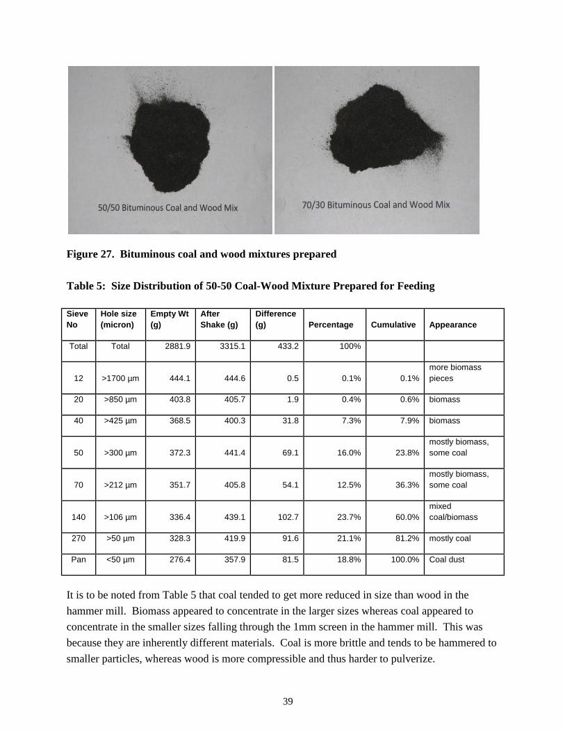
Photographs of the mixtures prepared are shown in Figure 27. The size distribution is shown in
Table 5.
39
Figure 27. Bituminous coal and wood mixtures prepared Table 5: Size Distribution of 50-50 Coal-Wood Mixture Prepared for Feeding Sieve No
Hole size (micron)
Empty Wt (g)
After Shake (g)
Difference (g) Percentage Cumulative Appearance
Total Total 2881.9 3315.1 433.2 100%
12 >1700 µm 444.1 444.6 0.5 0.1% 0.1% more biomass pieces
20 >850 µm 403.8 405.7 1.9 0.4% 0.6% biomass
40 >425 µm 368.5 400.3 31.8 7.3% 7.9% biomass
50 >300 µm 372.3 441.4 69.1 16.0% 23.8% mostly biomass, some coal
70 >212 µm 351.7 405.8 54.1 12.5% 36.3% mostly biomass, some coal
140 >106 µm 336.4 439.1 102.7 23.7% 60.0% mixed coal/biomass
270 >50 µm 328.3 419.9 91.6 21.1% 81.2% mostly coal
Pan <50 µm 276.4 357.9 81.5 18.8% 100.0% Coal dust
It is to be noted from Table 5 that coal tended to get more reduced in size than wood in the
hammer mill. Biomass appeared to concentrate in the larger sizes whereas coal appeared to
concentrate in the smaller sizes falling through the 1mm screen in the hammer mill. This was
because they are inherently different materials. Coal is more brittle and tends to be hammered to
smaller particles, whereas wood is more compressible and thus harder to pulverize.
40
The initial feeder commissioning experiments were of necessity run against ambient pressure
because of a need to collect the plugs. These experiments evaluated plug integrity during feeding
as a function of pump hydraulic pressure. To physically remove and examine a compressed
mixture (plug), it was necessary to remove the plug breaker after the third piston during
operation of the feeder. This allowed direct observation of plug size and density using various
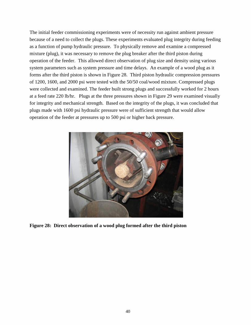
system parameters such as system pressure and time delays. An example of a wood plug as it
forms after the third piston is shown in Figure 28. Third piston hydraulic compression pressures
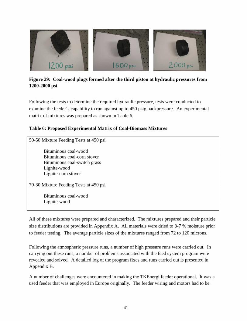
of 1200, 1600, and 2000 psi were tested with the 50/50 coal/wood mixture. Compressed plugs
were collected and examined. The feeder built strong plugs and successfully worked for 2 hours
at a feed rate 220 lb/hr. Plugs at the three pressures shown in Figure 29 were examined visually
for integrity and mechanical strength. Based on the integrity of the plugs, it was concluded that
plugs made with 1600 psi hydraulic pressure were of sufficient strength that would allow
operation of the feeder at pressures up to 500 psi or higher back pressure.
Figure 28: Direct observation of a wood plug formed after the third piston
41
Figure 29: Coal-wood plugs formed after the third piston at hydraulic pressures from 1200-2000 psi
Following the tests to determine the required hydraulic pressure, tests were conducted to
examine the feeder’s capability to run against up to 450 psig backpressure. An experimental
matrix of mixtures was prepared as shown in Table 6.
Table 6: Proposed Experimental Matrix of Coal-Biomass Mixtures 50-50 Mixture Feeding Tests at 450 psi
Bituminous coal-wood Bituminous coal-corn stover Bituminous coal-switch grass Lignite-wood Lignite-corn stover
70-30 Mixture Feeding Tests at 450 psi
Bituminous coal-wood Lignite-wood
All of these mixtures were prepared and characterized. The mixtures prepared and their particle
size distributions are provided in Appendix A. All materials were dried to 3-7 % moisture prior
to feeder testing. The average particle sizes of the mixtures ranged from 72 to 120 microns.
Following the atmospheric pressure runs, a number of high pressure runs were carried out. In carrying out these runs, a number of problems associated with the feed system program were revealed and solved. A detailed log of the program fixes and runs carried out is presented in Appendix B.
A number of challenges were encountered in making the TKEnergi feeder operational. It was a used feeder that was employed in Europe originally. The feeder wiring and motors had to be
42
thus changed for US voltage and frequency. Also a number of undersized electrical components had to be replaced. The hydraulic reservoir for one hydraulic pack was a little bit undersized which caused overheating. We decided to leave the reservoir as is and cool it with a nitrogen purge on the hydraulic motor. This kept temperatures below the shutdown level. After a few days of testing, we discovered a problem with material feeding. We found that when the feeder did not discover one of these two conditions after feeding, the system will go into shutdown mode:
• The feeder must detect a loss of weight after running the weight screw
• The feeder must detect a gain in weight after running the material bin screw
The clumping or bridging of material due to in-homogeneity caused the density of the plug to be
lower. Also the errors would tend to shut the feeder down. Our solution was to eliminate the
error in the software and monitor the system closely. This resulted in a less dense plug, which
resulted in blowouts at lower pressures. The ultimate solution to the bridging problem was to
add a purge into some areas of the feeder, and have personnel manually stir the material bin at 15
minute intervals during operation. Another problem was due to using bottled N2 as a pressure
source that resulted in long pressurization times of 4-5 hours due to the size of the tank. The
slow pressurization also exacerbated the variance in coal-biomass feed rates.
Here we summarize one of the runs that were conducted after overcoming most of the problems. The run was carried out with the 50-50 coal wood mixture followed by the 70-30 coal wood mixture on 3/17/2011. The run began with a 50/50 bituminous coal and wood mixture. The mass flow rate was kept at 25 lb/hr during plug formation and primary pressurization using 150 psi nitrogen from a liquid nitrogen source. The system back-pressure was raised slowly. The program fixes worked as they should as the back pressure was increased and the brake pressure set-point was maintained at 1850 PSI. After running for a little over 3 hours, the biomass type was switched to 70/30 bituminous coal and wood blend. The N2 source was also switched to a high pressure nitrogen 16-pack with the back pressure at 115 PSI. At these low pressures and low mass flow rate, very little material bridging was observed compared to material bridging at higher flow rate. The mass flow rate was increased gradually from 25 lb/hr to its maximum flow of 220 lb/hr over the next 3 hours. A view of the control panel at this point is shown in Figure 30.
43
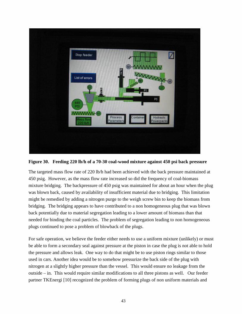
Figure 30. Feeding 220 lb/h of a 70-30 coal-wood mixture against 450 psi back pressure
The targeted mass flow rate of 220 lb/h had been achieved with the back pressure maintained at
450 psig. However, as the mass flow rate increased so did the frequency of coal-biomass
mixture bridging. The backpressure of 450 psig was maintained for about an hour when the plug
was blown back, caused by availability of insufficient material due to bridging. This limitation
might be remedied by adding a nitrogen purge to the weigh screw bin to keep the biomass from
bridging. The bridging appears to have contributed to a non homogeneous plug that was blown
back potentially due to material segregation leading to a lower amount of biomass than that
needed for binding the coal particles. The problem of segregation leading to non homogeneous
plugs continued to pose a problem of blowback of the plugs.
For safe operation, we believe the feeder either needs to use a uniform mixture (unlikely) or must
be able to form a secondary seal against pressure at the piston in case the plug is not able to hold
the pressure and allows leak. One way to do that might be to use piston rings similar to those
used in cars. Another idea would be to somehow pressurize the back side of the plug with
nitrogen at a slightly higher pressure than the vessel. This would ensure no leakage from the
outside – in. This would require similar modifications to all three pistons as well. Our feeder
partner TKEnergi [10] recognized the problem of forming plugs of non uniform materials and
44
claims to have now developed a new feeder as described in the reference that (i) seals at the
piston, (ii) does not require plugs to be formed, and (iii) thus does not require a plug breaker.
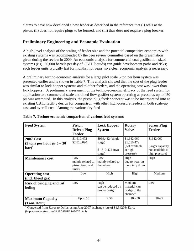
Preliminary Engineering and Economic Evaluation A high-level analysis of the scaling of feeder size and the potential competitive economics with existing systems was recommended by the peer review committee based on the presentation given during the review in 2009. An economic analysis for commercial coal gasification sized systems (e.g., 50,000 barrels per day of CBTL liquids) can guide development paths and risks; such feeder units typically last for months, not years, so a clear economic analysis is necessary. A preliminary techno-economic analysis for a large pilot scale 5 ton per hour system was presented earlier and is shown in Table 7. This analysis showed that the cost of the plug feeder was similar to lock hopper systems and to other feeders, and the operating cost was lower than lock hoppers. A preliminary assessment of the techno-economic efficacy of the feed system for application to a commercial scale entrained flow gasifier system operating at pressures up to 450 psi was attempted. In this analysis, the piston plug feeder concept was to be incorporated into an existing CBTL facility design for comparison with other high-pressure feeders in both scale-up ease and overall cost. Among the various dry feed Table 7. Techno-economic comparison of various feed systems
Feed System Piston Driven Plug Feeder
Lock Hopper System
Rotary Valve
Screw Plug Feeder
2007 Cost (5 tons per hour @ 5 – 30 bar)1
$1,610,472-$2,013,090
$939,442 (single stage) $1,610,472 (two stage)
$1,342,060 - $1,610,472 (not available at high pressure)
$1342,060 (larger capacity, not available at high pressure)
Maintenance cost Low – mainly related to piston front and liners.
Low— mainly related to the valves
High – due to wear on the rotary drum
High
Operating cost (incl. bleed gas)
Low High High Medium
Risk of bridging and rat holing
Low High – can be reduced by proper design
Medium – material can bridge in the chamber
Low
Maximum Capacity (Tons/Hour)
Up to 10 > 50 10 - 50 10-25
1. Converted from Euros to Dollar using June 2007 exchange rate of $1.34206/ Euro. (http://www.x-rates.com/d/USD/EUR/hist2007.html)

45
systems for high pressure gasifiers, none have been demonstrated commercially for coal-biomass
mixtures, and for feeding of coal alone, the only dry system that has been used in large scale
gasifiers is based on lock hoppers. However, lock hoppers suffer from a number of operating
disadvantages, including their height that would be as much as three times that for plug feeders,
and use of large amounts of inert gas for pressurization and transfer. Also since the valves
between hoppers are subject to use in the presence of large amounts of solids, they are subject to
sticking and seal failure. The plug feeder has advantages in the above aspects, but appears to
suffer from larger power consumption due to the requirement of moving plugs through pistons in
a manner similar to extrusion. Also, the plug feeder required the coal-biomass mixture to be
very consistent and homogenous in order to form plugs of sufficient integrity to form a pressure
seal.
A detailed economic analysis of the plug feeder could not be carried out due to lack of
supporting data for scale up from the manufacturer. Also the fact that the feeder would need
modifications makes the economic evaluation for the current feeder of little value. TKEnergi
[9,10] has terminated the scale up of the plug feeder and has been developing a new feeder
based on pistons and a sealing ring described in patent application WO2011/04491 A2 that can
move powders into high pressure environments and does not depend on formation of a plug to
provide a seal. This patent application is attached in Appendix C. Clearly if the mixture can be
fed without the need for forming plugs, the feeder would have significant advantages. Not only
would the power consumption be low because there would not be a need for forming and
pushing plugs through pistons, there would not be a need for the material being fed to be
uniform. Because of significant capital and operating cost advantages, this feeder would be far
superior versus lock-hoppers. However, the performance of the modified feeder is yet to be
verified.

46
Conclusions and Summary The most important results obtained in the project included:
• Coal-biomass mixtures consisting of 50 to 70 % bituminous coal and lignite mixed with woody biomass, corn stover, and switch grass were successfully prepared using a hammer mill. The size distribution and moisture content of these mixtures was measured.
• Feeder was demonstrated for feeding coal-biomass mixtures containing 50-70 % coal into a high pressure tank at 350-450 psig at variable speeds from 1 to 220 lb/h.
Based on the successful high pressure testing results, the potential advantages of the piston-plug
feeder technology are summarized below:
• The piston-plug feeder technology does not require the use of expensive lock-hopper
systems
• Bridging is not a major issue as in lock-hoppers because the feed hoppers are at low
pressure
• Biomass/coal plugs of sufficient strength and density can be formed using a hydraulic
pressure of 1600-2000 psi on the third piston.
• Biomass aids in the binding--no external binders are used.
Some limitations of the feeder technology that were brought to light during the high pressure
tests included:
• The in-homogeneity of coal-biomass mixtures caused by particle size differences
between coal and biomass and the much lower compressibility and higher density of coal
as opposed to biomass can contribute to segregation in the feed hopper that leads to non-
uniform plug formation. When this happened, the plugs were not able to hold the high
pressure.
• A seal only at the plug needs to be proven safe for use in a combustible environment
such as an entrained flow gasifier—based on a process hazard assessment carried out at
Southern, it was concluded that the feeder would need modification to provide a
secondary seal at the piston.
• Due to potential high power consumption and the sealing problem mentioned above,
TKEnergi has discontinued the scale up of the feeder, thus rendering a detailed economic
evaluation to be of little value.
47
TKEnergi is currently developing a feeder that seals at the pistons, does not require that the
mixture be uniform, does not require forming and pushing plugs, and thus requires less energy to
operate. Southern and TKEnergi are presently discussing the potential development and testing
of this new feeder in a future project.
To summarize the project at Southern,
• Biomass pretreatment system consisting of a fluidized-bed dryer and shredder and
capable of processing up to 500 lb/h biomass, was commissioned at Southern
• Coal-biomass mixtures consisting of 50 to 70 % bituminous coal and lignite mixed with
woody biomass, corn stover, and switch grass were successfully prepared using a
hammer mill.
• TKEnergi Feeder was demonstrated for feeding a coal biomass mixtures containing
greater than 50% coal into a high pressure tank at 350-450 psig at variable speeds from
25 to 220 lb/h.
• The piston-plug feeder needs to be modified to provide a secondary seal at the piston in
addition to the seal formed by the plug.
• TKEnergi is developing a new feeder that
• does not require the formation of plugs
• uses significantly less energy than the present piston-plug feeder design
• Southern and TKEnergi are presently discussing the potential development and
testing of this new feeder.
48
References [1] Liquid Transportation Fuels from Coal and Biomass: Technological Status, Costs, and
Environmental Impacts. America's Energy Future Panel on Alternative Liquid Transportation
Fuels; National Academy of Sciences; National Academy of Engineering; National Research
Council; ISBN: 0-309-13713-6 (2009)
[2] http://www.eia.gov/forecasts/aeo/pdf/0383er(2011).pdf
[3] Increasing Security and Reducing Carbon Emission of the U.S. Transportation Sector: A
Transformational Role for Coal with Biomass, NETL, DOE/NETL-2007/1298, August 2007.
[4] Affordable, Low-Carbon Diesel Fuel from Domestic Coal and Biomass”; NETL,
DOE/NETL-2009/1349; January 14, 2009.
[5] Boerrigter, H. and A. van der Drift; “Biosyngas” The Netherlands; ECN-C-112; December
2004.
[6] Entrained Flow Gasification of Biomass—Ash behavior, feeding issues, and systems
analysis, ECN-C-04-039, April 2004
[7] http://www.fischer-tropsch.org/DOE/DOE_reports/40904/40904-fr/8%20-%2096%20-
%20100,%2040904-fr,%202.96.pdf
[8] http://www.fischer-tropsch.org/DOE/DOE_reports/40904/40904-fr/5%20-%2077%20-
%20%2086,%20%2040904-fr,%204.29.pdf
[9] TKEnergi Private Communication, March 2011
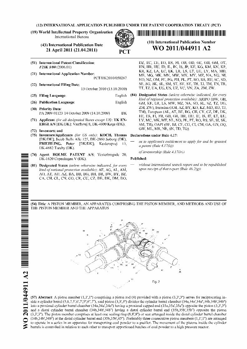
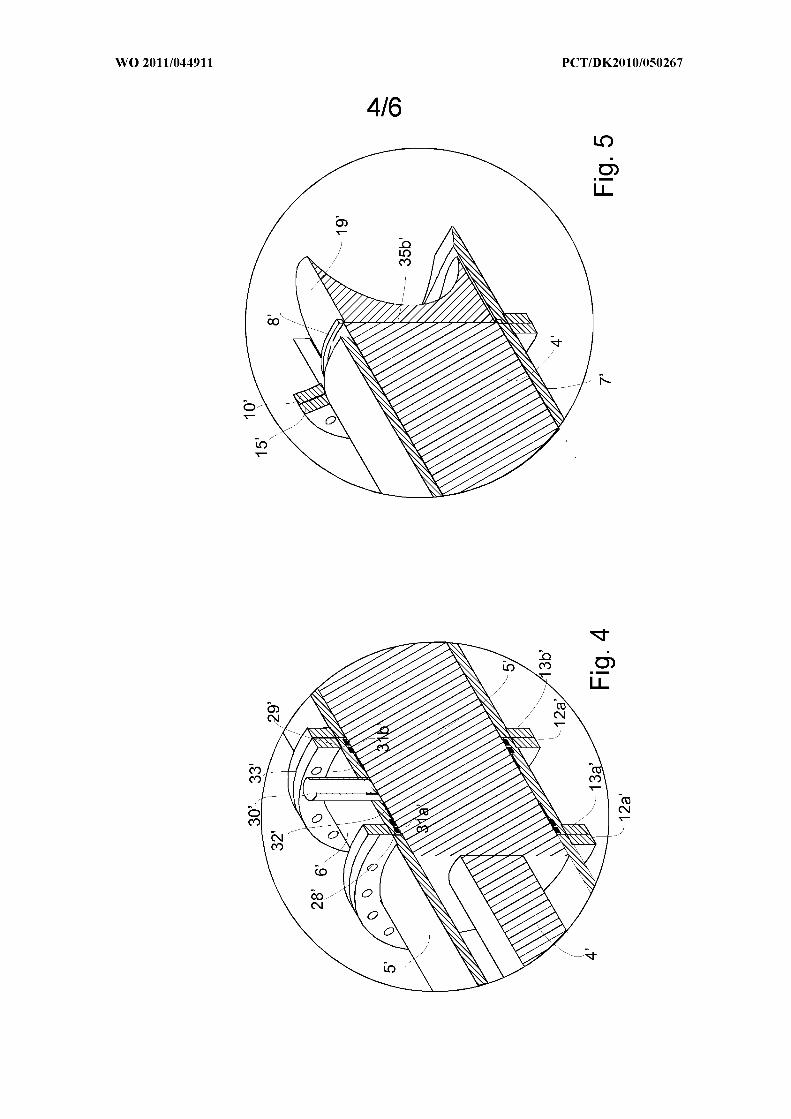
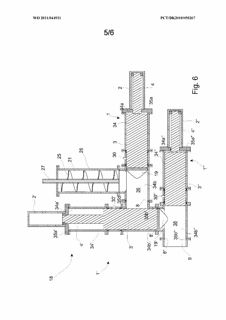
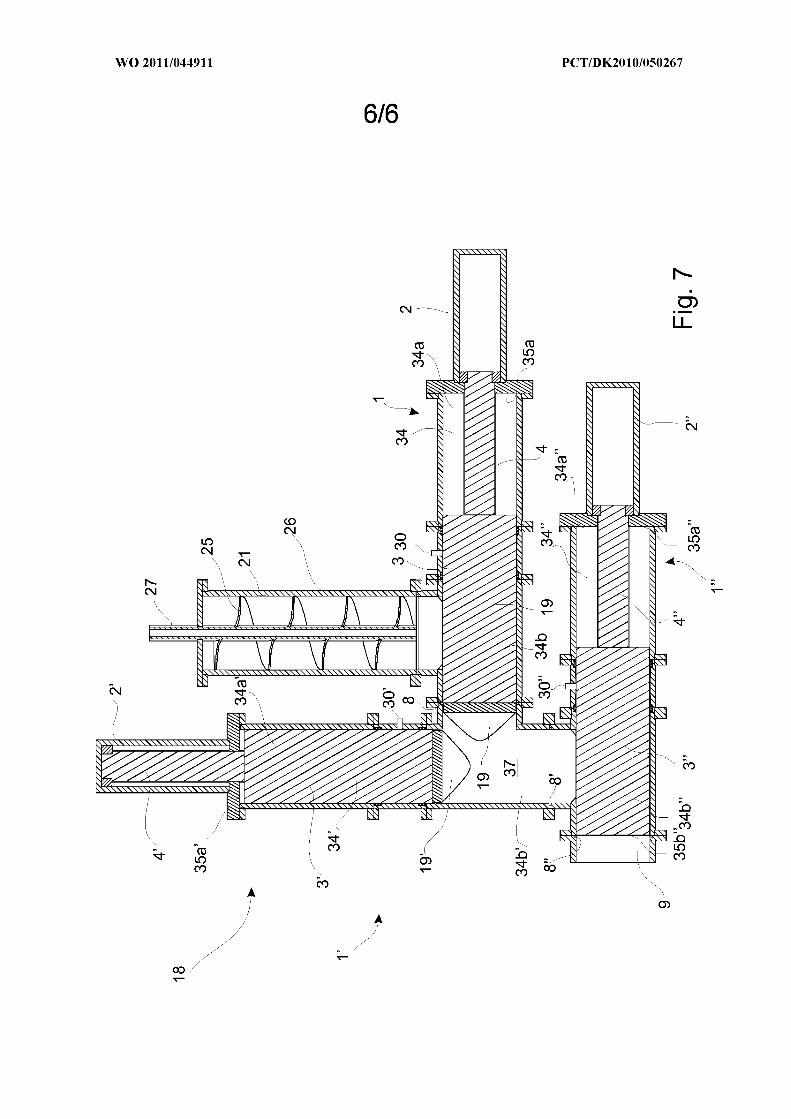
[10] T. Koch, J. Bulls Alle, and P. Friehling, A Piston Member, An Apparatus Comprising the
Piston Member, and Methods and Use of the Piston member and the Apparatus, International
Publication No. WO2011/044911 A2, April 2011
49
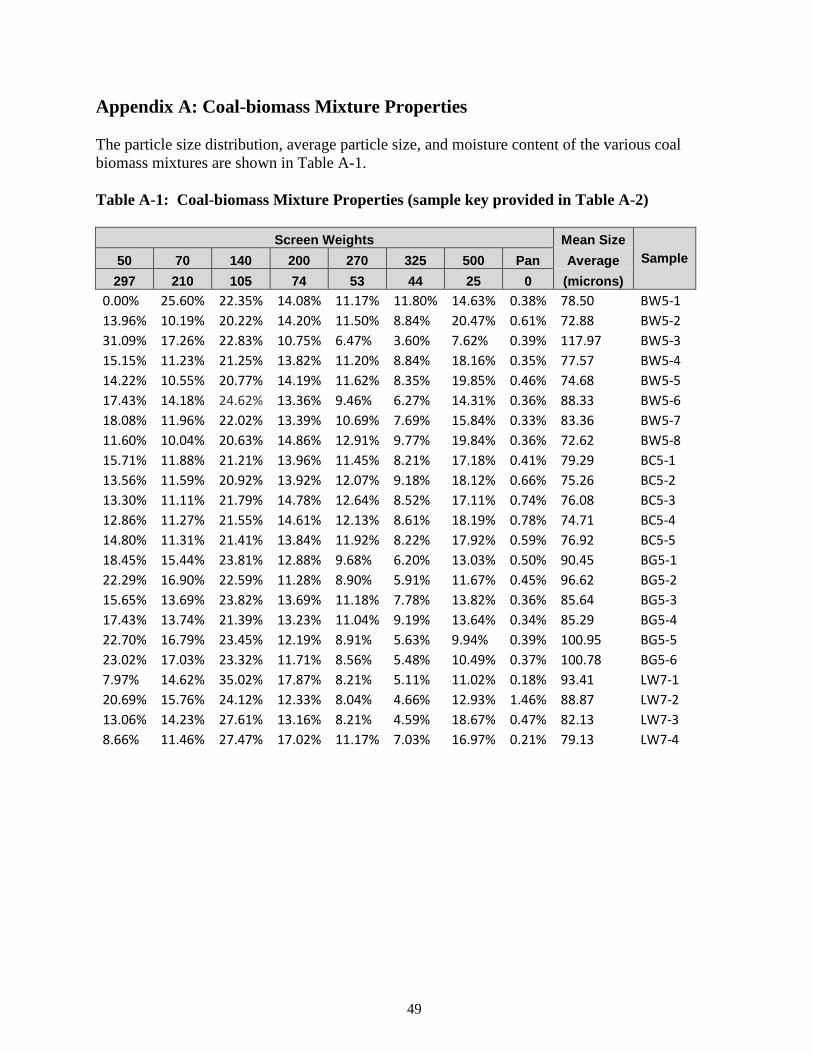
Appendix A: Coal-biomass Mixture Properties The particle size distribution, average particle size, and moisture content of the various coal biomass mixtures are shown in Table A-1. Table A-1: Coal-biomass Mixture Properties (sample key provided in Table A-2)
Screen Weights Mean Size Sample 50 70 140 200 270 325 500 Pan Average
297 210 105 74 53 44 25 0 (microns) 0.00% 25.60% 22.35% 14.08% 11.17% 11.80% 14.63% 0.38% 78.50 BW5-1
13.96% 10.19% 20.22% 14.20% 11.50% 8.84% 20.47% 0.61% 72.88 BW5-2
31.09% 17.26% 22.83% 10.75% 6.47% 3.60% 7.62% 0.39% 117.97 BW5-3
15.15% 11.23% 21.25% 13.82% 11.20% 8.84% 18.16% 0.35% 77.57 BW5-4
14.22% 10.55% 20.77% 14.19% 11.62% 8.35% 19.85% 0.46% 74.68 BW5-5
17.43% 14.18% 24.62% 13.36% 9.46% 6.27% 14.31% 0.36% 88.33 BW5-6
18.08% 11.96% 22.02% 13.39% 10.69% 7.69% 15.84% 0.33% 83.36 BW5-7
11.60% 10.04% 20.63% 14.86% 12.91% 9.77% 19.84% 0.36% 72.62 BW5-8
15.71% 11.88% 21.21% 13.96% 11.45% 8.21% 17.18% 0.41% 79.29 BC5-1
13.56% 11.59% 20.92% 13.92% 12.07% 9.18% 18.12% 0.66% 75.26 BC5-2
13.30% 11.11% 21.79% 14.78% 12.64% 8.52% 17.11% 0.74% 76.08 BC5-3
12.86% 11.27% 21.55% 14.61% 12.13% 8.61% 18.19% 0.78% 74.71 BC5-4
14.80% 11.31% 21.41% 13.84% 11.92% 8.22% 17.92% 0.59% 76.92 BC5-5
18.45% 15.44% 23.81% 12.88% 9.68% 6.20% 13.03% 0.50% 90.45 BG5-1
22.29% 16.90% 22.59% 11.28% 8.90% 5.91% 11.67% 0.45% 96.62 BG5-2
15.65% 13.69% 23.82% 13.69% 11.18% 7.78% 13.82% 0.36% 85.64 BG5-3
17.43% 13.74% 21.39% 13.23% 11.04% 9.19% 13.64% 0.34% 85.29 BG5-4
22.70% 16.79% 23.45% 12.19% 8.91% 5.63% 9.94% 0.39% 100.95 BG5-5
23.02% 17.03% 23.32% 11.71% 8.56% 5.48% 10.49% 0.37% 100.78 BG5-6
7.97% 14.62% 35.02% 17.87% 8.21% 5.11% 11.02% 0.18% 93.41 LW7-1
20.69% 15.76% 24.12% 12.33% 8.04% 4.66% 12.93% 1.46% 88.87 LW7-2
13.06% 14.23% 27.61% 13.16% 8.21% 4.59% 18.67% 0.47% 82.13 LW7-3
8.66% 11.46% 27.47% 17.02% 11.17% 7.03% 16.97% 0.21% 79.13 LW7-4
50
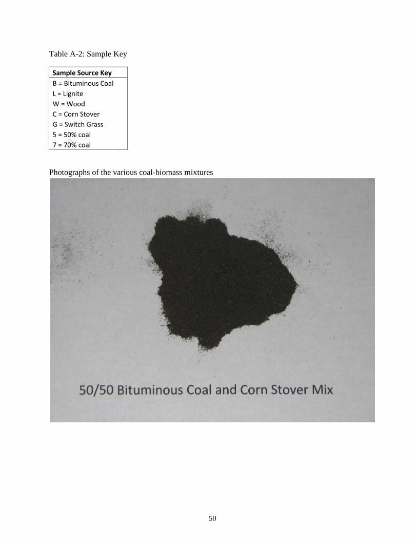
Table A-2: Sample Key
Sample Source Key
B = Bituminous Coal
L = Lignite
W = Wood
C = Corn Stover
G = Switch Grass
5 = 50% coal
7 = 70% coal
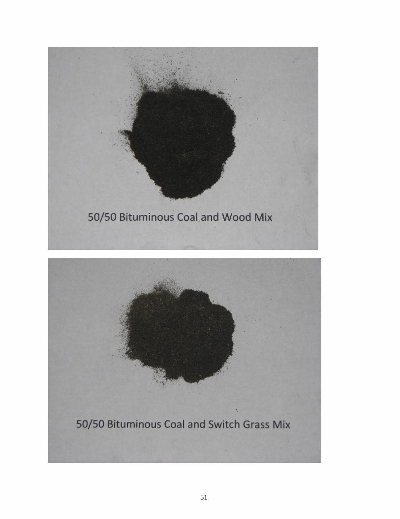
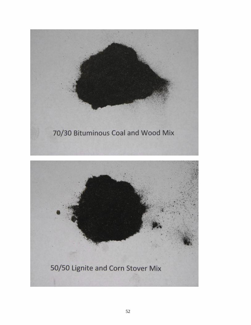
Photographs of the various coal-biomass mixtures
51
52
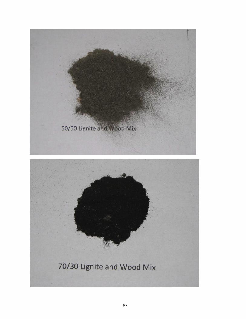
53
54
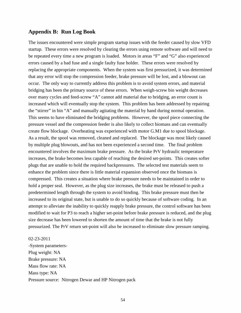
Appendix B: Run Log Book
The issues encountered were simple program startup issues with the feeder caused by slow VFD
startup. These errors were resolved by clearing the errors using remote software and will need to
be repeated every time a new program is loaded. Motors in areas “F” and “G” also experienced
errors caused by a bad fuse and a single faulty fuse holder. These errors were resolved by
replacing the appropriate components. When the system was first pressurized, it was determined
that any error will stop the compression feeder, brake pressure will be lost, and a blowout can
occur. The only way to currently address this problem is to avoid system errors, and material
bridging has been the primary source of these errors. When weigh-screw bin weight decreases
over many cycles and feed-screw “A” cannot add material due to bridging, an error count is
increased which will eventually stop the system. This problem has been addressed by repairing
the “stirrer” in bin “A” and manually agitating the material by hand during normal operation.
This seems to have eliminated the bridging problems. However, the spool piece connecting the
pressure vessel and the compression feeder is also likely to collect biomass and can eventually
create flow blockage. Overheating was experienced with motor G.M1 due to spool blockage.
As a result, the spool was removed, cleaned and replaced. The blockage was most likely caused
by multiple plug blowouts, and has not been experienced a second time. The final problem
encountered involves the maximum brake pressure. As the brake PrV hydraulic temperature
increases, the brake becomes less capable of reaching the desired set-points. This creates softer
plugs that are unable to hold the required backpressures. The selected test materials seem to
enhance the problem since there is little material expansion observed once the biomass is
compressed. This creates a situation where brake pressure needs to be maintained in order to
hold a proper seal. However, as the plug size increases, the brake must be released to push a
predetermined length through the system to avoid binding. This brake pressure must then be
increased to its original state, but is unable to do so quickly because of software coding. In an
attempt to alleviate the inability to quickly reapply brake pressure, the control software has been
modified to wait for P3 to reach a higher set-point before brake pressure is reduced, and the plug
size decrease has been lowered to shorten the amount of time that the brake is not fully
pressurized. The PrV return set-point will also be increased to eliminate slow pressure ramping.
02-23-2011
-System parameters-
Plug weight: NA
Brake pressure: NA
Mass flow rate: NA
Mass type: NA
Pressure source: Nitrogen Dewar and HP Nitrogen pack
55
This trial was run to determine base leak rate for vessel V-8. The 3-stage plug feeder was
disconnected from the vessel, and a blind flange was used in place of the feeder. A nitrogen
dewar was used to saturate the system with nitrogen at a targeted pressure increase of 300 PSI/hr.
The inline pressure regulator immediately experienced freezing and caused unregulated nitrogen
flow. The nitrogen source was isolated from the vessel and the system was depressurized.
02-24-2011
-System parameters-
Plug weight: NA
Brake pressure: NA
Mass flow rate: NA
Mass type: NA
Pressure source: Nitrogen dewar and HP Nitrogen pack
This trial was a continued attempt to determine base leak rate for vessel V-8. The targeted
pressurization rate was decreased to 200 PSI/hr. The regulator continued to experience freezing,
so the source was isolated and the system depressurized. A regulator bypass valve was installed
to eliminate freezing. The nitrogen flow was controlled using a simple needle valve. Vessel
pressure was increased to ~190 PSI using the dewar. The nitrogen dewar and vessel was then
isolated, and line pressure was bled upstream of the vessel. The nitrogen dewar was then
replaced with a 3000 PSI nitrogen 16-pack. Vessel pressure reached 277 PSI and was then
isolated in order to continue the process tomorrow. All pressure control data tags were updated
and imported into the data historian.
02-25-2011
-System parameters-
Plug weight: NA
Brake pressure: NA
Mass flow rate: NA
Mass type: NA
Pressure source: Nitrogen dewar and HP Nitrogen pack
This trial was a continued attempt to determine base leak rate for vessel V-8. Vessel pressure
was increased from ~277 PSI to 500 PSI in about 1 hour. The vessel was isolated at 09:11 and
remained in isolation until 11:11. Over a 2 hr period there was an observed pressure decrease of
8 PSI (498.7 – 490.7). The Vessel pressure was then decreased to 450 PSI. The vessel was
isolated at 13:43 and remained isolated until 15:43. Over this 2 hour period there was a pressure
increase of 1.1 PSI (449.7 – 450.8), most likely caused by ambient temperature increase. This
run confirmed that there was no leak in the system.
56
02-28
-System parameters-
Plug weight: 0.5 lb
Brake pressure: 1500 PSI
Mass flow rate: 220 lb/hr
Mass type: 50/50 by weight, bituminous coal and wood mix
Pressure source: Nitrogen dewar and HP Nitrogen pack
This trial was run to ensure the correct functionality of the compression feeder system. The
blind flange was removed, and the vessel and feeder were joined using a spool coupling. Upon
startup, the error “B.M1 faulted” immediately caused to system to fail. The problem was
determined to be a simple startup error. Every time the operational program is changed and/or
reloaded, this error must be lifted using remote software.
03-01-2011
-System parameters-
Plug weight: 0.5 lb
Brake pressure: 1500 PSI
Mass flow rate: 220 lb/hr
Mass type: 50/50 by weight, bituminous coal and wood mix
Pressure source: Nitrogen dewar and HP Nitrogen pack
This trial was a continuation to ensure the correct functionality of the compression feeder
system. Startup immediately caused the errors “G.M1 motor protector tripped” and “F.M1 motor
protector tripped”. The hydraulic power packs also failed to initiate. The control board was
traced and all voltages were checked. The fuse holder –F10/2 was found to have a blown fuse.
The fuse was replaced (3A / 600V) and was immediately blown on compression feeder startup.
A new external fuse holder was purchased, and the fuse rating was increased to 5A.
The compression feeder was tested under “manual mode” and each motor functioned correctly.
However, when the feeder was run in “automatic mode”, motors G.M1 and F.M1 still failed to
initiate. These motors should always be activated and running under normal operation. The
control program was modified to ensure that these two motors are always activated and running
when the compression feeder is active. The compression feeder currently functions properly.
03-02-2011
-System parameters-
Plug weight: 0.5 lb
Brake pressure: 1500 PSI
57
Mass flow rate: 220 lb/hr
Mass type: 50/50 by weight, bituminous coal and wood mix
Pressure source: Nitrogen dewar and HP Nitrogen pack
This trial was run to ensure the proper functionality of the pressure control system. A low
pressure of ~40 PSI was applied to the system. The backflow regulator PCV-8026 failed to
regulate the pressure. After careful inspection, the system component PCV-8026 was
determined to be a pilot pressure controlled regulator. This part could not achieve the required
functionality without significant pressure control system modifications and additions. As a
result, a new regulator (spring controlled) would need to be purchased.
03-03-2011
-System parameters-
Plug weight: NA
Brake pressure: NA
Mass flow rate: NA
Mass type: NA
Pressure source: NA
The project was put on hold until the new regulator was shipped and received. Tescom back-
pressure regulator 26-176524 was purchased from W. K. Hile Company Inc.
03-07-2011
-System parameters-
Plug weight: 0.5 lb
Brake pressure: 1500 PSI
Mass flow rate: 221 lb/hr – 1lb/hr
Mass type: 50/50 by weight, bituminous coal and wood mix
Pressure source: Nitrogen dewar and HP Nitrogen pack
Trial time: 08:30 – 16:30
This trial was run to determine the leak rate across a biomass plug formed under full system
pressure. The new backflow regulator was installed and a plug was formed at atmospheric
pressure and a feed rate of 220 lb/hr. The system was then pressurized using an N2 dewar to ~55
PSI and the backflow regulator was determined to be fully functional. Mass flow rate was
decreased to 1 lb/hr and the pressure was increased until 140 PSI was reached. The vessel was
isolated and the N2 dewar was replaced with a HP N2 16-pack. Pressure was applied to the
vessel with a source/vessel pressure difference of ~100 PSI. The system was put into normal
shutdown, at a vessel pressure of 348 PSI, as an attempt to maintain vessel pressure overnight.
The vessel began to lose pressure rapidly and the system was restarted. Error “E.PT: Do not
58
pressurize before plug is OK” was lifted. 348 PSI Plug blowout occurred at 16:14. ESTOP
manually triggered at 16:15. The Conex (compression feeder) was thoroughly cleaned, paying
special attention to the load cells and piston assemblies.
03-08-2011
-System parameters-
Plug weight: 0.5 lb
Brake pressure: 1500 PSI
Mass flow rate: 221 lb/hr – 1lb/hr
Mass type: 50/50 by weight, bituminous coal and wood mix
Pressure source: Nitrogen dewar and HP Nitrogen pack
Trial time: 08:33 – 16:30
This trial was run to determine the leak rate across a biomass plug formed under full system
pressure. A biomass plug was formed at atmospheric pressure and a mass flow rate of 220 lb/hr.
The mass flow rate was then decreased to 1 lb/hr and the system was pressurized to ~140 PSI
using an N2 dewar. The vessel was isolated and the N2 dewar was replaced with a HP N2 16-
pack. Mass flow rate was increased to 2 lb/hr. Pressure was applied to the vessel with a
source/vessel pressure difference of ~100 PSI. Vessel pressure reached 372 PSI. Error “B: Out
of Material” occurred at 13:33. Plug blowout began at 13:33. The ESTOP was manually
triggered at 13:35. The system was started under normal operation at atmospheric pressure to
remove any fully formed plugs from the compression system. Conex was then cleaned.
03-09-2011
-System parameters-
Plug weight: 0.5 lb
Brake pressure: 1900 PSI
Mass flow rate: 220 lb/hr – 120 lb/hr
Mass type: 50/50 by weight, bituminous coal and wood mix
Pressure source: Nitrogen dewar and HP Nitrogen pack
Trial time: 08:40 – 09:50
This trial was run to determine the leak rate across a biomass plug formed under full system
pressure. TK Energy had been contacted regarding previous blowouts. They recommended
increasing the brake pressure. SRI resources also recommended increasing the mass flow rate.
A biomass plug was formed at atmospheric pressure and a feed rate of 220 lb/hr. The mass feed
rate was then decreased to 120 lb/hr. The system was pressurized using an N2 dewar. Pressure
was applied to the vessel with a source/vessel pressure difference of ~100 PSI. Error “B: Out of
Material” and “A: Out of Material” occurred at 09:39. Vessel pressure reached 34 PSI. Plug
59
blowout occurred at 09:43. The ESTOP was triggered manually. The Conex (compression
feeder) was thoroughly cleaned, paying special attention to the load cells and piston assemblies.
-System parameters-
Plug weight: 0.5 lb
Brake pressure: 1900 PSI
Mass flow rate: 220 lb/hr – 120 lb/hr
Mass type: 50/50 by weight, bituminous coal and wood mix
Pressure source: Nitrogen dewar and HP Nitrogen pack
Trial time: 14:02 – 14:31
The previous trial was repeated and received the same errors. Max vessel pressure observed was
20 PSI.
03-14-2011
-System parameters-
Plug weight: 1 lb
Brake pressure: 1900 PSI
Mass flow rate: 220 lb/hr – 120 lb/hr
Mass type: 50/50 by weight, bituminous coal and wood mix
Pressure source: Atmospheric
The trial procedures have remained the same with the exception of a few program changes and a
plug weight increase of .5 lb. Currently, the largest concern is the decrease of the brake pressure
during normal operation. This seems to be the cause of every recorded plug blowout. Possible
causes include P3 pressure limits, “secure mode” parameters, and “stop mode” parameters”. The
maximum limit of P3 was increased to 2700 PSI in order to stop the brake pressure from
dropping to 100 PSI during normal operation. “Secure mode” brake pressure set-point was
increased from 100 PSI to 200 PSI to help identify the software routine being called when the
pressure decrease occurs.
Atmospheric trial start: 08:53
Bin weight: 240 lb
Brake pressure: 1900 PSI
Mass flow rate: 220 lb/hr
Plug weight: 1.0 lb
-08:55 error "B.out_of_material"
-08:55 system "shutdown"
60
Atmospheric trial start: 08:59
Bin weight: 140 lb
Brake pressure: 1900 PSI
Mass flow rate: 220 lb/hr
Plug weight: 1.0 lb
-09:20 - abnormal drop in brake pressure SP 1750 PSI --> 1600 PSI
-09:23 - abnormal drop in brake pressure SP 1850 PSI --> 100 PSI
-09:29 - "normal shutdown"
Atmospheric trial start: 10:46
Bin weight: 40 lb
Brake pressure: 1900 PSI
Mass flow rate: 220 lb/hr
Plug weight: 1.0 lb
-11:09: abnormal drop in brake pressure SP 1750 PSI --> 100 PSI
-11:10: "normal shutdown"
P3 software pressure limit changed from 2000PSI --> 2700PSI
Atmospheric trial start: 14:03
Bin weight: ~0 lb
Brake pressure: 1900 PSI
Mass flow rate: 220 lb/hr
Plug weight: 1.0 lb
-14:26: abnormal drop in brake pressure SP 1750 PSI --> 100 PSI
-14:27: "normal shutdown"
Loaded feeder bin with 2x 120lbs (BW5-5 and BW5-6)
Atmospheric trial start: 15:11
Bin weight: 240 lb
Brake pressure: 1900 PSI
Mass flow rate: 220 lb/hr
Plug weight: 1.0 lb
-15:38: abnormal drop in brake pressure SP 1899 PSI --> 100 PSI
-15:39: "normal shutdown"
Atmospheric trial start: 16:00
Bin weight: 140 lb
61
Brake pressure: 1900 PSI
Mass flow rate: 220 lb/hr
Plug weight: 1.0 lb
-16:28: abnormal drop in brake pressure SP 1899 PSI --> 100 PSI
-16:29: "normal shutdown"
Every trial run this day saw a quick decrease in brake pressure set-point. The pressure of P3
had been determined to be unrelated to the brake pressure drop.
03-15-2011
-System parameters-
Plug weight: 1 lb
Brake pressure: 1900 PSI
Mass flow rate: 220 lb/hr – 120 lb/hr
Mass type: 50/50 by weight, bituminous coal and wood mix
Pressure source: Nitrogen dewar and HP Nitrogen pack
The program has been defaulting to “secure mode” based on previous trial observations. This
appears to be within normal operating parameters. The underlying cause then appears to be
material bridging. The loading bin and weigh bin will be closely monitored during all following
trials.
Atmospheric trial start: 11:51
Bin weight: 400+ lb
Brake pressure: 1900 PSI
Mass flow rate: 20 lb/hr
Plug weight: 1.0 lb
-16:32 error "B.out_of_material"
- Area "A" bin was visually inspected and contained an estimated 300 lbs of biomass
- The weigh screw bin was determined to have contained no biomass, possibly due to bridging
- The data trend suggests that there was little to no fluctuation of the weigh screw weight, cause
remains unknown, but material bridging is likely.
-17:22 plug blow-out
03-16
-System parameters-
Plug weight: 1 lb
62
Brake pressure: 1900 PSI
Mass flow rate: 220 lb/hr – 120 lb/hr
Mass type: 50/50 by weight, bituminous coal and wood mix
Pressure source: Nitrogen dewar and HP Nitrogen pack
The cause of brake pressure loss is due to bridging in area B. The weigh screw weight
continually decreases and there is no observable weight increase as motor A.M1 in running.
This suggests that there is material bridging. Upon further investigation, some of the material
bridging was caused by broken bolts holding the agitator blades to the rotating shaft. This
assembly was repaired and the system was run in “normal operation” again. Shortly after startup,
the error “G.M1 Motor Protector Tripped” was displayed and the system went into “stop mode”
causing the system pressure to rapidly decrease along with the decreased brake pressure. The
cause was due to blockage in the spool connecting the vessel and compression system. The
spool was taken off of the vessel and the blockage was removed.
03-17-2011
-System parameters-
Plug weight: 1 lb
Brake pressure: 1900 PSI
Mass flow rate: 220 lb/hr – 120 lb/hr
Mass type: 50/50 by weight, bituminous coal and wood mix
Pressure source: Nitrogen dewar and HP Nitrogen pack
The brake pressure never reached its maximum set-point. This was most likely caused by the
increased temperatures observed on the brake’s PrV. To counter the increasing PrV temperature,
nitrogen gas was applied directly to the valve. The brake still reached its maximum pressure
limit near 1750 PSI, and the nitrogen seemed to have little effect. This limited the amount of
backpressure that could be applied to the biomass being fed. When the PrV set-point was
reduced to allow a decrease in plug length, the program slowly increased the brake pressure back
to the desired set-point. This pressure increase needs to occur much quicker. In addition, the
biomass continuously bridged. As a result, the bin in area “A” needed to be frequently agitated
by hand (about every 10 min @ flow of 25 lb/hr). The weigh screw weight also needed to be
closely monitored to ensure that mass was entering the compression system and to ensure that
bridging did not also occur within the weigh bin.
Summary of events:
Default program errors and reset
63
Control circuits and fuses
Compression feeder startup under pressure
Material bridging and “out of material” errors
Brake pressure
Plug weight
Material properties: compression, relaxation, and frictional (adhesion to steel)
PrV temperatures and pressure limits
03-17-2011
-Trial start: 10:41
-System parameters-
Plug weight: 1 lb
Brake pressure: 1900 PSI
Mass flow rate: 25 lb/hr – 220 lb/hr
Mass type: 50/50 by weight and 70/30 by weight, bituminous coal and wood mix
Pressure source: Nitrogen dewar and HP Nitrogen pack
The control program was edited to maintain a constant brake pressure when system backpressure
reached a predetermined value. The purpose of this change was to ensure minimal brake
pressure variance when plug length increased beyond the maximum limit. This should allow the
PrV to reach its previous set-point much faster and allow for quick system recovery.
The trial began with about 160 lbs of a 50/50 bituminous coal and wood blend. The mass flow
rate was kept at 25 lb/hr during plug formation and primary pressurization using an N2 dewar.
When the system backpressure reached 100 PSI, the program additions worked as they should
and the brake pressure set-point was fixed at 1850 PSI. At 13:58 the biomass type was switched
to 70/30 bituminous coal and wood blend. The N2 source was also switched to a high pressure
nitrogen 16-pack with current system pressure at 115 PSI. At these low pressures and low mass
flow rate, very little material bridging was observed compared to material bridging at higher
flow rates from previous trials. Backpressure continued to build to 429 PSI and then the mass
flow rate began to gradually increase from 25 lb/hr to its maximum flow of 220 lb/hr. As the
mass flow rate increased so did the frequency of biomass bridging. A backpressure of 450 PSI
was reached at 16:00 and was maintained until 16:45. Plug blow-out occurred at 16:46. The
cause of this blow-out was most likely due to a decrease in required mass flow caused by
bridging at high mass flow rates. This limitation can be remedied by adding a nitrogen purge to
the weigh screw bin to keep the biomass from bridging.
64
03-31-2011
Atmospheric trial start:
Bin weight: ~120 lb
Brake pressure: 1750 PSI
Mass flow rate: 220 lb/hr
Plug weight: 1.0 lb
A compressed air purge system was installed on the weigh bin in order to help eliminate material
bridging. The compression system was run at atmospheric pressure using a 70/30 blend bit-coal
and wood. The error counts remained, but were immediately lifted when the purge system
moved the material from the loading bin. The data trends look very consistent, and material is
being constantly fed. Although there is still bridging, the problem has been alleviated to the
point that a successful trial can be run without stoppage due to lack of material flow and material
bridging.
04-01-2011
-Trial start: 10:41
-System parameters-
Plug weight: 1 lb
Brake pressure: 1850 PSI
Mass flow rate: 25 lb/hr
Mass type: 70/30 by weight, bituminous coal and wood mix
Pressure source: Nitrogen dewar and HP Nitrogen pack
The purpose of this trial was to test the functionality of the compressed air purge under high
system pressure. The system software continuously alerted of weigh bin errors after every load
bin motor cycle. This was due to the delay caused by the new purge system. As the load bin fed
biomass, the end of the feed tube would collect mass. The purge would then break the mass
loose and it would fall into the weigh bin at a slow but consistent rate. Data trends showed that
the biomass feeder was receiving a steady stream of biomass, and little to no bridging was
occurring. Plug failure and system blowout occurred at a vessel pressure of ~360 PSI. There
were no immediately noticeable actions or trends that could have caused the blowout.

65
Appedix C: TKEnergi Patent Application for Modifie d Feeder