DEM Analysis of Backfilled Walls Subjected to Active ... · DEM Analysis of Backfilled Walls...
7
* Corresponding author. Tel.: +982182084398. E-mail address: [email protected] (M.H. Khosravi). Journal Homepage: ijmge.ut.ac.ir DEM Analysis of Backfilled Walls Subjected to Active Translation Mode Mohammad Hossein Khosravi a, * , Farzaneh Hamedi Azad b , Mojtaba Bahaaddini c, d , Thirapong Pipatpongsa e a School of Mining Engineering, College of Engineering, University of Tehran, Iran b Department of Geotechnical Engineering, Bonyan Zamin Consulting Engineers, Tehran, Iran c Department of Mining Engineering, Higher Education Complex of Zarand, Zarand, Iran d Shahid Bahonar University of Kerman, Kerman, Iran e Department of Urban Management, Kyoto University, Japan A B S T R A C T In this paper, the problem of a retaining wall under active translation mode was numerically investigated. A series of numerical models was conducted using the discrete element code, PFC2D. The backfill soil was simulated by an assembly of separate cohesionless circular particles. Backfill soil was prepared by pouring soil particles from a specific height under gravity force and giving them enough time for appropriate settlement. Different heights of retaining walls were simulated and the lateral earth pressure on the wall was observed under both at-rest and active conditions. Numerical results were compared with predictions from several analytical methods and measurements from physical models. The active state of earth pressure was defined as the earth pressure distribution corresponding to the values of wall displacement where the failure zone in the backfill was fully developed. The numerical results showed that the fully active state of earth pressure occurred at a wall displacement corresponding to the strains required for reaching the critical state in biaxial compressive tests. Keywords : Numerical analysis, Retaining walls, Lateral earth pressure, PFC2D 1. Introduction Retaining walls are constructed for various engineering problems, especially for civil and mining projects. Some very common types of projects which retaining walls are constructed are foundation pits, hydraulic structures, highways and railways. There is a soil-structure interaction between the retained soil and retaining structure which is one of the main concerns of geotechnical engineers who design such structures. The value and distribution of the lateral pressure exerted by retained soil or backfill against the retaining structure is very important and has been the subject of many researches. The earliest formulations of lateral earth pressure were conducted by Coulomb [1] and Rankine [2]. On one hand, Coulomb developed an upper-bound solution by considering the soil wedge between the retaining wall and the slip line under the limit equilibrium. On the other hand, Rankine developed a lower-bound solution by considering the plastic state of stress for a soil retained by a vertical and perfectly rough wall using the concept of Mohr circle. It is noticeable that those classical theories have resulted in a linear lateral earth pressure distribution on the wall. However, it was later shown that the distribution of lateral earth pressure on a retaining wall can be non-linear depending on many parameters such as the mode of wall movement, density of backfill soil and soil-wall interface friction angle [3-9]. The theory of arching in granular materials is attributed to Janssen [10] who defined it initially as the silo effect. This theory is later extended to earth ditches and buried structures [11-13], hoppers and bunkers [14-15], slopes [16-19] and retaining walls [20-24]. Terzaghi [12] addressed that the lateral earth pressure does not reach the maximum value at the toe of the wall, but at some higher levels, and he defined the concept of soil arching behind the retaining walls. He introduced the soil arching as the ability of soil particles to transfer earth pressures from yielding to stable portions. Tsagareli [25] conducted a series of large scale instrumented physical models for a rigid retaining wall under active translation mode. He concluded that the slip surface behind the wall was independent of the wall height, and therefore, the lateral earth pressure distribution on the wall was non-linear. Sherif and Fang [26] employed a shaking table to study the dynamic earth pressures on retaining walls rotating about the top. The results showed that the distribution of the dynaimc active lateral earth pressure on the wall was non-linear and reduced to zero at the base of the wall. Fang and Ishibashi [3] studied the lateral active earth pressure on a retaining wall model for different modes of wall movements including rotation about the top, rotation about the toe and translation. They concluded that the stress distribution on the wall was non-linear and its pattern to depend on the wall movement mode and the soil density. Therefore, the magnitude of the total thrust on the wall and the point of its application differ from those predicted by classical theories. Niedostatkiewicz et al. [27] experimentally investigated the evolution of shear bands in cohesionless backfill sand behind retaining walls. They performed a small scale laboratory setup for active and passive cases of a rigid retaining wall subjected to different modes of movement. They concluded that the arrangement of shear zone patterns behind the wall mainly depended on the type of wall movement and the thickness of shear zone on the initial void ratio of backfill sand. The effect of soil arching on the lateral earth pressure behind rigid retaining walls was investigated initially by Handy [20]. Later, many Article History: Received: 08 May 2017, Revised: 19 July 2017, Accepted: 07 August 2017.
Transcript of DEM Analysis of Backfilled Walls Subjected to Active ... · DEM Analysis of Backfilled Walls...

* Corresponding author. Tel.: +982182084398. E-mail address: [email protected] (M.H. Khosravi).
Journal Homepage: ijmge.ut.ac.ir
DEM Analysis of Backfilled Walls Subjected to Active Translation Mode
Mohammad Hossein Khosravi a, *, Farzaneh Hamedi Azad b, Mojtaba Bahaaddini c, d, Thirapong Pipatpongsa e
a School of Mining Engineering, College of Engineering, University of Tehran, Iran b Department of Geotechnical Engineering, Bonyan Zamin Consulting Engineers, Tehran, Iran c Department of Mining Engineering, Higher Education Complex of Zarand, Zarand, Iran d Shahid Bahonar University of Kerman, Kerman, Iran e Department of Urban Management, Kyoto University, Japan
A B S T R A C T
In this paper, the problem of a retaining wall under active translation mode was numerically investigated. A series of numerical models was conducted using the discrete element code, PFC2D. The backfill soil was simulated by an assembly of separate cohesionless circular particles. Backfill soil was prepared by pouring soil particles from a specific height under gravity force and giving them enough time for appropriate settlement. Different heights of retaining walls were simulated and the lateral earth pressure on the wall was observed under both at-rest and active conditions. Numerical results were compared with predictions from several analytical methods and measurements from physical models. The active state of earth pressure was defined as the earth pressure distribution corresponding to the values of wall displacement where the failure zone in the backfill was fully developed. The numerical results showed that the fully active state of earth pressure occurred at a wall displacement corresponding to the strains required for reaching the critical state in biaxial compressive tests.
Keywords : Numerical analysis, Retaining walls, Lateral earth pressure, PFC2D
1. Introduction
Retaining walls are constructed for various engineering problems, especially for civil and mining projects. Some very common types of projects which retaining walls are constructed are foundation pits, hydraulic structures, highways and railways. There is a soil-structure interaction between the retained soil and retaining structure which is one of the main concerns of geotechnical engineers who design such structures. The value and distribution of the lateral pressure exerted by retained soil or backfill against the retaining structure is very important and has been the subject of many researches. The earliest formulations of lateral earth pressure were conducted by Coulomb [1] and Rankine [2]. On one hand, Coulomb developed an upper-bound solution by considering the soil wedge between the retaining wall and the slip line under the limit equilibrium. On the other hand, Rankine developed a lower-bound solution by considering the plastic state of stress for a soil retained by a vertical and perfectly rough wall using the concept of Mohr circle. It is noticeable that those classical theories have resulted in a linear lateral earth pressure distribution on the wall. However, it was later shown that the distribution of lateral earth pressure on a retaining wall can be non-linear depending on many parameters such as the mode of wall movement, density of backfill soil and soil-wall interface friction angle [3-9].
The theory of arching in granular materials is attributed to Janssen [10] who defined it initially as the silo effect. This theory is later extended to earth ditches and buried structures [11-13], hoppers and bunkers [14-15], slopes [16-19] and retaining walls [20-24].
Terzaghi [12] addressed that the lateral earth pressure does not reach
the maximum value at the toe of the wall, but at some higher levels, and he defined the concept of soil arching behind the retaining walls. He introduced the soil arching as the ability of soil particles to transfer earth pressures from yielding to stable portions.
Tsagareli [25] conducted a series of large scale instrumented physical models for a rigid retaining wall under active translation mode. He concluded that the slip surface behind the wall was independent of the wall height, and therefore, the lateral earth pressure distribution on the wall was non-linear.
Sherif and Fang [26] employed a shaking table to study the dynamic earth pressures on retaining walls rotating about the top. The results showed that the distribution of the dynaimc active lateral earth pressure on the wall was non-linear and reduced to zero at the base of the wall.
Fang and Ishibashi [3] studied the lateral active earth pressure on a retaining wall model for different modes of wall movements including rotation about the top, rotation about the toe and translation. They concluded that the stress distribution on the wall was non-linear and its pattern to depend on the wall movement mode and the soil density. Therefore, the magnitude of the total thrust on the wall and the point of its application differ from those predicted by classical theories.
Niedostatkiewicz et al. [27] experimentally investigated the evolution of shear bands in cohesionless backfill sand behind retaining walls. They performed a small scale laboratory setup for active and passive cases of a rigid retaining wall subjected to different modes of movement. They concluded that the arrangement of shear zone patterns behind the wall mainly depended on the type of wall movement and the thickness of shear zone on the initial void ratio of backfill sand.
The effect of soil arching on the lateral earth pressure behind rigid retaining walls was investigated initially by Handy [20]. Later, many
Article History: Received: 08 May 2017, Revised: 19 July 2017, Accepted: 07 August 2017.

192 M.H. Khosravi et al. / Int. J. Min. & Geo-Eng. (IJMGE), 51-2 (2017) 191-197
other formulations were developed attempting to improve the formulation of Handy [21-23]. In most of those formulations, a differential flat element was assumed between the wall and the Coulomb slip line to investigate a one-dimensional system of equilibrium. Although this simplification was helpful to predict the stress distribution against the wall, the stress distribution inside the failure wedge remained unknown. Khosravi et al. [24] improved the existing formulations by applying a two-dimensional system of equilibrium to derive a formulation for estimation of vertical, horizontal and shear stresses at any arbitrary point inside the failure wedge as well as along the retaining wall.
Using experimental and analytical approaches, a large number of studies have been carried out to investigate the lateral earth pressure on retaining wall. However, the main mechanism which controls the behavior of retaining wall is unknown and further studies are required. Numerical modelling provides a low cost and scientific tool to study the effects of different parameters and controlling mechanism without the difficulties in preparation and conducting experiments. Extensive numerical modeling, mostly using Finite Element Method (FEM), have been performed to estimate the lateral earth pressure exerting from the retained soil against the wall [4,5,28-30]. Despite the suitability of FEM for problems of retaining wall, Discrete Element Method (DEM) is confirmed to be a more agreeable alternative approach for simulation of large soil displacements and particle rearrangement near the retaining wall, when large deformations and local soil-structure interactions are considered in modeling [31].
Particle Flow Code (PFC) is a discrete element code in which the material is simulated by an assembly of discrete spherical particles in PFC3D, or circular particles in PFC2D. In this code, the mechanical behavior of material is simulated by the force interaction between particles and displacement of these particles. The inter-particle forces at contact points between particles and Newton’s laws of motion control the basic relationship between forces and particles motions [32]. The particles can be glued together with bonds which is used for simulation of rocks and cohesive soils or can be freely move at contact points which can be employed for simulation of granular (cohesionless) soils and rock muckpiles. This software has been successfully used for simulation of the mechanical behavior of soils [33-34], rocks and jointed rock masses [35-39].
In this paper, a backfilled wall is simulated using PFC2D code and the behavior of a rigid retaining wall under active translation mode is investigated. The gradual redistribution of lateral stress on the retaining wall is studied and the DEM results are compared against the analytical methods.
2. Backfill soil properties
In PFC, three main components are used for mechanical simulation of material; namely particle, wall and bond. The main component is particle which occupies the volume. The second component, wall, provides the boundary condition for sample generation or applying the velocity boundary condition. The third component is bond which is suitable for simulation of rock materials than cohesionless soil materials and can be employed to study the process of crack initiation and propagation of cemented materials.
As this study aims to model the behavior of cohesionless sandy soils, the soil is simulated using assembly of particles with no bond between them. The mechanical behavior of the model is controlled by the normal stiffness kn, shear stiffness ks and friction coefficient μ between particles. Therefore, the normal and shear stiffness controls the deformability of soil and the particle friction coefficient controls the strength of soil material. An essential step before conducting the numerical experiments is determining the particles’ micro-parameters. The common method to determine these parameters is the calibration process in which the micro-parameters are determined by trial and error to reproduce the target macro-scale properties [32].
It is well understood that the simulation time is one of the most important and challenging parameters in DEM numerical
investigations. In DEM software such as PFC, the simulation time is significantly affected by the number of particles and calculations with the number approaching to the real number of physical particles are not feasible due to computational demand [33]. However, according to Nadukuru and Michalowski [33], even with relatively large particles, the characteristic features of backfilled soil are replicable. A soil with a uniform grain size distribution was used for this study as shown in Fig. 1. The properties of this soil are listed in Table 1.
Fig. 1. Particle size distribution of the modeling soil.
Table 1. Characteristic properties for the modeling material.
Materials Properties
Average particle diameter (D50) 1.16 mm
Uniformity coefficient (Cu) 1.55
Specific gravity (Gs) 2.65
Porosity (n) 0.21
Cohesion (c) 0 kPa
Internal friction angle (ϕ) 20.7o
Poisson's ratio (ν) 0.25
Normal stiffness (kn) 50 MN/m
Shear stiffness (ks) 50 MN/m
In order to determine the mechanical properties of the particles, biaxial compression tests were carried out on specimens. A rectangular frame with the dimensions of 70 mm by 200 mm was filled up by assembly of randomly placed particles, as shown in Fig. 2(a). To ensure appropriate connections between particles, isotropic stress is applied between particles [32]. The force chains between particles are illustrated in Fig. 2(b). Then, the confining pressure (σ3) was applied to the specimen and the axial stress (σ1) was increased gradually up to the failure. The appeared shear band in the specimen at failure and the force chains between particles at confining pressure of 4 kPa are shown in Fig. 3. The force chains in Fig. 2(b) and Fig. 3(b) are referring to the dark bands, representing the force paths inside the specimen. These chains show the directions where the force are transferring between soil particles.
It can be seen that the shear band inclined at an angle of approximately 55o with the major principal plane. Using the well-known equation of β=π/4+ϕ/2, this value of β suggests a critical-state internal friction angle of ϕ≈20o for the modeling material which is in good agreement with calculated values reported in Table 1. From the experimental viewpoint, this value of internal friction angle seems to be too low for a sand with D50 of 1.16 mm. However, it should be taken into account that the particles defined in the numerical models are pure circular without interlocking.
Due to the fact that the confining pressure in the retaining wall models are very low (less than 5 kPa), the numerical biaxial tests are conducted under low confining pressures as illustrated in Fig. 4. As it is expected for loose sand under low confining pressures, the stress-strain curves have no clear peak values. In other words, the peak and critical state stress values coincide for this type of soil. It is seen that the soil in these biaxial tests reaches to its critical state at strains as low as 0.0005
0
10
20
30
40
50
60
70
80
90
100
0 0.25 0.5 0.75 1 1.25 1.5 1.75 2
Cu
mu
lati
ve
Fin
er (
%)
Particle Size (mm)
M.H. Khosravi et al. / Int. J. Min. & Geo-Eng. (IJMGE), 51-2 (2017) 191-197 193
to 0.001. The average unit weight (γ) of a dry backfill soil with specific gravity
of Gs and porosity of n can be estimated from the following equation [33].
(1 )s wG g n (1)
a) Arrangements b) Force chains
Fig. 2. Specimen prepared for biaxial test.
a) Shear band b) Force chains
Fig. 3. Specimen failed under biaxial test.
Fig. 4. Deviatoric stress against axial strain obtained from biaxial tests.
3. Numerical Model Setup
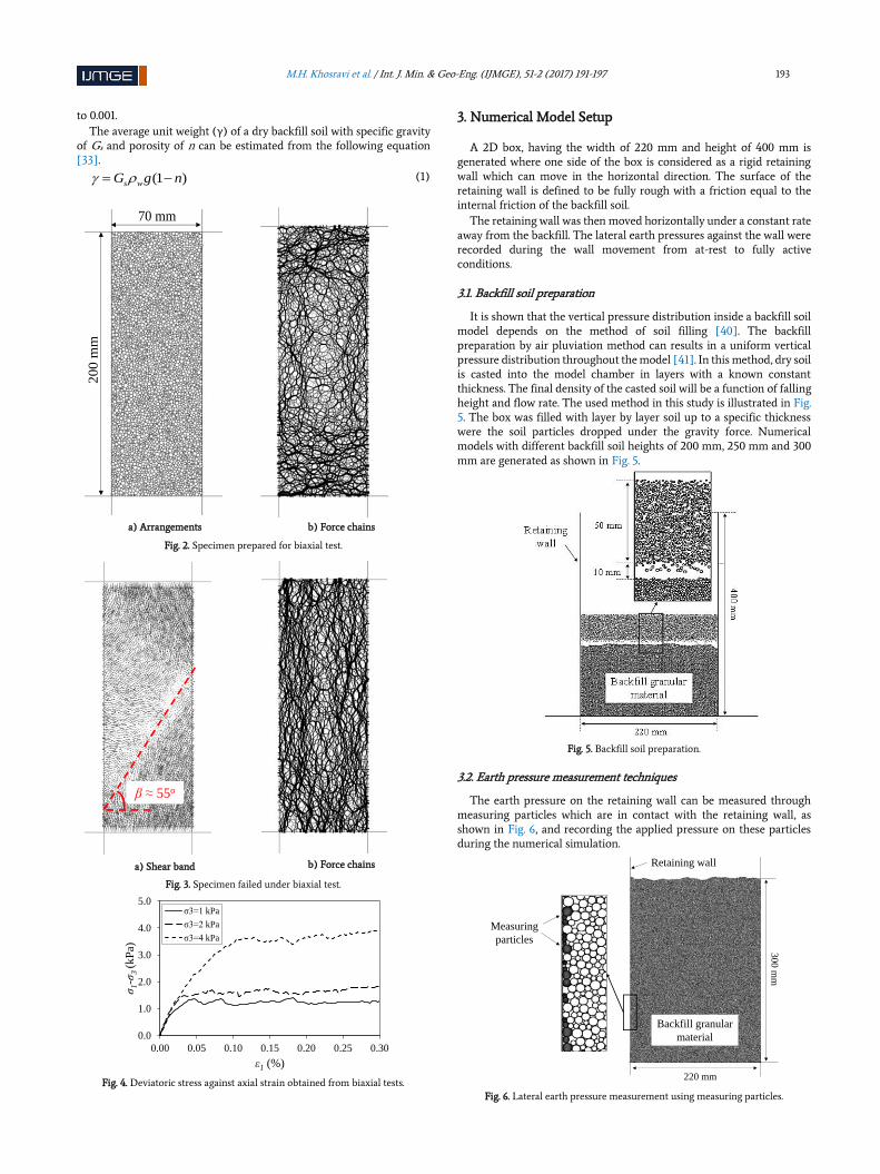
A 2D box, having the width of 220 mm and height of 400 mm is generated where one side of the box is considered as a rigid retaining wall which can move in the horizontal direction. The surface of the retaining wall is defined to be fully rough with a friction equal to the internal friction of the backfill soil.
The retaining wall was then moved horizontally under a constant rate away from the backfill. The lateral earth pressures against the wall were recorded during the wall movement from at-rest to fully active conditions.
3.1. Backfill soil preparation
It is shown that the vertical pressure distribution inside a backfill soil model depends on the method of soil filling [40]. The backfill preparation by air pluviation method can results in a uniform vertical pressure distribution throughout the model [41]. In this method, dry soil is casted into the model chamber in layers with a known constant thickness. The final density of the casted soil will be a function of falling height and flow rate. The used method in this study is illustrated in Fig. 5. The box was filled with layer by layer soil up to a specific thickness were the soil particles dropped under the gravity force. Numerical models with different backfill soil heights of 200 mm, 250 mm and 300 mm are generated as shown in Fig. 5.
Fig. 5. Backfill soil preparation.
3.2. Earth pressure measurement techniques
The earth pressure on the retaining wall can be measured through measuring particles which are in contact with the retaining wall, as shown in Fig. 6, and recording the applied pressure on these particles during the numerical simulation.
Fig. 6. Lateral earth pressure measurement using measuring particles.
70 mm
200
mm
β ≈ 55o
0.0
1.0
2.0
3.0
4.0
5.0
0.00 0.05 0.10 0.15 0.20 0.25 0.30
σ1-σ
3 (kP
a)
ε1 (%)
σ3=1 kPa
σ3=2 kPa
σ3=4 kPa
Measuring
particles
Retaining wall
30
0 m
m
220 mm
Backfill granular
material

194 M.H. Khosravi et al. / Int. J. Min. & Geo-Eng. (IJMGE), 51-2 (2017) 191-197
The absolute values of the recorded applied forces on the measuring particles are illustrated in Fig. 7 when the retaining wall is at rest (just after backfilling soil in the box) and under active conditions with some horizontal wall movements of 1 mm and 2 mm.
It can be clearly seen that the reaction forces recorded by measuring particles have no rational trend and a random distribution of forces can be observed. This behavior is related to the fact that during preparation of the backfill soil and also during the wall movement under active condition, the measuring particles are not all well-connected to the retaining wall which is due to the random size and also random position of particles. Therefore, measurement of earth pressure using the particles in vicinity of the retaining wall cannot provide acceptable results.
a) Wall at rest
b) Wall movement of 1 mm c) Wall movement of 2 mm
Fig. 7. Force recorded by measuring particles at rest and during the wall movement.
To overcome this problem, segmented measurement walls are used. The rigid retaining wall with the height of 400 mm is divided into 40 segmented rigid walls, each of them has a height of 10 mm as illustrated in Fig. 8. Each of these mini-walls acts as a pressure cell in which the lateral reaction force applied from soil onto these mini-walls are recorded to measure the lateral earth pressure. The average value of lateral earth pressure on each 4 segmented walls are considered as one recording point as indicated in Fig. 8. To observe the influence of soil arching at the lower corner of the retaining wall, the lateral earth pressure on the segmented wall located at the lower corner (PS0) is also recorded individually.
4. Results and Discussions
4.1. At-rest lateral earth pressure
Variation of the lateral earth pressure during backfilling process for a model with the target backfill height of 300 mm is shown in Fig. 9. As the height of backfill soil behind the retaining wall increases, the lateral earth pressure on the segmented walls increases gradually.
Fig. 8. Lateral earth pressure measurement using rigid segmented walls
(dimensions are in millimeters).
Fig. 9. Variation of the lateral earth pressure during backfilling process for a
target backfill height of 300 mm. The lateral earth pressure distribution against the backfill height is
shown in Fig. 10. The lateral earth pressure and backfill height in Fig. 9 and Fig. 10 are normalized by γH and H respectively, where γ is the unit weight of the backfill soil and H is the backfill height.
Fig. 10 demonstrates that using the air pluviation method in simulation of the backfill, results in a nearly linear pressure distribution on the wall except for the lower corner of the wall due to soil arching. These observations are in agreement with experimental results of Khosravi et al. [9] and numerical results of Nadukuru and Michalowski [33].
Fig. 10. Increasing the lateral earth pressure on the wall during backfilling process
for a target backfill height of 300 mm. The value of at-rest earth pressure coefficient (Ko) and active earth
pressure coefficient (Ka) for a normally consolidated sand can be approximated by the following well-known equations of Jaky [42] and Rankine [2].
1 sinoK (2)
1 sin
1 sinaK
(3)
Where ϕ represents the internal friction angle of the backfill soil.
0.00
0.10
0.20
0.30
0.40
0.50
0.60
0.70
0.80
0.90
1.00
0.00E+00 5.00E-10 1.00E-09 1.50E-09
No
rma
lize
d b
ack
fill
he
igh
t (h
/H)
Force (N)
0.00
0.10
0.20
0.30
0.40
0.50
0.60
0.70
0.80
0.90
1.00
0.00E+00 3.00E-03 6.00E-03 9.00E-03
No
rmal
ize
d b
ackf
ill h
eig
ht
(h/H
)
Force (N)
0.00
0.10
0.20
0.30
0.40
0.50
0.60
0.70
0.80
0.90
1.00
0.00E+00 3.00E-03 6.00E-03 9.00E-03
No
rma
lize
d b
ack
fill
he
igh
t (h
/H)
Force (N)
10
10
10
10
PS3
Segmented walls
300
220
PS1
PS2
PS3
PS4
PS5
PS6
PS0
PS7
Retaining wall
Backfill granular
material
40
40
40
40
40
40
40
20
0.00
0.10
0.20
0.30
0.40
0.50
0.60
0.70
0.80
0.00 0.10 0.20 0.30 0.40 0.50 0.60 0.70 0.80 0.90 1.00
No
rmal
ized
lat
eral
str
ess
(σh/γ
H)
Normalized backfill height (h/H)
PS0 PS1 PS2 PS3
PS4 PS5 PS6 PS7
0
0.1
0.2
0.3
0.4
0.5
0.6
0.7
0.8
0.9
1
0.00 0.20 0.40 0.60 0.80 1.00
Norm
aliz
ed b
ack
fill
hei
gh
t (h
/H)
Normalized lateral stress (σh/γH)
h/H=0.2
h/H=0.4
h/H=0.6
h/H=0.8
h/H=1.0
M.H. Khosravi et al. / Int. J. Min. & Geo-Eng. (IJMGE), 51-2 (2017) 191-197 195
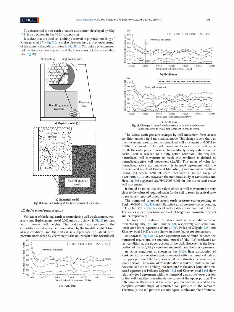
The theoretical at-rest earth pressure distribution developed by Jaky [42] is also plotted in Fig. 10 for comparison.
It is clear that the local soil arching observed in physical modeling of Khosravi et al. [9] (Fig. 11(a)) is also observed here at the lower corner of the numerical model as shown in Fig. 11(b). This micro phenomenon reduces the at-rest earth pressure at the lower corner of the wall models (see Fig. 10).
a) Physical model [9].
b) Numerical model
Fig. 11. Local soil arching at the lower corner of the model.
4.2. Active lateral earth pressure
Variations of the lateral earth pressure during wall displacement, with a constant displacement rate of 0.002 mm/s, are shown in Fig. 12 for tests with different wall heights. The horizontal axis represents the cumulative wall displacement normalized by the backfill height H from at-rest condition, and the vertical axis represents the lateral earth pressure normalized by γH where γ is the unit weight of the backfill soil.
a) H=200 mm
b) H=250 mm
c) H=300 mm
Fig. 12. Changes in lateral earth pressure with wall displacement (Dis represents the wall displacement in millimeters).
The lateral earth pressure changes by wall movement from at-rest condition under a rigid translational mode. This change is very sharp at the movement onset up to the normalized wall movement of 0.0002 to 0.0005. Increment of the wall movement beyond this critical value results the earth pressure reached to a relatively steady state where the backfill soil is reached to a fully active condition. The required normalized wall movement to reach this condition is defined as normalized active wall movement (Δxa/H). This range of value for normalized active wall movement is in good agreement with the experimental results of Fang and Ishibashi [3] and numerical results of Chang [5] where both of them measured a similar range of Δxa/H=0.0003-0.0005. However, the numerical study of Matsuzawa and Hazarika [4] suggested Δxa/H=0.0005-0.001 for the normalized active wall movement.
It should be noted that the values of active wall movement are very close to the values of required strain for the soil to reach its critical state in previously reported biaxial tests.
The numerical values of at-rest earth pressure (corresponding to Dis/H=0.0000 in Fig. 12) and fully active earth pressure (corresponding to Dis/H=0.0030 in Fig. 12) for all wall models are summarized in Fig. 13. The values of earth pressure and backfill height are normalized by γH and H, respectively.
The linear distributions for at-rest and active conditions were predicted by Jaky [42] and Rankine [2], respectively, and some non-linear arch-based equations (Handy [20], Paik and Salgado [23] and Khosravi et al. [24]) are also shown in these figures for comparison.
As shown in Fig. 13(a), a good agreement can be found between the numerical results and the analytical model of Jaky [42] conducted at-rest condition at the upper portion of the wall. However, at the lower portion of the wall, Jaky’s equation underestimates the lateral pressure.
At active condition, as shown in Fig. 13(b), liner distribution of Rankine [2] has a relatively good agreement with the numerical data at the upper portion of the wall, however, it overestimates the values at the lower portion. The reason of overestimation is that the Rankine method does not take the soil arching into account. On the other hand, the arch-based equations of Paik and Salgado [23] and Khosravi et al. [24] show relatively good agreement with the numerical data at the lower portion of the wall, but they overestimate the values at the upper portion. The difference in these data at the upper portion may be related to the complete circular shape of simulated soil particles in the software. Technically, the soil particles are not typical circles and their frictional
Rough wall surface
Backfill granular
material
Soil arching
Retaining
wall
Backfill granular
material
Soil arching
Rough wall
surface
0.00
0.10
0.20
0.30
0.40
0.50
0.60
0.70
0.0000 0.0005 0.0010 0.0015 0.0020 0.0025 0.0030
No
rmali
zed
late
ral
stre
ss (σ
h/γ
H)
Normalized wall displacement (Dis/H)
PS1 PS2 PS3 PS4 PS5
Active wall movement
0.00
0.10
0.20
0.30
0.40
0.50
0.60
0.70
0.80
0.0000 0.0005 0.0010 0.0015 0.0020 0.0025 0.0030
No
rmal
ized
lat
eral
str
ess
(σh/γ
H)
Normalized wall displacement (Dis/H)
PS1 PS2 PS3 PS4 PS5 PS6
Active wall movement
0.00
0.10
0.20
0.30
0.40
0.50
0.60
0.70
0.80
0.0000 0.0005 0.0010 0.0015 0.0020 0.0025 0.0030
No
rmal
ized
lat
eral
str
ess
(σh/γ
H)
Normalized wall displacement (Dis/H)
PS1 PS2 PS3 PS4 PS5 PS6 PS7
Active wall movement

196 M.H. Khosravi et al. / Int. J. Min. & Geo-Eng. (IJMGE), 51-2 (2017) 191-197
resistance is not only due to internal friction, but also due to interlocking.
a) At-rest state
b) Active state
Fig. 13. Lateral earth pressure distributions on the retaining wall.
The distribution predicted by Handy [20] shows a poor agreement, both at the lower and upper portions of the wall. According to Paik and Salgado [23], the reason for this disagreement is that Handy [20] did not consider the dependency of vertical and horizontal stresses on soil’s friction angle in his derivation.
It can be seen that both the linear classical and the non-linear arch-based theories overestimate the total active thrust on the retaining wall. However, considering the overturning moment, the overestimation of the non-linear arch-based theory is on the safe side while the overestimation of the linear classical theory is on the unsafe side.
5. Conclusions
This study confirms the arching phenomenon behind the retaining walls and demonstrates the ability of PFC2D code as a discrete element method in simulation of the cohesionless granular material and arching effect. In simulation of cohesionless sandy soils in PFC2D, using the circular particles defined in the software as individual soil particles, lack
of interlocking between the soil particles will result in a lower internal friction angle for the soil than the expected values. Therefore, it is recommended to use a combination of clumped particles in simulation. The backfill soil reaches to its critical state at a horizontal wall movement almost corresponding to axial strain in biaxial tests conducted on the same soil under equivalent confining pressures. Under at-rest condition, the equation of Jaky [42] properly predicts the numerical results at the upper portion of the wall, but underestimates the lateral pressure at its lower portion. The phenomenon of arching at the lower corner of the wall results in a reduction in lateral earth pressure on the toe of the wall even under at-rest condition before applying any movement to the wall. Under active condition, liner distribution of Rankine [2] shows a good prediction at the upper portion but overestimates the earth pressure at the lower portion of the wall. On the other hand, predictions from arch-based equations are acceptable only for the lower portion of the wall.
REFRENCES
[1] Coulomb, C. A. (1776). Essai sur une application des règles de maximis & minimis à quelques problèmes de statique. relatifs à l'architecture. Mémoires de Mathématique et de Physique de l'Académie, 7, 343-82.
[2] Rankine, W. J. M. (1857). On the stability of loose earth. Philosophical Transactions of the Royal Society of London, 147, 9-27.
[3] Fang, Y., & Ishibashi, I. (1986). Static earth pressures with various wall movements. Journal of Geotechnical Engineering-ASCE, 112(3), 317-33.
[4] Matsuzawa, H., & Hazarika, H. (1996). Analysis of active earth pressure against rigid retaining wall subjected to different modes of movement. Soils and Foundations, 36(3), 51-65.
[5] Chang, M. F. (1997). Lateral earth pressures behind rotating walls. Canadian Geotechnical Journal, 34(4), 498-509.
[6] Take, W. A., & Valsangkar, A. J. (2001). Earth pressures on unyielding retaining walls of narrow backfill width. Canadian Geotechnical Journal, 38(6), 1220-30.
[7] O’Neal, T. S., & Hagerty, D. J. (2011). Earth pressures in confined cohesionless backfill against tall rigid walls — a case history. Canadian Geotechnical Journal, 48(8), 1188-97.
[8] Iskander, M., Chen, Z., Omidbar, M., Guzman, I., & Elsherif, O. (2013). Active static and seismic earth pressure for c-ϕ soils. Soils and Foundations, 53 (5), 639-652.
[9] Khosravi, M. H., Pipatpongsa, T., & Takemura, J. (2013). Experimental analysis of earth pressure against rigid retaining walls under translation mode. Géotechnique, 63(12), 1020-28.
[10] Zeitschr, d. (1895). Versuche über Getreidedruck in Silozellen (Texts on grain pressure in silos). Vereines deutscher Ingenieure, 39, 1045-49.
[11] Marston, A., & Anderson, A. O. (1913). The theory of loads on pipes in ditches and tests of cement and clay drain tile and sewer pipe. Bulletins of the Engineering Experiment Station, 31, 1-181.
[12] Terzaghi, K. (1934). Large retaining-wall tests. Engineering News-Record, 112(5, 8, 10, 13, 16. 23), 136-140, 259-262, 316-318, 403-406, 503-508, 747.
[13] Getzler, Z., Komornik, A., & Mazurik, A. (1968). Model study on arching above buried structures. Journal of the Soil Mechanics and Foundations Division- ASCE, 94(5), 1114-23.
[14] Walker, D. M. (1966). An approximate theory for pressures and arching in hoppers. Chemical Engineering Science, 21(11), 975-97.
[15] Walters, J. K. (1973). A theoretical analysis of stresses in axially-symmetric hoppers and bunkers. Chemical Engineering Science, 28(3), 779-89.
0
0.1
0.2
0.3
0.4
0.5
0.6
0.7
0.8
0.9
1
0.00 0.20 0.40 0.60 0.80
No
rmal
ized
bac
kfi
ll h
eig
ht
(h/H
)
Normalized lateral stress (σh/γH)
H=200 mm
H=250 mm
H=300 mm
Jaky [42]
0
0.1
0.2
0.3
0.4
0.5
0.6
0.7
0.8
0.9
1
0.00 0.20 0.40 0.60
No
rmal
ized
bac
kfi
ll h
eig
ht
(h/H
)
Normalized lateral stress (σh/γH)
H=200 mm
H=250 mm
H=300 mm
Rankine [2]
Handy [20]
Khosravi et al.
[24]
Paik &
Salgado [23]

M.H. Khosravi et al. / Int. J. Min. & Geo-Eng. (IJMGE), 51-2 (2017) 191-197 197
[16] Wang, W. L., & Yen, B. C. (1974). Soil arching in slopes. Journal of the Geotechnical Engineering Division-ASCE, 100(1), 61-78.
[17] Khosravi, M. H., Pipatpongsa, T., Takahashi, A., & Takemura, J. (2011). Arch action over an excavated pit on a stable scarp investigated by physical model tests. Soils and Foundations, 51(4), 723-35.
[18] Khosravi, M. H., Tang, T., Pipatpongsa, P., Takemura, J., & Doncommul, P. (2012). Performance of counterweight balance on stability of undercut slope evaluated by physical modeling. International Journal of Geotechnical Engineering, 6, 193-205.
[19] Khosravi, M. H., Takemura, J., Pipatpongsa, T., & Amini, M. (2016). In-flight Excavation of Slopes with Potential Failure Planes. Journal of Geotechnical and Geoenvironmental Engineering, doi:10.1061/(ASCE)GT.1943-5606.0001439
[20] Handy, R. L. (1985). The arch in soil arching. Journal of Geotechnical Engineering- ASCE, 111(3), 302-18.
[21] Harrop-Williams, K. (1989). Arch in soil arching. Journal of Geotechnical Engineering – ASCE, 115(3), 415-19.
[22] Wang, Y. Z. (2000). Distribution of earth pressure on a retaining wall. Geotechnique, 50(1), 83-88.
[23] Paik, K. H., & Salgado, R. (2003). Estimation of active earth pressure against rigid retaining walls considering arching effects. Geotechnique, 53(7), 643-53.
[24] Khosravi, M. H., Pipatpongsa, T., & Takemura, J. (2016). Theoretical analysis of earth pressure against rigid retaining walls under translation mode. Soils and Foundations, 56(4), 664-75.
[25] Tsagareli, Z. V. (1965). Experimental investigation of the pressure of a loose medium on retaining walls with a vertical back face and horizontal backfill surface. Soil Mechanics and Foundation Engineering, 2(4), 197-200.
[26] Sherif, M.A., & Fang, Y. (1984). Dynamic earth pressures on walls rotating about the top. Soils and Foundations, 24(4), 109-117.
[27] Niedostatkiewicz, M., Lesniewska, D., & Tejchman, J. (2011). Experimental analysis of shear zone patterns in cohesionless for earth pressure problems using particle image velocimetry. Strain, 47(S2), 218–31.
[28] Loukidis, D., & Salgado, R. (2012) Active pressure on gravity walls supporting purely frictional soils. Canadian Geotechnical Journal, 49(1), 78-97.
[29] Worden, F.T., & Achmus, M. (2013). Numerical modeling of three dimensional active earth pressure acting on rigid walls. Computers and Geotechnics, 51, 83-90.
[30] Chen, J.J., Lei, H., & Wang, J.H. (2014). Numerical Analysis of
the installation effect of diphragm walls in saturated soft clay. Acta Geotechnica, 9(6), 981-991.
[31] Li, M. G., Chen, J. J. & Wang, J. H. (2017). Arching effect on lateral pressure of confined granular materail: numerical and theoretical analysis. Granular Matter, published online. DOI: 10.1007/s10035-017-0700-2.
[32] Itasca Consulting Group Inc (2008) PFC2D manual. version 4.0. Minneapolis. Minnesota.
[33] Nadukuru, S., & Michalowski, R. (2012). Arching in distribution of active load on retaining walls. Journal of Geotechnical and Geoenvironmental Engineering, 138(5), 575-84.
[34] Rui, R., van Tol, F., Xia, X-L., van Eekelen, S., Hu, G., & Xia, Y-y. (2016). Evolution of soil arching; 2D DEM simulations. Computers and Geotechnics, 73, 199-209.
[35] Mas Ivars, D., Pierce, M. E., Darcel, C., Reyes-Montes, J., Potyondy, D. O., & Young, R. P. (2011). The synthetic rock mass approach for jointed rock mass modelling. International Journal of Rock Mechanics & Mining Sciences, 48(2), 219-44.
[36] Bahaaddini, M., Sharrock, G., & Hebblewhite, B. K. (2013a). Numerical investigation of the effect of joint geometrical parameters on the mechanical properties of a non-persistent jointed rock mass under uniaxial compression. Computers and Geotechnics, 49, 206-25.
[37] Bahaaddini, M., Sharrock, G., & Hebblewhite, B. K. (2013b). Numerical direct shear tests to model the shear behaviour of rock joints. Computers and Geotechnics, 51, 101-15.
[38] Bahaaddini, M., Hagan, P. C., Mitra, R., & Hebblewhite, B. K. (2016a). Numerical study of the mechanical behaviour of non-persistent jointed rock masses. International Journal of Geomechanics, 16(1), 040150351-10.
[39] Bahaaddini, M., Hagan, P. C., Mitra, R., & Khosravi, M. H. (2016b). Experimental and numerical study of asperity degradation in the direct shear test. Engineering Geology, 204, 41-52.
[40] Thay, S., Kitakata, S., Pipatpongsa, T., & Takahashi, A. (2012). Measurements of vertical pressure profile beneath a planar valley of loose sand and its estimation based on self-similar solution of elliptic equation system. Journal of Japan Society of Civil Engineers. Ser. A2 (Applied Mechanics), 68(2), I21-32.
[41] Khosravi, M. H. (2012). Arching effect in geomaterials with applications to retaining walls and undercut slopes. Ph.D. dissertation. Tokyo Institute of Technology. Tokyo
[42] Jáky, J. (1948). Earth pressure in silos. Proceedings of the 2nd International Conference on Soil Mechanics and Foundation Engineering, ICSMFE1, 103-7.