Dell OptiPlex 3050 All-in-One Owner's Manual OptiPlex 3050 All-in-One Owner's Manual Regulatory...
66
Dell OptiPlex 3050 All-in-One Owner's Manual Regulatory Model: W18B Regulatory Type: W18B001
Transcript of Dell OptiPlex 3050 All-in-One Owner's Manual OptiPlex 3050 All-in-One Owner's Manual Regulatory...
Dell OptiPlex 3050 All-in-OneOwner's Manual
Regulatory Model: W18BRegulatory Type: W18B001

Notes, cautions, and warnings
NOTE: A NOTE indicates important information that helps you make better use of your product.
CAUTION: A CAUTION indicates either potential damage to hardware or loss of data and tells you how to avoid the problem.
WARNING: A WARNING indicates a potential for property damage, personal injury, or death.
© 2017 Dell Inc. or its subsidiaries. All rights reserved. Dell, EMC, and other trademarks are trademarks of Dell Inc. or its subsidiaries. Other trademarks may be trademarks of their respective owners.
2017 - 02
Rev. A00
Contents
1 Working on your computer............................................................................................................................. 7Safety instructions............................................................................................................................................................. 7Before working inside your computer.............................................................................................................................. 7Turning off your computer................................................................................................................................................ 8
Turning off your computer — Windows 10...............................................................................................................8Turning off your computer — Windows 7.................................................................................................................8
After working inside your computer.................................................................................................................................8Important Information........................................................................................................................................................8
2 Removing and installing components............................................................................................................. 9Stand................................................................................................................................................................................... 9
Removing easel stand..................................................................................................................................................9Installing easel stand...................................................................................................................................................10
Optical drive...................................................................................................................................................................... 10Removing optical drive...............................................................................................................................................10Installing optical drive................................................................................................................................................. 10
Back cover..........................................................................................................................................................................11Removing back cover................................................................................................................................................. 11Installing back cover....................................................................................................................................................11
Intrusion switch.................................................................................................................................................................12Removing intrusion switch.........................................................................................................................................12Installing intrusion switch........................................................................................................................................... 12
System board shield......................................................................................................................................................... 13Removing system board shield..................................................................................................................................13Installing system board shield.................................................................................................................................... 13
Hard drive.......................................................................................................................................................................... 14Removing hard drive...................................................................................................................................................14Installing hard drive ....................................................................................................................................................14
Cable holder...................................................................................................................................................................... 15Removing cable holder...............................................................................................................................................15Installing cable holder ................................................................................................................................................ 15
Memory module................................................................................................................................................................ 16Removing memory module........................................................................................................................................16Installing memory module.......................................................................................................................................... 16
Coin cell battery................................................................................................................................................................ 17Removing coin cell battery.........................................................................................................................................17Installing coin cell battery........................................................................................................................................... 17
Solid State Drive (SSD)....................................................................................................................................................18Removing Solid State Drive (SSD) card...................................................................................................................18Installing Solid State Drive (SSD) card..................................................................................................................... 18
WLAN card........................................................................................................................................................................ 19Removing WLAN card................................................................................................................................................19Installing WLAN card.................................................................................................................................................. 19
Contents 3
Heat sink........................................................................................................................................................................... 20Removing heat sink .................................................................................................................................................. 20Installing heat sink .....................................................................................................................................................20
System fan.........................................................................................................................................................................21Removing system fan (35 W optional).................................................................................................................... 21Installing system fan (35 W optional).......................................................................................................................21Removing system fan (65 W).................................................................................................................................. 22Installing system fan (65 W).....................................................................................................................................22
Power and On-Screen Display........................................................................................................................................23Removing power and On-Screen Display (OSD) board ....................................................................................... 23Installing power and On-Screen Display (OSD) board...........................................................................................23
Speaker............................................................................................................................................................................. 24Removing speaker .....................................................................................................................................................24Installing speaker........................................................................................................................................................25
Graphic card assembly.................................................................................................................................................... 25Removing graphics card assembly...........................................................................................................................25Installing graphics card assembly............................................................................................................................. 26
Processor.......................................................................................................................................................................... 26Removing processor..................................................................................................................................................26Installing processor.....................................................................................................................................................27
System board....................................................................................................................................................................27Removing system board............................................................................................................................................ 27Installing system board.............................................................................................................................................. 30
Chassis frame...................................................................................................................................................................30Removing chassis frame........................................................................................................................................... 30Installing chassis frame..............................................................................................................................................32
Display assembly.............................................................................................................................................................. 33Removing display assembly...................................................................................................................................... 33Installing display assembly.........................................................................................................................................34
Camera..............................................................................................................................................................................35Removing camera...................................................................................................................................................... 35Installing camera.........................................................................................................................................................36
3 Technology and components........................................................................................................................37Processors.........................................................................................................................................................................37
Skylake processor.......................................................................................................................................................37Kaby Lake — 7th Generation Intel Core processors............................................................................................. 38Identifying processors in Windows 7....................................................................................................................... 38Identifying processors in Windows 10..................................................................................................................... 38Verifying the processor usage in Task Manager.....................................................................................................39Verifying the processor usage in Resource Monitor..............................................................................................39
Chipsets............................................................................................................................................................................ 39Identifying chipset in Device Manager on Windows 7...........................................................................................39Identifying the chipset in Device Manager on Windows 10..................................................................................39Intel HD Graphics drivers.......................................................................................................................................... 39Downloading the chipset driver............................................................................................................................... 40Downloading drivers.................................................................................................................................................. 40
4 Contents
Display options................................................................................................................................................................. 40Identifying the display adapter................................................................................................................................. 40Changing the screen resolution................................................................................................................................40Adjusting brightness in Windows 7...........................................................................................................................41Adjusting brightness in Windows 10......................................................................................................................... 41Connecting to external display devices....................................................................................................................41
Intel HD Graphics .............................................................................................................................................................41Intel HD Graphics drivers........................................................................................................................................... 41
Hard drive options............................................................................................................................................................42Identifying the hard drive in Windows 7..................................................................................................................42Identifying the hard drive in Windows 10................................................................................................................ 42Entering BIOS setup.................................................................................................................................................. 42
USB features.................................................................................................................................................................... 42USB 3.0/USB 3.1 Gen 1 (SuperSpeed USB)...........................................................................................................42Speed...........................................................................................................................................................................43Applications.................................................................................................................................................................44Compatibility...............................................................................................................................................................44
Memory features..............................................................................................................................................................44Verifying system memory in Windows 10 and Windows 7 ...................................................................................45Verifying system memory in setup...........................................................................................................................45DDR4........................................................................................................................................................................... 45Testing memory using ePSA.....................................................................................................................................46
Realtek HD audio drivers.................................................................................................................................................46
4 System setup...............................................................................................................................................48BIOS Overview.................................................................................................................................................................48
Boot menu.................................................................................................................................................................. 48System setup options................................................................................................................................................48
5 Technical specifications............................................................................................................................... 57System specifications......................................................................................................................................................57Memory specifications.................................................................................................................................................... 57Video specifications.........................................................................................................................................................58Audio specifications.........................................................................................................................................................58Communication specifications....................................................................................................................................... 58Cards specifications.........................................................................................................................................................59Display specifications.......................................................................................................................................................59Drives specifications........................................................................................................................................................59Port and connector specifications.................................................................................................................................59Power specifications....................................................................................................................................................... 60Camera specifications..................................................................................................................................................... 60Stand specifications........................................................................................................................................................ 60Physical specifications.....................................................................................................................................................60Environmental specifications...........................................................................................................................................61
6 Troubleshooting........................................................................................................................................... 62Enhanced Pre-Boot System Assessment (ePSA) diagnostics...................................................................................62
Contents 5

Running the ePSA diagnostics....................................................................................................................................... 62LCD built in self test (BIST)............................................................................................................................................62
Invoking BIST with user modes................................................................................................................................64OSD toggle................................................................................................................................................................. 64ePSA............................................................................................................................................................................64
7 Contacting Dell............................................................................................................................................ 66
6 Contents
Working on your computer
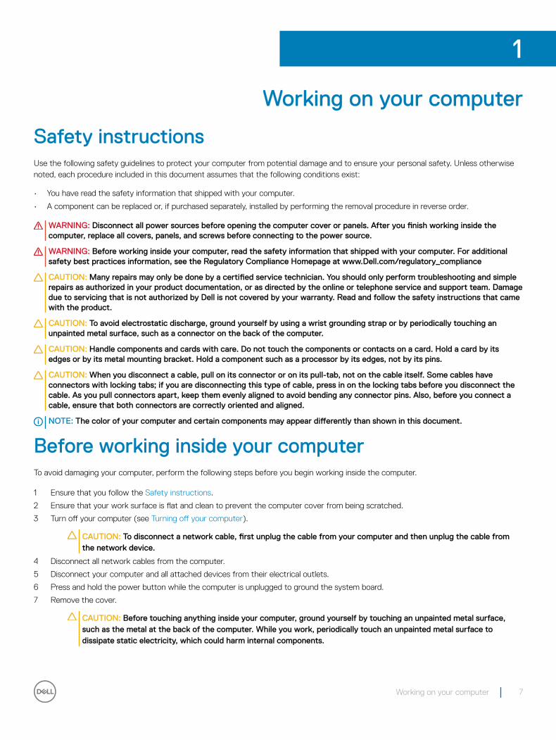
Safety instructionsUse the following safety guidelines to protect your computer from potential damage and to ensure your personal safety. Unless otherwise noted, each procedure included in this document assumes that the following conditions exist:
• You have read the safety information that shipped with your computer.
• A component can be replaced or, if purchased separately, installed by performing the removal procedure in reverse order.
WARNING: Disconnect all power sources before opening the computer cover or panels. After you finish working inside the computer, replace all covers, panels, and screws before connecting to the power source.
WARNING: Before working inside your computer, read the safety information that shipped with your computer. For additional safety best practices information, see the Regulatory Compliance Homepage at www.Dell.com/regulatory_compliance
CAUTION: Many repairs may only be done by a certified service technician. You should only perform troubleshooting and simple repairs as authorized in your product documentation, or as directed by the online or telephone service and support team. Damage due to servicing that is not authorized by Dell is not covered by your warranty. Read and follow the safety instructions that came with the product.
CAUTION: To avoid electrostatic discharge, ground yourself by using a wrist grounding strap or by periodically touching an unpainted metal surface, such as a connector on the back of the computer.
CAUTION: Handle components and cards with care. Do not touch the components or contacts on a card. Hold a card by its edges or by its metal mounting bracket. Hold a component such as a processor by its edges, not by its pins.
CAUTION: When you disconnect a cable, pull on its connector or on its pull-tab, not on the cable itself. Some cables have connectors with locking tabs; if you are disconnecting this type of cable, press in on the locking tabs before you disconnect the cable. As you pull connectors apart, keep them evenly aligned to avoid bending any connector pins. Also, before you connect a cable, ensure that both connectors are correctly oriented and aligned.
NOTE: The color of your computer and certain components may appear differently than shown in this document.
Before working inside your computerTo avoid damaging your computer, perform the following steps before you begin working inside the computer.
1 Ensure that you follow the Safety instructions.
2 Ensure that your work surface is flat and clean to prevent the computer cover from being scratched.
3 Turn off your computer (see Turning off your computer).
CAUTION: To disconnect a network cable, first unplug the cable from your computer and then unplug the cable from the network device.
4 Disconnect all network cables from the computer.
5 Disconnect your computer and all attached devices from their electrical outlets.
6 Press and hold the power button while the computer is unplugged to ground the system board.
7 Remove the cover.
CAUTION: Before touching anything inside your computer, ground yourself by touching an unpainted metal surface, such as the metal at the back of the computer. While you work, periodically touch an unpainted metal surface to dissipate static electricity, which could harm internal components.
1
Working on your computer 7
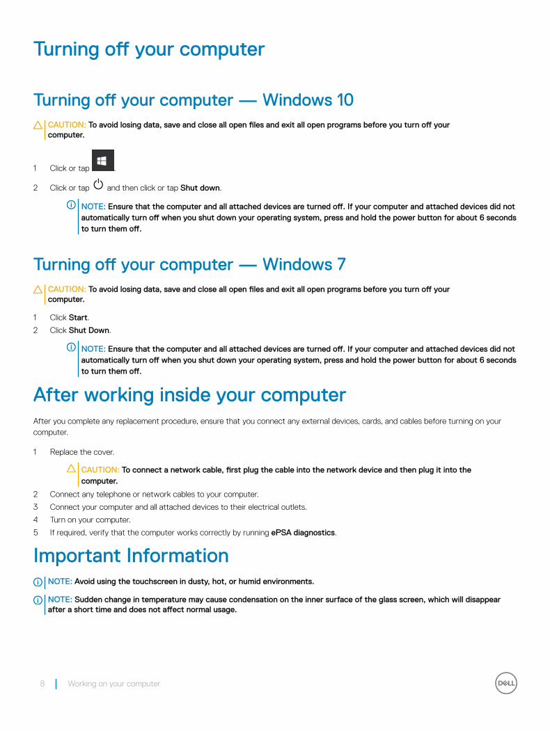
Turning off your computer
Turning off your computer — Windows 10CAUTION: To avoid losing data, save and close all open files and exit all open programs before you turn off your computer.
1 Click or tap .
2 Click or tap and then click or tap Shut down.
NOTE: Ensure that the computer and all attached devices are turned off. If your computer and attached devices did not automatically turn off when you shut down your operating system, press and hold the power button for about 6 seconds to turn them off.
Turning off your computer — Windows 7CAUTION: To avoid losing data, save and close all open files and exit all open programs before you turn off your computer.
1 Click Start.
2 Click Shut Down.
NOTE: Ensure that the computer and all attached devices are turned off. If your computer and attached devices did not automatically turn off when you shut down your operating system, press and hold the power button for about 6 seconds to turn them off.
After working inside your computerAfter you complete any replacement procedure, ensure that you connect any external devices, cards, and cables before turning on your computer.
1 Replace the cover.
CAUTION: To connect a network cable, first plug the cable into the network device and then plug it into the computer.
2 Connect any telephone or network cables to your computer.
3 Connect your computer and all attached devices to their electrical outlets.
4 Turn on your computer.
5 If required, verify that the computer works correctly by running ePSA diagnostics.
Important InformationNOTE: Avoid using the touchscreen in dusty, hot, or humid environments.
NOTE: Sudden change in temperature may cause condensation on the inner surface of the glass screen, which will disappear after a short time and does not affect normal usage.
8 Working on your computer
Removing and installing componentsThis section provides detailed information on how to remove or install the components from your computer.
Stand
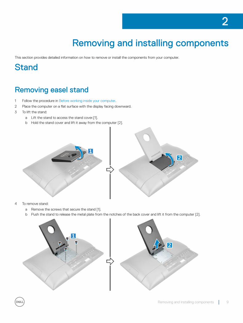
Removing easel stand1 Follow the procedure in Before working inside your computer.
2 Place the computer on a flat surface with the display facing downward.
3 To lift the stand:
a Lift the stand to access the stand cover.[1].b Hold the stand cover and lift it away from the computer [2].
4 To remove stand:
a Remove the screws that secure the stand [1].b Push the stand to release the metal plate from the notches of the back cover and lift it from the computer [2].
2
Removing and installing components 9
Installing easel stand1 Position the stand to allow the metal plate tab to align with the notches on the back cover.
2 Replace the M4x7 screws to secure the stand to the computer.
3 Place the cover on the metal plate until snaps in.
4 Follow the procedure in After working inside your computer.
Optical drive
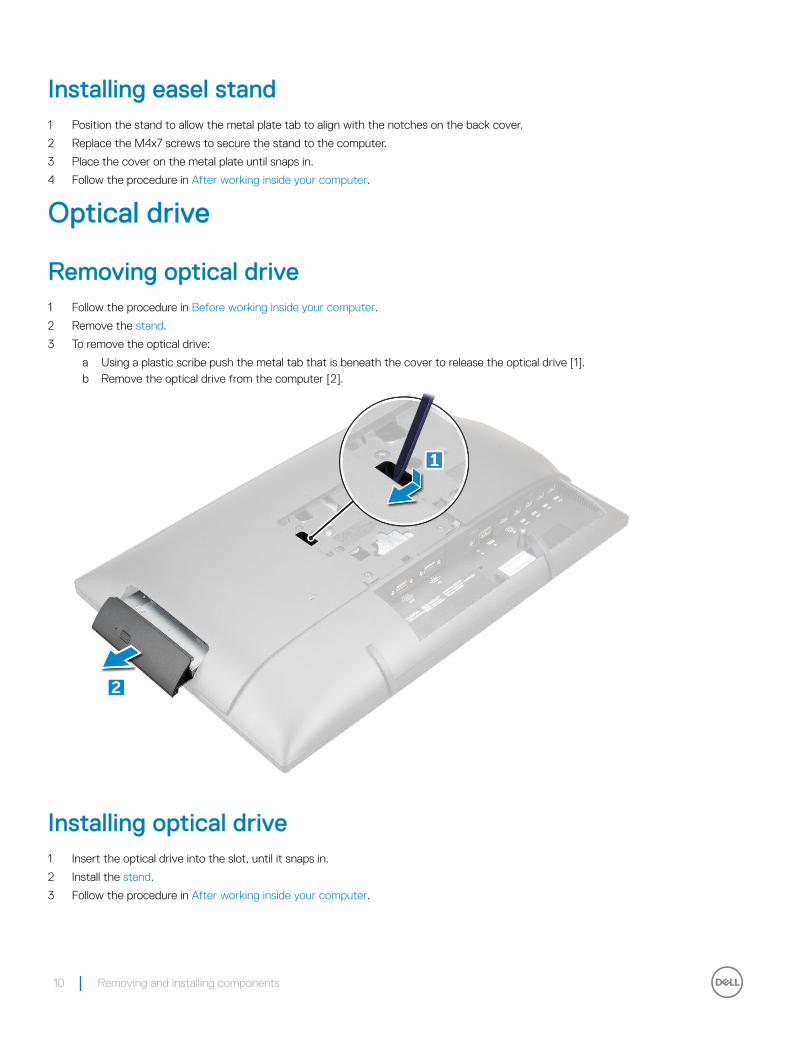
Removing optical drive1 Follow the procedure in Before working inside your computer.
2 Remove the stand.
3 To remove the optical drive:
a Using a plastic scribe push the metal tab that is beneath the cover to release the optical drive [1].b Remove the optical drive from the computer [2].
Installing optical drive1 Insert the optical drive into the slot, until it snaps in.
2 Install the stand.
3 Follow the procedure in After working inside your computer.
10 Removing and installing components

Back cover
Removing back cover1 Follow the procedure in Before working inside your computer.
2 Remove the:
a standb optical drive
3 Pry the edges and remove the back cover optical drive slot.
NOTE: On system with POGO Intrusion feature; after replacing the system board, it is very important that technicians reassemble the back cover prior booting the system up to the SMMM service menu. The POGO intrusion feature can only be enabled when the system is in service mode at SMMM. Once exited, the SMMM can no longer be triggered and a replacement system board would be required.
Installing back cover1 Align the notches on the back cover to the holes on the computer.
2 Press the back cover until it snaps on the computer.
3 Install the:
a optical driveb stand
4 Follow the procedure in After working inside your computer.
Removing and installing components 11

Intrusion switch
Removing intrusion switch1 Follow the procedure in Before working inside your computer.
2 Remove the:
a standb optical drivec back cover
3 To remove intrusion switch:
a Turn the holder clockwise direction [1].b Lift the holder [2].c Lift the intrusion switch [3].
Installing intrusion switch1 Insert the switch on the holder on the back cover.
2 Plug the holder to intrusion switch
3 Replace the holder in direction.
4 Install the:
a back coverb optical drivec stand
5 Follow the procedure in After working inside your computer.
12 Removing and installing components

System board shield
Removing system board shield1 Follow the procedure in Before working inside your computer.
2 Remove the:
a standb optical drivec back cover
3 To remove system board shield:
a Remove the M3 0.5x5 screw that secures system board shield to the computer [1].b Lift the system board shield away from the computer [2].
Installing system board shield1 Align the system board shield with the screw holder on the computer.
2 Replace M3 0.5x5 screw to secures the system board shield to the computer.
3 Install the:
a back coverb optical drivec stand
4 Follow the procedure in After working inside your computer.
Removing and installing components 13

Hard drive
Removing hard drive1 Follow the procedure in Before working inside your computer.
2 Remove the:
a standb optical drivec back coverd system board shield
3 To remove hard drive:
a Remove the M3X3.5.5 screws that secure the hard drive to the computer [1].b Slide and remove the hard drive from the computer [2].
Installing hard drive 1 Place the hard drive on the slot and slide it in to align with the screw holders and to connect it to the connector on the system board.
2 Replace the M3X3.5 screws to secure the hard drive on the computer.
3 Install the:
a system board shieldb back coverc optical drived stand
4 Follow the procedure in After working inside your computer.
14 Removing and installing components
Cable holder
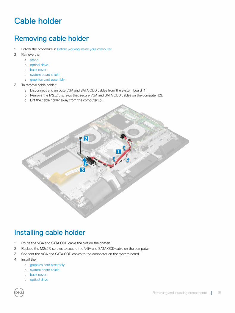
Removing cable holder1 Follow the procedure in Before working inside your computer.
2 Remove the:
a standb optical drivec back coverd system board shielde graphics card assembly
3 To remove cable holder:
a Disconnect and unroute VGA and SATA ODD cables from the system board [1]b Remove the M2x2.5 screws that secure VGA and SATA ODD cables on the computer [2].c Lift the cable holder away from the computer [3].
Installing cable holder 1 Route the VGA and SATA ODD cable the slot on the chassis.
2 Replace the M2x2.5 screws to secure the VGA and SATA ODD cable on the computer.
3 Connect the VGA and SATA ODD cables to the connector on the system board.
4 Install the:
a graphics card assemblyb system board shieldc back coverd optical drive
Removing and installing components 15
e stand
5 Follow the procedure in After working inside your computer.
Memory module
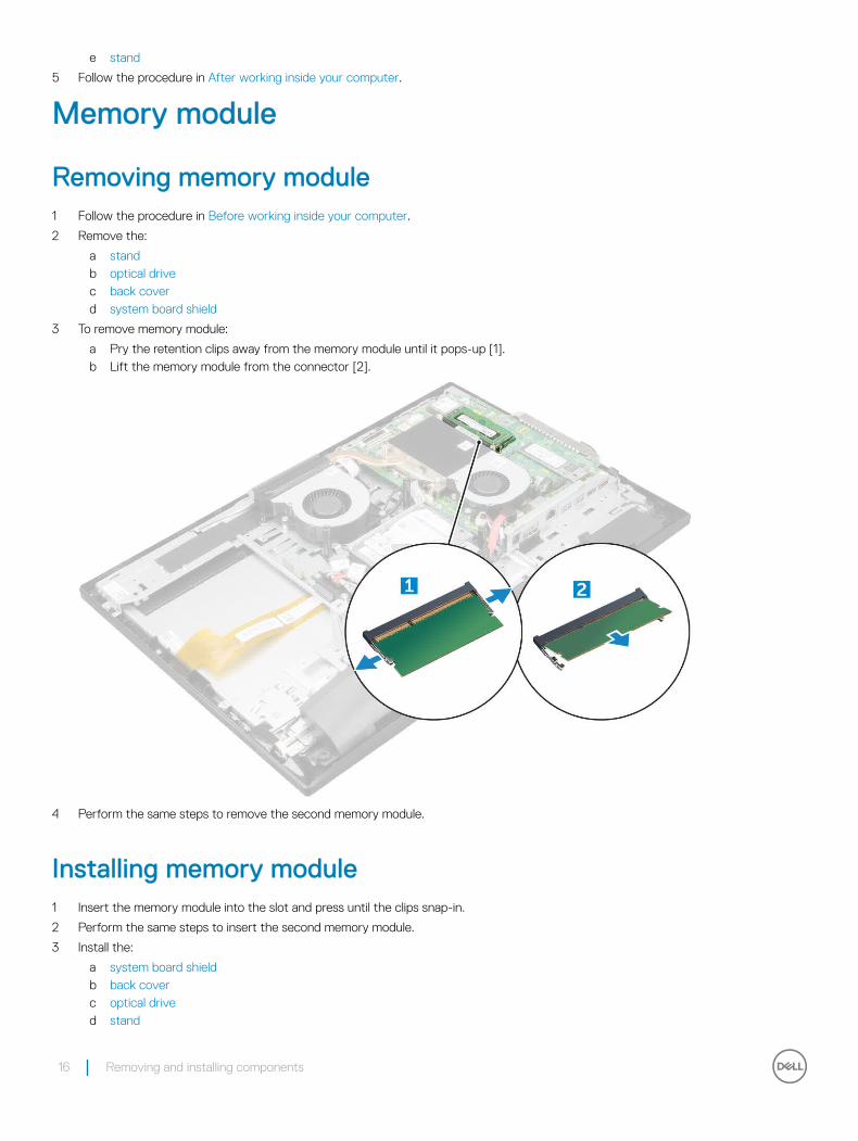
Removing memory module1 Follow the procedure in Before working inside your computer.
2 Remove the:
a standb optical drivec back coverd system board shield
3 To remove memory module:
a Pry the retention clips away from the memory module until it pops-up [1].b Lift the memory module from the connector [2].
4 Perform the same steps to remove the second memory module.
Installing memory module1 Insert the memory module into the slot and press until the clips snap-in.
2 Perform the same steps to insert the second memory module.
3 Install the:
a system board shieldb back coverc optical drived stand
16 Removing and installing components
4 Follow the procedure in After working inside your computer.
Coin cell battery
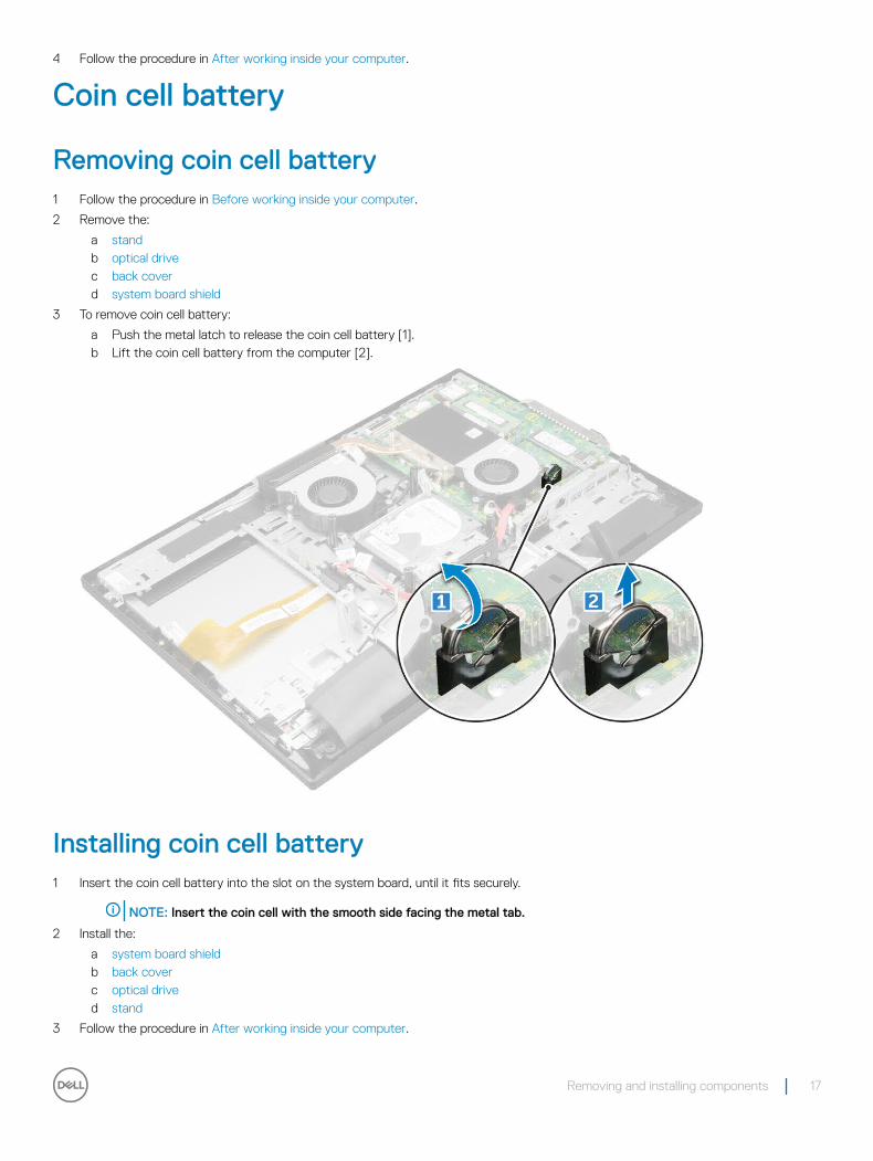
Removing coin cell battery1 Follow the procedure in Before working inside your computer.
2 Remove the:
a standb optical drivec back coverd system board shield
3 To remove coin cell battery:
a Push the metal latch to release the coin cell battery [1].b Lift the coin cell battery from the computer [2].
Installing coin cell battery1 Insert the coin cell battery into the slot on the system board, until it fits securely.
NOTE: Insert the coin cell with the smooth side facing the metal tab.
2 Install the:
a system board shieldb back coverc optical drived stand
3 Follow the procedure in After working inside your computer.
Removing and installing components 17

Solid State Drive (SSD)
Removing Solid State Drive (SSD) card1 Follow the procedure in Before working inside your computer.
2 Remove the:
a standb optical drivec back coverd system board shield
3 To remove SSD card:
a Remove the M2x2.5 screw that secures the SSD card to the system board [1].b Lift the SSD card away from the connector [2].
Installing Solid State Drive (SSD) card1 Insert the SSD card to the connector on the system board.
2 Replace the screw to secure the SSD card to the system board.
3 Install the:
a system board shieldb back coverc optical drived stand
4 Follow the procedure in After working inside your computer.
18 Removing and installing components

WLAN card
Removing WLAN card1 Follow the procedure in Before working inside your computer.
2 Remove the:
a standb optical drivec back coverd system board shield
3 To remove WLAN card:
a Disconnect the antenna cables from the connectors on the WLAN card [1].b Remove the M2x 2.5 screw that secures the WLAN card to the system board [2].c Hold the WLAN card, and pull it from the connector on the system board [3].
Installing WLAN card1 Align the WLAN card to the connector on the system board.
2 Replace the M2x2.5 screw to secure the WLAN card to the system board.
NOTE: Best practise: Connect the cables and then insert the card into the slot.
3 Connect the antenna cables to the connectors on the WLAN card.
4 Install the:
a system board shieldb back coverc optical drive
Removing and installing components 19

d stand
5 Follow the procedure in After working inside your computer.
Heat sink
Removing heat sink 1 Follow the procedure in Before working inside your computer.
2 Remove the:
a standb optical drivec back coverd system board shield
3 To remove heat sink:
a Remove the screw M2x2.5 that secures the heat sink to the chassis [1].b Loosen the captive screws that secure the heat sink to the system board [2].
NOTE: Remove the screws that secure the heat sink to the system board in the order of the callouts shown on the heat sink [1, 2, 3, 4].
c Lift the heat sink away from the computer [3].
Installing heat sink 1 Place the heat sink on the system board and align it with the screw holders.
2 Replace the screws to secure the heat sink to the system board.
NOTE: Tighten the screws that secure the heat sink to the system board in the order of the callouts shown on the heat sink [1, 2, 3, 4].
20 Removing and installing components

3 Replace the M2x2.5 screw to secure the heat sink to the chassis.
4 Install the:
a system board shieldb back coverc optical drived stand
5 Follow the procedure in After working inside your computer.
System fan
Removing system fan (35 W optional)1 Follow the procedure in Before working inside your computer.
2 Remove the:
a standb optical drivec back coverd system board shield
3 To remove system fan:
a Disconnect the system fan cable [1].b Remove the M3.5x5 screws that secure the system fan to the system board [2].c Lift the system fan away from the computer [3].
Installing system fan (35 W optional)1 Place the system fan to align with the screw holders on the chassis.
2 Replace the M3.5x5 screws to secure the system fan to the chassis.
Removing and installing components 21

3 Connect the system fan cable to the connector on the system board.
4 Install the:
a system board shieldb back coverc optical drived stand
5 Follow the procedure in After working inside your computer.
Removing system fan (65 W)1 Follow the procedure in Before working inside your computer.
2 Remove the:
a standb optical drivec back coverd system board shield
3 To remove system fan:
a Disconnect the system fan cable [1].b Remove the M3.5x5 screws that secure the system fan to the system board [2].c Lift the system fan away from the computer [3].
Installing system fan (65 W)1 Place the system fan to align with the screw holders on the chassis.
2 Replace the M3.5x5 screws to secure the system fan to the chassis.
3 Connect the system fan cable to the connector on the system board.
4 Install the:
22 Removing and installing components
a system board shieldb back coverc optical drived stand
5 Follow the procedure in After working inside your computer.
Power and On-Screen Display
Removing power and On-Screen Display (OSD) board 1 Follow the procedure in Before working inside your computer.
2 Remove the:
a standb optical drivec back cover
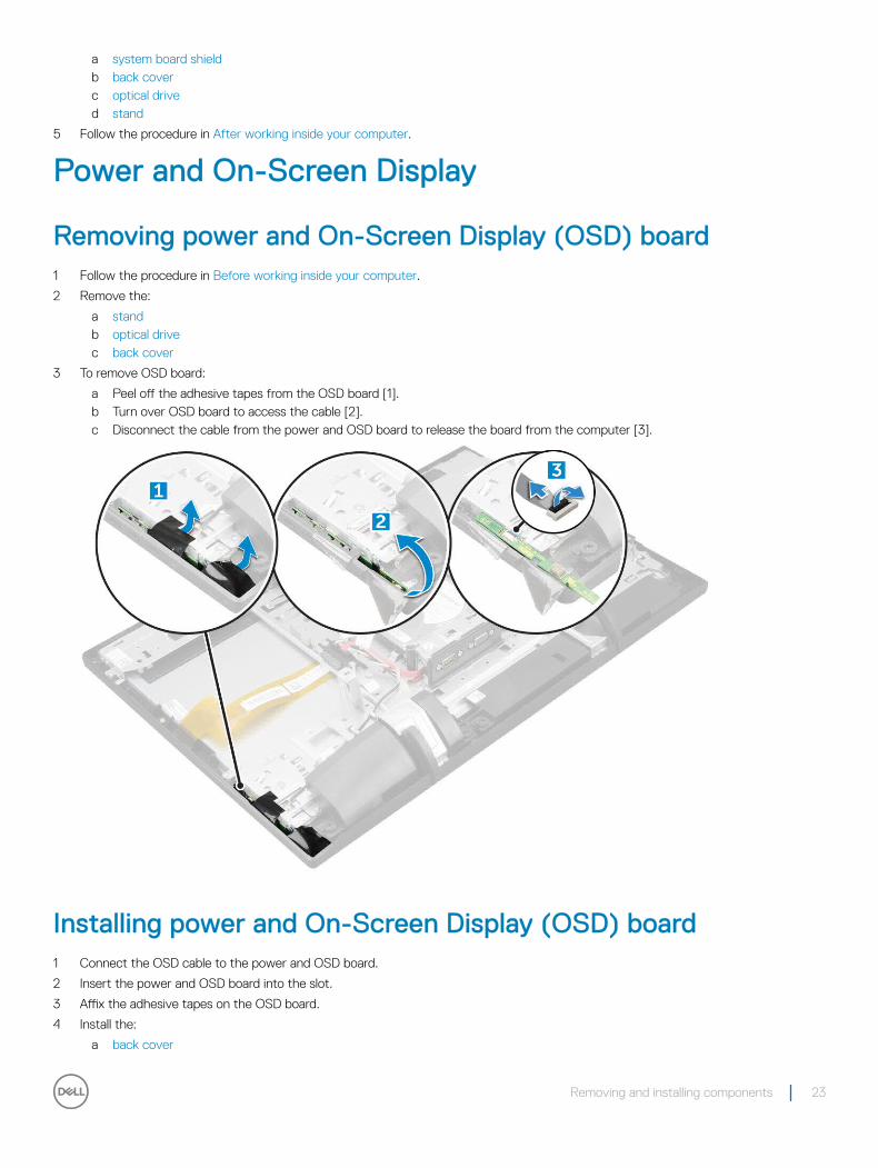
3 To remove OSD board:
a Peel off the adhesive tapes from the OSD board [1].b Turn over OSD board to access the cable [2].c Disconnect the cable from the power and OSD board to release the board from the computer [3].
Installing power and On-Screen Display (OSD) board1 Connect the OSD cable to the power and OSD board.
2 Insert the power and OSD board into the slot.
3 Affix the adhesive tapes on the OSD board.
4 Install the:
a back cover
Removing and installing components 23

b optical drivec stand
5 Follow the procedure in After working inside your computer.
Speaker
Removing speaker 1 Follow the procedure in Before working inside your computer.
2 Remove the:
a standb optical drivec back coverd system board shield
3 To remove speaker cover:
a Remove the M2x5 screws that secure the speaker cover to the computer [1].b Lift the speaker cover away from the computer [2].
4 To remove speaker:
a Disconnect the speaker cable from the system board [1].b Unthread the speaker cable from the retention clips [2].c Lift the speaker module away from the computer [3].
24 Removing and installing components
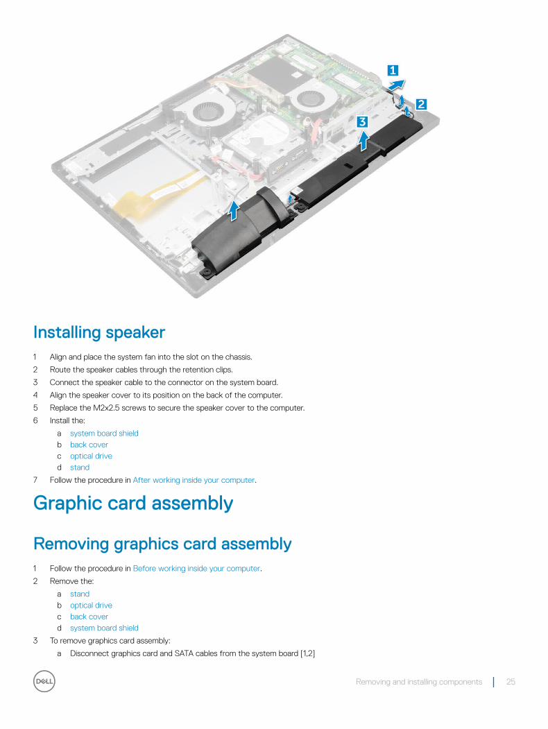
Installing speaker1 Align and place the system fan into the slot on the chassis.
2 Route the speaker cables through the retention clips.
3 Connect the speaker cable to the connector on the system board.
4 Align the speaker cover to its position on the back of the computer.
5 Replace the M2x2.5 screws to secure the speaker cover to the computer.
6 Install the:
a system board shieldb back coverc optical drived stand
7 Follow the procedure in After working inside your computer.
Graphic card assembly
Removing graphics card assembly1 Follow the procedure in Before working inside your computer.
2 Remove the:
a standb optical drivec back coverd system board shield
3 To remove graphics card assembly:
a Disconnect graphics card and SATA cables from the system board [1,2]
Removing and installing components 25

b Remove the M2x2.5 screws that secure graphics card assembly on the computer [3].c Lift the graphics card assembly away from the computer [4].
Installing graphics card assembly1 Align and place the graphics card assembly in the slot on the chassis.
2 Replace the M2x2.5 screws to secure the graphics card assembly on the computer.
3 Connect the graphics card and SATA ODD cables to the connector on the system board.
4 Install the:
a system board shieldb back coverc optical drived stand
5 Follow the procedure in After working inside your computer.
Processor
Removing processor1 Follow the procedure in Before working inside your computer.
2 Remove the:
a standb optical drivec back coverd system board shielde heat sink
3 To remove processor:
26 Removing and installing components

a Release the socket lever by pushing the lever down and out from under the tab on the processor shield [1].b Lift the lever upward, and lift the processor shield [2].
CAUTION: The processor socket pins are fragile and can be permanently damaged. Be careful not to bend the pins in the processor socket when removing the processor out of the socket.
c Lift the processor out of the socket [3].
CAUTION: After removing the processor, place it in an antistatic bag for reuse, return, or temporary storage. Do not touch the pins of the processor to avoid damage to the processor contacts. Touch only the side edges of the processor.
Installing processor1 Align the processor with the socket keys on the connector.
CAUTION: Do not use force to seat the processor. When the processor is positioned correctly, it engages easily into the socket
2 Align the pin-1 indicator of the processor with the triangle on the socket.
3 Place the processor on the socket such that the slots on the processor align with the socket keys.
4 Close the processor shield by sliding it under the retention screw.
5 Lower the socket lever and push it under the tab to lock it.
6 Install the:
a heat sinkb system board shieldc back coverd optical drivee stand
7 Follow the procedure in After working inside your computer.
System board
Removing system board1 Follow the procedure in Before working inside your computer.
2 Remove the:
a standb optical drivec back coverd hard drivee system board shieldf coin cell batteryg SSD card
Removing and installing components 27
h memory modulei WLAN cardj heat sinkk system fanl processor
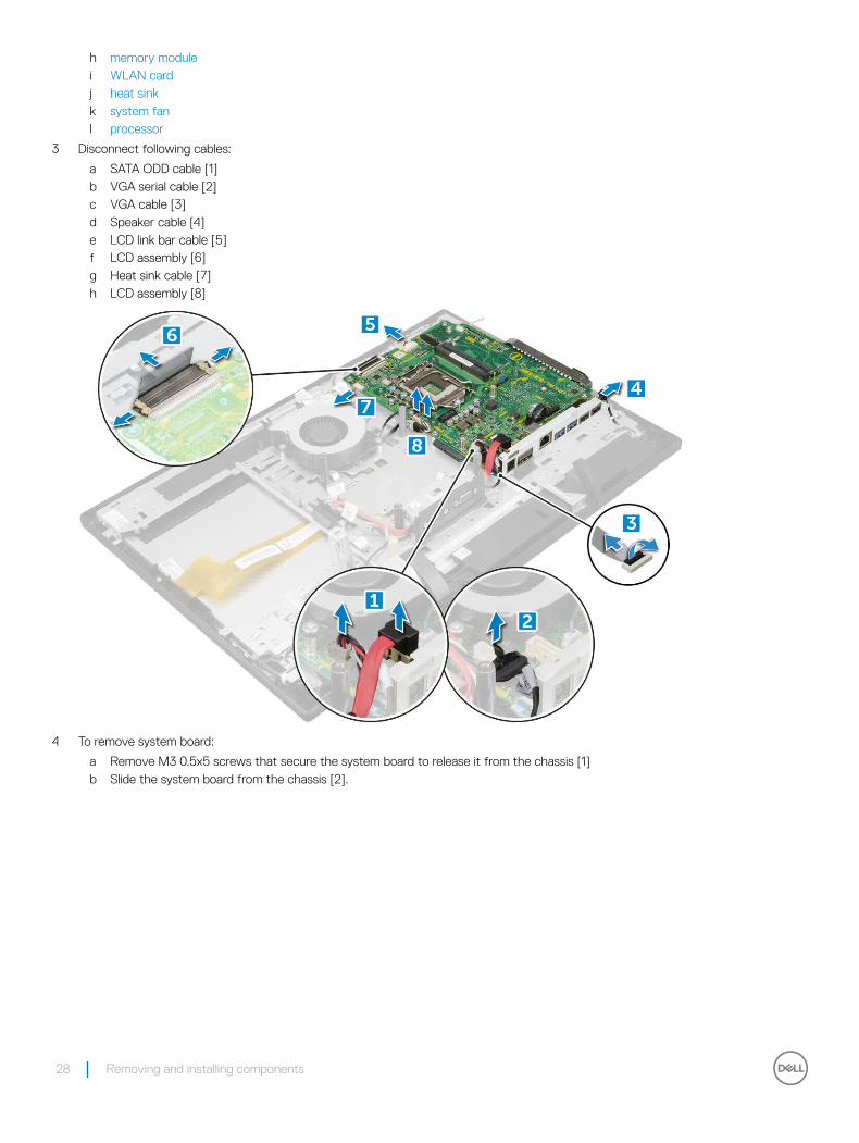
3 Disconnect following cables:
a SATA ODD cable [1]b VGA serial cable [2]c VGA cable [3]d Speaker cable [4]e LCD link bar cable [5]f LCD assembly [6]g Heat sink cable [7]h LCD assembly [8]
4 To remove system board:
a Remove M3 0.5x5 screws that secure the system board to release it from the chassis [1]b Slide the system board from the chassis [2].
28 Removing and installing components

5 Remove the system board.
Removing and installing components 29

Installing system board1 Place the system board on the chassis.
2 Replace the screws to secure the system board to the computer.
3 Connect the following cables to the system board:
a LCD assembly cableb Heat sink cablec LCD assembly cabled LCD link bar cablee Speaker cablef VGA serial cableg VGA cableh SATA ODD cable
4 Install the:
a processorb system fanc heat sinkd WLAN carde memory modulef SSD cardg coin cell batteryh system board shieldi hard drivej back coverk optical drivel stand
5 Follow the procedure in After working inside your computer.
Chassis frame
Removing chassis frame1 Follow the procedure in Before working inside your computer.
2 Remove the:
a standb optical drivec back coverd hard drivee system board shieldf cable holderg memory moduleh coin cell batteryi SSD cardj WLAN cardk heat sinkl processorm system fann OSD boardo speakerp graphics card assembly
30 Removing and installing components
q system board
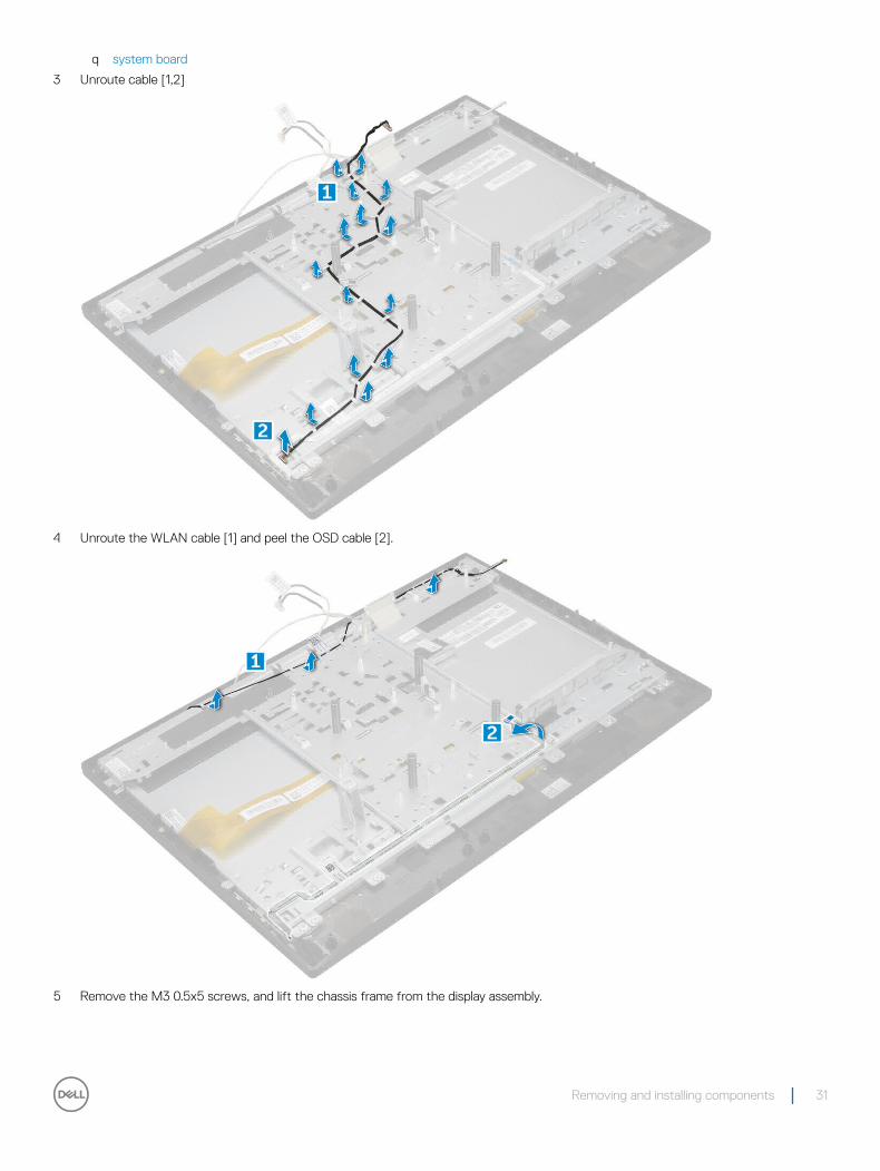
3 Unroute cable [1,2]
4 Unroute the WLAN cable [1] and peel the OSD cable [2].
5 Remove the M3 0.5x5 screws, and lift the chassis frame from the display assembly.
Removing and installing components 31

Installing chassis frame1 Align and place the chassis frame on the display assembly.
2 Replace the M3 0.5x5 screws to secure the chassis frame to the display assembly.
3 Route the cables to the chassis frame.
4 Install the:
a system boardb graphics card assemblyc speakerd OSD boarde system fanf processorg heat sinkh WLAN cardi SSD cardj coin cell batteryk memory modulel cable holderm system board shieldn hard driveo back coverp optical driveq stand
5 Follow the procedure in After working inside your computer.
32 Removing and installing components

Display assembly
Removing display assembly1 Follow the procedure in Before working inside your computer.
2 Remove the:
a standb optical drivec back coverd hard drivee system board shieldf cable holderg memory moduleh coin cell batteryi SSD cardj WLAN cardk heat sinkl processorm system fann OSD boardo speakerp graphics card assemblyq system boardr chassis frame
3 To disconnect the cable:
a Peel off the adhesive tapes that secure the display panel [1].b Disconnect the touch and eDP cable from the board [2].
4 To remove display assembly:
Removing and installing components 33
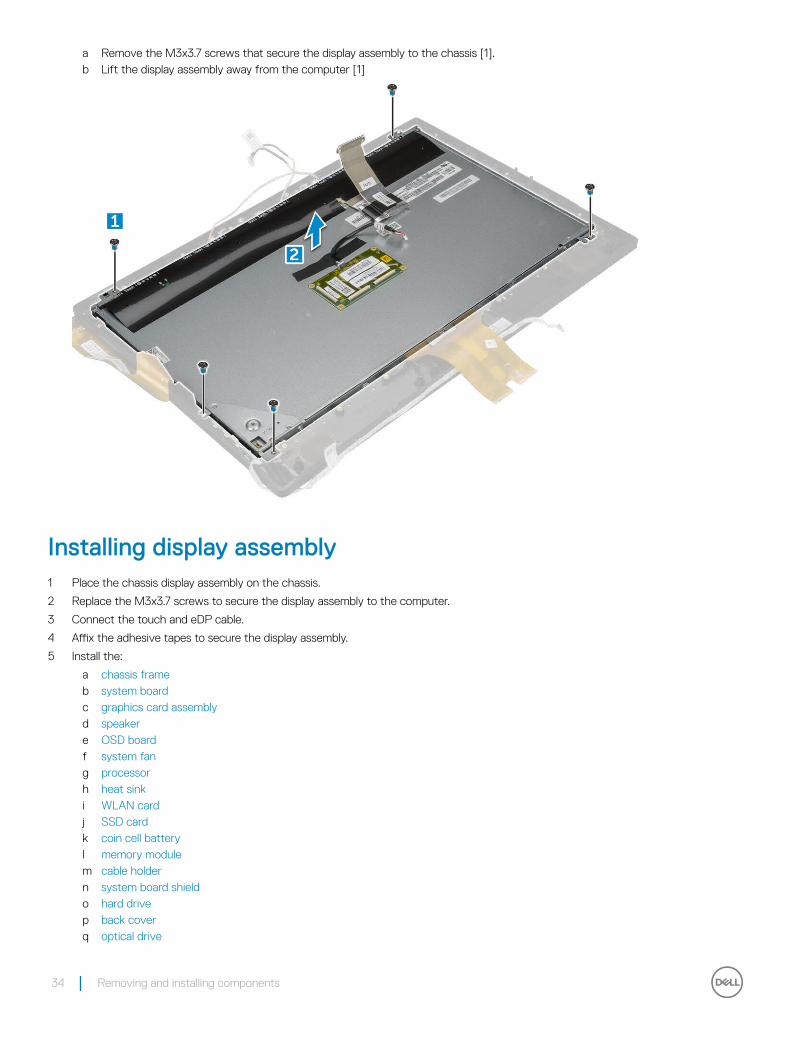
a Remove the M3x3.7 screws that secure the display assembly to the chassis [1].b Lift the display assembly away from the computer [1]
Installing display assembly1 Place the chassis display assembly on the chassis.
2 Replace the M3x3.7 screws to secure the display assembly to the computer.
3 Connect the touch and eDP cable.
4 Affix the adhesive tapes to secure the display assembly.
5 Install the:
a chassis frameb system boardc graphics card assemblyd speakere OSD boardf system fang processorh heat sinki WLAN cardj SSD cardk coin cell batteryl memory modulem cable holdern system board shieldo hard drivep back coverq optical drive
34 Removing and installing components

r stand
6 Follow the procedure in After working inside your computer.
Camera
Removing camera1 Follow the procedure in Before working inside your computer.
2 Remove the:a standb optical drivec back coverd hard drivee system board shieldf cable holderg memory moduleh coin cell batteryi SSD cardj WLAN cardk heat sinkl processorm system fann OSD boardo speakerp graphics card assemblyq system boardr chassis frames display assembly
3 To remove camera:a Remove the M3 0.5x5 screws that secure the camera [1].b Disconnect the camera cables [2].c Remove the camera module [3, 4].
Removing and installing components 35
Installing camera1 Align and place the camera module on the display frame on the computer.
2 Connect the camera cables.
3 Tighten the M3 0.5x5 screws to secure the camera to the computer.
4 Install the:
a display assemblyb chassis framec system boardd graphics card assemblye speakerf OSD boardg system fanh processori heat sinkj WLAN cardk SSD cardl coin cell batterym memory modulen cable holdero system board shieldp hard driveq back coverr optical drives stand
5 Follow the procedure in After working inside your computer.
36 Removing and installing components

Technology and components
This chapter details the technology and components available in the systems.
Topics:
• Processors
• Chipsets
• Display options
• Intel HD Graphics
• Hard drive options
• USB features
• Memory features
• Realtek HD audio drivers
ProcessorsOptiPlex 3050 AIO system is shipped with Intel 6th generation and 7th generation core processor technology.
• Intel 6th Generation Core i5-6500T QC/ 6 MB/ 4T/ 2.5 GHz, 35 W(Support for Windows 7/8.1/10/Linux)
• Intel 6th Generation Core i7-6700T QC, 8 MB, 8T, 2.8 GHz, 35 W (Support for Windows 7/8.1/10/Linux)
• Intel 7th Generation Core i5-7500T QC/ 6 MB/ 4T/ 2.7 GHz, 35 W (Support for Windows 10/Linux Only)
• Intel 7th Generation Intel Core i7-7700T QC/ 8 MB/ 8T/ 2.9 GHz, 35W (Support for Windows 10/Linux Only)
NOTE: The clock speed and performance varies depending on the workload and other variables. Total cache up to 8 MB cache depending on processor type.
Skylake processorIntel Skylake is the successor to the Intel® Broadwell processor. It is a microarchitecture redesign using an existing process technology and it is branded as Intel 6th Gen Core. Like Broadwell, Skylake is available in four variants with suffixes SKL-Y, SKL-H, SKL-U, and SKL-S.
The Skylake also includes Core i7, i5, i3, Pentium, and the Celeron processors.
Skylake specifications
Table 1. Skylake specifications
Processor number Clock Speed
Cache No. of cores/No. of threads
Power Memory type Graphics
Intel 6th Generation Core i5-6500T QC/ 6 MB/ 4T/ 2.5 GHz, 35 W
2.50 GHz 6 MB 4/4 35 W DDR4-2133 Intel HD graphics 530
3
Technology and components 37

Intel 6th Generation Core i7-6700T QC, 8 MB, 8T, 2.8 GHz, 35 W
2.80 GHz 8 MB 4/8 35 W DDR4-2133 Intel HD graphics 530
Kaby Lake — 7th Generation Intel Core processors
The 7th Gen Intel Core processor (Kaby Lake) family is the successor of 6th generation processors (Sky Lake). Its main features include:
• Intel 14 nm Manufacturing Process Technology
• Intel Turbo Boost Technology
• Intel Hyper Threading Technology
• Intel Built-in Visuals
• Intel HD graphics - exceptional videos, editing smallest details in the videos
• Intel Quick Sync Video - excellent video conferencing capability, quick video editing and authoring
• Intel Clear Video HD - visual quality and color fidelity enhancements for HD playback and immersing web browsing
• Integrated memory controller
• Intel Smart Cache
• Optional Intel vPro technology (on i5/i7) with Active Management Technology 11.6
• Intel Rapid Storage Technology
Kaby lake specifications
Table 2. Kaby lake specifications
Processor number Clock Speed
Cache No. of cores/No. of threads
Power Memory type Graphics
Intel 7th Generation Core i5-7500T, QC/ 6 MB/ 4T/ 2.7 GHz, 35 W
2.70 GHz 6 MB 4/4 35 W DDR4-2133 Mhz Intel HD Graphics 630
Intel 7th Generation Core i7-7700T, QC/ 8 MB/ 8T/ 2.9 GHz, 35W
2.90 GHz 8 MB 4/8 35 W DDR4-2400 Mhz Intel HD Graphics 630
Identifying processors in Windows 71 Click Start > Control Panel > Device Manager.
2 Select Processor.
Identifying processors in Windows 101 Tap Search the Web and Windows.
2 Type Device Manager.
3 Tap Processor.
38 Technology and components
Verifying the processor usage in Task Manager1 Right click on the desktop.
2 Select Start Task Manager.
The Windows Task Manager window is displayed.
3 Click the Performance tab in the Windows Task Manager window.
Verifying the processor usage in Resource Monitor1 Right click the desktop.
2 Select Start Task Manager.
The Windows Task Manager window is displayed.
3 Click the Performance tab in the Windows Task Manager window.
The processor performance details are displayed.
4 Click Open Resource Monitor.
ChipsetsAll Desktops communicate with the CPU through the chipset. This system is shipped with the Intel 100 Series chipset.
Identifying chipset in Device Manager on Windows 71 Click Start → Control Panel → Device Manager.
2 Expand System Devices and search for the chipset.
Identifying the chipset in Device Manager on Windows 10
1 Click All Settings on the Windows 10 Charms Bar.
2 From the Control Panel, select Device Manager.
3 Expand System Devices and search for the chipset.
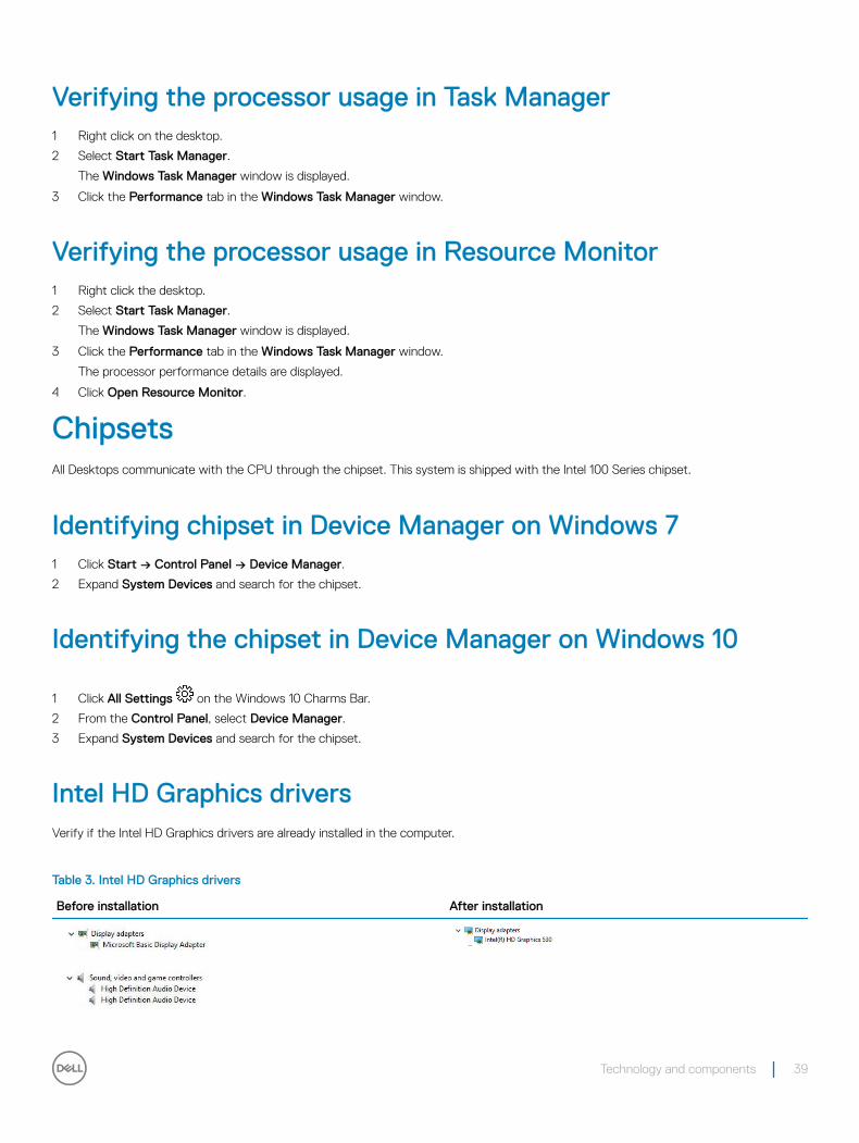
Intel HD Graphics driversVerify if the Intel HD Graphics drivers are already installed in the computer.
Table 3. Intel HD Graphics drivers
Before installation After installation
Technology and components 39
Downloading the chipset driver1 Turn on the computer.
2 Go to Dell.com/support.
3 Click Product Support, enter the Service Tag of your computer, and then click Submit.
NOTE: If you do not have the Service Tag, use the autodetect feature or manually browse for your computer model.
4 Click Drivers and Downloads.
5 Select the operating system installed in your computer.
6 Scroll down the page, expand Chipset, and select your chipset driver.
7 Click Download File to download the latest version of the chipset driver for your computer.
8 After the download is complete, navigate to the folder where you saved the driver file.
9 Double-click the chipset driver file icon and follow the instructions on the screen.
Downloading drivers1 Turn on the computer.
2 Go to Dell.com/support.
3 Click Product Support, enter the Service Tag of your computer, and then click Submit.
NOTE: If you do not have the Service Tag, use the auto detect feature or manually browse for your computer model.
4 Click Drivers and Downloads.
5 Select the operating system installed on your computer.
6 Scroll down the page and select the graphic driver to install.
7 Click Download File to download the graphic driver for your computer.
8 After the download is complete, navigate to the folder where you saved the graphic driver file.
9 Double-click the graphic driver file icon and follow the instructions on the screen.
Display options
Identifying the display adapter1 Start the Search Charm and select Settings.
2 Type Device Manager in the search box, and tap Device Manager from the left pane.
3 Expand Display adapters.
Changing the screen resolution1 Right click on the desktop and select Display Settings.
2 Tap or click Advanced display settings.
3 Select the required resolution from the drop-down list and tap Apply.
40 Technology and components
Adjusting brightness in Windows 7To enable or disable automatic screen brightness adjustment:
1 Click Start → Control Panel → Display.
2 Use the Adjust brightness slider to enable or disable automatic-brightness adjustment.
NOTE: You can also use the Brightness level slider to adjust the brightness manually.
Adjusting brightness in Windows 10To enable or disable automatic screen brightness adjustment:
1 Right-click All Settings → System → Display.
2 Use the Adjust my screen brightness automatically slider to enable or disable automatic-brightness adjustment.
NOTE: You can also use the Brightness level slider to adjust the brightness manually.
Connecting to external display devicesFollow these steps to connect your computer to an external display device:
1 Ensure that the projector is turned on and plug the projector cable into a video port on your computer.
2 Press the Windows logo+P key.
3 Select one of the following modes:
• PC screen only
• Duplicate
• Extend
• Second Screen only
Intel HD Graphics This computer is shipped with the Intel HD Graphics graphics chipset.
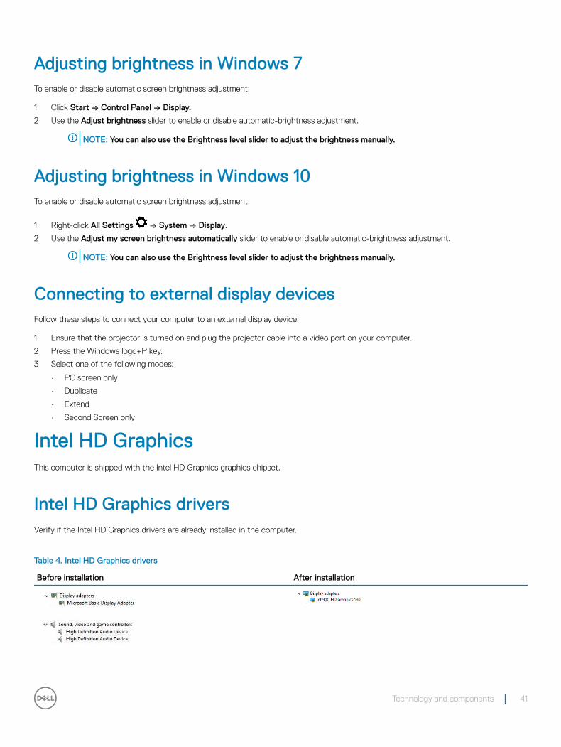
Intel HD Graphics driversVerify if the Intel HD Graphics drivers are already installed in the computer.
Table 4. Intel HD Graphics drivers
Before installation After installation
Technology and components 41

Hard drive optionsThis computer supports HDD and PCIe SSD.
Identifying the hard drive in Windows 71 Click Start > Control Panel > Device Manager.
The hard drive is listed under Disk drives.
2 Expand Disk drives.
Identifying the hard drive in Windows 10
1 Click All Settings on the Windows 10 Charms Bar.
2 Click Control Panel, select Device Manager, and expand Disk drives.
The hard drive is listed under Disk drives.
Entering BIOS setup1 Turn on or restart your laptop.
2 When the Dell logo appears, perform one of the following actions to enter the BIOS setup program:
• With keyboard — Tap F2 until the Entering BIOS setup message appears. To enter the Boot selection menu, tap F12.
Hard drive is listed under the System Information under the General group.
USB featuresThe Universal Serial Bus, or well known as USB was introduced to the PC world in 1996 which dramatically simplified the connection between host computer and peripheral devices such as mice and keyboards, external hard drive or optical devices, Bluetooth and many more peripheral devices in the market.
Let's take a quick look on the USB evolution referencing to the table below.
Table 5. USB evolution
Type Data Transfer Rate Category Introduction Year
USB 3.0/USB 3.1 Gen 1 5 Gbps Super Speed 2010
USB 2.0 480 Mbps High Speed 2000
USB 1.1 12 Mbps Full Speed 1998
USB 1.0 1.5 Mbps Low Speed 1996
USB 3.0/USB 3.1 Gen 1 (SuperSpeed USB)For years, the USB 2.0 has been firmly entrenched as the de facto interface standard in the PC world with about 6 billion devices sold, and yet the need for more speed grows by ever faster computing hardware and ever greater bandwidth demands. The USB 3.0/USB 3.1 Gen 1
42 Technology and components

finally has the answer to the consumers' demands with a theoretically 10 times faster than its predecessor. In a nutshell, USB 3.1 Gen 1 features are as follows:
• Higher transfer rates (up to 5 Gbps)
• Increased maximum bus power and increased device current draw to better accommodate power-hungry devices
• New power management features
• Full-duplex data transfers and support for new transfer types
• Backward USB 2.0 compatibility
• New connectors and cable
The topics below cover some of the most commonly asked questions regarding USB 3.0/USB 3.1 Gen 1.
SpeedCurrently, there are 3 speed modes defined by the latest USB 3.0/USB 3.1 Gen 1 specification. They are Super-Speed, Hi-Speed and Full-Speed. The new SuperSpeed mode has a transfer rate of 4.8Gbps. While the specification retains Hi-Speed, and Full-Speed USB mode, commonly known as USB 2.0 and 1.1 respectively, the slower modes still operate at 480Mbps and 12Mbps respectively and are kept to maintain backward compatibility.
USB 3.0/USB 3.1 Gen 1 achieves the much higher performance by the technical changes below:
• An additional physical bus that is added in parallel with the existing USB 2.0 bus (refer to the picture below).
• USB 2.0 previously had four wires (power, ground, and a pair for differential data); USB 3.0/USB 3.1 Gen 1 adds four more for two pairs of differential signals (receive and transmit) for a combined total of eight connections in the connectors and cabling.
• USB 3.0/USB 3.1 Gen 1 utilizes the bidirectional data interface, rather than USB 2.0's half-duplex arrangement. This gives a 10-fold increase in theoretical bandwidth.
With today's ever increasing demands placed on data transfers with high-definition video content, terabyte storage devices, high megapixel count digital cameras etc., USB 2.0 may not be fast enough. Furthermore, no USB 2.0 connection could ever come close to the 480Mbps theoretical maximum throughput, making data transfer at around 320Mbps (40MB/s) — the actual real-world maximum. Similarly, USB 3.0/USB 3.1 Gen 1 connections will never achieve 4.8Gbps. We will likely see a real-world maximum rate of 400MB/s with overheads. At this speed, USB 3.0/USB 3.1 Gen 1 is a 10x improvement over USB 2.0.
Technology and components 43

ApplicationsUSB 3.0/USB 3.1 Gen 1 opens up the laneways and provides more headroom for devices to deliver a better overall experience. Where USB video was barely tolerable previously (both from a maximum resolution, latency, and video compression perspective), it's easy to imagine that with 5-10 times the bandwidth available, USB video solutions should work that much better. Single-link DVI requires almost 2Gbps throughput. Where 480Mbps was limiting, 5Gbps is more than promising. With its promised 4.8Gbps speed, the standard will find its way into some products that previously weren't USB territory, like external RAID storage systems.
Listed below are some of the available SuperSpeed USB 3.0/USB 3.1 Gen 1 products:
• External Desktop USB 3.0/USB 3.1 Gen 1 Hard Drives
• Portable USB 3.0/USB 3.1 Gen 1 Hard Drives
• USB 3.0/USB 3.1 Gen 1 Drive Docks & Adapters
• USB 3.0/USB 3.1 Gen 1 Flash Drives & Readers
• USB 3.0/USB 3.1 Gen 1 Solid-state Drives
• USB 3.0/USB 3.1 Gen 1 RAIDs
• Optical Media Drives
• Multimedia Devices
• Networking
• USB 3.0/USB 3.1 Gen 1 Adapter Cards & Hubs
CompatibilityThe good news is that USB 3.0/USB 3.1 Gen 1 has been carefully planned from the start to peacefully co-exist with USB 2.0. First of all, while USB 3.0/USB 3.1 Gen 1 specifies new physical connections and thus new cables to take advantage of the higher speed capability of the new protocol, the connector itself remains the same rectangular shape with the four USB 2.0 contacts in the exact same location as before. Five new connections to carry receive and transmitted data independently are present on USB 3.0/USB 3.1 Gen 1 cables and only come into contact when connected to a proper SuperSpeed USB connection.
Windows 8/10 will be bringing native support for USB 3.1 Gen 1 controllers. This is in contrast to previous versions of Windows, which continue to require separate drivers for USB 3.0/USB 3.1 Gen 1 controllers.
Microsoft announced that Windows 7 would have USB 3.1 Gen 1 support, perhaps not on its immediate release, but in a subsequent Service Pack or update. It is not out of the question to think that following a successful release of USB 3.0/USB 3.1 Gen 1 support in Windows 7, SuperSpeed support would trickle down to Vista. Microsoft has confirmed this by stating that most of their partners share the opinion that Vista should also support USB 3.0/USB 3.1 Gen 1.
Super-Speed support for Windows XP is unknown at this point. Given that XP is a seven-year-old operating system, the likelihood of this happening is remote.
Memory featuresIn this computer, the memory (RAM) is a part of the system board.
• This computer supports 2133 MHz DDR4 for Intel 6th generation processor.
• This computer supports 2400 MHz DDR4 for Intel 7th generation processor.
44 Technology and components

Verifying system memory in Windows 10 and Windows 7
Windows 10
1 Click the Windows button and select All Settings > System.
2 Under System, click About.
Windows 7
• Click Start → Control Panel → System.
Verifying system memory in setup1 Turn on or restart your computer..
2 Perform one of the following actions after the Dell logo is displayed:
• With keyboard — Tap F2 until the Entering BIOS setup message appears. To enter the Boot selection menu, tap F12.
3 On the left pane, select Settings > General > System Information,
The memory information is displayed on the right pane.
DDR4DDR4 (double data rate fourth generation) memory is a higher-speed successor to the DDR2 and DDR3 technologies and allows up to 512 GB in capacity, compared to the DDR3's maximum capacity of 128 GB per DIMM. DDR4 synchronous dynamic random-access memory is keyed differently from both SDRAM and DDR to prevent the user from installing the wrong type of memory into the system.
DDR4 needs 20 percent less or just 1.2 volts, compared to DDR3 which requires 1.5 volts of electrical power to operate. DDR4 also supports a new, deep power-down mode that allows the host device to go into standby without needing to refresh its memory. Deep power-down mode is expected to reduce standby power consumption by 40 to 50 percent.
DDR4 Details
There are subtle differences between DDR3 and DDR4 memory modules, as listed below.
Key notch difference
The key notch on a DDR4 module is in a different location from the key notch on a DDR3 module. Both notches are on the insertion edge, but the notch location on the DDR4 is slightly different, to prevent the module from being installed into an incompatible board or platform.
Technology and components 45

Figure 1. Notch difference
Increased thickness
DDR4 modules are slightly thicker than DDR3, to accommodate more signal layers.
Figure 2. Thickness difference
Curved edge
DDR4 modules feature a curved edge to help with insertion and alleviate stress on the PCB during memory installation.
Figure 3. Curved edge
Testing memory using ePSA1 Turn on or restart your computer.
2 Perform one of the following actions after the Dell logo is displayed:
• With keyboard — Press F2.
The PreBoot System Assessment (PSA) starts on your computer.
NOTE: If you wait too long and the operating system logo appears, continue to wait until you see the desktop. Turn off the computer and try again.
Realtek HD audio driversVerify if the Realtek audio drivers are already installed in the computer.
46 Technology and components
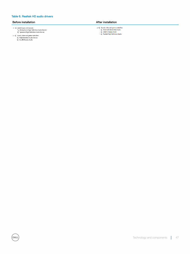
Table 6. Realtek HD audio drivers
Before installation After installation
Technology and components 47
System setupSystem Setup enables you to manage your computer hardware and specify BIOS level options. From the System Setup, you can:
• Change the NVRAM settings after you add or remove hardware
• View the system hardware configuration
• Enable or disable integrated devices
• Set performance and power management thresholds
• Manage your computer security
BIOS Overview
Boot menu
Press <F12> when the Dell™ logo appears to initiate a one-time boot menu with a list of the valid boot devices for the system. Diagnostics and BIOS Setup options are also included in this menu. The devices listed on the boot menu depend on the bootable devices in the system. This menu is useful when you are attempting to boot to a particular device or to bring up the diagnostics for the system. Using the boot menu does not make any changes to the boot order stored in the BIOS.
The options are:
• Legacy Boot:
• Internal HDD
• Onboard NIC
• UEFI Boot:
• Windows Boot Manager
• Other Options:
• BIOS Setup
• BIOS Flash Update
• Diagnostics
• Change Boot Mode Settings
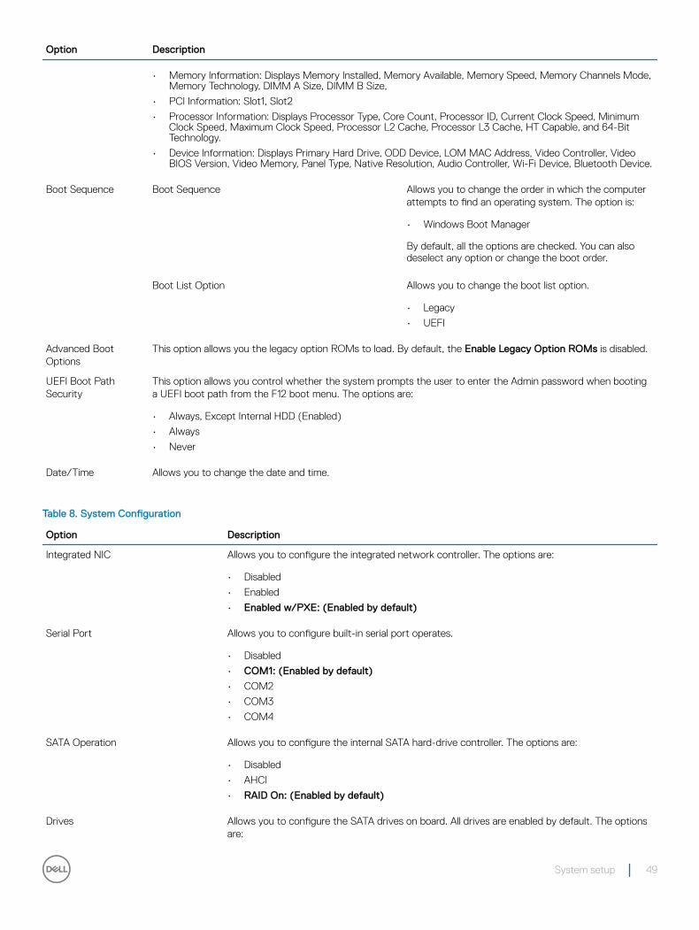
System setup optionsNOTE: Depending on the computer and its installed devices, the items listed in this section may or may not appear.
Table 7. General tab
Option Description
System Information This section lists the primary hardware features of your computer.
• System Information: Displays BIOS Version, Service Tag, Asset Tag, Ownership Tag, Ownership Date, Manufacture Date, and the Express Service Code.
4
48 System setup
Option Description
• Memory Information: Displays Memory Installed, Memory Available, Memory Speed, Memory Channels Mode, Memory Technology, DIMM A Size, DIMM B Size,
• PCI Information: Slot1, Slot2
• Processor Information: Displays Processor Type, Core Count, Processor ID, Current Clock Speed, Minimum Clock Speed, Maximum Clock Speed, Processor L2 Cache, Processor L3 Cache, HT Capable, and 64-Bit Technology.
• Device Information: Displays Primary Hard Drive, ODD Device, LOM MAC Address, Video Controller, Video BIOS Version, Video Memory, Panel Type, Native Resolution, Audio Controller, Wi-Fi Device, Bluetooth Device.
Boot Sequence Boot Sequence Allows you to change the order in which the computer attempts to find an operating system. The option is:
• Windows Boot Manager
By default, all the options are checked. You can also deselect any option or change the boot order.
Boot List Option Allows you to change the boot list option.
• Legacy
• UEFI
Advanced Boot Options
This option allows you the legacy option ROMs to load. By default, the Enable Legacy Option ROMs is disabled.
UEFI Boot Path Security
This option allows you control whether the system prompts the user to enter the Admin password when booting a UEFI boot path from the F12 boot menu. The options are:
• Always, Except Internal HDD (Enabled)
• Always
• Never
Date/Time Allows you to change the date and time.
Table 8. System Configuration
Option Description
Integrated NIC Allows you to configure the integrated network controller. The options are:
• Disabled
• Enabled
• Enabled w/PXE: (Enabled by default)
Serial Port Allows you to configure built-in serial port operates.
• Disabled
• COM1: (Enabled by default)
• COM2
• COM3
• COM4
SATA Operation Allows you to configure the internal SATA hard-drive controller. The options are:
• Disabled
• AHCI
• RAID On: (Enabled by default)
Drives Allows you to configure the SATA drives on board. All drives are enabled by default. The options are:
System setup 49

Option Description
• SATA-0: (Enabled by default)
• SATA-1: (Enabled by default)
• M.2 PCIe SSD-0: (Enabled by default)
SMART Reporting This field controls whether hard drive errors for integrated drives are reported during system startup. This technology is part of the SMART (Self-Monitoring Analysis and Reporting Technology) specification.
• Enable SMART Reporting (Disabled by default)
USB Configuration This field configures the integrated USB controller. If Boot Support is enabled, the system is allowed to boot any type of USB Mass Storage Devices (HDD, memory key, floppy).
If USB port is enabled, device attached to this port is enabled and available for OS.
If USB port is disabled, the OS cannot see any device attached to this port.
• Enable Boot Support
• Enable Side USB Ports
• Enable Rear USB Ports
NOTE: USB keyboard and mouse always work in the BIOS setup irrespective of these settings.
Rear USB Configuration This field enables or disables the rear USB configuration
• Left*
• Center Right
• Center Left*
• Right
NOTE: *Left port denotes a USB 3.1 Gen 1 capable port.
Side USB Configuration This field enables or disables the side USB configuration
• Side Port 1 (Top)*
• Side Port 2 (Bottom)*
NOTE: *Side Port 1 (Top) port denotes a USB 3.1 Gen 1 capable port.
USB PowerShare Allows you to configures the USB PowerShare feature behavior.
• Enable USB PowerShare (Disabled)
Audio This field enables or disables the integrated audio controller. By default, the Enable Audio option is selected. The options are:
• Enable Microphone
• Enable Internal Speaker
OSB Button Management This field allows the user to disable the OSB (On-Screen Display) buttons on their AIO.
• Disabled OSD Buttons (Disabled)
Touchscreen This field controls whether the touchscreen is enabled or disabled.
• Touchscreen (Enabled)
Miscellaneous Devices Allows you to enable or disable the following devices:
• Enable Camera (Enabled)
• Enabled Secure Digital (SD) Card (Enabled)
50 System setup
Option Description
• Secure Digital (SD) card Boot
• Secure Digital (SD) card Read-Only Mode
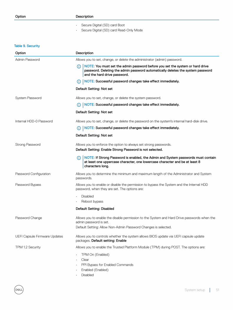
Table 9. Security
Option Description
Admin Password Allows you to set, change, or delete the administrator (admin) password.
NOTE: You must set the admin password before you set the system or hard drive password. Deleting the admin password automatically deletes the system password and the hard drive password.
NOTE: Successful password changes take effect immediately.
Default Setting: Not set
System Password Allows you to set, change, or delete the system password.
NOTE: Successful password changes take effect immediately.
Default Setting: Not set
Internal HDD-0 Password Allows you to set, change, or delete the password on the system's internal hard-disk drive.
NOTE: Successful password changes take effect immediately.
Default Setting: Not set
Strong Password Allows you to enforce the option to always set strong passwords.
Default Setting: Enable Strong Password is not selected.
NOTE: If Strong Password is enabled, the Admin and System passwords must contain at least one uppercase character, one lowercase character and be at least 8 characters long.
Password Configuration Allows you to determine the minimum and maximum length of the Administrator and System passwords.
Password Bypass Allows you to enable or disable the permission to bypass the System and the Internal HDD password, when they are set. The options are:
• Disabled
• Reboot bypass
Default Setting: Disabled
Password Change Allows you to enable the disable permission to the System and Hard Drive passwords when the admin password is set.
Default Setting: Allow Non-Admin Password Changes is selected.
UEFI Capsule Firmware Updates Allows you to controls whether the system allows BIOS update via UEFI capsule update packages. Default setting: Enable
TPM 1.2 Security Allows you to enable the Trusted Platform Module (TPM) during POST. The options are:
• TPM On (Enabled)
• Clear
• PPI Bypass for Enabled Commands
• Enabled (Enabled)
• Disabled
System setup 51
Option Description
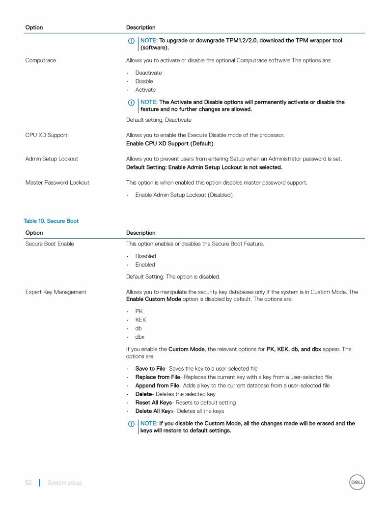
NOTE: To upgrade or downgrade TPM1.2/2.0, download the TPM wrapper tool (software).
Computrace Allows you to activate or disable the optional Computrace software The options are:
• Deactivate
• Disable
• Activate
NOTE: The Activate and Disable options will permanently activate or disable the feature and no further changes are allowed.
Default setting: Deactivate
CPU XD Support Allows you to enable the Execute Disable mode of the processor.
Enable CPU XD Support (Default)
Admin Setup Lockout Allows you to prevent users from entering Setup when an Administrator password is set.
Default Setting: Enable Admin Setup Lockout is not selected.
Master Password Lockout This option is when enabled this option disables master password support.
• Enable Admin Setup Lockout (Disabled)
Table 10. Secure Boot
Option Description
Secure Boot Enable This option enables or disables the Secure Boot Feature.
• Disabled
• Enabled
Default Setting: The option is disabled.
Expert Key Management Allows you to manipulate the security key databases only if the system is in Custom Mode. The Enable Custom Mode option is disabled by default. The options are:
• PK
• KEK
• db
• dbx
If you enable the Custom Mode, the relevant options for PK, KEK, db, and dbx appear. The options are:
• Save to File- Saves the key to a user-selected file
• Replace from File- Replaces the current key with a key from a user-selected file
• Append from File- Adds a key to the current database from a user-selected file
• Delete- Deletes the selected key
• Reset All Keys- Resets to default setting
• Delete All Keys- Deletes all the keys
NOTE: If you disable the Custom Mode, all the changes made will be erased and the keys will restore to default settings.
52 System setup

Table 11. Intel Software Guard Extensions screen options
Option Description
Intel SGX Enable This field specifies you to provide a secured environment for running code/storing sensitive information in the context of the main OS. The options are:
• Disabled
• Enabled
• Software Controlled (Enabled)
Enclave Memory Size This option sets SGX Enclave Reserve Memory Size. The options are:
• 32 MB
• 64 MB
• 128 MB
Table 12. Performance
Option Description
Multi Core Support This field specifies whether the process has one or all cores enabled. The performance of some applications improve with the additional cores. This option is enabled by default. Allows you to enable or disable multi-core support for the processor. The installed processor supports two cores. If you enable Multi Core Support, two cores are enabled. If you disable Multi Core Support, one core will be enabled.
• All (Enabled)
• 1
• 2
• 3
Intel SpeedStep Allows you to enable or disable the Intel SpeedStep feature.
• Enable Intel SpeedStep
Default Setting: The option is enabled.
C States Control Allows you to enable or disable the additional processor sleep states.
• C states
Default Setting: The option is enabled.
Limited CPUID Value This field limits the maximum value the processor standard CPUID function will support.
• Enable CPUID Limit
Intel TurboBoost Allows you to enable or disable the Intel TurboBoost mode of the processor.
• Enable Intel TurboBoost
Default Setting: The option is enabled.
HyperThread control This option enables or disables HyperThreading in the processor.
• Disabled
• Enabled (Default)
System setup 53

Table 13. Power Management
Option Description
AC Behavior Allows you to enable or disable the computer from turning on automatically when an AC adapter is connected.
• Power Off (Default)
• Power On
• Last Power State
Auto On Time Allows you to set the time at which the computer must turn on automatically. The options are:
• Disabled (Default)
• Every Day
• Weekdays
• Select Days
Deep Sleep Control Allows you to aggressive the system is at conserving power while Shut down (S5) or in Hybernate (S4) mode.
• Disabled (Default)
• Enabled in S5 only
• Enabled in S4 and S5
Fan Control Override This field determines the speed of the system fan.
• Fan Control Override (Disabled)
USB Wake Support Allows you to enable USB devices to wake the system from Standby.
NOTE: This feature is only functional when the AC power adapter is connected. If the AC power adapter is removed during Standby, the system setup will remove power from all of the USB ports to conserve battery power.
• Enable USB Wake Support
Default Setting: The option is disabled.
Wake on LAN/WLAN Allows you to enable or disable the feature that powers on the computer from the Off state when triggered by a LAN signal.
• Disabled: This option is enabled by default
• LAN Only
• WLAN Only
• LAN or WLAN
• LAN with PXE Boot
Block Sleep Allows you to block entering to sleep (S3 state) in OS environment.
Default Setting: The option is disabled.
Intel Ready Mode Allows you to replace sleep S3 to put your PC in an always aware state that allows the user to interact with it even while the PC is asleep
• Enable Intel Ready Mode: The option is disabled.
54 System setup

Table 14. POST Behavior
Option Description
Adapter Warnings Allows you to enable or disable the system setup (BIOS) warning messages when you use certain power adapters.
• Default Setting: Enable Adapter Warnings
Numlock LED This option specifies whether the NumLock LED should be on when the system boots.
• Enable Numlock LED: The option is enabled.
Keyboard Errors This option specifies whether the keyboard related errors are reported when it boots.
• Enables Keyboard Error Detection: The option is disabled.
Fastboot Allows you to speed up the boot process by bypassing some of the compatibility steps. The options are:
• Minimal(default)
• Thorough
• Auto
Extended BIOS POST Time Allows you to create an additional preboot delay. The options are:
• 0 seconds. This option is enabled by default.
• 5 seconds
• 10 seconds
Full Screen Logo This option displays full screen logo if your image match screen resolution.
• Enable Full Screen Logo (Disabled)
Warnings and Errors This option is caused when warnings and errors are detected.
• Prompt on Warnings and Error (Enabled)
• Continue on Warnings
• Continue on Warnings and Errors
Table 15. Virtualization Support
Option Description
Virtualization Allows you to enable or disable the Intel Virtualization Technology.
• Enable Intel Virtualization Technology (default)
VT for Direct I/O Enables or disables the Virtual Machine Monitor (VMM) from utilizing the additional hardware capabilities provided by Intel® Virtualization technology for direct I/O.
Enable VT for Direct I/O — enabled by default.
Table 16. Wireless
Option Description
Wireless Device Enable This field allows enabling/disabling of internal wireless devices.
• WLAN/WiGig
System setup 55
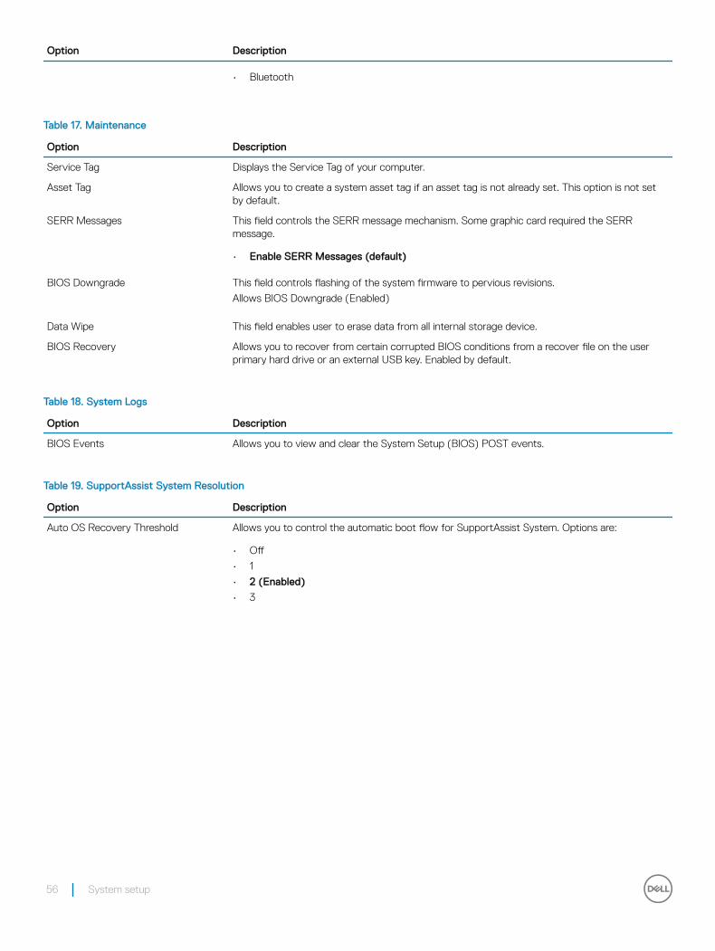
Option Description
• Bluetooth
Table 17. Maintenance
Option Description
Service Tag Displays the Service Tag of your computer.
Asset Tag Allows you to create a system asset tag if an asset tag is not already set. This option is not set by default.
SERR Messages This field controls the SERR message mechanism. Some graphic card required the SERR message.
• Enable SERR Messages (default)
BIOS Downgrade This field controls flashing of the system firmware to pervious revisions.
Allows BIOS Downgrade (Enabled)
Data Wipe This field enables user to erase data from all internal storage device.
BIOS Recovery Allows you to recover from certain corrupted BIOS conditions from a recover file on the user primary hard drive or an external USB key. Enabled by default.
Table 18. System Logs
Option Description
BIOS Events Allows you to view and clear the System Setup (BIOS) POST events.
Table 19. SupportAssist System Resolution
Option Description
Auto OS Recovery Threshold Allows you to control the automatic boot flow for SupportAssist System. Options are:
• Off
• 1
• 2 (Enabled)
• 3
56 System setup
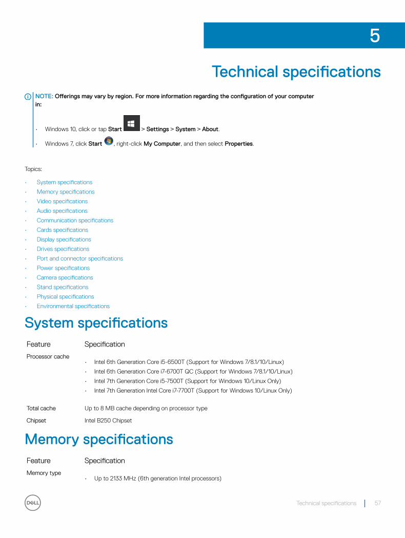
Technical specificationsNOTE: Offerings may vary by region. For more information regarding the configuration of your computer in:
• Windows 10, click or tap Start > Settings > System > About.
• Windows 7, click Start , right-click My Computer, and then select Properties.
Topics:
• System specifications
• Memory specifications
• Video specifications
• Audio specifications
• Communication specifications
• Cards specifications
• Display specifications
• Drives specifications
• Port and connector specifications
• Power specifications
• Camera specifications
• Stand specifications
• Physical specifications
• Environmental specifications
System specificationsFeature Specification
Processor cache• Intel 6th Generation Core i5-6500T (Support for Windows 7/8.1/10/Linux)
• Intel 6th Generation Core i7-6700T QC (Support for Windows 7/8.1/10/Linux)
• Intel 7th Generation Core i5-7500T (Support for Windows 10/Linux Only)
• Intel 7th Generation Intel Core i7-7700T (Support for Windows 10/Linux Only)
Total cache Up to 8 MB cache depending on processor type
Chipset Intel B250 Chipset
Memory specificationsFeature Specification
Memory type• Up to 2133 MHz (6th generation Intel processors)
5
Technical specifications 57
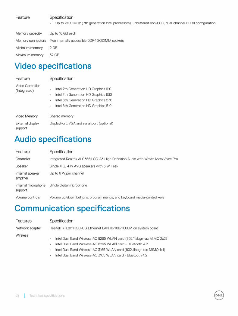
Feature Specification• Up to 2400 MHz (7th generation Intel processors), unbuffered non-ECC, dual‑channel DDR4 configuration
Memory capacity Up to 16 GB each
Memory connectors Two internally accessible DDR4 SODIMM sockets
Minimum memory 2 GB
Maximum memory 32 GB
Video specificationsFeature Specification
Video Controller (Integrated) • Intel 7th Generation HD Graphics 610
• Intel 7th Generation HD Graphics 630
• Intel 6th Generation HD Graphics 530
• Intel 6th Generation HD Graphics 510
Video Memory Shared memory
External display support
DisplayPort, VGA and serial port (optional)
Audio specificationsFeature Specification
Controller Integrated Realtek ALC3661-CG-A3 High Definition Audio with Waves MaxxVoice Pro
Speaker Single 4 Ω, 4 W AVG speakers with 5 W Peak
Internal speaker amplifier
Up to 6 W per channel
Internal microphone support
Single digital microphone
Volume controls Volume up/down buttons, program menus, and keyboard media-control keys
Communication specificationsFeatures Specification
Network adapter Realtek RTL8111HSD-CG Ethernet LAN 10/100/1000M on system board
Wireless• Intel Dual Band Wireless-AC 8265 WLAN card (802.11abgn+ac MIMO 2x2)
• Intel Dual Band Wireless-AC 8265 WLAN card - Bluetooth 4.2
• Intel Dual Band Wireless-AC 3165 WLAN card (802.11abgn+ac MIMO 1x1)
• Intel Dual Band Wireless-AC 3165 WLAN card - Bluetooth 4.2
58 Technical specifications

Cards specificationsFeature Specification
M.2 One
Display specificationsFeature Specification
Type 19.5 inches, HD+ WLED
Maximum resolution 1600 x 900
Refresh rate 60 Hz
Brightness Brightness up/down buttons
Operating angle 85 degrees horizontal/ 75 degrees vertical
Pixel pitch• 271.2 mm x 262.6 mm (touch)
• 270 mm x 270 mm (non-touch)
Height 452 mm (17.75 inches)
Width 263 mm (10.35 inches)
Drives specificationsFeature Specification
Hard drive One 2.5 inches SATA drive
Optical drive (optional)
DVD+/-RW SATA
Port and connector specificationsFeature Specification
Audio One Universal audio jack
Network adapter One RJ-45 connector
USB 2.0• Two USB 2.0 ports (rear)
• Three USB ports (internal)
USB 3.1 Gen 1• Two USB 3.1 Gen 1 ports (side)
• Two USB 3.1 Gen 1 ports (rear)
Video One DisplayPort, VGA and serial port (optional)
Media card reader One 4-in-1 slot
Technical specifications 59
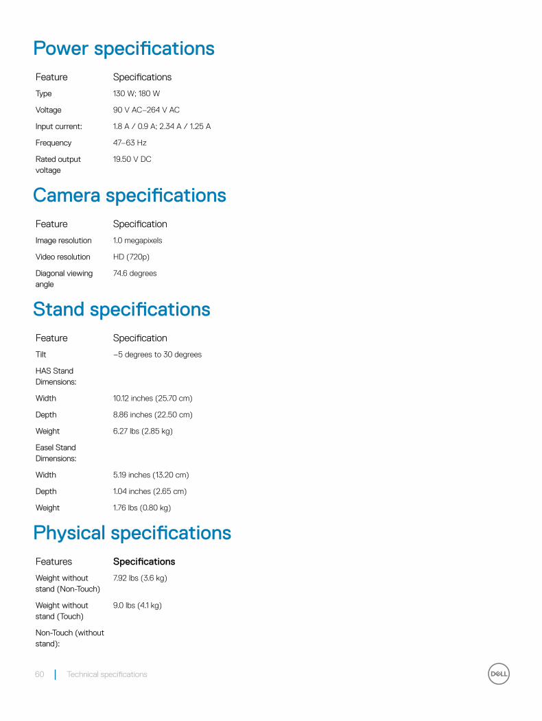
Power specificationsFeature Specifications
Type 130 W; 180 W
Voltage 90 V AC–264 V AC
Input current: 1.8 A / 0.9 A; 2.34 A / 1.25 A
Frequency 47–63 Hz
Rated output voltage
19.50 V DC
Camera specificationsFeature Specification
Image resolution 1.0 megapixels
Video resolution HD (720p)
Diagonal viewing angle
74.6 degrees
Stand specificationsFeature Specification
Tilt –5 degrees to 30 degrees
HAS Stand Dimensions:
Width 10.12 inches (25.70 cm)
Depth 8.86 inches (22.50 cm)
Weight 6.27 lbs (2.85 kg)
Easel Stand Dimensions:
Width 5.19 inches (13.20 cm)
Depth 1.04 inches (2.65 cm)
Weight 1.76 lbs (0.80 kg)
Physical specificationsFeatures Specifications
Weight without stand (Non-Touch)
7.92 lbs (3.6 kg)
Weight without stand (Touch)
9.0 lbs (4.1 kg)
Non-Touch (without stand):
60 Technical specifications

Features Specifications
Height 12.94 inches (32.87 cm)
Width 19.0 inches (48.25 cm)
Depth 2.38 inches (5.89 cm)
Touch (without stand):
Height 12.94 inches (32.87 cm)
Width 19.00 inches (48.25 cm)
Depth 2.32 inches (5.80 cm)
Environmental specificationsTemperature Specifications
Operating 0°C to 35°C (32°F to 95°F)
Storage –40°C to 65°C (–40°F to 149°F)
Relative humidity (maximum)
Specifications
Operating 20% to 80% (non condensing)
Storage 20% to 80% (non condensing)
Maximum vibration
Specifications
Operating 0.26 GRMS at 5 Hz to 350 Hz
Storage 1.37 GRMS at 5 Hz to 200 Hz
Maximum shock Specifications
Operating 40 G
Storage 105 G
Altitude (maximum)
Specifications
Operating 0 m to 5000 m (0 ft to 16,404 ft)
Non-operating 0 m to 5000 m (0 ft to 16,404 ft)
Airborne contaminant level
G2 or lower as defined by ANSI/ISA-S71.04-1985
Technical specifications 61

Troubleshooting
Enhanced Pre-Boot System Assessment (ePSA) diagnosticsThe ePSA diagnostics (also known as system diagnostics) performs a complete check of your hardware. The ePSA is embedded with the BIOS and is launched by the BIOS internally. The embedded system diagnostics provides a set of options for particular devices or device groups allowing you to:
• Run tests automatically or in an interactive mode
• Repeat tests
• Display or save test results
• Run thorough tests to introduce additional test options to provide extra information about the failed device(s)
• View status messages that inform you if tests are completed successfully
• View error messages that inform you of problems encountered during testing
CAUTION: Use the system diagnostics to test only your computer. Using this program with other computers may cause invalid results or error messages.
NOTE: Some tests for specific devices require user interaction. Always ensure that you are present at the computer terminal when the diagnostic tests are performed.
NOTE: Regular ePSA’s run for about 5 to 10 minutes, however, the extended test takes about three and half hours with only 8GB of ram in the system.
Running the ePSA diagnostics1 Power-on the computer.
2 As the computer boots, press the F12 key as the Dell logo appears.
3 On the boot menu screen, select the Diagnostics option.
The Enhanced Pre-boot System Assessment window is displayed, listing all devices detected in the computer. The diagnostics starts running the tests on all the detected devices.
4 To run a diagnostic test on a specific device, press Esc and click Yes to stop the diagnostic test.
5 Select the device from the left pane and click Run Tests.
6 If there are any issues, error codes are displayed.
Note the error code and contact Dell.
LCD built in self test (BIST)All-in-One (AIO) systems supports LCD BIST similar to any other Dell systems that have BIST test implemented. It allows the user to isolate the LCD during troubleshooting to determine which sub-system is at fault. The main difference is the lack of an integrated keyboard scan controller in the AIO. When BIST is initiated, an internal generated pattern from the LCD will be emitted for user's observation. This pattern will go by sequence through this pattern. Black-White-Red-Green-Blue or a White-Black-Red-Green-Blue where each pattern is emitted for 2 to 3 seconds. The following images displays the pattern of the colors on the LCD.
6
62 Troubleshooting

Troubleshooting 63

Invoking BIST with user modes
There are two methods to invoke the LCD BIST .
• OSD Toggle
• ePSA
OSD toggleThe first method of user initiation is via OSD toggle button. The user should press the OSD toggle button and hold it in while the power button is applied to turn the AIO on. This is the hardware-initiated method that does not require the CPU and BIOS to be functional. The panel will stay in BIST mode until the BIOS reboots the system. The test duration is approximately 20 seconds which allows 2 cycles of color bar patterns.
To invoke the BIST test via OSD Toggle:
1 Press and hold down the OSD toggle button.
2 Press the power button to turn on the computer while holding down on the OSD toggle button.
NOTE: The OSD toggle is located at the right side of the chassis, just above the Hard Disk indicator light.
ePSAThe second method to troubleshoot is via ePSA entry. The user initiates a Pre-Boot POST via F12 function key and the system enters ePSA. The ePSA menu will have an LCD BIST selection that asserts the proper signals via BIOS commands. The BIST mode will loop for
64 Troubleshooting

approximately 20 seconds giving 2 cycles of color bar patterns that the user can observe. The time period is controlled by BIOS. After the time period, the BIOS will return the system to the ePSA menu.
Troubleshooting 65

Contacting DellNOTE: If you do not have an active Internet connection, you can find contact information on your purchase invoice, packing slip, bill, or Dell product catalog.
Dell provides several online and telephone-based support and service options. Availability varies by country and product, and some services may not be available in your area. To contact Dell for sales, technical support, or customer service issues:
1 Go to Dell.com/support.
2 Select your support category.
3 Verify your country or region in the Choose a Country/Region drop-down list at the bottom of the page.
4 Select the appropriate service or support link based on your need.
7
66 Contacting Dell