Dell EMC VMAX All Flash Site Planning Guide VMAX 250F ... · Dell EMC VMAX All Flash Site Planning...
132
Dell EMC VMAX All Flash Site Planning Guide VMAX 250F, VMAX 450F, VMAX 850F, VMAX 950F Revision 13.0 November 2019
Transcript of Dell EMC VMAX All Flash Site Planning Guide VMAX 250F ... · Dell EMC VMAX All Flash Site Planning...
Dell EMC VMAX All Flash Site PlanningGuide
VMAX 250F, VMAX 450F, VMAX 850F, VMAX 950FRevision 13.0
November 2019

Copyright © 2016-2019 Dell Inc. or its subsidiaries. All rights reserved.
Dell believes the information in this publication is accurate as of its publication date. The information is subject to change without notice.
THE INFORMATION IN THIS PUBLICATION IS PROVIDED “AS-IS.” DELL MAKES NO REPRESENTATIONS OR WARRANTIES OF ANY KIND
WITH RESPECT TO THE INFORMATION IN THIS PUBLICATION, AND SPECIFICALLY DISCLAIMS IMPLIED WARRANTIES OF
MERCHANTABILITY OR FITNESS FOR A PARTICULAR PURPOSE. USE, COPYING, AND DISTRIBUTION OF ANY DELL SOFTWARE DESCRIBED
IN THIS PUBLICATION REQUIRES AN APPLICABLE SOFTWARE LICENSE.
Dell Technologies, Dell, EMC, Dell EMC and other trademarks are trademarks of Dell Inc. or its subsidiaries. Other trademarks may be the property
of their respective owners. Published in the USA.
Dell EMCHopkinton, Massachusetts 01748-91031-508-435-1000 In North America 1-866-464-7381www.DellEMC.com
2 Dell EMC VMAX All Flash Site Planning Guide VMAX 250F, VMAX 450F, VMAX 850F, VMAX 950F

7
9
Preface 11Revision history................................................................................................. 13
Pre-planning tasks 15Overview of data center requirements.............................................................. 16VMAX All Flash packaging................................................................................. 16Tasks to review................................................................................................. 16
Delivery and transportation 19Delivery arrangements...................................................................................... 20Pre-delivery considerations.............................................................................. 20Moving up and down inclines............................................................................ 20Shipping and storage environmental requirements............................................ 21
Specifications 23Radio frequency interference............................................................................24
Recommended minimum distance from RF emitting device................. 24Power consumption and heat dissipation.......................................................... 25
Adaptive cooling...................................................................................26Airflow.............................................................................................................. 27Air volume, air quality, and temperature............................................................28
Air volume specifications......................................................................28Temperature, altitude, and humidity ranges......................................... 28Temperature and humidity range recommendations.............................28Air quality requirements....................................................................... 29
Shock and vibration.......................................................................................... 30Sound power and sound pressure..................................................................... 30Hardware acclimation times...............................................................................31Optical multimode cables...................................................................................31
Open systems host and SRDF connectivity..........................................32
Data Center Safety and Remote Support 33Fire suppressant disclaimer...............................................................................34Remote support................................................................................................ 34
Physical weight and space 35Floor load-bearing capacity...............................................................................36Raised floor requirements................................................................................. 36Physical space and weight................................................................................ 37
Figures
Tables
Chapter 1
Chapter 2
Chapter 3
Chapter 4
Chapter 5
CONTENTS
Dell EMC VMAX All Flash Site Planning Guide VMAX 250F, VMAX 450F, VMAX 850F, VMAX 950F 3
Position VMAX 250F Bay 39Bay layout and dimensions................................................................................ 40Tile placement................................................................................................... 41Casters and leveling feet................................................................................... 41Cabinet stabilizing.............................................................................................43
Position VMAX 450F, VMAX 850F, VMAX 950F Bays 45System bay layouts...........................................................................................46
Adjacent layouts, VMAX 450F, VMAX 850F, VMAX 950F ...................47Dispersed layout, VMAX 450F, VMAX 850F, VMAX 950F................... 48Adjacent and dispersed (mixed) layout ................................................49
Dimensions for array layouts.............................................................................49Tile placement.................................................................................................. 50Caster and leveler dimensions...........................................................................50
Power cabling, cords and connectors 53Power distribution equipment, VMAX 250F...................................................... 54Power distribution unit VMAX 450F, VMAX 850F, VMAX 950F....................... 56Wiring configurations, VMAX 250F...................................................................58Wiring configurations, VMAX 450F, VMAX 850F, VMAX 950F.........................62Power interface................................................................................................ 65Customer input power cabling.......................................................................... 65
VMAX 250F customer AC power feed cabling..................................... 66Best practices: Power configuration guidelines.................................................66Power extension cords, connectors and wiring................................................. 67
Single-phase........................................................................................ 68Three-phase Wye (International)......................................................... 73Three-phase North American Delta...................................................... 76Three-phase Wye (Domestic).............................................................. 78
Grounding Racks 81Grounding requirements................................................................................... 82Grounding a single bay...................................................................................... 82Chassis to chassis grounding............................................................................ 83
Dell EMC racking for VMAX 250F 85Two system configurations............................................................................... 86
Two VMAX 250F systems - 1 VBrick + 1 VBrick configuration..............86Two VMAX 250F systems - 2 VBrick + 2 VBrick configuration.............87Two VMAX 250F systems - 2 VBrick + 1 VBrick configuration............. 88Two VMAX 250F systems - 1 VBrick + 2 VBrick configuration............. 89
Requirements for customer components in a rack............................................ 89
Third Party Racking Option for VMAX 250F 91Computer room requirements........................................................................... 92Customer rack requirements.............................................................................92PDU requirements for third party racks, VMAX 250F....................................... 93
Component power requirements, VMAX 250F.....................................93Power distribution equipment for third-party rack, VMAX 250F.......... 96
Chapter 6
Chapter 7
Chapter 8
Chapter 9
Chapter 10
Chapter 11
Contents
4 Dell EMC VMAX All Flash Site Planning Guide VMAX 250F, VMAX 450F, VMAX 850F, VMAX 950F
Third Party Racking Option for VMAX 450F, VMAX 850F and VMAX950F 97Computer room requirements .......................................................................... 98Customer rack requirements ............................................................................99Third party racks with vertical PDUs — RPQ Required ...................................101
Requirements for third party racks with vertical PDUs (rear-facing) .102Requirements for third party racks with vertical PDUs (inward-facing) ..104
Chassis to chassis grounding...........................................................................105
Optional kits 107Overhead routing kit........................................................................................108PDU/PDP kits, VMAX 250F............................................................................ 108Dispersion kits, VMAX 450F, VMAX 850F....................................................... 108Dispersion kits, VMAX 950F............................................................................ 109Securing kits.................................................................................................... 110GridRunner kit and customer-supplied cable trough.........................................110
Best Practices for AC Power Connections 113Best practices overview for AC power connections......................................... 114Selecting the proper AC power connection procedure..................................... 115Procedure A: Working with the customer's electrician onsite.......................... 116
Procedure A, Task 1: Customer's electrician........................................ 117Procedure A, Task 2: Dell EMC Customer Engineer ............................118Procedure A, Task 2: Dell EMC Customer Engineer (VMAX 250F)..... 122Procedure A, Task 3: Customer's electrician...................................... 126
Procedure B: Verify and connect..................................................................... 127Procedure C: Obtain customer verification......................................................128PDU labels....................................................................................................... 128
PDU label part numbers...................................................................... 128Applying PDU labels, VMAX 250F ......................................................129Applying PDU labels, VMAX 450F, VMAX 850F, VMAX 950F.............130
AC power specifications...................................................................................131
Chapter 12
Chapter 13
Appendix
Contents
Dell EMC VMAX All Flash Site Planning Guide VMAX 250F, VMAX 450F, VMAX 850F, VMAX 950F 5

Contents
6 Dell EMC VMAX All Flash Site Planning Guide VMAX 250F, VMAX 450F, VMAX 850F, VMAX 950F
Typical airflow in a hot/cold aisle environment..................................................................27Cabinet dimensions and clearances ..................................................................................40Placement with floor tiles.................................................................................................. 41Seismic restraint bracket.................................................................................................. 43Adjacent layout, VMAX 450F, VMAX 850F, VMAX 950F.................................................. 47Dispersed layout, front view..............................................................................................48Adjacent and dispersed (mixed) layout, dual-engine array................................................ 49Layout dimensions, VMAX 450F, VMAX 850F, VMAX 950F............................................. 50Placement with floor tiles, VMAX 450F, VMAX 850F, VMAX 950F.................................. 50Caster and leveler dimensions........................................................................................... 51Power distribution unit (PDU), VMAX 250F, rear view..................................................... 55Power distribution unit (PDU) without installed wire bales, rear view............................... 56Power distribution unit (PDU) with installed wire bales, rear view.................................... 57PDU internal wiring, VMAX 250F...................................................................................... 58Single-phase, PDP internal wiring, VMAX 250F................................................................ 59Three-phase (Delta), PDP internal wiring, VMAX 250F.................................................... 60Three-phase (Wye), PDP internal wiring, VMAX 250F...................................................... 61Single-phase, horizontal 2U PDU internal wiring, VMAX 450F, VMAX 850F, VMAX 950F......................................................................................................................................... 62Three-phase (Delta), horizontal 2U PDU internal wiring, VMAX 450F, VMAX 850F, VMAX950F................................................................................................................................. 63Three-phase (Wye), horizontal 2U PDU internal wiring, VMAX 450F, VMAX 850F, VMAX950F................................................................................................................................. 64Customer input power cabling for VMAX 250F.................................................................66Single-phase: EF-PW40U-US (VMAX 450F, VMAX 850F), ET-PW40U-US (VMAX 950F),ES-PW40U-US (VMAX 250F).......................................................................................... 70Single-phase: EF-PW40URUS (VMAX 450F, VMAX 850F), ET-PW40URUS (VMAX950F), ES-PW40URUS (VMAX 250F).............................................................................. 71Single-phase: EF-PW40UIEC3 (VMAX 450F, VMAX 850F), ET-PW40UIEC3 (VMAX950F), ES-PW40UIEC3 (VMAX 250F).............................................................................. 71Single-phase: EF-PW40UASTL (VMAX 450F, VMAX 850F), ET-PW40UASTL (VMAX950F), ES-PW40UASTL (VMAX 250F)............................................................................ 72Single-phase: E-PW40L730.............................................................................................. 72Flying leads, three-phase, international: EF-PC3YAFLE (VMAX 450F, VMAX 850F), ET-PC3YAFLE (VMAX 950F), ES-PC3YAFLE (VMAX 250F), ............................................... 74Three-phase, international: EF-PCBL3YAG (VMAX 450F, VMAX 850F), ET-PCBL3YAG(VMAX 950F), ES-PCBL3YAG (VMAX 250F)...................................................................75Three-phase, North American, Delta: EF-PCBL3DHR (VMAX 450F, VMAX 850F), ET-PCBL3DHR (VMAX 950F), ES-PCBL3DHR (VMAX 250F)............................................... 77Three-phase, North American, Delta: EF-PCBL3DHH (VMAX 450F, VMAX 850F), ET-PCBL3DHH (VMAX 950F), ES-PCBL3DHH (VMAX 250F)............................................... 77Three-phase, domestic (Black and Gray): EF-PCBL3YL23P (VMAX 450F, VMAX 850F),ET-PCBL3YL23P (VMAX 950F), ES-PCBL3YL23P (VMAX 250F)................................... 79Location of cabinet ground lugs........................................................................................ 82Two VMAX 250F systems - 1 VBrick + 1 VBrick configuration...........................................86Two VMAX 250F systems - 2 VBrick + 2 VBrick configuration..........................................87Two VMAX 250F systems - 2 VBrick + 1 VBrick configuration.......................................... 88Two VMAX 250F systems - 1 VBrick + 2 VBrick configuration.......................................... 89Customer rack dimension requirements ..........................................................................100Requirements for customer rack with rear-facing, vertical PDUs.................................... 102Requirements for third party rack with inward-facing, vertical PDUs.............................. 104Top routing cover............................................................................................................ 108Two independent customer-supplied PDUs...................................................................... 114
123456789101112131415161718
19
20
2122
23
24
25
2627
28
29
30
31
32333435363738394041
FIGURES
Dell EMC VMAX All Flash Site Planning Guide VMAX 250F, VMAX 450F, VMAX 850F, VMAX 950F 7
Circuit breakers ON — AC power within specification..................................................... 117Circuit breakers OFF — No AC power..............................................................................117System bay power tee breakers (OFF = pulled out)......................................................... 118Connecting AC power, single-phase.................................................................................119Connecting AC power, three-phase.................................................................................120Power zone connections.................................................................................................. 121PDP power switches for Zone A and B ........................................................................... 122Connecting AC power ..................................................................................................... 123Power zone connections..................................................................................................124Customer input power cabling for VMAX 250F................................................................125Applying the PDU labels, VMAX 250F..............................................................................129PDU label , single-phase and three-phase........................................................................130Label placement— Customer PDU Information............................................................... 130
42434445464748495051525354
Figures
8 Dell EMC VMAX All Flash Site Planning Guide VMAX 250F, VMAX 450F, VMAX 850F, VMAX 950F
Typographical conventions used in this content................................................................ 12Revision history................................................................................................................. 13Before you begin............................................................................................................... 16Shipping and storage environmental requirements............................................................ 21Minimum distance from RF emitting devices.....................................................................24Power consumption and heat dissipation.......................................................................... 25Airflow diagram key...........................................................................................................27Maximum air volume, VMAX 250F.................................................................................... 28Maximum air volume, VMAX 450F, VMAX 850F, VMAX 950F.......................................... 28Environmental operating ranges........................................................................................28Temperature and humidity................................................................................................ 28Platform shock and vibration............................................................................................ 30Sound power and sound pressure levels, A-weighted, VMAX 250F...................................30Sound power and sound pressure levels, A-weighted, VMAX 450F, VMAX 850F, VMAX950F................................................................................................................................. 30OM3 and OM4 Fibre cables — 50/125 micron optical cable............................................. 32Space and weight requirements, VMAX 250F................................................................... 37Space and weight requirements, VMAX 450F, VMAX 850F, VMAX 950F......................... 37Adjacent layout diagram key, VMAX 450F, VMAX 850F, VMAX 950F ............................. 47Caster and leveler dimensions diagram key........................................................................51Extension cords and connectors options – single-phase................................................... 68Extension cords and connectors options – three-phase international (Wye).................... 73Extension cords and connectors options – three-phase North American (Delta).............. 76Extension cords and connectors options – three-phase Wye, domestic............................78Stack up key..................................................................................................................... 86Stack up key..................................................................................................................... 87Stack up key..................................................................................................................... 88Stack up key..................................................................................................................... 89Engine and 2U SPS power requirements...........................................................................9325 drive DAE power requirements.....................................................................................95Power Distribution Equipment C13 Outlet Connections required for 1 VBrick .................. 96Power Distribution Equipment C13 Outlet Connections required for 2 VBricks ................ 96Overhead routing models.................................................................................................108PDU/PDP kits for VMAX 250F........................................................................................ 108Dispersion kit model numbers, VMAX 450F, VMAX 850F................................................ 109Dispersion kit model numbers, VMAX 950F..................................................................... 109Securing kit models, VMAX 250F..................................................................................... 110Securing kit models, VMAX 450F, VMAX 850F, VMAX 950F...........................................110Bottom routing model, VMAX 250F.................................................................................. 111Bottom routing model, VMAX 450F, VMAX 850F, VMAX 950F........................................ 111Procedure options for AC power connection ...................................................................115VMAX 250F label part numbers....................................................................................... 128VMAX 450F, VMAX 850F, VMAX 950F label part numbers, Dell EMC racks .................. 128Input power requirements - Single-phase, North American, International, Australian ...... 131Input power requirements - Three-phase, North American, International, Australian ...... 131
1234567891011121314
151617181920212223242526272829303132333435363738394041424344
TABLES
Dell EMC VMAX All Flash Site Planning Guide VMAX 250F, VMAX 450F, VMAX 850F, VMAX 950F 9

Tables
10 Dell EMC VMAX All Flash Site Planning Guide VMAX 250F, VMAX 450F, VMAX 850F, VMAX 950F
Preface
As part of an effort to improve its product lines, Dell EMC periodically releases revisions of itssoftware and hardware. Therefore, some functions described in this document might not besupported by all versions of the software or hardware currently in use. The product release notesprovide the most up-to-date information on product features.
Contact your Dell EMC representative if a product does not function properly or does not functionas described in this document.
Note: This document was accurate at publication time. New versions of this document mightbe released on Dell EMC Online Support (https://www.dell.com/support/home). Check toensure that you are using the latest version of this document.
Purpose
This document is intended for use by customers and/or company representatives who want toplan the purchase and installation of a VMAX All Flash system.
Audience
This document is intended for use by customers or company representatives.
Related documentation
The following documentation portfolios contain documents related to the hardware platform andmanuals needed to manage your software and storage system configuration. Also listed aredocuments for external components which interact with your array.
Dell EMC VMAX All Flash Product Guide for VMAX 250F, 450F, 850F, 950F with HYPERMAX OS
Provides product information regarding the purchase of a VMAX 250F, 450F, 850F, 950Fwith HYPERMAX OS.
Dell EMC VMAX Securing Kit Installation Guide
Describes how to install the securing kit on a VMAX3 Family array or VMAX All Flash array.
Dell EMC VMAX Best Practices Guide for AC Power Connections
Describes the best practices to assure fault-tolerant power to a VMAX3 Family array or VMAXAll Flash array.
Dell EMC VMAX Power-down/Power-up Procedure
Describes how to power-down and power-up a VMAX3 Family array or VMAX All Flash array.
HYPERMAX OS 5977.1125.1125 for EMC VMAX3 Family and VMAX All Flash Release Notes
Describes new features and any known limitations.
Special notice conventions used in this document
Dell EMC uses the following conventions for special notices:
DANGER Indicates a hazardous situation which, if not avoided, will result in death or seriousinjury.
WARNING Indicates a hazardous situation which, if not avoided, could result in death orserious injury.
CAUTION Indicates a hazardous situation which, if not avoided, could result in minor ormoderate injury.
Dell EMC VMAX All Flash Site Planning Guide VMAX 250F, VMAX 450F, VMAX 850F, VMAX 950F 11
NOTICE Addresses practices not related to personal injury.
Note: Presents information that is important, but not hazard-related.
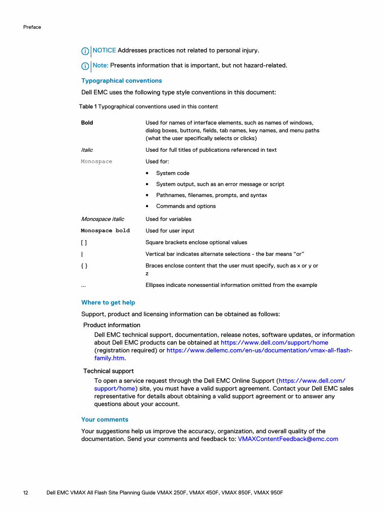
Typographical conventions
Dell EMC uses the following type style conventions in this document:
Table 1 Typographical conventions used in this content
Bold Used for names of interface elements, such as names of windows,dialog boxes, buttons, fields, tab names, key names, and menu paths(what the user specifically selects or clicks)
Italic Used for full titles of publications referenced in text
Monospace Used for:
l System code
l System output, such as an error message or script
l Pathnames, filenames, prompts, and syntax
l Commands and options
Monospace italic Used for variables
Monospace bold Used for user input
[ ] Square brackets enclose optional values
| Vertical bar indicates alternate selections - the bar means “or”
{ } Braces enclose content that the user must specify, such as x or y orz
... Ellipses indicate nonessential information omitted from the example
Where to get help
Support, product and licensing information can be obtained as follows:
Product information
Dell EMC technical support, documentation, release notes, software updates, or informationabout Dell EMC products can be obtained at https://www.dell.com/support/home(registration required) or https://www.dellemc.com/en-us/documentation/vmax-all-flash-family.htm.
Technical support
To open a service request through the Dell EMC Online Support (https://www.dell.com/support/home) site, you must have a valid support agreement. Contact your Dell EMC salesrepresentative for details about obtaining a valid support agreement or to answer anyquestions about your account.
Your comments
Your suggestions help us improve the accuracy, organization, and overall quality of thedocumentation. Send your comments and feedback to: [email protected]
Preface
12 Dell EMC VMAX All Flash Site Planning Guide VMAX 250F, VMAX 450F, VMAX 850F, VMAX 950F
Revision history
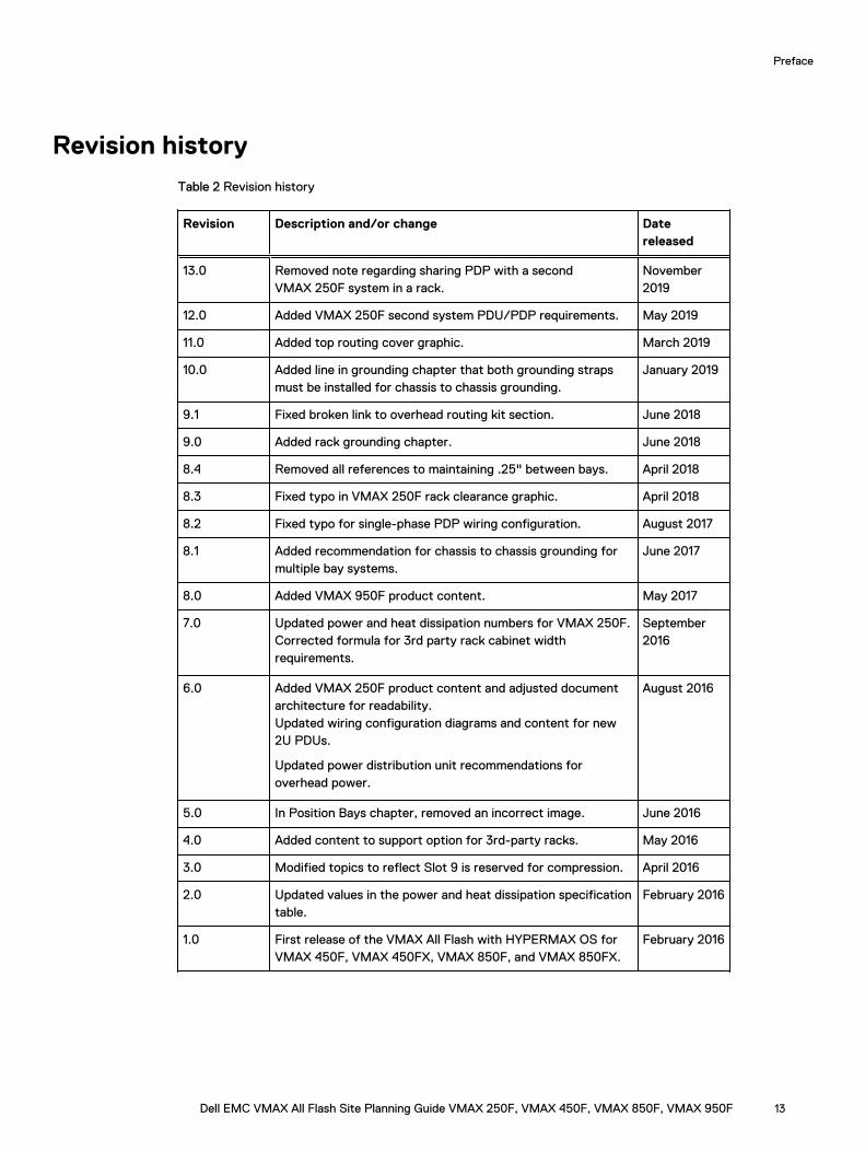
Table 2 Revision history
Revision Description and/or change Datereleased
13.0 Removed note regarding sharing PDP with a secondVMAX 250F system in a rack.
November2019
12.0 Added VMAX 250F second system PDU/PDP requirements. May 2019
11.0 Added top routing cover graphic. March 2019
10.0 Added line in grounding chapter that both grounding strapsmust be installed for chassis to chassis grounding.
January 2019
9.1 Fixed broken link to overhead routing kit section. June 2018
9.0 Added rack grounding chapter. June 2018
8.4 Removed all references to maintaining .25" between bays. April 2018
8.3 Fixed typo in VMAX 250F rack clearance graphic. April 2018
8.2 Fixed typo for single-phase PDP wiring configuration. August 2017
8.1 Added recommendation for chassis to chassis grounding formultiple bay systems.
June 2017
8.0 Added VMAX 950F product content. May 2017
7.0 Updated power and heat dissipation numbers for VMAX 250F.Corrected formula for 3rd party rack cabinet widthrequirements.
September2016
6.0 Added VMAX 250F product content and adjusted documentarchitecture for readability.Updated wiring configuration diagrams and content for new2U PDUs.
Updated power distribution unit recommendations foroverhead power.
August 2016
5.0 In Position Bays chapter, removed an incorrect image. June 2016
4.0 Added content to support option for 3rd-party racks. May 2016
3.0 Modified topics to reflect Slot 9 is reserved for compression. April 2016
2.0 Updated values in the power and heat dissipation specificationtable.
February 2016
1.0 First release of the VMAX All Flash with HYPERMAX OS forVMAX 450F, VMAX 450FX, VMAX 850F, and VMAX 850FX.
February 2016
Preface
Dell EMC VMAX All Flash Site Planning Guide VMAX 250F, VMAX 450F, VMAX 850F, VMAX 950F 13

Preface
14 Dell EMC VMAX All Flash Site Planning Guide VMAX 250F, VMAX 450F, VMAX 850F, VMAX 950F
CHAPTER 1
Pre-planning tasks
This chapter includes:
l Overview of data center requirements................................................................................... 16l VMAX All Flash packaging......................................................................................................16l Tasks to review...................................................................................................................... 16
Dell EMC VMAX All Flash Site Planning Guide VMAX 250F, VMAX 450F, VMAX 850F, VMAX 950F 15
Overview of data center requirementsVMAX All Flash arrays are designed for installation in data centers that provide:
l Sufficient physical space
l Controlled temperature and humidity
l Airflow and ventilation
l Power and grounding
l System cable routing facilities
l Fire protection
Raised floors are preferred.
For information regarding overhead cable routing, see Overhead routing kit on page 108.
To prepare the site for an array, meet with your Dell EMC Systems Engineer and CustomerEngineer to determine what is needed to prepare for delivery and installation. One or moresessions may be necessary to finalize installation plans.
VMAX All Flash packagingVMAX All Flash arrays offer the simplest packaging ever delivered for a platform. The basicbuilding block is an appliance-based entity called a V-Brick in open system arrays and a zBrick inmainframe arrays. Each V-Brick or zBrick includes:
l An engine with two directors (the redundant data storage processing unit)
l Flash capacity in Drive Array Enclosures (DAEs):
n VMAX 250F: Two 25-slot DAEs with a minimum base capacity of 13TBu
n VMAX 450F, VMAX 850F: Two 120-slot DAEs with a minimum base capacity of 53TBu
n VMAX 950F (open or mixed systems): Two 120-slot DAEs with a minimum base capacity of53TBu
n VMAX 950F (mainframe systems): Two 120-slot DAEs with a minimum base capacity of13TBu
l Multiple software packages are available: F and FX packages for open system arrays and zFand zFX for mainframe arrays.
This document uses the term V-Brick for planning purposes. All guidelines that apply to V-Bricksalso apply to zBricks.
Tasks to reviewThe following table provides a list of tasks to review during the planning process:
Table 3 Before you begin
Task Comments and/or Provide
Identify power requirements with customer andcustomer electrician.
External AC power must be supplied from anindependent customer-supplied power distribution unit(PDU).
Pre-planning tasks
16 Dell EMC VMAX All Flash Site Planning Guide VMAX 250F, VMAX 450F, VMAX 850F, VMAX 950F
Table 3 Before you begin (continued)
Task Comments and/or Provide
Dell EMC recommends that the customer’s electrician beavailable at the installation site for regular and third partyracked arrays.
Best Practices for AC Power Connections on page 113provides details.
For customer-supplied third party rack support, see thedetailed physical requirements in Third Party RackingOption for VMAX 250F on page 91 and Third PartyRacking Option for VMAX 450F, VMAX 850F and VMAX950F on page 97.
The field representative working the order must:
l Review the requisite information regarding the thirdparty racking option.
l In Sizer, select the desired configuration. In theHardware Options screen, under Rack Type, selectThird Party.
Complete the Installation Planning Task Sheet and PresiteSurvey in DXCX.
l Connection for ConnectEMC to dial home to the DellEMC Support Center. Data Center Safety andRemote Support on page 33 provides additionaldetails on remote support.
l Power, cooling and ventilation, humidity control,floor load capability, system placement, and serviceclearances as required in the data center.
Pre-planning tasks
Dell EMC VMAX All Flash Site Planning Guide VMAX 250F, VMAX 450F, VMAX 850F, VMAX 950F 17

Pre-planning tasks
18 Dell EMC VMAX All Flash Site Planning Guide VMAX 250F, VMAX 450F, VMAX 850F, VMAX 950F
CHAPTER 2
Delivery and transportation
This chapter includes:
l Delivery arrangements...........................................................................................................20l Pre-delivery considerations...................................................................................................20l Moving up and down inclines.................................................................................................20l Shipping and storage environmental requirements.................................................................21
Dell EMC VMAX All Flash Site Planning Guide VMAX 250F, VMAX 450F, VMAX 850F, VMAX 950F 19
Delivery arrangementsDelivery within the United States or Canada is by air-ride truck with custom-designed shippingmaterial, crate, and pallet. International delivery normally involves air freight.
Unless otherwise instructed, the Dell EMC Traffic Department arranges for delivery directly to thecustomer’s computer room. To ensure successful delivery of the system, Dell EMC has formedpartnerships with specially selected moving companies. These companies have movingprofessionals trained in the proper handling of large, sensitive equipment and provide theappropriate personnel, floor layments, and any ancillary moving equipment required to facilitatedelivery. Moving companies should check general guidelines, weights, and dimensions.
NOTICE Inform Dell EMC of any labor union-based restrictions or security clearancerequirements prior to delivery.
Pre-delivery considerationsTake into account the following considerations prior to the delivery at your site:
l Weight capacities of the loading dock, tailgate, and service elevator if delivery is to a floorother than the receiving floor.
l Length and thickness of covering required for floor protection.
l Equipment ramp availability if the receiving floor is not level with computer room floor.
l Set up the necessary network and gateway access to accommodate Secure Remote Servicesso that it will be available and operable for the installation date.
Moving up and down inclinesTo prevent tipping when moving up and down inclines, close all doors and drawers. Push from therear of the rack so that the front (side with bezels or a fancy door) goes first.
All portions of the bay will clear ramp and threshold slopes up to 1:10 (rise to run ratio), per Codeof Federal Regulations — ADA Standards for Accessible Design, 28 CFR Part 36.
Delivery and transportation
20 Dell EMC VMAX All Flash Site Planning Guide VMAX 250F, VMAX 450F, VMAX 850F, VMAX 950F
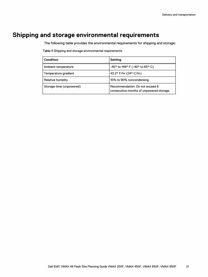
Shipping and storage environmental requirementsThe following table provides the environmental requirements for shipping and storage:
Table 4 Shipping and storage environmental requirements
Condition Setting
Ambient temperature -40° to 149° F (-40° to 65° C)
Temperature gradient 43.2° F/hr (24° C/hr)
Relative humidity 10% to 90% noncondensing
Storage time (unpowered) Recommendation: Do not exceed 6consecutive months of unpowered storage.
Delivery and transportation
Dell EMC VMAX All Flash Site Planning Guide VMAX 250F, VMAX 450F, VMAX 850F, VMAX 950F 21

Delivery and transportation
22 Dell EMC VMAX All Flash Site Planning Guide VMAX 250F, VMAX 450F, VMAX 850F, VMAX 950F
CHAPTER 3
Specifications
This chapter includes:
l Radio frequency interference................................................................................................ 24l Power consumption and heat dissipation...............................................................................25l Airflow...................................................................................................................................27l Air volume, air quality, and temperature................................................................................ 28l Shock and vibration...............................................................................................................30l Sound power and sound pressure..........................................................................................30l Hardware acclimation times................................................................................................... 31l Optical multimode cables....................................................................................................... 31
Dell EMC VMAX All Flash Site Planning Guide VMAX 250F, VMAX 450F, VMAX 850F, VMAX 950F 23
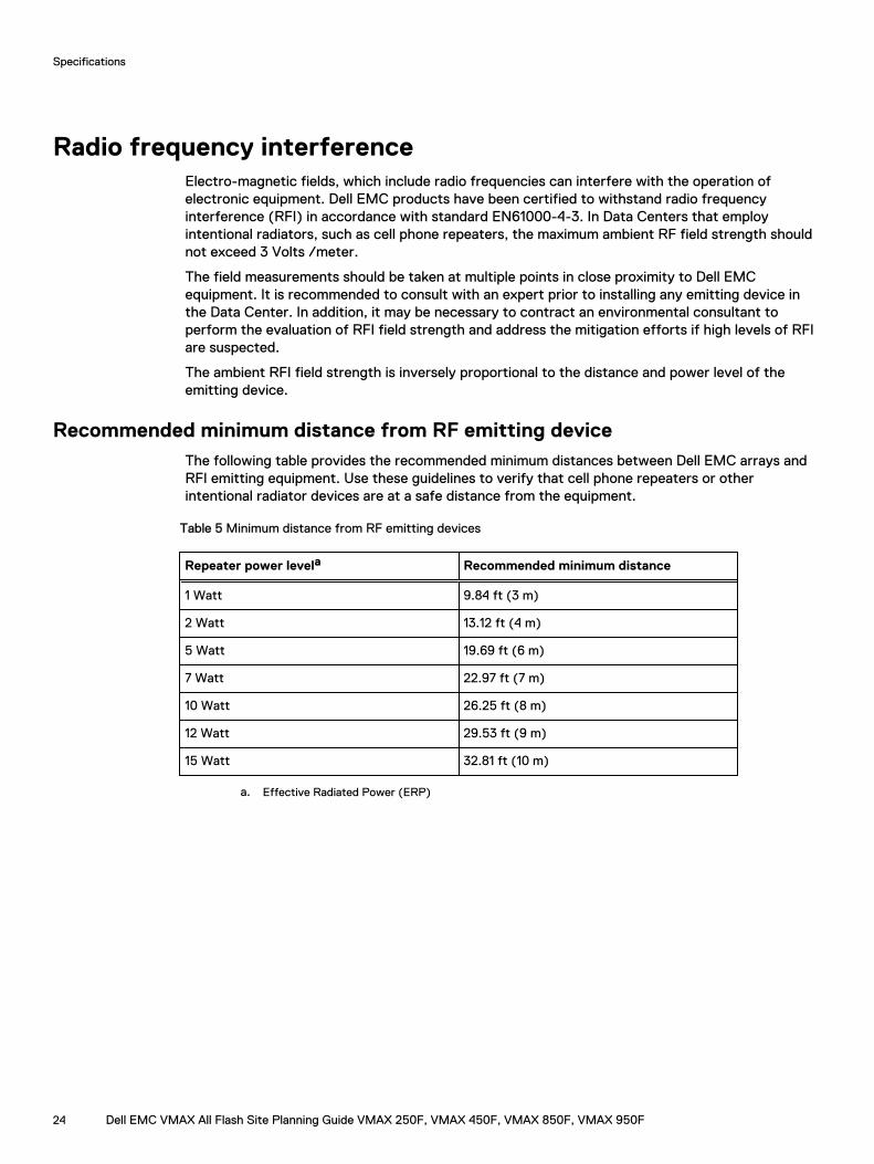
Radio frequency interferenceElectro-magnetic fields, which include radio frequencies can interfere with the operation ofelectronic equipment. Dell EMC products have been certified to withstand radio frequencyinterference (RFI) in accordance with standard EN61000-4-3. In Data Centers that employintentional radiators, such as cell phone repeaters, the maximum ambient RF field strength shouldnot exceed 3 Volts /meter.
The field measurements should be taken at multiple points in close proximity to Dell EMCequipment. It is recommended to consult with an expert prior to installing any emitting device inthe Data Center. In addition, it may be necessary to contract an environmental consultant toperform the evaluation of RFI field strength and address the mitigation efforts if high levels of RFIare suspected.
The ambient RFI field strength is inversely proportional to the distance and power level of theemitting device.
Recommended minimum distance from RF emitting deviceThe following table provides the recommended minimum distances between Dell EMC arrays andRFI emitting equipment. Use these guidelines to verify that cell phone repeaters or otherintentional radiator devices are at a safe distance from the equipment.
Table 5 Minimum distance from RF emitting devices
Repeater power levela Recommended minimum distance
1 Watt 9.84 ft (3 m)
2 Watt 13.12 ft (4 m)
5 Watt 19.69 ft (6 m)
7 Watt 22.97 ft (7 m)
10 Watt 26.25 ft (8 m)
12 Watt 29.53 ft (9 m)
15 Watt 32.81 ft (10 m)
a. Effective Radiated Power (ERP)
Specifications
24 Dell EMC VMAX All Flash Site Planning Guide VMAX 250F, VMAX 450F, VMAX 850F, VMAX 950F
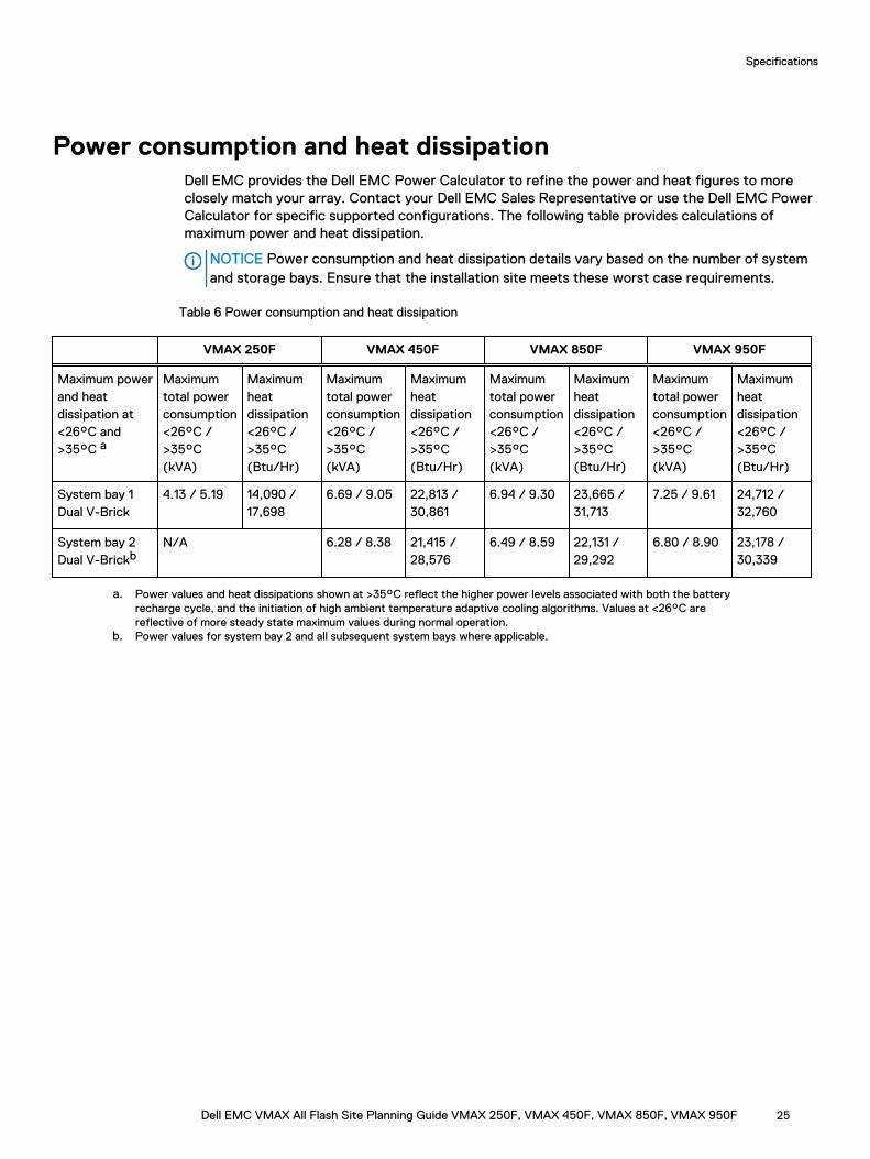
Power consumption and heat dissipationDell EMC provides the Dell EMC Power Calculator to refine the power and heat figures to moreclosely match your array. Contact your Dell EMC Sales Representative or use the Dell EMC PowerCalculator for specific supported configurations. The following table provides calculations ofmaximum power and heat dissipation.
NOTICE Power consumption and heat dissipation details vary based on the number of systemand storage bays. Ensure that the installation site meets these worst case requirements.
Table 6 Power consumption and heat dissipation
VMAX 250F VMAX 450F VMAX 850F VMAX 950F
Maximum powerand heatdissipation at<26°C and>35°C a
Maximumtotal powerconsumption<26°C />35°C(kVA)
Maximumheatdissipation<26°C />35°C(Btu/Hr)
Maximumtotal powerconsumption<26°C />35°C(kVA)
Maximumheatdissipation<26°C />35°C(Btu/Hr)
Maximumtotal powerconsumption<26°C />35°C(kVA)
Maximumheatdissipation<26°C />35°C(Btu/Hr)
Maximumtotal powerconsumption<26°C />35°C(kVA)
Maximumheatdissipation<26°C />35°C(Btu/Hr)
System bay 1Dual V-Brick
4.13 / 5.19 14,090 /17,698
6.69 / 9.05 22,813 /30,861
6.94 / 9.30 23,665 /31,713
7.25 / 9.61 24,712 /32,760
System bay 2Dual V-Brickb
N/A 6.28 / 8.38 21,415 /28,576
6.49 / 8.59 22,131 /29,292
6.80 / 8.90 23,178 /30,339
a. Power values and heat dissipations shown at >35°C reflect the higher power levels associated with both the batteryrecharge cycle, and the initiation of high ambient temperature adaptive cooling algorithms. Values at <26°C arereflective of more steady state maximum values during normal operation.
b. Power values for system bay 2 and all subsequent system bays where applicable.
Specifications
Dell EMC VMAX All Flash Site Planning Guide VMAX 250F, VMAX 450F, VMAX 850F, VMAX 950F 25
Adaptive coolingThe systems apply adaptive cooling based on customer environments to save energy. Engines andDAEs access thermal data through components located within their enclosures. Based on ambienttemperature and internal activity, they set the cooling fan speeds. As the inlet temperaturesincrease, the adaptive cooling increases the fan speeds, with the resulting platform powerincreasing up to the maximum values shown below. These values, along with the SPS rechargepower consumption, contribute to the maximum system power consumption values over 35°Cshown in Table 6 on page 25.
VMAX 250F
l DAE25 (25 Drives) = 7VA - 24 BTU/hr
l Engine = 255VA - 870 BTU/hr
VMAX 450F, VMAX 850F
l DAE120 (2.5 Drives) = 305VA - 1024 BTU/hr
l Engine = 180VA - 614 BTU/hr
VMAX 950F
l DAE120 (2.5 Drives) = 305VA - 1024 BTU/hr
l Engine = 255VA - 870 BTU/hr
Specifications
26 Dell EMC VMAX All Flash Site Planning Guide VMAX 250F, VMAX 450F, VMAX 850F, VMAX 950F
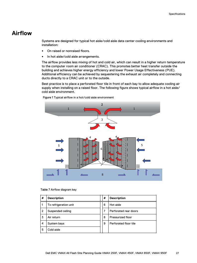
AirflowSystems are designed for typical hot aisle/cold aisle data center cooling environments andinstallation:
l On raised or nonraised floors.
l In hot aisle/cold aisle arrangements.
The airflow provides less mixing of hot and cold air, which can result in a higher return temperatureto the computer room air conditioner (CRAC). This promotes better heat transfer outside thebuilding and achieves higher energy efficiency and lower Power Usage Effectiveness (PUE).Additional efficiency can be achieved by sequestering the exhaust air completely and connectingducts directly to a CRAC unit or to the outside.
Best practice is to place a perforated floor tile in front of each bay to allow adequate cooling airsupply when installing on a raised floor. The following figure shows typical airflow in a hot aisle/cold aisle environment.
Figure 1 Typical airflow in a hot/cold aisle environment
5
6
5
4 4
8
7 99
1 1
22
3
Table 7 Airflow diagram key
# Description # Description
1 To refrigeration unit 6 Hot aisle
2 Suspended ceiling 7 Perforated rear doors
3 Air return 8 Pressurized floor
4 System bays 9 Perforated floor tile
5 Cold aisle
Specifications
Dell EMC VMAX All Flash Site Planning Guide VMAX 250F, VMAX 450F, VMAX 850F, VMAX 950F 27
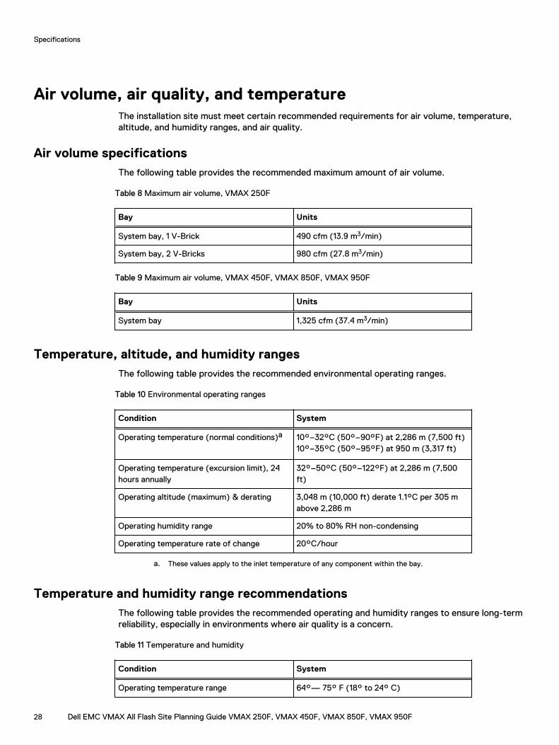
Air volume, air quality, and temperatureThe installation site must meet certain recommended requirements for air volume, temperature,altitude, and humidity ranges, and air quality.
Air volume specificationsThe following table provides the recommended maximum amount of air volume.
Table 8 Maximum air volume, VMAX 250F
Bay Units
System bay, 1 V-Brick 490 cfm (13.9 m3/min)
System bay, 2 V-Bricks 980 cfm (27.8 m3/min)
Table 9 Maximum air volume, VMAX 450F, VMAX 850F, VMAX 950F
Bay Units
System bay 1,325 cfm (37.4 m3/min)
Temperature, altitude, and humidity rangesThe following table provides the recommended environmental operating ranges.
Table 10 Environmental operating ranges
Condition System
Operating temperature (normal conditions)a 10°–32°C (50°–90°F) at 2,286 m (7,500 ft)10°–35°C (50°–95°F) at 950 m (3,317 ft)
Operating temperature (excursion limit), 24hours annually
32°–50°C (50°–122°F) at 2,286 m (7,500ft)
Operating altitude (maximum) & derating 3,048 m (10,000 ft) derate 1.1°C per 305 mabove 2,286 m
Operating humidity range 20% to 80% RH non-condensing
Operating temperature rate of change 20°C/hour
a. These values apply to the inlet temperature of any component within the bay.
Temperature and humidity range recommendationsThe following table provides the recommended operating and humidity ranges to ensure long-termreliability, especially in environments where air quality is a concern.
Table 11 Temperature and humidity
Condition System
Operating temperature range 64°— 75° F (18° to 24° C)
Specifications
28 Dell EMC VMAX All Flash Site Planning Guide VMAX 250F, VMAX 450F, VMAX 850F, VMAX 950F
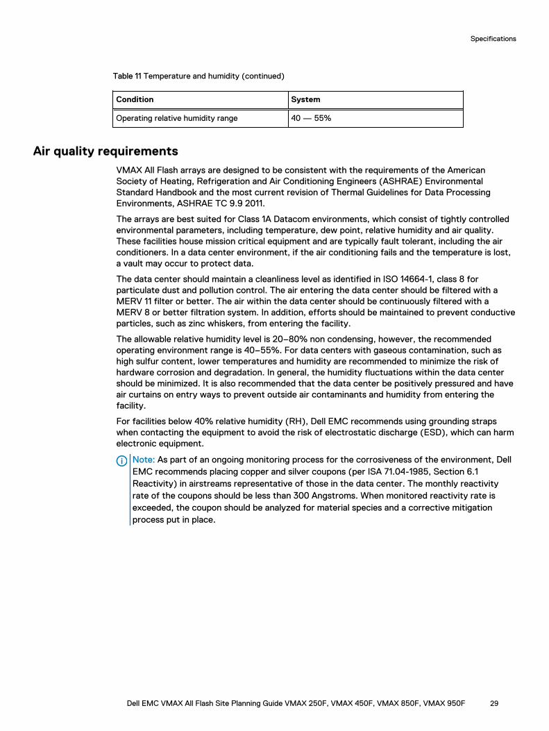
Table 11 Temperature and humidity (continued)
Condition System
Operating relative humidity range 40 — 55%
Air quality requirementsVMAX All Flash arrays are designed to be consistent with the requirements of the AmericanSociety of Heating, Refrigeration and Air Conditioning Engineers (ASHRAE) EnvironmentalStandard Handbook and the most current revision of Thermal Guidelines for Data ProcessingEnvironments, ASHRAE TC 9.9 2011.
The arrays are best suited for Class 1A Datacom environments, which consist of tightly controlledenvironmental parameters, including temperature, dew point, relative humidity and air quality.These facilities house mission critical equipment and are typically fault tolerant, including the airconditioners. In a data center environment, if the air conditioning fails and the temperature is lost,a vault may occur to protect data.
The data center should maintain a cleanliness level as identified in ISO 14664-1, class 8 forparticulate dust and pollution control. The air entering the data center should be filtered with aMERV 11 filter or better. The air within the data center should be continuously filtered with aMERV 8 or better filtration system. In addition, efforts should be maintained to prevent conductiveparticles, such as zinc whiskers, from entering the facility.
The allowable relative humidity level is 20–80% non condensing, however, the recommendedoperating environment range is 40–55%. For data centers with gaseous contamination, such ashigh sulfur content, lower temperatures and humidity are recommended to minimize the risk ofhardware corrosion and degradation. In general, the humidity fluctuations within the data centershould be minimized. It is also recommended that the data center be positively pressured and haveair curtains on entry ways to prevent outside air contaminants and humidity from entering thefacility.
For facilities below 40% relative humidity (RH), Dell EMC recommends using grounding strapswhen contacting the equipment to avoid the risk of electrostatic discharge (ESD), which can harmelectronic equipment.
Note: As part of an ongoing monitoring process for the corrosiveness of the environment, DellEMC recommends placing copper and silver coupons (per ISA 71.04-1985, Section 6.1Reactivity) in airstreams representative of those in the data center. The monthly reactivityrate of the coupons should be less than 300 Angstroms. When monitored reactivity rate isexceeded, the coupon should be analyzed for material species and a corrective mitigationprocess put in place.
Specifications
Dell EMC VMAX All Flash Site Planning Guide VMAX 250F, VMAX 450F, VMAX 850F, VMAX 950F 29
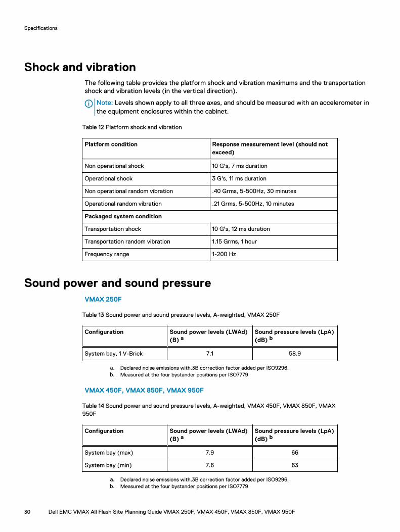
Shock and vibrationThe following table provides the platform shock and vibration maximums and the transportationshock and vibration levels (in the vertical direction).
Note: Levels shown apply to all three axes, and should be measured with an accelerometer inthe equipment enclosures within the cabinet.
Table 12 Platform shock and vibration
Platform condition Response measurement level (should notexceed)
Non operational shock 10 G's, 7 ms duration
Operational shock 3 G's, 11 ms duration
Non operational random vibration .40 Grms, 5-500Hz, 30 minutes
Operational random vibration .21 Grms, 5-500Hz, 10 minutes
Packaged system condition
Transportation shock 10 G's, 12 ms duration
Transportation random vibration 1.15 Grms, 1 hour
Frequency range 1-200 Hz
Sound power and sound pressureVMAX 250F
Table 13 Sound power and sound pressure levels, A-weighted, VMAX 250F
Configuration Sound power levels (LWAd)(B) a
Sound pressure levels (LpA)(dB) b
System bay, 1 V-Brick 7.1 58.9
a. Declared noise emissions with.3B correction factor added per ISO9296.b. Measured at the four bystander positions per ISO7779
VMAX 450F, VMAX 850F, VMAX 950F
Table 14 Sound power and sound pressure levels, A-weighted, VMAX 450F, VMAX 850F, VMAX950F
Configuration Sound power levels (LWAd)(B) a
Sound pressure levels (LpA)(dB) b
System bay (max) 7.9 66
System bay (min) 7.6 63
a. Declared noise emissions with.3B correction factor added per ISO9296.b. Measured at the four bystander positions per ISO7779
Specifications
30 Dell EMC VMAX All Flash Site Planning Guide VMAX 250F, VMAX 450F, VMAX 850F, VMAX 950F
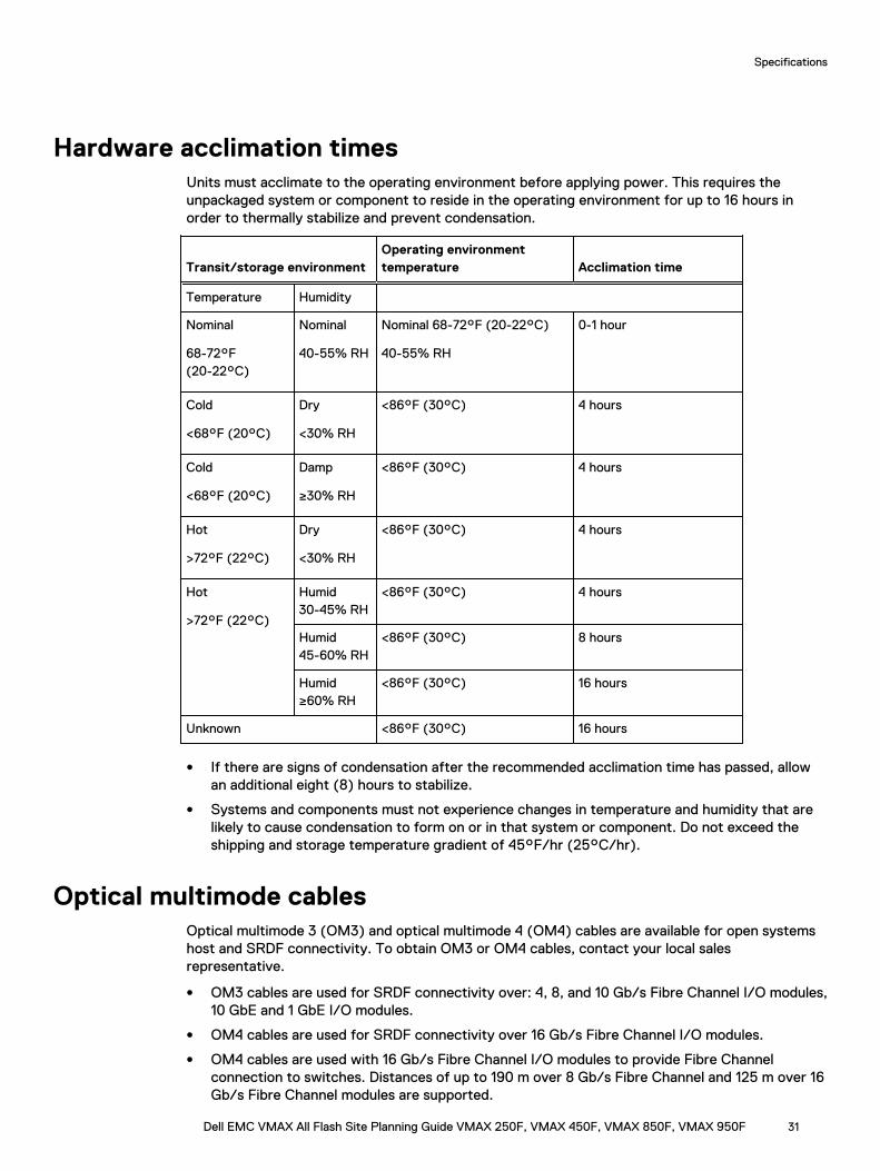
Hardware acclimation timesUnits must acclimate to the operating environment before applying power. This requires theunpackaged system or component to reside in the operating environment for up to 16 hours inorder to thermally stabilize and prevent condensation.
Transit/storage environmentOperating environmenttemperature Acclimation time
Temperature Humidity
Nominal
68-72°F(20-22°C)
Nominal
40-55% RH
Nominal 68-72°F (20-22°C)
40-55% RH
0-1 hour
Cold
<68°F (20°C)
Dry
<30% RH
<86°F (30°C) 4 hours
Cold
<68°F (20°C)
Damp
≥30% RH
<86°F (30°C) 4 hours
Hot
>72°F (22°C)
Dry
<30% RH
<86°F (30°C) 4 hours
Hot
>72°F (22°C)
Humid30-45% RH
<86°F (30°C) 4 hours
Humid45-60% RH
<86°F (30°C) 8 hours
Humid≥60% RH
<86°F (30°C) 16 hours
Unknown <86°F (30°C) 16 hours
l If there are signs of condensation after the recommended acclimation time has passed, allowan additional eight (8) hours to stabilize.
l Systems and components must not experience changes in temperature and humidity that arelikely to cause condensation to form on or in that system or component. Do not exceed theshipping and storage temperature gradient of 45°F/hr (25°C/hr).
Optical multimode cablesOptical multimode 3 (OM3) and optical multimode 4 (OM4) cables are available for open systemshost and SRDF connectivity. To obtain OM3 or OM4 cables, contact your local salesrepresentative.
l OM3 cables are used for SRDF connectivity over: 4, 8, and 10 Gb/s Fibre Channel I/O modules,10 GbE and 1 GbE I/O modules.
l OM4 cables are used for SRDF connectivity over 16 Gb/s Fibre Channel I/O modules.
l OM4 cables are used with 16 Gb/s Fibre Channel I/O modules to provide Fibre Channelconnection to switches. Distances of up to 190 m over 8 Gb/s Fibre Channel and 125 m over 16Gb/s Fibre Channel modules are supported.
Specifications
Dell EMC VMAX All Flash Site Planning Guide VMAX 250F, VMAX 450F, VMAX 850F, VMAX 950F 31
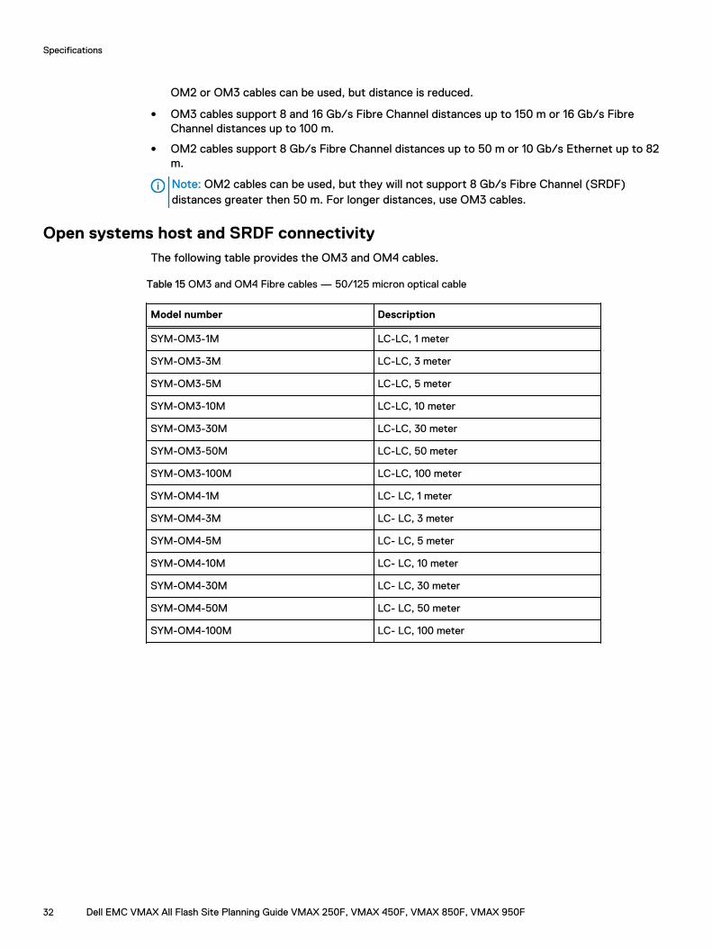
OM2 or OM3 cables can be used, but distance is reduced.
l OM3 cables support 8 and 16 Gb/s Fibre Channel distances up to 150 m or 16 Gb/s FibreChannel distances up to 100 m.
l OM2 cables support 8 Gb/s Fibre Channel distances up to 50 m or 10 Gb/s Ethernet up to 82m.
Note: OM2 cables can be used, but they will not support 8 Gb/s Fibre Channel (SRDF)distances greater then 50 m. For longer distances, use OM3 cables.
Open systems host and SRDF connectivityThe following table provides the OM3 and OM4 cables.
Table 15 OM3 and OM4 Fibre cables — 50/125 micron optical cable
Model number Description
SYM-OM3-1M LC-LC, 1 meter
SYM-OM3-3M LC-LC, 3 meter
SYM-OM3-5M LC-LC, 5 meter
SYM-OM3-10M LC-LC, 10 meter
SYM-OM3-30M LC-LC, 30 meter
SYM-OM3-50M LC-LC, 50 meter
SYM-OM3-100M LC-LC, 100 meter
SYM-OM4-1M LC- LC, 1 meter
SYM-OM4-3M LC- LC, 3 meter
SYM-OM4-5M LC- LC, 5 meter
SYM-OM4-10M LC- LC, 10 meter
SYM-OM4-30M LC- LC, 30 meter
SYM-OM4-50M LC- LC, 50 meter
SYM-OM4-100M LC- LC, 100 meter
Specifications
32 Dell EMC VMAX All Flash Site Planning Guide VMAX 250F, VMAX 450F, VMAX 850F, VMAX 950F

CHAPTER 4
Data Center Safety and Remote Support
This chapter includes:
l Fire suppressant disclaimer................................................................................................... 34l Remote support.....................................................................................................................34
Dell EMC VMAX All Flash Site Planning Guide VMAX 250F, VMAX 450F, VMAX 850F, VMAX 950F 33

Fire suppressant disclaimerFire prevention equipment in the computer room should always be installed as an added safetymeasure. A fire suppression system is the responsibility of the customer. When selectingappropriate fire suppression equipment and agents for the data center, choose carefully. Aninsurance underwriter, local fire marshal, and local building inspector are all parties that you shouldconsult during the selection of a fire suppression system that provides the correct level ofcoverage and protection.
Equipment is designed and manufactured to internal and external standards that require certainenvironments for reliable operation. We do not make compatibility claims of any kind nor do weprovide recommendations on fire suppression systems. It is not recommended to position storageequipment directly in the path of high pressure gas discharge streams or loud fire sirens so as tominimize the forces and vibration adverse to system integrity.
Note: The previous information is provided on an “as is” basis and provides no representations,warranties, guarantees or obligations on the part of our company. This information does notmodify the scope of any warranty set forth in the terms and conditions of the basic purchasingagreement between the customer and the manufacturer.
Remote supportSecure Remote Services is an IP-based, automated, connect home and remote support solution.Secure Remote Services is the preferred method of connectivity. Two connections with SecureRemote Services are recommended for connection to the redundant management module controlstation (MMCS).
Customers of Secure Remote Services must provide the following:
l An IP network with Internet connectivity.
l Capability to add Gateway Client servers and Policy Manager servers to the customer network.
l Network connectivity between the servers and Dell EMC devices to be managed by SecureRemote Services.
l Internet connectivity to the Secure Remote Services infrastructure by using outbound ports.
l Network connectivity between Secure Remote Services Client(s) and Policy Manager.
Once installed, Secure Remote Services monitors the array and automatically notifies Dell EMCCustomer Service in the event of a problem. If an error is detected, a support professional utilizesthe secure connection to establish a remote support session to diagnose, and if necessary,perform a repair.
Customer Service can use Secure Remote Services to:
l Perform downloads of updated software in lieu of a site visit.
l Deliver license entitlements directly to the array.
NOTICE Dell EMC provides an optional modem that uses a regular telephone line or operateswith a PBX. Dell EMC recommends using two connections to the redundant managementmodule control station (MMCS).
The Dell EMC Secure Remote Services Site Planning Guide provides additional information.
Data Center Safety and Remote Support
34 Dell EMC VMAX All Flash Site Planning Guide VMAX 250F, VMAX 450F, VMAX 850F, VMAX 950F
CHAPTER 5
Physical weight and space
This chapter includes:
l Floor load-bearing capacity................................................................................................... 36l Raised floor requirements......................................................................................................36l Physical space and weight.....................................................................................................37
Dell EMC VMAX All Flash Site Planning Guide VMAX 250F, VMAX 450F, VMAX 850F, VMAX 950F 35
Floor load-bearing capacityStorage arrays can be installed on raised floors. Customers must be aware that the load-bearingcapacity of the data center floor is not readily available through a visual inspection of the floor. Theonly definitive way to ensure that the floor is capable of supporting the load associated with thearray is to have a certified architect or the data center design consultant inspect the specificationsof the floor to ensure that the floor is capable of supporting the array weight.
CAUTION
l Customers are ultimately responsible for ensuring that the floor of the data center onwhich the array is to be configured is capable of supporting the array weight, whether thearray is configured directly on the data center floor or on a raised floor supported by thedata center floor.
l Failure to comply with these floor loading requirements could result in severe damage tothe storage array, the raised floor, subfloor, site floor and the surrounding infrastructureshould the raised floor, subfloor or site floor fail.
l Notwithstanding anything to the contrary in any agreement between Dell EMC and thecustomer, Dell EMC fully disclaims any and all liability for any damage or injury resultingfrom the customer’s failure to ensure that the raised floor, subfloor and/or site floor arecapable of supporting the storage array weight. The customer assumes all risk and liabilityassociated with such failure.
Raised floor requirementsBest practice is to use 24 x 24 inch heavy-duty, concrete-filled steel floor tiles. If a different sizeor type of tile is used, the customer must ensure that the tiles have a minimum load rating that issufficient for supporting the storage array weight. Ensure proper physical support of the systemby following requirements that are based on the use of 24 x 24 in. (61 x 61 cm) heavy-duty,concrete-filled steel floor tiles.
Raised floors must meet the following requirements:
l Floor must be level.
l Floor tiles and stringers must be rated to withstand concentrated loads of two casters eachthat weigh up to 700 lb (317.5 kg).
Note: Caster weights are measured on a level floor. The front of the array weighs more thanthe rear of the configuration.
l Floor tiles and stringers must be rated for a minimum static ultimate load of 3,000 lb (1,360.8kg).
l Floor tiles must be rated for a minimum of 1,000 lb (453.6 kg) on rolling load.
l For floor tiles that do not meet the minimum rolling load rate, Dell EMC recommends the use ofcoverings, such as plywood, to protect floors during system roll.
l Floor tile cutouts weaken the tile. An additional pedestal mount adjacent to the cutout of a tilecan minimize floor tile deflection. The number and placement of additional pedestal mountsrelative to a cutout should be in accordance with the tile manufacturer’s recommendations.
l Take care when positioning the bays to make sure that a caster is not moved into a cutout.Cutting tiles per specifications ensures the proper caster placement.
Physical weight and space
36 Dell EMC VMAX All Flash Site Planning Guide VMAX 250F, VMAX 450F, VMAX 850F, VMAX 950F
l Use or create no more than one floor tile cutout that is no more than 8 in. (20 cm) wide by 6 in.(15 cm) deep in each 24 x 24 in. (61 x 61 cm) floor tile.
l Ensure that the weight of any other objects in the data center does not compromise thestructural integrity of the raised floor or the sub-floor (non-raised floor) of the data center.
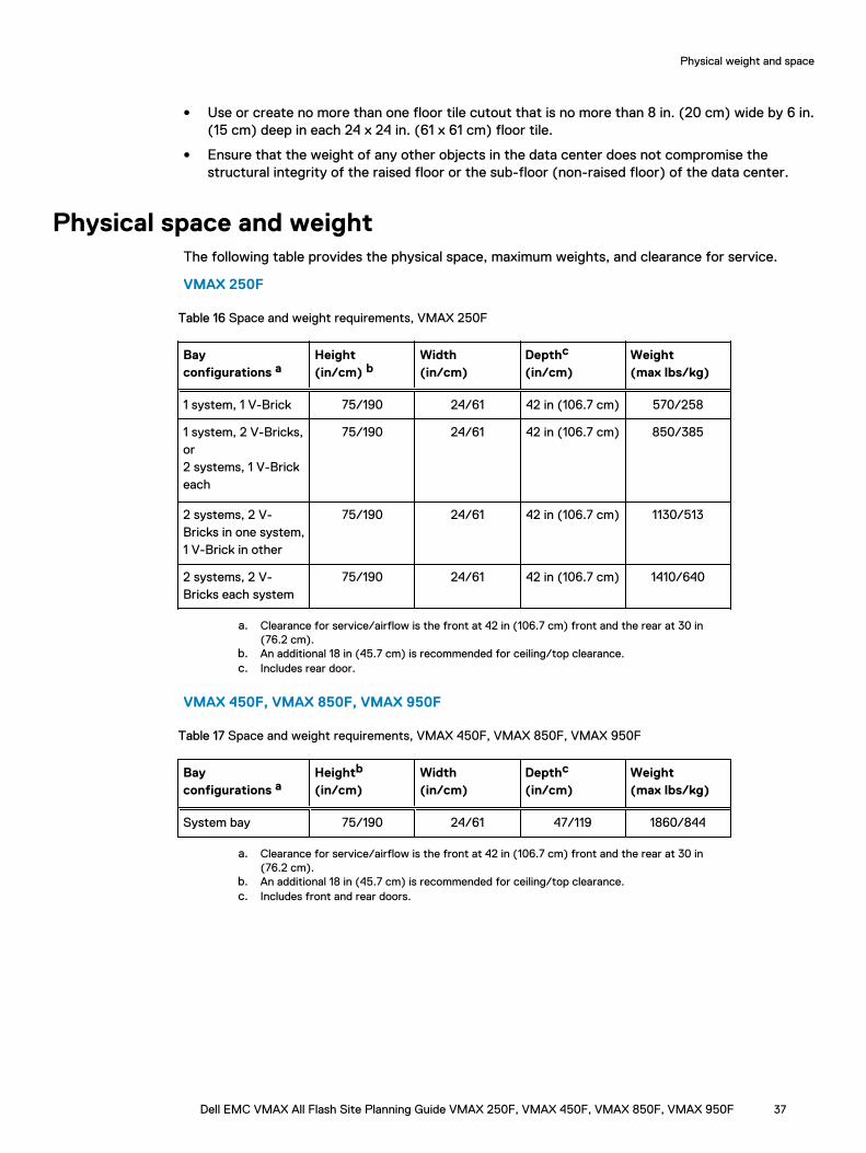
Physical space and weightThe following table provides the physical space, maximum weights, and clearance for service.
VMAX 250F
Table 16 Space and weight requirements, VMAX 250F
Bayconfigurations a
Height(in/cm) b
Width(in/cm)
Depthc
(in/cm)Weight(max lbs/kg)
1 system, 1 V-Brick 75/190 24/61 42 in (106.7 cm) 570/258
1 system, 2 V-Bricks,or2 systems, 1 V-Brickeach
75/190 24/61 42 in (106.7 cm) 850/385
2 systems, 2 V-Bricks in one system,1 V-Brick in other
75/190 24/61 42 in (106.7 cm) 1130/513
2 systems, 2 V-Bricks each system
75/190 24/61 42 in (106.7 cm) 1410/640
a. Clearance for service/airflow is the front at 42 in (106.7 cm) front and the rear at 30 in(76.2 cm).
b. An additional 18 in (45.7 cm) is recommended for ceiling/top clearance.c. Includes rear door.
VMAX 450F, VMAX 850F, VMAX 950F
Table 17 Space and weight requirements, VMAX 450F, VMAX 850F, VMAX 950F
Bayconfigurations a
Heightb
(in/cm)Width(in/cm)
Depthc
(in/cm)Weight(max lbs/kg)
System bay 75/190 24/61 47/119 1860/844
a. Clearance for service/airflow is the front at 42 in (106.7 cm) front and the rear at 30 in(76.2 cm).
b. An additional 18 in (45.7 cm) is recommended for ceiling/top clearance.c. Includes front and rear doors.
Physical weight and space
Dell EMC VMAX All Flash Site Planning Guide VMAX 250F, VMAX 450F, VMAX 850F, VMAX 950F 37

Physical weight and space
38 Dell EMC VMAX All Flash Site Planning Guide VMAX 250F, VMAX 450F, VMAX 850F, VMAX 950F
CHAPTER 6
Position VMAX 250F Bay
This chapter includes:
l Bay layout and dimensions.................................................................................................... 40l Tile placement........................................................................................................................41l Casters and leveling feet........................................................................................................41l Cabinet stabilizing................................................................................................................. 43
Dell EMC VMAX All Flash Site Planning Guide VMAX 250F, VMAX 450F, VMAX 850F, VMAX 950F 39
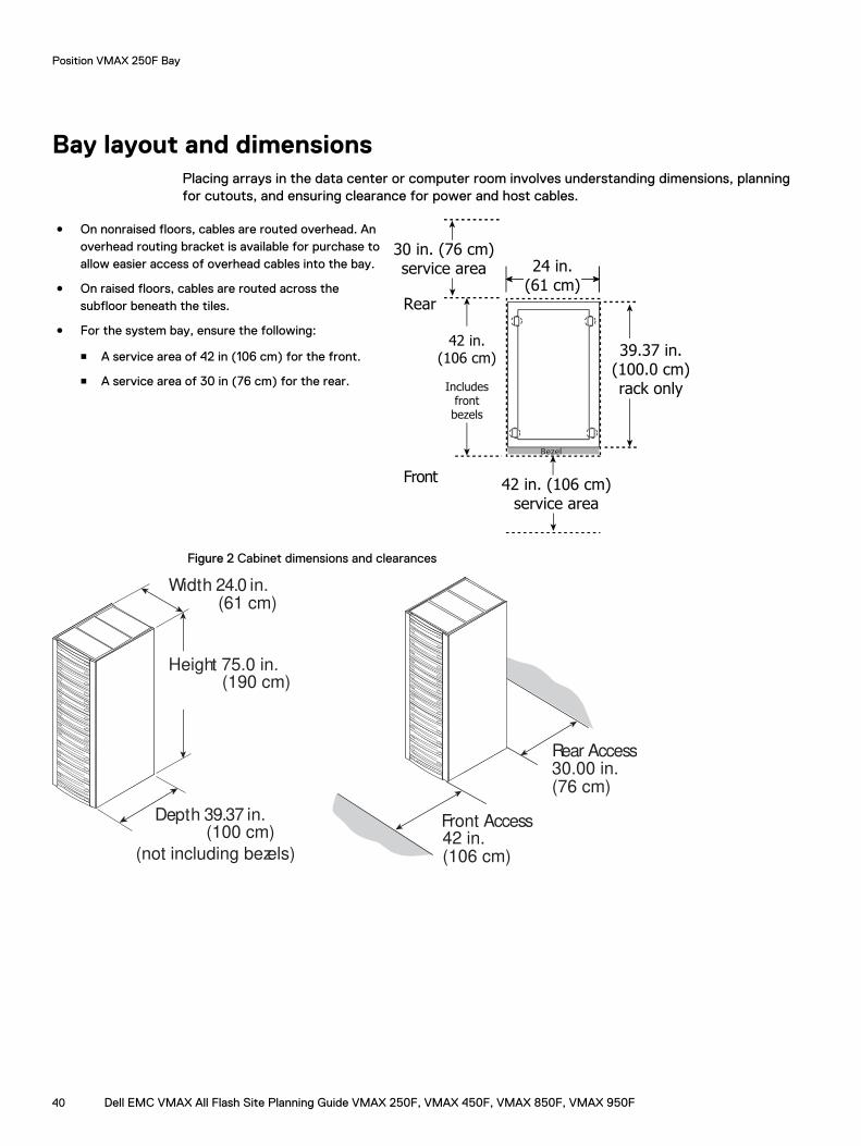
Bay layout and dimensionsPlacing arrays in the data center or computer room involves understanding dimensions, planningfor cutouts, and ensuring clearance for power and host cables.
l On nonraised floors, cables are routed overhead. Anoverhead routing bracket is available for purchase toallow easier access of overhead cables into the bay.
l On raised floors, cables are routed across thesubfloor beneath the tiles.
l For the system bay, ensure the following:
n A service area of 42 in (106 cm) for the front.
n A service area of 30 in (76 cm) for the rear.
Front
Rear
24.02 in.(61.01 cm)
24 in.(61 cm)
Bezel
39.37 in.(100.0 cm)rack only
42 in.(106 cm)
Includesfrontbezels
42 in. (106 cm)service area
30 in. (76 cm)service area
Figure 2 Cabinet dimensions and clearances
Height 75.0 in.(190 cm)
Depth 39.37 in.(100 cm)
(not including bezels)
Width 24.0 in.(61 cm)
Rear Access
(76 cm)30.00 in.
Front Access
(106 cm)42 in.
Position VMAX 250F Bay
40 Dell EMC VMAX All Flash Site Planning Guide VMAX 250F, VMAX 450F, VMAX 850F, VMAX 950F
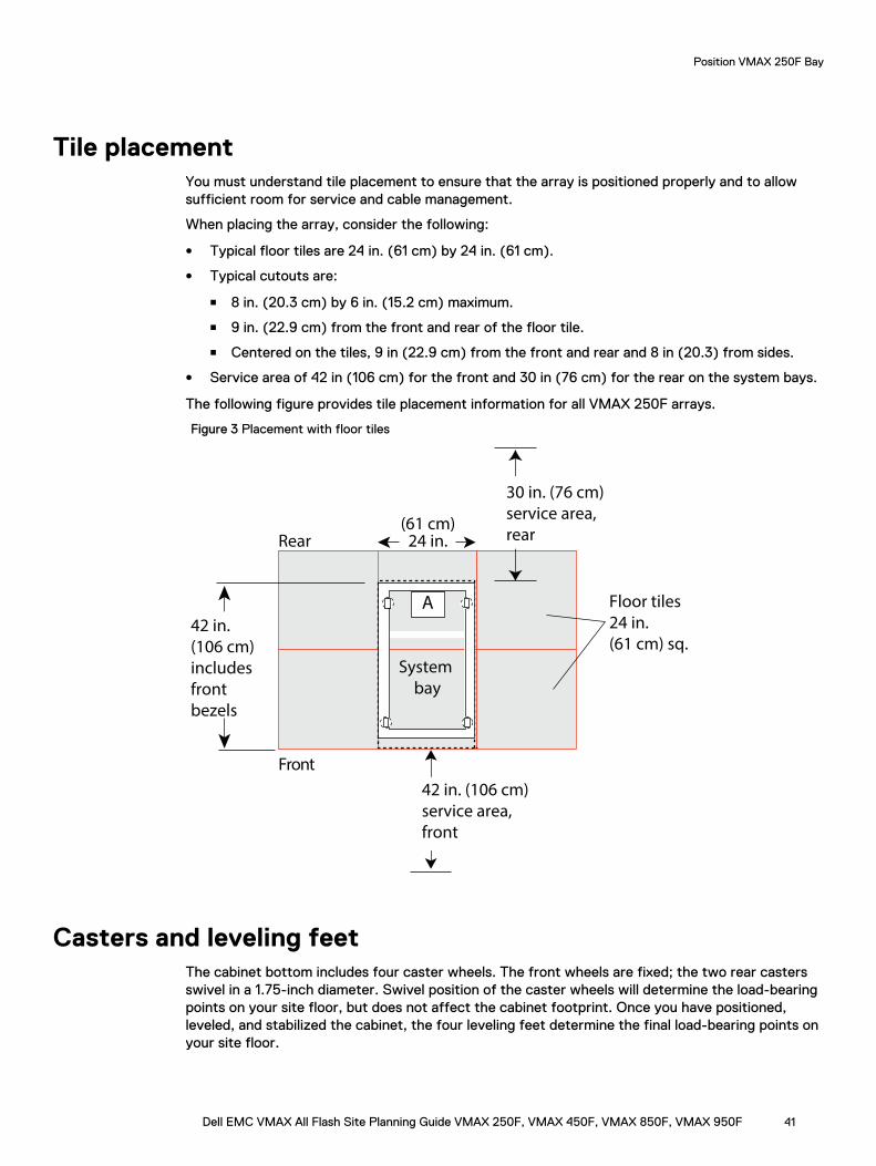
Tile placementYou must understand tile placement to ensure that the array is positioned properly and to allowsufficient room for service and cable management.
When placing the array, consider the following:
l Typical floor tiles are 24 in. (61 cm) by 24 in. (61 cm).
l Typical cutouts are:
n 8 in. (20.3 cm) by 6 in. (15.2 cm) maximum.
n 9 in. (22.9 cm) from the front and rear of the floor tile.
n Centered on the tiles, 9 in (22.9 cm) from the front and rear and 8 in (20.3) from sides.
l Service area of 42 in (106 cm) for the front and 30 in (76 cm) for the rear on the system bays.
The following figure provides tile placement information for all VMAX 250F arrays.
Figure 3 Placement with floor tiles
A
Front
Rear
System
bay
Floor tiles
24 in.
(61 cm) sq.
42 in. (106 cm)
service area,
front
30 in. (76 cm)
service area,
rear(61 cm)
24 in.
42 in.
(106 cm)
includes
front
bezels
Casters and leveling feetThe cabinet bottom includes four caster wheels. The front wheels are fixed; the two rear castersswivel in a 1.75-inch diameter. Swivel position of the caster wheels will determine the load-bearingpoints on your site floor, but does not affect the cabinet footprint. Once you have positioned,leveled, and stabilized the cabinet, the four leveling feet determine the final load-bearing points onyour site floor.
Position VMAX 250F Bay
Dell EMC VMAX All Flash Site Planning Guide VMAX 250F, VMAX 450F, VMAX 850F, VMAX 950F 41
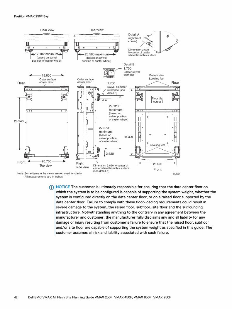
CL3627
Front
Rear
Front
RearOuter surfaceof rear door
Outer surfaceof rear door
18.830
20.700
28.240
(based on swivelposition of caster wheel)
17.102 minimum(based on swivel
position of caster wheel)
20.580 maximum
Top view
Rear view Rear view
Note: Some items in the views are removed for clarity.
Right
side viewDimension 3.620 to center ofcaster wheel from this surface(see detail A)
Dimension 3.620 to center of caster wheel from this surface
3.620
27.370
minimum(based onswivel positionof caster wheel)
29.120
maximum(based onswivel positionof caster wheel)
1.750Swivel diameterreference (seedetail B)
Detail A(right frontcorner)
1.750Caster swiveldiameter
Detail B
20.650
35.390
Bottom view
Leveling feet
Leveling feet
Floor tile
cutout
All measurements are in inches.
NOTICE The customer is ultimately responsible for ensuring that the data center floor onwhich the system is to be configured is capable of supporting the system weight, whether thesystem is configured directly on the data center floor, or on a raised floor supported by thedata center floor. Failure to comply with these floor-loading requirements could result insevere damage to the system, the raised floor, subfloor, site floor and the surroundinginfrastructure. Notwithstanding anything to the contrary in any agreement between themanufacturer and customer, the manufacturer fully disclaims any and all liability for anydamage or injury resulting from customer's failure to ensure that the raised floor, subfloorand/or site floor are capable of supporting the system weight as specified in this guide. Thecustomer assumes all risk and liability associated with such failure.
Position VMAX 250F Bay
42 Dell EMC VMAX All Flash Site Planning Guide VMAX 250F, VMAX 450F, VMAX 850F, VMAX 950F

Cabinet stabilizingIf you intend to secure the optional stabilizer brackets to the site floor, prepare the location for themounting bolts. The seismic restraint bracket provides protection from moving and tipping, helpingto prevent the cabinet from tipping while you service cantilevered levels or from rolling duringminor seismic events.
Figure 4 Seismic restraint bracket
42.88
40.88
8.305.92
28.03
.438
3.55
2.00
2.00
16.60
24.90 .50
8.46
16.92
21.25
30.03
EMC2856
Fro
nt
Rear
All measurements are in inches.
29.23
Position VMAX 250F Bay
Dell EMC VMAX All Flash Site Planning Guide VMAX 250F, VMAX 450F, VMAX 850F, VMAX 950F 43

Position VMAX 250F Bay
44 Dell EMC VMAX All Flash Site Planning Guide VMAX 250F, VMAX 450F, VMAX 850F, VMAX 950F
CHAPTER 7
Position VMAX 450F, VMAX 850F, VMAX 950FBays
This chapter includes:
l System bay layouts............................................................................................................... 46l Dimensions for array layouts................................................................................................. 49l Tile placement.......................................................................................................................50l Caster and leveler dimensions............................................................................................... 50
Dell EMC VMAX All Flash Site Planning Guide VMAX 250F, VMAX 450F, VMAX 850F, VMAX 950F 45
System bay layoutsThe number of bays and the system layout depend on the array model, the customer requirements,and the space and organization of the customer data center.
Storage arrays can be placed in the following layouts:
l Adjacent — bays are positioned side-by-side.
l Dispersed — dispersed layouts are provided with longer fabric and Ethernet cable bundles thatallow 82 ft (25 m) of separation between system bay 1 and system bays 2 through 4.
Dispersed system bays require dispersed cable and optics kits and one set of side skins foreach dispersed system bay in the configuration.
l Adjacent and dispersed bays (mixed) layouts — allow both adjacent and dispersed layoutwithin a single array.
Position VMAX 450F, VMAX 850F, VMAX 950F Bays
46 Dell EMC VMAX All Flash Site Planning Guide VMAX 250F, VMAX 450F, VMAX 850F, VMAX 950F
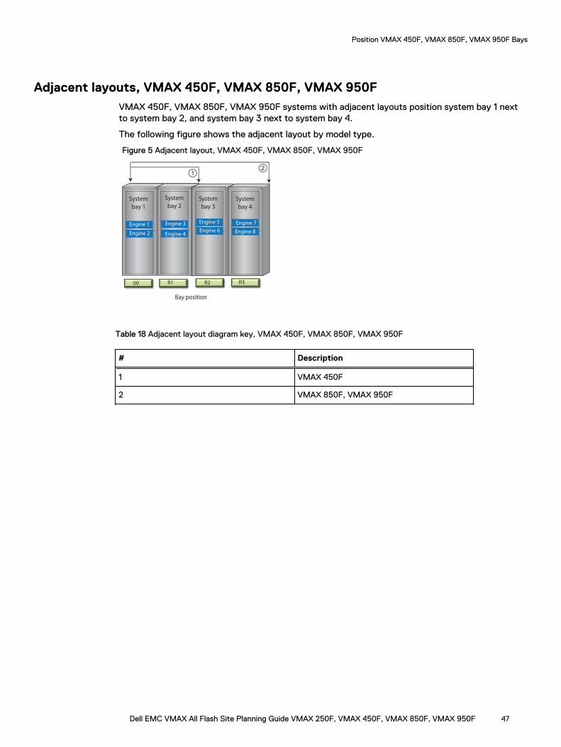
Adjacent layouts, VMAX 450F, VMAX 850F, VMAX 950FVMAX 450F, VMAX 850F, VMAX 950F systems with adjacent layouts position system bay 1 nextto system bay 2, and system bay 3 next to system bay 4.
The following figure shows the adjacent layout by model type.
Figure 5 Adjacent layout, VMAX 450F, VMAX 850F, VMAX 950F
System
bay 1
System
bay 2
Engine 1
Engine 2 Engine 4
Engine 3
00 R1
System
bay 3
System
bay 4
Engine 5 Engine 7
Engine 8Engine 6
R2 R3
Bay position
12
Table 18 Adjacent layout diagram key, VMAX 450F, VMAX 850F, VMAX 950F
# Description
1 VMAX 450F
2 VMAX 850F, VMAX 950F
Position VMAX 450F, VMAX 850F, VMAX 950F Bays
Dell EMC VMAX All Flash Site Planning Guide VMAX 250F, VMAX 450F, VMAX 850F, VMAX 950F 47
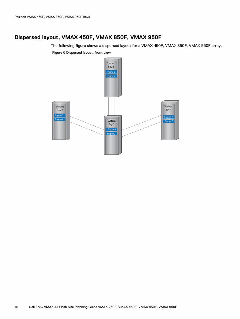
Dispersed layout, VMAX 450F, VMAX 850F, VMAX 950FThe following figure shows a dispersed layout for a VMAX 450F, VMAX 850F, VMAX 950F array.
Figure 6 Dispersed layout, front view
System
bay 1
Engine 7
Engine 2
Engine 1
Engine 8
Engine 5
Engine 6
Engine 3
Engine 4
System
Bay 2
System
Bay 1
System
Bay 3
System
Bay 4
Position VMAX 450F, VMAX 850F, VMAX 950F Bays
48 Dell EMC VMAX All Flash Site Planning Guide VMAX 250F, VMAX 450F, VMAX 850F, VMAX 950F
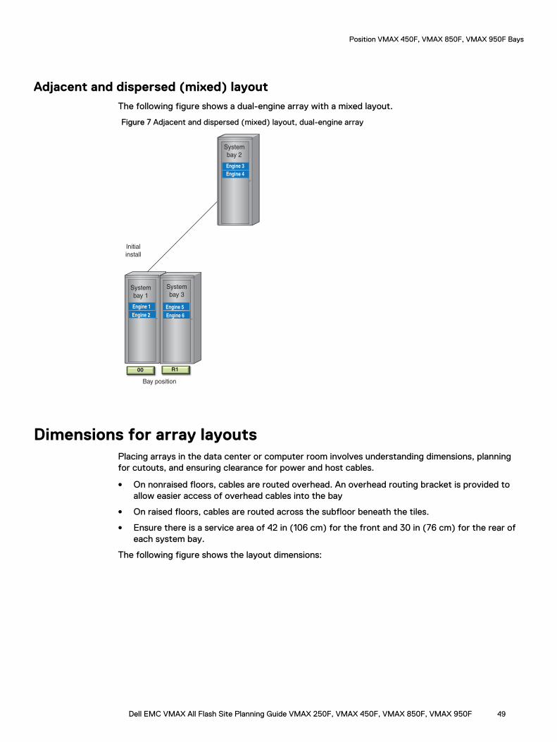
Adjacent and dispersed (mixed) layoutThe following figure shows a dual-engine array with a mixed layout.
Figure 7 Adjacent and dispersed (mixed) layout, dual-engine array
System
bay 1
Engine 1
Initial
install
System
bay 2
Engine 3
Engine 2
Engine 4
System
bay 3
Engine 5
Engine 6
00 R1
Bay position
Dimensions for array layoutsPlacing arrays in the data center or computer room involves understanding dimensions, planningfor cutouts, and ensuring clearance for power and host cables.
l On nonraised floors, cables are routed overhead. An overhead routing bracket is provided toallow easier access of overhead cables into the bay
l On raised floors, cables are routed across the subfloor beneath the tiles.
l Ensure there is a service area of 42 in (106 cm) for the front and 30 in (76 cm) for the rear ofeach system bay.
The following figure shows the layout dimensions:
Position VMAX 450F, VMAX 850F, VMAX 950F Bays
Dell EMC VMAX All Flash Site Planning Guide VMAX 250F, VMAX 450F, VMAX 850F, VMAX 950F 49
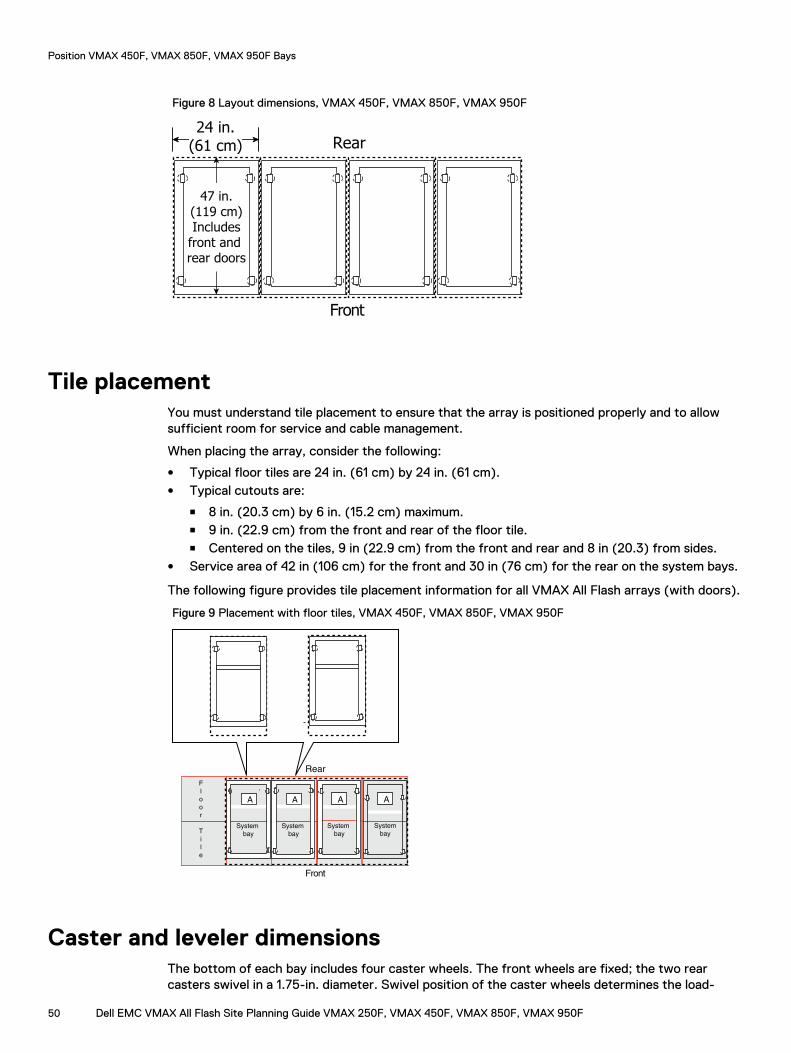
Figure 8 Layout dimensions, VMAX 450F, VMAX 850F, VMAX 950F
Front
Rear
47 in.(119 cm)Includes
front and rear doors
24.02 in.(61.01 cm)
24 in.(61 cm)
Tile placementYou must understand tile placement to ensure that the array is positioned properly and to allowsufficient room for service and cable management.
When placing the array, consider the following:
l Typical floor tiles are 24 in. (61 cm) by 24 in. (61 cm).l Typical cutouts are:
n 8 in. (20.3 cm) by 6 in. (15.2 cm) maximum.n 9 in. (22.9 cm) from the front and rear of the floor tile.n Centered on the tiles, 9 in (22.9 cm) from the front and rear and 8 in (20.3) from sides.
l Service area of 42 in (106 cm) for the front and 30 in (76 cm) for the rear on the system bays.
The following figure provides tile placement information for all VMAX All Flash arrays (with doors).
Figure 9 Placement with floor tiles, VMAX 450F, VMAX 850F, VMAX 950F
Rear
A A
System
bay
System
bay
A
System
bay
A
System
bay
Front
F
l
o
o
r
T
i
l
e
Caster and leveler dimensionsThe bottom of each bay includes four caster wheels. The front wheels are fixed; the two rearcasters swivel in a 1.75-in. diameter. Swivel position of the caster wheels determines the load-
Position VMAX 450F, VMAX 850F, VMAX 950F Bays
50 Dell EMC VMAX All Flash Site Planning Guide VMAX 250F, VMAX 450F, VMAX 850F, VMAX 950F
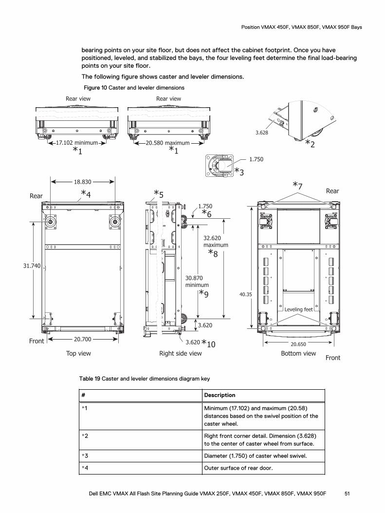
bearing points on your site floor, but does not affect the cabinet footprint. Once you havepositioned, leveled, and stabilized the bays, the four leveling feet determine the final load-bearingpoints on your site floor.
The following figure shows caster and leveler dimensions.
Figure 10 Caster and leveler dimensions
Front
Rear
Front
Rear
18.830
20.700
31.740
*117.102 minimum 20.580 maximum
Top view
Rear view Rear view
Right side view
3.628
3.620
30.870 minimum
32.620 maximum
1.750
1.750
20.650
40.35
Bottom view
Leveling feet
*1*2
*3
3.620
*4*7
*5
*6
*8
*9
*10
Table 19 Caster and leveler dimensions diagram key
# Description
*1 Minimum (17.102) and maximum (20.58)distances based on the swivel position of thecaster wheel.
*2 Right front corner detail. Dimension (3.628)to the center of caster wheel from surface.
*3 Diameter (1.750) of caster wheel swivel.
*4 Outer surface of rear door.
Position VMAX 450F, VMAX 850F, VMAX 950F Bays
Dell EMC VMAX All Flash Site Planning Guide VMAX 250F, VMAX 450F, VMAX 850F, VMAX 950F 51
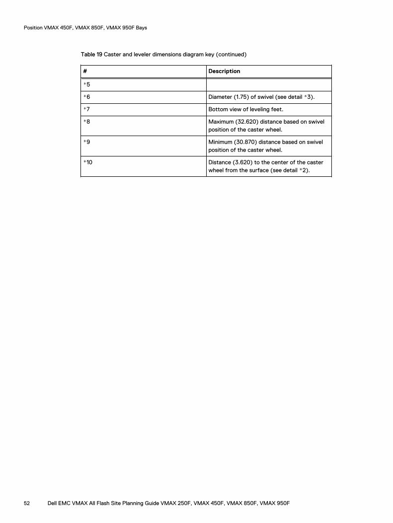
Table 19 Caster and leveler dimensions diagram key (continued)
# Description
*5
*6 Diameter (1.75) of swivel (see detail *3).
*7 Bottom view of leveling feet.
*8 Maximum (32.620) distance based on swivelposition of the caster wheel.
*9 Minimum (30.870) distance based on swivelposition of the caster wheel.
*10 Distance (3.620) to the center of the casterwheel from the surface (see detail *2).
Position VMAX 450F, VMAX 850F, VMAX 950F Bays
52 Dell EMC VMAX All Flash Site Planning Guide VMAX 250F, VMAX 450F, VMAX 850F, VMAX 950F
CHAPTER 8
Power cabling, cords and connectors
This chapter includes:
l Power distribution equipment, VMAX 250F...........................................................................54l Power distribution unit VMAX 450F, VMAX 850F, VMAX 950F............................................56l Wiring configurations, VMAX 250F....................................................................................... 58l Wiring configurations, VMAX 450F, VMAX 850F, VMAX 950F............................................. 62l Power interface.....................................................................................................................65l Customer input power cabling...............................................................................................65l Best practices: Power configuration guidelines..................................................................... 66l Power extension cords, connectors and wiring......................................................................67
Dell EMC VMAX All Flash Site Planning Guide VMAX 250F, VMAX 450F, VMAX 850F, VMAX 950F 53
Power distribution equipment, VMAX 250FThe VMAX 250F is powered by two redundant sets of power distribution equipment, one set foreach power zone. Each set of power distribution equipment consists of a power distribution panel(PDP) and a power distribution unit (PDU).
The PDP is available in three wiring configurations:
l Single-phase
l Three-phase Delta
l Three-phase Wye
Note: The PDP AC power cords (single-phase and three-phase) extend approximately 10"(25cm) above the bay egress for connection to the customer power supply. 15ft (4.57m)extension cables are provided.
Each PDU provides the following:
l A total of 12 power outlets for field replaceable units (FRUs). The outlets are divided into threebanks with each bank consisting of four IEC 60320 C13 individual AC outlets.
l Each bank of outlets is connected to individual branch circuits that are protected by a singletwo pole 20 Amp circuit breaker.
l PDP input connectors differ depending on the customer input power.
If the customer requires power to be supplied from overhead, the Overhead routing kit is availableto route the power cables inside the machine through the top.
Power cabling, cords and connectors
54 Dell EMC VMAX All Flash Site Planning Guide VMAX 250F, VMAX 450F, VMAX 850F, VMAX 950F
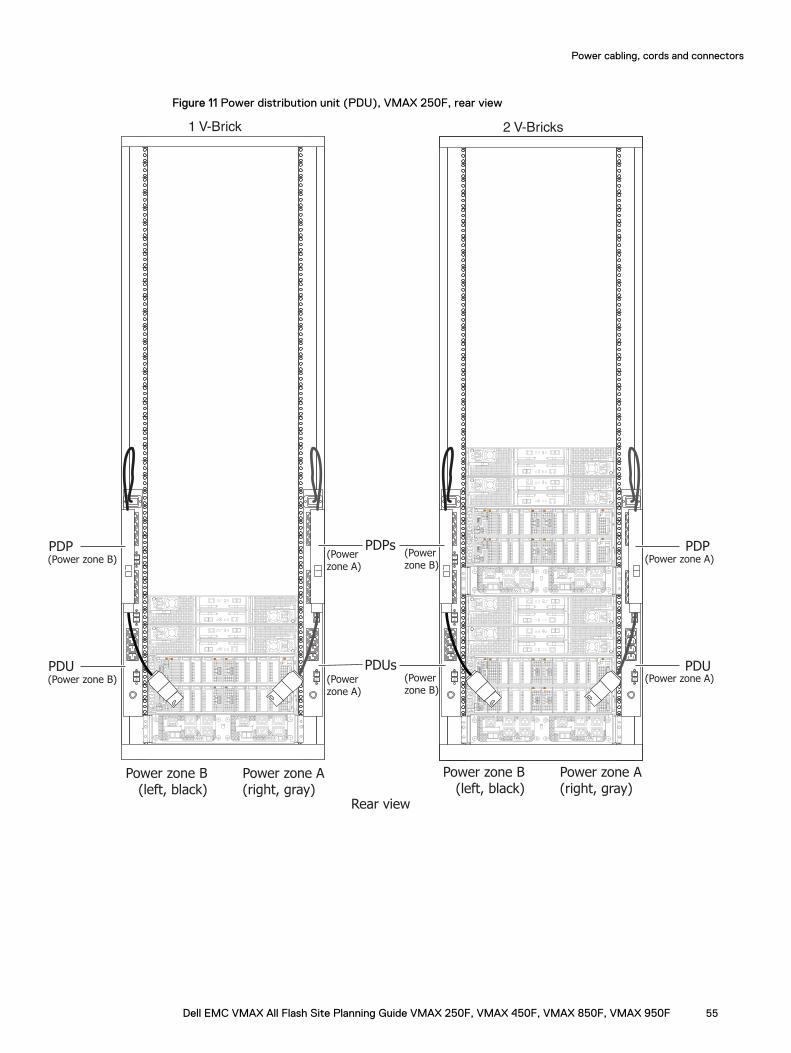
Figure 11 Power distribution unit (PDU), VMAX 250F, rear view
Rear view
2 V-Bricks
PDPs
10
10
A
B
10
10
A
B
1 V-Brick
10
10
A
BON
I
OFF
O
ON
I
OFF
O
ON
I
OFF
O
ON
I
OFF
O
ON
I
OFF
O
ON
I
OFF
O
ON
I
OFF
O
ON
I
OFF
O
ON
I
OFF
O
ON
I
OFF
O
ON
I
OFF
O
ON
I
OFF
O
PDUs
PDP
PDU
PDP
PDU
Power zone A(right, gray)
Power zone B(left, black)
Power zone A(right, gray)
Power zone B(left, black)
(Power zone B)
(Power zone B)
(Power zone B)
(Power zone A)
(Power zone B)
(Power zone A)
(Power zone A)
(Power zone A)
Power cabling, cords and connectors
Dell EMC VMAX All Flash Site Planning Guide VMAX 250F, VMAX 450F, VMAX 850F, VMAX 950F 55
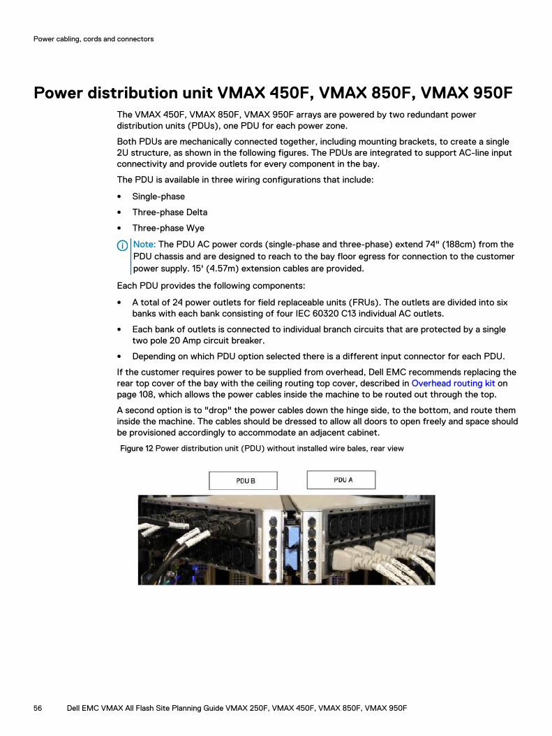
Power distribution unit VMAX 450F, VMAX 850F, VMAX 950FThe VMAX 450F, VMAX 850F, VMAX 950F arrays are powered by two redundant powerdistribution units (PDUs), one PDU for each power zone.
Both PDUs are mechanically connected together, including mounting brackets, to create a single2U structure, as shown in the following figures. The PDUs are integrated to support AC-line inputconnectivity and provide outlets for every component in the bay.
The PDU is available in three wiring configurations that include:
l Single-phase
l Three-phase Delta
l Three-phase Wye
Note: The PDU AC power cords (single-phase and three-phase) extend 74" (188cm) from thePDU chassis and are designed to reach to the bay floor egress for connection to the customerpower supply. 15' (4.57m) extension cables are provided.
Each PDU provides the following components:
l A total of 24 power outlets for field replaceable units (FRUs). The outlets are divided into sixbanks with each bank consisting of four IEC 60320 C13 individual AC outlets.
l Each bank of outlets is connected to individual branch circuits that are protected by a singletwo pole 20 Amp circuit breaker.
l Depending on which PDU option selected there is a different input connector for each PDU.
If the customer requires power to be supplied from overhead, Dell EMC recommends replacing therear top cover of the bay with the ceiling routing top cover, described in Overhead routing kit onpage 108, which allows the power cables inside the machine to be routed out through the top.
A second option is to "drop" the power cables down the hinge side, to the bottom, and route theminside the machine. The cables should be dressed to allow all doors to open freely and space shouldbe provisioned accordingly to accommodate an adjacent cabinet.
Figure 12 Power distribution unit (PDU) without installed wire bales, rear view
Power cabling, cords and connectors
56 Dell EMC VMAX All Flash Site Planning Guide VMAX 250F, VMAX 450F, VMAX 850F, VMAX 950F
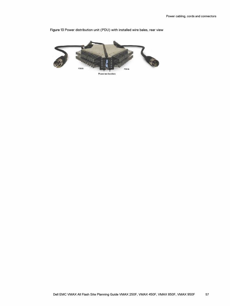
Figure 13 Power distribution unit (PDU) with installed wire bales, rear view
Power cabling, cords and connectors
Dell EMC VMAX All Flash Site Planning Guide VMAX 250F, VMAX 450F, VMAX 850F, VMAX 950F 57
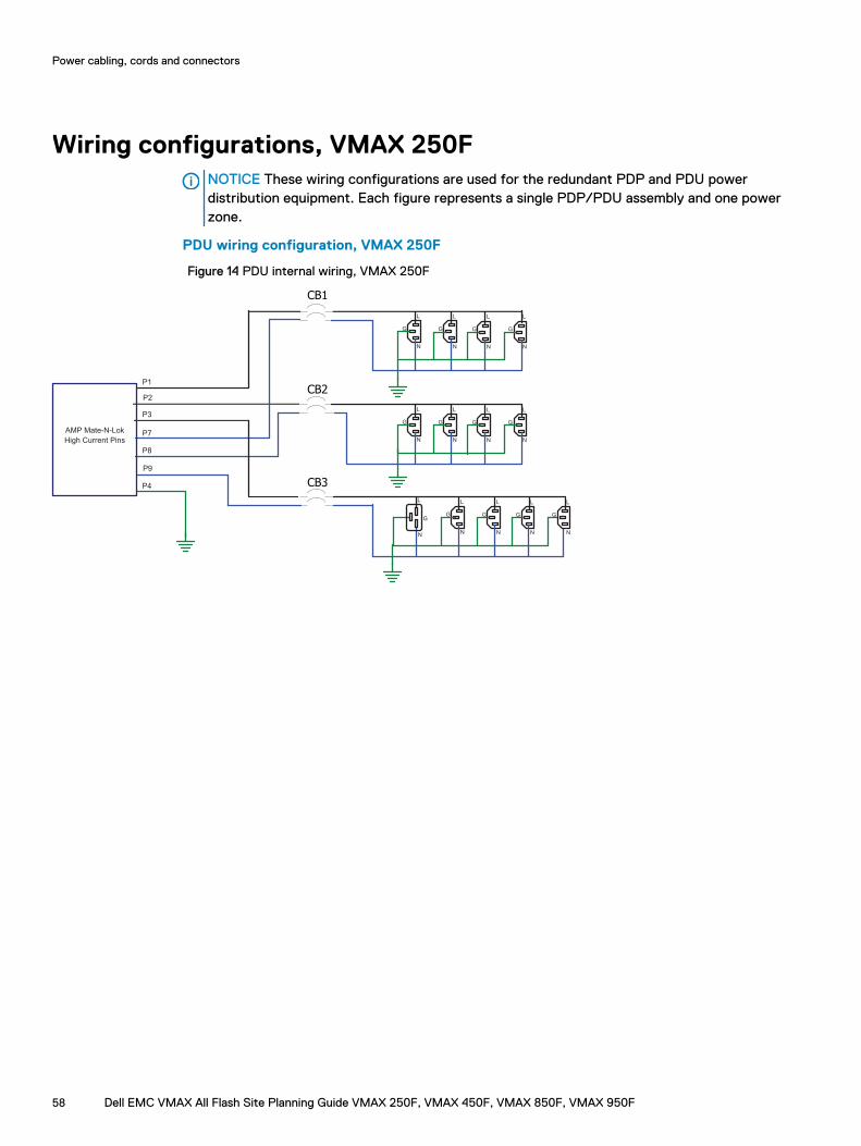
Wiring configurations, VMAX 250FNOTICE These wiring configurations are used for the redundant PDP and PDU powerdistribution equipment. Each figure represents a single PDP/PDU assembly and one powerzone.
PDU wiring configuration, VMAX 250F
Figure 14 PDU internal wiring, VMAX 250F
L
N
G
L
N
G
L
N
G
L
N
G
L
N
G
L
N
G
L
N
G
L
N
G
L
N
G
L
N
G
L
N
G
L
N
G
AMP Mate-N-Lok
High Current Pins
L
N
G
P1
P4
P3
P8
P9
P7
P2
CB1
CB2
CB3
Power cabling, cords and connectors
58 Dell EMC VMAX All Flash Site Planning Guide VMAX 250F, VMAX 450F, VMAX 850F, VMAX 950F
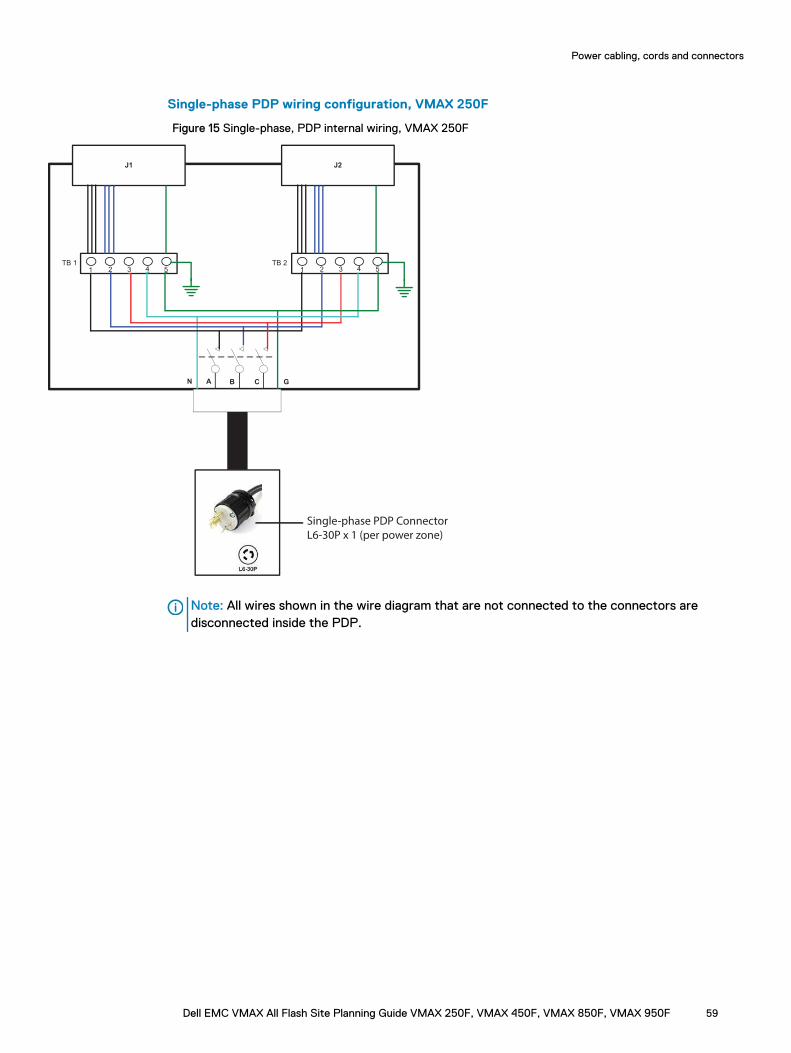
Single-phase PDP wiring configuration, VMAX 250F
Figure 15 Single-phase, PDP internal wiring, VMAX 250F
J1 J2
B CAN G
TB 1 TB 2
1 2 3 4 5 1 2 3 4 5
Single-phase PDP Connector
L6-30P x 1 (per power zone)
Note: All wires shown in the wire diagram that are not connected to the connectors aredisconnected inside the PDP.
Power cabling, cords and connectors
Dell EMC VMAX All Flash Site Planning Guide VMAX 250F, VMAX 450F, VMAX 850F, VMAX 950F 59
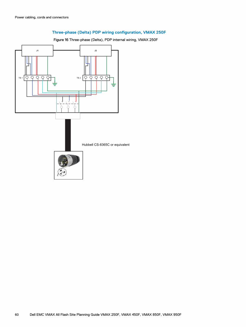
Three-phase (Delta) PDP wiring configuration, VMAX 250F
Figure 16 Three-phase (Delta), PDP internal wiring, VMAX 250F
J1 J2
1 2 3 4 5TB 2
1 2 3 4 5TB 1
Hubbell CS-8365C or equivalent
Power cabling, cords and connectors
60 Dell EMC VMAX All Flash Site Planning Guide VMAX 250F, VMAX 450F, VMAX 850F, VMAX 950F
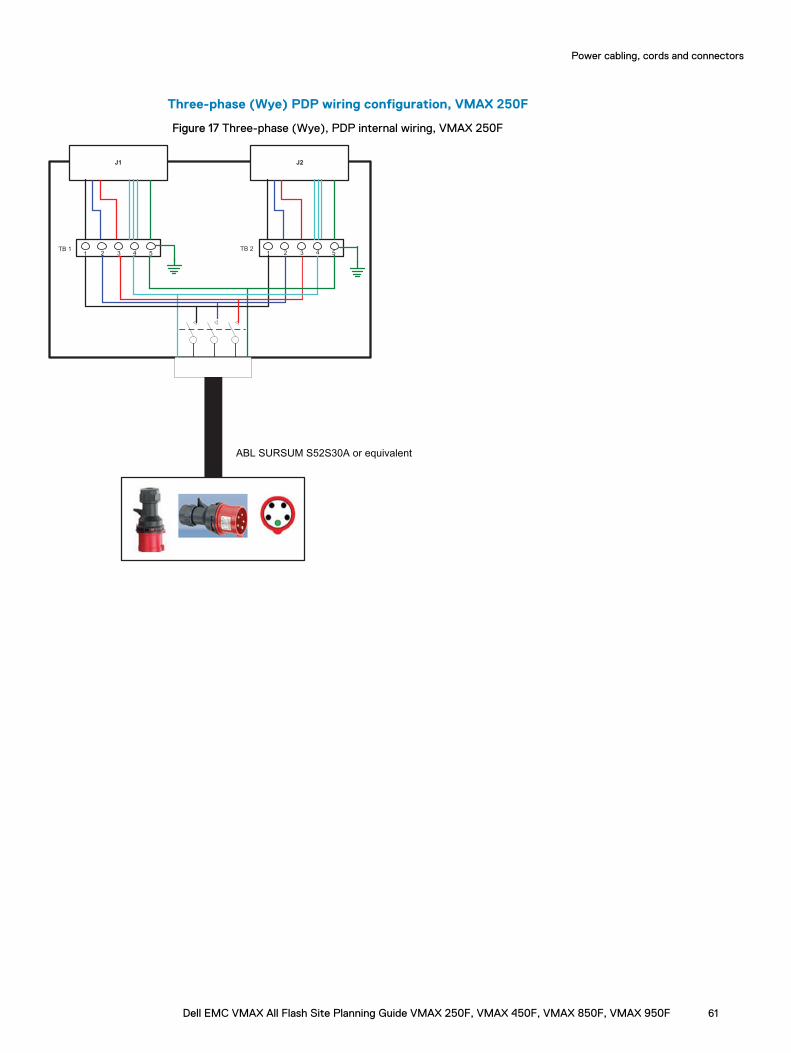
Three-phase (Wye) PDP wiring configuration, VMAX 250F
Figure 17 Three-phase (Wye), PDP internal wiring, VMAX 250F
J1 J2
1 2 3 4 5TB 2
1 2 3 4 5TB 1
ABL SURSUM S52S30A or equivalent
Power cabling, cords and connectors
Dell EMC VMAX All Flash Site Planning Guide VMAX 250F, VMAX 450F, VMAX 850F, VMAX 950F 61
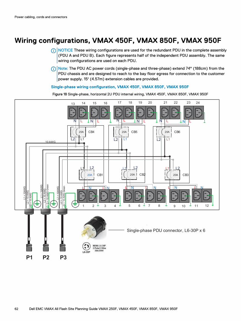
Wiring configurations, VMAX 450F, VMAX 850F, VMAX 950FNOTICE These wiring configurations are used for the redundant PDU in the complete assembly(PDU A and PDU B). Each figure represents half of the independent PDU assembly. The samewiring configurations are used on each PDU.
Note: The PDU AC power cords (single-phase and three-phase) extend 74" (188cm) from thePDU chassis and are designed to reach to the bay floor egress for connection to the customerpower supply. 15' (4.57m) extension cables are provided.
Single-phase wiring configuration, VMAX 450F, VMAX 850F, VMAX 950F
Figure 18 Single-phase, horizontal 2U PDU internal wiring, VMAX 450F, VMAX 850F, VMAX 950F
1 2 3
1514 16 18 19 2120
20A CB4
22
20A CB1
20A CB5 20A CB6
23
20A CB2 20A CB3
L1
L1
L1
L1 L1
L1
4 5 6 7 8 9 10 11
13
LN LN LN
L1
= 1
0A
WG
L2
= 1
0 A
WG
10 AWG
NL L N L N
P1
L2
L2 L2
L2
L2
L2
G
G =
10
AW
G
G
L1
= 1
0A
WG
L2
= 1
0 A
WG
G =
10
AW
G G
reen
L1
= 1
0A
WG
L2
= 1
0 A
WG
G =
10
AW
G G
reen
G
P2 P3
.
LN LN
17
NL L N L N
LN
12
24
P3P1 P2
Single-phase PDU connector, L6-30P x 6
Power cabling, cords and connectors
62 Dell EMC VMAX All Flash Site Planning Guide VMAX 250F, VMAX 450F, VMAX 850F, VMAX 950F
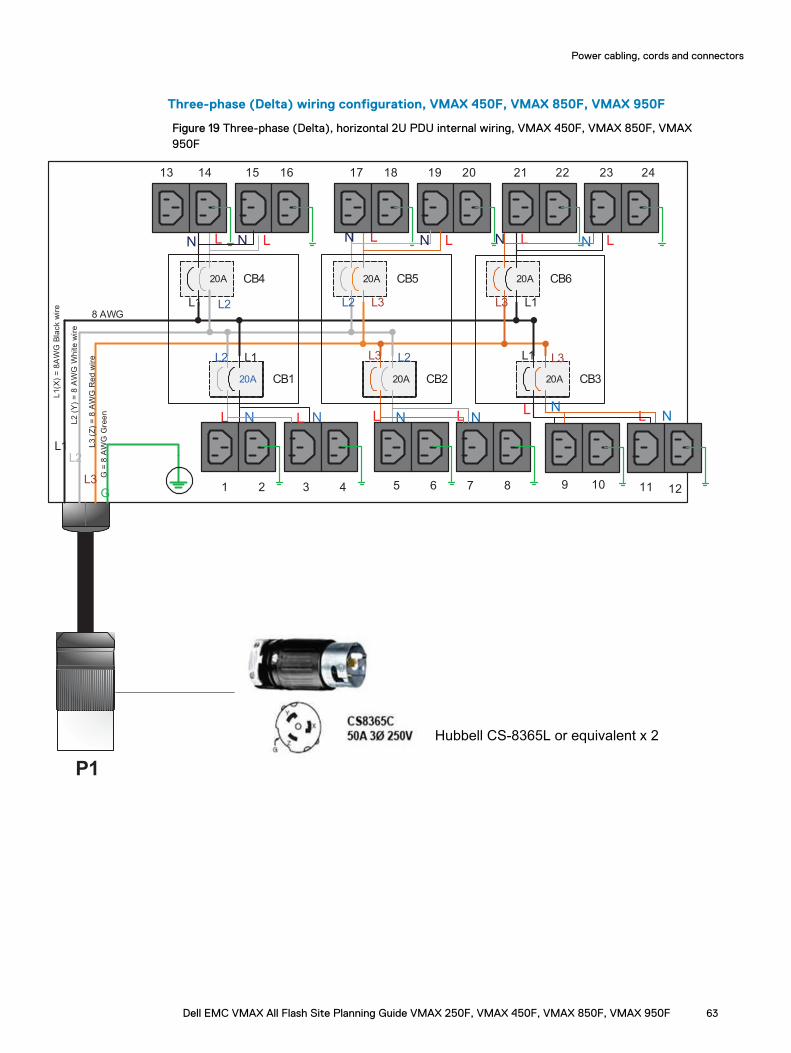
Three-phase (Delta) wiring configuration, VMAX 450F, VMAX 850F, VMAX 950F
Figure 19 Three-phase (Delta), horizontal 2U PDU internal wiring, VMAX 450F, VMAX 850F, VMAX950F
20A CB4
20A CB1
20A CB5 20A CB6
L1L2
L3G
20A CB2 20A CB3
L1
L1
L1
L1L2
L2
L2
L2 L3
L3 L3
L3
L1(X
) =
8A
WG
Bla
ck
wir
e
L2
(Y
) =
8 A
WG
White
wir
e
L3
(Z
) =
8 A
WG
Re
d w
ire
G =
8 A
WG
Gre
en
8 AWG
P1
1413 15 17 18 2019 21 22
12
LN LN LNLN LN
16
LN
1 2 3 4 5 6 7 8 9 10 11
NL L NL N
NL L N L N
23 24
Hubbell CS-8365L or equivalent x 2
Power cabling, cords and connectors
Dell EMC VMAX All Flash Site Planning Guide VMAX 250F, VMAX 450F, VMAX 850F, VMAX 950F 63
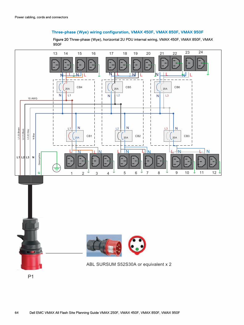
Three-phase (Wye) wiring configuration, VMAX 450F, VMAX 850F, VMAX 950F
Figure 20 Three-phase (Wye), horizontal 2U PDU internal wiring, VMAX 450F, VMAX 850F, VMAX950F
P1
20ACB4
20ACB1
20ACB5
20ACB6
L1 L2 L3 N
20ACB2
20ACB3
L1
L1
L2
L2 L3
L3
L1
(X
) B
row
n
L2
(Y
) B
lack
L3
(Z
) G
ray
Gre
en/y
ello
w
10 AWG
G
N
N N
N
N
N
N B
lue
1413 15 17 18 2019 21 22
12
LN LN LNLN LN
16
LN
1 2 3 4 5 6 7 8 9 10 11
NL L N L NNL L N L N
23 24
ABL SURSUM S52S30A or equivalent x 2
Power cabling, cords and connectors
64 Dell EMC VMAX All Flash Site Planning Guide VMAX 250F, VMAX 450F, VMAX 850F, VMAX 950F
Power interfaceData centers must conform to the corresponding specification for arrays installed in NorthAmerican, International, and Australian sites.
VMAX 250F
Each system contains a complete set of power distribution equipment.
VMAX 450F, VMAX 850F, VMAX 950F
Each bay in a system configuration contains a complete 2U PDU assembly. The PDU assembly isconstructed with two electrically individual PDUs.
NOTICE Customers are responsible for meeting all local electrical safety requirements.
Customer input power cablingBefore the array is delivered, the customer must supply and install the required receptacles ontheir PDUs for zone A and zone B power for each system bay.
Dell EMC recommends that the customer's electrician be present at installation time to work withthe Dell EMC customer engineer to verify power redundancy.
Refer to the Dell EMC Best Practices Guide for AC Power Connections for PowerMax 2000, 8000 withPowerMaxOS for required items at the customer site.
Power cabling, cords and connectors
Dell EMC VMAX All Flash Site Planning Guide VMAX 250F, VMAX 450F, VMAX 850F, VMAX 950F 65
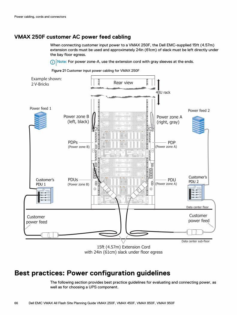
VMAX 250F customer AC power feed cablingWhen connecting customer input power to a VMAX 250F, the Dell EMC-supplied 15ft (4.57m)extension cords must be used and approximately 24in (61cm) of slack must be left directly underthe bay floor egress.
Note: For power zone-A, use the extension cord with gray sleeves at the ends.
Figure 21 Customer input power cabling for VMAX 250F
Rear viewExample shown:
2 V-Bricks
PDPs
Customer’sPDU 2
Power feed 2
Customer’sPDU 1
Circuit breakers - Numbers
27
28
29
30
...
Circuit breakers - Numbers
27
28
29
30
...
Power feed 1
10
10
A
B
10
10
A
B
ON
I
OFF
O
ON
I
OFF
O
ON
I
OFF
O
ON
I
OFF
O
ON
I
OFF
O
ON
I
OFF
O
15ft (4.57m) Extension Cordwith 24in (61cm) slack under floor egress
Customer power feed
Customer power feed
PDUs
40U rack
PDP
PDU
Power zone A(right, gray)
Power zone B(left, black)
(Power zone B)
(Power zone B) (Power zone A)
(Power zone A)
Data center sub-floor
Data center floor
Best practices: Power configuration guidelinesThe following section provides best practice guidelines for evaluating and connecting power, aswell as for choosing a UPS component.
Power cabling, cords and connectors
66 Dell EMC VMAX All Flash Site Planning Guide VMAX 250F, VMAX 450F, VMAX 850F, VMAX 950F

Uptime Institute best practices
Follow these best practice guidelines when connecting AC power to the array:
l The Dell EMC customer engineer (CE) should discuss with the customer the need forvalidating AC power redundancy at each bay. If the power redundancy requirements are notmet in each bay, a Data Unavailable (DU) event could occur.
l The customer should complete power provisioning with the data center prior to connectingpower to the array.
l The customer‘s electrician or facilities representative must verify that the AC voltage is withinspecification at each of the power drops being fed to each product bay.
l All of the power drops should be labeled to indicate the source of power (PDU) and thespecific circuit breakers utilized within each PDU:
n Color code the power cables to help achieve redundancy.
n Clearly label the equipment served by each circuit breaker within the customer PDU.
l The electrician or facilities representative must verify that there are two power drops fed fromseparate redundant PDUs prior to turning on the array:
n If both power drops to a bay are connected to the same PDU incorrectly, a DU event willresult during normal data center maintenance when the PDU is switched off. The label onthe power cables depicts the correct connection.
l The electrician should pay particular attention to how each PDU receives power from eachUPS within the data center because it is possible to create a scenario where turning off a UPSfor maintenance could cause both power feeds to a single bay to be turned off, creating a DUevent.
l The customer’s electrician should perform an AC verification test by turning off the individualcircuit breakers feeding each power zone within the bay, while the customer engineer monitorsthe LED on the SPS modules to verify that power redundancy has been achieved in each bay.
One customer PDU should never supply both power zone feeds to any one rack of equipment.
Power extension cords, connectors and wiringThe following section illustrates a variety of extension cords that offer different interfaceconnector options. The selected cords are used to interface between the customer’s power sourceand each PDU connection.
The number of cords needed is determined by the number of bays in the array and the type ofinput power source used (single-phase or three-phase).
Power cabling, cords and connectors
Dell EMC VMAX All Flash Site Planning Guide VMAX 250F, VMAX 450F, VMAX 850F, VMAX 950F 67
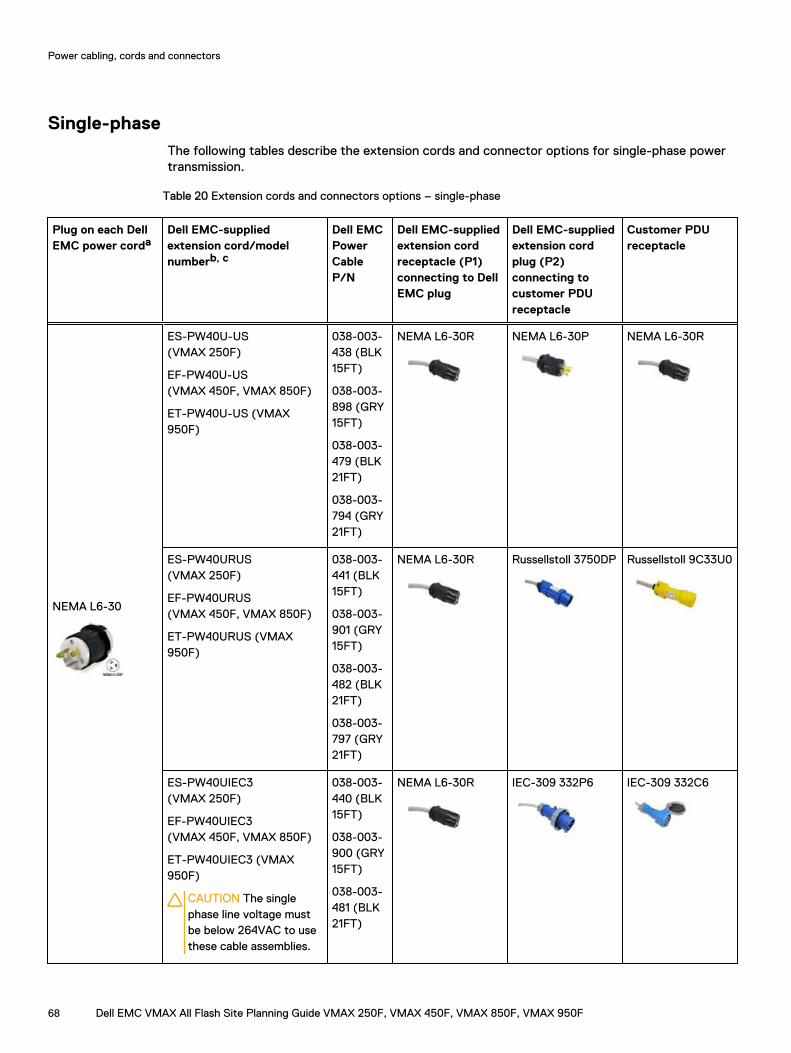
Single-phaseThe following tables describe the extension cords and connector options for single-phase powertransmission.
Table 20 Extension cords and connectors options – single-phase
Plug on each DellEMC power corda
Dell EMC-suppliedextension cord/modelnumberb, c
Dell EMCPowerCableP/N
Dell EMC-suppliedextension cordreceptacle (P1)connecting to DellEMC plug
Dell EMC-suppliedextension cordplug (P2)connecting tocustomer PDUreceptacle
Customer PDUreceptacle
NEMA L6-30
ES-PW40U-US(VMAX 250F)
EF-PW40U-US(VMAX 450F, VMAX 850F)
ET-PW40U-US (VMAX950F)
038-003-438 (BLK15FT)
038-003-898 (GRY15FT)
038-003-479 (BLK21FT)
038-003-794 (GRY21FT)
NEMA L6-30R NEMA L6-30P NEMA L6-30R
ES-PW40URUS(VMAX 250F)
EF-PW40URUS(VMAX 450F, VMAX 850F)
ET-PW40URUS (VMAX950F)
038-003-441 (BLK15FT)
038-003-901 (GRY15FT)
038-003-482 (BLK21FT)
038-003-797 (GRY21FT)
NEMA L6-30R Russellstoll 3750DP Russellstoll 9C33U0
ES-PW40UIEC3(VMAX 250F)
EF-PW40UIEC3(VMAX 450F, VMAX 850F)
ET-PW40UIEC3 (VMAX950F)
CAUTION The singlephase line voltage mustbe below 264VAC to usethese cable assemblies.
038-003-440 (BLK15FT)
038-003-900 (GRY15FT)
038-003-481 (BLK21FT)
NEMA L6-30R IEC-309 332P6 IEC-309 332C6
Power cabling, cords and connectors
68 Dell EMC VMAX All Flash Site Planning Guide VMAX 250F, VMAX 450F, VMAX 850F, VMAX 950F
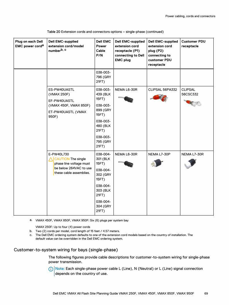
Table 20 Extension cords and connectors options – single-phase (continued)
Plug on each DellEMC power corda
Dell EMC-suppliedextension cord/modelnumberb, c
Dell EMCPowerCableP/N
Dell EMC-suppliedextension cordreceptacle (P1)connecting to DellEMC plug
Dell EMC-suppliedextension cordplug (P2)connecting tocustomer PDUreceptacle
Customer PDUreceptacle
038-003-796 (GRY21FT)
ES-PW40UASTL(VMAX 250F)
EF-PW40UASTL(VMAX 450F, VMAX 850F)
ET-PW40UASTL (VMAX950F)
038-003-439 (BLK15FT)
038-003-899 (GRY15FT)
038-003-480 (BLK21FT)
038-003-795 (GRY21FT)
NEMA L6-30R CLIPSAL 56PA332 CLIPSAL56CSC332
E-PW40L730CAUTION The singlephase line voltage mustbe below 264VAC to usethese cable assemblies.
038-004-301 (BLK15FT)
038-004-302 (GRY15FT)
038-004-303 (BLK21FT)
038-004-304 (GRY21FT)
NEMA L6-30R NEMA L7-30P NEMA L7-30R
a. VMAX 450F, VMAX 850F, VMAX 950F: Six (6) plugs per system bay
VMAX 250F: Up to four (4) power cordsb. Two (2) cords per model, cord length of 15 feet / 4.57 meters.c. The Dell EMC ordering system defaults to one of the extension cord models based on the country of installation. The
default value can be overridden in the Dell EMC ordering system.
Customer-to-system wiring for bays (single-phase)
The following figures provide cable descriptions for customer-to-system wiring for single-phasepower transmission.
Note: Each single-phase power cable L (Line), N (Neutral) or L (Line) signal connectiondepends on the country of use.
Power cabling, cords and connectors
Dell EMC VMAX All Flash Site Planning Guide VMAX 250F, VMAX 450F, VMAX 850F, VMAX 950F 69
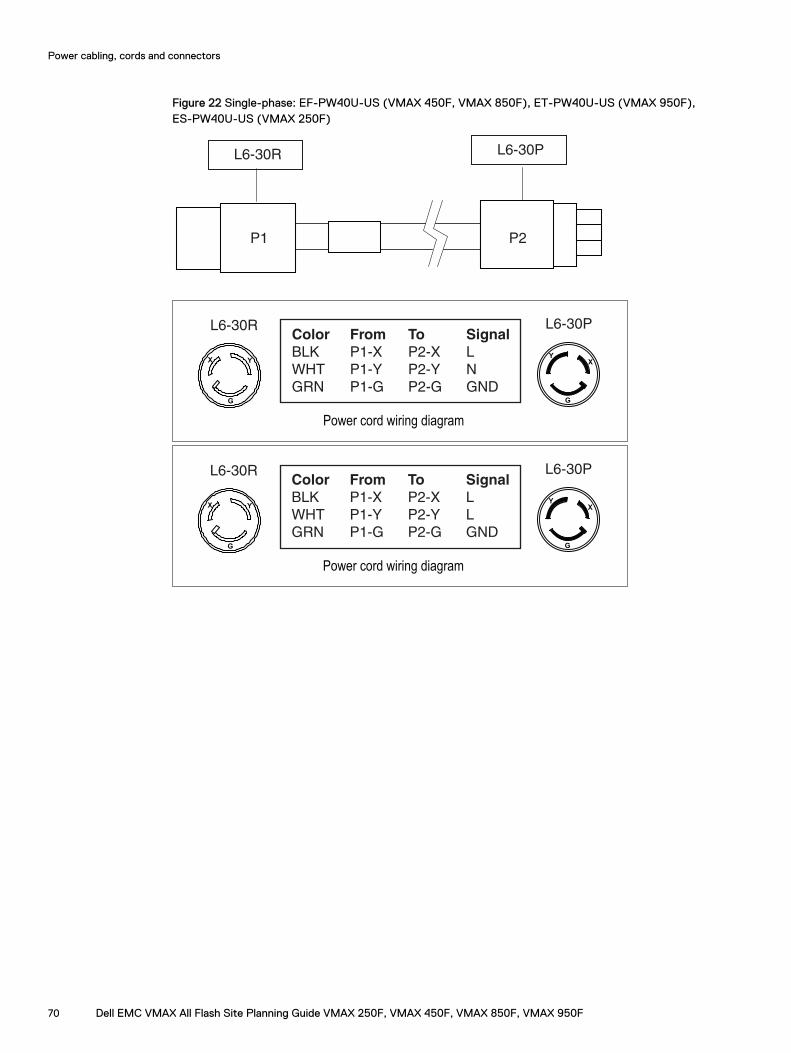
Figure 22 Single-phase: EF-PW40U-US (VMAX 450F, VMAX 850F), ET-PW40U-US (VMAX 950F),ES-PW40U-US (VMAX 250F)
P1 P2
L6-30R L6-30P
X Y
G
Power cord wiring diagram
Color From To Signal
BLK P1-X P2-X L
WHT P1-Y P2-Y N
GRN P1-G P2-G GND
XY
G
L6-30R L6-30P
X Y
G
Power cord wiring diagram
Color From To Signal
BLK P1-X P2-X L
WHT P1-Y P2-Y L
GRN P1-G P2-G GND
XY
G
L6-30R L6-30P
Power cabling, cords and connectors
70 Dell EMC VMAX All Flash Site Planning Guide VMAX 250F, VMAX 450F, VMAX 850F, VMAX 950F
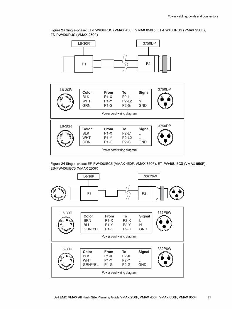
Figure 23 Single-phase: EF-PW40URUS (VMAX 450F, VMAX 850F), ET-PW40URUS (VMAX 950F),ES-PW40URUS (VMAX 250F)
P1 P2
L6-30R 3750DP
X Y
G
Color From To Signal
BLK P1-X P2-L1 L
WHT P1-Y P2-L2 N
GRN P1-G P2-G GND
Power cord wiring diagram
L6-30R
L1 L2
G
3750DP
X Y
G
Color From To Signal
BLK P1-X P2-L1 L
WHT P1-Y P2-L2 L
GRN P1-G P2-G GND
Power cord wiring diagram
L6-30R
L1 L2
G
3750DP
Figure 24 Single-phase: EF-PW40UIEC3 (VMAX 450F, VMAX 850F), ET-PW40UIEC3 (VMAX 950F),ES-PW40UIEC3 (VMAX 250F)
X Y
G
P1 P2
L6-30R 332P6W
G
Y X
Color From To Signal
BRN P1-X P2-X L
BLU P1-Y P2-Y N
GRN/YEL P1-G P2-G GND
X Y
G
Power cord wiring diagram
L6-30R 332P6W
X Y
G
Color From To Signal
BLK P1-X P2-X L
WHT P1-Y P2-Y L
GRN/YEL P1-G P2-G GND
Power cord wiring diagram
L6-30R 332P6W
G
Y X
G
Y X
Power cabling, cords and connectors
Dell EMC VMAX All Flash Site Planning Guide VMAX 250F, VMAX 450F, VMAX 850F, VMAX 950F 71
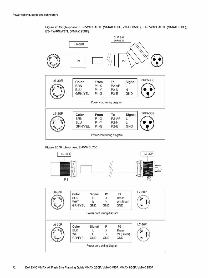
Figure 25 Single-phase: EF-PW40UASTL (VMAX 450F, VMAX 850F), ET-PW40UASTL (VMAX 950F),ES-PW40UASTL (VMAX 250F)
P1 P2
L6-30R
CLIPSAL
56PA332
Color From To Signal
BRN P1-X P2-AP L
BLU P1-Y P2-N N
GRN/YEL P1-G P2-E GND
X Y
G
Power cord wiring diagram
L6-30R 56PA332
G
Y X
G
Y X
G
Y X
Color From To Signal
BRN P1-X P2-AP L
BLU P1-Y P2-N L
GRN/YEL P1-G P2-E GND
X Y
G
Power cord wiring diagram
L6-30R 56PA332
G
Y X
G
Y X
X Y
G
Figure 26 Single-phase: E-PW40L730
L6-30R L7-30P
P1 P2
Color Signal P1 P2
BLK L X Brass
WHT N Y W (Silver)
GRN/YEL GND GND GND
X Y
G
Power cord wiring diagram
L6-30R L7-30P
Color Signal P1 P2
BLK L X Brass
WHT L Y W (Silver)
GRN/YEL GND GND GND
X Y
G
Power cord wiring diagram
L6-30R L7-30P
Power cabling, cords and connectors
72 Dell EMC VMAX All Flash Site Planning Guide VMAX 250F, VMAX 450F, VMAX 850F, VMAX 950F
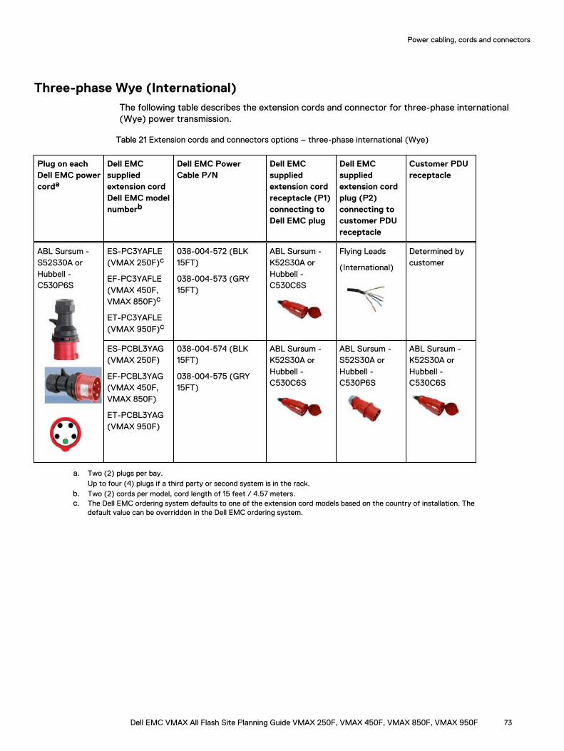
Three-phase Wye (International)The following table describes the extension cords and connector for three-phase international(Wye) power transmission.
Table 21 Extension cords and connectors options – three-phase international (Wye)
Plug on eachDell EMC powercorda
Dell EMCsuppliedextension cordDell EMC modelnumberb
Dell EMC PowerCable P/N
Dell EMCsuppliedextension cordreceptacle (P1)connecting toDell EMC plug
Dell EMCsuppliedextension cordplug (P2)connecting tocustomer PDUreceptacle
Customer PDUreceptacle
ABL Sursum -S52S30A orHubbell -C530P6S
ES-PC3YAFLE(VMAX 250F)c
EF-PC3YAFLE(VMAX 450F,VMAX 850F)c
ET-PC3YAFLE(VMAX 950F)c
038-004-572 (BLK15FT)
038-004-573 (GRY15FT)
ABL Sursum -K52S30A orHubbell -C530C6S
Flying Leads
(International)
Determined bycustomer
ES-PCBL3YAG(VMAX 250F)
EF-PCBL3YAG(VMAX 450F,VMAX 850F)
ET-PCBL3YAG(VMAX 950F)
038-004-574 (BLK15FT)
038-004-575 (GRY15FT)
ABL Sursum -K52S30A orHubbell -C530C6S
ABL Sursum -S52S30A orHubbell -C530P6S
ABL Sursum -K52S30A orHubbell -C530C6S
a. Two (2) plugs per bay.Up to four (4) plugs if a third party or second system is in the rack.
b. Two (2) cords per model, cord length of 15 feet / 4.57 meters.c. The Dell EMC ordering system defaults to one of the extension cord models based on the country of installation. The
default value can be overridden in the Dell EMC ordering system.
Power cabling, cords and connectors
Dell EMC VMAX All Flash Site Planning Guide VMAX 250F, VMAX 450F, VMAX 850F, VMAX 950F 73
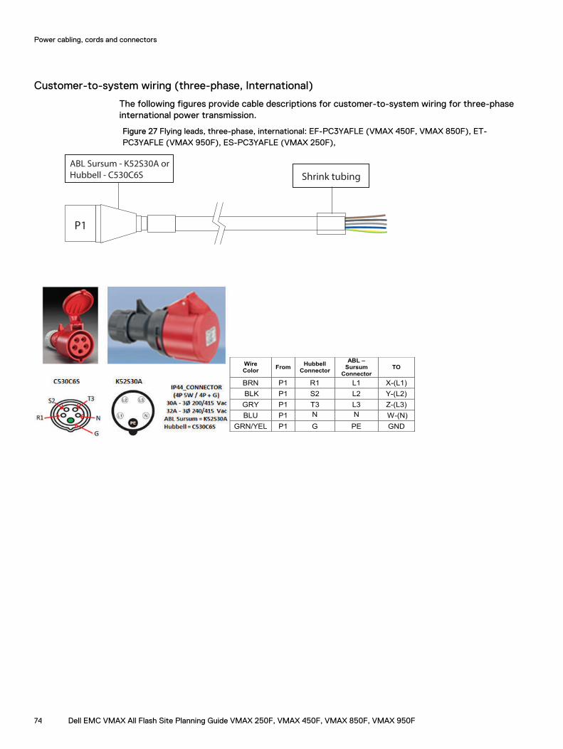
Customer-to-system wiring (three-phase, International)
The following figures provide cable descriptions for customer-to-system wiring for three-phaseinternational power transmission.
Figure 27 Flying leads, three-phase, international: EF-PC3YAFLE (VMAX 450F, VMAX 850F), ET-PC3YAFLE (VMAX 950F), ES-PC3YAFLE (VMAX 250F),
P1
Shrink tubing
ABL Sursum - K52S30A or
Hubbell - C530C6S
Wire
Color From
Hubbell
Connector
ABL –
Sursum
Connector
TO
BRN P1 R1 L1 X-(L1)
BLK P1 S2 L2 Y-(L2)
GRY P1 T3 L3 Z-(L3)
BLU P1 N N W-(N)
GRN/YEL P1 G PE GND
Power cabling, cords and connectors
74 Dell EMC VMAX All Flash Site Planning Guide VMAX 250F, VMAX 450F, VMAX 850F, VMAX 950F
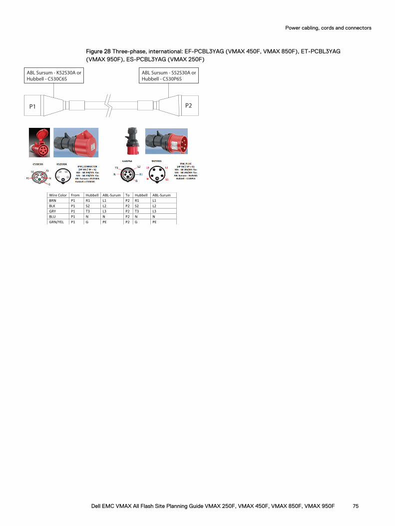
Figure 28 Three-phase, international: EF-PCBL3YAG (VMAX 450F, VMAX 850F), ET-PCBL3YAG(VMAX 950F), ES-PCBL3YAG (VMAX 250F)
P1
ABL Sursum - K52S30A or
Hubbell - C530C6S
P2
ABL Sursum - S52S30A or
Hubbell - C530P6S
Wire Color From Hubbell ABL-Surum To Hubbell ABL-Surum
BRN P1 R1 L1 P2 R1 L1
BLK P1 S2 L2 P2 S2 L2
GRY P1 T3 L3 P2 T3 L3
BLU P1 N N P2 N N
GRN/YEL P1 G PE P2 G PE
Power cabling, cords and connectors
Dell EMC VMAX All Flash Site Planning Guide VMAX 250F, VMAX 450F, VMAX 850F, VMAX 950F 75
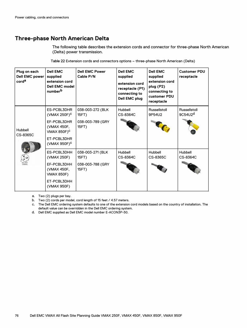
Three-phase North American DeltaThe following table describes the extension cords and connector for three-phase North American(Delta) power transmission.
Table 22 Extension cords and connectors options – three-phase North American (Delta)
Plug on eachDell EMC powercorda
Dell EMCsuppliedextension cordDell EMC modelnumberb
Dell EMC PowerCable P/N
Dell EMCsupplied
extension cordreceptacle (P1)connecting toDell EMC plug
Dell EMCsuppliedextension cordplug (P2)connecting tocustomer PDUreceptacle
Customer PDUreceptacle
HubbellCS-8365C
ES-PCBL3DHR(VMAX 250F)c
EF-PCBL3DHR(VMAX 450F,VMAX 850F)c
ET-PCBL3DHR(VMAX 950F)c
038-003-272 (BLK15FT)
038-003-789 (GRY15FT)
HubbellCS-8364C
Russellstoll9P54U2
Russellstoll9C54U2d
ES-PCBL3DHH(VMAX 250F)
EF-PCBL3DHH(VMAX 450F,VMAX 850F)
ET-PCBL3DHH(VMAX 950F)
038-003-271 (BLK15FT)
038-003-788 (GRY15FT)
HubbellCS-8364C
HubbellCS-8365C
HubbellCS-8364C
a. Two (2) plugs per bay.b. Two (2) cords per model, cord length of 15 feet / 4.57 meters.c. The Dell EMC ordering system defaults to one of the extension cord models based on the country of installation. The
default value can be overridden in the Dell EMC ordering system.d. Dell EMC supplied as Dell EMC model number E-ACON3P-50.
Power cabling, cords and connectors
76 Dell EMC VMAX All Flash Site Planning Guide VMAX 250F, VMAX 450F, VMAX 850F, VMAX 950F
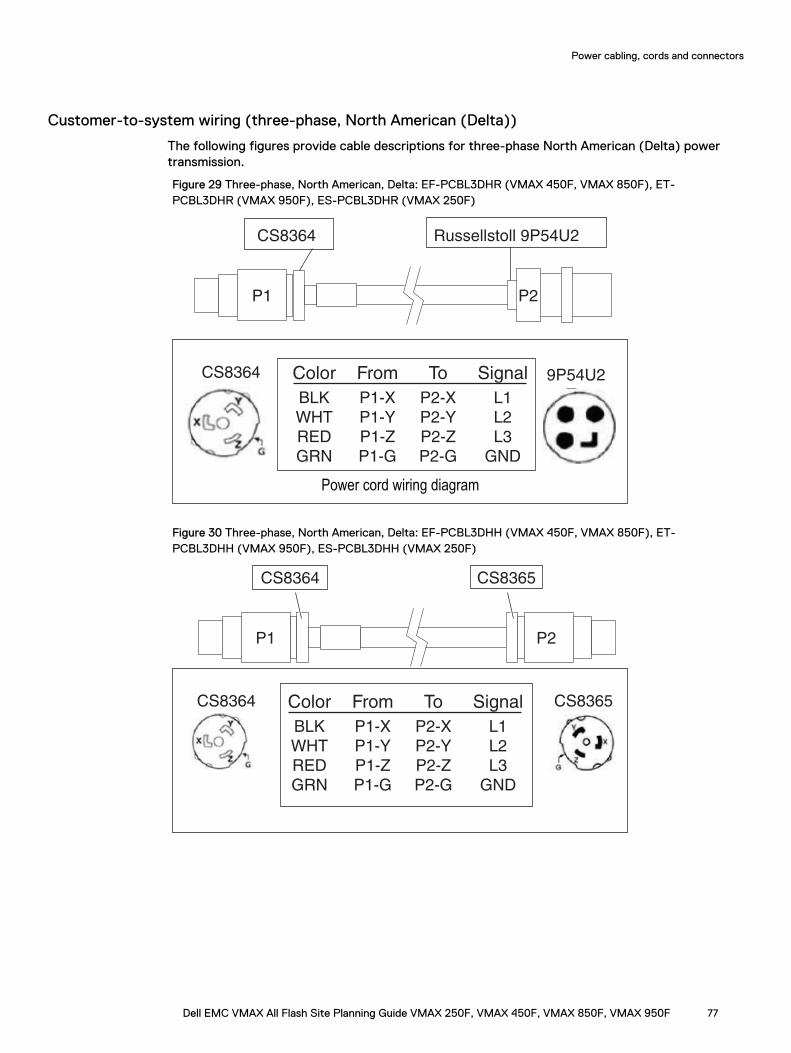
Customer-to-system wiring (three-phase, North American (Delta))
The following figures provide cable descriptions for three-phase North American (Delta) powertransmission.
Figure 29 Three-phase, North American, Delta: EF-PCBL3DHR (VMAX 450F, VMAX 850F), ET-PCBL3DHR (VMAX 950F), ES-PCBL3DHR (VMAX 250F)
P1 P2
CS8364 Russellstoll 9P54U2
CS8364 9P54U2Color
BLK
WHT
RED
GRN
From
P1-X
P1-Y
P1-Z
P1-G
To
P2-X
P2-Y
P2-Z
P2-G
Signal
L1
L2
L3
GND
X
YZX
Y
Z
Power cord wiring diagram
Figure 30 Three-phase, North American, Delta: EF-PCBL3DHH (VMAX 450F, VMAX 850F), ET-PCBL3DHH (VMAX 950F), ES-PCBL3DHH (VMAX 250F)
P1 P2
CS8364 CS8365
CS8364 CS8365Color
BLK
WHT
RED
GRN
From
P1-X
P1-Y
P1-Z
P1-G
To
P2-X
P2-Y
P2-Z
P2-G
Signal
L1
L2
L3
GND
Y
Z
ZX
X
Y
Power cabling, cords and connectors
Dell EMC VMAX All Flash Site Planning Guide VMAX 250F, VMAX 450F, VMAX 850F, VMAX 950F 77
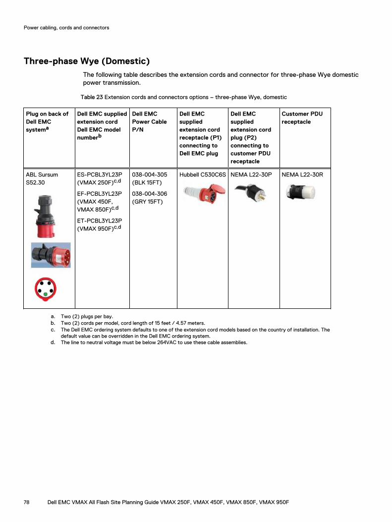
Three-phase Wye (Domestic)The following table describes the extension cords and connector for three-phase Wye domesticpower transmission.
Table 23 Extension cords and connectors options – three-phase Wye, domestic
Plug on back ofDell EMCsystema
Dell EMC suppliedextension cordDell EMC modelnumberb
Dell EMCPower CableP/N
Dell EMCsuppliedextension cordreceptacle (P1)connecting toDell EMC plug
Dell EMCsuppliedextension cordplug (P2)connecting tocustomer PDUreceptacle
Customer PDUreceptacle
ABL SursumS52.30
ES-PCBL3YL23P(VMAX 250F)c,d
EF-PCBL3YL23P(VMAX 450F,VMAX 850F)c,d
ET-PCBL3YL23P(VMAX 950F)c,d
038-004-305(BLK 15FT)
038-004-306(GRY 15FT)
Hubbell C530C6S NEMA L22-30P NEMA L22-30R
a. Two (2) plugs per bay.b. Two (2) cords per model, cord length of 15 feet / 4.57 meters.c. The Dell EMC ordering system defaults to one of the extension cord models based on the country of installation. The
default value can be overridden in the Dell EMC ordering system.d. The line to neutral voltage must be below 264VAC to use these cable assemblies.
Power cabling, cords and connectors
78 Dell EMC VMAX All Flash Site Planning Guide VMAX 250F, VMAX 450F, VMAX 850F, VMAX 950F
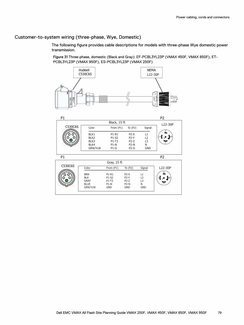
Customer-to-system wiring (three-phase, Wye, Domestic)
The following figure provides cable descriptions for models with three-phase Wye domestic powertransmission.
Figure 31 Three-phase, domestic (Black and Gray): EF-PCBL3YL23P (VMAX 450F, VMAX 850F), ET-PCBL3YL23P (VMAX 950F), ES-PCBL3YL23P (VMAX 250F)
HubbellC530C6S
NEMA
P1 P2
L22-30P
Color From (P1) To (P2) Signal
BLK1 P1-R1 P2-X L1 BLK2 P1-S2 P2-Y L2BLK3 P1-T3 P2-Z L3 BLK4 P1-N P2-N NGRN/YLW P1-G P2-G GND
C530C6SL22-30P
Black, 15 ft
Gray, 15 ft
P1 P2
Color From (P1) To (P2) Signal
BRN P1-R1 P2-X L1 BLK P1-S2 P2-Y L2GRAY P1-T3 P2-Z L3 BLUE P1-N P2-N NGRN/YLW GND GND GND
C530C6SL22-30P
Power cabling, cords and connectors
Dell EMC VMAX All Flash Site Planning Guide VMAX 250F, VMAX 450F, VMAX 850F, VMAX 950F 79

Power cabling, cords and connectors
80 Dell EMC VMAX All Flash Site Planning Guide VMAX 250F, VMAX 450F, VMAX 850F, VMAX 950F
CHAPTER 9
Grounding Racks
Supplemental rack grounding is not required for single bay configurations. Chassis to chassisgrounding is required for systems with multiple bays.
l Grounding requirements........................................................................................................82l Grounding a single bay.......................................................................................................... 82l Chassis to chassis grounding.................................................................................................83
Dell EMC VMAX All Flash Site Planning Guide VMAX 250F, VMAX 450F, VMAX 850F, VMAX 950F 81
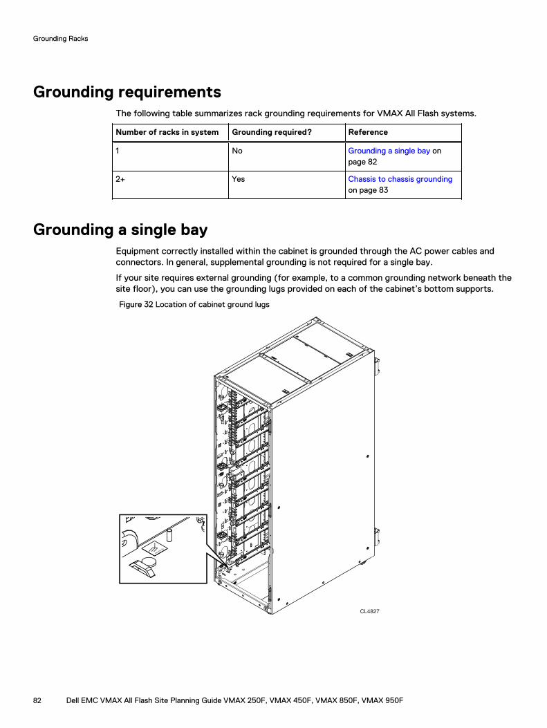
Grounding requirementsThe following table summarizes rack grounding requirements for VMAX All Flash systems.
Number of racks in system Grounding required? Reference
1 No Grounding a single bay onpage 82
2+ Yes Chassis to chassis groundingon page 83
Grounding a single bayEquipment correctly installed within the cabinet is grounded through the AC power cables andconnectors. In general, supplemental grounding is not required for a single bay.
If your site requires external grounding (for example, to a common grounding network beneath thesite floor), you can use the grounding lugs provided on each of the cabinet’s bottom supports.
Figure 32 Location of cabinet ground lugs
CL4827
046-003-3
50
Grounding Racks
82 Dell EMC VMAX All Flash Site Planning Guide VMAX 250F, VMAX 450F, VMAX 850F, VMAX 950F
Chassis to chassis groundingRack to rack chassis ground connections are required to mitigate the risk of large AC powertransients in the data center affecting system performance. Large AC power transients can occurfrom one or a combination of: electrical power grid problems feeding a facility; weak facilitygrounding; powerful lightning storm strikes; or facility power equipment failure.
In multiple bay Dell EMC rack systems, use the rack to rack grounding kit, PN 106-562-209, toprovide chassis to chassis grounding. The kit provides straps for both the front and rear of thecabinets. Both straps must be installed to provide chassis to chassis grounding.
In customer rack systems, mechanisms for tying racks together to provide the ground connectioncan vary based on the rack provided by the customer and site facility preference. PN 106-562-209is a rack to rack grounding kit for Dell EMC racks. The grounding kit may or may not work on racksprovided by the customer due to the variety of ground location positions on racks. If the groundingkit does not work, a site electrician should add a ground cable tying the two racks common frameground points together with 6AWG wire.
Grounding Racks
Dell EMC VMAX All Flash Site Planning Guide VMAX 250F, VMAX 450F, VMAX 850F, VMAX 950F 83

Grounding Racks
84 Dell EMC VMAX All Flash Site Planning Guide VMAX 250F, VMAX 450F, VMAX 850F, VMAX 950F
CHAPTER 10
Dell EMC racking for VMAX 250F
This chapter includes:
l Two system configurations................................................................................................... 86l Requirements for customer components in a rack.................................................................89
Dell EMC VMAX All Flash Site Planning Guide VMAX 250F, VMAX 450F, VMAX 850F, VMAX 950F 85
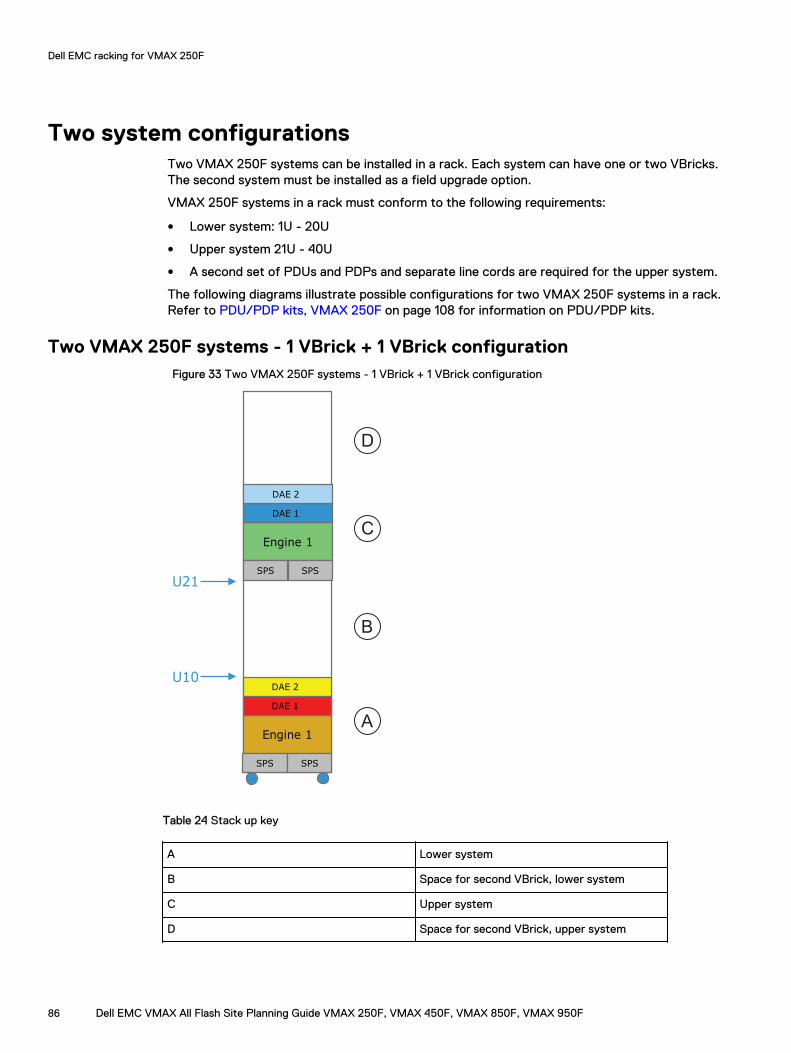
Two system configurationsTwo VMAX 250F systems can be installed in a rack. Each system can have one or two VBricks.The second system must be installed as a field upgrade option.
VMAX 250F systems in a rack must conform to the following requirements:
l Lower system: 1U - 20U
l Upper system 21U - 40U
l A second set of PDUs and PDPs and separate line cords are required for the upper system.
The following diagrams illustrate possible configurations for two VMAX 250F systems in a rack.Refer to PDU/PDP kits, VMAX 250F on page 108 for information on PDU/PDP kits.
Two VMAX 250F systems - 1 VBrick + 1 VBrick configurationFigure 33 Two VMAX 250F systems - 1 VBrick + 1 VBrick configuration
Engine 1
DAE 1
DAE 2
SPS SPS
U10
Engine 1
DAE 1
DAE 2
SPS SPS
U21
A
B
C
D
Table 24 Stack up key
A Lower system
B Space for second VBrick, lower system
C Upper system
D Space for second VBrick, upper system
Dell EMC racking for VMAX 250F
86 Dell EMC VMAX All Flash Site Planning Guide VMAX 250F, VMAX 450F, VMAX 850F, VMAX 950F
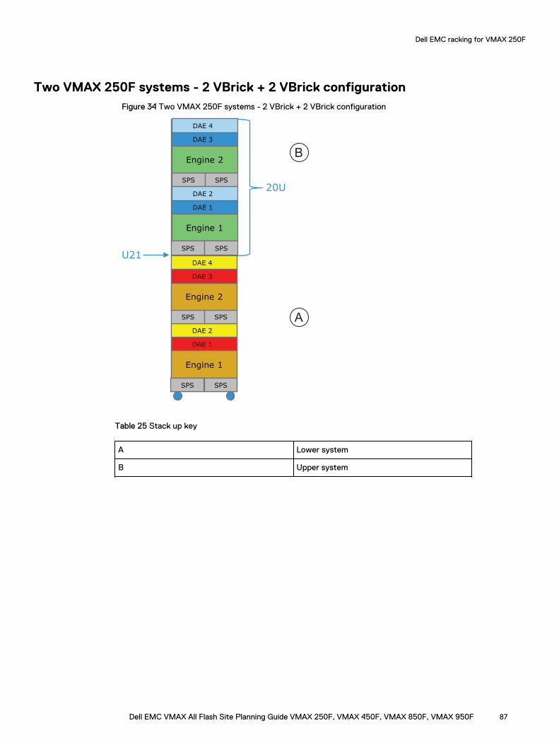
Two VMAX 250F systems - 2 VBrick + 2 VBrick configurationFigure 34 Two VMAX 250F systems - 2 VBrick + 2 VBrick configuration
Engine 1
DAE 1
DAE 2
SPS SPS
Engine 2
DAE 3
DAE 4
SPS SPS
20U
Engine 1
DAE 1
DAE 2
SPS SPS
Engine 2
DAE 3
DAE 4
SPS SPSU21
A
B
Table 25 Stack up key
A Lower system
B Upper system
Dell EMC racking for VMAX 250F
Dell EMC VMAX All Flash Site Planning Guide VMAX 250F, VMAX 450F, VMAX 850F, VMAX 950F 87
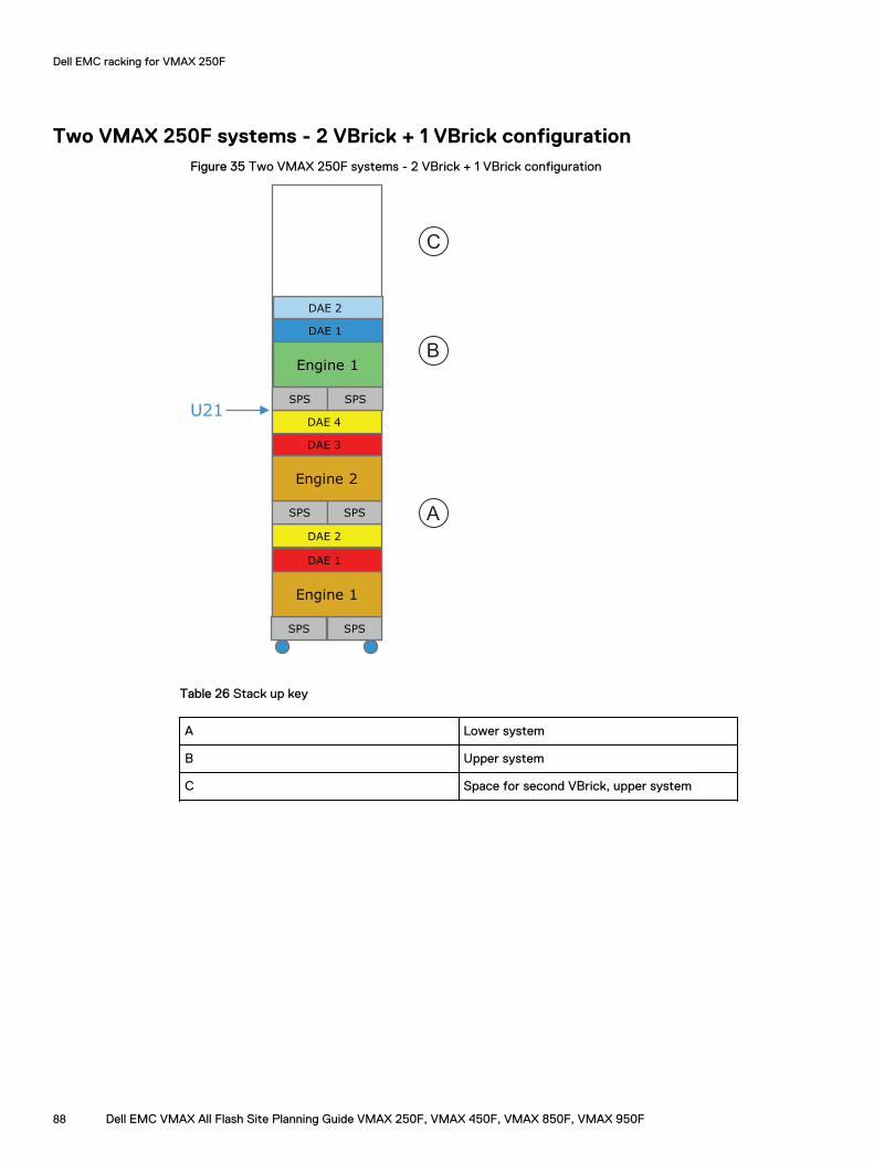
Two VMAX 250F systems - 2 VBrick + 1 VBrick configurationFigure 35 Two VMAX 250F systems - 2 VBrick + 1 VBrick configuration
Engine 1
DAE 1
DAE 2
SPS SPS
SPS SPS
Engine 2
DAE 3
DAE 4
Engine 1
DAE 1
DAE 2
SPS SPSU21
A
B
C
Table 26 Stack up key
A Lower system
B Upper system
C Space for second VBrick, upper system
Dell EMC racking for VMAX 250F
88 Dell EMC VMAX All Flash Site Planning Guide VMAX 250F, VMAX 450F, VMAX 850F, VMAX 950F
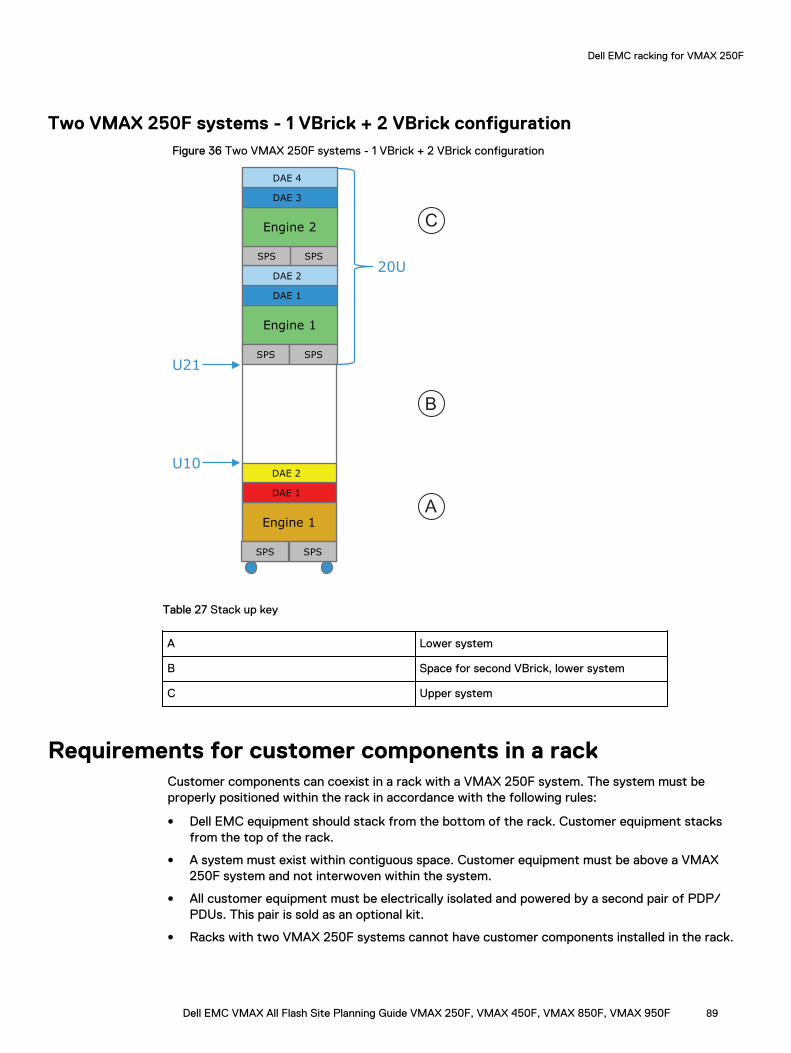
Two VMAX 250F systems - 1 VBrick + 2 VBrick configurationFigure 36 Two VMAX 250F systems - 1 VBrick + 2 VBrick configuration
Engine 1
DAE 1
DAE 2
SPS SPS
20U
Engine 1
DAE 1
DAE 2
SPS SPS
Engine 2
DAE 3
DAE 4
SPS SPS
U10
U21
A
B
C
Table 27 Stack up key
A Lower system
B Space for second VBrick, lower system
C Upper system
Requirements for customer components in a rackCustomer components can coexist in a rack with a VMAX 250F system. The system must beproperly positioned within the rack in accordance with the following rules:
l Dell EMC equipment should stack from the bottom of the rack. Customer equipment stacksfrom the top of the rack.
l A system must exist within contiguous space. Customer equipment must be above a VMAX250F system and not interwoven within the system.
l All customer equipment must be electrically isolated and powered by a second pair of PDP/PDUs. This pair is sold as an optional kit.
l Racks with two VMAX 250F systems cannot have customer components installed in the rack.
Dell EMC racking for VMAX 250F
Dell EMC VMAX All Flash Site Planning Guide VMAX 250F, VMAX 450F, VMAX 850F, VMAX 950F 89

Dell EMC racking for VMAX 250F
90 Dell EMC VMAX All Flash Site Planning Guide VMAX 250F, VMAX 450F, VMAX 850F, VMAX 950F
CHAPTER 11
Third Party Racking Option for VMAX 250F
This chapter includes:
l Computer room requirements............................................................................................... 92l Customer rack requirements................................................................................................. 92l PDU requirements for third party racks, VMAX 250F............................................................93
Dell EMC VMAX All Flash Site Planning Guide VMAX 250F, VMAX 450F, VMAX 850F, VMAX 950F 91
Computer room requirements
The following computer room requirements provide service access and minimize physicaldisruption:
l A minimum of 42 inches (107 cm) front and 30 inches (76 cm) rear clearance is required toprovide adequate airflow and to allow for system service.
Customer rack requirementsThe array components are fully tested at the factory and then transferred to the mini-rack forshipping. Only customer support engineers are authorized to install the system into a customerrack. The original shipping rack, when empty, is returned after the installation is complete.
To ensure successful installation and secure component placement, customer racks must conformto the following requirements:
l National Electrical Manufacturers Association (NEMA) standard for 19-inch cabinets.
l Racks must be at least 38 inches deep, and provide 24 to 32 inch front-to-rear NEMA raildepth.
l Systems require a minimum of 10U of continuous space for one VBrick (minimumconfiguration). 20U of continuous space is required for two VBricks (maximum configuration).
l Threaded hole racks are not supported.
l The customer rack must have two redundant, customer-supplied PDPs and PDUs installed, oneon each side. Each must be connected to customer power.
l Customer rack must support a minimum 850 lbs (385 kg) of weight PLUS the weight of any3rd party components within the rack.
Note: The customer must ensure floor load bearing requirements are met.
l Components and cables installed in customer racks must conform to these configuration rules:
n After installation, components and cables within the rack cannot be moved to availablespace in different rack, or to a different location within the same rack.
n The system must be properly positioned within the rack in accordance with followingphysical placement rules:
– Customer equipment can coexist within the same rack.(The array should stack from the bottom while customer equipment stacks from the topof the rack.)
– A system must exist within contiguous space.(Customer equipment can be below or above the system, but not interwoven within thesystem.)
n Two, independent systems can coexist in a rack. The recommended configuration is:
– Lower system: 1U - 20U
– Upper system 21U - 40U
l Round or square channel openings must support M5 screws that secure rails and components.Clip nuts are provided as required.
l To ensure proper clearance and air flow to the array components, customer supplied frontdoors and standard bezels, if used, must include a minimum of 2.5 inch (6.3 cm) clearancebetween the back surface of the door to the front surface of the vertical NEMA rails.
Third Party Racking Option for VMAX 250F
92 Dell EMC VMAX All Flash Site Planning Guide VMAX 250F, VMAX 450F, VMAX 850F, VMAX 950F
Front and rear doors must also provide:
n A minimum of 60% (evenly distributed) air perforation openings.
n Appropriate access for service personnel, with no items that prevent front or rear access tocomponents.
n Exterior visibility of system LEDs.
PDU requirements for third party racks, VMAX 250FCustomers must provide all power distribution equipment and infrastructure for a VMAX 250Fsystem installed in a customer rack.
General requirements:
l IEC 320-C13 outlets. Minimum quantity of six per PDU for no more than two V-Bricks.
l Carefully plan the connection of VMAX 250F hardware to the available IEC 320-C13 outletssuch that the VMAX 250F load current does not exceed the rating of any power distributioncircuit breakers. Best practice is the circuit breaker operating current at nominal AC inputvoltage should not exceed 80% of the circuit breaker rating.Refer to Component power requirements, VMAX 250F on page 93 for input requirements foreach VMAX 250F component.
Refer to Power distribution equipment for third-party rack, VMAX 250F on page 96 forplanning the number of connections required to support VMAX 250F components.
l Two independent AC power zones with 4800 VA minimum rating for each zone.
l 200-240VAC, 50-60 Hz, available at each IEC 320-C13 outlet.
l Ability to simultaneously turn On/Off all IEC C13 outlets within a power zone.
l Distance from any component AC inlet connection to its corresponding C13 AC outlet can notexceed 66 inches (66 inches is the maximum AC cable length, including routing / service loop)
l Dell EMC does not recommend sharing the same power distribution equipment with customerequipment or multiple VMAX 250F systems. The customer assumes all responsibility forsystem power availability.
l There are no cabling requirements; however, it is recommended to use standard cablingdiagrams as a guide to ensure load balancing.Component cabling is performed by Dell EMC field personnel during installation.
Component power requirements, VMAX 250FThe tables below provide the power requirements and descriptions for individual VMAX 250Fcomponents.
Dell EMC provides a power and weight calculator. Use this calculator to refine the power and heatvalues to more-closely match the hardware configuration for your system.
Engine and 2U SPS power requirements
Table 28 Engine and 2U SPS power requirements
Requirement Description
AC line voltage 200 to 240 V AC ± 10%, single-phase, 47 to63 Hz
AC line current (operating maximum) 6.38 A max, at 200V AC
Third Party Racking Option for VMAX 250F
Dell EMC VMAX All Flash Site Planning Guide VMAX 250F, VMAX 450F, VMAX 850F, VMAX 950F 93
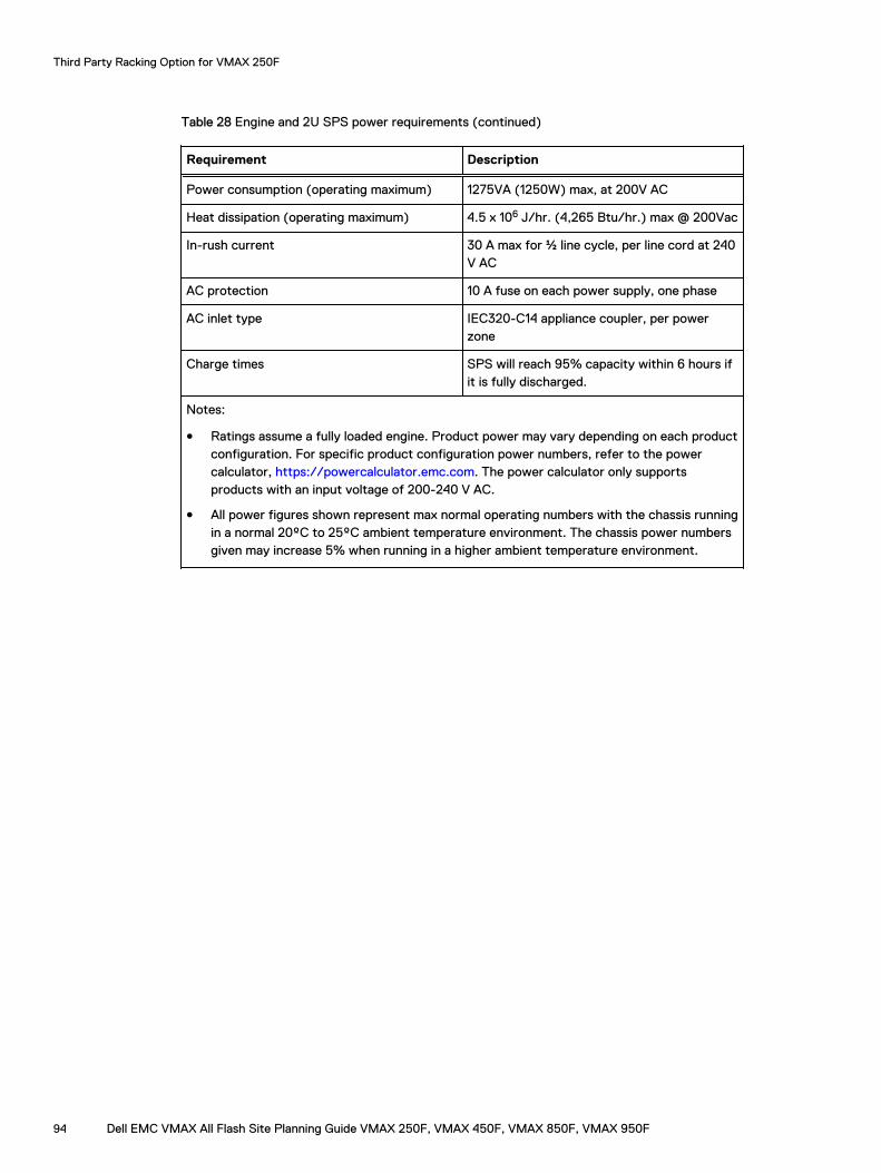
Table 28 Engine and 2U SPS power requirements (continued)
Requirement Description
Power consumption (operating maximum) 1275VA (1250W) max, at 200V AC
Heat dissipation (operating maximum) 4.5 x 10⁶ J/hr. (4,265 Btu/hr.) max @ 200Vac
In-rush current 30 A max for ½ line cycle, per line cord at 240V AC
AC protection 10 A fuse on each power supply, one phase
AC inlet type IEC320-C14 appliance coupler, per powerzone
Charge times SPS will reach 95% capacity within 6 hours ifit is fully discharged.
Notes:
l Ratings assume a fully loaded engine. Product power may vary depending on each productconfiguration. For specific product configuration power numbers, refer to the powercalculator, https://powercalculator.emc.com. The power calculator only supportsproducts with an input voltage of 200-240 V AC.
l All power figures shown represent max normal operating numbers with the chassis runningin a normal 20ºC to 25ºC ambient temperature environment. The chassis power numbersgiven may increase 5% when running in a higher ambient temperature environment.
Third Party Racking Option for VMAX 250F
94 Dell EMC VMAX All Flash Site Planning Guide VMAX 250F, VMAX 450F, VMAX 850F, VMAX 950F
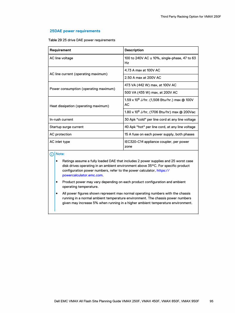
25DAE power requirements
Table 29 25 drive DAE power requirements
Requirement Description
AC line voltage 100 to 240V AC ± 10%, single-phase, 47 to 63Hz
AC line current (operating maximum)4.73 A max at 100V AC
2.50 A max at 200V AC
Power consumption (operating maximum)473 VA (442 W) max, at 100V AC
500 VA (435 W) max, at 200V AC
Heat dissipation (operating maximum)
1.59 x 10⁶ J/hr. (1,508 Btu/hr.) max @ 100VAC
1.80 x 10⁶ J/hr, (1706 Btu/hr) max @ 200Vac
In-rush current 30 Apk "cold" per line cord at any line voltage
Startup surge current 40 Apk "hot" per line cord, at any line voltage
AC protection 15 A fuse on each power supply, both phases
AC inlet type IEC320-C14 appliance coupler, per powerzone
Note:
l Ratings assume a fully loaded DAE that includes 2 power supplies and 25 worst casedisk drives operating in an ambient environment above 35°C. For specific productconfiguration power numbers, refer to the power calculator, https://powercalculator.emc.com.
l Product power may vary depending on each product configuration and ambientoperating temperature.
l All power figures shown represent max normal operating numbers with the chassisrunning in a normal ambient temperature environment. The chassis power numbersgiven may increase 5% when running in a higher ambient temperature environment.
Third Party Racking Option for VMAX 250F
Dell EMC VMAX All Flash Site Planning Guide VMAX 250F, VMAX 450F, VMAX 850F, VMAX 950F 95
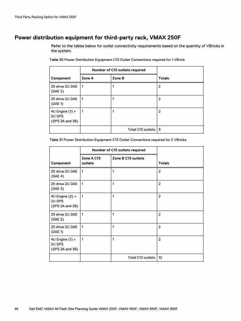
Power distribution equipment for third-party rack, VMAX 250FRefer to the tables below for outlet connectivity requirements based on the quantity of VBricks inthe system.
Table 30 Power Distribution Equipment C13 Outlet Connections required for 1 VBrick
Component
Number of C13 outlets required
TotalsZone A Zone B
25 drive 2U DAE(DAE 2)
1 1 2
25 drive 2U DAE(DAE 1)
1 1 2
4U Engine (1) +2U SPS(SPS 3A and 3B)
1 1 2
Total C13 outlets: 6
Table 31 Power Distribution Equipment C13 Outlet Connections required for 2 VBricks
Component
Number of C13 outlets required
TotalsZone A C13outlets
Zone B C13 outlets
25 drive 2U DAE(DAE 4)
1 1 2
25 drive 2U DAE(DAE 3)
1 1 2
4U Engine (2) +2U SPS(SPS 2A and 2B)
1 1 2
25 drive 2U DAE(DAE 2)
1 1 2
25 drive 2U DAE(DAE 1)
1 1 2
4U Engine (1) +2U SPS(SPS 3A and 3B)
1 1 2
Total C13 outlets: 12
Third Party Racking Option for VMAX 250F
96 Dell EMC VMAX All Flash Site Planning Guide VMAX 250F, VMAX 450F, VMAX 850F, VMAX 950F
CHAPTER 12
Third Party Racking Option for VMAX 450F,VMAX 850F and VMAX 950F
This chapter includes:
l Computer room requirements ...............................................................................................98l Customer rack requirements ................................................................................................ 99l Third party racks with vertical PDUs — RPQ Required ....................................................... 101l Chassis to chassis grounding............................................................................................... 105
Dell EMC VMAX All Flash Site Planning Guide VMAX 250F, VMAX 450F, VMAX 850F, VMAX 950F 97
Computer room requirements
The following computer room requirements provide service access and minimize physicaldisruption:
l To ensure integrity of cables and connections, do not move racks that are secured (bolted)together after installation.
l A minimum of 42 inches (107 cm) front and 30 inches (76 cm) rear clearance is required toprovide adequate airflow and to allow for system service.
Third Party Racking Option for VMAX 450F, VMAX 850F and VMAX 950F
98 Dell EMC VMAX All Flash Site Planning Guide VMAX 250F, VMAX 450F, VMAX 850F, VMAX 950F
Customer rack requirementsThe array components are shipped in a fully tested Dell EMC rack and are installed into thecustomer-supplied rack by Dell EMC customer support engineers only. The original shipping rack,when empty, is returned to Dell EMC after the installation is complete.
To ensure successful installation and secure component placement, customer racks must conformto the following requirements:
l National Electrical Manufacturers Association (NEMA) standard for 19-inch cabinets.
l Individual racks must be empty at the time of installation.
l Threaded hole racks are not supported.
l The cabinet must be in its final location with stabilizing (anti-tip) brackets installed.
l A separate rack that supports a minimum 2000 lb/907 kg of weight must be provided for eachsystem bay.
Note: The customer must ensure floor load bearing requirements are met.
l Components and cables installed in customer racks must conform to these configuration rules:
n Components and cables within a system bay can not be moved to available space indifferent bay, or to a different location within the same bay.
n System must be properly positioned in accordance with physical placement rules.
l Internal depth of at least 43 inches (109 cm) with the front and rear doors closed. Thismeasurement is from the front surface of the NEMA rail to the rear door.
l Round or square channel openings must support M5 screws that secure rails and components.Clip nuts are provided as required.
l Non-dispersed rack-to-rack pass-through cable access at least 3 inches (7.6 cm) in diametermust be available via side panels or horizontal through openings.
l To ensure proper clearance and air flow to the array components, customer supplied frontdoors and standard bezels, if used, must include a minimum of 2.5 inch (6.3 cm) clearancebetween the back surface of the door to the front surface of the vertical NEMA rails.Front and rear doors must also provide:
n A minimum of 60% (evenly distributed) air perforation openings.
n Appropriate access for service personnel, with no items that prevent front or rear access toDell EMC components.
n Exterior visibility of system LEDs.
Third Party Racking Option for VMAX 450F, VMAX 850F and VMAX 950F
Dell EMC VMAX All Flash Site Planning Guide VMAX 250F, VMAX 450F, VMAX 850F, VMAX 950F 99
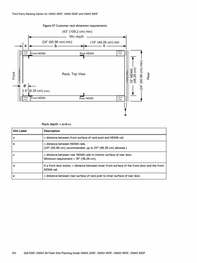
Figure 37 Customer rack dimension requirements
Rack
Post
Re
ar
(19” (48.26 cm) min
Rack
Post
Rack
Post
Rack
Post
Rear NEMA Front NEMA
Front NEMA Rear NEMA
(24
” (6
0.9
6 c
m)
min
)
19
” N
EM
A
Fro
nt
—Fro
nt
Door—
a b c
(24” (60.96 cm) min)
2.5” (6.35 cm) (min)
(48
.26
cm
)—Rear D
oor—
Min depth
(43” (109.2 cm) min)
d
e
Rack, Top View
Rack depth = a+b+c
Dim Label Description
a = distance between front surface of rack post and NEMA rail.
b = distance between NEMA rails.(24" (60.96 cm) recommended, up to 34" (86.36 cm) allowed.)
c = distance between rear NEMA rails to interior surface of rear door.Minimum requirement = 19" (48.26 cm).
d If a front door exists, = distance between inner-front surface of the front door and the frontNEMA rail.
e = distance between rear surface of rack post to inner surface of rear door.
Third Party Racking Option for VMAX 450F, VMAX 850F and VMAX 950F
100 Dell EMC VMAX All Flash Site Planning Guide VMAX 250F, VMAX 450F, VMAX 850F, VMAX 950F
Third party racks with vertical PDUs — RPQ RequiredEach system bay is powered by two redundant power distribution units (PDUs), one PDU for eachpower zone. Rather than use the standard Dell EMC horizontal PDU, the customer can use verticalPDUs via RPQ. The general requirements for third party racks with rear-facing or inward-facingPDUs are listed below.
l Requirements for third party racks with vertical PDUs (inward-facing) on page 104
l Requirements for third party racks with vertical PDUs (rear-facing) on page 102
General requirements for vertical PDUs within third party racks
In addition to meeting standard VMAX array power requirements, vertical PDUs should abide bythe following:
l Both PDUs support AC-line input connectivity and provide outlets for every component in thebay.
l The PDU must be available in the wiring configuration that matches the customer powersupply.Options include:
n Single-phase
n Three-phase Delta
n Three-phase Wye
l Each PDU should meet the following requirements:
n At a minimum, a total of 24 power outlets must be provided.The outlets are divided into six banks with each bank consisting of four IEC 60320 C13individual AC outlets.
n Each bank of outlets is connected to individual branch circuits that are protected by asingle two pole 20 Amp circuit breaker.
n The PDU capacity should exceed the power requirements shown in the Power Calculatorfor the specific max configuration.
n Single PDU mounted per side per Figure 38 on page 102 and Figure 39 on page 104.
If the customer requires power to be supplied from overhead, Dell EMC recommends one of thefollowing:
l Option 1: Replace the rear top cover of the bay with the ceiling routing top cover, described in Overhead routing kit on page 108, which allows the power cables inside the machine to berouted out through the top.
l Option 2: "Drop" the power cables down the hinge side, to the bottom, and route them insidethe machine.
The cables should be dressed to allow all doors to open freely, minimize cable congestion, andprovide access to components within the system.
Third Party Racking Option for VMAX 450F, VMAX 850F and VMAX 950F
Dell EMC VMAX All Flash Site Planning Guide VMAX 250F, VMAX 450F, VMAX 850F, VMAX 950F 101
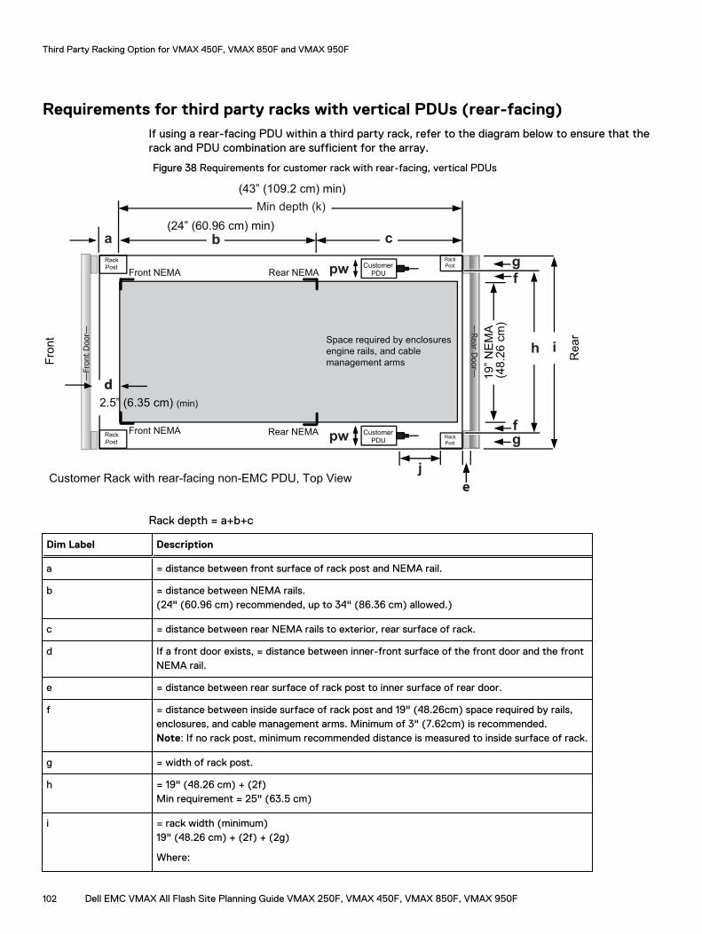
Requirements for third party racks with vertical PDUs (rear-facing)If using a rear-facing PDU within a third party rack, refer to the diagram below to ensure that therack and PDU combination are sufficient for the array.
Figure 38 Requirements for customer rack with rear-facing, vertical PDUs
Customer Rack with rear-facing non-EMC PDU, Top View
Rack
PostRear NEMAFront NEMA
Front NEMA Rear NEMA
Fro
nt
—Fro
nt
Door—
Rack
Post
Rack
Post
Rack
Postpw
pw Customer PDU
Customer PDU
Space required by enclosures
engine rails, and cable
management arms
j
—Rear D
oor—
e
a b c(24” (60.96 cm) min)
Min depth (k)
(43” (109.2 cm) min)
Re
ar
19
” N
EM
A(4
8.2
6 c
m)
d
2.5” (6.35 cm) (min)
fg
f
g
h i
Rack depth = a+b+c
Dim Label Description
a = distance between front surface of rack post and NEMA rail.
b = distance between NEMA rails.(24" (60.96 cm) recommended, up to 34" (86.36 cm) allowed.)
c = distance between rear NEMA rails to exterior, rear surface of rack.
d If a front door exists, = distance between inner-front surface of the front door and the frontNEMA rail.
e = distance between rear surface of rack post to inner surface of rear door.
f = distance between inside surface of rack post and 19" (48.26cm) space required by rails,enclosures, and cable management arms. Minimum of 3" (7.62cm) is recommended.Note: If no rack post, minimum recommended distance is measured to inside surface of rack.
g = width of rack post.
h = 19" (48.26 cm) + (2f)Min requirement = 25" (63.5 cm)
i = rack width (minimum)19" (48.26 cm) + (2f) + (2g)
Where:
Third Party Racking Option for VMAX 450F, VMAX 850F and VMAX 950F
102 Dell EMC VMAX All Flash Site Planning Guide VMAX 250F, VMAX 450F, VMAX 850F, VMAX 950F
Dim Label Description
l f = recommended minimum of 3" (7.62cm)
l g = rear rack post width (if any)
l pw + ½" (1.3cm) ≤ f+g
j ≥ 6" (15.24cm) is a requirement.Distance between rear-facing surface of vertical PDU and the rack post or any other parallelsurface that may interfere with the power cables.
Note: Dimension k is dependent on this value.
k = min depth: b+cWhere:
l j ≥ 6" (15.24cm) is a requirement.
l IF j is ≥ 6" (15.24cm), min rack depth = 43" (109.2cm).
l IF j is < 6" (15.24cm), min rack depth = 43" (109.2cm) + distance required to make j ≥6" (15.24cm).
pw = PDU width
Third Party Racking Option for VMAX 450F, VMAX 850F and VMAX 950F
Dell EMC VMAX All Flash Site Planning Guide VMAX 250F, VMAX 450F, VMAX 850F, VMAX 950F 103
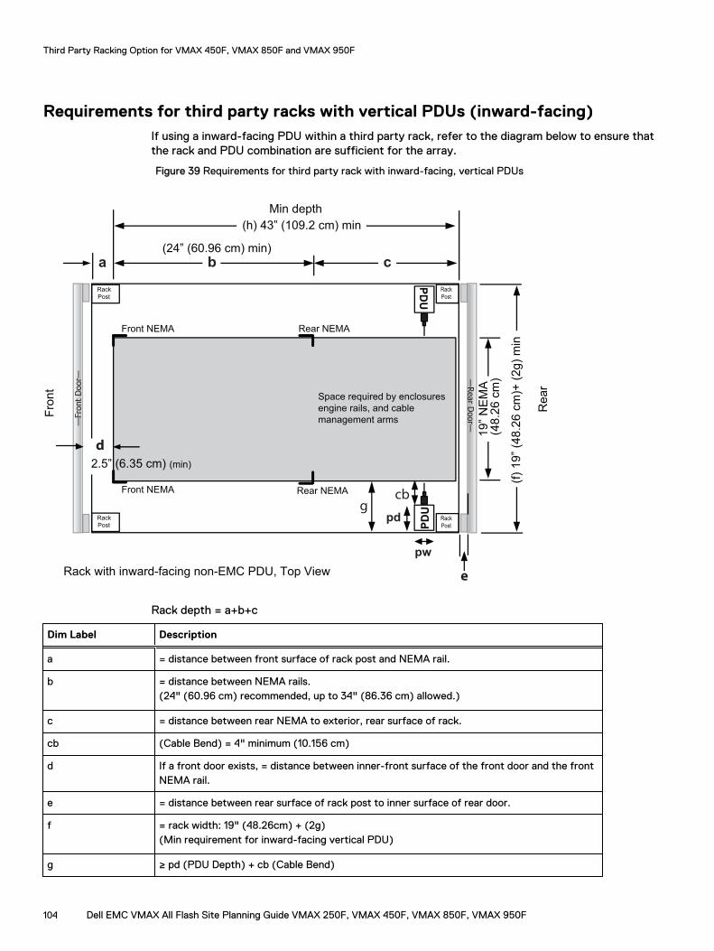
Requirements for third party racks with vertical PDUs (inward-facing)If using a inward-facing PDU within a third party rack, refer to the diagram below to ensure thatthe rack and PDU combination are sufficient for the array.
Figure 39 Requirements for third party rack with inward-facing, vertical PDUs
Rack with inward-facing non-EMC PDU, Top View
Rack
Post
Rear NEMA Front NEMA
Front NEMA Rear NEMA
Fro
nt
—Fro
nt
Door—
Rack
Post
Rack
Post
Rack
Post
Space required by enclosures
engine rails, and cable
management arms PDU
pw
pd
a b(24” (60.96 cm) min)
d
2.5” (6.35 cm) (min)
(f)
19
” (4
8.2
6 c
m)+
(2
g)
min
e
—Rear D
oor—
Re
ar
19
” N
EM
A(4
8.2
6 c
m)
cbg
PDU
c
(h) 43” (109.2 cm) min
Min depth
Rack depth = a+b+c
Dim Label Description
a = distance between front surface of rack post and NEMA rail.
b = distance between NEMA rails.(24" (60.96 cm) recommended, up to 34" (86.36 cm) allowed.)
c = distance between rear NEMA to exterior, rear surface of rack.
cb (Cable Bend) = 4" minimum (10.156 cm)
d If a front door exists, = distance between inner-front surface of the front door and the frontNEMA rail.
e = distance between rear surface of rack post to inner surface of rear door.
f = rack width: 19" (48.26cm) + (2g)(Min requirement for inward-facing vertical PDU)
g ≥ pd (PDU Depth) + cb (Cable Bend)
Third Party Racking Option for VMAX 450F, VMAX 850F and VMAX 950F
104 Dell EMC VMAX All Flash Site Planning Guide VMAX 250F, VMAX 450F, VMAX 850F, VMAX 950F
Dim Label Description
Note: PDU and connected cords cannot interfere with serviceability of system. This includesmaintenance of cable management arms.
h min depth: = b+c (43" (109.2cm) minimum)This is minimum space required for enclosures, engine rails, and cable management arms.
pd = PDU depth
pw = PDU width
Chassis to chassis groundingRack to rack chassis ground connections are required to mitigate the risk of large AC powertransients in the data center affecting system performance. Large AC power transients can occurfrom one or a combination of: electrical power grid problems feeding a facility; weak facilitygrounding; powerful lightning storm strikes; or facility power equipment failure.
In multiple bay Dell EMC rack systems, use the rack to rack grounding kit, PN 106-562-209, toprovide chassis to chassis grounding. The kit provides straps for both the front and rear of thecabinets. Both straps must be installed to provide chassis to chassis grounding.
In customer rack systems, mechanisms for tying racks together to provide the ground connectioncan vary based on the rack provided by the customer and site facility preference. PN 106-562-209is a rack to rack grounding kit for Dell EMC racks. The grounding kit may or may not work on racksprovided by the customer due to the variety of ground location positions on racks. If the groundingkit does not work, a site electrician should add a ground cable tying the two racks common frameground points together with 6AWG wire.
Third Party Racking Option for VMAX 450F, VMAX 850F and VMAX 950F
Dell EMC VMAX All Flash Site Planning Guide VMAX 250F, VMAX 450F, VMAX 850F, VMAX 950F 105

Third Party Racking Option for VMAX 450F, VMAX 850F and VMAX 950F
106 Dell EMC VMAX All Flash Site Planning Guide VMAX 250F, VMAX 450F, VMAX 850F, VMAX 950F
CHAPTER 13
Optional kits
This chapter includes:
l Overhead routing kit............................................................................................................ 108l PDU/PDP kits, VMAX 250F.................................................................................................108l Dispersion kits, VMAX 450F, VMAX 850F............................................................................108l Dispersion kits, VMAX 950F................................................................................................ 109l Securing kits.........................................................................................................................110l GridRunner kit and customer-supplied cable trough............................................................. 110
Dell EMC VMAX All Flash Site Planning Guide VMAX 250F, VMAX 450F, VMAX 850F, VMAX 950F 107
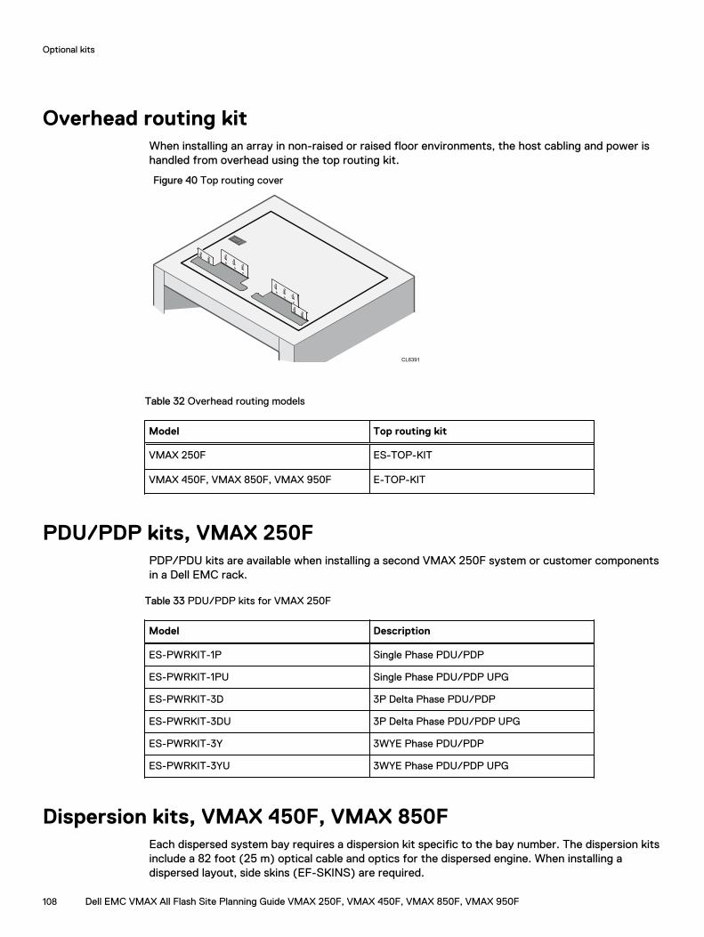
Overhead routing kitWhen installing an array in non-raised or raised floor environments, the host cabling and power ishandled from overhead using the top routing kit.
Figure 40 Top routing cover
Table 32 Overhead routing models
Model Top routing kit
VMAX 250F ES-TOP-KIT
VMAX 450F, VMAX 850F, VMAX 950F E-TOP-KIT
PDU/PDP kits, VMAX 250FPDP/PDU kits are available when installing a second VMAX 250F system or customer componentsin a Dell EMC rack.
Table 33 PDU/PDP kits for VMAX 250F
Model Description
ES-PWRKIT-1P Single Phase PDU/PDP
ES-PWRKIT-1PU Single Phase PDU/PDP UPG
ES-PWRKIT-3D 3P Delta Phase PDU/PDP
ES-PWRKIT-3DU 3P Delta Phase PDU/PDP UPG
ES-PWRKIT-3Y 3WYE Phase PDU/PDP
ES-PWRKIT-3YU 3WYE Phase PDU/PDP UPG
Dispersion kits, VMAX 450F, VMAX 850FEach dispersed system bay requires a dispersion kit specific to the bay number. The dispersion kitsinclude a 82 foot (25 m) optical cable and optics for the dispersed engine. When installing adispersed layout, side skins (EF-SKINS) are required.
Optional kits
108 Dell EMC VMAX All Flash Site Planning Guide VMAX 250F, VMAX 450F, VMAX 850F, VMAX 950F
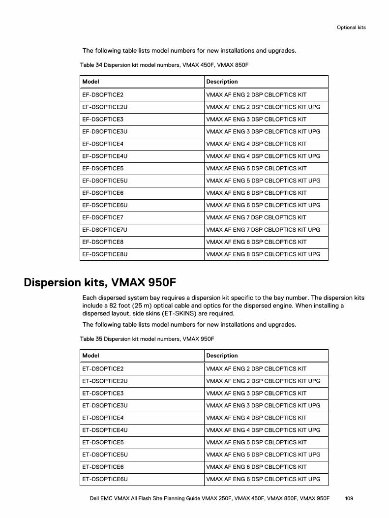
The following table lists model numbers for new installations and upgrades.
Table 34 Dispersion kit model numbers, VMAX 450F, VMAX 850F
Model Description
EF-DSOPTICE2 VMAX AF ENG 2 DSP CBLOPTICS KIT
EF-DSOPTICE2U VMAX AF ENG 2 DSP CBLOPTICS KIT UPG
EF-DSOPTICE3 VMAX AF ENG 3 DSP CBLOPTICS KIT
EF-DSOPTICE3U VMAX AF ENG 3 DSP CBLOPTICS KIT UPG
EF-DSOPTICE4 VMAX AF ENG 4 DSP CBLOPTICS KIT
EF-DSOPTICE4U VMAX AF ENG 4 DSP CBLOPTICS KIT UPG
EF-DSOPTICE5 VMAX AF ENG 5 DSP CBLOPTICS KIT
EF-DSOPTICE5U VMAX AF ENG 5 DSP CBLOPTICS KIT UPG
EF-DSOPTICE6 VMAX AF ENG 6 DSP CBLOPTICS KIT
EF-DSOPTICE6U VMAX AF ENG 6 DSP CBLOPTICS KIT UPG
EF-DSOPTICE7 VMAX AF ENG 7 DSP CBLOPTICS KIT
EF-DSOPTICE7U VMAX AF ENG 7 DSP CBLOPTICS KIT UPG
EF-DSOPTICE8 VMAX AF ENG 8 DSP CBLOPTICS KIT
EF-DSOPTICE8U VMAX AF ENG 8 DSP CBLOPTICS KIT UPG
Dispersion kits, VMAX 950FEach dispersed system bay requires a dispersion kit specific to the bay number. The dispersion kitsinclude a 82 foot (25 m) optical cable and optics for the dispersed engine. When installing adispersed layout, side skins (ET-SKINS) are required.
The following table lists model numbers for new installations and upgrades.
Table 35 Dispersion kit model numbers, VMAX 950F
Model Description
ET-DSOPTICE2 VMAX AF ENG 2 DSP CBLOPTICS KIT
ET-DSOPTICE2U VMAX AF ENG 2 DSP CBLOPTICS KIT UPG
ET-DSOPTICE3 VMAX AF ENG 3 DSP CBLOPTICS KIT
ET-DSOPTICE3U VMAX AF ENG 3 DSP CBLOPTICS KIT UPG
ET-DSOPTICE4 VMAX AF ENG 4 DSP CBLOPTICS KIT
ET-DSOPTICE4U VMAX AF ENG 4 DSP CBLOPTICS KIT UPG
ET-DSOPTICE5 VMAX AF ENG 5 DSP CBLOPTICS KIT
ET-DSOPTICE5U VMAX AF ENG 5 DSP CBLOPTICS KIT UPG
ET-DSOPTICE6 VMAX AF ENG 6 DSP CBLOPTICS KIT
ET-DSOPTICE6U VMAX AF ENG 6 DSP CBLOPTICS KIT UPG
Optional kits
Dell EMC VMAX All Flash Site Planning Guide VMAX 250F, VMAX 450F, VMAX 850F, VMAX 950F 109
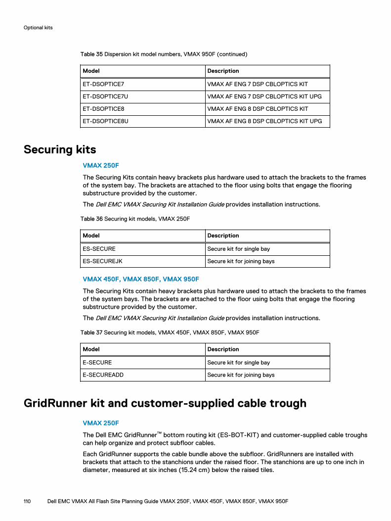
Table 35 Dispersion kit model numbers, VMAX 950F (continued)
Model Description
ET-DSOPTICE7 VMAX AF ENG 7 DSP CBLOPTICS KIT
ET-DSOPTICE7U VMAX AF ENG 7 DSP CBLOPTICS KIT UPG
ET-DSOPTICE8 VMAX AF ENG 8 DSP CBLOPTICS KIT
ET-DSOPTICE8U VMAX AF ENG 8 DSP CBLOPTICS KIT UPG
Securing kitsVMAX 250F
The Securing Kits contain heavy brackets plus hardware used to attach the brackets to the framesof the system bay. The brackets are attached to the floor using bolts that engage the flooringsubstructure provided by the customer.
The Dell EMC VMAX Securing Kit Installation Guide provides installation instructions.
Table 36 Securing kit models, VMAX 250F
Model Description
ES-SECURE Secure kit for single bay
ES-SECUREJK Secure kit for joining bays
VMAX 450F, VMAX 850F, VMAX 950F
The Securing Kits contain heavy brackets plus hardware used to attach the brackets to the framesof the system bays. The brackets are attached to the floor using bolts that engage the flooringsubstructure provided by the customer.
The Dell EMC VMAX Securing Kit Installation Guide provides installation instructions.
Table 37 Securing kit models, VMAX 450F, VMAX 850F, VMAX 950F
Model Description
E-SECURE Secure kit for single bay
E-SECUREADD Secure kit for joining bays
GridRunner kit and customer-supplied cable trough
VMAX 250F
The Dell EMC GridRunner™ bottom routing kit (ES-BOT-KIT) and customer-supplied cable troughscan help organize and protect subfloor cables.
Each GridRunner supports the cable bundle above the subfloor. GridRunners are installed withbrackets that attach to the stanchions under the raised floor. The stanchions are up to one inch indiameter, measured at six inches (15.24 cm) below the raised tiles.
Optional kits
110 Dell EMC VMAX All Flash Site Planning Guide VMAX 250F, VMAX 450F, VMAX 850F, VMAX 950F
To ensure sufficient support of the cable bundle, a GridRunner should be installed every twometers.
Table 38 Bottom routing model, VMAX 250F
Model Description
ES-BOT-KIT Bottom routing kit
VMAX 450F, VMAX 850F, VMAX 950F
The EMC GridRunner™ bottom routing kit (E-BOT-KIT) and customer-supplied cable troughs canhelp organize and protect subfloor cables that connect separated bays. GridRunners reduce thevertical drop of the dispersion cables, which may increase the distance between the separatedbays.
Each GridRunner supports the cable bundle above the subfloor. GridRunners are installed withbrackets that attach to the stanchions under the raised floor. The stanchions are up to one inch indiameter, measured at six inches (15.24 cm) below the raised tiles.
To ensure sufficient support of the cable bundle, a GridRunner should be installed every twometers.
Table 39 Bottom routing model, VMAX 450F, VMAX 850F, VMAX 950F
Model Description
E-BOT-KIT a Bottom routing kit
a. GridRunner basket for supporting cables beneath the floor for dispersed bays.
Optional kits
Dell EMC VMAX All Flash Site Planning Guide VMAX 250F, VMAX 450F, VMAX 850F, VMAX 950F 111

Optional kits
112 Dell EMC VMAX All Flash Site Planning Guide VMAX 250F, VMAX 450F, VMAX 850F, VMAX 950F
APPENDIX
Best Practices for AC Power Connections
This chapter includes:
l Best practices overview for AC power connections..............................................................114l Selecting the proper AC power connection procedure......................................................... 115l Procedure A: Working with the customer's electrician onsite............................................... 116l Procedure B: Verify and connect..........................................................................................127l Procedure C: Obtain customer verification.......................................................................... 128l PDU labels........................................................................................................................... 128l AC power specifications....................................................................................................... 131
Dell EMC VMAX All Flash Site Planning Guide VMAX 250F, VMAX 450F, VMAX 850F, VMAX 950F 113
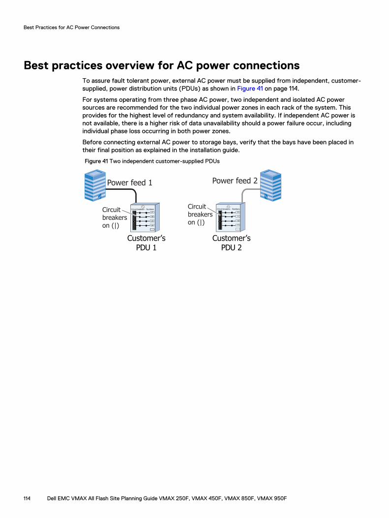
Best practices overview for AC power connectionsTo assure fault tolerant power, external AC power must be supplied from independent, customer-supplied, power distribution units (PDUs) as shown in Figure 41 on page 114.
For systems operating from three phase AC power, two independent and isolated AC powersources are recommended for the two individual power zones in each rack of the system. Thisprovides for the highest level of redundancy and system availability. If independent AC power isnot available, there is a higher risk of data unavailability should a power failure occur, includingindividual phase loss occurring in both power zones.
Before connecting external AC power to storage bays, verify that the bays have been placed intheir final position as explained in the installation guide.
Figure 41 Two independent customer-supplied PDUs
Customer’sPDU 1
Customer’sPDU 2
Circuit breakerson (|)
Circuit breakerson (|)
Circuit breakers - Numbers
27
28
29
30
Circuit breakers - Numbers
...
8
9
10
11
...
Power feed 1 Power feed 2
Best Practices for AC Power Connections
114 Dell EMC VMAX All Flash Site Planning Guide VMAX 250F, VMAX 450F, VMAX 850F, VMAX 950F
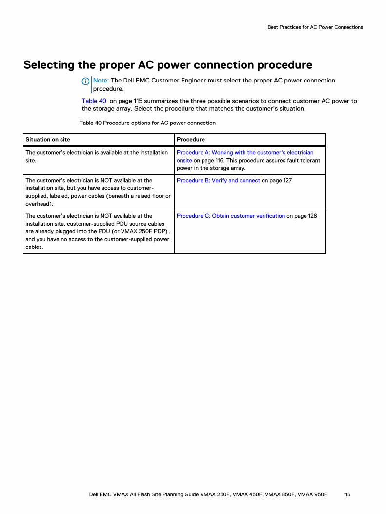
Selecting the proper AC power connection procedureNote: The Dell EMC Customer Engineer must select the proper AC power connectionprocedure.
Table 40 on page 115 summarizes the three possible scenarios to connect customer AC power tothe storage array. Select the procedure that matches the customer's situation.
Table 40 Procedure options for AC power connection
Situation on site Procedure
The customer’s electrician is available at the installationsite.
Procedure A: Working with the customer's electricianonsite on page 116. This procedure assures fault tolerantpower in the storage array.
The customer’s electrician is NOT available at theinstallation site, but you have access to customer-supplied, labeled, power cables (beneath a raised floor oroverhead).
Procedure B: Verify and connect on page 127
The customer’s electrician is NOT available at theinstallation site, customer-supplied PDU source cablesare already plugged into the PDU (or VMAX 250F PDP) ,and you have no access to the customer-supplied powercables.
Procedure C: Obtain customer verification on page 128
Best Practices for AC Power Connections
Dell EMC VMAX All Flash Site Planning Guide VMAX 250F, VMAX 450F, VMAX 850F, VMAX 950F 115
Procedure A: Working with the customer's electrician onsiteUse this procedure if the customer’s electrician is available at the installation site.
This procedure requires three basic tasks that alternate between the customer's electrician, theDell EMC CE and back to the customer's electrician.
l Task 1: Customer's electrician
l Task 2: Dell EMC Customer Engineer (CE)
l Task 3: Customer's electrician
Best Practices for AC Power Connections
116 Dell EMC VMAX All Flash Site Planning Guide VMAX 250F, VMAX 450F, VMAX 850F, VMAX 950F
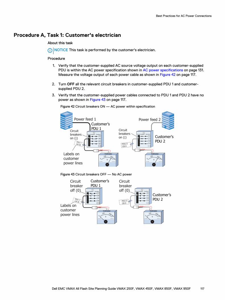
Procedure A, Task 1: Customer's electricianAbout this task
NOTICE This task is performed by the customer's electrician.
Procedure
1. Verify that the customer-supplied AC source voltage output on each customer-suppliedPDU is within the AC power specification shown in AC power specifications on page 131.Measure the voltage output of each power cable as shown in Figure 42 on page 117.
2. Turn OFF all the relevant circuit breakers in customer-supplied PDU 1 and customer-supplied PDU 2.
3. Verify that the customer-supplied power cables connected to PDU 1 and PDU 2 have nopower as shown in Figure 43 on page 117.
Figure 42 Circuit breakers ON — AC power within specification
Customer’sPDU 1
Customer’sPDU 2
Circuit breakerson (|)
Circuit breakerson (|)
Circuit breakers - Numbers
27
28
29
30
Circuit breakers - Numbers
...
8
9
10
11
...
Labels on customer power lines
Power feed 1 Power feed 2
PDU 1CB 28
PDU 2
CB 9
Voltmeter
TYPE PM89 CLASS 25 01
0
100 240300V
Voltmeter
TYPE PM89 CLASS 25 01
0
100 240300V
Figure 43 Circuit breakers OFF — No AC power
Customer’sPDU 1
Customer’sPDU 2
Circuit breakeroff (0)
Circuit breakeroff (0)Circuit breakers - Numbers
27
28
29
30
Circuit breakers - Numbers
...
8
9
10
11
...
PDU 2
CB 9
PDU 1CB 28
Labels on customer power lines
Voltmeter
TYPE PM89 CLASS 25 01
0
100 240300V
Voltmeter
TYPE PM89 CLASS 25 01
0
100 240300V
Best Practices for AC Power Connections
Dell EMC VMAX All Flash Site Planning Guide VMAX 250F, VMAX 450F, VMAX 850F, VMAX 950F 117
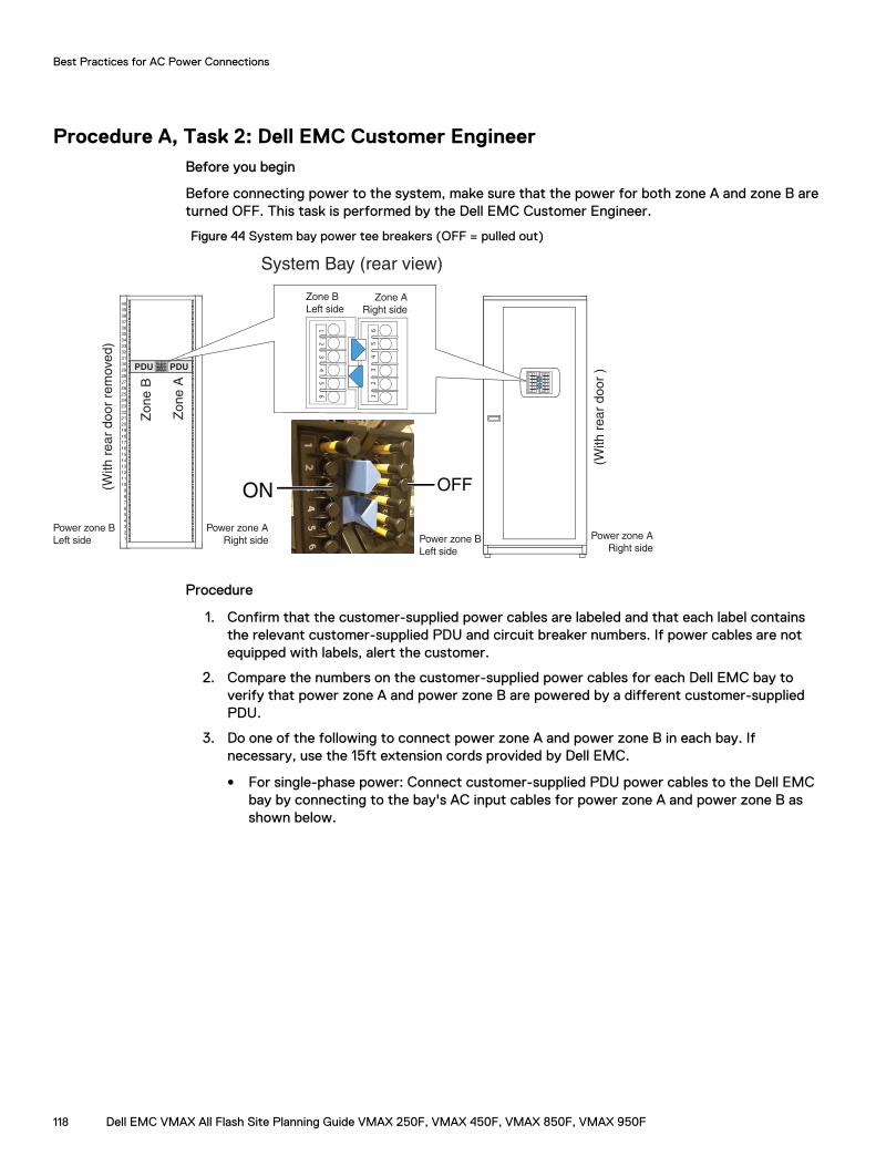
Procedure A, Task 2: Dell EMC Customer EngineerBefore you begin
Before connecting power to the system, make sure that the power for both zone A and zone B areturned OFF. This task is performed by the Dell EMC Customer Engineer.
Figure 44 System bay power tee breakers (OFF = pulled out)
2
1
3
4
5
6
7
8
9
10
11
12
13
14
15
16
17
18
19
20
21
22
23
24
25
26
27
28
29
30
31
32
33
34
35
36
37
38
39
40
PDU PDU
System Bay (rear view)
Zone B
Zone A
12
34
56
12
34
56
Power zone B
Left side
Power zone A
Right side1
23
45
6
12
34
56
Zone A
Right side
Zone B
Left side
Power zone B
Left side
Power zone A
Right side
(With r
ear
door
rem
ove
d)
(With r
ear
door
)
ON OFF
12
34
56
12
34
56
Procedure
1. Confirm that the customer-supplied power cables are labeled and that each label containsthe relevant customer-supplied PDU and circuit breaker numbers. If power cables are notequipped with labels, alert the customer.
2. Compare the numbers on the customer-supplied power cables for each Dell EMC bay toverify that power zone A and power zone B are powered by a different customer-suppliedPDU.
3. Do one of the following to connect power zone A and power zone B in each bay. Ifnecessary, use the 15ft extension cords provided by Dell EMC.
l For single-phase power: Connect customer-supplied PDU power cables to the Dell EMCbay by connecting to the bay's AC input cables for power zone A and power zone B asshown below.
Best Practices for AC Power Connections
118 Dell EMC VMAX All Flash Site Planning Guide VMAX 250F, VMAX 450F, VMAX 850F, VMAX 950F
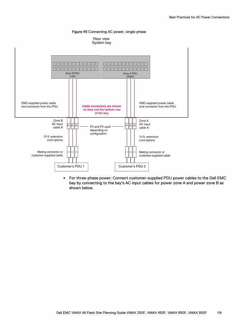
Figure 45 Connecting AC power, single-phase
Customer’s PDU 1
Zone B
AC input
cable B
15 ft. extension
cord options
Mating connector or
customer-supplied cable
Customer’s PDU 2
Zone A
AC input
cable A
15 ft. extension
cord options
Mating connector or
customer-supplied cable
EMC-supplied power cable
and connector from the PDUCable connectors are shown
as they exit the bottom rear
of the bay.
Rear viewSystem bay
Zone B PDU
(Left)Zone A PDU
(Right)
EMC-supplied power cable
and connector from the PDU
P1 P2 P3 P1 P2 P3P2 and P3 used
depending on
configuration
l For three-phase power: Connect customer-supplied PDU power cables to the Dell EMCbay by connecting to the bay's AC input cables for power zone A and power zone B asshown below.
Best Practices for AC Power Connections
Dell EMC VMAX All Flash Site Planning Guide VMAX 250F, VMAX 450F, VMAX 850F, VMAX 950F 119
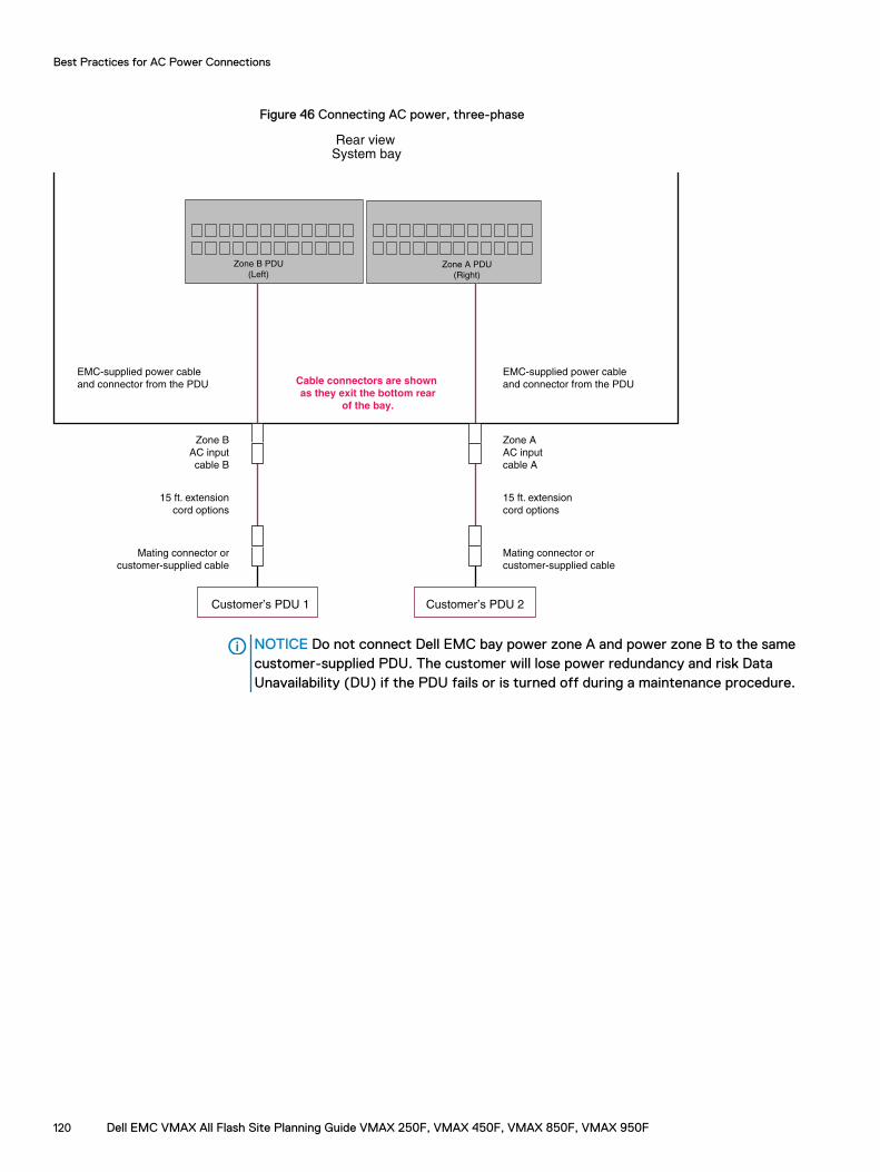
Figure 46 Connecting AC power, three-phase
Customer’s PDU 1
Zone B
AC input
cable B
15 ft. extension
cord options
Mating connector or
customer-supplied cable
Customer’s PDU 2
Zone A
AC input
cable A
15 ft. extension
cord options
Mating connector or
customer-supplied cable
EMC-supplied power cable
and connector from the PDU
Rear viewSystem bay
Zone B PDU
(Left)
Zone A PDU
(Right)
EMC-supplied power cable
and connector from the PDU
Zone B PDU
(Left)Zone A PDU
(Right)
Cable connectors are shown
as they exit the bottom rear
of the bay.
NOTICE Do not connect Dell EMC bay power zone A and power zone B to the samecustomer-supplied PDU. The customer will lose power redundancy and risk DataUnavailability (DU) if the PDU fails or is turned off during a maintenance procedure.
Best Practices for AC Power Connections
120 Dell EMC VMAX All Flash Site Planning Guide VMAX 250F, VMAX 450F, VMAX 850F, VMAX 950F
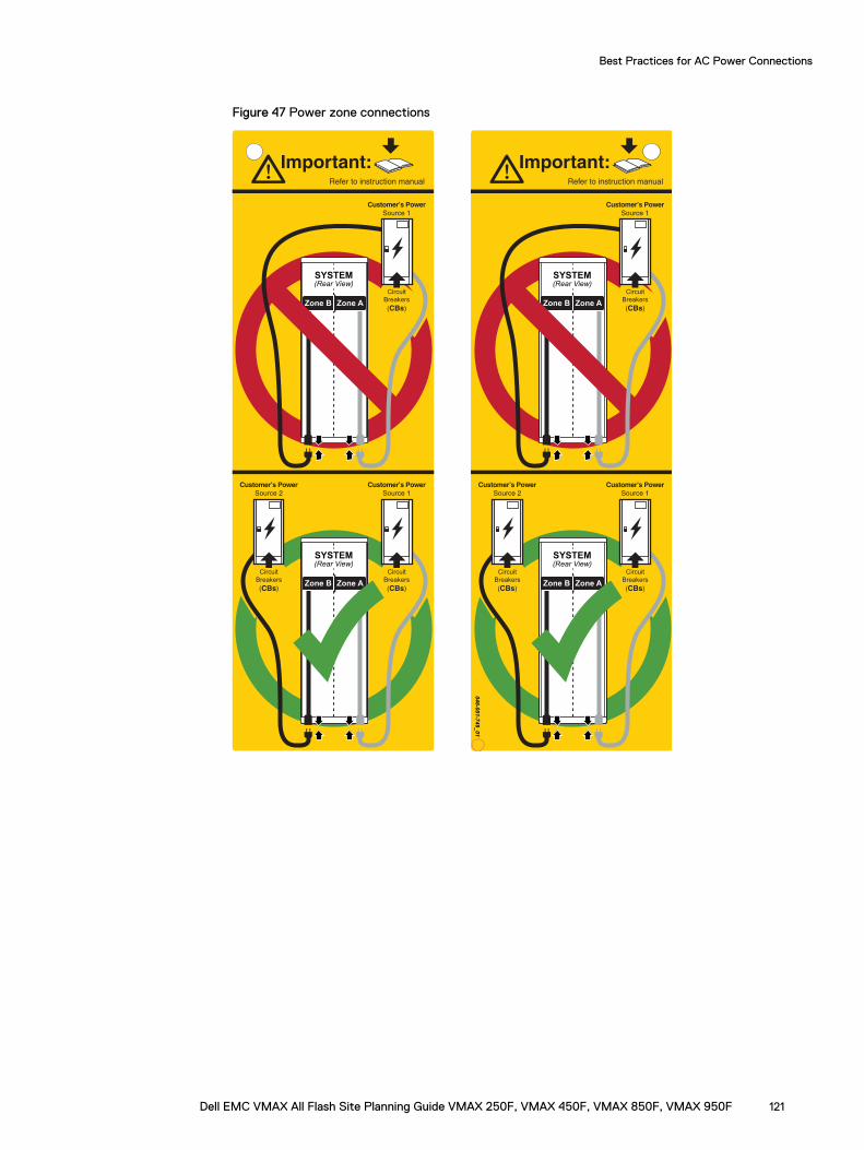
Figure 47 Power zone connections
:tnatropmIlaunam noitcurtsni ot refeR
Zone B Zone A
(Rear View)SYSTEM
Customer’s Power
Source 1
Circuit
Breakers
(CBs)
Zone B Zone A
(Rear View)SYSTEM
Customer’s Power
Source 1
Circuit
Breakers
(CBs)
Customer’s Power
Source 2
Circuit
Breakers
(CBs)
:tnatropmIlaunam noitcurtsni ot refeR
Zone B Zone A
(Rear View)SYSTEM
Customer’s Power
Source 1
Circuit
Breakers
(CBs)
Zone B Zone A
(Rear View)SYSTEM
Customer’s Power
Source 1
Circuit
Breakers
(CBs)
Customer’s Power
Source 2
Circuit
Breakers
(CBs)
046-001-749_01
Best Practices for AC Power Connections
Dell EMC VMAX All Flash Site Planning Guide VMAX 250F, VMAX 450F, VMAX 850F, VMAX 950F 121
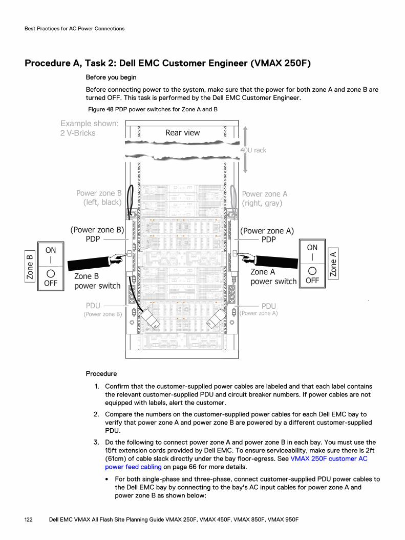
Procedure A, Task 2: Dell EMC Customer Engineer (VMAX 250F)Before you begin
Before connecting power to the system, make sure that the power for both zone A and zone B areturned OFF. This task is performed by the Dell EMC Customer Engineer.
Figure 48 PDP power switches for Zone A and B
Rear viewExample shown:
2 V-Bricks
PDP
10
10
A
B
10
10
A
B
ON
I
OFF
O
ON
I
OFF
O
ON
I
OFF
O
ON
I
OFF
O
ON
I
OFF
O
ON
I
OFF
O
PDU
40U rack
PDP
PDU
Power zone A(right, gray)
Power zone B(left, black)
(Power zone B)
(Power zone B) (Power zone A)
(Power zone A)
ON|
OFF
Zone A
Zone A power switch
ON|
OFF
Zone B
Zone B power switch
Power zone B(left, black)
40U rack
Power zone A(right, gray)
Example shown:
2 V-Bricks
PDU(Power zone A)
PDU(Power zone B)
Procedure
1. Confirm that the customer-supplied power cables are labeled and that each label containsthe relevant customer-supplied PDU and circuit breaker numbers. If power cables are notequipped with labels, alert the customer.
2. Compare the numbers on the customer-supplied power cables for each Dell EMC bay toverify that power zone A and power zone B are powered by a different customer-suppliedPDU.
3. Do the following to connect power zone A and power zone B in each bay. You must use the15ft extension cords provided by Dell EMC. To ensure serviceability, make sure there is 2ft(61cm) of cable slack directly under the bay floor-egress. See VMAX 250F customer ACpower feed cabling on page 66 for more details.
l For both single-phase and three-phase, connect customer-supplied PDU power cables tothe Dell EMC bay by connecting to the bay's AC input cables for power zone A andpower zone B as shown below:
Best Practices for AC Power Connections
122 Dell EMC VMAX All Flash Site Planning Guide VMAX 250F, VMAX 450F, VMAX 850F, VMAX 950F
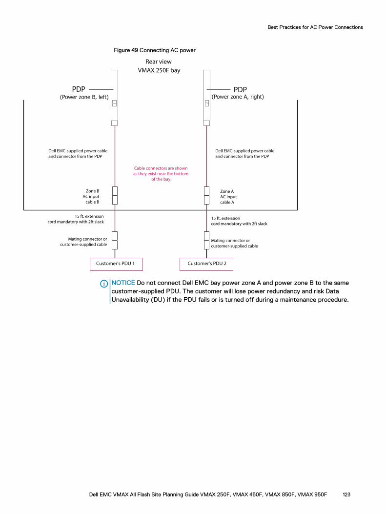
Figure 49 Connecting AC power
Customer’s PDU 1
Zone B
AC input
cable B
15 ft. extension
cord mandatory with 2ft slack
Mating connector or
customer-supplied cable
Customer’s PDU 2
Zone A
AC input
cable A
15 ft. extension
cord mandatory with 2ft slack
Mating connector or
customer-supplied cable
Dell EMC-supplied power cable
and connector from the PDP
Cable connectors are shown
as they exist near the bottom
of the bay.
Rear view
VMAX 250F bay
Dell EMC-supplied power cable
and connector from the PDP
PDP PDP(Power zone B, left) (Power zone A, right)
NOTICE Do not connect Dell EMC bay power zone A and power zone B to the samecustomer-supplied PDU. The customer will lose power redundancy and risk DataUnavailability (DU) if the PDU fails or is turned off during a maintenance procedure.
Best Practices for AC Power Connections
Dell EMC VMAX All Flash Site Planning Guide VMAX 250F, VMAX 450F, VMAX 850F, VMAX 950F 123
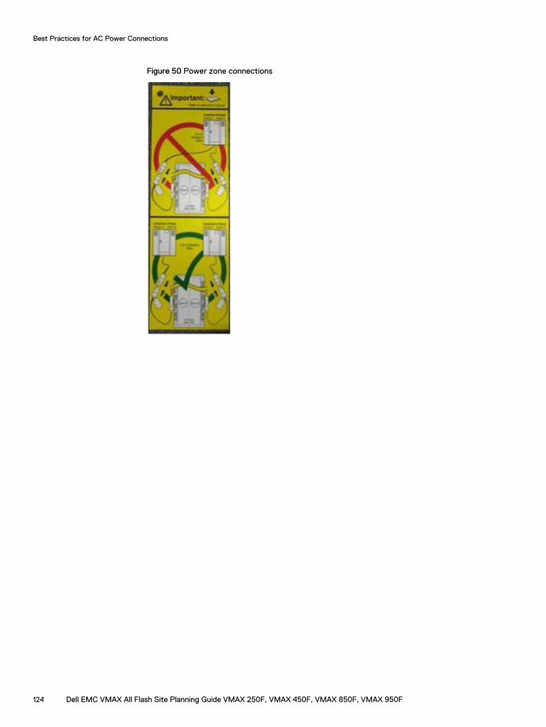
Figure 50 Power zone connections
Best Practices for AC Power Connections
124 Dell EMC VMAX All Flash Site Planning Guide VMAX 250F, VMAX 450F, VMAX 850F, VMAX 950F
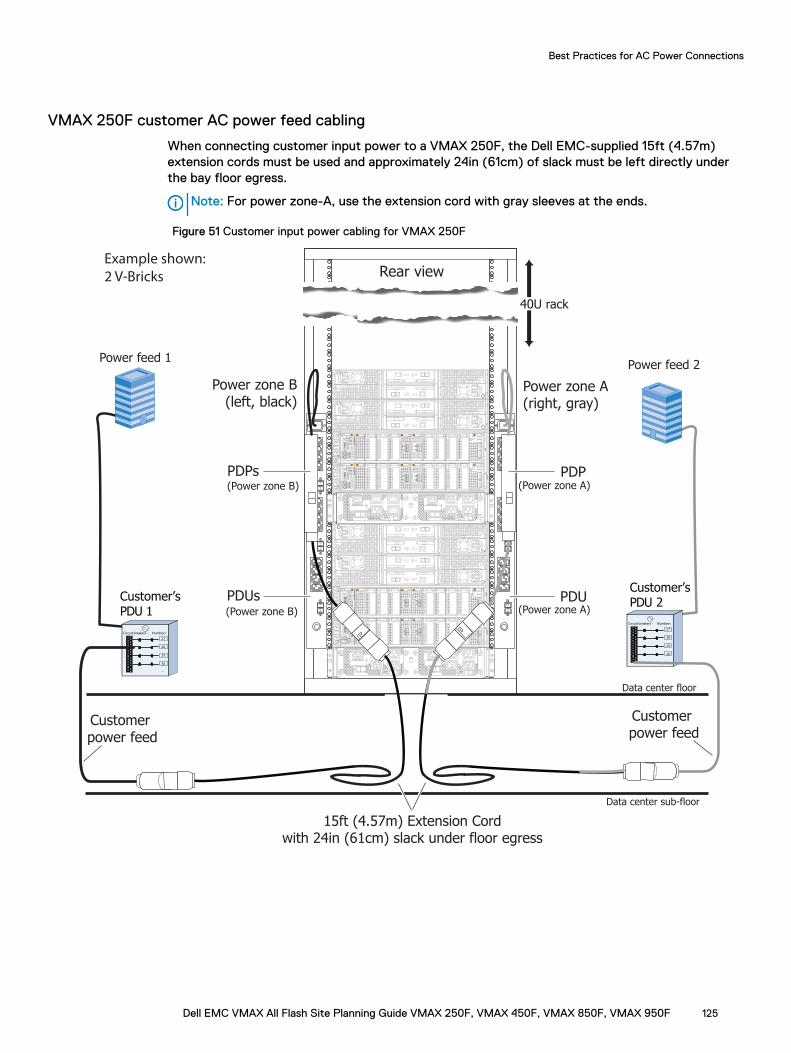
VMAX 250F customer AC power feed cabling
When connecting customer input power to a VMAX 250F, the Dell EMC-supplied 15ft (4.57m)extension cords must be used and approximately 24in (61cm) of slack must be left directly underthe bay floor egress.
Note: For power zone-A, use the extension cord with gray sleeves at the ends.
Figure 51 Customer input power cabling for VMAX 250F
Rear viewExample shown:
2 V-Bricks
PDPs
Customer’sPDU 2
Power feed 2
Customer’sPDU 1
Circuit breakers - Numbers
27
28
29
30
...
Circuit breakers - Numbers
27
28
29
30
...
Power feed 1
10
10
A
B
10
10
A
B
ON
I
OFF
O
ON
I
OFF
O
ON
I
OFF
O
ON
I
OFF
O
ON
I
OFF
O
ON
I
OFF
O
15ft (4.57m) Extension Cordwith 24in (61cm) slack under floor egress
Customer power feed
Customer power feed
PDUs
40U rack
PDP
PDU
Power zone A(right, gray)
Power zone B(left, black)
(Power zone B)
(Power zone B) (Power zone A)
(Power zone A)
Data center sub-floor
Data center floor
Best Practices for AC Power Connections
Dell EMC VMAX All Flash Site Planning Guide VMAX 250F, VMAX 450F, VMAX 850F, VMAX 950F 125
Procedure A, Task 3: Customer's electricianAbout this task
Note: This task is performed by the customer's electrician.
Procedure
1. Working with the Dell EMC Customer Engineer, turn ON all the relevant circuit breakers incustomer-supplied PDU 2.
Verify that only power supply and/or SPS LEDs in power zone A are ON or flashing green inevery bay in the array.
CAUTION The bay is incorrectly wired if all (power zone A and B) power supply and/orSPS LEDs in a bay are ON or flashing green. Check that the AC power to both storagebay power zones is not supplied by a single PDU (customer-supplied PDU 2). The wiringmust be corrected before moving on to the next step.
2. Turn OFF the relevant circuit breakers in customer-supplied PDU 2.
Verify that the power supply and/or SPS LEDs that turned green in the previous stepchanged from green to OFF and/or flashing yellow. The yellow SPS lights flash for amaximum of 5 minutes.
Note: Power supplies connected to an SPS continue to have green lights ON while theSPS yellow light continues to flash indicating the SPS is providing on-battery power.
3. Repeat step 1 and step 2 for power zone B and customer-supplied PDU 1.
4. Turn ON all the relevant circuit breakers in customer-supplied PDU 1 and customer-suppliedPDU 2.
5. Label the PDUs as described in PDU labels on page 128.
Best Practices for AC Power Connections
126 Dell EMC VMAX All Flash Site Planning Guide VMAX 250F, VMAX 450F, VMAX 850F, VMAX 950F
Procedure B: Verify and connectAbout this task
Perform this procedure if the two conditions listed below are true:
l You have access to customer-supplied, labeled, power cables (beneath raised floor oroverhead).
l The customer's electrician is not available at the installation site.
This procedure requires the Dell EMC Customer Engineer to verify that the customer's electricianhas complied with power specifications. Once verified, the Dell EMC Customer Engineer makes therequired power connections overhead or under the floor.
Procedure
1. Have the customer verify that their electrician has complied with power specifications forvoltage levels and redundancy. If the customer cannot verify this, provide them with a copyof Procedure A. Inform the customer that their array may prematurely shut down in theevent of a site power issue.
2. Access the labeled, power cables (beneath raised floor or overhead) to verify that thecustomer-supplied power cables are properly labeled as shown in Figure 43 on page 117 anddescribed in Procedure A, Task 2.
3. Compare the numbers on the customer-supplied power cables for each storage bay to verifythat power zone A and power zone B are powered by a different customer-supplied PDU.
4. Connect the customer's PDU AC cables to the storage bay power zones as described inProcedure A, Task 2.
5. Record the customer-supplied PDU information as described in Procedure A, Task 2.
6. Label the PDUs as described in PDU labels on page 128.
Best Practices for AC Power Connections
Dell EMC VMAX All Flash Site Planning Guide VMAX 250F, VMAX 450F, VMAX 850F, VMAX 950F 127
Procedure C: Obtain customer verificationAbout this task
Perform this procedure if the three conditions listed below are true:
l The customer-supplied PDU source cables are already plugged into the storage bay PDU.
l You have no access to the area below the raised floor.
l The customer's electrician is not available at the installation site.
Procedure
1. Have the customer verify that their electrician has complied with power specifications forvoltage levels and redundancy. If the customer cannot verify this, provide them with a copyof Procedure A. Inform the customer that their array may prematurely shut down in theevent of a site power issue.
2. Record the customer-supplied PDU information (AC source voltage) as described in step 1of Procedure A, Task 1: Customer's electrician on page 117 and label the PDUs as describedin PDU labels on page 128.
PDU labelsBefore applying labels to the PDUs, one of the following procedures must have been completed:
l Procedure A: Working with the customer's electrician onsite on page 116
l Procedure B: Verify and connect on page 127
l Procedure C: Obtain customer verification on page 128
If necessary, see Selecting the proper AC power connection procedure on page 115 to select thecorrect procedure.
PDU label part numbers
VMAX 250F
Table 41 VMAX 250F label part numbers
PN Description Location
PN 046-003-593 LABEL: CUSTOMER PDUINFORMATION
OPEN ME FIRST KIT, PN 106-887-093
VMAX 450F, VMAX 850F, VMAX 950F
Table 42 VMAX 450F, VMAX 850F, VMAX 950F label part numbers, Dell EMC racks
For... Use PN Description Location
All bays PN 046-001-750 LABEL: CUSTOMER 1P 3P PDUINFO WRITEABLE
OPEN ME FIRST, KIT, PN 106-887-026
Best Practices for AC Power Connections
128 Dell EMC VMAX All Flash Site Planning Guide VMAX 250F, VMAX 450F, VMAX 850F, VMAX 950F
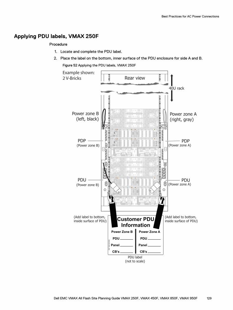
Applying PDU labels, VMAX 250FProcedure
1. Locate and complete the PDU label.
2. Place the label on the bottom, inner surface of the PDU enclosure for side A and B.
Figure 52 Applying the PDU labels, VMAX 250F
Rear viewExample shown:
2 V-Bricks
PDP
10
10
A
B
10
10
A
B
ONI
OFFO
ONI
OFFO
ONI
OFFO
ONI
OFFO
ONI
OFFO
ONI
OFFO
PDU
40U rack
PDP
PDU
Power zone A(right, gray)
Power zone B(left, black)
(Power zone B)
(Power zone B) (Power zone A)
(Power zone A)
046-003-593_A02
Power Zone B Power Zone A
Customer PDU
Information
PDU
Panel
CB’s
PDU
Panel
CB’s
(Add label to bottom,inside surface of PDU)
(Add label to bottom,inside surface of PDU)
PDU label(not to scale)
Best Practices for AC Power Connections
Dell EMC VMAX All Flash Site Planning Guide VMAX 250F, VMAX 450F, VMAX 850F, VMAX 950F 129
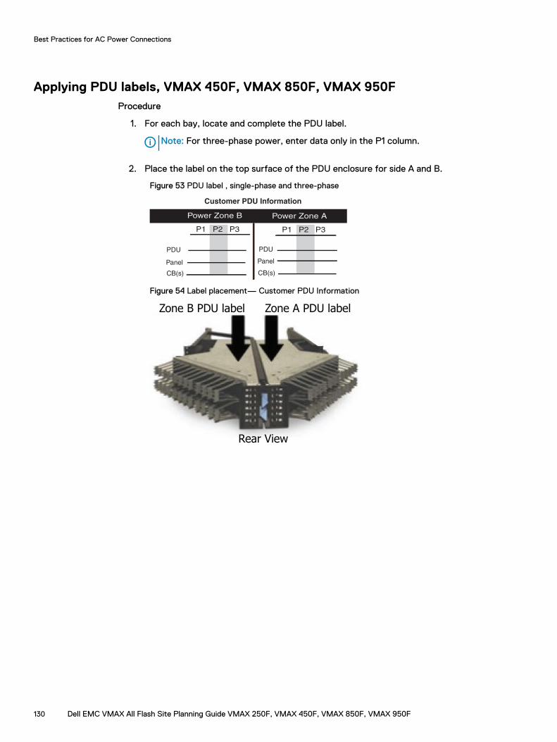
Applying PDU labels, VMAX 450F, VMAX 850F, VMAX 950FProcedure
1. For each bay, locate and complete the PDU label.
Note: For three-phase power, enter data only in the P1 column.
2. Place the label on the top surface of the PDU enclosure for side A and B.
Figure 53 PDU label , single-phase and three-phase
Customer PDU Information
Power Zone B
PDU
Panel
CB(s)
P1 P2 P3
Power Zone A
PDU
Panel
CB(s)
P1 P2 P3
Figure 54 Label placement— Customer PDU Information
Rear View
Zone A PDU labelZone B PDU label
Best Practices for AC Power Connections
130 Dell EMC VMAX All Flash Site Planning Guide VMAX 250F, VMAX 450F, VMAX 850F, VMAX 950F
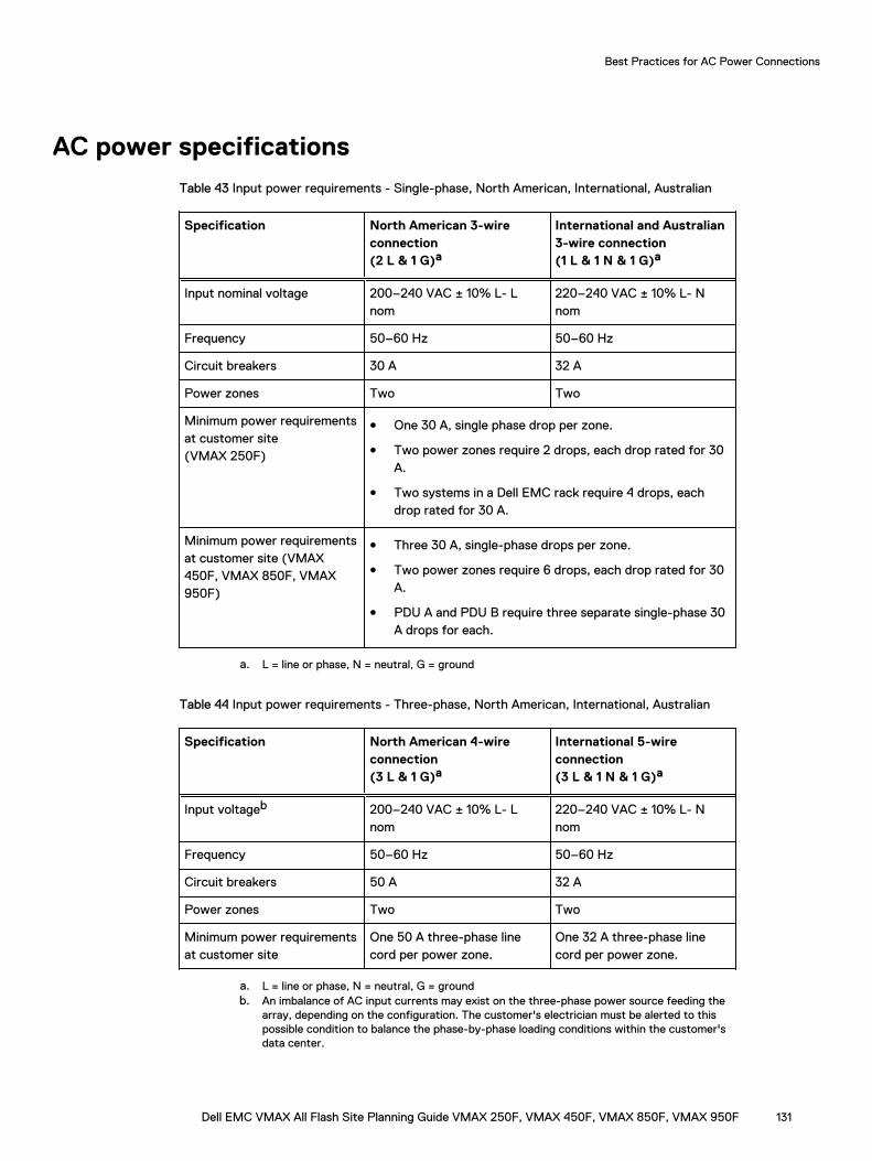
AC power specifications
Table 43 Input power requirements - Single-phase, North American, International, Australian
Specification North American 3-wireconnection(2 L & 1 G)a
International and Australian3-wire connection(1 L & 1 N & 1 G)a
Input nominal voltage 200–240 VAC ± 10% L- Lnom
220–240 VAC ± 10% L- Nnom
Frequency 50–60 Hz 50–60 Hz
Circuit breakers 30 A 32 A
Power zones Two Two
Minimum power requirementsat customer site(VMAX 250F)
l One 30 A, single phase drop per zone.
l Two power zones require 2 drops, each drop rated for 30A.
l Two systems in a Dell EMC rack require 4 drops, eachdrop rated for 30 A.
Minimum power requirementsat customer site (VMAX450F, VMAX 850F, VMAX950F)
l Three 30 A, single-phase drops per zone.
l Two power zones require 6 drops, each drop rated for 30A.
l PDU A and PDU B require three separate single-phase 30A drops for each.
a. L = line or phase, N = neutral, G = ground
Table 44 Input power requirements - Three-phase, North American, International, Australian
Specification North American 4-wireconnection(3 L & 1 G)a
International 5-wireconnection(3 L & 1 N & 1 G)a
Input voltageb 200–240 VAC ± 10% L- Lnom
220–240 VAC ± 10% L- Nnom
Frequency 50–60 Hz 50–60 Hz
Circuit breakers 50 A 32 A
Power zones Two Two
Minimum power requirementsat customer site
One 50 A three-phase linecord per power zone.
One 32 A three-phase linecord per power zone.
a. L = line or phase, N = neutral, G = groundb. An imbalance of AC input currents may exist on the three-phase power source feeding the
array, depending on the configuration. The customer's electrician must be alerted to thispossible condition to balance the phase-by-phase loading conditions within the customer'sdata center.
Best Practices for AC Power Connections
Dell EMC VMAX All Flash Site Planning Guide VMAX 250F, VMAX 450F, VMAX 850F, VMAX 950F 131

Best Practices for AC Power Connections
132 Dell EMC VMAX All Flash Site Planning Guide VMAX 250F, VMAX 450F, VMAX 850F, VMAX 950F