Dell EMC Networking Virtualization Overlay with BGP EVPN · 6 Dell EMC Networking Virtualization...
67
Dell EMC Configuration and Deployment Guide Dell EMC Networking Virtualization Overlay with BGP EVPN Deploying a BGP EPVN leaf-spine topology with VXLAN anycast gateways Abstract This guide covers the deployment of a physical Layer 3 leaf-spine underlay network and Layer 2 virtual network overlays with anycast gateways using VXLAN-based BGP EVPN. May 2019
Transcript of Dell EMC Networking Virtualization Overlay with BGP EVPN · 6 Dell EMC Networking Virtualization...

Dell EMC Configuration and Deployment Guide
Dell EMC Networking Virtualization Overlay with BGP EVPN
Deploying a BGP EPVN leaf-spine topology with VXLAN anycast gateways
Abstract
This guide covers the deployment of a physical Layer 3 leaf-spine
underlay network and Layer 2 virtual network overlays with anycast
gateways using VXLAN-based BGP EVPN.
May 2019

2 Dell EMC Networking Virtualization Overlay with BGP EVPN
Revisions
Date Description
May 2019 Initial release
The information in this publication is provided “as is.” Dell Inc. makes no representations or warranties of any kind with respect to the information in this
publication, and specifically disclaims implied warranties of merchantability or fitness for a particular purpose.
Use, copying, and distribution of any software described in this publication requires an applicable software license.
© 2019 Dell Inc. or its subsidiaries. All Rights Reserved. Dell, EMC, Dell EMC and other trademarks are trademarks of Dell Inc. or its subsidiaries. Other
trademarks may be trademarks of their respective owners.
Dell believes the information in this document is accurate as of its publication date. The information is subject to change without notice.

3 Dell EMC Networking Virtualization Overlay with BGP EVPN
Table of contents
Revisions............................................................................................................................................................................. 2
1 Introduction ................................................................................................................................................................... 6
1.1 Typographical conventions ................................................................................................................................. 6
1.2 Attachments ........................................................................................................................................................ 6
2 Hardware Overview ...................................................................................................................................................... 7
2.1 Dell EMC PowerSwitch S5248F-ON .................................................................................................................. 7
2.2 Dell EMC PowerSwitch S4148U-ON .................................................................................................................. 7
2.3 Dell EMC PowerSwitch Z9264F-ON ................................................................................................................... 8
2.4 Dell EMC PowerSwitch S3048-ON..................................................................................................................... 8
2.5 Dell EMC PowerEdge R740xd server ................................................................................................................ 8
3 BGP EVPN VXLAN overview ....................................................................................................................................... 9
3.1 The VXLAN protocol ......................................................................................................................................... 10
3.2 BGP EVPN VXLAN operation .......................................................................................................................... 11
3.3 Integrated routing and bridging (IRB) ............................................................................................................... 11
3.4 Anycast gateway............................................................................................................................................... 11
3.5 Indirect gateway ................................................................................................................................................ 11
4 Topology ..................................................................................................................................................................... 12
4.1 Leaf-spine underlay .......................................................................................................................................... 12
4.1.1 BGP ASNs and router IDs ................................................................................................................................ 13
4.1.2 Point-to-point IP networks ................................................................................................................................ 13
4.2 Underlay network connections ......................................................................................................................... 15
4.3 BGP EVPN VXLAN overlay .............................................................................................................................. 16
4.4 OOB management network connections .......................................................................................................... 17
5 Switch preparation ...................................................................................................................................................... 19
5.1 Check switch OS version .................................................................................................................................. 19
5.2 Verify license installation .................................................................................................................................. 19
5.3 Factory default configuration ............................................................................................................................ 20
5.4 Configure switch port profile (S4148U-ON only) .............................................................................................. 20
6 Configure leaf switches .............................................................................................................................................. 21
6.1 Initial configuration settings .............................................................................................................................. 21
6.2 VLT configuration.............................................................................................................................................. 22
6.3 Virtual network configuration ............................................................................................................................ 22
6.4 VLAN configuration ........................................................................................................................................... 24
6.5 Downstream interface configuration ................................................................................................................. 25
6.6 Upstream interface configuration ...................................................................................................................... 26

4 Dell EMC Networking Virtualization Overlay with BGP EVPN
6.7 Route map configuration .................................................................................................................................. 26
6.8 Configure UFD in reverse ................................................................................................................................. 27
6.9 BGP configuration............................................................................................................................................. 28
6.10 Static route configuration .................................................................................................................................. 30
7 Configure spine switches ........................................................................................................................................... 31
7.1 Initial configuration settings .............................................................................................................................. 31
7.2 Downstream interface configuration ................................................................................................................. 31
7.3 Route map configuration .................................................................................................................................. 33
7.4 BGP configuration............................................................................................................................................. 33
8 Leaf switch validation ................................................................................................................................................. 37
8.1 General commands .......................................................................................................................................... 37
8.1.1 show interface status ........................................................................................................................................ 37
8.1.2 show vlan .......................................................................................................................................................... 37
8.1.3 show lldp neighbors .......................................................................................................................................... 38
8.1.4 show uplink-state-group id_# detail .................................................................................................................. 38
8.2 VLT validation commands ................................................................................................................................ 39
8.2.1 show vlt domain_id ........................................................................................................................................... 39
8.2.2 show vlt domain_id backup-link ........................................................................................................................ 39
8.2.3 show vlt domain_id mismatch ........................................................................................................................... 39
8.2.4 show vlt domain_id vlt-port-detail ..................................................................................................................... 40
8.3 Routing validation commands .......................................................................................................................... 41
8.3.1 show bfd neighbors .......................................................................................................................................... 41
8.3.2 show ip route .................................................................................................................................................... 41
8.3.3 show ip bgp summary ....................................................................................................................................... 42
8.4 EVPN validation commands ............................................................................................................................. 42
8.4.1 show ip route vrf vrf_name ............................................................................................................................... 42
8.4.2 show evpn evi ................................................................................................................................................... 42
8.4.3 show ip bgp l2vpn evpn summary .................................................................................................................... 43
8.4.4 show ip bgp l2vpn evpn .................................................................................................................................... 43
8.4.5 show evpn mac-ip ............................................................................................................................................. 45
9 Spine switch validation ............................................................................................................................................... 46
9.1 General commands .......................................................................................................................................... 46
9.1.1 show interface status ........................................................................................................................................ 46
9.1.2 show lldp neighbors .......................................................................................................................................... 46
9.2 Routing validation commands .......................................................................................................................... 47
9.2.1 show bfd neighbors .......................................................................................................................................... 47

5 Dell EMC Networking Virtualization Overlay with BGP EVPN
9.2.2 show ip route .................................................................................................................................................... 47
9.2.3 show ip bgp summary ....................................................................................................................................... 48
9.2.4 show ip bgp l2vpn evpn summary .................................................................................................................... 48
10 VMware host and network configuration .................................................................................................................... 49
10.1 VMware ESXi download and installation .......................................................................................................... 49
10.2 Install and configure VMware vCenter Server 6.7 U1 ...................................................................................... 49
10.3 Add ESXi hosts to vCenter Server ................................................................................................................... 49
10.4 Create VMs and install guest operating systems ............................................................................................. 50
10.5 vSphere distributed switches ............................................................................................................................ 51
10.6 Create a VDS .................................................................................................................................................... 51
10.7 Add distributed port groups .............................................................................................................................. 52
10.10 Connect VMs to VDS and port group ............................................................................................................... 56
10.11 Configure networking in the guest OS .............................................................................................................. 57
11 Validate connectivity ................................................................................................................................................... 58
11.1 Validate tunneled Layer 2 bridging ................................................................................................................... 58
11.2 Validate routing using anycast gateways ......................................................................................................... 59
11.3 Validate routing using the indirect gateway ...................................................................................................... 60
A Gateway/firewall switch configuration ........................................................................................................................ 62
A.1 Initial configuration settings .............................................................................................................................. 62
A.2 Indirect gateway configuration .......................................................................................................................... 62
A.3 Simulated external network interface configuration .......................................................................................... 63
A.4 Upstream interfaces ......................................................................................................................................... 63
A.5 Static routes to VNIs ......................................................................................................................................... 63
B Validated components ................................................................................................................................................ 64
B.1 Dell EMC PowerSwitches ................................................................................................................................. 64
B.2 PowerEdge R740xd Servers ............................................................................................................................ 64
B.3 VMware software .............................................................................................................................................. 64
C Technical resources ................................................................................................................................................... 65
C.1 Dell EMC product manuals and technical guides ............................................................................................. 65
C.1 VMware product manuals and technical guides ............................................................................................... 65
D Fabric Design Center ................................................................................................................................................. 66
E Support and feedback ................................................................................................................................................ 67

6 Dell EMC Networking Virtualization Overlay with BGP EVPN
1 Introduction Our vision at Dell EMC is to be the essential infrastructure company from the edge, to the core, and to the
cloud. Dell EMC Networking ensures modernization for today’s applications and for the emerging cloud-native
world. Dell EMC is committed to disrupting the fundamental economics of the market with an open strategy
that gives you the freedom of choice for networking operating systems and top-tier merchant silicon. The Dell
EMC strategy enables business transformations that maximize the benefits of collaborative software and
standards-based hardware, including lowered costs, flexibility, freedom, and security. Dell EMC provides
further customer enablement through validated deployment guides which demonstrate these benefits while
maintaining a high standard of quality, consistency, and support.
This guide provides a step-by-step deployment example of Border Gateway Protocol (BGP) Ethernet Virtual
Private Network (EVPN) for Virtual Extensible LAN (VXLAN) using Dell EMC PowerSwitches and PowerEdge
servers. BGP EVPN for VXLAN is used as a network virtualization overlay to extend Layer 2 connectivity
across the data center, allow for a greatly increased number of Layer 2 domains, and to simplify Virtual
Machine (VM) migration.
The environment includes a physical Layer 3 leaf-spine topology underlay and three overlay virtual networks.
Two virtual networks use anycast gateways, and the third uses an indirect gateway.
VMs running on VMware ESXi hosts are used to validate this environment and to demonstrate tunneling
Layer 2 virtual network traffic through a Layer 3 leaf-spine network. Traffic is sent between VMs on the same
and different virtual networks and to the external network or Internet. The virtual networks using anycast
gateways demonstrate integrated routing and bridging (IRB). The virtual network without an anycast gateway
tunnels through the leaf-spine network to get to the indirect gateway.
1.1 Typographical conventions The CLI and GUI examples in this document use the following conventions:
Monospace Text CLI examples
Underlined Monospace Text CLI examples that wrap the page
Italic Monospace Text Variables in CLI examples
Bold Monospace Text Commands entered at the CLI prompt, or to highlight information in CLI
output
Bold text UI elements and information entered in the GUI
1.2 Attachments This document in .pdf format includes one or more file attachments. To access attachments in Adobe Acrobat
Reader, click the icon in the left pane halfway down the page, then click the icon.

7 Dell EMC Networking Virtualization Overlay with BGP EVPN
2 Hardware Overview This section briefly describes the hardware that is used to validate the deployment examples in this
document. Appendix B contains a complete list of the hardware and software validated for this guide.
Note: While the steps in this document were validated using the specified Dell EMC PowerSwitch models,
they may be leveraged for other Dell EMC PowerSwitch models utilizing the same networking OS version or
later assuming the switch has the available port numbers, speeds, and types.
Leaf switches used in this deployment must support native VXLAN routing, also known as routing in and out
of tunnels (RIOT). As of this writing, this includes S41xx-ON series, S52xx-ON series, S4048T-ON, and
S6010-ON PowerSwitches. See the L3 VXLAN route scaling section of OS10 Enterprise Edition User Guide
Release 10.4.3.0 for more information.
2.1 Dell EMC PowerSwitch S5248F-ON The Dell EMC PowerSwitch S5248F-ON is a 1-Rack Unit (RU), multilayer switch with forty-eight SFP28
25GbE ports, two QSFP28-DD ports (two 100GbE interfaces per port), and four QSFP28 100GbE ports. The
high-performance S5248F-ON switch is an optimal Top-of-rack (ToR) or leaf switch for environments
requiring connectivity for 25GbE and 10GbE compute and storage. This guide uses two S5248F-ONs as leaf
switches.
Dell EMC PowerSwitch S5248F-ON
2.2 Dell EMC PowerSwitch S4148U-ON The Dell EMC PowerSwitch S4148U-ON is a 1-RU, multilayer switch with twenty-four 10GbE ports, two
40GbE ports, four 10/25/40/50/100GbE or FC8/16/32 ports, and twenty-four 10GbE or FC8/16 ports. This
guide uses four S4148U-ONs as leaf switches.
Dell EMC PowerSwitch S4148U-ON

8 Dell EMC Networking Virtualization Overlay with BGP EVPN
2.3 Dell EMC PowerSwitch Z9264F-ON The Dell EMC PowerSwitch Z9264F-ON is a 2-RU, multilayer switch with sixty-four 100GbE ports, or up to
128 10/25/40/50GbE ports using supported breakout cables. This guide uses two Z9264F-ONs as spine
switches.
Dell EMC PowerSwitch Z9264F-ON
2.4 Dell EMC PowerSwitch S3048-ON The Dell EMC PowerSwitch S3048-ON is a 1-RU switch with forty-eight 1GbE BASE-T ports and four 10GbE
SFP+ ports. In this deployment, one S3048-ON is used in each rack for out-of-band (OOB) management
traffic.
Dell EMC PowerSwitch S3048-ON
2.5 Dell EMC PowerEdge R740xd server The Dell EMC PowerEdge R740xd server is a dual socket 2-RU platform that brings scalable storage
performance and data set processing to adapt to a variety of applications. The R740xd server features Intel
Xeon processors, with up to 3 terabytes of expandable memory and a variety of high-performance network
interface options. The server adds extraordinary storage capacity options, making it well-suited for data-
intensive applications that require greater storage, without sacrificing I/O performance. Four R740xd servers
running VMware ESXi are used in this guide.
Dell EMC PowerEdge R740xd server

9 Dell EMC Networking Virtualization Overlay with BGP EVPN
3 BGP EVPN VXLAN overview EVPN is a control plane for VXLAN that is used to reduce flooding in the network and resolve scalability
concerns. EVPN uses multiprotocol BGP (MP-BGP) to exchange information between VXLAN tunnel
endpoints (VTEPs). EVPN was introduced in RFC 7432, and RFC 8365 describes VXLAN-based EVPN.
VXLAN-based EVPN is a next-generation VPN. It is intended to replace previous generation VPNs like Virtual
Private LAN Service (VPLS). Some of its key features are:
• Support for multi-tenancy
• Layer 2 and 3 integrated routing and bridging (IRB)
• Multi-homing
• Minimization of ARP propagation
• MAC mobility (simplified VM migration)
The primary use cases for EVPN are:
• Greatly expanding the potential number of Layer 2 domains
• Service provider multi-tenant hosting
• Data center interconnect (DCI)
SpineSpine
VLT VLT
Server
Server
Server
Server
Gateway/
Firewall
VTEP
VNI A
VTEP VTEP
VLTLeaf Leaf Leaf Leaf Leaf Leaf
VNI B
VNI C
Overlay networks
VNI A GW
VNI B GW
VNI A GW
VNI B GW
VNI A GW
VNI B GW
VNI C GW
VNI A Anycast gateway
VNI B Anycast gateway
VNI C Indirect gateway
Border Leafs
VNI C GW
BGP EVPN topology
This deployment guide demonstrates the following:
• Tunneling of Layer 2 overlay virtual networks through a physical Layer 3 leaf-spine underlay
network using VXLAN-based EVPN
• Decentralized inter-VXLAN routing via anycast gateways for VXLAN Network Identifier (VNI) A
and B
• Centralized routing for VNI C using an indirect gateway located on the external gateway/firewall

10 Dell EMC Networking Virtualization Overlay with BGP EVPN
3.1 The VXLAN protocol VXLAN allows a Layer 2 network to scale across the data center by overlaying an existing Layer 3 network
and is described in Internet Engineering Task Force document RFC 7348. Each overlay is referred to as a
VXLAN segment.
Each segment is identified through a 24-bit segment ID referred to as a VNI. This allows up to 16 Million VNIs,
far more than the traditional 4,094 VLAN IDs allowed on a physical switch.
VXLAN is a tunneling scheme that encapsulates Layer 2 frames in User Datagram Protocol (UDP) segments,
as shown in Figure 7.
VXLAN encapsulated frame
VXLAN encapsulation adds approximately 50 bytes of overhead to each Ethernet frame. As a result, all
switches in the underlay (physical) network must be configured to support an MTU of at least 1600 bytes on
all participating interfaces.
Note: In this deployment example, switch interfaces are set to their maximum supported MTU size of 9216
bytes.
VTEPs handle VXLAN encapsulation and de-encapsulation. In this implementation, the leaf switches are the
VTEPs.
11 Dell EMC Networking Virtualization Overlay with BGP EVPN
3.2 BGP EVPN VXLAN operation EVPN uses BGP to exchange endpoint MAC and IP address information between VTEPs. When a host
sends a packet to an endpoint, the switch looks up the routing table for a match. If it finds a match that exists
behind another VTEP, the packet is encapsulated with VXLAN and UDP headers and encapsulated again
with outer IP and Ethernet headers for transport over the leaf-spine network. When the packet arrives at the
destination VTEP, the outer Ethernet, IP, UDP, and VXLAN headers are removed, and the switch sends the
original packet to the endpoint.
3.3 Integrated routing and bridging (IRB) With EVPN, overlay routing occurs on leaf switches. As of OS10EE version 10.4.3.1, Dell EMC
PowerSwitches support asymmetric IRB. This means that overlay routing, also known as RIOT, occurs on
ingress leaf switches. The packets travel over the leaf and spine network on the destination VNI. When the
packets arrive at the destination VTEP, they are bridged to the endpoint.
3.4 Anycast gateway Anycast gateways with the same IP address are deployed to each leaf pair connected to servers. The anycast
gateway IP address is set as the default gateway for all VMs on that virtual network. VMs on VNIs with
anycast gateways use the same gateway information while behind different leaf pairs. When those VMs
communicate with different networks, their local leaf switches always do the routing. This replaces Virtual
Router Redundancy Protocol (VRRP) and enables VMs to migrate from one leaf pair to another without the
need to change the network configuration.
3.5 Indirect gateway As shown in Figure 6, VNI C does not have an anycast gateway configured. It uses an indirect gateway
attached to the border leafs instead. In this case, the indirect gateway is a physical switch acting as a
firewall/gateway to the Internet. When a VM on VNI C sends a packet destined for another network, it is
tunneled to the border leaf pair where it is forwarded to the indirect gateway which makes the proper
forwarding decisions according to its routing table.
In this deployment example, VNIs A and B also use the indirect gateway to access the Internet by configuring
static routes.

12 Dell EMC Networking Virtualization Overlay with BGP EVPN
4 Topology
4.1 Leaf-spine underlay This deployment uses a Layer 3 leaf-spine topology for the network underlay. The underlay provides transit
for the virtual network overlays.
In a Layer 3 leaf-spine network, traffic between leafs and spines is routed. Equal cost multi-path routing
(ECMP) is used to load balance traffic across the Layer 3 connections. BGP is used to exchange routes. The
Layer 3/Layer 2 (L3/L2) boundary is at the leaf switches.
Two leaf switches are configured as Virtual Link Trunking (VLT) peers at the top of each rack. VLT allows all
connections to be active while also providing fault tolerance. As administrators add racks to the data center,
two leaf switches configured for VLT are added to each new rack. Connections within racks from hosts to leaf
switches are Layer 2, and each host is connected using a VLT port channel.
In this example, two Z9264F-ON switches are used as spines, two S5248F-ON switches are used as leafs in
Rack 1, and four S4148U-ON switches are used as leafs in the remaining two racks. The leafs in the last rack
also act as border leafs.
Note: For this deployment example, any leaf pair may be used as border leafs, and hosts may also be
connected to the border leafs.
For demonstration purposes, there is an additional switch attached to the border leafs which serves as a
simulated gateway/firewall for connections to the external network as shown in Figure 8.
Rack 2Rack 1
S4148U-2bS4148U-2a VLTiS5248F-1bS5248F-1a VLTi
Rack n
S4148U-3bS4148U-3a VLTi
Spine 1 Spine 2Z9264F-1 Z9264F-2
L3 Connection
L3L2
L3L2
Host Host
ECMPL2 Connection
VLT VLT
Gateway/
Firewall
VLT
Border Leafs
Leaf-spine underlay network
Note: Using a leaf-spine network in the data center is considered a best practice. With Z9264F-ON switches
as spines and two leaf switches per rack, this topology will scale to 32 racks. For additional leaf-spine network
information, refer to Dell EMC PowerSwitch Layer 3 Leaf-Spine Deployment and Best Practices with OS10.
There are some BGP configuration differences in this guide to enable the BGP EVPN VXLAN feature.

13 Dell EMC Networking Virtualization Overlay with BGP EVPN
4.1.1 BGP ASNs and router IDs Figure 9 shows the autonomous system numbers (ASNs) and router IDs used for the leaf and spine switches
in this guide. Spine switches share a common ASN and each pair of leaf switches shares a common ASN.
ASNs should follow a logical pattern for ease of administration and allow for growth as switches are added.
Using private ASNs in the data center is a best practice. Private, 2-byte ASNs range from 64512 through
65534.
In this example, 65101 is used on both switches at the spine layer. Leaf switches use ASNs with a "2" in the
hundreds place, 65201 for example, and the last digit is used to uniquely identify the leaf pair. Additional
spine switches would be assigned the existing ASN for the spine layer, 65101. Additional leaf switches would
be added in pairs with the next pair assigned an ASN of 65204.
The IP addresses shown are loopback addresses used as BGP router IDs and for BGP EVPN peering.
Loopback addresses should follow a logical pattern to make it easier to manage and allow for growth. In this
example, the 10.2.0.0/16 IP address space is used. The third octet in the address represents the layer, “1” for
spine and “2” for leaf, and the fourth octet is the counter for the appropriate layer
AS65202AS65201
10.2.2.410.2.2.3 VLTi10.2.2.210.2.2.1 VLTi
AS65203
10.2.2.610.2.2.5 VLTi
Spine 1 Spine 210.2.1.1 10.2.1.2
AS 65101
BGP ASNs and router IDs
4.1.2 Point-to-point IP networks Establishing a logical, scalable IP address scheme is important before deploying a leaf-spine topology. The
point-to-point links used in this deployment are labeled A-O in Figure 10.
Rack 2Rack 1
Leaf 2bLeaf 2a VLTiLeaf 1bLeaf 1a VLTi
Rack n
Leaf 3bLeaf 3a VLTi
Spine 1 Spine 2Spine 1 Spine 2
BA FEDC G IH J K L
M N O
Point-to-point networks

14 Dell EMC Networking Virtualization Overlay with BGP EVPN
Each link is a separate, point-to-point IP network. Table 1 details the links labeled in Figure 10. The IP
addresses in the table are used in the switch configuration examples.
Point-to-point network IP addresses
Link
label
Source
switch
Source IP
address
Destination
switch
Destination IP
address Network
A Spine 1 192.168.1.0 Leaf 1a 192.168.1.1 192.168.1.0/31
B Spine 2 192.168.2.0 Leaf 1a 192.168.2.1 192.168.2.0/31
C Spine 1 192.168.1.2 Leaf 1b 192.168.1.3 192.168.1.2/31
D Spine 2 192.168.2.2 Leaf 1b 192.168.2.3 192.168.2.2/31
E Spine 1 192.168.1.4 Leaf 2a 192.168.1.5 192.168.1.4/31
F Spine 2 192.168.2.4 Leaf 2a 192.168.2.5 192.168.2.4/31
G Spine 1 192.168.1.6 Leaf 2b 192.168.1.7 192.168.1.6/31
H Spine 2 192.168.2.6 Leaf 2b 192.168.2.7 192.168.2.6/31
I Spine 1 192.168.1.8 Leaf 3a 192.168.1.9 192.168.1.8/31
J Spine 2 192.168.2.8 Leaf 3a 192.168.2.9 192.168.2.8/31
K Spine 1 192.168.1.10 Leaf 3b 192.168.1.11 192.168.1.10/31
L Spine 2 192.168.2.10 Leaf 3b 192.168.2.11 192.168.2.10/31
M Leaf 1a 192.168.3.0 Leaf 1b 192.168.3.1 192.168.3.0/31
N Leaf 2a 192.168.3.2 Leaf 2b 192.168.3.3 192.168.3.2/31
O Leaf 3a 192.168.3.4 Leaf 3b 192.168.3.5 192.168.3.4/31
Note: As with all examples in this guide, any valid IP address scheme can be used. The example point-to-
point addresses above use a 31-bit mask to save address space. This is optional and covered in RFC 3021.

15 Dell EMC Networking Virtualization Overlay with BGP EVPN
4.2 Underlay network connections The physical underlay network connections are shown in Figure 11. Each leaf has one connection to each
spine. 100GbE uplink ports on leafs are used to maximize bandwidth. Each host has one connection to each
leaf configured as an LACP port channel on the host and as a VLT port channel on the two leafs. Connections
from hosts to S5248F-ON leaf switches are 25GbE. Connections from hosts to S4148U-ON leaf switches are
10GbE (not shown).
GR
N=10G
ACT/LN
K A
GR
N=10G
ACT/LN
K B
S5248F-ON
Leaf 1A
S5248F-ON
Leaf 1B
PowerEdge
R740xd
Stack ID
Reset
Stack ID
Reset
Z9264F-ON
Spine 1
Z9264F-ON
Spine 2
Stack ID
Stack ID
25GbE Layer 2 link
100GbE VLTi link
100GbE Layer 3 link (Spine 1)
100GbE Layer 3 link (Spine 2)
VLT port channel
VLTi
Production network connections
Note: Optionally, the two QSFP28-DD double density ports (2x100GbE interfaces per physical port), available
on S5248F-ON switches, may be used for the VLTi instead of the QSFP28 ports (1x100GbE interface per
physical port). This requires two QSFP28-DD DAC cables. However, QSFP28-DD ports are not available on
S4148U-ONs also used as leaf switches in this guide. For this deployment example, all six leafs use two
QSFP28 ports per switch for the VLTi.

16 Dell EMC Networking Virtualization Overlay with BGP EVPN
4.3 BGP EVPN VXLAN overlay
Rack n
R740xd-1
R740xd-2
R740xd-3
R740xd-4
ECMP
Gateway/
Firewall
S5248F-1a S5248F-1b S4148U-2a S4148U-2b S4148U-3a S4148U-3b
VNI 1614
172.16.14.253
172.16.15.253
172.16.14.253
172.16.15.253
172.16.16.253
VTEP 10.222.222.1
Border leafs
eBGP
eBGP
Rack 1 Rack 2
VNI 1614 VNI 1616
VRF tenant1
VLTi VLTi VLTi
VLT
Z9264F-1 Z9264F-2
VLTVLT
VM
VM
VM VMVM
VMVM VM
Physical L3 connection
Physical L2 connection
Virtual L2 connection
Virtual L2 connection
Virtual L2 connection
VM
VM
VM VM on VNI 1614, IP 172.16.14.x /24
VM on VNI 1615, IP 172.16.15.x /24
VM on VNI 1616, IP 172.16.16.x /24
172.16.15.253
172.16.16.253
Anycast gateway - VNI 1614
Anycast gateway - VNI 1615
Indirect gateway - VNI 1616
172.16.14.253
VNI 1615
VTEP 10.222.222.2
VTEP 10.222.222.3
BGP EVPN topology with anycast gateways and an indirect gateway
In this deployment example, three VNIs are used: 1614, 1615, and 1616. All VNIs are configured all on six
leaf switches. However, only VNIs 1614 and 1615 are configured with anycast gateways. Because these VNIs
have anycast gateways, VMs on those VNIs which are routing to other networks can use the same gateway
information while behind different leaf pairs. When those VMs route, their local leaf switches will always be
doing the routing. This replaces VRRP and enables VMs to migrate from one leaf pair to another without the
need to change the network configuration. It also eliminates hairpinning and improves link utilization since
routing is performed much closer to the source.
This topology also uses a traditional centralized gateway for routing to external networks, such as the
Internet. VNI 1616 does not have anycast gateways configured, and VMs on this VNI use the physical
gateway/firewall switch as their default gateway. When VMs on VNI 1616 send packets to another VNI or
Internet destination, their packets are tunneled to the third leaf pair where their VXLAN information is stripped
off, and the original frame is exposed. The destination MAC address matches the gateway/firewall and is
forwarded according to its routing table.
With the addition of static routes, VMs with anycast gateways also use the indirect gateway to communicate
with external networks or VMs on VNI 1616. In this example, default routes are installed on all leaf switches
pointing to the indirect gateway. This way, a VM on VNI 1614, for instance, can get the benefit of anycast
gateways, while also being able to access resources made available via the indirect gateway. Static routes
are also used at the indirect gateway to route traffic from external networks or VNI 1616 back to VNIs 1614
and 1615.
Note: VNIs can any number be in the range 1-16777215.

17 Dell EMC Networking Virtualization Overlay with BGP EVPN
4.4 OOB management network connections The OOB management network is an isolated network for remote management of servers, switches, and
other devices. It is also used to carry heartbeat messages sent between leaf switches configured as VLT
peers.
Dell EMC recommends using at least one S3048-ON switch per 42-RU rack for OOB management network
connections. Each S3048-ON has forty-eight 1GbE Base-T ports for connections to server iDRACs and
switch management ports. In this deployment, each server has an additional 1GbE OOB management
connection for ESXi host management as shown in Figure 13.
17 18 19 20 21 22 23 24 25 26 27 28 29 30 31 321 2 3 4 5 6 7 8 9 10 11 12 13 14 15 16 33 34 35 36 37 38 39 40 41 42 43 44 45 46 47 48 51 5249 50
GRN
=10G
ACT/LN
K A
GRN
=10G
ACT/LN
K B
S5248F-ON
Leaf 1A
S5248F-ON
Leaf 1B
R740xd
S3048-ON
OOB management
Stack ID
Reset
Stack ID
Reset
1GbE OOB management link
Z9264F-ON
Spine 1
Z9264F-ON
Spine 2
OOB management network connections

18 Dell EMC Networking Virtualization Overlay with BGP EVPN
Four 10GbE SFP+ ports are available on the S3048-ON for uplinks to the OOB management network core
(links not shown).
Note: When running OS10EE, the S3048-ON will function as an OOB management switch with its factory
default settings, or it may be configured as needed for your environment. By default, all ports are in switchport
mode, in VLAN 1, administratively up, and rapid per-VLAN spanning tree plus (RPVST+) is enabled. At a
minimum, Dell EMC recommends changing the admin password to a complex password during the first login.

19 Dell EMC Networking Virtualization Overlay with BGP EVPN
5 Switch preparation
5.1 Check switch OS version Dell EMC PowerSwitches must be running OS10EE version 10.4.3.1 or later for this deployment.
Run the show version command to check the OS version. Dell EMC recommends upgrading to the latest
release available on Dell Digital Locker (account required).
OS10# show version
Dell EMC Networking OS10-Enterprise
Copyright (c) 1999-2019 by Dell Inc. All Rights Reserved.
OS Version: 10.4.3.1
Build Version: 10.4.3.1.154
Note: For information on installing and upgrading OS10EE, see the Dell EMC Networking OS10 Enterprise
Edition Quick Start Guide.
5.2 Verify license installation Run the command show license status to verify license installation. The License Type: field should
indicate PERPETUAL as shown in bold below. If an evaluation license is installed, licenses purchased from
Dell EMC are available for download on Dell Digital Locker. Installation instructions are provided in the OS10
Enterprise Edition User Guide Release 10.4.3.0
OS10# show license status
System Information
---------------------------------------------------------
Vendor Name : Dell EMC
Product Name : S5248F-ON
Hardware Version : A01
Platform Name : x86_64-dellemc_s5248f_c3538-r0
PPID : CN046MRJCES0089K0004
Service Tag : 68X00Q2
Product Base :
Product Serial Number:
Product Part Number :
License Details
----------------
Software : OS10-Enterprise
Version : 10.4.3.1
License Type : PERPETUAL
License Duration: Unlimited
License Status : Active
License location: /mnt/license/68X00Q2.lic
---------------------------------------------------------
Note: If OS10EE was factory installed, a perpetual license is already on the switch.

20 Dell EMC Networking Virtualization Overlay with BGP EVPN
5.3 Factory default configuration The switch configuration commands in the chapters that follow begin with the leaf switches at their factory
default settings. Dell EMC PowerSwitches running OS10EE can be reset to their default configuration as
follows:
OS10# delete startup-configuration
Proceed to delete startup-configuration [confirm yes/no(default)]:y
OS10# reload
System configuration has been modified. Save? [yes/no]:n
Proceed to reboot the system? [confirm yes/no]:y
The switch reboots to its factory default configuration.
Note: OS10EE at its default settings has Telnet disabled, SSH enabled, and the OOB management interface
configured to get its IP address via DHCP. The default username and password are both admin. Dell EMC
recommends changing the admin password to a complex password during the first login.
5.4 Configure switch port profile (S4148U-ON only)
Note: This section is specific to the S4148U-ON switches used as examples in this guide. Port profiles are
currently supported on the S4148-ON series of switches and S4148U-ON switches. Disregard this section for
other models. See the Switch-port profiles section of OS10 Enterprise Edition User Guide Release 10.4.3.0
for switch-port profile options and details.
Four S4148U-ON switches are used as leafs in this deployment example. A switch port profile determines the
enabled front-panel ports and supported breakout modes on Ethernet and unified ports. Switch port profile-3
is used in this deployment example to enable four 100GbE ports (two for uplinks to the spines and two for the
VLTi) on each S4148U-ON switch.
To change the switch port profile from its default setting to profile-3, run the following commands:
OS10# configure terminal
OS10(config)# switch-port-profile 1/1 profile-3
Warning: Switch port profile will be applied only after a save and reload.
All management port configurations will be retained but all other
configurations will be wiped out after the reload.
OS10(config)# exit
OS10# write memory
OS10# reload
Proceed to reboot the system? [confirm yes/no]:y

21 Dell EMC Networking Virtualization Overlay with BGP EVPN
6 Configure leaf switches
Note: This deployment uses six leaf switches. All six leaf switch configuration files are provided as annotated
text file attachments to this .pdf. Section 1.2 describes how to access .pdf attachments.
This chapter details the configuration commands issued to the first two leaf switches, Leaf1a and Leaf1b.
Configuration differences for Leafs 2a, 2b, 3a, and 3b are noted below the command tables. The commands
should be entered in the order shown.
Note: All switches start at their factory default settings per Section 5.3. After setting to factory defaults,
S4148U-ON switches are set to switch-port-profile 3 as described in Section 5.4.
The leaf switch configuration includes the physical underlay network between the servers and spines and the
virtual network configuration which enables the overlay networks between all switches.
6.1 Initial configuration settings 1. Enter configuration mode with the configure terminal command.
2. Configure the hostname.
3. If DHCP is not used, configure the OOB management IP address and default gateway.
4. Enable spanning tree protocol as a precaution against loops. Any spanning tree protocol type
supported by the switch is acceptable. This example uses RSTP. The first leaf in the pair is
configured as the primary RSTP root bridge using the spanning-tree rstp priority 0
command and the second leaf as the secondary RSTP root bridge using the spanning-tree rstp
priority 4096 command.
5. Optionally, set the hardware overlay routing profile to scaled-overlay-routing. This allocates
more switch hardware resources to virtual networking. See the L3 VXLAN route scaling section of the
OS10 Enterprise Edition User Guide Release 10.4.3.0 for more information.
6. Enable Bidirectional Forwarding Detection (BFD).
7. Create a VRF named tenant1.
Initial configuration settings
Leaf1a Leaf1b
configure terminal
hostname Leaf1a
interface mgmt 1/1/1
no ip address
ip address 100.67.166.219/24
no shutdown
management route 0.0.0.0/0
100.67.166.254
spanning-tree mode rstp
spanning-tree rstp priority 0
hardware overlay-routing-profile
scaled-overlay-routing
bfd enable
ip vrf tenant1
configure terminal
hostname Leaf1b
interface mgmt 1/1/1
no ip address
ip address 100.67.166.220/24
no shutdown
management route 0.0.0.0/0
100.67.166.254
spanning-tree mode rstp
spanning-tree rstp priority 4096
hardware overlay-routing-profile
scaled-overlay-routing
bfd enable
ip vrf tenant1

22 Dell EMC Networking Virtualization Overlay with BGP EVPN
Leaf1a Leaf1b
exit exit
Note: The remaining leaf switches are configured in the same manner.
6.2 VLT configuration 1. Give the two interfaces used in the VLTi a description and remove them from Layer 2 mode with the
no switchport command.
2. Create the VLT domain. Use the same value on both peers.
3. Add the backup destination address. This is the management IP address of the VLT peer switch.
4. Set the VLT delay restore timer to 120. Dell EMC recommends increasing the restore timer in an
EVPN configuration from its default value, 90, to allow for BGP EVPN adjacency to be established
and for the remote MAC and neighbor entries to be downloaded by EVPN.
5. Add the interfaces participating in VLTi with the discovery-interface command.
6. Specify a VLT MAC address. Use the same value on both peers.
VLT configuration
Leaf1a Leaf1b
interface range ethernet 1/1/55-1/1/56
description VLTi
no switchport
vlt-domain 127
backup destination 100.67.166.220
delay-restore 120
discovery-interface ethernet 1/1/55
discovery-interface ethernet 1/1/56
vlt-mac 00:00:01:02:03:01
interface range ethernet 1/1/55-1/1/56
description VLTi
no switchport
vlt-domain 127
backup destination 100.67.166.219
delay-restore 120
discovery-interface ethernet 1/1/55
discovery-interface ethernet 1/1/56
vlt-mac 00:00:01:02:03:01
Note: The remaining leaf switches are configured in the same manner. Dell EMC recommends using at least
two high-bandwidth ports for the VLTi. Port numbers used will vary depending on switch model.
6.3 Virtual network configuration 1. Create interface loopback0 and give it a description and IP address. This will be used for the VTEP.
Use the same IP address on both leafs.
2. Create interface loopback1 and give it a description and IP address. This will be the router ID used for
the BGP adjacency carrying the EVPN overlay routes. Use a unique IP address on each leaf.
3. Create a Network Virtualization Edge (NVE) instance with the nve command and specify loopback0
as the designated VTEP source interface.
4. Enable the EVPN control plane with the evpn command. For each VNI:
a. Create an EVPN instance (EVI).
b. Map a VNI to the EVI. The BGP EVPN protocol groups MAC addresses and ARP/neighbor
addresses under EVIs to exchange them between VTEPs. In OS10, each EVI is associated with
a VNI in a 1:1 mapping.
c. Configure a Route Distinguisher (RD) using the format 4-octet-ipv4addr:2-octet-number.
This example uses the format vtep-ip-address:evi.

23 Dell EMC Networking Virtualization Overlay with BGP EVPN
d. Configure a Route Target (RT). This example uses the format evi:evi and the route target
type, import/export/both, is set to both.
5. For each VNI, 1614-1616, configure a virtual network interface as follows:
a. Assign each to VRF tenant1.
b. Configure each with an IP address.
6. A virtual router IP address if configured on VNI 1614 and VNI 1615 only. In this example, VNI 1616
uses an indirect gateway and does not use a virtual router address.
7. Configure the anycast gateway MAC address using the ip virtual-router mac-address
command. The same MAC address is used for all VTEPs.
8. Map each virtual network to its corresponding VNI.
Virtual network configuration
Leaf1a Leaf1b
interface loopback0
description "VTEP address"
no shutdown
ip address 10.222.222.1/32
interface loopback1
description "Router ID"
no shutdown
ip address 10.2.2.1/32
nve
source-interface loopback0
evpn
evi 1614
vni 1614
rd 10.222.222.1:1614
route-target 1614:1614 both
evi 1615
vni 1615
rd 10.222.222.1:1615
route-target 1615:1615 both
evi 1616
vni 1616
rd 10.222.222.1:1616
route-target 1616:1616 both
interface virtual-network 1614
ip vrf forwarding tenant1
ip address 172.16.14.241/24
ip virtual-router address
172.16.14.253
interface virtual-network 1615
ip vrf forwarding tenant1
ip address 172.16.15.241/24
interface loopback0
description "VTEP address"
no shutdown
ip address 10.222.222.1/32
interface loopback1
description "Router ID"
no shutdown
ip address 10.2.2.2/32
nve
source-interface loopback0
evpn
evi 1614
vni 1614
rd 10.222.222.1:1614
route-target 1614:1614 both
evi 1615
vni 1615
rd 10.222.222.1:1615
route-target 1615:1615 both
evi 1616
vni 1616
rd 10.222.222.1:1616
route-target 1616:1616 both
interface virtual-network 1614
ip vrf forwarding tenant1
ip address 172.16.14.242/24
ip virtual-router address
172.16.14.253
interface virtual-network 1615
ip vrf forwarding tenant1
ip address 172.16.15.242/24
24 Dell EMC Networking Virtualization Overlay with BGP EVPN
Leaf1a Leaf1b
ip virtual-router address
172.16.15.253
interface virtual-network 1616
ip vrf forwarding tenant1
ip address 172.16.16.241/24
exit
ip virtual-router mac-address
00:01:01:01:01:01
virtual-network 1614
vxlan-vni 1614
virtual-network 1615
vxlan-vni 1615
virtual-network 1616
vxlan-vni 1616
ip virtual-router address
172.16.15.253
interface virtual-network 1616
ip vrf forwarding tenant1
ip address 172.16.16.242/24
exit
ip virtual-router mac-address
00:01:01:01:01:01
virtual-network 1614
vxlan-vni 1614
virtual-network 1615
vxlan-vni 1615
virtual-network 1616
vxlan-vni 1616
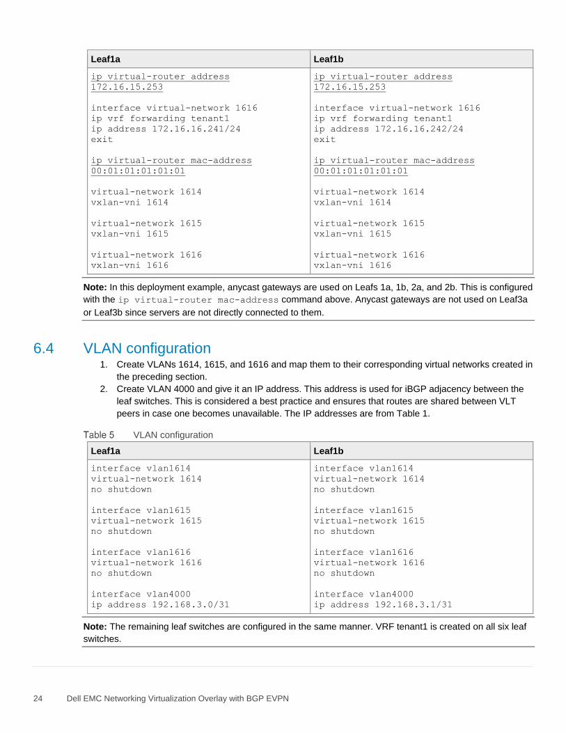
Note: In this deployment example, anycast gateways are used on Leafs 1a, 1b, 2a, and 2b. This is configured
with the ip virtual-router mac-address command above. Anycast gateways are not used on Leaf3a
or Leaf3b since servers are not directly connected to them.
6.4 VLAN configuration 1. Create VLANs 1614, 1615, and 1616 and map them to their corresponding virtual networks created in
the preceding section.
2. Create VLAN 4000 and give it an IP address. This address is used for iBGP adjacency between the
leaf switches. This is considered a best practice and ensures that routes are shared between VLT
peers in case one becomes unavailable. The IP addresses are from Table 1.
VLAN configuration
Leaf1a Leaf1b
interface vlan1614
virtual-network 1614
no shutdown
interface vlan1615
virtual-network 1615
no shutdown
interface vlan1616
virtual-network 1616
no shutdown
interface vlan4000
ip address 192.168.3.0/31
interface vlan1614
virtual-network 1614
no shutdown
interface vlan1615
virtual-network 1615
no shutdown
interface vlan1616
virtual-network 1616
no shutdown
interface vlan4000
ip address 192.168.3.1/31
Note: The remaining leaf switches are configured in the same manner. VRF tenant1 is created on all six leaf
switches.

25 Dell EMC Networking Virtualization Overlay with BGP EVPN
6.5 Downstream interface configuration Each downstream (server-connected) interface is configured as follows.
1. Create server-connected port channels. In this example, port channel 100 is connected to Server 1,
and port channel 101 is connected to Server 2.
a. Give the port channel a description.
b. Use the switchport mode trunk command to enable the port channel to carry traffic for
multiple VLANs.
c. Allow tagged VLANs 1614 through 1616 on the trunked port channel.
d. Configure the port channel as an STP edge port.
e. Specify that the port channel is a VLT port channel.
f. Set the MTU to 9216 bytes to allow jumbo frames on the port channel.
2. Configure the port-channel members.
a. Give the physical interface a description.
b. Add the physical interface to the appropriate port channel.
Downstream interfaces
Leaf1a Leaf1b
interface port-channel 100
description "Server 1"
switchport mode trunk
switchport trunk allowed vlan 1614-
1616
spanning-tree port type edge
vlt-port-channel 100
mtu 9216
interface port-channel 101
description "Server 2"
switchport mode trunk
switchport trunk allowed vlan 1614-
1616
spanning-tree port type edge
vlt-port-channel 101
mtu 9216
interface ethernet 1/1/31
description "Server 1"
channel-group 100 mode active
interface ethernet 1/1/32
description "Server 2"
channel-group 101 mode active
Note: Leaf switches 2a and 2b are configured in the same manner, with VLT port channels going to Server 3
and Server 4. Leaf switches 3a and 3b are connected to the switch acting as an external gateway/firewall via
a single VLT port channel.

26 Dell EMC Networking Virtualization Overlay with BGP EVPN
6.6 Upstream interface configuration Each upstream (spine-connected) interface is configured as follows:
1. Provide an interface description.
2. Put each interface into Layer 3 mode by running the no switchport command and assigning an IP
address per Table 1.
3. Set the MTU to 9216 bytes to allow jumbo frames.
Upstream interfaces
Leaf1a Leaf1b
interface ethernet 1/1/53
description "Spine1 eth 1/1/1"
no switchport
ip address 192.168.1.1/31
mtu 9216
no shutdown
interface ethernet 1/1/54
description "Spine2 eth 1/1/1
no switchport
ip address 192.168.2.1/31
mtu 9216
no shutdown
interface ethernet 1/1/53
description "Spine1 eth 1/1/2"
no switchport
ip address 192.168.1.3/31
mtu 9216
no shutdown
interface ethernet 1/1/54
description "Spine2 eth 1/1/2"
no switchport
ip address 192.168.2.3/31
mtu 9216
no shutdown
Note: The remaining leaf switches are configured in the same manner. S4148U-ON leaf switches use
different ports, ethernet 1/1/25-1/1/26, for the 100GbE connections to the spines.
6.7 Route map configuration In this section, a route map is configured to redistribute all loopback addresses used as router IDs and VTEP
addresses via BGP.
1. Configure a route map named spine-leaf.
2. Set the route map to match the IP prefix list items named spine-leaf.
3. Configure two IP prefix list items:
a. The prefix list that specifies 10.2.2.0/24 ge 32 includes all addresses in the 10.2.2.0/24
address range with a mask greater than or equal to 32. This range includes all leaf router IDs.
b. The prefix list that specifies 10.222.222.0/24 ge 32 includes all addresses in the
10.222.222.0/24 address range with a mask greater than or equal to 32. This range includes all
VTEP IP addresses.
27 Dell EMC Networking Virtualization Overlay with BGP EVPN
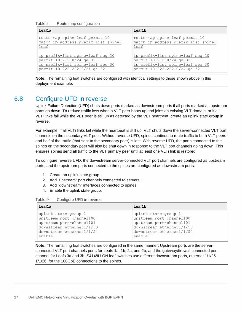
Route map configuration
Leaf1a Leaf1b
route-map spine-leaf permit 10
match ip address prefix-list spine-
leaf
ip prefix-list spine-leaf seq 20
permit 10.2.2.0/24 ge 32
ip prefix-list spine-leaf seq 30
permit 10.222.222.0/24 ge 32
route-map spine-leaf permit 10
match ip address prefix-list spine-
leaf
ip prefix-list spine-leaf seq 20
permit 10.2.2.0/24 ge 32
ip prefix-list spine-leaf seq 30
permit 10.222.222.0/24 ge 32
Note: The remaining leaf switches are configured with identical settings to those shown above in this
deployment example.
6.8 Configure UFD in reverse Uplink Failure Detection (UFD) shuts down ports marked as downstream ports if all ports marked as upstream
ports go down. To reduce traffic loss when a VLT peer boots up and joins an existing VLT domain, or if all
VLTi links fail while the VLT peer is still up as detected by the VLT heartbeat, create an uplink state group in
reverse.
For example, if all VLTi links fail while the heartbeat is still up, VLT shuts down the server-connected VLT port
channels on the secondary VLT peer. Without reverse UFD, spines continue to route traffic to both VLT peers
and half of the traffic (that sent to the secondary peer) is lost. With reverse UFD, the ports connected to the
spines on the secondary peer will also be shut down in response to the VLT port channels going down. This
ensures spines send all traffic to the VLT primary peer until at least one VLTi link is restored.
To configure reverse UFD, the downstream server-connected VLT port channels are configured as upstream
ports, and the upstream ports connected to the spines are configured as downstream ports.
1. Create an uplink state group.
2. Add "upstream" port channels connected to servers.
3. Add "downstream" interfaces connected to spines.
4. Enable the uplink state group.
Configure UFD in reverse
Leaf1a Leaf1b
uplink-state-group 1
upstream port-channel100
upstream port-channel101
downstream ethernet1/1/53
downstream ethernet1/1/54
enable
uplink-state-group 1
upstream port-channel100
upstream port-channel101
downstream ethernet1/1/53
downstream ethernet1/1/54
enable
Note: The remaining leaf switches are configured in the same manner. Upstream ports are the server-
connected VLT port channels ports for Leafs 1a, 1b, 2a, and 2b, and the gateway/firewall connected port
channel for Leafs 3a and 3b. S4148U-ON leaf switches use different downstream ports, ethernet 1/1/25-
1/1/26, for the 100GbE connections to the spines.

28 Dell EMC Networking Virtualization Overlay with BGP EVPN
6.9 BGP configuration
Note: AS and router ID numbers used in this section are from Figure 9. IP addresses are from Table 1.
1. Start BGP configuration with the router bgp AS_number command.
2. Enable BFD, specify BFD timers, and enable the BFD active role.
3. Specify to redistribute loopback routes into BGP for the IPv4 unicast address family.
4. Enable ECMP with the bestpath as-path multipath-relax command.
5. Set the eBGP maximum paths to 2 since there are two paths (one through each spine switch).
6. Enable graceful restart.
7. Configure the neighbors that share routes to the VTEPs:
a. Specify the neighbor by its link IP address per Table 1.
b. Set the advertisement interval.
c. Enable BFD.
d. Enable fall-over.
e. Specify the remote autonomous system number.
f. Specify the IPv4 unicast address family.
8. Configure the neighbors that share control plane information via EVPN instances:
a. Specify the neighbor by its router ID number per Figure 9.
b. Allow up to two hops with the ebgp-multihop command.
c. Specify the remote autonomous system number.
d. Enable extended communities.
e. Specify loopback1 for establishing the BGP sessions.
f. Disable the IPv4 unicast address family and activate the EVPN address family.
9. Configure the VLT leaf peer as an iBGP neighbor.
a. Specify the neighbor by its link IP address per Table 1.
b. Specify the remote autonomous system number.
BGP Configuration
Leaf1a Leaf1b
router bgp 65201
bfd all-neighbors interval 200 min_rx
200 multiplier 3 role active
address-family ipv4 unicast
redistribute connected route-map
spine-leaf
bestpath as-path multipath-relax
maximum-paths ebgp 2
graceful-restart role receiver-only
neighbor 192.168.1.0
advertisement-interval 5
bfd
fall-over
remote-as 65101
address-family ipv4 unicast
router bgp 65201
bfd all-neighbors interval 200 min_rx
200 multiplier 3 role active
address-family ipv4 unicast
redistribute connected route-map
spine-leaf
bestpath as-path multipath-relax
maximum-paths ebgp 2
graceful-restart role receiver-only
neighbor 192.168.1.2
advertisement-interval 5
bfd
fall-over
remote-as 65101
address-family ipv4 unicast

29 Dell EMC Networking Virtualization Overlay with BGP EVPN
Leaf1a Leaf1b
no shutdown
neighbor 192.168.2.0
advertisement-interval 5
bfd
fall-over
remote-as 65101
address-family ipv4 unicast
no shutdown
neighbor 10.2.1.1
ebgp-multihop 2
remote-as 65101
send-community extended
update-source loopback1
no shutdown
address-family ipv4 unicast
no activate
address-family l2vpn evpn
activate
neighbor 10.2.1.2
ebgp-multihop 2
remote-as 65101
send-community extended
update-source loopback1
no shutdown
address-family ipv4 unicast
no activate
address-family l2vpn evpn
activate
neighbor 192.168.3.1
remote-as 65201
no shutdown
no shutdown
neighbor 192.168.2.2
advertisement-interval 5
bfd
fall-over
remote-as 65101
address-family ipv4 unicast
no shutdown
neighbor 10.2.1.1
ebgp-multihop 2
remote-as 65101
send-community extended
update-source loopback1
no shutdown
address-family ipv4 unicast
no activate
address-family l2vpn evpn
activate
neighbor 10.2.1.2
ebgp-multihop 2
remote-as 65101
send-community extended
update-source loopback1
no shutdown
address-family ipv4 unicast
no activate
address-family l2vpn evpn
activate
neighbor 192.168.3.0
remote-as 65201
no shutdown
Note: The remaining leaf switches are configured in the same manner. AS numbering and IP addressing is
done per Figure 9 and Table 1.

30 Dell EMC Networking Virtualization Overlay with BGP EVPN
6.10 Static route configuration 1. A default static route which points to the gateway/firewall switch is configured on all leaf switches so
that VMs on VNIs 1614 and 1615 can access the Internet.
2. When the configuration is complete, exit configuration mode and save the configuration with the end
and write memory commands.
Note: Static routes to VNIs 1614 and 1615 are also configured on the gateway/firewall switch, so it can
properly route return traffic to the VMs. The gateway/firewall switch configuration is detailed in Appendix A
and attached as a text file attachment to this .pdf. Section 1.2 describes how to access .pdf attachments.
Static route configuration
Leaf1a Leaf1b
ip route vrf tenant1 0.0.0.0/0
172.16.16.253
end
write memory
ip route vrf tenant1 0.0.0.0/0
172.16.16.253
end
write memory
Note: The remaining leaf switches are configured with identical settings to those shown above in this
deployment example.

31 Dell EMC Networking Virtualization Overlay with BGP EVPN
7 Configure spine switches This chapter details the configuration commands issued to the two Z9264F-ON spine switches, Spine1 and
Spine2. The switches start at their factory default settings per Section 5.3. The commands in the sections that
follow should be entered in the order shown.
Note: Both spine switch configuration files are provided as text file attachments to this .pdf. Section 1.2
describes how to access .pdf attachments.
The configuration of the spines consists of interface configuration and BGP configuration.
7.1 Initial configuration settings 1. Enter configuration mode with the configure terminal command.
2. Configure the hostname.
3. If DHCP is not used, configure the OOB management IP address and default gateway.
4. Enable spanning tree protocol as a precaution against loops. Any spanning tree protocol type
supported by the switch is acceptable. This example uses RSTP.
5. Enable BFD.
Initial configuration settings
Spine1 Spine2
configure terminal
hostname Spine1
interface mgmt 1/1/1
no ip address
ip address 100.67.166.237/24
no shutdown
management route 0.0.0.0/0
100.67.166.254
spanning-tree mode rstp
bfd enable
configure terminal
hostname Spine2
interface mgmt 1/1/1
no ip address
ip address 100.67.166.233/24
no shutdown
management route 0.0.0.0/0
100.67.166.254
spanning-tree mode rstp
bfd enable
7.2 Downstream interface configuration In this section, the six point-to-point interfaces to the Leaf switches downstream are configured, and the router
ID is assigned.
1. For each downstream interface:
a. Provide an interface description.
b. Put each interface into Layer 3 mode by running the no switchport command and assigning
an IP address per Table 1.
c. Set the MTU to 9216 bytes to allow jumbo frames.

32 Dell EMC Networking Virtualization Overlay with BGP EVPN
2. Configure a loopback interface to be used as the BGP router ID and IP address for BGP EVPN
peering per Figure 9.
Downstream interfaces
Spine1 Spine2
interface ethernet 1/1/1
description "Leaf1a eth 1/1/53"
no switchport
ip address 192.168.1.0/31
mtu 9216
no shutdown
interface ethernet 1/1/2
description "Leaf1b eth 1/1/53"
no switchport
ip address 192.168.1.2/31
mtu 9216
no shutdown
interface ethernet 1/1/3
description "Leaf2a eth 1/1/25"
no switchport
ip address 192.168.1.4/31
mtu 9216
no shutdown
interface ethernet 1/1/4
description "Leaf2b eth 1/1/25"
no switchport
ip address 192.168.1.6/31
mtu 9216
no shutdown
interface ethernet 1/1/5
description "Leaf3a eth 1/1/25"
no switchport
ip address 192.168.1.8/31
mtu 9216
no shutdown
interface ethernet 1/1/6
description "Leaf3b eth 1/1/25"
no switchport
ip address 192.168.1.10/31
mtu 9216
no shutdown
interface loopback 1
description "Router ID"
ip address 10.2.1.1/32
no shutdown
interface ethernet 1/1/1
description "Leaf1a eth 1/1/54"
no switchport
ip address 192.168.2.0/31
mtu 9216
no shutdown
interface ethernet 1/1/2
description "Leaf1b eth 1/1/54"
no switchport
ip address 192.168.2.2/31
mtu 9216
no shutdown
interface ethernet 1/1/3
description "Leaf2a eth 1/1/26"
no switchport
ip address 192.168.2.4/31
mtu 9216
no shutdown
interface ethernet 1/1/4
description "Leaf2b eth 1/1/26"
no switchport
ip address 192.168.2.6/31
mtu 9216
no shutdown
interface ethernet 1/1/5
description "Leaf3a eth 1/1/26"
no switchport
ip address 192.168.2.8/31
mtu 9216
no shutdown
interface ethernet 1/1/6
description "Leaf3b eth 1/1/26"
no switchport
ip address 192.168.2.10/31
mtu 9216
no shutdown
interface loopback 1
description "Router ID"
ip address 10.2.1.2/32
no shutdown

33 Dell EMC Networking Virtualization Overlay with BGP EVPN
7.3 Route map configuration In this section, a route map is configured to redistribute loopback addresses used as router IDs via BGP.
1. Configure a route map named spine-leaf.
2. Set the route map to match the IP prefix list items named spine-leaf.
3. Configure an IP prefix list that specifies 10.2.1.0/24 ge 32 to include all addresses in the
10.2.1.0/24 address range with a mask greater than or equal to 32. This range includes the spine
router IDs.
Route map configuration
Spine1 Spine2
route-map spine-leaf permit 10
match ip address prefix-list spine-
leaf
ip prefix-list spine-leaf seq 10
permit 10.2.1.0/24 ge 32
route-map spine-leaf permit 10
match ip address prefix-list spine-
leaf
ip prefix-list spine-leaf seq 10
permit 10.2.1.0/24 ge 32
7.4 BGP configuration
Note: AS and router ID numbers used in this section are from Figure 9. IP addresses are from Table 1.
1. Start BGP configuration with the router bgp AS_number command.
2. Enable BFD, specify BFD timers, and enable the BFD active role.
3. Specify to redistribute loopback routes into BGP for the IPv4 unicast address family.
4. Enable ECMP with the bestpath as-path multipath-relax command.
5. Set the eBGP maximum paths to 2 since there are two paths (one through each spine switch).
6. Enable graceful restart.
7. Configure the neighbors that share routes to the VTEPs:
a. Specify the neighbor by its link IP address per Table 1.
b. Set the advertisement interval.
c. Enable BFD.
d. Enable fall-over.
e. Specify the remote autonomous system number.
f. Specify the IPv4 unicast address family.
8. Configure the neighbors that share control plane information via EVPN instances.
a. Specify the neighbor by its router ID number per Figure 9.
b. Allow up to two hops with the ebgp-multihop command.
c. Specify the remote autonomous system number.
d. Enable extended communities.
e. Specify loopback1 for establishing the BGP sessions.
f. Disable the IPv4 unicast address family and activate the EVPN address family.

34 Dell EMC Networking Virtualization Overlay with BGP EVPN
9. When the configuration is complete, exit configuration mode and save the configuration with the end
and write memory commands.
BGP configuration
Spine1 Spine2
router bgp 65101
bfd all-neighbors interval 200 min_rx
200 multiplier 3 role active
address-family ipv4 unicast
redistribute connected route-map
spine-leaf
bestpath as-path multipath-relax
maximum-paths ebgp 2
graceful-restart role receiver-only
neighbor 192.168.1.1
advertisement-interval 5
bfd
fall-over
remote-as 65201
address-family ipv4 unicast
no shutdown
neighbor 192.168.1.3
advertisement-interval 5
bfd
fall-over
remote-as 65201
address-family ipv4 unicast
no shutdown
neighbor 192.168.1.5
advertisement-interval 5
bfd
fall-over
remote-as 65202
address-family ipv4 unicast
no shutdown
neighbor 192.168.1.7
advertisement-interval 5
bfd
fall-over
remote-as 65202
address-family ipv4 unicast
no shutdown
neighbor 192.168.1.9
advertisement-interval 5
bfd
fall-over
remote-as 65203
address-family ipv4 unicast
router bgp 65101
bfd all-neighbors interval 200 min_rx
200 multiplier 3 role active
address-family ipv4 unicast
redistribute connected route-map
spine-leaf
bestpath as-path multipath-relax
maximum-paths ebgp 2
graceful-restart role receiver-only
neighbor 192.168.2.1
advertisement-interval 5
bfd
fall-over
remote-as 65201
address-family ipv4 unicast
no shutdown
neighbor 192.168.2.3
advertisement-interval 5
bfd
fall-over
remote-as 65201
address-family ipv4 unicast
no shutdown
neighbor 192.168.2.5
advertisement-interval 5
bfd
fall-over
remote-as 65202
address-family ipv4 unicast
no shutdown
neighbor 192.168.2.7
advertisement-interval 5
bfd
fall-over
remote-as 65202
address-family ipv4 unicast
no shutdown
neighbor 192.168.2.9
advertisement-interval 5
bfd
fall-over
remote-as 65203
address-family ipv4 unicast

35 Dell EMC Networking Virtualization Overlay with BGP EVPN
Spine1 Spine2
no shutdown
neighbor 192.168.1.11
advertisement-interval 5
bfd
fall-over
remote-as 65203
address-family ipv4 unicast
no shutdown
neighbor 10.2.2.1
ebgp-multihop 2
remote-as 65201
send-community extended
update-source loopback1
no shutdown
address-family ipv4 unicast
no activate
address-family l2vpn evpn
activate
neighbor 10.2.2.2
ebgp-multihop 2
remote-as 65201
send-community extended
update-source loopback1
no shutdown
address-family ipv4 unicast
no activate
address-family l2vpn evpn
activate
neighbor 10.2.2.3
ebgp-multihop 2
remote-as 65202
send-community extended
update-source loopback1
no shutdown
address-family ipv4 unicast
no activate
address-family l2vpn evpn
activate
neighbor 10.2.2.4
ebgp-multihop 2
remote-as 65202
send-community extended
update-source loopback1
no shutdown
no shutdown
neighbor 192.168.2.11
advertisement-interval 5
bfd
fall-over
remote-as 65203
address-family ipv4 unicast
no shutdown
neighbor 10.2.2.1
ebgp-multihop 2
remote-as 65201
send-community extended
update-source loopback1
no shutdown
address-family ipv4 unicast
no activate
address-family l2vpn evpn
activate
neighbor 10.2.2.2
ebgp-multihop 2
remote-as 65201
send-community extended
update-source loopback1
no shutdown
address-family ipv4 unicast
no activate
address-family l2vpn evpn
activate
neighbor 10.2.2.3
ebgp-multihop 2
remote-as 65202
send-community extended
update-source loopback1
no shutdown
address-family ipv4 unicast
no activate
address-family l2vpn evpn
activate
neighbor 10.2.2.4
ebgp-multihop 2
remote-as 65202
send-community extended
update-source loopback1
no shutdown

36 Dell EMC Networking Virtualization Overlay with BGP EVPN
Spine1 Spine2
address-family ipv4 unicast
no activate
address-family l2vpn evpn
activate
neighbor 10.2.2.5
ebgp-multihop 2
remote-as 65203
send-community extended
update-source loopback1
no shutdown
address-family ipv4 unicast
no activate
address-family l2vpn evpn
activate
neighbor 10.2.2.6
ebgp-multihop 2
remote-as 65203
send-community extended
update-source loopback1
no shutdown
address-family ipv4 unicast
no activate
address-family l2vpn evpn
activate
end
write memory
address-family ipv4 unicast
no activate
address-family l2vpn evpn
activate
neighbor 10.2.2.5
ebgp-multihop 2
remote-as 65203
send-community extended
update-source loopback1
no shutdown
address-family ipv4 unicast
no activate
address-family l2vpn evpn
activate
neighbor 10.2.2.6
ebgp-multihop 2
remote-as 65203
send-community extended
update-source loopback1
no shutdown
address-family ipv4 unicast
no activate
address-family l2vpn evpn
activate
end
write memory
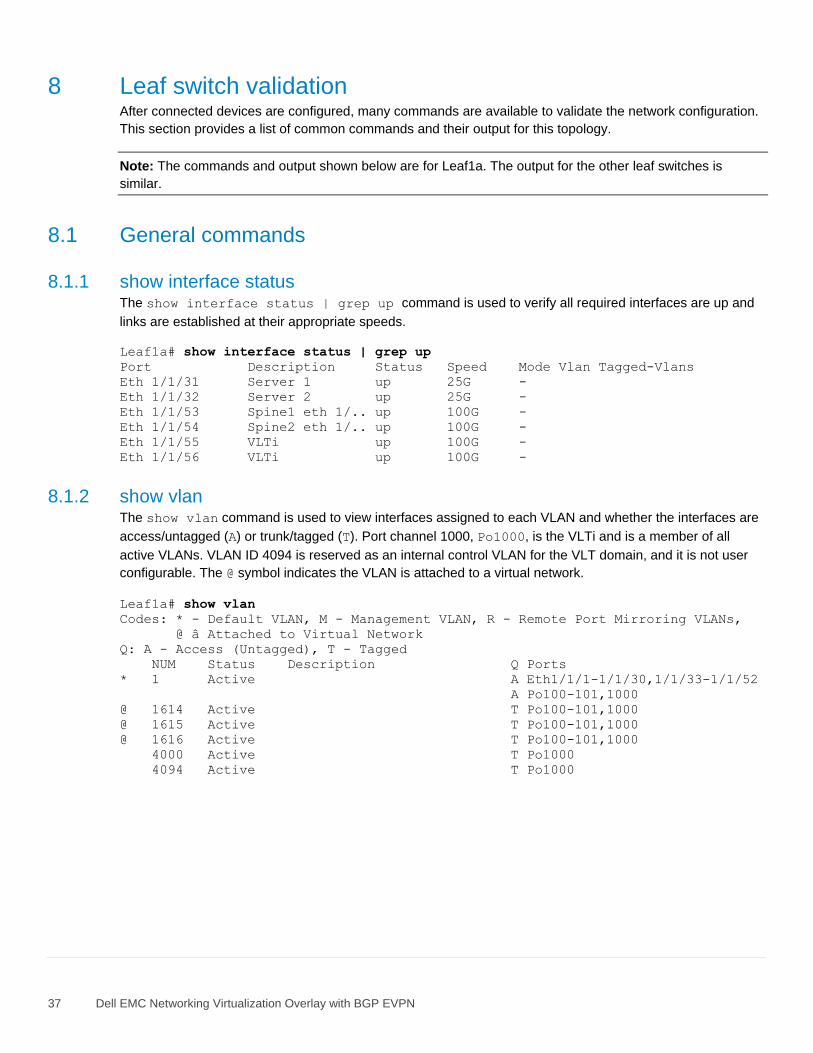
37 Dell EMC Networking Virtualization Overlay with BGP EVPN
8 Leaf switch validation After connected devices are configured, many commands are available to validate the network configuration.
This section provides a list of common commands and their output for this topology.
Note: The commands and output shown below are for Leaf1a. The output for the other leaf switches is
similar.
8.1 General commands
8.1.1 show interface status The show interface status | grep up command is used to verify all required interfaces are up and
links are established at their appropriate speeds.
Leaf1a# show interface status | grep up
Port Description Status Speed Mode Vlan Tagged-Vlans
Eth 1/1/31 Server 1 up 25G -
Eth 1/1/32 Server 2 up 25G -
Eth 1/1/53 Spine1 eth 1/.. up 100G -
Eth 1/1/54 Spine2 eth 1/.. up 100G -
Eth 1/1/55 VLTi up 100G -
Eth 1/1/56 VLTi up 100G -
8.1.2 show vlan The show vlan command is used to view interfaces assigned to each VLAN and whether the interfaces are
access/untagged (A) or trunk/tagged (T). Port channel 1000, Po1000, is the VLTi and is a member of all
active VLANs. VLAN ID 4094 is reserved as an internal control VLAN for the VLT domain, and it is not user
configurable. The @ symbol indicates the VLAN is attached to a virtual network.
Leaf1a# show vlan
Codes: * - Default VLAN, M - Management VLAN, R - Remote Port Mirroring VLANs,
@ â Attached to Virtual Network
Q: A - Access (Untagged), T - Tagged
NUM Status Description Q Ports
* 1 Active A Eth1/1/1-1/1/30,1/1/33-1/1/52
A Po100-101,1000
@ 1614 Active T Po100-101,1000
@ 1615 Active T Po100-101,1000
@ 1616 Active T Po100-101,1000
4000 Active T Po1000
4094 Active T Po1000

38 Dell EMC Networking Virtualization Overlay with BGP EVPN
8.1.3 show lldp neighbors The show lldp neighbors command is useful for identifying connected switches by port. The items listed
as Not Advertised are the server network adapters.
Leaf1a# show lldp neighbors
Loc PortID Rem Host Name Rem Port Id Rem Chassis Id
-----------------------------------------------------------------------------
ethernet1/1/31 Not Advertised f4:e9:d4:62:4b:c8 f4:e9:d4:62:4b:c8
ethernet1/1/32 Not Advertised f4:e9:d4:62:4b:80 f4:e9:d4:62:4b:80
ethernet1/1/53 Spine1 ethernet1/1/1 20:04:0f:05:c0:97
ethernet1/1/54 Spine2 ethernet1/1/1 50:9a:4c:d5:50:70
ethernet1/1/55 Leaf1b ethernet1/1/55 3c:2c:30:10:41:00
ethernet1/1/56 Leaf1b ethernet1/1/56 3c:2c:30:10:41:00
8.1.4 show uplink-state-group id_# detail The show uplink-state-group id_# detail command shows the status of ports in the UFD group.
The status should be Enabled,up. Since UFD is configured in reverse, the VLT port channels connected to
the servers, Po 100 and Po 101, are shown as upstream interfaces and the ports connected to the spines
are shown as downstream interfaces. All interfaces are up.
Leaf1a# show uplink-state-group 1 detail
(Up): Interface up (Dwn): Interface down (Dis): Interface disabled (NA):
Not Available
*: VLT Port-channel V: VLT Status P: Peer Operational Status ^: Tracking
Status
Uplink State Group : 1 Status : Enabled,up
Upstream Interfaces : *Po 100(V:Up,^P:Up) *Po 101(V:Up,^P:Up)
Downstream Interfaces: Eth 1/1/53(Up) Eth 1/1/54(Up)

39 Dell EMC Networking Virtualization Overlay with BGP EVPN
8.2 VLT validation commands
8.2.1 show vlt domain_id VLT configuration is verified by running the show vlt domain_id command on each of the leaf switches.
The Role of one switch in the VLT pair is primary, and its peer switch (not shown) is assigned the
secondary role. The VLTi link status and VLT Peer Status must both be up.
Leaf1a# show vlt 127
Domain ID : 127
Unit ID : 2
Role : primary
Version : 2.3
Local System MAC address : 3c:2c:30:10:36:00
Role priority : 32768
VLT MAC address : 00:00:01:02:03:01
IP address : fda5:74c8:b79e:1::2
Delay-Restore timer : 120 seconds
Peer-Routing : Disabled
Peer-Routing-Timeout timer : 0 seconds
VLTi Link Status
port-channel1000 : up
VLT Peer Unit ID System MAC Address Status IP Address Version
--------------------------------------------------------------------------------
1 3c:2c:30:10:41:00 up fda5:74c8:b79e:1::1 2.3
8.2.2 show vlt domain_id backup-link This command is used to verify VLT peers are communicating on the backup link over the OOB management
network. The Destination is the management IP address of the peer. The Peer HeartBeat status
must be Up.
Leaf1a# show vlt 127 backup-link
VLT Backup Link
------------------------
Destination : 100.67.166.220
Peer Heartbeat status : Up
Heartbeat interval : 30
Heartbeat timeout : 90
Destination VRF : default
8.2.3 show vlt domain_id mismatch This command highlights configuration issues between VLT peers. Mismatch examples include incompatible
VLT configuration settings and VLAN differences. Any mismatches reported should be resolved before
proceeding.
S5248F-Leaf1A# show vlt 127 mismatch
VLT-MAC mismatch:
No mismatch
Peer-routing mismatch:
No mismatch
VLAN mismatch:
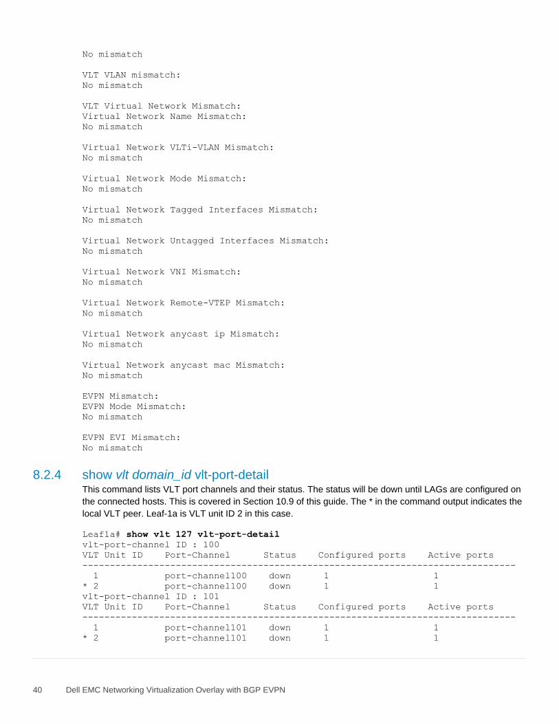
40 Dell EMC Networking Virtualization Overlay with BGP EVPN
No mismatch
VLT VLAN mismatch:
No mismatch
VLT Virtual Network Mismatch:
Virtual Network Name Mismatch:
No mismatch
Virtual Network VLTi-VLAN Mismatch:
No mismatch
Virtual Network Mode Mismatch:
No mismatch
Virtual Network Tagged Interfaces Mismatch:
No mismatch
Virtual Network Untagged Interfaces Mismatch:
No mismatch
Virtual Network VNI Mismatch:
No mismatch
Virtual Network Remote-VTEP Mismatch:
No mismatch
Virtual Network anycast ip Mismatch:
No mismatch
Virtual Network anycast mac Mismatch:
No mismatch
EVPN Mismatch:
EVPN Mode Mismatch:
No mismatch
EVPN EVI Mismatch:
No mismatch
8.2.4 show vlt domain_id vlt-port-detail This command lists VLT port channels and their status. The status will be down until LAGs are configured on
the connected hosts. This is covered in Section 10.9 of this guide. The * in the command output indicates the
local VLT peer. Leaf-1a is VLT unit ID 2 in this case.
Leaf1a# show vlt 127 vlt-port-detail
vlt-port-channel ID : 100
VLT Unit ID Port-Channel Status Configured ports Active ports
-------------------------------------------------------------------------------
1 port-channel100 down 1 1
* 2 port-channel100 down 1 1
vlt-port-channel ID : 101
VLT Unit ID Port-Channel Status Configured ports Active ports
-------------------------------------------------------------------------------
1 port-channel101 down 1 1
* 2 port-channel101 down 1 1

41 Dell EMC Networking Virtualization Overlay with BGP EVPN
8.3 Routing validation commands
8.3.1 show bfd neighbors The show bfd neighbors command shows BFD session information.
Leaf1a# show bfd neighbors
* - Active session role
--------------------------------------------------------------------------------
LocalAddr RemoteAddr Interface State RxInt TxInt Mult VRF Clients
--------------------------------------------------------------------------------
* 10.2.2.1 10.2.1.1 loopback1 down 1000 1000 3 default bgp
* 10.2.2.1 10.2.1.2 loopback1 down 1000 1000 3 default bgp
* 192.168.1.1 192.168.1.0 eth1/1/53 up 200 200 3 default bgp
* 192.168.2.1 192.168.2.0 eth1/1/54 up 200 200 3 default bgp
* 192.168.3.0 192.168.3.1 vlan4000 up 200 200 3 default bgp
8.3.2 show ip route The show ip route command displays the contents of the IPv4 routing table.
Leaf1a# show ip route
Codes: C - connected
S - static
B - BGP, IN - internal BGP, EX - external BGP
O - OSPF, IA - OSPF inter area, N1 - OSPF NSSA external type 1,
N2 - OSPF NSSA external type 2, E1 - OSPF external type 1,
E2 - OSPF external type 2, * - candidate default,
+ - summary route, > - non-active route
Gateway of last resort is not set
Destination Gateway Dist/Met Change
-------------------------------------------------------------------------------
B EX 10.2.1.1/32 via 192.168.1.0 20/0 04:38:05
B EX 10.2.1.2/32 via 192.168.2.0 20/0 04:38:05
C 10.2.2.1/32 via 10.2.2.1 loopback1 0/0 04:38:19
B IN 10.2.2.2/32 via 192.168.3.1 200/0 02:39:34
B EX 10.2.2.3/32 via 192.168.1.0 20/0 02:20:19
via 192.168.2.0
B EX 10.2.2.4/32 via 192.168.1.0 20/0 02:19:55
via 192.168.2.0
B EX 10.2.2.5/32 via 192.168.1.0 20/0 02:18:59
via 192.168.2.0
B EX 10.2.2.6/32 via 192.168.1.0 20/0 02:18:44
via 192.168.2.0
C 10.222.222.1/32 via 10.222.222.1 loopback0 0/0 04:38:20
B EX 10.222.222.2/32 via 192.168.1.0 20/0 02:20:19
via 192.168.2.0
B EX 10.222.222.3/32 via 192.168.1.0 20/0 02:18:59
via 192.168.2.0
C 192.168.1.0/31 via 192.168.1.1 ethernet1/1/53 0/0 04:38:08
C 192.168.2.0/31 via 192.168.2.1 ethernet1/1/54 0/0 04:38:08
C 192.168.3.0/31 via 192.168.3.0 vlan4000 0/0 02:39:37

42 Dell EMC Networking Virtualization Overlay with BGP EVPN
8.3.3 show ip bgp summary The show ip bgp summary command shows summary BGP information regarding neighbor status and
exchanged prefixes.
Leaf1a# show ip bgp summary
BGP router identifier 10.2.2.1 local AS number 65201
Global BFD is enabled
Neighbor AS MsgRcvd MsgSent Up/Down State/Pfx
192.168.1.0 65101 351 338 04:51:28 7
192.168.2.0 65101 346 340 04:51:27 7
192.168.3.1 65201 789 1271 02:52:57 9
8.4 EVPN validation commands
8.4.1 show ip route vrf vrf_name The show ip route vrf vrf_name command shows the virtual network routes.
Leaf1a# show ip route vrf tenant1
Codes: C - connected
S - static
B - BGP, IN - internal BGP, EX - external BGP
O - OSPF, IA - OSPF inter area, N1 - OSPF NSSA external type 1,
N2 - OSPF NSSA external type 2, E1 - OSPF external type 1,
E2 - OSPF external type 2, * - candidate default,
+ - summary route, > - non-active route
Gateway of last resort is via 172.16.16.253 to network 0.0.0.0
Destination Gateway Dist/Met Change
--------------------------------------------------------------------------------
*S 0.0.0.0/0 via 172.16.16.253 virtual-network1616 1/0 00:31:13
C 172.16.14.0/24 via 172.16.14.241 virtual-network1614 0/0 00:30:59
C 172.16.15.0/24 via 172.16.15.241 virtual-network1615 0/0 00:30:59
C 172.16.16.0/24 via 172.16.16.241 virtual-network1616 0/0 00:30:59
8.4.2 show evpn evi The show evpn evi command verifies EVPN instance status, associated VXLAN virtual networks and the
RD and RT values used in BGP EVPN routes in the EVI. The status of integrated routing and bridging (IRB)
and the VRF used for EVPN traffic are also displayed.
Leaf1a# show evpn evi
EVI : 1614, State : up
Bridge-Domain : Virtual-Network 1614, VNI 1614
Route-Distinguisher : 1:10.222.222.1:1614
Route-Targets : 0:1614:1614 both
Inclusive Multicast : 10.222.222.2, 10.222.222.3
IRB : Enabled(tenant1)
EVI : 1615, State : up
Bridge-Domain : Virtual-Network 1615, VNI 1615
Route-Distinguisher : 1:10.222.222.1:1615
Route-Targets : 0:1615:1615 both
Inclusive Multicast : 10.222.222.2, 10.222.222.3
IRB : Enabled(tenant1)

43 Dell EMC Networking Virtualization Overlay with BGP EVPN
EVI : 1616, State : up
Bridge-Domain : Virtual-Network 1616, VNI 1616
Route-Distinguisher : 1:10.222.222.1:1616
Route-Targets : 0:1616:1616 both
Inclusive Multicast : 10.222.222.2, 10.222.222.3
IRB : Enabled(tenant1)
8.4.3 show ip bgp l2vpn evpn summary The show ip bgp l2vpn evpn summary command displays summary information about BGP sessions
using the EVPN address family.
Leaf1a# show ip bgp l2vpn evpn summary
BGP router identifier 10.2.2.1 local AS number 65201
Global BFD is enabled
Neighbor AS MsgRcvd MsgSent Up/Down State/Pfx
10.2.1.1 65101 653 539 04:16:45 56
10.2.1.2 65101 394 508 04:17:08 56
8.4.4 show ip bgp l2vpn evpn The show ip bgp l2vpn evpn command shows EVPN control plane information captured from BGP
updates. Host MAC addresses are shown as routing entries.
Leaf1a# show ip bgp l2vpn evpn
BGP local RIB : Routes to be Added , Replaced , Withdrawn
BGP local router ID is 10.2.2.1
Status codes: s suppressed, S stale, d dampened, h history, * valid, > best
Path source: I - internal, a - aggregate, c - confed-external,
r - redistributed/network, S - stale
Origin codes: i - IGP, e - EGP, ? - incomplete
Network Next Hop
Metric LocPrf Weight Path
*>r Route distinguisher: 10.222.222.1:1614 VNI:1614
[2]:[0]:[48]:[00:50:56:bb:04:4b]:[0]:[0.0.0.0]/280 10.222.222.1
0 100 32768 ?
*>r Route distinguisher: 10.222.222.1:1614 VNI:1614
[2]:[0]:[48]:[00:50:56:bb:0c:ed]:[0]:[0.0.0.0]/280 10.222.222.1
0 100 32768 ?
*>r Route distinguisher: 10.222.222.1:1614 VNI:1614
[2]:[0]:[48]:[00:50:56:bb:f5:03]:[0]:[0.0.0.0]/280 10.222.222.1
0 100 32768 ?
*>r Route distinguisher: 10.222.222.1:1614 VNI:1614
[2]:[0]:[48]:[3c:2c:30:10:41:a3]:[0]:[0.0.0.0]/280 10.222.222.1
0 100 32768 ?
*>r Route distinguisher: 10.222.222.1:1614 VNI:1614
[2]:[0]:[48]:[3c:2c:30:10:41:a4]:[0]:[0.0.0.0]/280 10.222.222.1
0 100 32768 ?
*> Route distinguisher: 10.222.222.1:1614 VNI:1614
[2]:[0]:[48]:[e4:f0:04:81:40:97]:[0]:[0.0.0.0]/280 10.222.222.3
0 100 0 65101 65203 ?
* Route distinguisher: 10.222.222.1:1614 VNI:1614
[2]:[0]:[48]:[e4:f0:04:81:40:97]:[0]:[0.0.0.0]/280 10.222.222.3
0 100 0 65101 65203 ?
*> Route distinguisher: 10.222.222.1:1614 VNI:1614
[2]:[0]:[48]:[e4:f0:04:81:40:98]:[0]:[0.0.0.0]/280 10.222.222.3
0 100 0 65101 65203 ?

44 Dell EMC Networking Virtualization Overlay with BGP EVPN
* Route distinguisher: 10.222.222.1:1614 VNI:1614
[2]:[0]:[48]:[e4:f0:04:81:40:98]:[0]:[0.0.0.0]/280 10.222.222.3
0 100 0 65101 65203 ?
*>r Route distinguisher: 10.222.222.1:1615 VNI:1615
[2]:[0]:[48]:[00:50:56:bb:42:24]:[0]:[0.0.0.0]/280 10.222.222.1
0 100 32768 ?
*>r Route distinguisher: 10.222.222.1:1615 VNI:1615
[2]:[0]:[48]:[00:50:56:bb:d0:77]:[0]:[0.0.0.0]/280 10.222.222.1
0 100 32768 ?
*>r Route distinguisher: 10.222.222.1:1615 VNI:1615
[2]:[0]:[48]:[3c:2c:30:10:41:a3]:[0]:[0.0.0.0]/280 10.222.222.1
0 100 32768 ?
*>r Route distinguisher: 10.222.222.1:1615 VNI:1615
[2]:[0]:[48]:[3c:2c:30:10:41:a4]:[0]:[0.0.0.0]/280 10.222.222.1
0 100 32768 ?
*> Route distinguisher: 10.222.222.1:1615 VNI:1615
[2]:[0]:[48]:[e4:f0:04:81:40:97]:[0]:[0.0.0.0]/280 10.222.222.3
0 100 0 65101 65203 ?
* Route distinguisher: 10.222.222.1:1615 VNI:1615
[2]:[0]:[48]:[e4:f0:04:81:40:97]:[0]:[0.0.0.0]/280 10.222.222.3
0 100 0 65101 65203 ?
*> Route distinguisher: 10.222.222.1:1615 VNI:1615
[2]:[0]:[48]:[e4:f0:04:81:40:98]:[0]:[0.0.0.0]/280 10.222.222.3
0 100 0 65101 65203 ?
* Route distinguisher: 10.222.222.1:1615 VNI:1615
[2]:[0]:[48]:[e4:f0:04:81:40:98]:[0]:[0.0.0.0]/280 10.222.222.3
0 100 0 65101 65203 ?
*>r Route distinguisher: 10.222.222.1:1616 VNI:1616
[2]:[0]:[48]:[00:01:01:01:01:01]:[0]:[0.0.0.0]/280 10.222.222.1
0 100 32768 ?
*>r Route distinguisher: 10.222.222.1:1616 VNI:1616
(output truncated)
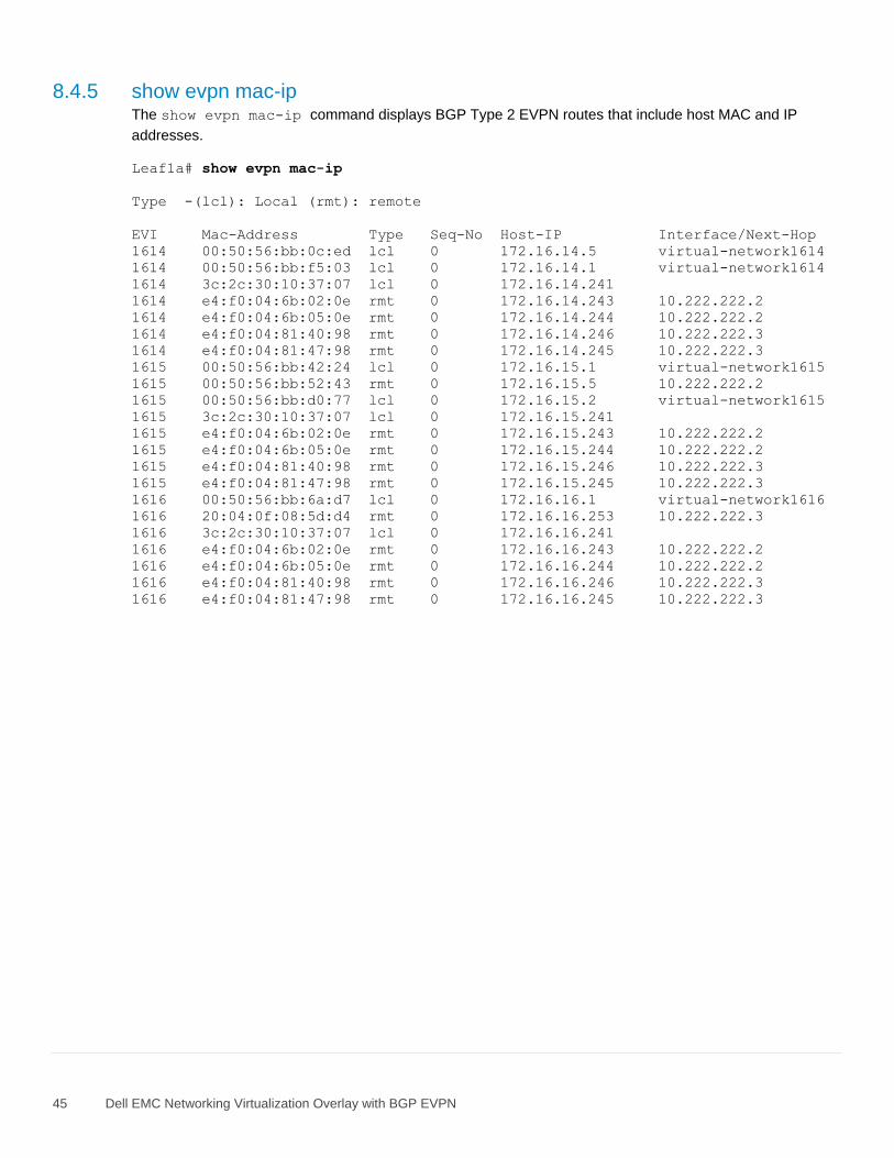
45 Dell EMC Networking Virtualization Overlay with BGP EVPN
8.4.5 show evpn mac-ip The show evpn mac-ip command displays BGP Type 2 EVPN routes that include host MAC and IP
addresses.
Leaf1a# show evpn mac-ip
Type -(lcl): Local (rmt): remote
EVI Mac-Address Type Seq-No Host-IP Interface/Next-Hop
1614 00:50:56:bb:0c:ed lcl 0 172.16.14.5 virtual-network1614
1614 00:50:56:bb:f5:03 lcl 0 172.16.14.1 virtual-network1614
1614 3c:2c:30:10:37:07 lcl 0 172.16.14.241
1614 e4:f0:04:6b:02:0e rmt 0 172.16.14.243 10.222.222.2
1614 e4:f0:04:6b:05:0e rmt 0 172.16.14.244 10.222.222.2
1614 e4:f0:04:81:40:98 rmt 0 172.16.14.246 10.222.222.3
1614 e4:f0:04:81:47:98 rmt 0 172.16.14.245 10.222.222.3
1615 00:50:56:bb:42:24 lcl 0 172.16.15.1 virtual-network1615
1615 00:50:56:bb:52:43 rmt 0 172.16.15.5 10.222.222.2
1615 00:50:56:bb:d0:77 lcl 0 172.16.15.2 virtual-network1615
1615 3c:2c:30:10:37:07 lcl 0 172.16.15.241
1615 e4:f0:04:6b:02:0e rmt 0 172.16.15.243 10.222.222.2
1615 e4:f0:04:6b:05:0e rmt 0 172.16.15.244 10.222.222.2
1615 e4:f0:04:81:40:98 rmt 0 172.16.15.246 10.222.222.3
1615 e4:f0:04:81:47:98 rmt 0 172.16.15.245 10.222.222.3
1616 00:50:56:bb:6a:d7 lcl 0 172.16.16.1 virtual-network1616
1616 20:04:0f:08:5d:d4 rmt 0 172.16.16.253 10.222.222.3
1616 3c:2c:30:10:37:07 lcl 0 172.16.16.241
1616 e4:f0:04:6b:02:0e rmt 0 172.16.16.243 10.222.222.2
1616 e4:f0:04:6b:05:0e rmt 0 172.16.16.244 10.222.222.2
1616 e4:f0:04:81:40:98 rmt 0 172.16.16.246 10.222.222.3
1616 e4:f0:04:81:47:98 rmt 0 172.16.16.245 10.222.222.3
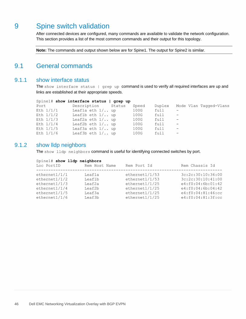
46 Dell EMC Networking Virtualization Overlay with BGP EVPN
9 Spine switch validation After connected devices are configured, many commands are available to validate the network configuration.
This section provides a list of the most common commands and their output for this topology.
Note: The commands and output shown below are for Spine1. The output for Spine2 is similar.
9.1 General commands
9.1.1 show interface status The show interface status | grep up command is used to verify all required interfaces are up and
links are established at their appropriate speeds.
Spine1# show interface status | grep up
Port Description Status Speed Duplex Mode Vlan Tagged-Vlans
Eth 1/1/1 Leaf1a eth 1/.. up 100G full -
Eth 1/1/2 Leaf1b eth 1/.. up 100G full -
Eth 1/1/3 Leaf2a eth 1/.. up 100G full -
Eth 1/1/4 Leaf2b eth 1/.. up 100G full -
Eth 1/1/5 Leaf3a eth 1/.. up 100G full -
Eth 1/1/6 Leaf3b eth 1/.. up 100G full -
9.1.2 show lldp neighbors The show lldp neighbors command is useful for identifying connected switches by port.
Spine1# show lldp neighbors
Loc PortID Rem Host Name Rem Port Id Rem Chassis Id
-----------------------------------------------------------------------------
ethernet1/1/1 Leaf1a ethernet1/1/53 3c:2c:30:10:36:00
ethernet1/1/2 Leaf1b ethernet1/1/53 3c:2c:30:10:41:00
ethernet1/1/3 Leaf2a ethernet1/1/25 e4:f0:04:6b:01:42
ethernet1/1/4 Leaf2b ethernet1/1/25 e4:f0:04:6b:04:42
ethernet1/1/5 Leaf3a ethernet1/1/25 e4:f0:04:81:46:cc
ethernet1/1/6 Leaf3b ethernet1/1/25 e4:f0:04:81:3f:cc

47 Dell EMC Networking Virtualization Overlay with BGP EVPN
9.2 Routing validation commands
9.2.1 show bfd neighbors The show bfd neighbors command shows BFD session information.
Spine1# show bfd neighbors
* - Active session role
--------------------------------------------------------------------------------
LocalAddr RemoteAddr Interface State RxInt TxInt Mult VRF Clients
--------------------------------------------------------------------------------
* 10.2.1.1 10.2.2.1 loopback1 down 1000 1000 3 default bgp
* 10.2.1.1 10.2.2.2 loopback1 down 1000 1000 3 default bgp
* 10.2.1.1 10.2.2.3 loopback1 down 1000 1000 3 default bgp
* 10.2.1.1 10.2.2.4 loopback1 down 1000 1000 3 default bgp
* 10.2.1.1 10.2.2.5 loopback1 down 1000 1000 3 default bgp
* 10.2.1.1 10.2.2.6 loopback1 down 1000 1000 3 default bgp
* 192.168.1.0 192.168.1.1 ethernet1/1/1 up 200 200 3 default bgp
* 192.168.1.2 192.168.1.3 ethernet1/1/2 up 200 200 3 default bgp
* 192.168.1.4 192.168.1.5 ethernet1/1/3 up 200 200 3 default bgp
* 192.168.1.6 192.168.1.7 ethernet1/1/4 up 200 200 3 default bgp
* 192.168.1.8 192.168.1.9 ethernet1/1/5 up 200 200 3 default bgp
* 192.168.1.10 192.168.1.11 ethernet1/1/6 up 200 200 3 default bgp
9.2.2 show ip route The show ip route displays the contents of the IPv4 routing table.
Spine1# show ip route
Codes: C - connected
S - static
B - BGP, IN - internal BGP, EX - external BGP
O - OSPF, IA - OSPF inter area, N1 - OSPF NSSA external type 1,
N2 - OSPF NSSA external type 2, E1 - OSPF external type 1,
E2 - OSPF external type 2, * - candidate default,
+ - summary route, > - non-active route
Gateway of last resort is not set
Destination Gateway Dist/Met Change
--------------------------------------------------------------------------------
C 10.2.1.1/32 via 10.2.1.1 loopback1 0/0 00:53:36
B EX 10.2.2.1/32 via 192.168.1.1 20/0 00:53:12
via 192.168.1.3
B EX 10.2.2.2/32 via 192.168.1.1 20/0 00:53:12
via 192.168.1.3
B EX 10.2.2.3/32 via 192.168.1.5 20/0 00:52:13
via 192.168.1.7
B EX 10.2.2.4/32 via 192.168.1.5 20/0 00:52:13
via 192.168.1.7
B EX 10.2.2.5/32 via 192.168.1.9 20/0 00:52:15
via 192.168.1.11
B EX 10.2.2.6/32 via 192.168.1.9 20/0 00:52:15
via 192.168.1.11
B EX 10.222.222.1/32 via 192.168.1.1 20/0 00:53:12
via 192.168.1.3
B EX 10.222.222.2/32 via 192.168.1.5 20/0 00:52:16
via 192.168.1.7
B EX 10.222.222.3/32 via 192.168.1.9 20/0 00:52:17
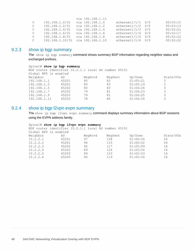
48 Dell EMC Networking Virtualization Overlay with BGP EVPN
via 192.168.1.11
C 192.168.1.0/31 via 192.168.1.0 ethernet1/1/1 0/0 00:53:15
C 192.168.1.2/31 via 192.168.1.2 ethernet1/1/2 0/0 00:53:13
C 192.168.1.4/31 via 192.168.1.4 ethernet1/1/3 0/0 00:52:21
C 192.168.1.6/31 via 192.168.1.6 ethernet1/1/4 0/0 00:52:17
C 192.168.1.8/31 via 192.168.1.8 ethernet1/1/5 0/0 00:52:22
C 192.168.1.10/31 via 192.168.1.10 ethernet1/1/6 0/0 00:52:22
9.2.3 show ip bgp summary The show ip bgp summary command shows summary BGP information regarding neighbor status and
exchanged prefixes.
Spine1# show ip bgp summary
BGP router identifier 10.2.1.1 local AS number 65101
Global BFD is enabled
Neighbor AS MsgRcvd MsgSent Up/Down State/Pfx
192.168.1.1 65201 80 82 01:05:21 3
192.168.1.3 65201 80 83 01:05:19 3
192.168.1.5 65202 80 83 01:04:26 3
192.168.1.7 65202 79 81 01:04:23 3
192.168.1.9 65203 79 81 01:04:25 3
192.168.1.11 65203 78 80 01:04:24 3
9.2.4 show ip bgp l2vpn evpn summary The show ip bgp l2vpn evpn summary command displays summary information about BGP sessions
using the EVPN address family.
Spine1# show ip bgp l2vpn evpn summary
BGP router identifier 10.2.1.1 local AS number 65101
Global BFD is enabled
Neighbor AS MsgRcvd MsgSent Up/Down State/Pfx
10.2.2.1 65201 97 128 01:06:54 24
10.2.2.2 65201 94 133 01:06:52 24
10.2.2.3 65202 92 117 01:05:59 16
10.2.2.4 65202 89 124 01:05:54 16
10.2.2.5 65203 89 123 01:05:53 16
10.2.2.6 65203 90 119 01:05:54 16

49 Dell EMC Networking Virtualization Overlay with BGP EVPN
10 VMware host and network configuration This example uses VMware ESXi VMs running on the four PowerEdge servers to validate the configuration.
VMs are running a mix of Windows Server and Ubuntu Linux guest operating systems. This section shows
how VMs are connected to the virtual networks configured in the preceding sections if ESXi and vCenter are
used in the environment.
10.1 VMware ESXi download and installation Install VMware ESXi 6.7 Update 1 or later on each PowerEdge server. Dell EMC recommends using the
latest Dell EMC customized ESXi .iso image available on support.dell.com. The correct drivers for the
PowerEdge server hardware are built into this image. This image is used to install ESXi by mounting the .iso
image through the PowerEdge server’s iDRAC interface or by using a USB flash drive or CD/DVD.
10.2 Install and configure VMware vCenter Server 6.7 U1
Note: In this deployment, each server has one 1GbE BASE-T interface connected to the OOB management
network for management and communication with the vCenter Server as shown in Figure 13.
For information on the installation and configuration of vCenter Server, refer to vCenter Server 6.7 Installation
and Setup. In this deployment, the vCenter Server communicates with ESXi hosts via the OOB management
network, and it may be located on any host accessible over this network.
10.3 Add ESXi hosts to vCenter Server The vSphere Web Client is a service running on vCenter Server. In the vSphere Web Client, a data center
object named Datacenter is created for this deployment.
In this example, a cluster named Management is created and added to the Datacenter object. The four
R740xd hosts are added to the cluster. When complete, the vSphere Web Client Hosts and Clusters tab in
the Navigator pane appears as shown in Figure 14.
Datacenter and cluster created with ESXi hosts
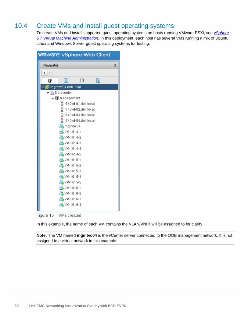
50 Dell EMC Networking Virtualization Overlay with BGP EVPN
10.4 Create VMs and install guest operating systems To create VMs and install supported guest operating systems on hosts running VMware ESXi, see vSphere
6.7 Virtual Machine Administration. In this deployment, each host has several VMs running a mix of Ubuntu
Linux and Windows Server guest operating systems for testing.
VMs created
In this example, the name of each VM contains the VLAN/VNI it will be assigned to for clarity.
Note: The VM named mgmtvc04 is the vCenter server connected to the OOB management network. It is not
assigned to a virtual network in this example.

51 Dell EMC Networking Virtualization Overlay with BGP EVPN
10.5 vSphere distributed switches A vSphere Distributed Switch, also referred to as a VDS or a distributed switch, is a virtual switch that
provides network connectivity to hosts and virtual machines. Unlike vSphere standard switches, distributed
switches act as a single switch across multiple hosts in a cluster.
Distributed switches are configured in the vSphere Web Client, and the configuration is populated across all
hosts associated with the switch. A VDS is used for connectivity to the production network in this guide.
Distributed Switches contain two different port groups:
• Uplink port group – an uplink port group maps physical NICs on the hosts (vmnics) to uplinks on the
VDS. Uplink port groups act as trunks and carry all VLANs by default.
• Distributed port group - Distributed port groups define how connections are made through the VDS
to the network. In this guide, one distributed port group is created for the production network.
Note: For consistent network configuration, connect the same vmnic on every host to the same uplink port on
the distributed switch.
10.6 Create a VDS In this section, a VDS named Mgmt-VDS is created for host access to the production network.
1. In the vSphere Web Client, go to Home > Networking.
2. Right click on Datacenter. Select Distributed switch > New Distributed Switch.
3. Provide a name for the VDS, e.g., Mgmt-VDS. Click Next.
4. On the Select version page, select Distributed switch: 6.6.0 and click Next.
5. On the Edit settings page:
a. Since two NIC ports are used, set the Number of uplinks to 2.
b. Leave Network I/O Control set to Enabled.
c. Uncheck the Create a default port group box.
6. Click Next followed by Finish.
Optionally, allow jumbo frames on the VDS as follows:
1. Right click on Mgmt-VDS and select Settings > Edit Settings.
2. Select Advanced and set MTU (Bytes) to 9000.
3. Click OK.

52 Dell EMC Networking Virtualization Overlay with BGP EVPN
10.7 Add distributed port groups In this section, distributed port groups are created on the VDS. One port group is created for each VNI.
To create the port groups:
1. In the vSphere Web Client, go to Home > Networking.
2. Right-click on Mgmt-VDS. Select Distributed Port Group > New Distributed Port Group.
3. On the Select name and location page, provide a name for the distributed port group to be
associated with the first VNI configured on the leaf switches, e.g., VNI-1614-PG. Click Next.
4. On the Configure settings page, next to VLAN type: select VLAN. Next to VLAN ID, specify the
VLAN associated with the first VNI on the leaf switches. In this example, VLAN 1614 is used.
5. Leave the remaining values at their defaults and click Next > Finish.
6. Complete steps 2 through 4 for the remaining VNIs, 1615 and 1616.
When complete, the Navigator pane appears as shown:
Distributed port groups created
10.8 Create LACP LAGs Since VLT port channels are configured on the leaf switches, LACP LAGs are configured on the VDS.
To enable LACP on Mgmt-VDS:
1. In the vSphere Web Client, go to Home > Networking.
2. In the Navigator pane, select Mgmt-VDS.
3. In the center pane, select Configure > Settings > LACP.
4. Click the icon. The New Link Aggregation Group dialog box opens.
a. Keep the default name, lag1.
b. Set Number of ports equal to the number of physical uplinks on each ESXi host. In this
deployment example, this number is set to 2.
c. Set the Mode to Active. The remaining fields remain at their default values as shown in Figure
17.

53 Dell EMC Networking Virtualization Overlay with BGP EVPN
LAG configuration
d. Click OK to close the dialog box.
This creates lag1 on the VDS. The refresh icon ( ) at the top of the screen may need to be clicked for the
lag to appear in the table as shown in Figure 18.
Lag1 created on Mgmt-VDS

54 Dell EMC Networking Virtualization Overlay with BGP EVPN
10.9 Associate hosts and assign uplinks to LAGs
Note: Before starting this section, be sure you know the vmnic-to-physical adapter mapping for each host
adapter port connected to the leaf switches. This can be determined by going to Home > Hosts and Clusters
and selecting the host in the Navigator pane. In the center pane, select Configure > Networking > Physical
adapters. Vmnic numbering will vary depending on adapters installed in the host.
To add hosts and LAGs to the VDS:
1. In the vSphere Web Client, go to Home > Networking.
2. Right click on Mgmt-VDS and select Add and Manage Hosts.
3. In the Add and Manage Hosts dialog box:
a. On the Select task page, make sure Add hosts is selected. Click Next.
b. On the Select hosts page, Click the New hosts icon. Select the check box next to each host
and click OK > Next.
c. On the Select network adapters tasks page, be sure the Manage physical adapters box is
checked. Be sure all other boxes are unchecked. Click Next.
d. On the Manage physical network adapters page, each host is listed with its vmnics beneath it.
i. Select the first vmnic on the first host and click .
ii. Select lag1-0 > OK.
iii. Select the second vmnic on the first host and click .
iv. Select lag1-1 > OK.
e. Repeat steps i – iv for the remaining hosts. Click Next when done.
f. On the Analyze impact page, Overall impact status should indicate .
g. Click Next > Finish.

55 Dell EMC Networking Virtualization Overlay with BGP EVPN
When complete, the Configure > Settings > Topology page for Mgmt-VDS appears as shown in Figure 19.
LAGs configured on Mgmt-VDS
This configuration brings up the VLT port channels on the leaf switches.
This is confirmed by running the show vlt domain_id vlt-port-detail command on the leafs. The
example below is from Leaf1a. The status for port channels connected to configured hosts is now up as
shown in bold below.
Leaf1a# show vlt 127 vlt-port-detail
vlt-port-channel ID : 100
VLT Unit ID Port-Channel Status Configured ports Active ports
-------------------------------------------------------------------------------
1 port-channel100 up 1 1
* 2 port-channel100 up 1 1
vlt-port-channel ID : 101
VLT Unit ID Port-Channel Status Configured ports Active ports
-------------------------------------------------------------------------------
1 port-channel101 up 1 1
* 2 port-channel101 up 1 1

56 Dell EMC Networking Virtualization Overlay with BGP EVPN
10.10 Connect VMs to VDS and port group In this example, VM network adapters are associated with the VDS and applicable port group.
1. Go to Home > Hosts and Clusters.
2. Right click on a VM, VM-1614-1 in this example, and select Edit Settings.
3. Next to Network adapter 1, select on the drop-down arrow and select Show more networks.
4. Select the applicable port group and VDS from the list. In this case, VNI-1614-PG on Mgmt-VDS is
selected as shown:
Port group and VDS selected
5. Click OK to make the selection.
6. In the Edit Settings window, Network adapter 1 appears as shown:
Virtual wire on App-Tier network selected
7. Click OK to apply the setting.
The network adapter on the VM is now connected to VLAN/VNI 1614. Repeat steps 2-7 for remaining VMs,
placing them on the appropriate VLAN/VNI.

57 Dell EMC Networking Virtualization Overlay with BGP EVPN
10.11 Configure networking in the guest OS For each VM attached to a virtual network, IP addresses and gateways are configured in the guest operating
system per Table 16.
Note: The VLAN/VNI column is shown for reference and does not need to be configured in the guest OS. The
VLAN ID is configured in the distributed port group assigned to the virtual network adapter. VLANs are
associated with corresponding VNIs on the leaf switches.
Virtual machine locations and IP addressing
Virtual machine name VLAN/VNI IP Address Gateway
VM-1614-x 1614 172.16.14.x/24 172.16.14.253
VM-1615-x 1615 172.16.15.x/24 172.16.15.253
VM-1616-x 1616 172.16.16.x/24 172.16.16.253

58 Dell EMC Networking Virtualization Overlay with BGP EVPN
11 Validate connectivity The switches in this guide were configured to allow all VMs to communicate with each other and the external
network. In this section, connectivity is tested between VMs on the same and different VNIs.
Tunneled Layer 2 bridging, routing via anycast gateways, and routing via the indirect gateway are
demonstrated.
Note: Guest operating system firewalls may need to be temporarily disabled or modified to allow responses to
ICMP ping requests.
Rack n
R740xd-1
R740xd-2
R740xd-3
R740xd-4
ECMP
Gateway/
Firewall
S5248F-1a S5248F-1b S4148U-2a S4148U-2b S4148U-3a S4148U-3b
VNI 1614
172.16.14.253
172.16.15.253
172.16.14.253
172.16.15.253
172.16.16.253
VTEP10.222.222.1
Border leafs
eBGP
eBGP
Rack 1 Rack 2
VNI 1614 VNI 1616
VRF tenant1
VLTi
VLT
Z9264F-1 Z9264F-2
VLTVLT
VM-1614-1 VM-1616-1
Physical L3 connection
Physical L2 connection
Virtual L2 connection
Virtual L2 connection
Virtual L2 connection
VM
VM
VM VM on VNI 1614, IP 172.16.14.x /24
VM on VNI 1615, IP 172.16.15.x /24
VM on VNI 1616, IP 172.16.16.x /24
172.16.15.253
172.16.16.253
Anycast gateway - VNI 1614
Anycast gateway - VNI 1615
Indirect gateway - VNI 1616
172.16.14.253
VNI 1615
VLTi VLTi
VTEP10.222.222.2
VTEP10.222.222.3
VM-1614-3 VM-1615-3
Loopback0 1.1.1.1/32
Topology with VMs and IP addresses used in validation examples
11.1 Validate tunneled Layer 2 bridging This test is between two VMs on the same VNI but connected to different leaf pairs. In this example, VM-
1614-1 pings VM-1614-3.
VM-1614-1 has the IP address 172.16.14.1. As shown in Figure 22, it is on R740xd-1 connected to the first
leaf pair in Rack 1. VM-1614-3 has the IP address 172.16.14.3. It is on R740xd-3 connected to the second
leaf pair in Rack 2.
A packet capture of the successful exchange with a ping request selected is shown in Figure 23.
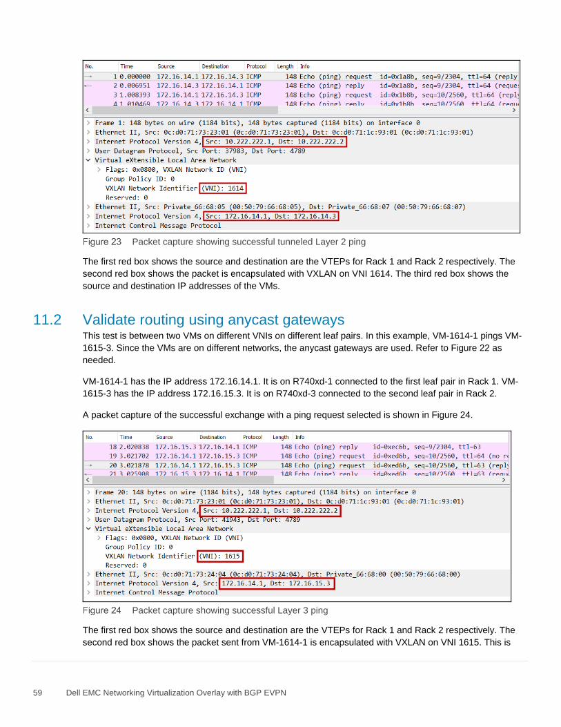
59 Dell EMC Networking Virtualization Overlay with BGP EVPN
Packet capture showing successful tunneled Layer 2 ping
The first red box shows the source and destination are the VTEPs for Rack 1 and Rack 2 respectively. The
second red box shows the packet is encapsulated with VXLAN on VNI 1614. The third red box shows the
source and destination IP addresses of the VMs.
11.2 Validate routing using anycast gateways This test is between two VMs on different VNIs on different leaf pairs. In this example, VM-1614-1 pings VM-
1615-3. Since the VMs are on different networks, the anycast gateways are used. Refer to Figure 22 as
needed.
VM-1614-1 has the IP address 172.16.14.1. It is on R740xd-1 connected to the first leaf pair in Rack 1. VM-
1615-3 has the IP address 172.16.15.3. It is on R740xd-3 connected to the second leaf pair in Rack 2.
A packet capture of the successful exchange with a ping request selected is shown in Figure 24.
Packet capture showing successful Layer 3 ping
The first red box shows the source and destination are the VTEPs for Rack 1 and Rack 2 respectively. The
second red box shows the packet sent from VM-1614-1 is encapsulated with VXLAN on VNI 1615. This is

60 Dell EMC Networking Virtualization Overlay with BGP EVPN
because routing occurs on ingress with asymmetric IRB. This means that packets travel to their destination on
the destination VNI, which is 1615 in this case.
The third red box shows the source and destination IP addresses of the VMs.
11.3 Validate routing using the indirect gateway Two tests are run in this section.
In the first test, a VM that has its default gateway set to the indirect gateway pings the loopback interface on
the Gateway/Firewall switch, 1.1.1.1, to verify connectivity to external networks.
VM-1616-1 has IP address 172.16.16.1. It is on R740xd-1 connected to the first leaf pair in Rack 1. Its default
gateway is the indirect gateway, 172.16.16.253. The Gateway/Firewall switch is connected to the third leaf
pair in Rack 3 as shown in Figure 22.
A packet capture of the successful exchange with a ping request selected is shown in Figure 25.
Packet capture showing successful ping to 1.1.1.1
The first red box shows the source and destination are the VTEPs for Rack 1 and Rack 3 respectively. The
second red box shows the packet is encapsulated with VXLAN on VNI 1616. The third red box shows the
source and destination IP addresses.
In the second test, the same VM, VM-1616-1, pings VM-1615-3 to demonstrate the path taken from a VM that
uses the indirect gateway to a VM that uses an anycast gateway. VM-1615-3 has IP address 172.16.15.3. It is
on R740xd-3 connected to the leaf pair in Rack 2 as shown in Figure 22. Its default gateway is an anycast
gateway, 172.16.15.253.
A packet capture of the successful exchange with a ping request selected is shown in Figure 26.

61 Dell EMC Networking Virtualization Overlay with BGP EVPN
Packet capture showing successful ping between a VM-1615-3 and VM-1616-1
The above capture was taken from a leaf-spine link in Rack 2. The first red box shows the source VTEP is
from Rack 3 and the destination VTEP is in Rack 2. The second red box shows the packet is encapsulated
with VXLAN on VNI 1615. This is because and packets travel to their destination on the destination VNI with
asymmetric IRB. The third red box shows the source and destination IP addresses.

62 Dell EMC Networking Virtualization Overlay with BGP EVPN
A Gateway/firewall switch configuration
This section details the configuration of an S4112F-ON switch used as the external gateway/simulated firewall
to validate this deployment example. This switch is connected to the border leafs, Leaf3a and Leaf3b, as
shown in Figure 12.
A.1 Initial configuration settings
1. Enter configuration mode with the configure terminal command.
2. Configure the hostname.
3. If DHCP is not used, configure the OOB management IP address and default gateway.
4. Enable spanning tree protocol as a precaution against loops. Any spanning tree protocol type
supported by the switch is acceptable. This example uses RSTP.
Initial configuration settings
Gateway/firewall switch
configure terminal
hostname Gateway-FW
interface mgmt 1/1/1
no ip address
ip address 100.67.166.235/24
no shutdown
management route 0.0.0.0/0
100.67.166.254
spanning-tree mode rstp
A.2 Indirect gateway configuration
1. Configure VLAN 1.
2. Specify the IP address used as the indirect gateway.
Gateway configuration
Gateway/firewall switch
interface vlan1
no shutdown
ip address 172.16.16.253/24
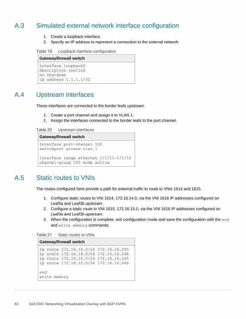
63 Dell EMC Networking Virtualization Overlay with BGP EVPN
A.3 Simulated external network interface configuration
1. Create a loopback interface.
2. Specify an IP address to represent a connection to the external network.
Loopback interface configuration
Gateway/firewall switch
interface loopback0
description testlo0
no shutdown
ip address 1.1.1.1/32
A.4 Upstream interfaces
These interfaces are connected to the border leafs upstream.
1. Create a port channel and assign it to VLAN 1.
2. Assign the interfaces connected to the border leafs to the port channel.
Upstream interfaces
Gateway/firewall switch
interface port-channel 100
switchport access vlan 1
interface range ethernet 1/1/11-1/1/12
channel-group 100 mode active
A.5 Static routes to VNIs
The routes configured here provide a path for external traffic to route to VNIs 1614 and 1615.
1. Configure static routes to VNI 1614, 172.16.14.0, via the VNI 1616 IP addresses configured on
Leaf3a and Leaf3b upstream.
2. Configure a static route to VNI 1615, 172.16.15.0, via the VNI 1616 IP addresses configured on
Leaf3a and Leaf3b upstream.
3. When the configuration is complete, exit configuration mode and save the configuration with the end
and write memory commands.
Static routes to VNIs
Gateway/firewall switch
ip route 172.16.14.0/24 172.16.16.245
ip route 172.16.14.0/24 172.16.16.246
ip route 172.16.15.0/24 172.16.16.245
ip route 172.16.15.0/24 172.16.16.246
end
write memory

64 Dell EMC Networking Virtualization Overlay with BGP EVPN
B Validated components
The following tables include the hardware, software, and firmware used to configure and validate the
examples in this guide.
B.1 Dell EMC PowerSwitches
Switches and OS versions
Qty Item OS Version
2 Dell EMC PowerSwitch S5248F-ON leaf switch 10.4.3.1.154
4 Dell EMC PowerSwitch S4148U-ON leaf switch 10.4.3.1.154
2 Dell EMC PowerSwitch Z9264-ON spine switch 10.4.3.1.154
1 Dell EMC PowerSwitch S3048-ON management switch 10.4.3.1.154
Note: Leaf switches used for this deployment must support native VXLAN routing (RIOT). As of this writing,
this includes Dell EMC S41xx-ON and S52xx-ON series, S4048T-ON and S6010-ON switches.
B.2 PowerEdge R740xd Servers
PowerEdge R740xd components
Qty per server
Item Firmware
2 Intel(R) Xeon(R) Gold 6130 CPU @ 2.10GHz (16 cores) -
4 16GB DDR4 DIMM (64GB total) -
10 400GB SAS SSD -
1 Dell HBA330 Storage Controller 16.17.00.03
1 QLogic FastLinQ QL41262HxCU-DE 2x25GbE SFP28 14.07.50
1 Intel X710 2x10GbE SFP+/i350 2x1GbE BASE-T rNDC 18.8.9
- BIOS 1.6.12
- iDRAC with Lifecycle Controller 3.21.26.22
B.3 VMware software
VMware software versions
Item Version
VMware ESXi 6.7.0 Update 1 build 10764712 - Dell EMC customized image version A04
VMware vCenter Server Appliance 6.7 Update 1 – build 10244845 (Includes vSphere Web Client)

65 Dell EMC Networking Virtualization Overlay with BGP EVPN
C Technical resources
C.1 Dell EMC product manuals and technical guides
Dell EMC Networking Guides
OS10 Enterprise Edition User Guide Release 10.4.3.0
Dell EMC Networking OS10 Enterprise Edition Quick Start Guide
Dell EMC Networking Layer 3 Leaf-Spine Deployment and Best Practices with OS10
Manuals and documentation for Dell EMC PowerSwitch S3048-ON
Manuals and documentation for Dell EMC PowerSwitch S4148U-ON
Manuals and documentation for Dell EMC PowerSwitch S5248F-ON
Manuals and documentation for Dell EMC PowerSwitch Z9264F-ON
Manuals and documentation for Dell EMC PowerEdge R740xd
C.1 VMware product manuals and technical guides
VMware vSphere Documentation
VMware ESXi 6.7 Installation and Setup
vCenter Server 6.7 Installation and Setup
vSphere 6.7 Virtual Machine Administration

66 Dell EMC Networking Virtualization Overlay with BGP EVPN
D Fabric Design Center
The Dell EMC Fabric Design Center (FDC) is a cloud-based application that automates the planning, design,
and deployment of network fabrics that power Dell EMC compute, storage and hyper-converged infrastructure
solutions. The FDC is ideal for turnkey solutions and automation based on validated deployment guides.
FDC allows design customization and flexibility to go beyond validated deployment guides. For additional
information, visit the Dell EMC Fabric Design Center.

67 Dell EMC Networking Virtualization Overlay with BGP EVPN
E Support and feedback
Contacting Technical Support
Support Contact Information Web: http://www.dell.com/support
Telephone: USA: 1-800-945-3355
Feedback for this document
We encourage readers to provide feedback on the quality and usefulness of this publication by sending an
email to [email protected].