Dell Chassis Management Controller Version 1.1 for ... · 16/06/2009 · Enabling or Disabling DHCP...
161
Dell Chassis Management Controller Version 1.1 for PowerEdge FX2/FX2s User's Guide
Transcript of Dell Chassis Management Controller Version 1.1 for ... · 16/06/2009 · Enabling or Disabling DHCP...
Dell Chassis Management Controller Version 1.1 for PowerEdge FX2/FX2sUser's Guide

Notes, Cautions, and WarningsNOTE: A NOTE indicates important information that helps you make better use of your computer.
CAUTION: A CAUTION indicates either potential damage to hardware or loss of data and tells you how to avoid the problem.
WARNING: A WARNING indicates a potential for property damage, personal injury, or death.
Copyright © 2014 Dell Inc. All rights reserved. This product is protected by U.S. and international copyright and intellectual property laws. Dell™ and the Dell logo are trademarks of Dell Inc. in the United States and/or other jurisdictions. All other marks and names mentioned herein may be trademarks of their respective companies.
2014 - 12
Rev. A00
Contents
1 Overview............................................................................................................... 11Key Features.........................................................................................................................................12
What Is New In This Release......................................................................................................... 12
Management Features................................................................................................................... 12
Security Features............................................................................................................................13
Chassis Overview.................................................................................................................................13
Supported Remote Access Connections............................................................................................15
Supported Platforms........................................................................................................................... 16
Supported Web Browsers....................................................................................................................16
Managing Licenses ............................................................................................................................. 16
Types of Licenses...........................................................................................................................16
Acquiring Licenses.........................................................................................................................16
License Operations........................................................................................................................16
Licensable Features In CMC.......................................................................................................... 17
License Component State or Condition and Available Operations............................................ 18
Viewing Localized Versions of the CMC Web Interface.................................................................... 19
Supported Management Console Applications................................................................................. 19
How to Use this User's Guide............................................................................................................. 19
Other Documents You May Need...................................................................................................... 19
Accessing documents from Dell support site....................................................................................20
2 Installing and Setting Up CMC......................................................................... 22Installing CMC Hardware.................................................................................................................... 22
Checklist To Set up Chassis.......................................................................................................... 22
Using Remote Access Software From a Management Station....................................................24
Remote RACADM Installation....................................................................................................... 26
Installing Remote RACADM on a Windows Management Station...............................................27
Installing Remote RACADM on a Linux Management Station..................................................... 27
Uninstalling Remote RACADM From a Linux Management Station............................................ 27
Configuring a Web Browser..........................................................................................................28
Downloading and Updating CMC Firmware................................................................................29
Setting Chassis Physical Location and Chassis Name................................................................. 29
Setting Date and Time on CMC....................................................................................................29
Configuring LEDs to Identify Components on the Chassis........................................................ 30
Configuring CMC Properties........................................................................................................ 30
Configuring Front Panel................................................................................................................ 31
Configuring Chassis Management at Server Mode............................................................................31
Configuring Chassis Management at Server Using CMC Web Interface.................................... 31
Configuring Chassis Management at Server Mode Using RACADM...........................................32
3 Logging in to CMC..............................................................................................33Configure Public Key Authentication Over SSH.................................................................................33
Generating Public Keys for Systems Running Windows..............................................................33
Generating Public Keys for Systems Running Linux.................................................................... 34
Accessing CMC Web Interface........................................................................................................... 34
Logging Into CMC as a Local User, Active Directory User, or LDAP User........................................ 35
Logging in to CMC Using a Smart Card............................................................................................. 36
Logging Into CMC Using Single Sign-on........................................................................................... 36
Logging In To CMC Using Serial, Telnet, Or SSH Console................................................................37
Logging in to CMC Using Public Key Authentication........................................................................ 37
Multiple CMC Sessions....................................................................................................................... 38
4 Updating Firmware............................................................................................ 39Signed CMC Firmware Image.............................................................................................................39
Downloading CMC Firmware.............................................................................................................40
Viewing Currently Installed Firmware Versions................................................................................. 40
Viewing Currently Installed Firmware Versions Using CMC Web Interface............................... 40
Viewing Currently Installed Firmware Versions Using RACADM.................................................40
Updating the CMC Firmware..............................................................................................................40
Updating CMC Firmware Using Web Interface............................................................................ 41
Updating CMC Firmware Using RACADM.................................................................................... 41
Updating the CMC Using DUP........................................................................................................... 42
Updating Chassis Infrastructure Firmware.........................................................................................42
Updating Chassis Infrastructure Firmware Using CMC Web Interface.......................................42
Updating Chassis Infrastructure Firmware Using RACADM........................................................ 43
Updating Server iDRAC Firmware.......................................................................................................43
Updating Server iDRAC Firmware Using Web Interface.............................................................. 43
Updating Server Component Firmware....................................................................................... 43
Enabling Lifecycle Controller....................................................................................................... 46
Choosing Server Component Firmware Update Type Using CMC Web Interface.................... 47
Filtering Components for Firmware Updates...............................................................................47
Viewing Firmware Inventory......................................................................................................... 47
Saving Chassis Inventory Report Using CMC Web Interface...................................................... 49
Configuring Network Share Using CMC Web Interface..............................................................49
Lifecycle Controller Job Operations............................................................................................ 50
5 Viewing Chassis Information and Monitoring Chassis and Component Health................................................................................................56
Viewing Chassis and Component Summaries...................................................................................56
Chassis Graphics........................................................................................................................... 56
Selected Component Information................................................................................................57
Viewing Server Model Name and Service Tag............................................................................. 58
Viewing Chassis Summary..................................................................................................................58
Viewing Chassis Controller Information and Status..........................................................................58
Viewing Information and Health Status of All Servers....................................................................... 58
Viewing Information and Health Status of the IOMs.........................................................................59
Viewing Information and Health Status of Fans................................................................................ 59
Configuring Fans...........................................................................................................................60
Viewing Front Panel Properties.......................................................................................................... 60
Viewing KVM Information and Health Status.....................................................................................60
Viewing Information and Health Status of Temperature Sensors.....................................................61
6 Configuring CMC................................................................................................62Enabling or Disabling DHCP for the CMC Network Interface Address............................................ 62
Enabling the CMC Network Interface................................................................................................ 63
Enabling or Disabling DHCP for DNS IP Addresses...........................................................................64
Setting Static DNS IP addresses..........................................................................................................64
Viewing and Modifying CMC Network LAN Settings.........................................................................64
Viewing and Modifying CMC Network LAN Settings Using CMC Web Interface.......................65
Viewing and Modifying CMC Network LAN Settings Using RACADM........................................ 65
Configuring DNS Settings (IPv4 and IPv6)..........................................................................................65
Configuring Auto Negotiation, Duplex Mode, and Network Speed (IPv4 and IPv6)........................66
Configuring Management Port 2....................................................................................................... 66
Configuring Management Port 2 Using CMC Web Interface......................................................66
Configuring Management Port 2 Using RACADM............................................................................. 67
Configuring Services........................................................................................................................... 67
Configuring Services Using RACADM.......................................................................................... 68
Configuring CMC Extended Storage Card.........................................................................................68
Setting Up Chassis Group...................................................................................................................69
Adding Members To Chassis Group.............................................................................................69
Removing a Member from the Leader......................................................................................... 70
Disbanding a Chassis Group......................................................................................................... 70
Disabling an Individual Member at the Member Chassis.............................................................70
Launching the Web page of a Member Chassis or Server........................................................... 71
Propagating Leader Chassis Properties to Member Chassis........................................................71
Synchronizing a New Member With Leader Chassis Properties..................................................72
Server Inventory for MCM group.................................................................................................. 72
Saving Server Inventory Report.....................................................................................................72
Configuring Multiple CMCs Using RACADM......................................................................................73
Parsing Rules..................................................................................................................................73
Modifying the CMC IP Address..................................................................................................... 75
7 Configuring Servers............................................................................................76Configuring Slot Names......................................................................................................................76
Configuring iDRAC Network Settings.................................................................................................77
Configuring iDRAC QuickDeploy Network Settings.................................................................... 77
QuickDeploy IP Address Assignments For Servers......................................................................80
Modifying iDRAC Network Settings for Individual Server iDRAC................................................80
Modifying iDRAC Network Settings Using RACADM....................................................................81
Configuring iDRAC VLAN Tag Settings.........................................................................................81
Configuring iDRAC VLAN Tag Settings Using Web Interface...................................................... 81
Configuring iDRAC VLAN Tag Settings Using RACADM..............................................................82
Setting First Boot Device.....................................................................................................................82
Setting First Boot Device For Multiple Servers Using CMC Web Interface................................. 83
Setting First Boot Device For Individual Server Using CMC Web Interface................................ 83
Setting First Boot Device Using RACADM....................................................................................84
Configuring Sled Network Uplink.......................................................................................................84
Deploying Remote File Share............................................................................................................. 84
Configuring Server FlexAddress..........................................................................................................85
Configuring Profile Settings Using Server Configuration Replication.............................................. 85
Accessing Profile Page..................................................................................................................86
Managing Stored Profiles..............................................................................................................86
Adding or Saving Profile................................................................................................................86
Applying Profile..............................................................................................................................87
Importing Profile........................................................................................................................... 88
Exporting Profile............................................................................................................................88
Editing Profile................................................................................................................................ 88
Viewing Profile Settings................................................................................................................ 89
Viewing Stored Profile Settings.................................................................................................... 89
Viewing Profile Log....................................................................................................................... 89
Completion Status And Troubleshooting.................................................................................... 89
Quick Deploy of Profiles...............................................................................................................90
Assigning Server Profiles to Slots ................................................................................................ 90
Launching iDRAC using Single Sign-On.......................................................................................91
Launching Remote Console from Server Status Page...................................................................... 92
8 Configuring CMC To Send Alerts.................................................................... 93Enabling Or Disabling Alerts............................................................................................................... 93
Enabling Or Disabling Alerts Using CMC Web Interface............................................................. 93
Enabling Or Disabling Alerts Using RACADM...............................................................................93
Filtering Alerts................................................................................................................................93
Configuring Alert Destinations........................................................................................................... 94
Configuring SNMP Trap Alert Destinations..................................................................................94
Configuring E-Mail Alert Settings................................................................................................. 95
9 Configuring User Accounts and Privileges....................................................98Types of Users.....................................................................................................................................98
Modifying Root User Administrator Account Settings.....................................................................102
Configuring Local Users................................................................................................................... 102
Configuring Local Users Using CMC Web Interface..................................................................102
Configure Local Users Using RACADM...................................................................................... 102
Configuring Active Directory Users..................................................................................................103
Supported Active Directory Authentication Mechanisms......................................................... 103
Standard Schema Active Directory Overview............................................................................ 104
Configuring Standard Schema Active Directory........................................................................ 105
Extended Schema Active Directory Overview........................................................................... 105
Configuring Extended Schema Active Directory....................................................................... 105
Configuring Generic LDAP Users..................................................................................................... 105
Configuring the Generic LDAP Directory to Access CMC........................................................ 105
Configuring Generic LDAP Directory Service Using CMC Web Interface................................ 105
Configuring Generic LDAP Directory Service Using RACADM..................................................106
10 Configuring CMC For Single Sign-On Or Smart Card Login..................108System Requirements....................................................................................................................... 108
Client Systems............................................................................................................................. 109
CMC.............................................................................................................................................109
Prerequisites For Single Sign-On Or Smart Card Login.................................................................. 109
Generating Kerberos Keytab File...................................................................................................... 109
Configuring CMC For Active Directory Schema.............................................................................. 110
Configuring Browser For SSO Login.................................................................................................110
Internet Explorer.......................................................................................................................... 110
Mozilla FireFox............................................................................................................................. 110
Configuring Browser For Smart Card Login.....................................................................................110
Configuring CMC SSO Login Or Smart Card Login For Active Directory Users Using RACADM... 111
Configuring CMC SSO Or Smart Card Login For Active Directory Users Using Web Interface..... 111
Uploading Keytab File........................................................................................................................ 111
Configuring CMC SSO Login Or Smart Card Login For Active Directory Users Using RACADM...112
11 Configuring CMC to Use Command Line Consoles................................. 113CMC Command Line Console Features...........................................................................................113
CMC Command Line Interface Commands...............................................................................113
Using Telnet Console With CMC...................................................................................................... 114
Using SSH With CMC................................................................................................................... 114
Supported SSH Cryptography Schemes..................................................................................... 114
Configure Public Key Authentication Over SSH......................................................................... 115
Configuring Terminal Emulation Software.......................................................................................116
Connecting to Servers or I/O Module Using Connect Command..................................................116
Configuring the Managed Server BIOS for Serial Console Redirection.....................................117
Configuring Windows for Serial Console Redirection............................................................... 118
Configuring Linux for Server Serial Console Redirection During Boot..................................... 118
Configuring Linux for Server Serial Console Redirection After Boot.........................................119
12 Using FlexAddress and FlexAddress Plus Cards........................................ 121About FlexAddress............................................................................................................................. 121
About FlexAddress Plus................................................................................................................121
Verifying FlexAddress Activation................................................................................................. 122
Deactivating FlexAddress............................................................................................................ 123
Configuring FlexAddress................................................................................................................... 124
Configuring FlexAddress for Chassis-Level Fabric and Slots.....................................................124
Viewing World Wide Name/Media Access Control (WWN/MAC) IDs....................................... 124
Command Messages.........................................................................................................................124
FlexAddress DELL SOFTWARE LICENSE AGREEMENT.................................................................... 126
Viewing WWN/MAC Address Information........................................................................................128
Viewing Basic WWN/MAC Address Information Using Web Interface........................................... 129
Viewing Advanced WWN/MAC Address Information Using Web Interface....................................129
Viewing WWN/MAC Address Information Using RACADM............................................................. 130
13 Managing Fabrics............................................................................................132Monitoring IOM Health..................................................................................................................... 132
Configuring Network Settings for IOM.............................................................................................132
Configuring Network Settings for IOM Using CMC Web Interface...........................................133
Configuring Network Settings for IOM Using RACADM............................................................ 133
Viewing I/O Module Uplink and Downlink Status Using Web Interface......................................... 133
Viewing I/O Module FCoE Session Information Using Web Interface............................................134
Resetting IOM to Factory Default Settings.......................................................................................134
Updating IOM Software Using CMC Web Interface........................................................................ 134
14 Using VLAN Manager..................................................................................... 136Assigning VLAN to IOM..................................................................................................................... 136
Configuring VLAN settings on IOMs Using CMC Web Interface ....................................................136
Viewing the VLAN settings on IOMs Using CMC Web Interface..................................................... 137
Viewing the Current VLAN Settings on IOMs Using CMC Web Interface....................................... 137
Removing VLANs for IOMs Using CMC Web Interface....................................................................137
Updating Untagged VLANs for IOMs Using CMC Web Interface....................................................138
Resetting VLANs for IOMs Using CMC Web Interface.....................................................................138
15 Managing and Monitoring Power................................................................139

Redundancy Policies.........................................................................................................................140
Grid Redundancy Policy..............................................................................................................140
No Redundancy Policy................................................................................................................140
Redundancy Alerting Only Policy...............................................................................................140
PSU Failures................................................................................................................................. 140
Default Redundancy Configuration................................................................................................. 140
Multi-node Sled Adaptation..............................................................................................................140
Chassis Power Limit Monitoring....................................................................................................... 141
Viewing Power Consumption Status................................................................................................ 141
Viewing Power Consumption Status Using CMC Web Interface.............................................. 141
Viewing Power Consumption Status Using RACADM................................................................141
Viewing Power Budget Status Using CMC Web Interface............................................................... 141
Viewing Power Budget Status Using RACADM................................................................................ 141
Redundancy Status and Overall Power Health................................................................................ 142
Power Management After PSU Failure....................................................................................... 142
Power Supply and Redundancy Policy Changes in System Event Log.....................................142
Configuring Power Budget and Redundancy............................................................................ 143
Executing Power Control Operations........................................................................................ 145
Executing Power Control Operations for Multiple Servers Using CMC Web Interface........... 145
Executing Power Control Operations on the IOM.................................................................... 146
16 Viewing PCIe Slots..........................................................................................147Viewing PCIe Slot Properties Using CMC Web Interface................................................................ 147
Viewing PCIe Slot Properties Using RACADM................................................................................. 148
17 Troubleshooting and Recovery................................................................... 149Gathering Configuration Information, Chassis Status, and Logs Using RACDUMP.......................149
Supported Interfaces...................................................................................................................149
Downloading SNMP Management Information Base (MIB) File................................................150
First Steps to Troubleshoot a Remote System...........................................................................150
Troubleshooting Alerts................................................................................................................ 151
Viewing Event Logs......................................................................................................................151
Using Diagnostic Console...........................................................................................................152
Resetting Components............................................................................................................... 152
Saving or Restoring Chassis Configuration................................................................................ 152
Troubleshooting Network Time Protocol (NTP) Errors............................................................. 153
Interpreting LED Colors and Blinking Patterns...........................................................................154
Troubleshooting Network Problems.......................................................................................... 157
General Troubleshooting.................................................................................................................. 157
18 Frequently Asked Questions.........................................................................158RACADM............................................................................................................................................ 158

Managing and Recovering a Remote System.................................................................................. 159
Active Directory.................................................................................................................................160
IOM.....................................................................................................................................................161
Event and Error Messages................................................................................................................. 161
1OverviewThe Dell Chassis Management Controller (CMC) for PowerEdge FX2/FX2s is a Systems Management hardware and software solution for managing the PowerEdge FX2/FX2s chassis. The CMC has its own microprocessor and memory and is powered by the modular chassis into which it is plugged.
The CMC enables an IT administrator to:
• View inventory.
• Perform configuration and monitoring tasks.
• Remotely turn on and turn off chassis and servers.
• Enable alerts for events on servers and components in the server module.
• View the PCIe mapping information.
• Provide a one–many management interface to the iDRACs and I/O modules in the chassis.
The CMC provides multiple System Management functions for servers. Power and thermal management are the primary functions of CMC, which are listed as follows:
• Enclosure-level real-time automatic power and thermal management.
– The CMC reports real-time power consumption, which includes logging high and low points with a time stamp.
– The CMC supports setting an optional enclosure maximum power limit (System Input Power Cap), which alerts and takes actions such as limiting the power consumption of servers, and/or preventing the turning on of new servers to keep the enclosure under the defined maximum power limit.
– The CMC monitors and automatically controls the functions of cooling fans based on actual ambient and internal temperature measurements.
– The CMC provides comprehensive enclosure inventory and status or error reporting.
• The CMC provides a mechanism for centralized configuration of the:
– Network and security setting of the PowerEdge FX2/FX2s enclosure.
– Power redundancy and power ceiling settings.
– I/O switch and iDRAC network settings.
– First boot device on the server module.
– I/O fabric consistency checks between the I/O module and servers. CMC also disables components, if necessary, to protect the system hardware.
– User access security.
– PCIe slots.
You can configure CMC to send email alerts or SNMP trap alerts for warnings or errors such as temperature, hardware misconfiguration, power outage, and fan speed.
11
Key Features
The CMC features are grouped into management and security features.
What Is New In This Release
This release of CMC for Dell PowerEdge FX2/FX2s supports:
• 13th generation Blade Servers.
• Enhanced WWN/MAC Address Inventory that includes WWN/MAC addresses assigned to a LOM/Select Network Adapter (SNA) using the iDRAC IO Identity feature.
• Viewing status of NIC Partitions as part of the WWN/MAC Address Inventory independent of the OS.
• Using directories in the remote NFS/CIFS directory for server profiles and custom repository of DUPs.
• Option to use an external library (CIFS/NFS directory) to update repositories and profiles.
• Option to view and use captured profiles stored on an external library.
• Enhanced WWN/MAC Address Inventory using the iDRAC IO Identity feature.
• Enforcement of signature checking for CMC firmware images.
• Updating CMC using DUP
Management Features
CMC provides the following management features:
• Dynamic Domain Name System (DDNS) registration for IPv4 and IPv6.
• Login management and configuration for local users, Active Directory, and LDAP.
• Remote system management and monitoring using SNMP, a web interface, integrated KVM, Telnet, or SSH connection.
• Monitoring — Provides access to system information and status of components.
• Access to system event logs — Provides access to the hardware log and chassis log.
• Firmware updates for various chassis components — Enables you to update the firmware for CMC, iDRAC on servers, and chassis infrastructure.
• Firmware update of server components such as BIOS, network controllers, and so on across multiple servers in the chassis using Lifecycle Controller.
• Dell OpenManage software integration — Enables you to launch the CMC web interface from Dell OpenManage Server Administrator or OpenManage Essentials (OME) 1.2.
• CMC alert — Alerts you about potential managed node issues through Remote syslog email message or SNMP trap.
• Remote power management — Provides remote power management functions, such as turn off and reset of any chassis component, from a management console.
• Power usage reporting.
• Secure Sockets Layer (SSL) encryption — Provides secure remote system management through the web interface.
• Launch point for the Integrated Dell Remote Access Controller (iDRAC) web interface.
• Support for WS-Management.
• Multi-node Sled adaptation. PowerEdge FM120x4 is a multi-node Sled.
12
• Chassis Power Limit Monitoring.
• iDRAC IO Identity feature support for enhanced WWN/MAC Address Inventory.
• FlexAddress feature — Replaces the factory-assigned World Wide Name/Media Access Control (WWN/MAC) IDs with chassis-assigned WWN/MAC IDs for a particular slot, an optional upgrade.
• Graphical display of chassis component status and health.
• Support for single and multi-slot servers.
• iDRAC single sign-on.
• Network time protocol (NTP) support.
• Enhanced server summary, power reporting, and power control pages.
• Multi-chassis management, allows up to 19 other chassis to be visible from the lead chassis.
NOTE: Multi-Chassis Management is not supported on IPv6 networks.
Security Features
The CMC provides the following security features:
• Password-level security management — Prevents unauthorized access to a remote system.
• Centralized user authentication through:
– Active Directory using Standard Schema or an Extended Schema (optional).
– Hardware-stored user IDs and passwords.
• Role-based authority — Enables an administrator to configure specific privileges for each user.
• User ID and password configuration through the web interface. Web interface supports 128-bit SSL 3.0 encryption and 40-bit SSL 3.0 encryption (for countries where 128-bit is not acceptable).
NOTE: Telnet does not support SSL encryption.
• Configurable IP ports (if applicable).
• Login failure limits per IP address, with login blocking from the IP address when the limit is exceeded.
• Configurable session auto time out, and more than one simultaneous sessions.
• Limited IP address range for clients connecting to CMC.
• Secure Shell (SSH), which uses an encrypted layer for higher security.
• Single Sign-on, Two-Factor Authentication, and Public Key Authentication.
• CMC Signed Image — Used to protect the firmware image from undetected modification using digital signature.
Chassis Overview
A Back Panel view of the chassis is given here with a table that lists the parts and devices available in the CMC.
13
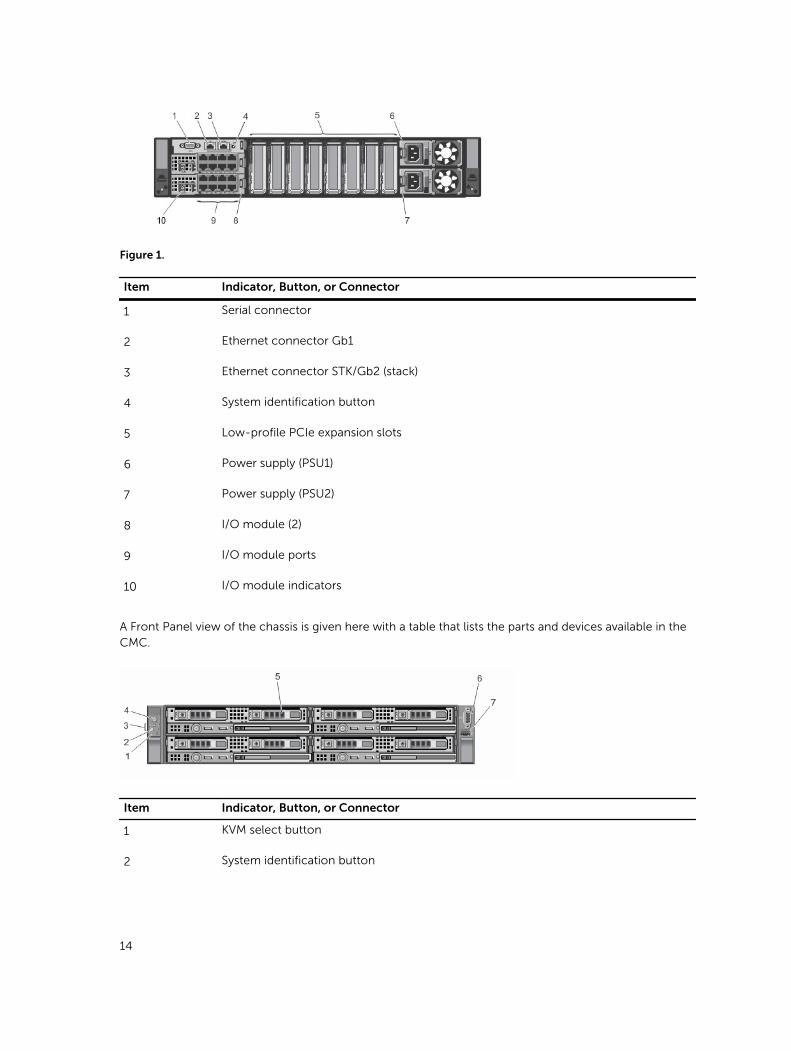
Figure 1.
Item Indicator, Button, or Connector
1 Serial connector
2 Ethernet connector Gb1
3 Ethernet connector STK/Gb2 (stack)
4 System identification button
5 Low-profile PCIe expansion slots
6 Power supply (PSU1)
7 Power supply (PSU2)
8 I/O module (2)
9 I/O module ports
10 I/O module indicators
A Front Panel view of the chassis is given here with a table that lists the parts and devices available in the CMC.
Item Indicator, Button, or Connector
1 KVM select button
2 System identification button
14
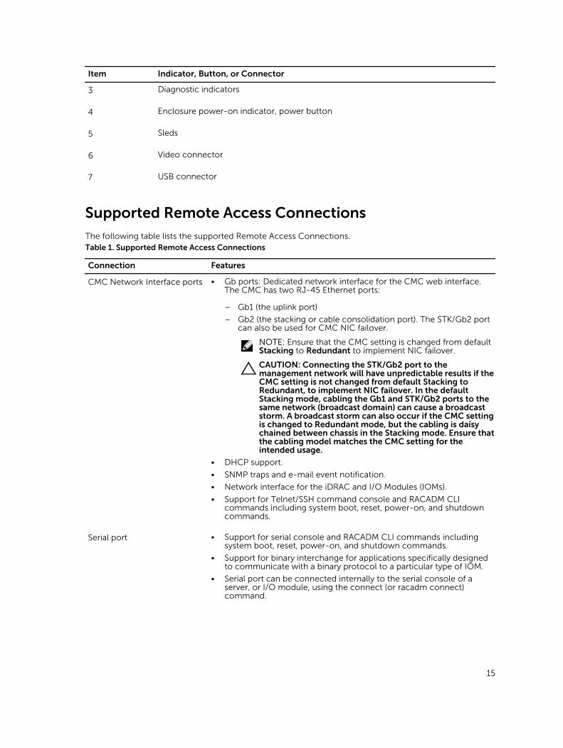
Item Indicator, Button, or Connector
3 Diagnostic indicators
4 Enclosure power-on indicator, power button
5 Sleds
6 Video connector
7 USB connector
Supported Remote Access Connections
The following table lists the supported Remote Access Connections.Table 1. Supported Remote Access Connections
Connection Features
CMC Network Interface ports • Gb ports: Dedicated network interface for the CMC web interface. The CMC has two RJ-45 Ethernet ports:
– Gb1 (the uplink port)
– Gb2 (the stacking or cable consolidation port). The STK/Gb2 port can also be used for CMC NIC failover.
NOTE: Ensure that the CMC setting is changed from default Stacking to Redundant to implement NIC failover.
CAUTION: Connecting the STK/Gb2 port to the management network will have unpredictable results if the CMC setting is not changed from default Stacking to Redundant, to implement NIC failover. In the default Stacking mode, cabling the Gb1 and STK/Gb2 ports to the same network (broadcast domain) can cause a broadcast storm. A broadcast storm can also occur if the CMC setting is changed to Redundant mode, but the cabling is daisy chained between chassis in the Stacking mode. Ensure that the cabling model matches the CMC setting for the intended usage.
• DHCP support.
• SNMP traps and e-mail event notification.
• Network interface for the iDRAC and I/O Modules (IOMs).
• Support for Telnet/SSH command console and RACADM CLI commands including system boot, reset, power-on, and shutdown commands.
Serial port • Support for serial console and RACADM CLI commands including system boot, reset, power-on, and shutdown commands.
• Support for binary interchange for applications specifically designed to communicate with a binary protocol to a particular type of IOM.
• Serial port can be connected internally to the serial console of a server, or I/O module, using the connect (or racadm connect) command.
15
Supported Platforms
The CMC supports the PowerEdge FX2 and FX2s chassis models. The supported platforms are PowerEdge FC630 and PowerEdge FM120x4. For information about compatibility with CMC, see the documentation for your device.
For the latest supported platforms, see the Dell Chassis Management Controller (CMC) Version 1.1 for Dell PowerEdge FX2/FX2s Release Notes available at dell.com/support/manuals.
Supported Web Browsers
For the latest information about supported web browsers, see the Dell Chassis Management Controller (CMC) Version 1.1 for Dell PowerEdge FX2/FX2s Release Notes located at dell.com/support/manuals.
Managing Licenses
The CMC features are available based on the license (CMC Express or CMC Enterprise) purchased. Only licensed features are available in the interfaces that allow you to configure or use CMC. For example, CMC Web interface, RACADM, WS-MAN, and so on. CMC license management and firmware update functionality is always available through CMC Web interface and RACADM.
Types of Licenses
The types of licenses offered are:
• 30 day evaluation and extension — The license expires after 30 days that can be extended for 30 days. Evaluation licenses are duration-based, and the timer runs when power is applied to the system.
• Perpetual — The license is bound to the service tag and is permanent.
Acquiring Licenses
Use any of the following methods to acquire the licenses:
• E-mail — License is attached to an e-mail that is sent after requesting it from the technical support center.
• Self-service portal — A link to the Self-Service Portal is available from CMC. Click this link to open the licensing Self-Service Portal on the internet from where you can purchase licenses. For more information, see the online help for the self-service portal page.
• Point-of-sale — License is acquired while placing the order for a system.
License Operations
Before you perform the license management tasks, make sure to acquire the licenses. For more information, see the Acquiring Licenses section and Overview and Feature Guide available at support.dell.com.
NOTE: If you have purchased a system with all the licenses pre-installed, then license management is not required.
You can perform the following licensing operations using CMC, RACADM, and WS-MAN for one-to-one license management, and Dell License Manager for one-to-many license management:
16
• View — View the current license information.
• Import — After acquiring the license, store the license in a local storage and import it into CMC using one of the supported interfaces. The license is imported if it passes the validation checks.
NOTE: For a few features, a CMC restart may be required to enable the features.
• Export — Export the installed license into an external storage device back up or to reinstall it after a service part is replaced. The file name and format of the exported license is <EntitlementID>.xml
• Delete — Delete the license that is assigned to a component if the component is missing. After the license is deleted, it is not stored in CMC and the base product functions are enabled.
• Replace — Replace the license to extend an evaluation license, change a license type such as an evaluation license with a purchased license, or extend an expired license.
• An evaluation license may be replaced with an upgraded evaluation license or with a purchased license.
• A purchased license may be replaced with an updated license or with an upgraded license. For more information, see Dell Software License Management Portal available at HTTPS://WWW.DELL.COM/SUPPORT/LICENSING/US/EN/19
• Learn More — Learn more about an installed license, or the licenses available for a component installed in the server.
NOTE: For the Learn More option to display the correct page, make sure that *.dell.com is added to the list of Trusted Sites in the Security Settings. For more information, see the Internet Explorer help documentation.
NOTE: If you try to install the PowerEdge FM120x4 license on PowerEdge FC630, the license installation fails. For more information on licensing refer Integrated Dell Remote Access Controller (iDRAC) User’s Guide .
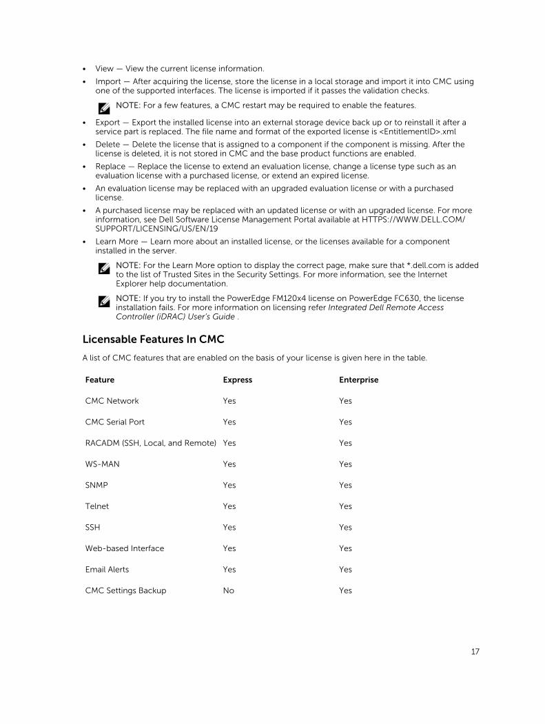
Licensable Features In CMC
A list of CMC features that are enabled on the basis of your license is given here in the table.
Feature Express Enterprise
CMC Network Yes Yes
CMC Serial Port Yes Yes
RACADM (SSH, Local, and Remote) Yes Yes
WS-MAN Yes Yes
SNMP Yes Yes
Telnet Yes Yes
SSH Yes Yes
Web-based Interface Yes Yes
Email Alerts Yes Yes
CMC Settings Backup No Yes
17
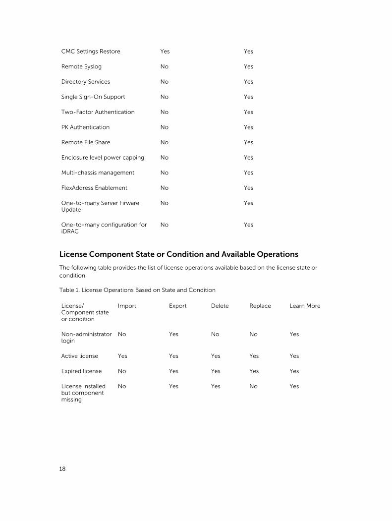
CMC Settings Restore Yes Yes
Remote Syslog No Yes
Directory Services No Yes
Single Sign-On Support No Yes
Two-Factor Authentication No Yes
PK Authentication No Yes
Remote File Share No Yes
Enclosure level power capping No Yes
Multi-chassis management No Yes
FlexAddress Enablement No Yes
One-to-many Server Firware Update
No Yes
One-to-many configuration for iDRAC
No Yes
License Component State or Condition and Available Operations
The following table provides the list of license operations available based on the license state or condition.
Table 1. License Operations Based on State and Condition
License/Component state or condition
Import Export Delete Replace Learn More
Non-administrator login
No Yes No No Yes
Active license Yes Yes Yes Yes Yes
Expired license No Yes Yes Yes Yes
License installed but component missing
No Yes Yes No Yes
18
Viewing Localized Versions of the CMC Web InterfaceTo view localized versions of the CMC web interface, read through your web browser's documentations. To view the localized versions, set the browser to the desired language.
Supported Management Console Applications
The CMC supports integration with Dell OpenManage Console. For more information, see the OpenManage Console documentation available at dell.com/support/manuals.
How to Use this User's Guide
The contents of this User's Guide enable you to perform the tasks by using:
• The Web interface: Only the task-related information is given here. For information about the fields and options, see the CMC for Dell PowerEdge FX2/FX2s Online Help that you can open from the Web interface.
• The RACADM commands: The RACADM command or the object that you must use is provided here. For more information about a RACADM command, see the Dell Chassis Management Controller for PowerEdge FX2/FX2s RACADM Command Line Reference Guide available at dell.com/support/manuals.
Other Documents You May Need
To access the documents from the Dell Support site. Along with this Reference Guide, you can access the following guides available at dell.com/support/manuals.
• The CMC FX2/FX2s Online Help provides information about using the Web interface. To access the Online Help, click Help on the CMC web interface.
• The Chassis Management Controller Version 1.1 for Dell PowerEdge FX2/FX2s RACADM Command Line Reference Guide provides information about using the FX2/FX2s–related RACADM features.
• The Dell Chassis Management Controller (CMC) for Dell PowerEdge FX2/FX2s Version 1.1 Release Notes provides last-minute updates to the system or documentation or advanced technical reference material intended for experienced users or technicians.
• The Integrated Dell Remote Access Controller 7 (iDRAC) User’s Guide provides information about installation, configuration, and maintenance of the iDRAC7 on managed systems.
• The Dell OpenManage Server Administrator’s User’s Guide provides information about installing and using Server Administrator.
• The Dell Update Packages User's Guide provides information about obtaining and using Dell Update Packages as part of your system update strategy.
• Dell systems management application documentation provides information about installing and using the systems management software.
The following system documents provide more information about the system in which CMC PowerEdege FX2/FX2s is installed:
• The safety instructions that came with your system provide important safety and regulatory information. For additional regulatory information, see the Regulatory Compliance home page at www.dell.com/regulatory_compliance. Warranty information may be included within this document or as a separate document.
19
• The setup placemat shipped with your system provides information about the initial system setup and configuration.
• The server module's Owner's Manual provides information about the server module's features and describes how to troubleshoot the server module and install or replace the server module's components. This document is available online at dell.com/poweredgemanuals.
• The rack documentation included with your rack solution describes how to install your system into a rack, if required.
• For the full name of an abbreviation or acronym used in this document, see the Glossary at dell.com/support/manuals.
• Systems management software documentation describes the features, requirements, installation, and basic operation of the software.
• Documentation for any components you purchased separately provides information to configure and install these options.
• Any media that ships with your system that provides documentation and tools for configuring and managing your system, including those pertaining to the operating system, system management software, system updates, and system components that you purchased with your system. For more information on the system, scan the Quick Resource Locator (QRL) available on your system and the system setup placemat that shipped with your system. Download the QRL application from your mobile platform to enable the application on your mobile device.
Updates are sometimes included with the system to describe changes to the system, software, and/or documentation. Always read the updates first, because they often supersede information in other documents.
Accessing documents from Dell support site
You can access the required documents in one of the following ways:
• Using the following links:
– For all Enterprise Systems Management documents — dell.com/softwaresecuritymanuals
– For Enterprise Systems Management documents — dell.com/openmanagemanuals
– For Remote Enterprise Systems Management documents — dell.com/esmmanuals
– For OpenManage Connections Enterprise Systems Management documents — dell.com/OMConnectionsEnterpriseSystemsManagement
– For Serviceability Tools documents — dell.com/serviceabilitytools
– For Client Systems Management documents — dell.com/clientsystemsmanagement
– For OpenManage Connections Client Systems Management documents — dell.com/connectionsclientsystemsmanagement
• From the Dell Support site:
a. Go to dell.com/support/home.
b. Under General support section, click Software & Security.
c. In the Software & Security group box, click the required link from the following:
– Enterprise Systems Management
– Remote Enterprise Systems Management
– Serviceability Tools
20

– Client Systems Management
– Connections Client Systems Management
d. To view a document, click the required product version.
• Using search engines:
– Type the name and version of the document in the search box.
21
2Installing and Setting Up CMCThis section provides information about how to install your CMC hardware, establish access to CMC, configure your management environment to use CMC, and guides you through the tasks for configuring a CMC:
• Set up initial access to CMC.
• Access CMC through a network.
• Add and configure CMC users.
• Update CMC firmware.
Installing CMC Hardware
The CMC is pre-installed on your chassis and hence no installation is required.
Checklist To Set up Chassis
The following tasks enable you to accurately setup the chassis:
1. The CMC and the management station, where you use your browser, must be on the same network, which is called the management network. Connect an Ethernet network cable from the port labelled GB1 to the management network.
Management Network: CMC and the iDRAC (on each server) and the network management ports for the switch I/O module are connected to a common internal network in the PowerEdge FX2/FX2s chassis. This allows the management network to be isolated from the server data network.
Application Network: Access to the managed servers is accomplished through network connections to the I/O module (IOM). This allows the application network to be isolated from the management network. It is important to separate this traffic for uninterrupted access to chassis management.
NOTE: It is recommended to isolate chassis management from the data network. Due to the potential of traffic on the data network, the management interfaces on the internal management network can be saturated by traffic intended for servers. This results in CMC and iDRAC communication delays. These delays may cause unpredictable chassis behavior, such as CMC displaying iDRAC as offline even when it is up and running, which in turn causes other unwanted behavior. If physically isolating the management network is impractical, the other option is to separate CMC and iDRAC traffic to a separate VLAN. CMC and individual iDRAC network interfaces can be configured to use a VLAN.
2. The STK/Gb2 port can also be used for CMC NIC failover. Ensure that the CMC setting is changed from default Stacking to Redundant to implement NIC failover. For more information, see Configuring Management Port 2
22
CAUTION: Connecting the STK/Gb2 port to the management network will have unpredictable results if the CMC setting is not changed from default Stacking to Redundant, to implement NIC failover. In the default Stacking mode, cabling the Gb1 and STK/Gb2 ports to the same network (broadcast domain) can cause a broadcast storm. A broadcast storm can also occur if the CMC setting is changed to Redundant mode, but the cabling is daisy chained between chassis in the Stacking mode. Ensure that the cabling model matches the CMC setting for the intended usage.
3. Install the I/O module in the chassis and connect the network cable to the I/O module.
4. Insert the servers in the chassis.
5. Connect the chassis to the power source.
6. To power on the chassis, press the power button or use the following interfaces after completing the task 6. Using the Web interface, go to Chassis Overview → Power → Control → Power Control Options → Power On System. Click Apply.
You can also power on the chassis using the command line interface, use racadm chassisaction powerup command to accomplish it.
NOTE: Do not turn on the servers.
7. The default CMC network configuration is Static with the CMC IP address 192.168.0.120. If you want to change the network configuration to DHCP, connect a serial cable to serial port on the CMC. For more information on serial connection, refer to Serial interface/protocol setup in Using Remote Access Software From a Management Station section.
After the serial connection is established, login and use the command racadm setniccfg —d to
change the network configuration to DHCP. CMC takes 30 to 60 seconds approximately to obtain the IP address from the DHCP server.
To view the DHCP assigned CMC IP address, use one of the following methods:
• To view CMC IP address using serial connection with CMC, perform the following steps:
1. Connect one end of the serial null modem cable to the serial connector on the back of the chassis.
2. Connect the other end of the cable to the management system serial port.
3. After the connection is established, login to CMC using default root account credentials.
4. Run the racadm getniccfg command.
In the output displayed, search for Current IP Address.
• To view CMC IP address by connecting the server using KVM, perform the following steps:
1. Connect to a server in the chassis using KVM.
NOTE: For more details on how to connect a server through KVM, see Accessing Server Using KVM.
2. Turn on the server.
3. Make sure the server is set to boot in Unified Extensible Firmware Interface (UEFI) mode.
4. Press F2 to access the System Setup page.
5. In the System Setup page, click iDRAC Settings → System Summary.
The CMC IP address is displayed in the Chassis Management Controller section.
For more information about iDRAC Settings page in the iDRAC GUI, see the Dell Integrated Dell Remote Access Controller (iDRAC) User’s Guide .
8. Connect to the CMC IP address by using a web browser by typing the default root account credential.
23
9. Configure iDRAC network settings as required. by default, iDRAC LAN is enabled with static IP configured. To determine the default static IP address with an Enterprise license, go to Server Overview → Setup → iDRAC. You can also determine the static IP address with an Express license. Go to Server Overview → Server-Slot → Setup → iDRAC.
10. Provide the IO module with an external management IP address(if applicable) in the CMC web interface. You can get the IP address by clicking I/O Module Overview, and then clicking Setup.
11. Connect to each iDRAC through the web interface using default root account credential to complete any necessary configuration.
12. Turn on the servers and install the operating system.
NOTE: The default local account credential is root (user name) and calvin (user password).
Using Remote Access Software From a Management Station
You can access CMC from a management station using various remote access software. Here is a list of remote access softwares by Dell which is available from your Operating System.
Interface/Protocol Description
Serial CMC supports a serial text console that can be launched using any terminal emulation software. Following are couple of examples of terminal emulation software that can used to connect to CMC.
• Linux Minicom
• Hilgraeve’s HyperTerminal for Windows
Connect one end of the serial null modem cable (present at both ends) to the serial connector on the back of the chassis. Connect the other end of the cable to management station serial port. For more information on connecting cables, refer to the back panel of the chassis in Chassis Overview section.
Configure your terminal emulation software with the following parameters:
• Baud rate: 115200
• Port: COM1
• Data: 8 bit
• Parity: None
• Stop: 1 bit
• Hardware flow control: Yes
• Software flow control: No
Remote RACADM CLI Remote RACADM is a client utility that runs on a management station. It uses the out-of-band network interface to run RACADM commands on the managed system and uses the HTTPs channel. The –r option runs the RACADM command over a network, it requires CMC IP, username and password.
24

To use remote RACADM from your management station, install remote RACADM using the Dell Systems Management Tools and Documentation DVD that is available with your system. For more information on Remote RACADM
Web Interface Provides remote access to CMC using a graphical user interface. The Web interface is built into the CMC firmware and is accessed through the NIC interface from a supported web browser on the management station. For a list of supported Web browsers, see the Supported Browsers section in the Dell System Software Support Matrix at dell.com/support/manuals.
Telnet Provides command line access to CMC through the network. The RACADM command line interface and the connect command, which is used to connect to the serial console of a server or IO module, are available from the CMC command line.
NOTE: Telnet is not a secure protocol and is disabled by default. Telnet transmits all data, including passwords in plain text.
SNMP Simple Network Management Protocol (SNMP) is a set of protocol definitions for managing devices on the networks. The CMC provides access to SNMP, which allows you to use SNMP tools to query the CMC for Systems Management information. The CMC MIB file can be downloaded from the CMC Web interface, go to Chassis Overview → Network → Services → SNMP. See the Dell OpenManage SNMP Reference Guide for more information about the CMC MIB.
The following example show how the net-snmp snmpget command can be used to get the chassis service tag from the CMC.
snmpget -v 1 -c <CMC community name> <CMC IP address>.1.3.6.1.4.1.674.10892.2.1.1.6.0
WS-MAN The WSMAN Services is based on the Web Services for Management (WSMAN) protocol to perform one-to-many systems management tasks. You can use WS-MAN client such as WinRM client (Windows) or the OpenWSMAN client (Linux) to use the LC-Remote Services functionality. You can also use Power Shell and Python script the WS-MAN interface.
WSMAN is a Simple Object Access Protocol (SOAP)–based protocol used for systems management. CMC uses WS–Management to convey Distributed Management Task Force
25
(DMTF) Common Information Model (CIM)–based management information. The CIM information defines the semantics and information types that can be modified in a managed system.
The CMC WS-MAN implementation uses SSL on port 443 for transport security, and supports basic authentication. The data available through WS-Management is provided by CMC instrumentation interface mapped to the DMTF profiles and extension profiles.
NOTE: The SSL port used for transport security is the same as the CMC HTTPS port.
For more information, see:
• MOFs and Profiles — delltechcenter.com/page/DCIM.Library
• DTMF Web site — dmtf.org/standards/profiles/
• WS-MAN Release notes file.
• www.wbemsolutions.com/ws_management.html
• DMTF WS-Management Specifications: www.dmtf.org/standards/wbem/wsman
For client connection using Microsoft WinRM, the minimum required version is 2.0. For more information, refer to the Microsoft article, <support.microsoft.com/kb/968929>.
Launching CMC Using Other Systems Management Tools
You can also launch CMC from the Dell Server Administrator or Dell OpenManage Essentials.
To access CMC interface using Dell Server Administrator, launch Server Administrator on your
management station. In the left pane of the Server Administrator home page, click System → Main System Chassis → Remote Access Controller. For more information, see the Dell Server Administrator User’s Guide at dell.com/support/manuals.
Remote RACADM Installation
To use remote RACADM from your management station, install remote RACADM using the Dell Systems Management Tools and Documentation DVD that is available with your system. This DVD includes the following Dell OpenManage components:
• DVD root — Contains the Dell Systems Build and Update Utility.
• SYSMGMT — Contains the systems management software products including Dell OpenManage Server Administrator.
• Docs — Contains documentation for systems, systems management software products, peripherals, and RAID controllers.
• SERVICE — Contains the tools required to configure your system, and delivers the latest diagnostics and Dell-optimized drivers for your system.
26
For information about installing Dell OpenManage software components, see the Dell OpenManage Installation and Security User's Guide available at dell.com/support/manuals. You can also download the latest version of the Dell DRAC Tools from support.dell.com.
Installing Remote RACADM on a Windows Management Station
If you are using the DVD, run <path>\SYSMGMT\ManagementStation\windows\DRAC\<.msi file name>
If you have downloaded the software from support.dell.com:
1. Extract the downloaded file and execute the .msi file provided.
Depending on the version downloaded, the file will be named DRAC.msi, RACTools.msi, or RACTools64Bit.msi.
2. Accept the license agreement. Click Next.
3. Select the location where it is to be installed. Click Next.
4. Click Install.
The installing window appears.
5. Click Finish.
Open an administrative command prompt, type racadm and press Enter. If you get the RACADM help instructions, it implies that the software is installed correctly.
Installing Remote RACADM on a Linux Management Station
1. Log in as root to the system running a supported Red Hat Enterprise Linux or SUSE Linux Enterprise Server operating system where you want to install the managed system components.
2. Insert the Dell Systems Management Tools and Documentation DVD into the DVD drive.
3. To mount the DVD to a required location, use the mount command or a similar command.
NOTE: On the Red Hat Enterprise Linux 5 operating system, DVDs are auto-mounted with the -noexec mount option. This option does not allow you to run any executable from the DVD.
You need to mount the DVD-ROM manually, and then run the commands.
4. Navigate to the SYSMGMT/ManagementStation/linux/rac directory. To install the RAC software, type the following command:
rpm -ivh *.rpm5. For help about the RACADM command, type racadm help after you run the previous commands.
For more information about RACADM, see the Chassis Management Controller for Dell PowerEdge FX2/FX2s RACADM Command Line Reference Guide.
NOTE: When using the RACADM remote capability, you must have the 'write' permission on the folders where you are using the RACADM subcommands, involving the file operations. For example, racadm getconfig -f <file name>.
Uninstalling Remote RACADM From a Linux Management Station
1. Log in as root to the system where you want to uninstall the management station features.
2. Run the following rpm query command to determine which version of the DRAC tools is installed:
rpm -qa | grep mgmtst-racadm3. Verify the package version to be uninstalled and uninstall the feature by using the rpm -e rpm -qa
| grep mgmtst-racadm command.
27
Configuring a Web Browser
You can configure and manage CMC, servers, and modules installed in the chassis through a web browser. See the “Supported Browsers" section in the Dell Systems Software Support Matrix at dell.com/support/manuals.
The CMC and the management station where you use your browser must be on the same network, which is called the management network. On the basis of your security requirements, the management network can be an isolated and highly secure network.
NOTE: Make sure that the security measures on the management network such as firewalls and proxy servers, do not prevent your web browser from accessing the CMC.
Some browser features can interfere with connectivity or performance, especially if the management network does not have a route to the Internet. If your management station is running on a Windows operating system, some Internet Explorer settings can interfere with connectivity, even though you use a command line interface to access the management network.
NOTE: To address security issues, Microsoft Internet Explorer strictly monitors the time on its cookie management. To support this, the time on your computer that runs Internet Explorer must be synchronized with the time on the CMC.
Proxy Server
To browse through a proxy server that does not have access to the management network, you can add the management network addresses to the exception list of the browser. This instructs the browser to bypass the proxy server while accessing the management network.
Microsoft Phishing Filter
If the Microsoft Phishing Filter is enabled in Internet Explorer on your management system, and your CMC does not have Internet access, accessing CMC may be delayed by a few seconds. This delay can happen if you are using the browser or another interface such as remote RACADM. To disable the phishing filter:
1. Start Internet Explorer.
2. Click Tools → Phishing Filter, and then click Phishing Filter Settings.
3. Select the Disable Phishing Filter option and click OK.
Downloading Files From CMC With Internet Explorer
When you use Internet Explorer to download files from the CMC, you may experience problems when the Do not save encrypted pages to disk option is not enabled.
To enable the Do not save encrypted pages to disk option:
1. Start Internet Explorer.
2. Click Tools → Internet Options → Advanced.
3. In the Security section, select the Do not save encrypted pages to disk option.
Enabling Animations In Internet Explorer
When transferring files to and from the web interface, a file transfer icon spins to show transfer activity. While using Internet explorer, you have to configure the browser to play animations.
28
To configure Internet Explorer to play animations:
1. Start Internet Explorer.
2. Click Tools → Internet Options → Advanced.
3. Go to the Multimedia section, and then select the Play animations in web pages option.
Downloading and Updating CMC Firmware
To download the CMC firmware, see Downloading CMC Firmware.
To update the CMC firmware, see Updating CMC Firmware.
Setting Chassis Physical Location and Chassis Name
You can set the chassis location in a data center and the chassis name to identify the chassis on the network (default name is cmc-“Service Tag”). For example, an SNMP query on the chassis name returns the name you configure.
Setting Chassis Physical Location and Chassis Name Using Web Interface
To set the chassis location and chassis name using the CMC web interface:
1. In the left pane, go to Chassis Overview, and then click Setup.
2. On the General Chassis Settings page, type the location properties and the chassis name. For more information about setting chassis properties, see the CMC Online Help.
NOTE: The Chassis Location field is optional. It is recommended to use the Data Center, Aisle, Rack, and Rack Slot fields to indicate the physical location of the chassis.
3. Click Apply. The settings are saved.
Setting Chassis Physical Location and Chassis Name Using RACADM
To set the chassis name, location, date, and time by using the command line interface, see the setsysinfo and setchassisname commands.
For example racadm setsysinfo —c chassisname or racadm setsysinfo —c chassislocation
For more information, see the Chassis Management Controller for PowerEdge FX2/FX2s RACADM Command Line Reference Guide.
Setting Date and Time on CMC
You can manually set the date and time, or you can synchronize the date and time with a Network Time Protocol (NTP) server.
Setting Date and Time on CMC Using CMC Web Interface
To set the date and time on CMC:
1. In the left pane, click Chassis Overview → Setup → Date/Time.
2. To synchronize the date and time with a Network Time Protocol (NTP) server, on the Date/Time page, select Enable NTP and specify up to three NTP servers. To manually set the date and time, clear the Enable NTP option, and then edit the Date and Time fields.
3. Select the Time Zone from the drop-down menu, and then click Apply.
29
Setting Date and Time on CMC Using RACADM
To set the date and time using the command line interface, see the config command and cfgRemoteHosts database property group sections in the Chassis Management Controller for
PowerEdge FX2/FX2s RACADM Command Line Reference Guide available at dell.com/support/manuals.
For example racadm setractime -l 20140207111030.
To read the date and time use racadm getractime command.
Configuring LEDs to Identify Components on the Chassis
You can enable the LEDs of components (chassis, servers, and I/O Modules) to blink so that you can identify the component on the chassis.
NOTE: To modify these settings, you must have the Debug Administrator privilege on a CMC.
Configuring LED Blinking Using CMC Web Interface
To enable blinking for one, multiple, or all component LEDs:
• In the left pane, go to any of the following pages:
– Chassis Overview → Troubleshooting.
– Chassis Overview → Chassis Controller → Troubleshooting.
– Chassis Overview → Server Overview → Troubleshooting.
NOTE: Only servers can be selected on this page.
To enable blinking of a component LED, select the respective component , and then click Blink. To disable blinking of a component LED, deselect the server, and then click Unblink.
Configuring LED Blinking Using RACADM
Open a serial/Telnet/SSH text console to CMC, log in, and type:
racadm setled -m <module> [-l <ledState>], where <module> specifies the module whose
LED you want to configure. Configuration options:
• server-n where n = 1-4 (PowerEdge FM120x4), and server-nx where n = 1–4 and x = a to b (PowerEdge FC630).
• switch-1• cmc-active
and <ledState> specifies whether or not the LED should blink. Configuration options:
• 0 — not blinking (default)
• 1 — blinking
Configuring CMC Properties
You can configure CMC properties such as power budgeting, network settings, users, and SNMP and email alerts using the web interface or RACADM commands.
30
Configuring Front Panel
You can use the front panel page to configure:
• Power button
• KVM
Configuring Power Button
To configure the chassis power button:
1. In the left pane, click Chassis Overview → Front Panel → Setup.
2. On the Front Panel Configuration page, under the Power Button Configuration section, select the Disable Chassis Power Button option, and then click Apply.
The chassis power button is disabled.
Accessing a Server Using KVM
To map a Server to KVM from Web Interface:
1. Connect a monitor to the video connector and a keyboard to USB connector located on the front of the chassis.
2. In the left pane, click Chassis Overview → Front Panel → Setup.
3. On the Front Panel Configuration page, under the KVM Configuration section, select Enable KVM Mapping option.
4. On the Front Panel Configuration page, under the KVM Configuration section, for KVM Mapped option, select the desired server from the drop down list.
5. Click Apply.
To map a Server to KVM using racadm, useracadm config -g cfgKVMInfo -o cfgKvmMapping [server slot #] command.
To view the current KVM mapping using racadm, use racadm getconfig -g cfgKVMInfo.
Configuring Chassis Management at Server Mode
This feature provides the ability to manage and monitor the chassis shared components and chassis nodes as rack servers. When this feature is enabled, you can manage and monitor the chassis fans, power supplies, temperature sensors, update and configure the CMC firmware through the following components:
• iDRAC
• Blade Server Operating System
• Lifecycle Controller
Configuring Chassis Management at Server Using CMC Web Interface
To enable chassis management at server mode:
1. In the left pane, click Chassis Overview → Setup → General.
2. In the General Chassis Settings page, from the Chassis Management at Server Mode drop-down, select one of the following modes:
31
• None — This mode does not enable you to monitor or manage the chassis component through iDRAC, OS, or Lifecycle Controller.
• Monitor — This mode enables you to monitor the chassis components but you cannot perform any firmware update through iDRAC, OS, or Lifecycle Controller.
• Manage and Monitor — This mode enables you to monitor the chassis components and update the CMC firmware using DUP through iDRAC, OS, or Lifecycle Controller.
Configuring Chassis Management at Server Mode Using RACADM
To enable the Chassis Management at server using RACADM, use the following commands:
• To disable Chassis Management at Server mode, use:
racadm config –g cfgRacTuning – cfgRacTuneChassisMgmtAtServer 0• To change Chassis Management at Server mode to monitor, use:
racadm config –g cfgRacTuning – cfgRacTuneChassisMgmtAtServer 1• To change Chassis Management at server mode to manage and monitor, use:
racadm config –g cfgRacTuning – cfgRacTuneChassisMgmtAtServer 2
32
3Logging in to CMCYou can log in to CMC as a CMC local user, as a Microsoft Active Directory user, or as an LDAP user. You can also log in using Single Sign-On or a Smart Card.
Configure Public Key Authentication Over SSH
You can configure up to six public keys that can be used with the service username over an SSH interface. Before adding or deleting public keys, make sure to use the view command to see what keys
are already set up, so that a key is not accidentally overwritten or deleted. The service username is a special user account that can be used when accessing the CMC through SSH. When the PKA over SSH is set up and used correctly, you need not enter username or passwords to log in to the CMC. This can be very useful to set up automated scripts to perform various functions.
NOTE: There is no GUI support for managing this feature, you can use only the RACADM.
When adding new public keys, make sure that the existing keys are not already at the index, where the new key is added. CMC does not perform checks to ensure previous keys are deleted before a new one is added. As soon as a new key is added, it is automatically in effect as long as the SSH interface is enabled.
When using the public key comment section of the public key, remember that only the first 16 characters are utilized by the CMC. The public key comment is used by the CMC to distinguish SSH users when using the RACADM getssninfo command, because all the PKA users use the service username to log in.
For example, if two public keys are set up one with comment PC1 and one with comment PC2:
racadm getssninfoType User IP Address LoginDate/TimeSSH PC1 x.x.x.x 06/16/200909:00:00SSH PC2 x.x.x.x 06/16/200909:00:00For more information about the sshpkauth, see the Chassis Management Controller for PowerEdge
FX2/FX2s Command Line Reference Guide.
Generating Public Keys for Systems Running Windows
Before adding an account, a public key is required from the system that accesses the CMC over SSH. There are two ways to generate the public/private key pair: using PuTTY Key Generator application for clients running Windows or ssh-keygen CLI for clients running Linux.
This section describes simple instructions to generate a public/private key pair for both applications. For additional or advanced usage of these tools, see the application Help.
33
To use the PuTTY Key Generator to create a basic key for clients running Windows:
1. Start the application and select SSH-2 RSA or SSH-2 DSA for the type of key to generate (SSH-1 is not supported).
2. Enter the number of bits for the key. RSA key size should be between 768 and 4096 and the recommended DSA key size is 1024.
NOTE:
• CMC may not display a message if you add keys less than 768 or greater than 4096, but when you try to log in with these keys, it fails.
• For DSA keys greater than 2048, use the following racadm command. CMC accepts RSA keys up to key strength 4096, but the recommended key strength is 1024.
racadm -r 192.168.8.14 -u <default root account username> -p <default root account password> sshpkauth -i svcacct -k 1 -p 0xfff -f dsa_2048.pub
3. Click Generate and move the mouse in the window as directed.
After the key is created, you can modify the key comment field.
You can also enter a passphrase to make the key secure. Ensure that you save the private key.
4. You have two options for using the public key:
• Save the public key to a file to upload later.
• Copy and paste the text from the Public key for pasting window when adding the account using the text option.
Generating Public Keys for Systems Running Linux
The ssh-keygen application for Linux clients is a command line tool with no graphical user interface. Open a terminal window and at the shell prompt type:
ssh-keygen –t rsa –b 1024 –C testingwhere,
–t must be dsa or rsa.
–b specifies the bit encryption size between 768 and 4096.
–c allows modifying the public key comment and is optional.
The < passphrase > is optional. After the command completes, use the public file to pass to the
RACADM for uploading the file.
Accessing CMC Web InterfaceBefore you log in to CMC using the web interface, make sure that you have configured a Supported Web Browser and the user account is created with the required privileges.
NOTE: If you are using Microsoft Internet Explorer, connect using a proxy, and if you see the error The XML page cannot be displayed, you must disable the proxy to continue.
To access the CMC web interface:
1. Open a web browser supported on your system.
34
For the latest information on supported web browsers, see the Dell Systems Software Support Matrix located at dell.com/support/manuals.
2. In the Address field, type the following URL, and then press <Enter>:
• To access CMC using IPv4 address: https://<CMC IP address> If the default HTTPS port number (port 443) was changed, type: https://<CMC IP address>:<port number>
• To access CMC using IPv6 address: https://[<CMC IP address>] If the default HTTPS port number (port 443) was changed, type: https://[<CMC IP address>]:<port number>, where <CMC IP address> is the IP address for CMC and <port
number> is the HTTPS port number.
The CMC Login page appears.
NOTE: While using IPv6, you must enclose the CMC IP address in parenthesis ([ ]).
Logging Into CMC as a Local User, Active Directory User, or LDAP UserTo log in to CMC, you must have a CMC account with the Log In to CMC privilege. The default root account is the default administrative account that ships with CMC.
NOTE: For added security, it is strongly recommended that you change the default password of the root account during initial setup.
NOTE: When Certificate Validation is enabled, FQDN of the system should be provided. If certificate validation is enabled and IP address is provided for the Domain Controller, then the login will fail.
CMC does not support extended ASCII characters, such as ß, å, é, ü, or other characters used primarily in non-English languages.
To log in as a local user, Active Directory user, or LDAP user.
1. In the Username field, type your user name:
• CMC user name: <user name>
NOTE: The CMC user name can contain only alphanumeric characters and certain special characters. The at (@) symbol and following special characters are not supported:
– Forward slash (/)
– Backward slash (/)
– Semicolon (;)
– Backward Quote (`)
– Quotations (“)
• Active Directory user name: <domain>\<user name>, <domain>/<user name> or <user>@<domain>.
• LDAP user name: <user name>
NOTE: This field is case-sensitive.
2. In the Password field, type the user password.
NOTE: For Active Directory user, the Username field is case-sensitive.
3. In the Domain field, from the drop-down menu, select the required domain.
35
4. Optionally, select a session timeout. This is the duration for which you can stay logged in with no activity before you are automatically logged out. The default value is the Web Service Idle Timeout.
5. Click OK.
You are logged into CMC with the required user privileges.
You cannot log in to the Web interface with different user names in multiple browser windows on a single workstation.
Logging in to CMC Using a Smart CardTo use this feature, you must have an Enterprise License. You can log in to CMC using a smart card. Smart cards provide Two Factor Authentication (TFA) that provide two-layers of security:
• Physical smart card device.
• Secret code such as a password or PIN.
Users must verify their credentials using the smart card and the PIN.
NOTE: You cannot use the IP address to log in to CMC using the Smart Card login. Kerberos validates your credentials based on the Fully Qualified Domain Name (FQDN).
Before you log in as an Active Directory user using a Smart Card, make sure to:
• Upload a Trusted Certificate Authority (CA) certificate (CA-signed Active Directory certificate) to CMC
• Configure the DNS server.
• Enable Active Directory login.
• Enable Smart Card login.
To log in to CMC as an Active Directory user using a smart card:
1. Log in to CMC using the link https://<cmcname.domain-name>.
The CMC Login page is displayed asking you to insert a smart card.
NOTE: If you changed the default HTTPS port number (port 80), access the CMC web page using <cmcname.domain-name>:<port number>, where cmcname is the CMC host name
for CMC, domain-name is the domain name, and port number is the HTTPS port number.
2. Insert the smart card and click Login.
The PIN dialog box is displayed.
3. Type the PIN and click Submit.
NOTE: If the smart card user is present in Active Directory, an Active Directory password is not required. Else, you have to log in by using an appropriate username and password.
You are logged in to CMC with your Active Directory credentials.
Logging Into CMC Using Single Sign-onWhen Single Sign-On (SSO) is enabled, you can log in to CMC without providing your domain user authentication credentials, such as user name and password. To use this feature, you must have an Enterprise License.
NOTE: You cannot use the IP address to log in to the SSO. Kerberos validates your credentials against the Fully Qualified Domain Name (FQDN).
36
Before logging in to CMC using SSO, make sure that:
• You have logged in to your system using a valid Active Directory user account.
• Single Sign-On option is enabled during the Active Directory configuration.
To log in to CMC using SSO:
1. Log in to the client system using your network account.
2. Access the CMC web interface by using: https://<cmcname.domain-name>For example, cmc-6G2WXF1.cmcad.lab,, where cmc-6G2WXF1 is the cmc-name and cmcad.lab is the domain name.
NOTE: If you have changed the default HTTPS port number (port 80), access the CMC web interface using <cmcname.domain-name>:<port number>, where the cmcname is the CMC
host name for CMC, domain-name is the domain name, and port number is the HTTPS port number.
CMC logs you in, using the Kerberos credentials that were cached by your browser when you logged in using your valid Active Directory account. If the login is unsuccessful, the browser is redirected to the normal CMC login page.
NOTE: If you are not logged in to the Active Directory domain and are using a browser other than Internet Explorer, the login is unsuccessful and the browser displays a only blank page.
Logging In To CMC Using Serial, Telnet, Or SSH ConsoleYou can log in to CMC through a serial, Telnet, or SSH connection.
After you configure your management station terminal emulator software, perform the following tasks to log in to CMC:
1. Connect to CMC using your management station terminal emulation software.
2. Type your CMC user name and password, and then press <Enter>.
You are logged in to CMC.
Logging in to CMC Using Public Key Authentication
You can log in to the CMC over SSH without typing a password. You can also send a single RACADM command as a command line argument to the SSH application. The command line options behave similar to the remote RACADM, because the session ends after the command is completed.
Before logging in to CMC over SSH, make sure that the public keys are uploaded. To use this feature, you must have an Enterprise License.
For example:
• Logging in: ssh service@<domain> or ssh service@<IP_address>, where IP_address is the CMC IP address.
• Sending RACADM commands: ssh service@<domain> racadm getversion and ssh service@<domain> racadm getsel
When you log in using the service account, if a passphrase was set up when creating the public or private key pair, you may be prompted to enter that passphrase again. If the passphrase is used with the keys,
37
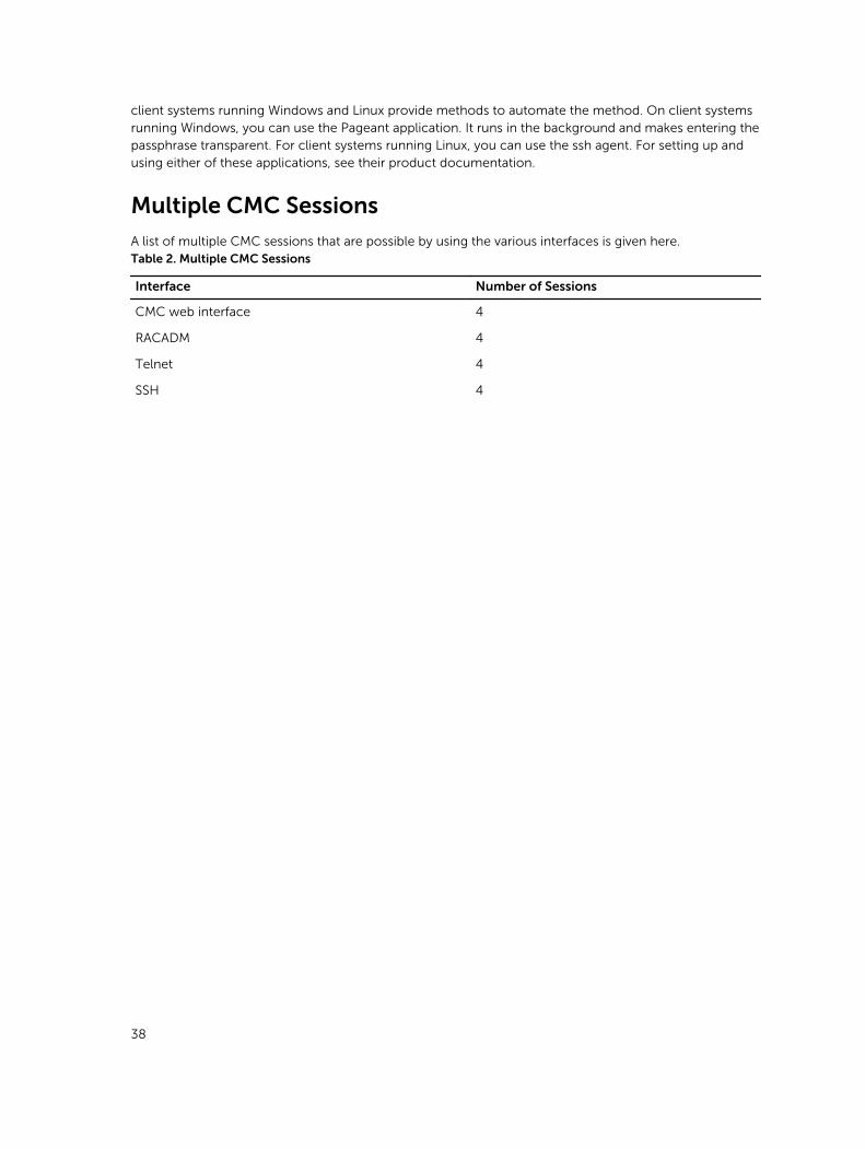
client systems running Windows and Linux provide methods to automate the method. On client systems running Windows, you can use the Pageant application. It runs in the background and makes entering the passphrase transparent. For client systems running Linux, you can use the ssh agent. For setting up and using either of these applications, see their product documentation.
Multiple CMC Sessions
A list of multiple CMC sessions that are possible by using the various interfaces is given here.Table 2. Multiple CMC Sessions
Interface Number of Sessions
CMC web interface 4
RACADM 4
Telnet 4
SSH 4
38
4Updating FirmwareYou can update firmware for:
• The CMC
• Chassis infrastructure
• I/O Module
• PERC
• Expander and HDD
You can update firmware for the following server components:
• BIOS
• iDRAC7 on FM120x4 (12th generation of servers)
• iDRAC8 on FC630 (13th generation of servers)
• Lifecycle Controller
• 32–bit diagnostics
• Operating System Drivers Pack
• Network Interface Controllers
• RAID controllers
Signed CMC Firmware Image
The CMC firmware includes a signature. The CMC firmware performs a signature verification step to ensure the authenticity of the uploaded firmware. The firmware update process is successful only if the firmware image is authenticated by CMC to be a valid image from the service provider and has not been altered. The firmware update process is stopped if CMC cannot verify the signature of the uploaded firmware image. A warning event is then logged and an appropriate error message is displayed.
When you try to upgrade CMC firmware version, CMC Firmware Update Process verifies the firmware image in the selected version for the signature from the service provider. The firmware update is stopped, if the signature is not found or if the verification of the image is not successful. A warning event is logged and an appropriate error message is displayed.
When a firmware downgrade to a earlier version is attempted, CMC Firmware Update Process verifies the firmware image in the earlier versions for the signature from the service provider. The firmware downgrade is stopped, if the computed signature of the earlier version is not recognized by the current CMC firmware. CMC firmware logs a warning event and an appropriate error message is displayed.
39
Downloading CMC Firmware
Before beginning the firmware update, download the latest firmware version from support.dell.com, and save it to your local system.
It is recommended to follow the following update order while updating firmware for the chassis:
• Blade components firmware
• CMC firmware
• Chassis infrastructure firmware
Viewing Currently Installed Firmware Versions
You can view the currently installed firmware versions using the CMC web interface or RACADM.
Viewing Currently Installed Firmware Versions Using CMC Web Interface
In the CMC web interface, go to any of the following pages to view the current firmware versions:
• Chassis Overview → Update
• Chassis Overview → Chassis Controller → Update
• Chassis Overview → Server Overview → Server Component Update
The Firmware Update page displays the current version of the firmware for each listed component and allows you to update the firmware to the latest version.
If the chassis contains an earlier generation server, whose iDRAC is in recovery mode or if CMC detects that iDRAC has corrupted firmware, then the earlier generation iDRAC is also listed on the Firmware Update page.
Viewing Currently Installed Firmware Versions Using RACADM
You can view the currently installed firmware versions using racadm getversion command. For more
information about other RACADM commands, see the Dell Chassis Management Controller for PowerEdge FX2/FX2s RACADM Command Line Reference Guide.
Updating the CMC Firmware
You can update the CMC firmware using web interface or RACADM. The firmware update, by default, retains the current CMC settings.
NOTE: To update firmware on CMC, you must have the Chassis Configuration Administrator privilege.
NOTE: You cannot update the CMC firmware if the firmware image file does not contain a verification signature or it contains a verification signature, which is not valid or corrupted.
NOTE: You cannot downgrade the CMC firmware to an earlier version if the computed signature of that earlier version is not recognized by the current CMC firmware.
If a Web user interface session is used to update system component firmware, the Idle Timeout (0, 60–10800) setting must be set to a higher value to accommodate the file transfer time. In some cases, the
40

firmware file transfer time may be as high as 30 minutes. To set the idle timeout value, see Configuring Services.
During CMC firmware updates, it is normal for some or all of the fan units in the chassis to rotate at 100% speed.
To avoid disconnecting other users during a reset, notify authorized users who may log in to CMC and check for active sessions on the Sessions page. To open the Sessions page, click Chassis Overview in the left pane, click Network, and then click the Sessions.
When transferring files to and from CMC, the file transfer icon spins during the transfer. If your icon is not animated, make sure that your browser is configured to allow animations. For more information about allowing animations in the browser, see Allow Animations in Internet Explorer.
Updating CMC Firmware Using Web Interface
To update the CMC firmware using the CMC web interface:
1. In the left pane, go to any of the following pages:
• Chassis Overview → Update
• Chassis Overview → Chassis Controller → Update
2. On the Firmware Update page, in the CMC Firmware section, select the required components under the Update Targets column for the CMC you want to update, and then click Apply CMC Update.
3. In the Firmware Image field, enter the path to the firmware image file on the management station or shared network, or click Browse to browse through to the file location. The default name of the CMC firmware image file is fx2_cmc.bin.
4. Click Begin Firmware Update, and then click Yes. The Firmware Update Progress section provides firmware update status information. A status indicator displays on the page while the image file is uploaded. File transfer time varies based on the connection speed. When the internal update process begins, the page automatically refreshes and the Firmware update timer is displayed. For more information about the various firmware status, see Online Help.
5. For the CMC, during the final phases of the firmware update process, the browser session and connection with CMC is lost temporarily because the CMC is not connected to the network. You must log in after a few minutes, when the CMC has restarted. After CMC resets, the new firmware version is displayed on the Firmware Update page.
NOTE: After the firmware update, delete the files from the web browser cache. For instructions about clearing the browser cache, see the web browser’s online help.
Additional instructions:
• During a file transfer, do not click the Refresh icon or navigate to another page.
• To cancel the process, select the Cancel File Transfer and Update option. This option is available only during file transfer.
• The Update State field displays the firmware update status.
NOTE: The update process may take several minutes.
Updating CMC Firmware Using RACADM
To update CMC firmware using RACADM, use the fwupdate subcommand.
For example, racadm fwupdate <options> <firmware image>.
41
For more information about RACADM commands, see Chassis Management Controller for PowerEdge FX2/FX2s RACADM Command Line Reference Guide.
Updating the CMC Using DUP
You can update the firmware version of the CMC using Dell Update Package (DUP) through the following components:
• iDRAC
• Blade Server Operating System
• Lifecycle Controller
For more information about updating CMC through iDRAC, see Integrated Dell Remote Access Controller User’s Guide.
Before you update the CMC using DUP, make sure:
• The CMC firmware package is available as DUP on a Local system or network share.
• Chassis Management at Server Mode is set to Manage and Monitor.
For more information, see Configuring Chassis Management at Server Mode
• For updates through OS or Lifecycle Controller, the iDRAC option Enable Shared Components Update through OS/USC must be enabled. For more information on how to enable is this option, see Integrated Dell Remote Access Controller User’s Guide.
NOTE: When you update the CMC using DUP, the updates to the IOM Coprocessor available in the CMC image are applied on the next chassis power-up cycle.
Updating Chassis Infrastructure Firmware
The chassis infrastructure update operation updates the Main Board component.
NOTE: Before you update the Chassis Infrastructure firmware, turn off all the servers in the chassis if required.
Updating Chassis Infrastructure Firmware Using CMC Web Interface
1. Go to any of the following pages:
• Chassis Overview → Update.
• Chassis Overview → Chassis Controller → Update.
2. On the Firmware Update page, in the Chassis Infrastructure Firmware section, in the Update Targets column, select the option, and then click Apply Chassis Infrastructure Firmware.
3. On the Firmware Update page, click Browse, and then select the appropriate chassis infrastructure firmware.
4. Click Begin Firmware Update, and then click Yes.
The Firmware Update Progress section provides firmware update status information. While the image file uploads, a status indicator displays on the page. File transfer time varies on the basis of connection speed. When the internal update process begins, the page automatically refreshes and the firmware update timer is displayed.
Additional instructions to follow:
42
• Do not click the Refresh icon, or navigate to another page during the file transfer.
• The Update State field displays the firmware update status.
When the update is complete, connection to the CMC is lost as the entire Chassis is reset. Refresh the
web interface to login again. Go to Chassis Overview → Chassis Controller.
After the update is complete the updated Mainboard firmware version is displayed.
.
Updating Chassis Infrastructure Firmware Using RACADM
To update chassis infrastructure firmware using RACADM, use the fwupdate sub-command.
For example, racadm fwupdate <options> <firmware image>.
For more information about using the RACADM commands, see the Chassis Management Controller for PowerEdge FX2/FX2s RACADM Command Line Reference Guide.
NOTE: To update the chassis infrastructure firmware, make sure the servers are turned off.
Updating Server iDRAC Firmware
You can update firmware for iDRAC7 or iDRAC8. To use this feature:
• You must have an Enterprise License.
• The iDRAC7 firmware version must be 1.57.57 or later.
• The iDRAC8 firmware version must be 2.05.05 or later.
The iDRAC (on a server) resets and is temporarily unavailable after a firmware update.
Updating Server iDRAC Firmware Using Web Interface
To update the iDRAC firmware in the server:
1. Go to any of the following pages:
• Chassis Overview → Update.
• Chassis Overview → Chassis Controller → Update.
The Firmware Update page is displayed.
NOTE:
You can also update server iDRAC firmware using Chassis Overview → Server Overview → Update. For more information, see Upgrading Server Component Firmware
2. To update the iDRAC7 or iDRAC8 firmware, in the iDRAC<revision number> Enterprise Firmware section, click the Update link of the server for which you want to update the firmware.
The Server Component Update page is displayed. To continue, see Updating Server Component Firmware.
Updating Server Component Firmware
The one-to-many update feature in CMC enables you to update server component firmware across multiple servers. You can update the server components using the Dell Update Packages available on the
43
local system or on a network share. This operation is enabled by leveraging the Lifecycle Controller functionality on the server.
The Lifecycle Controller service is available on each server and is facilitated by iDRAC. You can manage the firmware of the components and devices on the servers using the Lifecycle Controller service. The Lifecycle Controller uses an optimization algorithm to update the firmware that efficiently reduces the number of restarts.
The Lifecycle Controller provides module update support for iDRAC7 and later servers. The iDRAC firmware must be at version 2.3 or later to update firmware using Lifecycle Controller.
Dell Update Packages (DUPs) are used to perform the firmware updates using Lifecycle Controller. The Operating System Driver Pack component DUP exceeds this limit and must be updated separately using the Extended Storage feature.
NOTE: Before using the Lifecycle Controller–based update feature, server firmware versions must be updated. You must also update the CMC firmware before updating the server component firmware modules.
NOTE: To update component firmware, the CSIOR option must be enabled for servers. To enable CSIOR on:
• 12th generation servers and later— After restarting the server, from the F2 setup, select iDRAC Settings → Lifecycle Controller, enable CSIOR and save the changes.
• 13th generation servers —After rebooting the server, when prompted, press F10 to access
Lifecycle Controller. Go to the Hardware Inventory page by selecting Hardware Configuration → Hardware Inventory. On the Hardware Inventory page, click Collect System Inventory on Restart.
The Update from File method enables you to update the server component firmware using DUP files stored on a local system. You can select the individual server components to update the firmware using the required DUP files. You can update large number of components at a time by using an SD Card to store DUP file of more than 48 MB memory size.
NOTE: Note the following:
• While selecting the individual server components for update, make sure that there are no dependencies between the selected components. Else, selecting some components that have dependencies on other components for update may cause the server to stop functioning abruptly.
• Make sure to update the server components in the recommended order. Else, the process of component firmware update may become unsuccessful.
Always update the server component firmware modules in the following order:
– iDRAC
– Lifecycle Controller
– BIOS
The Single Click all blade update or the Update from Network Share method enables you to update the server component firmware using DUP files stored on a network share. You can use the Dell Repository Manager (DRM) based update feature to access the DUP files stored on a network share and update the
44

server components in a single operation. You can setup a custom remote repository of firmware DUPs and binary images using the Dell Repository Manager and share it on the Network Share. Alternatively, use the Dell Repository Manager (DRM) to check for the latest available firmware updates. The Dell Repository Manager (DRM) ensures that the Dell systems are up-to-date with the latest BIOS, driver, firmware, and software. You can search for the latest updates available from the Support site (support.dell.com) for supported platforms based on Brand and Model or a Service Tag. You can download the updates or build a repository from the search results. For more information on using the DRM to search for latest firmware updates, refer to http://en.community.dell.com/TECHCENTER/EXTRAS/M/WHITE_PAPERS/20438118/DOWNLOAD on the Dell Tech Center. For information on saving the inventory file that DRM uses as input to create the repositories, see Saving Chassis Inventory Report Using CMC Web Interface
NOTE: The Single Click all blade update method has the following benefits:
• Enables you to update all the components on all the blade servers with minimal clicks.
• All the updates are packaged in a directory. This avoids individual upload of each component’s firmware.
• Faster and consistent method of updating the server components.
• Enables you to maintain a standard image with the required updates versions of the server components that can be used to update multiple servers in a single operation.
• You can copy the directories of updates from the Dell Server Update Utility (SUU) download DVD or create and customize the required update versions in the Dell Repository Manager (DRM). You do not need the latest version of the Dell Repository Manager to create this directory. However, Dell Repository Manager version 1.8 provides an option to create a repository (directory of updates) based on the inventory that was exported from the servers in the chassis. For information on creating a repository using the Dell Repository Manger see the Dell Repository Manager Data Center Version 1.8 User’s Guide and the Dell Repository Manager Business Client Version 1.8 User’s Guide available at dell.com/support/manuals.
It is recommended to update the CMC firmware before updating the server component firmware modules. After updating the CMC firmware, in the CMC Web interface, you can update the server
component firmware on the Chassis Overview → Server Overview → Update → Server Component Update page. It is also recommended to select all the component modules of a server to be updated together. This enables Lifecycle Controller to use its optimized algorithms to update the firmware, reducing the number of reboots.
To update the server component firmware, using the CMC Web interface, click Chassis Overview → Server Overview → Update → Server Component Update.
If the server does not support the Lifecycle Controller service, the Component/Device Firmware Inventory section displays Not Supported. For the latest generation servers, install the Lifecycle Controller firmware and update the iDRAC firmware to enable the Lifecycle Controller service on the server. For earlier generation servers, this upgrade is not possible.
Normally, the Lifecycle Controller firmware is installed using an appropriate installation package that is executed on the server operating system. For supported servers, a special repair or installation package with an .usc file extension is available. This file enables you to install the Lifecycle Controller firmware through the firmware update facility available on the native iDRAC Web browser interface.
You can also install Lifecycle Controller firmware through an appropriate installation package executed on the server OS. For more information, see the Dell Lifecycle Controller User’s Guide.
45
If Lifecycle Controller service is disabled on the server, the Component/Device Firmware Inventory section displays:
Lifecycle Controller may not be enabled.
Server Component Update Sequence
In case of individual component updates, you must update the firmware versions for the server components in the following sequence:
• iDRAC
• Lifecycle Controller
• BIOS
• Diagnostics (optional)
• OS Driver Pack (optional)
• RAID
• NIC
• CPLD
• Other Components
NOTE: When you update the firmware versions for all the server components at one time, the update sequence is handled by Lifecycle Controller.
Enabling Lifecycle Controller
You can enable the Lifecycle Controller service when turning on a server:
• For iDRAC servers, on the boot console, to access System Setup, press the <F2> key.
• On the System Setup Main Menu page, go to iDRAC Settings → Lifecycle Controller, click Enabled. Go to the System Setup Main Menu page and click Finish to save the settings.
• Cancelling System Services enables you to cancel all scheduled jobs that are pending and remove them from the queue. For more information about the Lifecycle Controller and supported server components, and device firmware management, see Lifecycle Controller-Remote Services Quick Start Guide or delltechcenter.com/page/Lifecycle+Controller.
• The Server Component Update page enables you to update various firmware components on the server. To use the features and functions on this page, you must have:
– For CMC: The Server Administrator privilege.
– For iDRAC: The configure iDRAC privilege and log in to iDRAC privilege.
In case of insufficient privileges, you can only view the firmware inventory of components and devices on the server. You cannot select any components or devices for any type of Lifecycle Controller operation on the server.
46
Choosing Server Component Firmware Update Type Using CMC Web Interface
To select the type of server component update type:
1. In the system tree, go to Server Overview, and then click Update → Server Component Update. The Server Component Update page is displayed.
2. In the Choose Update Type section, select the required update method:
• Update from File
• Update from Network Share
Filtering Components for Firmware Updates
Information about all the components and devices across all servers is retrieved at one time. To manage this large amount of information, Lifecycle Controller provides various filtering mechanisms.
NOTE: To use this feature, you must have an Enterprise License.
The Component/Device Update Filter section in the Server Component Update page that allows you to filter the information based on the component, is available only for the Update by File mode.
These filters enable you to:
• Select one or more categories of components or devices for easy viewing.
• Compare firmware versions of components and devices across the server.
• To narrow the category of a particular component or device based on types or models, automatically filter the selected components and devices.
NOTE: Automatic filtering feature is important while using the Dell Update Package (DUP). The update programming of a DUP can be based on the type or model of a component or device. The automatic filtering behavior is designed to minimize the subsequent selection decisions after an initial selection is made.
Following are some examples where the filtering mechanisms are applied:
• If the BIOS filter is selected, only the BIOS inventory of all the servers is displayed. If the set of servers consists of a number of server models, and a server is selected for BIOS update, the automatic filtering logic automatically removes all the other servers that do not match with the model of the selected server. This makes sure that the selection of the BIOS firmware update image (DUP) is compatible with the correct model of the server.
Sometimes, a BIOS firmware update image may be compatible across a number of server models. Such optimizations are ignored in case this compatibility is no longer true in the future.
• Automatic filtering is important for firmware updates of Network Interface Controllers (NIC) and RAID Controllers. These device categories have different types and models. Similarly, the firmware update images (DUP) may be available in optimized forms, where a single DUP may be programmed to update multiple types or models of devices of a given category.
Viewing Firmware Inventory
You can view the summary of the firmware versions for all components and devices for all servers currently present in the chassis along with their status.
NOTE: To use this feature, you must have an Enterprise License.
47

Viewing Firmware Inventory Using CMC Web Interface
To view the firmware inventory:
1. In the left pane, click Server Overview, and then click Update.
2. On the Server Component Update page, view the firmware inventory details in the Component/Device Firmware Inventory section. On this page, you can view the following information:
• If the server is listed as Not Ready, it indicates that when the firmware inventory was retrieved, the iDRAC on the server was still initializing. Wait for the iDRAC to be fully operational, and then refresh the page for the firmware inventory to be retrieved again.
• A hyperlink is provided to an alternative page, where you can directly update only the iDRAC firmware. This page supports only iDRAC firmware update and not any other component and device on the server. iDRAC firmware update is not dependent on the Lifecycle Controller service.
• If the inventory of components and devices do not reflect what is physically installed on the server, you must invoke the Lifecycle Controller when the server is in the boot process. This helps to refresh the internal components and devices information and allows you to verify the currently-installed components and devices. This occurs when:
– The server iDRAC firmware is updated to newly introduce the Lifecycle Controller functionality to the server management.
– The new devices are inserted into the server.
To automate this action for the iDRAC Settings Utility you have an option that can be accessed through the boot console:
1. On the boot console, to access System Setup, press <F2>.
2. On the System Setup Main Menu page, click iDRAC Settings → Collect System Inventory on Restart, select Enabled, go back to the System Setup Main Menu page, and then click Finish to save the settings.
• Options to perform the various Lifecycle Controller operations such as Update, Rollback, Reinstall, and Job Deletion are available. Only one type of operation can be performed at a time. Components and devices that are not supported may be listed as part of the inventory, but do not permit Lifecycle Controller operations.
The following table displays the component and devices information on the server:
Table 3. Component and Devices Information
Field Description
Slot Displays the slot occupied by the server in the chassis. Slot numbers are sequential IDs for the four available slots in the chassis:
• 1, 1a, 1b, 1c, 1d
• 2, 2a, 2b, 2c, 2d
• 3, 3a, 3b, 3c, 3d
• 4, 4a, 4b, 4c, 4d
This numbering scheme helps you to identify the location of the server in the chassis. When there are less than four servers occupying slots, only those slots populated by servers are displayed.
Name Displays the name of the server in each slot.
48
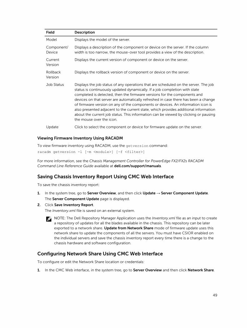
Field Description
Model Displays the model of the server.
Component/Device
Displays a description of the component or device on the server. If the column width is too narrow, the mouse-over tool provides a view of the description.
Current Version
Displays the current version of component or device on the server.
Rollback Version
Displays the rollback version of component or device on the server.
Job Status Displays the job status of any operations that are scheduled on the server. The job status is continuously updated dynamically. If a job completion with state completed is detected, then the firmware versions for the components and devices on that server are automatically refreshed in case there has been a change of firmware version on any of the components or devices. An information icon is also presented adjacent to the current state, which provides additional information about the current job status. This information can be viewed by clicking or pausing the mouse over the icon.
Update Click to select the component or device for firmware update on the server.
Viewing Firmware Inventory Using RACADM
To view firmware inventory using RACADM, use the getversion command:
racadm getversion -l [-m <module>] [-f <filter>]
For more information, see the Chassis Management Controller for PowerEdge FX2/FX2s RACADM Command Line Reference Guide available at dell.com/support/manuals.
Saving Chassis Inventory Report Using CMC Web Interface
To save the chassis inventory report:
1. In the system tree, go to Server Overview, and then click Update → Server Component Update.
The Server Component Update page is displayed.
2. Click Save Inventory Report.
The Inventory.xml file is saved on an external system.
NOTE: The Dell Repository Manager Application uses the Inventory.xml file as an input to create a repository of updates for all the blades available in the chassis. This repository can be later exported to a network share. Update from Network Share mode of firmware update uses this network share to update the components of all the servers. You must have CSIOR enabled on the individual servers and save the chassis inventory report every time there is a change to the chassis hardware and software configuration.
Configuring Network Share Using CMC Web Interface
To configure or edit the Network Share location or credentials:
1. In the CMC Web interface, in the system tree, go to Server Overview and then click Network Share.
49
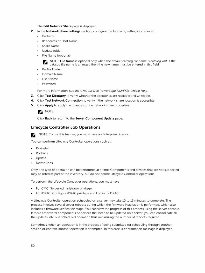
The Edit Network Share page is displayed.
2. In the Network Share Settings section, configure the following settings as required:
• Protocol
• IP Address or Host Name
• Share Name
• Update folder
• File Name (optional)
NOTE: File Name is optional only when the default catalog file name is catalog.xml. If the catalog file name is changed then the new name must be entered in this field.
• Profile Folder
• Domain Name
• User Name
• Password
For more information, see the CMC for Dell PowerEdge FX2/FX2s Online Help.
3. Click Test Directory to verify whether the directories are readable and writeable.
4. Click Test Network Connection to verify if the network share location is accessible.
5. Click Apply to apply the changes to the network share properties.
NOTE:
Click Back to return to the Server Component Update page.
Lifecycle Controller Job Operations
NOTE: To use this feature, you must have an Enterprise License.
You can perform Lifecycle Controller operations such as:
• Re-install
• Rollback
• Update
• Delete Jobs
Only one type of operation can be performed at a time. Components and devices that are not supported may be listed as part of the inventory, but do not permit Lifecycle Controller operations.
To perform the Lifecycle Controller operations, you must have:
• For CMC: Server Administrator privilege.
• For iDRAC: Configure iDRAC privilege and Log in to iDRAC.
A Lifecycle Controller operation scheduled on a server may take 10 to 15 minutes to complete. The process involves several server reboots during which the firmware installation is performed, which also includes a firmware verification stage. You can view the progress of this process using the server console. If there are several components or devices that need to be updated on a server, you can consolidate all the updates into one scheduled operation thus minimizing the number of reboots required.
Sometimes, when an operation is in the process of being submitted for scheduling through another session or context, another operation is attempted. In this case, a confirmation message is displayed
50
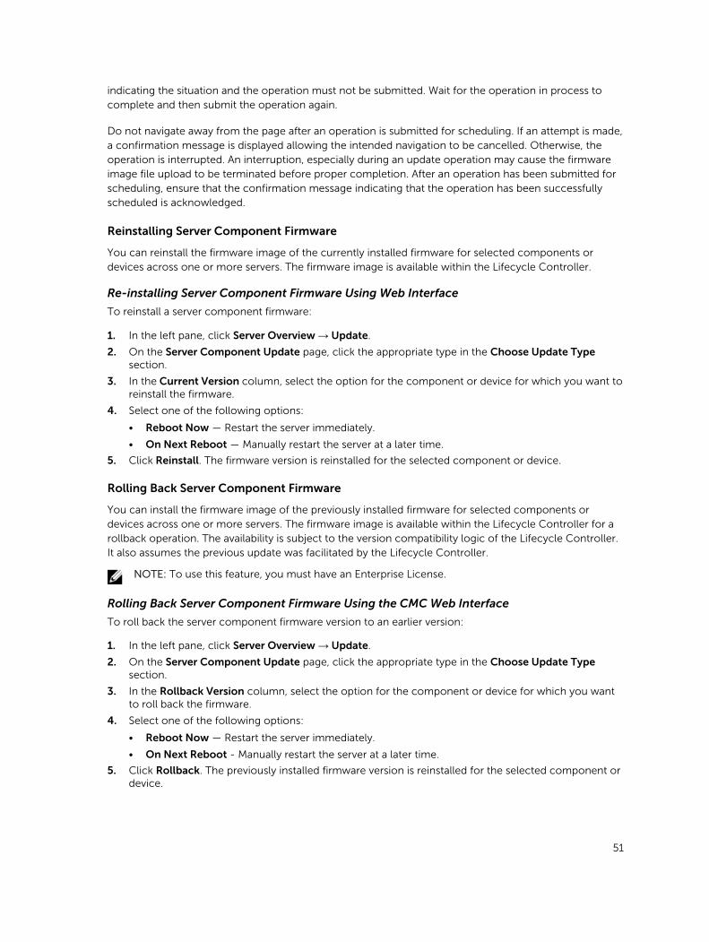
indicating the situation and the operation must not be submitted. Wait for the operation in process to complete and then submit the operation again.
Do not navigate away from the page after an operation is submitted for scheduling. If an attempt is made, a confirmation message is displayed allowing the intended navigation to be cancelled. Otherwise, the operation is interrupted. An interruption, especially during an update operation may cause the firmware image file upload to be terminated before proper completion. After an operation has been submitted for scheduling, ensure that the confirmation message indicating that the operation has been successfully scheduled is acknowledged.
Reinstalling Server Component Firmware
You can reinstall the firmware image of the currently installed firmware for selected components or devices across one or more servers. The firmware image is available within the Lifecycle Controller.
Re-installing Server Component Firmware Using Web Interface
To reinstall a server component firmware:
1. In the left pane, click Server Overview → Update.
2. On the Server Component Update page, click the appropriate type in the Choose Update Type section.
3. In the Current Version column, select the option for the component or device for which you want to reinstall the firmware.
4. Select one of the following options:
• Reboot Now — Restart the server immediately.
• On Next Reboot — Manually restart the server at a later time.
5. Click Reinstall. The firmware version is reinstalled for the selected component or device.
Rolling Back Server Component Firmware
You can install the firmware image of the previously installed firmware for selected components or devices across one or more servers. The firmware image is available within the Lifecycle Controller for a rollback operation. The availability is subject to the version compatibility logic of the Lifecycle Controller. It also assumes the previous update was facilitated by the Lifecycle Controller.
NOTE: To use this feature, you must have an Enterprise License.
Rolling Back Server Component Firmware Using the CMC Web Interface
To roll back the server component firmware version to an earlier version:
1. In the left pane, click Server Overview → Update.
2. On the Server Component Update page, click the appropriate type in the Choose Update Type section.
3. In the Rollback Version column, select the option for the component or device for which you want to roll back the firmware.
4. Select one of the following options:
• Reboot Now — Restart the server immediately.
• On Next Reboot - Manually restart the server at a later time.
5. Click Rollback. The previously installed firmware version is reinstalled for the selected component or device.
51
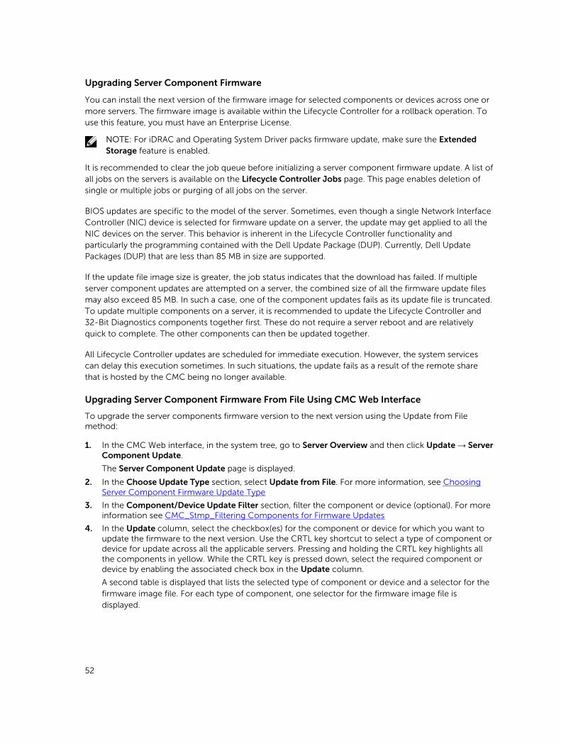
Upgrading Server Component Firmware
You can install the next version of the firmware image for selected components or devices across one or more servers. The firmware image is available within the Lifecycle Controller for a rollback operation. To use this feature, you must have an Enterprise License.
NOTE: For iDRAC and Operating System Driver packs firmware update, make sure the Extended Storage feature is enabled.
It is recommended to clear the job queue before initializing a server component firmware update. A list of all jobs on the servers is available on the Lifecycle Controller Jobs page. This page enables deletion of single or multiple jobs or purging of all jobs on the server.
BIOS updates are specific to the model of the server. Sometimes, even though a single Network Interface Controller (NIC) device is selected for firmware update on a server, the update may get applied to all the NIC devices on the server. This behavior is inherent in the Lifecycle Controller functionality and particularly the programming contained with the Dell Update Package (DUP). Currently, Dell Update Packages (DUP) that are less than 85 MB in size are supported.
If the update file image size is greater, the job status indicates that the download has failed. If multiple server component updates are attempted on a server, the combined size of all the firmware update files may also exceed 85 MB. In such a case, one of the component updates fails as its update file is truncated. To update multiple components on a server, it is recommended to update the Lifecycle Controller and 32-Bit Diagnostics components together first. These do not require a server reboot and are relatively quick to complete. The other components can then be updated together.
All Lifecycle Controller updates are scheduled for immediate execution. However, the system services can delay this execution sometimes. In such situations, the update fails as a result of the remote share that is hosted by the CMC being no longer available.
Upgrading Server Component Firmware From File Using CMC Web Interface
To upgrade the server components firmware version to the next version using the Update from File method:
1. In the CMC Web interface, in the system tree, go to Server Overview and then click Update → Server Component Update.
The Server Component Update page is displayed.
2. In the Choose Update Type section, select Update from File. For more information, see Choosing Server Component Firmware Update Type
3. In the Component/Device Update Filter section, filter the component or device (optional). For more information see CMC_Stmp_Filtering Components for Firmware Updates
4. In the Update column, select the checkbox(es) for the component or device for which you want to update the firmware to the next version. Use the CRTL key shortcut to select a type of component or device for update across all the applicable servers. Pressing and holding the CRTL key highlights all the components in yellow. While the CRTL key is pressed down, select the required component or device by enabling the associated check box in the Update column.
A second table is displayed that lists the selected type of component or device and a selector for the firmware image file. For each type of component, one selector for the firmware image file is displayed.
52
Few devices such as Network Interface Controllers (NICs) and RAID Controllers contain many types and models. The update selection logic automatically filters the relevant device type or model based on the initially selected devices. The primary reason for this automatic filtering behavior is that only one firmware image file for the category can be specified.
NOTE: The update size limitation of either a single DUP or combined DUPs can be ignored if the Extended Storage feature is installed and enabled. For information on enabling extended storage, see Configuring CMC Extended Storage Card
5. Specify the firmware image file for the selected component(s) or devic(es). This is a Microsoft Windows Dell Update Package (DUP) file.
6. Select one of the following options:
• Reboot Now — Reboot immediately. The firmware update is applied immediately
• On Next Reboot — Manually reboot the server at a later time. The firmware update is applied after the next reboot.
NOTE: This step is not valid for Lifecycle Controller and 32-bit Diagnostics firmware update. A server reboot is not required for these devices.
7. Click Update. The firmware version is updated for the selected component or device.
Server Component Single Click Update Using Network Share
The Servers or server component update from a network share using Dell Repository Manager and Dell PowerEdge FX2/FX2s modular chassis integration simplifies the update by using customized bundle firmware, so that you can deploy faster and more easily. Update from a network share provides flexibility to update all the 12G server components at the same time with a single catalog either from a CIFS or from a NFS.
This method provides a quick and easy way to build a custom repository for connected systems that you own using the Dell Repository Manager and the chassis inventory file exported using the CMC Web interface. DRM enables you to create a fully customized repository that only includes the update packages for the specific system configuration. You can also build repositories that contain updates for only out-of-date devices, or a baseline repository that contains updates for all the devices. You can also create update bundles for Linux or Windows based on the update mode required. DRM enables you to save the repository to a CIFS or NFS share. The CMC Web interface enables you to configure the credentials and location details for the share. Using the CMC Web interface, you can then perform the server components update for a single server or multiple servers.
Pre-requisites for Using Network Share Update Mode
The following pre-requisites are required to update server component firmware using Network Share mode:
• The servers must have iDRAC Enterprise license
• Lifecycle controller must be enabled on servers..
• Dell Repository Manager 1.8 or later must be installed on the system.
• You must have CMC Administrator privileges.
53
Upgrading Server Component Firmware From Network Share Using CMC Web Interface
To upgrade the server components firmware version to the next version using the Update from Network Share mode:
1. In the CMC Web interface, in the system tree, go to Server Overview and then click Update → Server Component Update.
The Server Component Update page is displayed.
2. In the Choose Update Type section, select Update from Network Share. For more information, see Choosing Server Component Firmware Update Type.
3. If the Network Share is not connected, configure the Network Share for the chassis. To configure or edit the network share details, in the Network Share Properties table click Edit. For more information see Configuring Network Share Using CMC Web Interface.
4. Click Save Inventory Report to export the chassis inventory file that contains the components and firmware details.
The Inventory.xml file is saved on an external system. The Dell Repository Manager uses the inventory.xml file to create customized bundles of updates. This Repositry is stored in the CIFS or NFS Share configured by CMC. For information on creating a repository using the Dell Repository Manger see the Dell Repository Manager Data Center Version 1.8 User’s Guide and the Dell Repository Manager Business Client Version 1.8 User’s Guide available at dell.com/support/manuals.
5. Click Check for Updates to view the firmware updates available in the network share.
The Component/Device Firmware Inventory section displays the current firmware versions of the components and devices across all the servers present in the chassis and firmware versions of the DUPs available in the Network Share.
NOTE: Click Collapse against a slot to collapse the component and device firmware details for the specific slot. Alternatively, to view all the details again, click Expand.
6. In the Component/Device Firmware Inventory section, select the check box against Select/Deselect All to select all the supported servers. Alternatively, select the check box against the server for which you want to update the server component firmware. You cannot select individual components for the server.
7. Select one of the following options to specify if a system reboot is required after the updates are scheduled:
• Reboot Now — Updates are scheduled and the server is rebooted, immediately applying the updates to the server components.
• On Next Reboot — Updates are scheduled but are applied only after the next server reboot.
8. Click Update to schedule firmware updates for the available components of the selected servers.
A message is displayed based on the type of updates contained and asking you to confirm if you want to continue.
9. Click OK to continue and complete scheduling the firmware update for the selected servers.
NOTE: The Job Status column displays the job status of the operations scheduled on the server. The job status is dynamically updated.
Deleting Scheduled Server Component Firmware Jobs
NOTE: To use this feature, you must have an Enterprise License.
You can delete jobs scheduled for the selected components and/or devices across one or more servers.
54

Deleting Scheduled Server Component Firmware Jobs Using the Web Interface
To delete scheduled server component firmware jobs:
1. In the left pane, click Server Overview, and then click Update.
2. On the Server Component Update page, filter the component or device (optional).
3. In the Job Status column, if a check box is displayed next to the job status, it implies that a Lifecycle Controller job is in progress and currently in the indicated state. It can be selected for a job-deletion operation.
4. Click Delete Job. The jobs are deleted for the selected components or devices.
Recovering iDRAC Firmware Using CMC
iDRAC firmware is typically updated using iDRAC interfaces such as the iDRAC web interface, the SM-CLP command line interface, or operating system specific update packages downloaded from support.dell.com. For more information, see the Dell Integrated Dell Remote Access Controller (iDRAC) User’s Guide .
55
5Viewing Chassis Information and Monitoring Chassis and Component HealthYou can view information and monitor the health of the following:
• CMC
• All severs and individual servers
• IO Modules
• Fans
• Power Supply Units (PSUs)
• Temperature sensors
• PCIe devices
Viewing Chassis and Component Summaries
When you log in to the CMC web interface, the Chassis Health page displays the health of the chassis and its components. It displays a graphical view of the chassis and its components. It is dynamically updated, and the component sub-graphic overlays and text hints are automatically changed to reflect the current state.
To view the chassis health, click Chassis Overview. The system displays the overall health status of the chassis, CMC, server modules, IO Modules (IOM), fans, power supply units (PSUs), and PCIe devices. Detailed information about each component is displayed when you click that component. In addition, the latest events in the CMC Hardware Log are also displayed. For more information, see the Dell Integrated Dell Remote Access Controller (iDRAC) User’s Guide .
If your chassis is configured as a Group Lead, the Group Health page is displayed after login. It displays the chassis level information and alerts. All active, critical, and non-critical alerts are displayed.
Chassis Graphics
The chassis is represented by the front, back, and the top views (the upper and lower images respectively). Servers, and KVMs are shown in the front view and the remaining components are shown in the back view. Component selection is indicated by a blue cast and is controlled by clicking the image of the required component. When a component is present in the chassis, an icon of the component type is displayed in the graphics in the position (slot), where the component has been installed. Empty positions are shown with a charcoal gray background. The component icon visually indicates the state of the
56
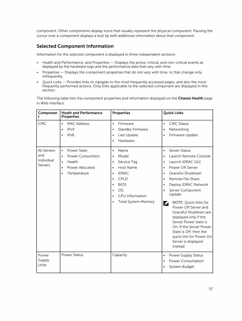
component. Other components display icons that visually represent the physical component. Pausing the cursor over a component displays a tool tip with additional information about that component.
Selected Component Information
Information for the selected component is displayed in three independent sections:
• Health and Performance, and Properties — Displays the active, critical, and non-critical events as displayed by the hardware logs and the performance data that vary with time.
• Properties — Displays the component properties that do not vary with time, or that change only infrequently.
• Quick Links — Provides links to navigate to the most frequently accessed pages, and also the most frequently performed actions. Only links applicable to the selected component are displayed in this section.
The following table lists the component properties and information displayed on the Chassis Health page in Web interface.
Component
Heath and Performance Properties
Properties Quick Links
CMC • MAC Address
• IPv4
• IPv6
• Firmware
• Standby Firmware
• Last Update
• Hardware
• CMC Status
• Networking
• Firmware Update
All Servers and Individual Servers
• Power State
• Power Consumtion
• Health
• Power Allocated
• Temperature
• Name
• Model
• Service Tag
• Host Name
• iDRAC
• CPLD
• BIOS
• OS
• CPU Information
• Total System Memory
• Server Status
• Launch Remote Console
• Launch iDRAC GUI
• Power Off Server
• Graceful Shutdown
• Remote File Share
• Deploy iDRAC Network
• Server Component Update
NOTE: Quick links for Power Off Server and Graceful Shutdown are displayed only if the Server Power state is On. If the Server Power State is Off, then the quick link for Power On Server is displayed instead.
Power Supply Units
Power Status Capacity • Power Supply Status
• Power Consumption
• System Budget
57
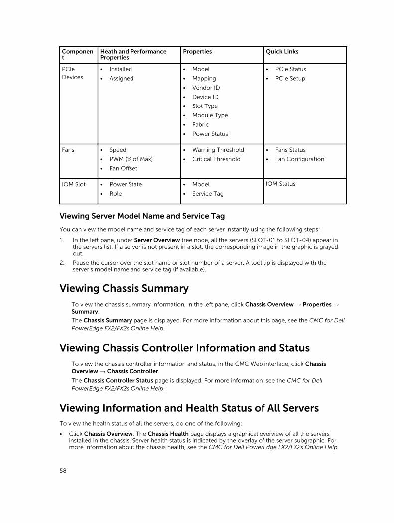
Component
Heath and Performance Properties
Properties Quick Links
PCIe Devices
• Installed
• Assigned
• Model
• Mapping
• Vendor ID
• Device ID
• Slot Type
• Module Type
• Fabric
• Power Status
• PCIe Status
• PCIe Setup
Fans • Speed
• PWM (% of Max)
• Fan Offset
• Warning Threshold
• Critical Threshold
• Fans Status
• Fan Configuration
IOM Slot • Power State
• Role
• Model
• Service Tag
IOM Status
Viewing Server Model Name and Service Tag
You can view the model name and service tag of each server instantly using the following steps:
1. In the left pane, under Server Overview tree node, all the servers (SLOT-01 to SLOT-04) appear in the servers list. If a server is not present in a slot, the corresponding image in the graphic is grayed out.
2. Pause the cursor over the slot name or slot number of a server. A tool tip is displayed with the server’s model name and service tag (if available).
Viewing Chassis SummaryTo view the chassis summary information, in the left pane, click Chassis Overview → Properties → Summary.
The Chassis Summary page is displayed. For more information about this page, see the CMC for Dell PowerEdge FX2/FX2s Online Help.
Viewing Chassis Controller Information and StatusTo view the chassis controller information and status, in the CMC Web interface, click Chassis Overview → Chassis Controller.
The Chassis Controller Status page is displayed. For more information, see the CMC for Dell PowerEdge FX2/FX2s Online Help.
Viewing Information and Health Status of All ServersTo view the health status of all the servers, do one of the following:
• Click Chassis Overview. The Chassis Health page displays a graphical overview of all the servers installed in the chassis. Server health status is indicated by the overlay of the server subgraphic. For more information about the chassis health, see the CMC for Dell PowerEdge FX2/FX2s Online Help.
58
• Click Chassis Overview → Server Overview. The Servers Status page provides an overview of the servers in the chassis. For more information, see the Online Help.
Viewing Information and Health Status of the IOMsTo view health status of the IOMs, in the CMC Web interface, do any of the following:
1. Click Chassis Overview .
The Chassis Health page is displayed. The graphics in the left pane displays the rear, front, and top view of the chassis and contains the health status for the IOM. IOM health status is indicated by the overlay of the IOM sub-graphic. Move the cursor over the individual IOM sub-graphic. The text hint provides additional information about that IOM. Click the IOM sub-graphic to view the IOM information in the right pane.
2. Go to Chassis Overview → I/O Module Overview .
The I/O Module Status page provides an overview of IOM associated with the chassis. For more information, see the CMC for Dell PowerEdge FX2/FX2s Online Help.
Viewing Information and Health Status of FansCMC controls the speed of the chassis fan by increasing or decreasing the fan speed on the basis of system events. You can run the fan in three modes such as Low, Medium, and High (fan offset). For more information about configuring a fan, see the CMC for Dell PowerEdge FX2/FX2s Online Help.
To set up the properties of fans by using RACADM commands, type the following command at the CLI interface.
racadm fanoffset [-s <off|low|medium|high>]NOTE: The CMC monitors the temperature sensors in the chassis and automatically adjust the fan speed as needed. When overridden using this command, the CMC will always run the fan to the selected speed even though the chassis does not require the fans to run at that speed. However, you can override to maintain a minimum fan speed by the racadm fanoffset command.
For more information about the RACADM commands, see the Chassis Management Controller for PowerEdge FX2/FX2s RACADM Command Line Reference Guide available at dell.com/support/manuals.
CMC generates an alert and increases the fan speeds when the following events occur:
• CMC ambient temperature threshold is exceeded.
• A fan stops functioning.
• A fan is removed from the chassis.
NOTE: During updates of CMC or iDRAC firmware on a server, some or all of the fan units in the chassis rotates at 100%. This is normal.
To view the health status of fans, in the CMC Web interface, do any of the following:
1. Go to Chassis Overview.
The Chassis Health page is displayed. The upper right section of chassis graphics provides the top left view of the chassis and contains the health status of the fans. Fan health status is indicated by the overlay of the fan sub-graphic. Move the cursor over the fan sub-graphic. The text hint provides additional information about a fan. Click the fan sub-graphic to view the fan information in the right pane.
2. Go to Chassis Overview → Fans.
59
The Fans Status page provides the status, speed measurements in revolutions per minute (RPMs), and threshold values of the fans in the chassis. There can be one or more fans.
NOTE: In the event of a communication failure between CMC and the fan unit, CMC cannot obtain or display the health status for the fan unit.
NOTE: The following message is displayed when both the fans are not present in the slots or if a fan is rotating at a low speed:
Fan <number> is less than the lower critical threshold.For more information, see the Online Help.
Configuring Fans
Fan Offset — This feature allows you to increase the airflow delivery to the PCIe card slots. An example usage of the Fan Offset is when you use high-power or custom PCIe cards that require more cooling than normal. The Fan Offset feature has options of Off, Low, Medium, and High. These settings correspond to a fan speed offset (increase) of 20%, 50%, and 100% of the maximum speed respectively. There are also minimum speeds setup for each option, which are 35% for Low, 65% for Medium, and 100% for High.
Using the Medium Fan Offset setting for example, increases the speed of fans by 50% of its maximum speed. The increase is above the speed already set by the system for cooling on the basis of installed hardware configuration.
With any of the Fan Offset options enabled, the power consumption will be increased. The system will be louder with the Low offset, noticeably louder with the Medium offset, and significantly louder with the High offset. When the Fan Offset option is not enabled, the fan speeds will be reduced to the default speeds required for system cooling for the installed hardware configuration.
To set the offset feature, go to Chassis Overview → Fans → Setup. On the Advanced Fan Configuration page, from the Value drop-down menu corresponding to Fan Offset, select appropriately.
For more information about the Fan Offset feature, see the Online Help.
For setting up these features by using RACADM commands, user the following command:
racadm fanoffset [-s <off|low|medium|high>]
Viewing Front Panel PropertiesTo view the front panel properties:
1. In the left pane, click Chassis Overview → Front Panel.
2. On the Properties page, you can view the following:• Power Button Properties• KVM Properties• Front Panel Indicators
Viewing KVM Information and Health StatusTo view the health status of the KVMs associated with the chassis, do any of the following:
Click Chassis Overview → Front Panel.
60

On the Status page, under the KVM Properties section, you can view the status and properties of a KVM associated with the chassis. For more information, see the Online Help.
Viewing Information and Health Status of Temperature SensorsTo view the health status of the temperature sensors:
In the left pane, click Chassis Overview → Temperature Sensors.
The Temperature Sensors Status page displays the status and readings of the temperature probes on the entire chassis (chassis and servers). For more information, see Online Help.
NOTE: The temperature probes value cannot be edited. Any change beyond the threshold generates an alert that causes the fan speed to vary. For example, if the CMC ambient temperature probe exceeds the threshold, the speed of the fans on the chassis increases.
61
6Configuring CMCChassis Management Controller enables you to configure properties, set up users, and alerts to perform remote management tasks.
Before you begin configuring the CMC, you must first configure the CMC network settings to allow CMC to be managed remotely. This initial configuration assigns the TCP/IP networking parameters that enable access to the CMC.
You can configure CMC using Web interface or Setting up Initial Access to CMC RACADM.
NOTE: When you configure CMC for the first time, you must be logged in as root user to execute RACADM commands on a remote system. Another user can be created with privileges to configure CMC.
After setting up the CMC and performing the basic configurations, you can do the following:
• Modify the network settings, if required.
• Configure interfaces to access CMC.
• Setup chassis groups, if required.
• Configure servers, I/O module, or front panel.
• Configure VLAN settings.
• Obtain the required certificates.
• Add and configure CMC users with privileges.
• Configure and enable e-mail alerts and SNMP traps.
• Set the power cap policy, if required.
NOTE: The following characters cannot be used in the property strings of both the CMC interfaces (GUI and CLI):
• &#
• < and > together
• ; (semicolon)
Enabling or Disabling DHCP for the CMC Network Interface Address
When enabled, the CMC’s DHCP for NIC address feature requests and obtains an IP address from the Dynamic Host Configuration Protocol (DHCP) server automatically. This feature is disabled by default.
You can enable the DHCP to obtain an IP address from the DHCP server automatically.
62
Enabling the CMC Network InterfaceTo enable or disable the CMC network interface for both IPv4 and IPv6, type:
racadm config -g cfgLanNetworking -o cfgNicEnable 1racadm config -g cfgLanNetworking -o cfgNicEnable 0
NOTE:
If you disable CMC network interface, the disable operation performs the following actions:
• Disables the network interface access to out-of-band chassis management, including iDRAC and IOM management.
• Prevents the down link status detection.
To disable only CMC network access, disable both CMC IPv4 and CMC IPv6.
NOTE: The CMC NIC is enabled by default.
To enable or disable the CMC IPv4 addressing, type:
racadm config -g cfgLanNetworking -o cfgNicIPv4Enable 1 racadm config -g cfgLanNetworking -o cfgNicIPv4Enable 0
NOTE: The CMC IPv4 addressing is enabled by default.
To enable or disable the CMC IPv6 addressing, type:
racadm config -g cfgIpv6LanNetworking -o cfgIPv6Enable 1 racadm config -g cfgIpv6LanNetworking -o cfgIPv6Enable 0
NOTE: The CMC IPv6 addressing is disabled by default.
For an IPv4 network, to disable DHCP and specify static CMC IP address, gateway, and subnet mask, type:
racadm config -g cfgLanNetworking -o cfgNicUseDHCP 0racadm config -g cfgLanNetworking -o cfgNicIpAddress <static IP address>racadm config -g cfgLanNetworking -o cfgNicGateway <static gateway>racadm config -g cfgLanNetworking -o cfgNicNetmask <static subnet mask>
By default, the DHCP is disabled. To enable DHCP and use the DHCP server on the network to assign iDRAC or CMC IPv4 address, subnet mask, and gateway, type:
racadm config -g cfgLanNetworking -o cfgNicUseDHCP 1By default, for IPv6, the CMC requests and automatically obtains a CMC IP address from the IPv6 autoconfiguration mechanism.
For an IPv6 network, to disable the Autoconfiguration feature and specify a static CMC IPv6 address, gateway, and prefix length, type:
racadm config -g cfgIPv6LanNetworking -ocfgIPv6AutoConfig 0racadm config -g cfgIPv6LanNetworking -ocfgIPv6Address <IPv6 address>racadm config -g cfgIPv6LanNetworking -ocfgIPv6PrefixLength 64racadm config -g cfgIPv6LanNetworking -ocfgIPv6Gateway <IPv6 address>
63
Enabling or Disabling DHCP for DNS IP AddressesBy default, the CMC’s DHCP for DNS address feature is disabled. When enabled, this feature obtains the primary and secondary DNS server addresses from the DHCP server. While using this feature, you do not have to configure static DNS server IP addresses.
To enable the DHCP for DNS address feature and specify the static preferred and alternate DNS server addresses, type:
racadm config -g cfgLanNetworking -ocfgDNSServersFromDHCP 1
To enable the DHCP for DNS address feature for IPv6 and specify the static preferred and alternate DNS server addresses, type:
racadm config -g cfgIPv6LanNetworking -ocfgIPv6DNSServersFromDHCP6 1
Setting Static DNS IP addressesNOTE: The static DNS IP addresses settings are not valid unless the DCHP for DNS address feature is disabled.
For IPv4, to set the preferred primary and secondary DNS IP server addresses, type:
racadm config -g cfgLanNetworking -o cfgDNSServer1 <IP-address>racadm config -g cfgLanNetworking -o cfgDNSServer2 <IPv4-address>
For IPv6, to set the preferred and secondary DNS IP Server addresses, type:
racadm config -g cfgIPv6LanNetworking -ocfgIPv6DNSServer1 <IPv6-address>racadm config -g cfgIPv6LanNetworking -ocfgIPv6DNSServer2 <IPv6-address>
Viewing and Modifying CMC Network LAN Settings
The LAN settings, such as community string and SMTP server IP address, affect both the CMC and the external settings of the chassis.
When IPv6 is enabled at boot time, three router solicitations are sent after every four seconds. If external network switches are running the Spanning Tree Protocol (STP), the external switch ports may be blocked for more than 12 seconds in which the IPv6 router solicitations are sent. In such cases, there may be a period when IPv6 connectivity is limited, until router advertisements are gratuitously sent by the IPv6 routers.
NOTE: Changing the CMC network settings may disconnect your current network connection.
NOTE: You must have Chassis Configuration Administrator privilege to set up CMC network settings.
64
Viewing and Modifying CMC Network LAN Settings Using CMC Web Interface
To view and modify the CMC LAN network settings using CMC Web interface:
1. In the left pane, click Chassis Overview, and then click Network. The Network Configuration page displays the current network settings.
2. Modify the general, IPv4, or IPv6 settings as required. For more information, see the Online Help.
3. Click Apply Changes for each section to apply the settings.
Viewing and Modifying CMC Network LAN Settings Using RACADM
To view IPv4 settings, use the object cfgCurrentLanNetworking with the following subcommands:
• getniccfg• getconfig
To view IPv6 settings, use the cfgIpv6LanNetworking with the getconfig subcommand.
To view IPv4 and IPv6 addressing information for the chassis, use the getsysinfo subcommand.
For more information about the subcommands and objects, see the Chassis Management Controller for PowerEdge FX2/FX2s RACADM Command Line Reference Guide.
Configuring DNS Settings (IPv4 and IPv6)• CMC Registration — To register the CMC on the DNS server, type:
racadm config -g cfgLanNetworking -ocfgDNSRegisterRac 1
NOTE: Some DNS servers only register names of 31 characters or fewer. Make sure the designated name is within the DNS required limit.
NOTE: The following settings are valid only if you have registered the CMC on the DNS server by setting cfgDNSRegisterRac to 1.
• CMC Name — By default, the CMC name on the DNS server is cmc-<service tag>. To change the CMC name on the DNS server, type:
racadm config -g cfgLanNetworking -o cfgDNSRacName <name>where < name > is a string of up to 63 alphanumeric characters and hyphens. For example: cmc-1,
d-345.
NOTE: If a DNS Domain name is not specified then the maximum number of characters is 63. If a domain name is specified then the number of characters in CMC name plus the number of characters in the DNS Domain Name must be less than or equal to 63 characters.
• DNS Domain Name — The default DNS domain name is a single blank character. To set a DNS domain name, type:
racadm config -g cfgLanNetworking -ocfgDNSDomainName <name>where < name > is a string of up to 254 alphanumeric characters and hyphens. For example: p45, a-
tz-1, r-id-001.
65
Configuring Auto Negotiation, Duplex Mode, and Network Speed (IPv4 and IPv6)When enabled, the auto negotiation feature determines whether the CMC automatically sets the duplex mode and network speed by communicating with the nearest router or switch. By default, auto negotiation feature is enabled.
You can disable auto negotiation and specify the duplex mode and network speed by typing:
racadm config -g cfgNetTuning -o cfgNetTuningNicAutoneg 0racadm config -g cfgNetTuning -o cfgNetTuningNicFullDuplex <duplex mode>
where:
< duplex mode > is 0 (half duplex) or 1 (full duplex, default)
racadm config -g cfgNetTuning -o cfgNetTuningNicSpeed <speed>where:
< speed > is 10 or 100 (default).
Configuring Management Port 2
The second network port on the CMC can be used for daisy-chaining CMCs together for cable reduction, or as a redundant port for failover networking operation. Management Port 2 may be connected to the top-of-rack (TOR) switch or to another switch. There is no requirement that the two CMC NIC ports be connected to the same subnet.
The CMC cannot be cabled for Management Network Port redundancy prior to actually configuring it for this operation. The CMC must use the standard single network connection for deployment, after which the second redundant connection may be made.
NOTE: When Management Port 2 is set for Redundant but is cabled for Stacking, the downstream CMCs (further from the TOR switch) will not have a network link.
NOTE: When Management Port 2 is set for Stacking but is cabled for Redundant (two connections to the TOR switch), routing loops could cause a network storm.
To specify Redundant operation, use racadm config –g cfgNetTuning –o cfgNetTuningNicRedundant 1 command.
To specify Stacking operation, use racadm config –g cfgNetTuning –o cfgNetTuningNicRedundant 0 command.
By default, the Management Port 2 is set for Stacking.
Configuring Management Port 2 Using CMC Web Interface
To configure Management Port using CMC Web Interface:1. In the left pane, click Chassis Overview → Network, and then click the Network tab.
2. On the Network Configuration page, in the General Settings section, next to Management Port 2, select either Redundant or Stacking.
66
3. Click Apply Changes.
• When Management Port 2 is set for Redundant but is cabled for Stacking, the downstream CMCs (further from the top-of-rack switch) does not have a network link.
• When Management Port 2 is set for Stacking but is cabled for Redundant (two connections to the TOR switch), routing loops could cause a network storm.
Configuring Management Port 2 Using RACADM
To specify Redundant operation, use racadm config –g cfgNetTuning –o cfgNetTuningNicRedundant 1 command.
To specify Stacking operation, use racadm config –g cfgNetTuning –o cfgNetTuningNicRedundant 0 command.
By default, the Management Port 2 is set for Stacking.
Configuring Services
You can configure and enable the following services on CMC:
• CMC serial console — Enable access to CMC using the serial console.
• Web Server — Enable access to CMC web interface. Disabling the web server also disables Remote RACADM.
• SSH — Enable access to CMC through firmware RACADM.
• Telnet — Enable access to CMC through firmware RACADM
• Remote RACADM — Enable access to CMC using RACADM.
• SNMP — Enable CMC to send SNMP traps for events.
• Remote Syslog — Enable CMC to log events to a remote server. To use this feature, you must have an Enterprise license.
NOTE: When modifying CMC service port numbers for SSH, Telnet, HTTP, or HTTPS, avoid using commonly used ports by OS services such as port 111. See Internet Assigned Numbers Authority (IANA) reserved ports at http://www.iana.org/assignments/service-names-port-numbers/service-names-port-numbers.xhtml.
CMC includes a web server that is configured to use the industry-standard SSL security protocol to accept and transfer encrypted data from and to clients over the Internet. The web server includes a Dell self-signed SSL Digital Certificate (Server ID), and is responsible for accepting and responding to secure HTTP requests from clients. This service is required by the web interface and remote RACADM CLI tool for communicating with CMC.
If the web server resets, wait at least one minute for the services to become available again. A web server reset usually happens as a result of any of the following events:
• Network configuration or network security properties are changed through the CMC web user interface or RACADM.
• Web server port configuration is changed through the web user interface or RACADM.
• CMC is reset.
• A new SSL server certificate is uploaded.
67
NOTE: To modify service settings, you must have the Chassis Configuration Administrator privilege.
Remote syslog is an additional log target for CMC. After you configure the remote syslog, each new log entry generated by CMC is forwarded to the respective destinations.
NOTE: Because the network transport for the forwarded log entries is UDP, there is no guaranteed delivery of log entries, nor is there any feedback to CMC about whether the log entries were received successfully.
Configuring Services Using RACADM
To enable and configure the various services, use the following RACADM objects:
• cfgRacTuning • cfgRacTuneRemoteRacadmEnable
For more information about these objects, see the Chassis Management Controller for PowerEdge FX2/FX2s RACADM Command Line Reference Guide available at dell.com/support/manuals.
If the firmware on the server does not support a feature, configuring a property related to that feature displays an error. For example, using RACADM to enable remote syslog on an unsupported iDRAC displays an error message.
Similarly, when displaying the iDRAC properties using the RACADM getconfig command, the property
values are displayed as N/A for an unsupported feature on the server.
For example:
$ racadm getconfig -g cfgSessionManagement -m server-1# cfgSsnMgtWebServerMaxSessions=N/A# cfgSsnMgtWebServerActiveSessions=N/A# cfgSsnMgtWebServerTimeout=N/A# cfgSsnMgtSSHMaxSessions=N/A# cfgSsnMgtSSHActiveSessions=N/A# cfgSsnMgtSSHTimeout=N/A# cfgSsnMgtTelnetMaxSessions=N/A# cfgSsnMgtTelnetActiveSessions=N/A# cfgSsnMgtTelnetTimeout=N/A
Configuring CMC Extended Storage CardYou can enable or repair the optional Removable Flash Media for use as an extended non-volatile storage. Some CMC features depend on extended nonvolatile storage for their operation.
To enable or repair the Removable Flash Media using the CMC web interface:
1. In the left pane, go to Chassis Overview, and then click Chassis Controller → Flash Media.
2. On the Removable Flash Media page, from the drop-down menu, select one of the following as appropriate:
• Repair active controller media
• Stop using flash media for storing chassis data
For more information about these options, see the CMC for Dell PowerEdge FX2/FX2s Online Help.
3. Click Apply to apply the selected option.
68
Setting Up Chassis GroupCMC enables you to monitor multiple chassis from a single lead chassis. When a chassis group is enabled, CMC in the lead chassis generates a graphical display of the status of the lead chassis and all member chassis within the chassis group. To use this feature, you must have an Enterprise License.
The Chassis group features are:
• Displays images portraying the front and back of each chassis, a set for the leader and a set for each member.
• Health concerns for the leader and members of a group are recognized by red or yellow overlays and an X or an ! on the component with the symptoms. Details are visible below the chassis image when you click the chassis image or Details.
• Quick launch links are available to open web pages for member chassis or servers.
• A server and Input/Output inventory is available for a group.
• A selectable option is available to synchronize a new member’s properties to the leader’s properties when the new member is added to the group.
A chassis group may contain a maximum of 19 members. Also, a leader or member can only participate in one group. You cannot join a chassis, either as a leader or member, that is part of a group to another group. You can delete the chassis from a group and add it later to a different group.
To set up the Chassis Group using the CMC web interface:
1. Log in with chassis administrator privileges to the leader chassis.
2. Click Setup → Group Administration.
3. On the Chassis Group page, under Role, select Leader. A field to add the group name is displayed.
4. Type the group name in the Group Name field, and then click Apply.
NOTE: The same rules that apply for a domain name apply to the group name.
When the chassis group is created, the GUI automatically switches to the Chassis Group page. The left pane indicates the group by the group name and the lead chassis, and the unpopulated member chassis appear in the left pane.
NOTE: When the chassis group is created, the Chassis Overview item in the tree structure is replaced with the name of the lead chassis.
Adding Members To Chassis Group
After the Chassis Group is setup, add members to the group by doing the following:
1. Log in with chassis administrator privileges to the leader chassis.
2. Select the lead chassis in the tree.
3. Click Setup → Group Administration.
4. Under Group Management, enter the member’s IP address or DNS name in the Hostname/IP Address field.
NOTE: For MCM to function properly, you must use the default HTTPS port (443) on all group members and the leader chassis.
5. In the User Name field, enter a user name with chassis administrator privileges for the member chassis.
69

6. Type the corresponding password in the Password field.
7. Optionally, select Sync New Member with Leader Properties to push leader properties to the member. For more information about adding members to chassis group, see Synchronizing a New Member With Leader Chassis Propertie.
8. Click Apply.
9. To add a maximum of eight members, complete the tasks in step 4 through step 8. The chassis names of the new members appear in the Members dialog box.
NOTE: The credentials entered for a member are passed securely to the member chassis to establish a trust relationship between the member and lead chassis. The credentials are not persisted on either chassis, and are never exchanged again after the initial trust relationship is established.
Removing a Member from the Leader
You can remove a member from the group from the lead chassis. To remove a member:
1. Log in with chassis administrator privileges to the leader chassis.
2. In the left pane, select the lead chassis.
3. Click Setup → Group Administration.
4. From the Remove Members list, select the member’s name to be deleted, and then click Apply.
The lead chassis then communicates to the member or members, if more than one is selected, that it has been removed from the group. The member name is removed. The member chassis may not receive the message, if a network issue prevents contact between the leader and the member. In this case, disable the member from the member chassis to complete the removal.
Disbanding a Chassis Group
To disband a chassis group from the lead chassis:
1. Log in with administrator privileges to the leader chassis.
2. Select the lead chassis in the left pane.
3. Click Setup → Group Administration.
4. In the Chassis Group page, under Role, select None, and then click Apply.
The lead chassis then communicates to all the members that they have been removed from the group. The lead chassis can be assigned as a leader or member of a new group.
If a network issue prevents contact between the leader and the member, the member chassis may not receive the message. In this case, disable the member from the member chassis to complete the removal process.
Disabling an Individual Member at the Member Chassis
Sometimes a member cannot be removed from a group by the lead chassis. This can happen if network connectivity to the member is lost. To remove a member from a group at the member chassis:
1. Log in with chassis administrator privileges to the member chassis.
2. In the left pane, click Chassis Overview → Setup → Group Administration.
3. Select None, and then click Apply.
70

Launching the Web page of a Member Chassis or Server
You can access the web page of the member chassis, remote console of the server, or the web page of the iDRAC server from the lead chassis group page. If the member device has the same login credentials as the lead chassis, you can use the same credentials to access the member device.
NOTE: Single Sign On and Smart Card Login are not supported in Multiple Chassis Management. Launching members by Single Sign On from Lead chassis requires a common username/password between Lead and members. Use of common username/password works only with Active Directory, local, and LDAP users.
To navigate to member devices:
1. Log in to the lead chassis.
2. Select Group: name in the tree.
3. If a member CMC is the required destination, select Launch CMC for the required chassis.
If a server in a chassis is the required destination:
a. Select the image of the destination chassis.
b. In the chassis image that appears in the Health section, select the server.
c. In the box labeled Quick Links, select the destination device. A new window is displayed with the destination page or login screen.
Propagating Leader Chassis Properties to Member Chassis
You can apply the properties from the leader to the member chassis of a group. To synchronize a member with the leader properties:
1. Login with administrator privileges to the leader chassis.
2. Select the Lead chassis in the tree.
3. Click Setup → Group Administration.
4. In the Chassis Properties Propagation section, select one of the propagation types:
• On-Change Propagation — Select this option for automatic propagation of the selected chassis property settings. The property changes are propagated to all current group members, whenever lead properties are changed.
• Manual Propagation — Select this option for manual propagation of the chassis group leader properties with its members. The lead chassis property settings are propagated to group members only when a lead chassis administrator clicks Propagate.
5. In the Propagation Properties section, select the categories of lead configuration properties to be propagated to member chassis.
Select only those setting categories that you want identically configured, across all members of the chassis group. For example, select Logging and Alerting Properties category, to enable all chassis in the group to share the logging and alerting configuration settings of the lead chassis.
6. Click Save.
If On-Change Propagation is selected, the member chassis take on the properties of the leader. If Manual Propagation is selected, click Propagate whenever you want to propagate the chosen settings to member chassis. For more information on propagation of leader chassis properties to member chassis, see the Online Help.
71
Synchronizing a New Member With Leader Chassis Properties
You can apply the properties from the leader to a newly added member chassis of a group. To synchronize a new member with the leader properties:
1. Log in with administrator privileges to the leader chassis.
2. Select the lead chassis in the tree structure.
3. Click Setup → Group Administration.
4. While adding a new member to the group, in the Chassis Group page, select Sync New Member with Leader Properties.
5. Click Apply. The member takes on the properties of the leader.
The following configuration service properties of several systems within the chassis are affected after synchronization:Table 4. Configuration Service Properties
Property Navigation
SNMP configuration In the left pane, click Chassis Overview → Network → Services → SNMP.
Chassis remote logging In the left pane, click Chassis Overview → Network → Services → Remote Syslog.
User authentication using LDAP and Active Directory services
In the left pane, click Chassis Overview → User Authentication → Directory Services.
Chassis alerts In the left pane, click Chassis Overview, and then click Alerts.
Server Inventory for MCM group
A group is a lead chassis that has 0 to 19 chassis group members. The Chassis Group Health page displays all the member chassis and allows you to save the server inventory report to a file, using standard browser download capability. The report contains data for:
• All servers currently in all the group chassis (including the leader).
• Empty slots and extension slots.
Saving Server Inventory Report
To save the server inventory report using the CMC web interface:
1. In the left pane, select the Group.
2. On the Chassis Group Health page, click Save Inventory Report. The File Download dialog box is displayed asking you to open or save the file.
3. Click Save and specify the path and file name for the server module inventory report.
NOTE: The chassis group leader and chassis group member chassis, and the server module in the associated chassis, must be turned on to get the most accurate server module inventory report.
72
Configuring Multiple CMCs Using RACADMUsing RACADM, you can configure one or more CMCs with identical properties.
When you query a specific CMC card using its group ID and object ID, RACADM creates the racadm.cfg configuration file from the retrieved information. By exporting the file to one or more CMCs, you can configure your controllers with identical properties in a minimal amount of time.
NOTE: Some configuration files contain unique CMC information (such as the static IP address) that must be modified before you export the file to other CMCs.
1. Use RACADM to query the target CMC that contains the desired configuration.
NOTE: The generated configuration file is myfile.cfg. You can rename the file. The .cfg file does not contain user passwords. When the .cfg file is uploaded to the new CMC, you must re-add all passwords.
2. Open a Telnet/SSH text console to the CMC, log in, and type:
racadm getconfig -f myfile.cfgNOTE: Redirecting the CMC configuration to a file using getconfig -f is only supported with
the remote RACADM interface.
3. Modify the configuration file using a plain-text editor (optional). Any special formatting characters in the configuration file may corrupt the RACADM database.
4. Use the newly created configuration file to modify a target CMC. At the command prompt, type:
racadm config -f myfile.cfg5. Reset the target CMC that was configured. At the command prompt, type:
racadm resetThe getconfig -f myfile.cfg subcommand requests the CMC configuration for the CMC and
generates the myfile.cfg file. If required, you can rename the file or save it to a different location.
You can run the getconfig command to perform the following actions:
• Display all configuration properties in a group (specified by group name and index).
• Display all configuration properties for a user by user name.
The config subcommand loads the information into other CMCs. The Server Administrator uses the
config command to synchronize the user and password database.
Parsing Rules
• Lines that start with a hash character (#) are treated as comments.
A comment line must start in column one. A "#" character in any other column is treated as a # character.
Some modem parameters may include # characters in their strings. An escape character is not required. You may want to generate a .cfg from a racadm getconfig -f <filename> .cfg command, and then perform a racadm config -f <filename> .cfg command to a different
CMC, without adding escape characters.
73

For example:
## This is a comment[cfgUserAdmin]cfgUserAdminPageModemInitString= <Modem init # nota comment>
• All group entries must be surrounded by open- and close-brackets ([ and ]).
The starting [ character that denotes a group name must be in column one. This group name must be specified before any of the objects in that group. Objects that do not include an associated group name generate an error. The configuration data is organized into groups as defined in the database property chapter of the RACADM Command Line Reference Guide for iDRAC and CMC. The following example displays a group name, object, and the object’s property value:
[cfgLanNetworking] -{group name}cfgNicIpAddress=143.154.133.121 {object name}{object value}
• All parameters are specified as "object=value" pairs with no white space between the object, =, or value. White spaces that are included after the value are ignored. A white space inside a value string remains unmodified. Any character to the right of the = (for example, a second =, a #, [, ], and so on) is taken as-is. These characters are valid modem chat script characters.
[cfgLanNetworking] -{group name}cfgNicIpAddress=143.154.133.121 {object value}
• The .cfg parser ignores an index object entry.
You cannot specify which index is used. If the index already exists, it is either used or the new entry is created in the first available index for that group.
The racadm getconfig -f <filename>.cfg command places a comment in front of index
objects, allowing you to see the included comments.
NOTE: You may create an indexed group manually using the following command:
racadm config -g <groupname> -o <anchored object> -i <index 1-16> <unique anchor name>
• The line for an indexed group cannot be deleted from a .cfg file. If you do delete the line with a text editor, RACADM stops when it parses the configuration file and alert you of the error.
You must remove an indexed object manually using the following command:
racadm config -g <groupname> -o <objectname> -i <index 1-16> ""NOTE: A NULL string (identified by two " characters) directs the CMC to delete the index for the specified group.
To view the contents of an indexed group, run the following command:
racadm getconfig -g <groupname> -i <index 1-16>• For indexed groups the object anchor must be the first object after the [ ] pair. The following are
examples of the current indexed groups:
[cfgUserAdmin]cfgUserAdminUserName= <USER_NAME>
• When using remote RACADM to capture the configuration groups into a file, if a key property within a group is not set, the configuration group is not saved as part of the configuration file. If these configuration groups are needed to be cloned onto other CMCs, the key property must be set before executing the getconfig -f command. Alternatively, you can manually enter the missing properties into the configuration file after running the getconfig -f command. This is true for all the RACADM–indexed groups.
74

This is the list of the indexed groups that exhibit this behavior and their corresponding key properties:
– cfgUserAdmin — cfgUserAdminUserName
– cfgEmailAlert — cfgEmailAlertAddress
– cfgTraps — cfgTrapsAlertDestIPAddr
– cfgStandardSchema — cfgSSADRoleGroupName
– cfgServerInfo — cfgServerBmcMacAddress
Modifying the CMC IP Address
When you modify the CMC IP address in the configuration file, remove all unnecessary <variable> = <value> entries. Only the actual variable group’s label with [ and ] remains, including the two <variable> = <value> entries pertaining to the IP address change.
Example:
## Object Group "cfgLanNetworking"#[cfgLanNetworking]cfgNicIpAddress=10.35.10.110cfgNicGateway=10.35.10.1
This file is updated as follows:
## Object Group "cfgLanNetworking"#[cfgLanNetworking]cfgNicIpAddress=10.35.9.143# comment, the rest of this line is ignoredcfgNicGateway=10.35.9.1
The command racadm config -f <myfile>.cfg parses the file and identifies any errors by line
number. A correct file updates the proper entries. Additionally, you can use the same getconfig command from the previous example to confirm the update.
Use this file to download company-wide changes or to configure new systems over the network with the command, racadm getconfig -f <myfile>.cfg.
NOTE: Anchor is a reserved word and should not be used in the .cfg file.
75
7Configuring ServersYou can configure the following settings of a server:
• Slot Names
• iDRAC Network Settings
• DRAC VLAN Tag Settings
• First Boot Device
• Server FlexAddress
• Remote File Share
• BIOS Settings Using Server Clone
Configuring Slot NamesSlot names are used to identify individual servers. When choosing slot names, the following rules apply:
• Names may contain a maximum of 15 non-extended ASCII characters (ASCII codes 32 through 126). Also standard, and special characters are allowed in the names.
• Slot names must be unique within the chassis. Slots should not have the same name.
• Strings are not case-sensitive. Server-1, server-1, and SERVER-1 are equivalent names.
• Slot names must not begin with the following strings:
– Switch-
– Fan-
– PS-
– DRAC-
– MC-
– Chassis
– Housing-Left
– Housing-Right
– Housing-Center
• The strings Server-1 through Server-4 may be used, but only for the corresponding slot. For example, Server-3 is a valid name for slot 3, but not for slot 4. However, Server-03 is a valid name for any slot.
NOTE: To change a slot name, you must have the Chassis Configuration Administrator privilege.
The slot name setting in the web interface resides on CMC only. If a server is removed from the chassis, the slot name setting does not remain with the server.
76
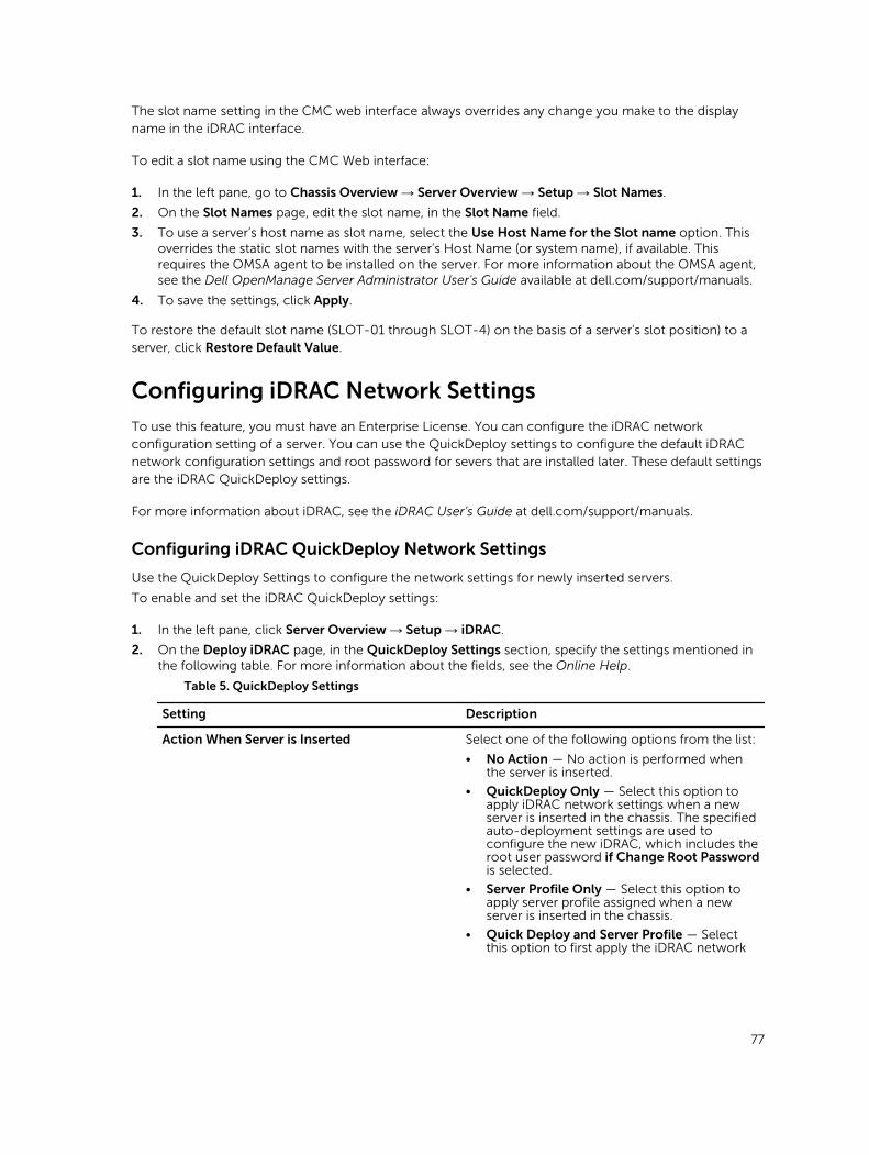
The slot name setting in the CMC web interface always overrides any change you make to the display name in the iDRAC interface.
To edit a slot name using the CMC Web interface:
1. In the left pane, go to Chassis Overview → Server Overview → Setup → Slot Names.
2. On the Slot Names page, edit the slot name, in the Slot Name field.
3. To use a server’s host name as slot name, select the Use Host Name for the Slot name option. This overrides the static slot names with the server’s Host Name (or system name), if available. This requires the OMSA agent to be installed on the server. For more information about the OMSA agent, see the Dell OpenManage Server Administrator User's Guide available at dell.com/support/manuals.
4. To save the settings, click Apply.
To restore the default slot name (SLOT-01 through SLOT-4) on the basis of a server's slot position) to a server, click Restore Default Value.
Configuring iDRAC Network Settings
To use this feature, you must have an Enterprise License. You can configure the iDRAC network configuration setting of a server. You can use the QuickDeploy settings to configure the default iDRAC network configuration settings and root password for severs that are installed later. These default settings are the iDRAC QuickDeploy settings.
For more information about iDRAC, see the iDRAC User’s Guide at dell.com/support/manuals.
Configuring iDRAC QuickDeploy Network Settings
Use the QuickDeploy Settings to configure the network settings for newly inserted servers.
To enable and set the iDRAC QuickDeploy settings:
1. In the left pane, click Server Overview → Setup → iDRAC.
2. On the Deploy iDRAC page, in the QuickDeploy Settings section, specify the settings mentioned in the following table. For more information about the fields, see the Online Help.
Table 5. QuickDeploy Settings
Setting Description
Action When Server is Inserted Select one of the following options from the list:
• No Action — No action is performed when the server is inserted.
• QuickDeploy Only — Select this option to apply iDRAC network settings when a new server is inserted in the chassis. The specified auto-deployment settings are used to configure the new iDRAC, which includes the root user password if Change Root Password is selected.
• Server Profile Only — Select this option to apply server profile assigned when a new server is inserted in the chassis.
• Quick Deploy and Server Profile — Select this option to first apply the iDRAC network
77
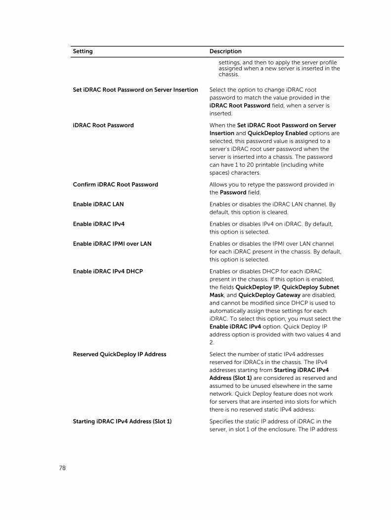
Setting Description
settings, and then to apply the server profile assigned when a new server is inserted in the chassis.
Set iDRAC Root Password on Server Insertion Select the option to change iDRAC root password to match the value provided in the iDRAC Root Password field, when a server is inserted.
iDRAC Root Password When the Set iDRAC Root Password on Server Insertion and QuickDeploy Enabled options are selected, this password value is assigned to a server's iDRAC root user password when the server is inserted into a chassis. The password can have 1 to 20 printable (including white spaces) characters.
Confirm iDRAC Root Password Allows you to retype the password provided in the Password field.
Enable iDRAC LAN Enables or disables the iDRAC LAN channel. By default, this option is cleared.
Enable iDRAC IPv4 Enables or disables IPv4 on iDRAC. By default, this option is selected.
Enable iDRAC IPMI over LAN Enables or disables the IPMI over LAN channel for each iDRAC present in the chassis. By default, this option is selected.
Enable iDRAC IPv4 DHCP Enables or disables DHCP for each iDRAC present in the chassis. If this option is enabled, the fields QuickDeploy IP, QuickDeploy Subnet Mask, and QuickDeploy Gateway are disabled, and cannot be modified since DHCP is used to automatically assign these settings for each iDRAC. To select this option, you must select the Enable iDRAC IPv4 option. Quick Deploy IP address option is provided with two values 4 and 2.
Reserved QuickDeploy IP Address Select the number of static IPv4 addresses reserved for iDRACs in the chassis. The IPv4 addresses starting from Starting iDRAC IPv4 Address (Slot 1) are considered as reserved and assumed to be unused elsewhere in the same network. Quick Deploy feature does not work for servers that are inserted into slots for which there is no reserved static IPv4 address.
Starting iDRAC IPv4 Address (Slot 1) Specifies the static IP address of iDRAC in the server, in slot 1 of the enclosure. The IP address
78
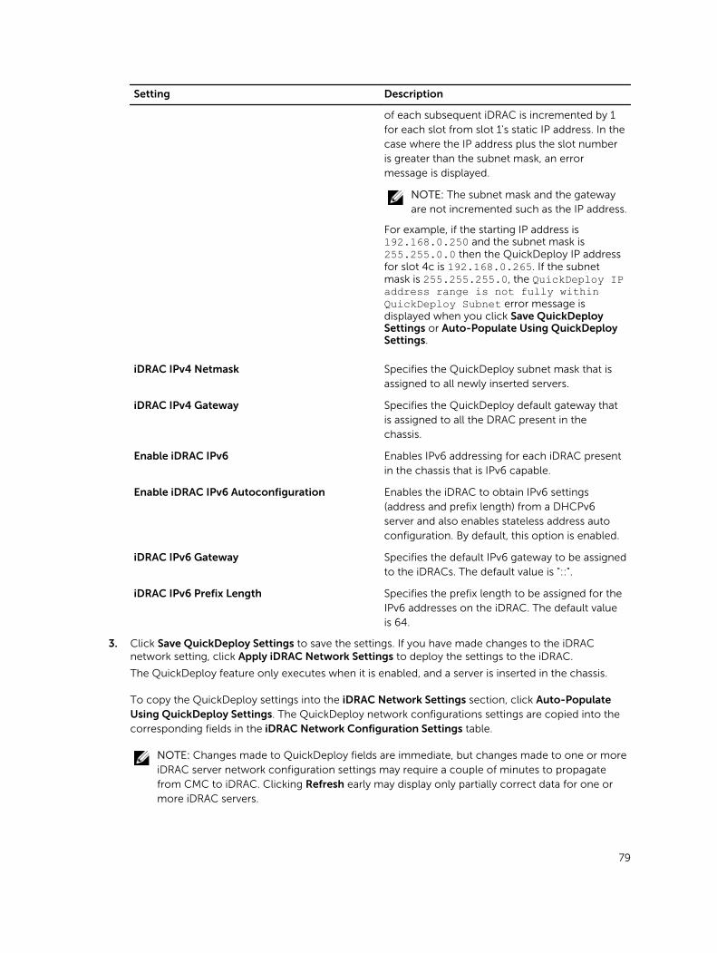
Setting Description
of each subsequent iDRAC is incremented by 1 for each slot from slot 1's static IP address. In the case where the IP address plus the slot number is greater than the subnet mask, an error message is displayed.
NOTE: The subnet mask and the gateway are not incremented such as the IP address.
For example, if the starting IP address is 192.168.0.250 and the subnet mask is 255.255.0.0 then the QuickDeploy IP address for slot 4c is 192.168.0.265. If the subnet mask is 255.255.255.0, the QuickDeploy IP address range is not fully within QuickDeploy Subnet error message is displayed when you click Save QuickDeploy Settings or Auto-Populate Using QuickDeploy Settings.
iDRAC IPv4 Netmask Specifies the QuickDeploy subnet mask that is assigned to all newly inserted servers.
iDRAC IPv4 Gateway Specifies the QuickDeploy default gateway that is assigned to all the DRAC present in the chassis.
Enable iDRAC IPv6 Enables IPv6 addressing for each iDRAC present in the chassis that is IPv6 capable.
Enable iDRAC IPv6 Autoconfiguration Enables the iDRAC to obtain IPv6 settings (address and prefix length) from a DHCPv6 server and also enables stateless address auto configuration. By default, this option is enabled.
iDRAC IPv6 Gateway Specifies the default IPv6 gateway to be assigned to the iDRACs. The default value is "::".
iDRAC IPv6 Prefix Length Specifies the prefix length to be assigned for the IPv6 addresses on the iDRAC. The default value is 64.
3. Click Save QuickDeploy Settings to save the settings. If you have made changes to the iDRAC network setting, click Apply iDRAC Network Settings to deploy the settings to the iDRAC.
The QuickDeploy feature only executes when it is enabled, and a server is inserted in the chassis.
To copy the QuickDeploy settings into the iDRAC Network Settings section, click Auto-Populate Using QuickDeploy Settings. The QuickDeploy network configurations settings are copied into the corresponding fields in the iDRAC Network Configuration Settings table.
NOTE: Changes made to QuickDeploy fields are immediate, but changes made to one or more iDRAC server network configuration settings may require a couple of minutes to propagate from CMC to iDRAC. Clicking Refresh early may display only partially correct data for one or more iDRAC servers.
79
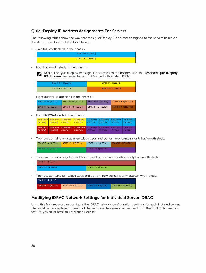
QuickDeploy IP Address Assignments For Servers
The following tables show the way that the QuickDeploy IP addresses assigned to the servers based on the sleds present in the FX2/FX2s Chassis:
• Two full-width sleds in the chassis:
• Four half-width sleds in the chassis:
NOTE: For QuickDeploy to assign IP addresses to the bottom sled, the Reserved QuickDeploy IPAddresses field must be set to 4 for the bottom sled iDRAC.
• Eight quarter-width sleds in the chassis:
• Four FM120x4 sleds in the chassis:
• Top row contains only quarter-width sleds and bottom row contains only half-width sleds:
• Top row contains only full-width sleds and bottom row contains only half-width sleds:
• Top row contains full-width sleds and bottom row contains only quarter-width sleds:
Modifying iDRAC Network Settings for Individual Server iDRAC
Using this feature, you can configure the iDRAC network configurations settings for each installed server. The initial values displayed for each of the fields are the current values read from the iDRAC. To use this feature, you must have an Enterprise License.
80

To modify the iDRAC Network Settings:
1. In the left pane, click Server Overview, and then click Setup. On the Deploy iDRAC page the iDRAC Network Settings section lists the iDRAC IPv4 and IPv6 network configuration settings of all the installed servers.
2. Modify the iDRAC network settings as required for the servers.
NOTE: You must select the Enable LAN option to specify the IPv4 or IPv6 settings. For information about the fields, see the CMC for Dell PowerEdge FX2/FX2s Online Help.
3. To deploy the setting to iDRAC, click Apply iDRAC Network Settings. Any changes made to the QuickDeploy Settings are also saved.
The iDRAC Network Settings table reflects future network configuration settings; the values shown for installed servers may or may not be the same as the currently installed iDRAC network configuration settings. Click Refresh to update the iDRAC Deploy page with each installed iDRAC network configuration settings after changes are made.
NOTE: Changes made to QuickDeploy fields are immediate, but changes made to one or more iDRAC server network configuration settings may require a couple of minutes to propagate from CMC to iDRAC. Clicking Refresh too soon may display only partially correct data for a one or more iDRAC servers.
Modifying iDRAC Network Settings Using RACADM
RACADM config or getconfig commands support the -m <module> option for the following
configuration groups:
• cfgLanNetworking • cfgIPv6LanNetworking• cfgRacTuning• cfgRemoteHosts• cfgSerial• cfgSessionManagement
For more information about the property default values and ranges, see the Dell Integrated Dell Remote Access Controller (iDRAC) RACADM Command Line Reference Guide and Chassis Management Controller for PowerEdge FX2/FX2s RACADM Command Line Reference Guide available at dell.com/support/manuals.
Configuring iDRAC VLAN Tag Settings
VLANs are used to allow multiple virtual LANs to co-exist on the same physical network cable and to segregate the network traffic for security or load management purposes. When you enable the VLAN functionality, each network packet is assigned a VLAN tag. VLAN tags are chassis properties. They remain with the chassis even when a component is removed.
Configuring iDRAC VLAN Tag Settings Using Web Interface
To configure VLAN for server:
1. Go to any of the following pages:
• In the left pane, click Chassis Overview → Network → VLAN.
81
• In the left pane, click Chassis Overview → Server Overview and click Setup → VLAN.
2. On the VLAN Tag Settings page, in the iDRAC section, enable VLAN for the servers, set the priority and enter the ID. For more information about the fields, see the CMC for Dell PowerEdge FX2/FX2s Online Help.
3. Click Apply to save the settings.
Configuring iDRAC VLAN Tag Settings Using RACADM
• Specify the VLAN ID and priority of a particular server with the following command:
racadm setniccfg -m server-<n> -v <VLAN id> <VLAN priority>The valid values for <n> are 1–4.
The valid values for <VLAN> are 1–4000 and 4021–4094. Default is 1.
The valid values for <VLAN priority> are 0–7. Default is 0.
For example:
racadm setniccfg -m server-1 -v 1 7
For example:
• To remove a server VLAN, disable the VLAN capabilities of the specified server's network:
racadm setniccfg -m server-<n> -vThe valid values for <n> are 1–16.
For example:
racadm setniccfg -m server-1 -v
Setting First Boot Device
You can specify the CMC first boot device for each server. This may not be the actual first boot device for the server, or may not even represent a device present in that server. It represents a device sent by CMC to the server and used as its first boot device of that server. This device can be set as the default first-boot device or an one-time device so that you can boot an image to perform tasks such as running diagnostics or reinstalling an operating system.
You can set the first boot device for the next boot only or for all subsequent reboots. You can also set the first boot device for the server. The system boots from the selected device on the next and subsequent reboots and remains as the first boot device in the BIOS boot order, until it is changed again either from the CMC web interface or from the BIOS boot sequence.
NOTE: The first boot device setting in CMC web Interface overrides the system BIOS boot settings.
The boot device that you specify must exist and contain a bootable media.
You can set the following devices for first boot. However, to set a device as a default first-boot device, select Default.
To not to override the server firmware version if the firmware version running on the server is same as the version available in the first boot device, select None.
82
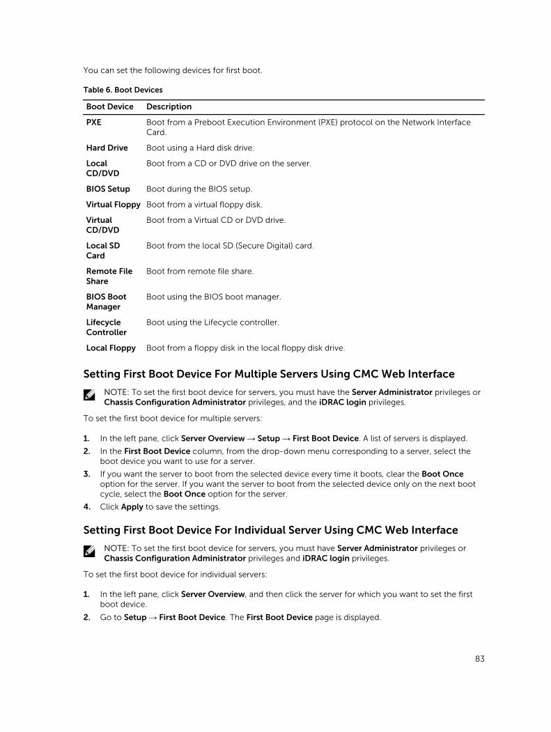
You can set the following devices for first boot.
Table 6. Boot Devices
Boot Device Description
PXE Boot from a Preboot Execution Environment (PXE) protocol on the Network Interface Card.
Hard Drive Boot using a Hard disk drive.
Local CD/DVD
Boot from a CD or DVD drive on the server.
BIOS Setup Boot during the BIOS setup.
Virtual Floppy Boot from a virtual floppy disk.
Virtual CD/DVD
Boot from a Virtual CD or DVD drive.
Local SD Card
Boot from the local SD (Secure Digital) card.
Remote File Share
Boot from remote file share.
BIOS Boot Manager
Boot using the BIOS boot manager.
Lifecycle Controller
Boot using the Lifecycle controller.
Local Floppy Boot from a floppy disk in the local floppy disk drive.
Setting First Boot Device For Multiple Servers Using CMC Web Interface
NOTE: To set the first boot device for servers, you must have the Server Administrator privileges or Chassis Configuration Administrator privileges, and the iDRAC login privileges.
To set the first boot device for multiple servers:
1. In the left pane, click Server Overview → Setup → First Boot Device. A list of servers is displayed.
2. In the First Boot Device column, from the drop-down menu corresponding to a server, select the boot device you want to use for a server.
3. If you want the server to boot from the selected device every time it boots, clear the Boot Once option for the server. If you want the server to boot from the selected device only on the next boot cycle, select the Boot Once option for the server.
4. Click Apply to save the settings.
Setting First Boot Device For Individual Server Using CMC Web Interface
NOTE: To set the first boot device for servers, you must have Server Administrator privileges or Chassis Configuration Administrator privileges and iDRAC login privileges.
To set the first boot device for individual servers:
1. In the left pane, click Server Overview, and then click the server for which you want to set the first boot device.
2. Go to Setup → First Boot Device. The First Boot Device page is displayed.
83
3. From the First Boot Device drop-down menu, select the boot device you want to use for each server.
4. If you want the server to boot from the selected device every time it boots, clear the Boot Once option for the server. If you want the server to boot from the selected device only on the next boot cycle, select the Boot Once option for the server
5. Click Apply to save the settings.
Setting First Boot Device Using RACADM
To set the first boot device, use the cfgServerFirstBootDevice object.
To enable boot once for a device, use the cfgServerBootOnce object.
For more information about these objects, see the Chassis Management Controller for PowerEdge FX2s RACADM Command Line Reference Guide available at dell.com/support/manuals.
Configuring Sled Network Uplink
You can configure the Sled Network Uplink only on the PowerEdge FM120x4 sleds that contain an internal network switch.
To configure the Sled Network Uplink, go to Chassis Overview → Server Overview → Setup → Sled Network Uplink
Select one of the following values for Sled network uplink configuration Property:
• Standard (aggregated): Uplink configuration where all four IOM uplink ports are configured in a single trunk group and all LOMs are mapped to that group. This is selected by default.
• Network adapter isolation (enhanced security): Uplink configuration similar to standard, but routing between local nodes is not allowed.
• Isolated networks: Uplink configuration where each node’s LOM1 is mapped to IOM A1 and LOM2 is mapped to IOM A2.
Deploying Remote File Share
The Remote Virtual Media File Share feature maps a file from a share drive on the network to one or more servers through CMC to deploy or update an operating system. When connected, the remote file is accessible similar to a file that you can access on a local server. Two types of media are supported: floppy drives and CD/DVD drives.
To perform a remote file share operation (connect, disconnect, or deploy), you must have the Chassis Configuration Administrator or Server Administrator privileges. To use this feature, you must have an Enterprise license.
To configure the remote file share:
1. In the left pane, click Server Overview → Setup → Remote File Share.
2. On the Deploy Remote File Share page, type appropriate data in the fields. For more information about the field descriptions, see the CMC for Dell PowerEdge FX2/FX2s Online Help.
3. To connect to a remote file share, click Connect. To connect a remote file share, you must provide the path, user name, and password. A successful operation allows access to the media.
84
Click Disconnect to disconnect a previously-connected remote file share.
Click Deploy to deploy the media device.
NOTE: Before you click the Deploy button, make sure that you save all the working files, because this action restarts the server.
When you click Deploy, the following tasks are executed:
• The remote file share is connected.
• The file is selected as the first boot device for the servers.
• The server is restarted.
• Power is supplied to the server if the server is turned off.
Configuring Server FlexAddress
For information about configuring FlexAddress for servers, see Configuring FlexAddress for Chassis-Level Fabric and Slots Using CMC Web Interface. To use this feature, you must have an Enterprise License.
Configuring Profile Settings Using Server Configuration Replication
The server configurations replicating feature allows you to apply all profile settings from a specified server to one or more servers. Profile settings that can be replicated are those profile settings which can be modified and are intended to be replicated across servers. The following three profile groups for servers are displayed and can be replicated:
• BIOS — This group includes only the BIOS settings of a server.
• BIOS and Boot — This group includes the BIOS and the Boot settings of a server.
• All Settings — This version includes all the settings of the server and components on that server. These profiles are generated from:
– 12th generation servers with iDRAC7 1.57.57 or later and Lifecycle Controller 2 version 1.1 or later
– 13th generation servers with iDRAC8 2.05.05 with Lifecycle Controller 2.00.00.00 or later.
The server cloning feature supports iDRAC7 and iDRAC8 Servers. Earlier generation RAC servers are listed, but are greyed out on the main page, and are not enabled to use this feature.
To use the server configurations replication feature:
• iDRAC must have the minimum version that is required. iDRAC7 servers require version 1.57.57. iDRAC8 servers require version 2.05.05.
• Server must be turned on.
You can:
• View profile settings on a server or from a saved profile.
• Save a profile from a server.
• Apply a profile to other servers.
• Import stored profiles from a management station or remote file share.
• Edit the profile name and description.
85
• Export stored profiles to a management station or remote file share.
• Delete stored profiles.
• Deploy selected profiles to the target devices using Quick Deploy option.
• Display the log activity for recent server profile tasks.
Accessing Profile Page
You can add, manage, and apply profiles to one or more servers using the Profile page.
To access the Profile page using the CMC Web interface, in the left pane, click Chassis Overview → Server Overview → Setup → Profiles. The Profiles page is displayed.
Managing Stored Profiles
You can edit, view, or delete BIOS profiles. To manage the stored profiles of a CMC:
1. In the left pane, click Chassis Overview → Server Overview → Setup → Profiles.
2. On the Profiles page, in the Apply Profile section, click Manage Profiles. The Manage BIOS Profiles page is displayed.
• To edit a profile, click Edit.
• To view BIOS settings, click View.
• To delete a profile, click Delete. For more information about the field descriptions, see the CMC for Dell PowerEdge FX2/FX2s Online Help.
Adding or Saving Profile
Before copying the properties of a server, first capture the properties to a stored profile. Create a stored profile and provide a name and optional description for each profile. You can save a maximum of 16 stored profiles on the CMC nonvolatile extended storage media.
NOTE: If a remote share is available, you can store a maximum of 100 profiles using the CMC extended storage and remote share. For more information, see Configuring Network Share Using CMC web Interface
Removing or disabling the non-volatile extended storage media prevents access to Stored Profiles, and disables the Server Cloning feature.
To add a profile:
1. Go to the Server Profiles page. In the Server Profiles section, click Apply and Save Profiles.
2. Select the server from whose settings you want to generate the profile, and then click Save Profile. The Save Profile section is displayed.
3. Select Extended Storage or Network Share as the location to save the profile.
NOTE: The Network Share option is enabled and the details are displayed in the Stored Profiles section only if the network share is mounted and is accessible. If the Network Share is not connected, configure the Network Share for the chassis. To configure the Network Share, click Edit in the Stored Profiles section. For more information, see Configuring Network Share Using CMC web Interface
4. In the Profile Name and Description fields, enter the profile name and description (optional), and click Save Profile.
86
NOTE:
When saving a Server Profile the list of characters that are not supported for the Profile Name include the character hash (#), comma (,) and question mark (?).
The standard ASCII extended character set is supported. The following special characters are not supported:
), “, ., *, >, <, \, /, :, and |
CMC communicates with the LC to get the available server profile settings and store them as a named profile.
A progress indicator indicates that the Save operation is in progress. After the action is complete, a message, "Operation Successful" is displayed.
NOTE: The process to gather the settings runs in the background. Hence, it may take some time before the new profile is displayed. If the new profile is not displayed, check the profile log for errors.
Applying Profile
Server cloning is possible only when server profiles are available as stored profiles in the nonvolatile media on the CMC or stored on the remote share. To initiate a server cloning operation, you can apply a stored profile to one or more servers.
The operation status, slot number, slot name, and model name is displayed for each server in the Apply Profile table.
NOTE: If a server does not support Lifecycle Controller or the chassis is turned off, you cannot apply a profile to the server.
To apply a profile to one or more servers:
1. Go to the Server Profiles page. In the Save and Apply Profiles section, select the server or servers for which you want to apply the selected profile.
The Select Profile drop-down menu gets enabled.
NOTE: The Select Profile drop-down menu displays all available profiles and sorted by type, including those that are on the repository and SD card.
2. From the Select Profile drop-down menu, select the profile that you want to apply.
The Apply Profile option gets enabled.
3. Click Apply Profile.
A warning message is displayed that applying a new server profile overwrites the current settings and also reboots the selected servers. You are prompted to confirm if you want to continue the operation.
NOTE: To perform server cloning operations on servers, the CSIOR option must be enabled for the servers. If CSIOR option is disabled, a warning message is displayed that CSIOR is not enabled for the servers. To complete the blade cloning operation, make sure to enable CSIOR option on the servers.
4. Click OK to apply the profile to the selected server.
The selected profile is applied to the servers and the servers may be rebooted immediately, if necessary. For more information, see the CMC for Dell PowerEdge FX2/FX2s Online Help.
87
Importing Profile
You can import a server profile that is stored on a management station to CMC.
To import a stored profile from CMC:
1. In the Server Profiles page, in the Stored Profiles section, click Import Profile.
The Import Server Profile section is displayed.
2. Click Browse to access the profile from the required location and then click Import Profile.
For more information, see the Online Help.
Exporting Profile
You can export a stored server profile to a specified path on a management station.
To export a stored profile:
1. Go to the Server Profiles page. In the Stored Profiles section, select the required profile, and then click Export Copy of Profile.
A File Download message is displayed prompting you to open or save the file.
2. Click Save or Open to export the profile to the required location.
NOTE: If the source profile is on the SD card, then a warning message is displayed that if the profile is exported, then the description is lost. Press OK to continue exporting the profile.
A message is displayed prompting you to select the destination of the file:
• Local or Network Share if the source file is on a SD card.
NOTE: The Network Share option is enabled and the details are displayed in the Stored Profiles section only if the network share is mounted and is accessible. If the Network Share is not connected, configure the Network Share for the chassis. To configure the Network Share, click Edit in the Stored Profiles section. For more information see Configuring Network Share Using CMC web Interface
• Local or SD Card if the source file is on the Network Share.
For more information, see the Online Help.
3. Select Local, Extended Storage, or Network Share as the destination location based on the options displayed.
• If you select Local, a dialog box appears allowing you to save the profile to a local directory.
• If you select Extended Storage or Network Share, a Save Profile dialog box is displayed.
4. Click Save Profile to save the profile to the selected location.
Editing Profile
You can edit the name and description of a server profile that is stored on the CMC nonvolatile media (SD Card).
To edit a stored profile:
1. Go to the Server Profiles page. In the Stored Profiles section, select the required profile and then click Edit Profile.
The Edit BIOS Profile — <Profile Name> section is displayed.
2. Edit the profile name and description of the server profile as required and then click Edit Profile.
88
NOTE: You can edit the profile description only for profiles stored on SD cards.
For more information, see the Online Help.
Viewing Profile Settings
To view Profile settings for a selected server, go to the Server Profiles page. In the Server Profiles section, click View in the Server Profile column for the required server. The View Settings page is displayed.
For more information on the displayed settings, see the Online Help.
NOTE: The CMC Server Configuration Replication feature retrieves and displays the settings for a specific server, only if the Collect System Inventory on Restart (CSIOR) option is enabled.
To enable CSIOR, after rebooting the server, from the F2 setup, select iDRAC Settings → Lifecycle Controller, enable CSIOR and save the changes.
To enable CSIOR on:
1. 12th generation servers — After rebooting the server, from the F2 setup, select iDRAC Settings → Lifecycle Controller, enable CSIOR and save the changes.
2. 13th generation servers —After rebooting the server, when prompted, press F10 to access Lifecycle Controller. Go to the Hardware Inventory page by selecting Hardware Configuration → Hardware Inventory. On the Hardware Inventory page, click Collect System Inventory on Restart.
Viewing Stored Profile Settings
To view profile settings of the stored server profiles, go to the Server Profiles page. In the Server Profiles section, click View in the View Profile column for the required server. The View Settings page is displayed. For more information on the displayed settings, see the CMC for Dell PowerEdge FX2/FX2s Online Help.
Viewing Profile Log
To view the profile log, in the Server Profiles page, see the Recent Profile Log section. This section lists the 10 latest profile log entries directly from server cloning operations. Each log entry displays the severity, the time and date of submission of the server configuration replication operation, and the replication log message description. The log entries are also available in the RAC log. To view the other available entries, click Go to Profile Log. The Profile Log page is displayed. For more information, see the Online Help.
Completion Status And Troubleshooting
To check the completion status of an applied BIOS profile:
1. In the left pane, click Chassis Overview → Server Overview → Setup → Profiles.
2. On the Server Profiles page, note down the Job ID (JID) of the submitted job from the Recent Profile Log section.
3. In the left pane, click Server Overview → Troubleshooting → Lifecycle Controller Jobs. Search for the same JID in the Jobs table. For more information about performing Lifecycle Controller jobs using CMC, see Lifecycle Controller Job Operations.
89
Quick Deploy of Profiles
The Quick Deploy feature enables you to assign a stored profile to a server slot. Any server supporting server configuration replication that is inserted into a slot is configured using the profile assigned to that slot. You can perform the Quick Deploy action only if the Action When Server is Inserted option in the Deploy iDRAC page is set to Server Profile or Quick Deploy and Server Profile. Selecting this option allows to apply the server profile assigned when a new server is inserted in the chassis. To go to the
Deploy iDRAC page, select Server Overview → Setup → iDRAC . Profiles that can be deployed are contained in the SD card.
NOTE: To set up the profiles for quick deploy, you must have Chassis Administrator privileges.
Assigning Server Profiles to Slots
The Server Profiles page enables you to assign server profiles to slots. To assign a profile to the chassis slots:
1. In the Server Profiles page, click Profiles for QuickDeploy section.
The current profile assignments are displayed for the slots in the select boxes contained in the Assign Profile column.
NOTE: You can perform the Quick Deploy action only if the Action When Server is Inserted option in the Deploy iDRAC page is set to Server Profile or Quick Deploy then Server Profile. Selecting this option allows to apply the server profile assigned when a new server is inserted in the chassis.
2. From the drop-down menu, select the profile to assign to the required slot. You can select profiles to apply to multiple slots.
3. Click Assign Profile.
The profiles gets applied to the selected slots.
NOTE: When the FM120x4 sled is inserted, the stored profile assigned to the server slot is applied to all the four servers.
NOTE:
• A slot that does not have any profile assigned to it is indicated by the term "No Profile Selected" that appears in the select box.
• To remove a profile assignment from one or more slots, select the slots and click Remove Assignment. A message is displayed warning you that removing a profile from the slot or slots removes the XML configuration settings in the profile from any servers inserted in the slots when Quick Deploy Profiles feature is enabled. Click OK to remove the profile assignments.
• To remove all profile assignments from a slot, in the drop-down menu, select No Profile Selected.
NOTE: When a profile is deployed to a server using the Quick Deploy Profile feature, the progress and results of the application are retained in the Profile Log.
90
NOTE:
The Network Share option is enabled and the details are displayed in the Stored Profiles section only if the network share is mounted and is accessible. If the Network Share is not connected, configure the Network Share for the chassis. To configure the Network Share, click Edit in the Stored Profiles section. For more information see Configuring Network Share Using CMC Web Interface
Launching iDRAC using Single Sign-On
CMC provides limited management of individual chassis components, such as servers. For complete management of these individual components, CMC provides a launch point for the server’s management controller (iDRAC) web-based interface.
A user may be able to launch iDRAC web interface without having to login a second time, as this feature utilizes single sign-on. Single sign-on policies are:
• A CMC user who has server administrative privilege, is automatically logged into iDRAC using single sign-on. Once on the iDRAC site, this user is automatically granted Administrator privileges. This is true even if the same user does not have an account on iDRAC, or if the account does not have the Administrator’s privileges.
• A CMC user who does NOT have the server administrative privilege, but has the same account on iDRAC is automatically logged into iDRAC using single sign-on. Once on the iDRAC site, this user is granted the privileges that were created for the iDRAC account.
• A CMC user who does not have the server administrative privilege, or the same account on the iDRAC, does NOT automatically logged into iDRAC using single sign-on. This user is directed to the iDRAC login page when the Launch iDRAC GUI is clicked.
NOTE: The term "the same account" in this context means that the user has the same login name with a matching password for CMC and for iDRAC. The user who has the same login name without a matching password, is considered to have the same account.
NOTE: Users may be prompted to log in to iDRAC (see the third Single Sign-on policy bullet above).
NOTE: If the iDRAC network LAN is disabled (LAN Enabled = No), single sign-on is not available.
If the server is removed from the chassis, the iDRAC IP address is changed, or the iDRAC network connection experiences a problem, then clicking Launch iDRAC GUI may display an error page.
Launching iDRAC from Server Status Page
To launch the iDRAC management console for an individual server:
1. In the left pane, expand Server Overview. All four servers appear in the expanded Servers Overview list.
2. Click the server for which you want to launch the iDRAC Web interface.
3. On the Servers Status page, click Launch iDRAC GUI.
The iDRAC Web interface is displayed. For information about the field descriptions, see the CMC for Dell PowerEdge FX2/FX2s Online Help.
91
Launching iDRAC from Servers Status Page
To launch the iDRAC management console from the Servers Status page:
1. In the left pane, click Server Overview.
2. On the Servers Status page, click Launch iDRAC for the server you want to launch the iDRAC Web interface.
Launching Remote Console from Server Status PageTo launch a remote console for an individual server:
1. In the left pane, expand Server Overview. All the four servers appear in the expanded servers' list.
2. Click the server for which you want to launch the remote console.
3. On the Server Status page, click Launch Remote Console.
NOTE: The Launch Remote Console button or link is enabled only if the server has Enterprise license installed.
92
8Configuring CMC To Send AlertsYou can set alerts and actions for certain events that occur on the chassis. An event occurs when the status of a system component is greater than the pre-defined condition. If an event matches an event filter and you have configured this filter to generate an alert message (email alert or SNMP trap), then an alert is sent to one or more configured destinations such as email address, IP address, or an external server.
To configure CMC to send alerts:
1. Enable the Chassis Event Alerts option.
2. Optionally, filter the alerts based on category or severity.
3. Configure the email alert or SNMP trap settings.
4. Enable chassis event alerts to send an e-mail alert, or SNMP traps to configured destinations.
Enabling Or Disabling Alerts
To send alerts to configured destinations, you must enable the global alerting option. This property overrides the individual alert setting.
Make sure that the SNMP or email alert destinations are configured to receive the alerts.
Enabling Or Disabling Alerts Using CMC Web Interface
To enable or disable generating alerts:
1. In the left pane, click Chassis Overview → Alerts.
2. On the Chassis Events page, under the Chassis Alert Enablement section, select the Enable Chassis Event Alerts option to enable, or clear the option to disable the alert.
3. To save the settings, click Apply.
Enabling Or Disabling Alerts Using RACADM
To enable or disable generating alerts, use the cfgIpmiLanAlertEnable RACADM object. For more information, see the Dell Chassis Management Controller for PowerEdge FX2/FX2s RACADM Command Line Reference Guide.
Filtering Alerts
You can filter alerts on the basis of category and severity.
93
Configuring Alert Destinations
The management station uses Simple Network Management Protocol (SNMP) to receive data from CMC.
You can configure the IPv4 and IPv6 alert destinations, email settings, and SMTP server settings, and test these settings.
Before configuring the email alert or SNMP trap settings, make sure that you have the Chassis Configuration Administrator privilege.
Configuring SNMP Trap Alert Destinations
You can configure the IPv6 or IPv4 addresses to receive the SNMP traps.
Configuring SNMP Trap Alert Destinations Using CMC Web Interface
To configure IPv4 or IPv6 alert destination settings using CMC Web interface:
1. In the system tree, go to Chassis Overview, and then click Alerts → Trap Settings.
The Chassis Event Alert Destinations page is displayed.
2. Enter the following:
• In the Destination field, enter a valid IP address. Use the quad-dot IPv4 format, standard IPv6 address notation, or FQDN. For example: 123.123.123.123 or 2001:db8:85a3::8a2e:370:7334 or dell.com.
Choose a format that is consistent with the networking technology or infrastructure. The Test Trap functionality cannot detect incorrect choices based on the current network configuration (example, use of an IPv6 destination in an IPv4-only environment).
• In the Community String field, enter a valid community string to which the destination management station belongs.
This community string differs from the community string on the Chassis → Network → Services page. The SNMP traps community string is the community that CMC uses for outbound traps
destined to management stations. The community string on the Chassis → Network → Services page is the community string that management stations use to query the SNMP daemon on CMC.
NOTE: CMC uses a default SNMP community string as public. To ensure higher security, it is recommended to change the default community string and set a value which is not blank.
• Under Enabled , select the check box corresponding to the destination IP to enable the IP address to receive the traps. You can specify up to four IP addresses.
3. Click Apply to save the settings.
4. To test whether the IP address is receiving the SNMP traps, click Send in the Test SNMP Trap column.
The IP alert destinations are configured.
Configuring SNMP Trap Alert Destinations Using RACADM
To configure IP alert destination using RACADM:
1. Open a serial/Telnet/SSH text console to CMC and log in.
94
NOTE: Only one filter mask may be set for both SNMP and email alerting. You can skip step 2 if you have already selected the filter mask.
2. Enable alert generation:
racadm config -g cfgAlerting -o cfgAlertingEnable 13. Enable traps alerts:
racadm config -g cfgTraps -o cfgTrapsEnable 1 -i <index>where <index> is a value between 1–4. CMC uses the index number to distinguish up to four
configurable destinations for traps alerts. Destinations may be specified as appropriately formatted numeric addresses (IPv6 or IPv4), or Fully-Qualified Domain Names (FQDNs).
4. Specify a destination IP address to receive the traps alert:
racadm config -g cfgTraps -o cfgTrapsAlertDestIPAddr <IP address> -i <index>where <IP address> is a valid destination, and <index> is the index value specified in step 3.
5. Specify the community name:
racadm config -g cfgTraps -o cfgTrapsCommunityName <community name> -i <index>where <community name> is the SNMP community to which the chassis belongs, and <index> is
the index value specified in steps 4 and 5.
NOTE: CMC uses a default SNMP community string as public. To ensure higher security, it is recommended to change the default community string and set a value which is not blank.
You can configure up to four destinations to receive traps alerts. To add more destinations, repeat steps 2–5.
NOTE: The commands in steps 2–5 overwrites any existing settings configured for the index specified (1–4). To determine whether an index has previously configured values, type: racadm getconfig -g cfgTraps -i <index>. If the index is configured, values appear for the
cfgTrapsAlertDestIPAddr and cfgTrapsCommunityName objects.
6. To test an event trap for an alert destination, type:
racadm testtrap -i <index>where <index> is a value 1–4 representing the alert destination you want to test.
If you are not sure of the index number, use:
racadm getconfig -g cfgTraps -i <index>
Configuring E-Mail Alert Settings
When CMC detects a chassis event, such as an environmental warning or a component failure, it can be configured to send an e-mail alert to one or more e-mail addresses.
You must configure the SMTP email server to accept relayed emails from the CMC IP address, a feature which is normally turned off in most mail servers due to security concerns. For instructions to do this in a secure manner, see the documentation that was provided with the SMTP server.
NOTE: If your mail server is Microsoft Exchange Server 2007, make sure that CMC domain name is configured for the mail server to receive the email alerts from CMC.
NOTE: Email alerts support both IPv4 and IPv6 addresses. The DRAC DNS Domain Name must be specified when using IPv6.
95

If your network has an SMTP server that releases and renews IP address leases periodically, and the addresses are different, then there is a duration when this property setting does not work due to change in the specified SMTP server IP address. In such cases, use the DNS name.
Configuring Email Alert Settings Using CMC Web Interface
To configure the email alert settings using Web interface:
1. In the system tree, go to Chassis Overview, and then click Alerts → E-mail Alert Settings.
2. Specify the SMTP email server settings and the email address(es) to receive the alerts. For information about the fields, see the CMC Online Help.
3. Click Apply to save the settings.
4. Click Send under Test E-mail to send a test email to the specified email alert destination.
Configuring Email Alert Settings Using RACADM
To send a test email to an email alert destination using RACADM:
1. Open a serial/Telnet/SSH text console to CMC and log in.
2. Enable alert generation:
racadm config -g cfgAlerting -o cfgAlertingEnable 13. Enable email alert generation:
racadm config -g cfgEmailAlert -o cfgEmailAlertEnable 1 -i <index>where <index> is a value between 1–4. CMC uses the index number to distinguish up to four
configurable destination email addresses.
4. Specify a destination email address to receive the email alerts:
racadm config -g cfgEmailAlert -o cfgEmailAlertAddress <email address> -i <index>where <email address> is a valid email address, and <index> is the index value you specified in
step 4.
5. Specify the name of the person receiving the email alert:
racadm config -g cfgEmailAlert -o cfgEmailAlertEmailName <email name> -i <index>where <email name> is the name of the person or group receiving the email alert, and <index> is
the index value specified in step 4 and step 5. The email name can contain up to 32 alphanumeric characters, dashes, underscores, and periods. Spaces are not valid.
6. Setup the SMTP host:
racadm config -g cfgRemoteHosts -o cfgRhostsSmtpServerIpAddr host.domainwhere host.domain is the FQDN.
You can configure up to four destination email addresses to receive email alerts. To add more email addresses, repeat step 2 – step 5.
NOTE: The commands in steps 2–5 overwrite any existing settings configured for the index you specify (1–4). To determine whether an index has previously configured values, type:xracadm getconfig -g cfgEmailAlert — I <index> . If the index is configured, values appear for
the cfgEmailAlertAddress and cfgEmailAlertEmailName objects.
96

For more information, see the RACADM Command Line Reference Guide for iDRAC and CMC available at dell.com/support/manuals.
97
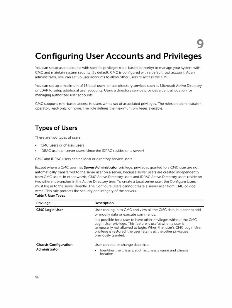
9Configuring User Accounts and PrivilegesYou can setup user accounts with specific privileges (role-based authority) to manage your system with CMC and maintain system security. By default, CMC is configured with a default root account. As an administrator, you can set up user accounts to allow other users to access the CMC.
You can set up a maximum of 16 local users, or use directory services such as Microsoft Active Directory or LDAP to setup additional user accounts. Using a directory service provides a central location for managing authorized user accounts.
CMC supports role-based access to users with a set of associated privileges. The roles are administrator, operator, read-only, or none. The role defines the maximum privileges available.
Types of Users
There are two types of users:
• CMC users or chassis users
• iDRAC users or server users (since the iDRAC resides on a server)
CMC and iDRAC users can be local or directory service users.
Except where a CMC user has Server Administrator privilege, privileges granted to a CMC user are not automatically transferred to the same user on a server, because server users are created independently from CMC users. In other words, CMC Active Directory users and iDRAC Active Directory users reside on two different branches in the Active Directory tree. To create a local server user, the Configure Users must log in to the server directly. The Configure Users cannot create a server user from CMC or vice versa. This rule protects the security and integrity of the servers.Table 7. User Types
Privilege Description
CMC Login User User can log in to CMC and view all the CMC data, but cannot add or modify data or execute commands.
It is possible for a user to have other privileges without the CMC Login User privilege. This feature is useful when a user is temporarily not allowed to login. When that user’s CMC Login User privilege is restored, the user retains all the other privileges previously granted.
Chassis Configuration Administrator
User can add or change data that:
• Identifies the chassis, such as chassis name and chassis location.
98
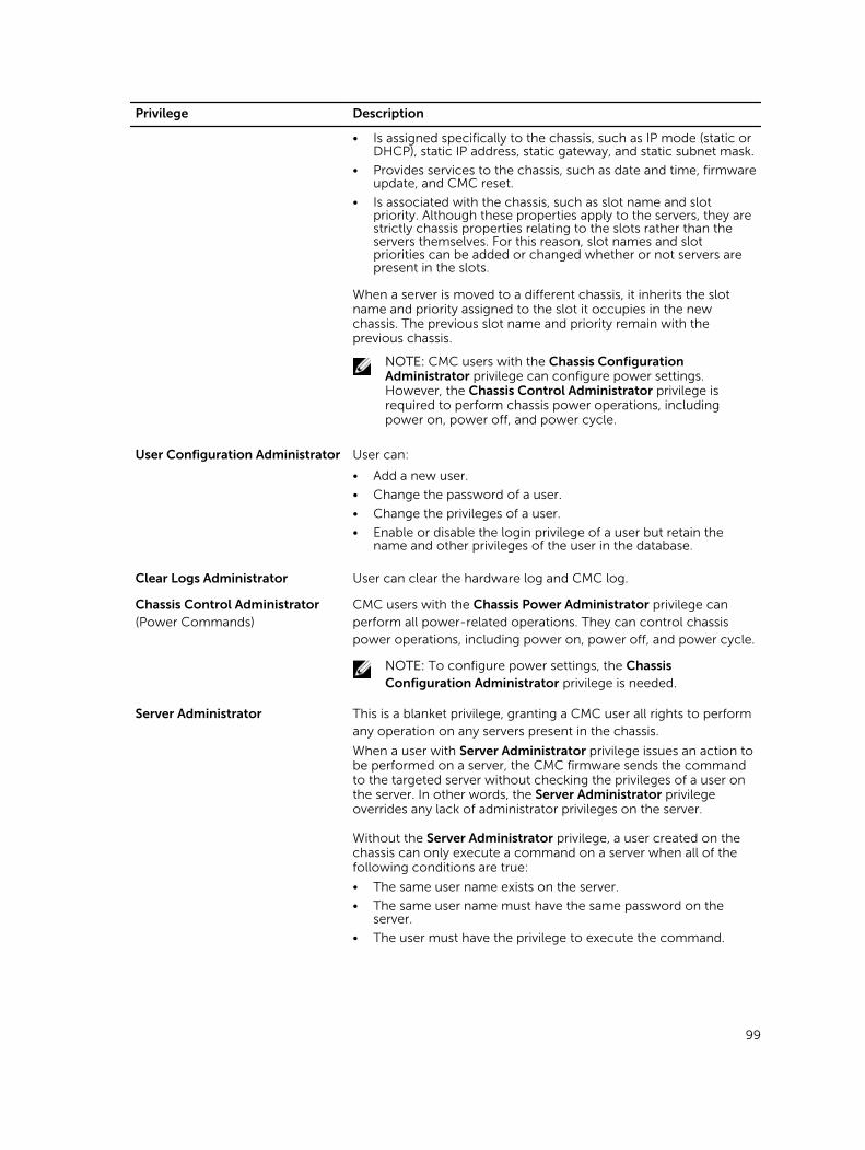
Privilege Description
• Is assigned specifically to the chassis, such as IP mode (static or DHCP), static IP address, static gateway, and static subnet mask.
• Provides services to the chassis, such as date and time, firmware update, and CMC reset.
• Is associated with the chassis, such as slot name and slot priority. Although these properties apply to the servers, they are strictly chassis properties relating to the slots rather than the servers themselves. For this reason, slot names and slot priorities can be added or changed whether or not servers are present in the slots.
When a server is moved to a different chassis, it inherits the slot name and priority assigned to the slot it occupies in the new chassis. The previous slot name and priority remain with the previous chassis.
NOTE: CMC users with the Chassis Configuration Administrator privilege can configure power settings. However, the Chassis Control Administrator privilege is required to perform chassis power operations, including power on, power off, and power cycle.
User Configuration Administrator User can:
• Add a new user.
• Change the password of a user.
• Change the privileges of a user.
• Enable or disable the login privilege of a user but retain the name and other privileges of the user in the database.
Clear Logs Administrator User can clear the hardware log and CMC log.
Chassis Control Administrator (Power Commands)
CMC users with the Chassis Power Administrator privilege can perform all power-related operations. They can control chassis power operations, including power on, power off, and power cycle.
NOTE: To configure power settings, the Chassis Configuration Administrator privilege is needed.
Server Administrator This is a blanket privilege, granting a CMC user all rights to perform any operation on any servers present in the chassis.
When a user with Server Administrator privilege issues an action to be performed on a server, the CMC firmware sends the command to the targeted server without checking the privileges of a user on the server. In other words, the Server Administrator privilege overrides any lack of administrator privileges on the server.
Without the Server Administrator privilege, a user created on the chassis can only execute a command on a server when all of the following conditions are true:
• The same user name exists on the server.
• The same user name must have the same password on the server.
• The user must have the privilege to execute the command.
99
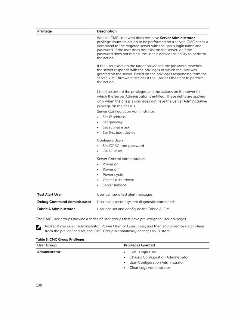
Privilege Description
When a CMC user who does not have Server Administrator privilege issues an action to be performed on a server, CMC sends a command to the targeted server with the user’s login name and password. If the user does not exist on the server, or if the password does not match, the user is denied the ability to perform the action.
If the user exists on the target server and the password matches, the server responds with the privileges of which the user was granted on the server. Based on the privileges responding from the server, CMC firmware decides if the user has the right to perform the action.
Listed below are the privileges and the actions on the server to which the Server Administrator is entitled. These rights are applied only when the chassis user does not have the Server Administrative privilege on the chassis.
Server Configuration Administrator:
• Set IP address
• Set gateway
• Set subnet mask
• Set first boot device
Configure Users:
• Set iDRAC root password
• iDRAC reset
Server Control Administrator:
• Power on
• Power off
• Power cycle
• Graceful shutdown
• Server Reboot
Test Alert User User can send test alert messages.
Debug Command Administrator User can execute system diagnostic commands.
Fabric A Administrator User can set and configure the Fabric A IOM.
The CMC user groups provide a series of user groups that have pre-assigned user privileges.
NOTE: If you select Administrator, Power User, or Guest User, and then add or remove a privilege from the pre-defined set, the CMC Group automatically changes to Custom.
Table 8. CMC Group Privileges
User Group Privileges Granted
Administrator • CMC Login User
• Chassis Configuration Administrator
• User Configuration Administrator
• Clear Logs Administrator
100
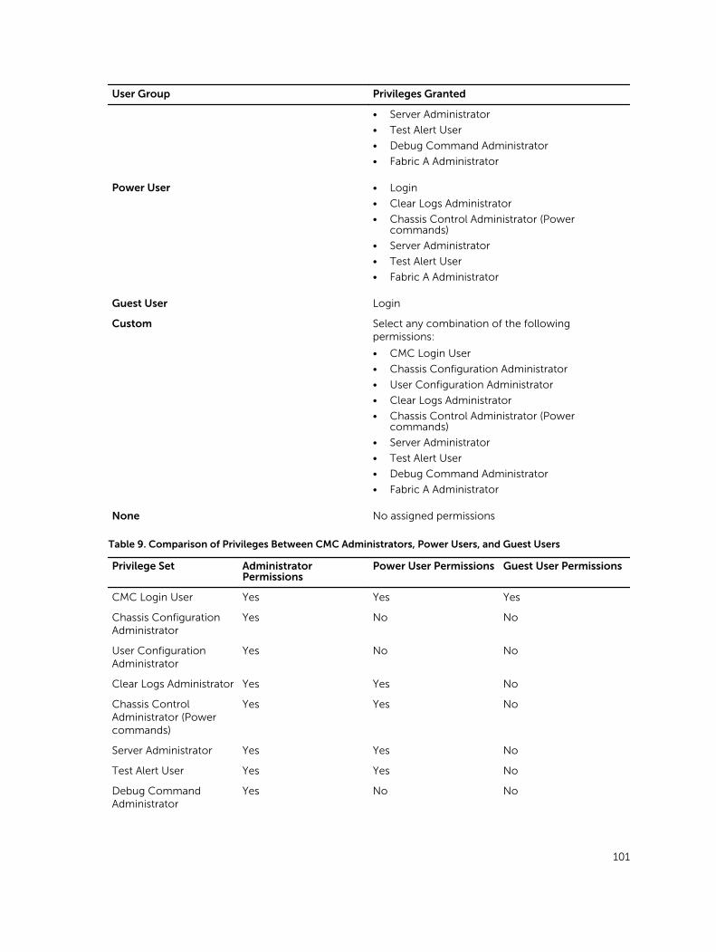
User Group Privileges Granted
• Server Administrator
• Test Alert User
• Debug Command Administrator
• Fabric A Administrator
Power User • Login
• Clear Logs Administrator
• Chassis Control Administrator (Power commands)
• Server Administrator
• Test Alert User
• Fabric A Administrator
Guest User Login
Custom Select any combination of the following permissions:
• CMC Login User
• Chassis Configuration Administrator
• User Configuration Administrator
• Clear Logs Administrator
• Chassis Control Administrator (Power commands)
• Server Administrator
• Test Alert User
• Debug Command Administrator
• Fabric A Administrator
None No assigned permissions
Table 9. Comparison of Privileges Between CMC Administrators, Power Users, and Guest Users
Privilege Set Administrator Permissions
Power User Permissions Guest User Permissions
CMC Login User Yes Yes Yes
Chassis Configuration Administrator
Yes No No
User Configuration Administrator
Yes No No
Clear Logs Administrator Yes Yes No
Chassis Control Administrator (Power commands)
Yes Yes No
Server Administrator Yes Yes No
Test Alert User Yes Yes No
Debug Command Administrator
Yes No No
101
Privilege Set Administrator Permissions
Power User Permissions Guest User Permissions
Fabric A Administrator Yes Yes No
Modifying Root User Administrator Account SettingsFor added security, it is strongly recommended that you change the default password of the root (User 1) account. The root account is the default administrative account that is shipped with CMC.
To change the default password for the root account:
1. In the left pane, click Chassis Overview, and then click User Authentication.
2. On the Users page, in the User ID column, click 1.
NOTE: The user ID 1 is the root user account that is shipped by default with CMC. This cannot be changed.
3. On the User Configuration page, select the Change Password option.
4. Type the new password in the Password field, and then type the same password in Confirm Password.
5. Click Apply. The password is changed for the 1 user ID.
Configuring Local Users
You can configure up to 16 local users in CMC with specific access privileges. Before you create a CMC local user, verify if any current users exist. You can set user names, passwords, and roles with the privileges for these users. The user names and passwords can be changed using any of the CMC–secured interfaces such as, web interface, RACADM, and WS-MAN.
Configuring Local Users Using CMC Web Interface
NOTE: You must have Configure Users permission to create a CMC user.
To add and configure local CMC users:
1. In the left pane, click Chassis Overview, and then click User Authentication.
2. On the Local Users page, in the User ID column, click a user ID number. The User Configuration page is displayed.
NOTE: User ID 1 is the root user account that is shipped by default with a CMC. This cannot be changed.
3. Enable the user ID and specify the user name, password, and access privileges for the user. For more information about the options, see the Online Help.
4. Click Apply. The user is created with appropriate privileges.
Configure Local Users Using RACADM
NOTE: You must be logged in as a root user to execute RACADM commands on a remote Linux system.
You can configure up to 16 users in the CMC property database. Before you manually enable a CMC user, verify if any current users exist.
102
If you are configuring a new CMC or if you have used the racadm racresetcfg command, the only
current user account is default root account. The racresetcfg subcommand resets all configuration
parameters to the default values. Any earlier changes are lost.
NOTE: Users can be enabled and disabled over time, and disabling a user does not delete the user from the database.
To verify if a user exists, open a Telnet/SSH text console to the CMC, log in, and then type the following command once for each index of 1–16:
racadm getconfig -g cfgUserAdmin -i <index>NOTE: You can also type racadm getconfig -f <myfile.cfg> and view or edit the myfile.cfg
file, which includes all the CMC configuration parameters.
Several parameters and object IDs are displayed with their current values. Two objects of importance are:
# cfgUserAdminIndex=XXcfgUserAdminUserName=
If the cfgUserAdminUserName object has no value, that index number, which is indicated by the
cfgUserAdminIndex object, is available for use. If a name is displayed after the "=", that index is taken
by that user name.
When you manually enable or disable a user with the racadm config subcommand, you must specify
the index with the -i option.
The "#" character in the command objects indicates that it is a read-only object. Also, if you use the racadm config -f racadm.cfg command to specify any number of groups/objects to write, the
index cannot be specified. A new user is added to the first available index. This behavior allows more flexibility in configuring a second CMC with the same settings as the main CMC.
Configuring Active Directory Users
If your company uses the Microsoft Active Directory software, you can configure the software to provide access to CMC, allowing you to add and control CMC user privileges to your existing users in your directory service. This is a licensed feature.
NOTE: On the following Operating Systems, you can recognize the users of CMC users by using Active Directory.
• Microsoft Windows 2000
• Microsoft Windows Server 2003
• Microsoft Windows Server 2008
You can configure user authentication through Active Directory to log in to the CMC. You can also provide role-based authority, which enables an administrator to configure specific privileges for each user.
Supported Active Directory Authentication Mechanisms
You can use Active Directory to define CMC user access using two methods:
• Standard schema solution that uses Microsoft’s default Active Directory group objects only.
103
• Extended schema solution that has customized Active Directory objects provided by Dell. All the access control objects are maintained in Active Directory. It provides maximum flexibility to configure user access on different CMCs with varying privilege levels.
Standard Schema Active Directory Overview
As shown in the following figure, using standard schema for Active Directory integration requires configuration on both Active Directory and CMC.
In Active Directory, a standard group object is used as a role group. A user who has CMC access is a member of the role group. To give this user access to a specific CMC card, the role group name and its domain name need to be configured on the specific CMC card. The role and the privilege level is defined on each CMC card and not in the Active Directory. You can configure up to five role groups in each CMC. The following table shows the default role group privileges.Table 10. : Default Role Group Privileges
Role Group Default Privilege Level Permissions Granted Bit Mask
1 None • CMC Login User
• Chassis Configuration Administrator
• User Configuration Administrator
• Clear Logs Administrator
• Chassis Control Administrator (Power Commands)
• Server Administrator
• Test Alert User
• Debug Command Administrator
• Fabric A Administrator
0x00000fff
2 None • CMC Login User
• Clear Logs Administrator
• Chassis Control Administrator (Power Commands)
• Server Administrator
• Test Alert User
• Fabric A Administrator
0x00000ed9
3 None CMC Login User 0x00000001
4 None No assigned permissions 0x00000000
5 None No assigned permissions 0x00000000
NOTE: The Bit Mask values are used only when setting Standard Schema with the RACADM.
104
NOTE: For more information about user privileges, see Types of Users.
Configuring Standard Schema Active Directory
To configure CMC for an Active Directory login access:
1. On an Active Directory server (domain controller), open Active Directory Users and Computers Snap-in.
2. Using the CMC Web interface or RACADM:
a. Create a group or select an existing group.b. Configure the role privileges.
3. Add the Active Directory user as a member of the Active Directory group to access CMC.
Extended Schema Active Directory Overview
Using the extended schema solution requires the Active Directory schema extension.
Configuring Extended Schema Active Directory
To configure Active Directory to access CMC:
1. Extend the Active Directory schema.
2. Extend the Active Directory Users and Computers Snap-in.
3. Add CMC users and their privileges to Active Directory.
4. Enable SSL on each of your domain controllers.
5. Configure CMC Active Directory properties using CMC web interface or RACADM.
Configuring Generic LDAP Users
CMC provides a generic solution to support Lightweight Directory Access Protocol (LDAP)-based authentication. This feature does not require any schema extension on your directory services.
A CMC administrator can now integrate the LDAP server user logins with CMC. This integration requires configuration on both LDAP server and CMC. On the LDAP server, a standard group object is used as a role group. A user who has CMC access becomes a member of the role group. Privileges are still stored on CMC for authorization similar to the working of the Standard Schema setup with Active Directory support.
To enable the LDAP user to access a specific CMC card, the role group name and its domain name must be configured on the specific CMC card. You can configure a maximum of five role groups in each CMC. A user has the option to be added to multiple groups within the directory service. If a user is a member of multiple groups, then the user obtains the privileges of all their groups.
Configuring the Generic LDAP Directory to Access CMC
The CMC's Generic LDAP implementation uses two phases in granting access to a user—user authentication, and then the user authorization.
Configuring Generic LDAP Directory Service Using CMC Web Interface
To configure the generic LDAP directory service:
105
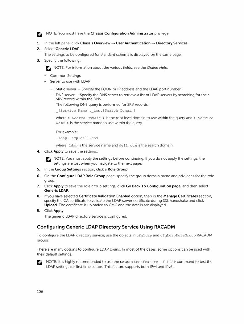
NOTE: You must have the Chassis Configuration Administrator privilege.
1. In the left pane, click Chassis Overview → User Authentication → Directory Services.
2. Select Generic LDAP.
The settings to be configured for standard schema is displayed on the same page.
3. Specify the following:
NOTE: For information about the various fields, see the Online Help.
• Common Settings
• Server to use with LDAP:
– Static server — Specify the FQDN or IP address and the LDAP port number.
– DNS server — Specify the DNS server to retrieve a list of LDAP servers by searching for their SRV record within the DNS.
The following DNS query is performed for SRV records:
_[Service Name]._tcp.[Search Domain]where < Search Domain > is the root level domain to use within the query and < Service Name > is the service name to use within the query.
For example:
_ldap._tcp.dell.comwhere ldap is the service name and dell.com is the search domain.
4. Click Apply to save the settings.
NOTE: You must apply the settings before continuing. If you do not apply the settings, the settings are lost when you navigate to the next page.
5. In the Group Settings section, click a Role Group.
6. On the Configure LDAP Role Group page, specify the group domain name and privileges for the role group.
7. Click Apply to save the role group settings, click Go Back To Configuration page, and then select Generic LDAP.
8. If you have selected Certificate Validation Enabled option, then in the Manage Certificates section, specify the CA certificate to validate the LDAP server certificate during SSL handshake and click Upload. The certificate is uploaded to CMC and the details are displayed.
9. Click Apply.
The generic LDAP directory service is configured.
Configuring Generic LDAP Directory Service Using RACADM
To configure the LDAP directory service, use the objects in cfgLdap and cfgLdapRoleGroup RACADM
groups.
There are many options to configure LDAP logins. In most of the cases, some options can be used with their default settings.
NOTE: It is highly recommended to use the racadm testfeature -f LDAP command to test the
LDAP settings for first time setups. This feature supports both IPv4 and IPv6.
106

The required property changes include enabling LDAP logins, setting the server FQDN or IP, and configuring the base DN of the LDAP server.
• $ racadm config -g cfgLDAP -o cfgLDAPEnable 1• $ racadm config -g cfgLDAP -o cfgLDAPServer 192.168.0.1• $ racadm config -g cfgLDAP -o cfgLDAPBaseDN dc=
company,dc=com
CMC can be configured to optionally query a DNS server for SRV records. If the cfgLDAPSRVLookupEnable property is enabled, the cfgLDAPServer property is ignored. The following
query is used to search the DNS for SRV records:
_ldap._tcp.domainname.comldap in the above query is the cfgLDAPSRVLookupServiceName property.
cfgLDAPSRVLookupDomainName is configured to be domainname.com.
For more information about the RACADM commands, see the Dell Chassis Management Controller for PowerEdge FX2/FX2s RACADM Command Line Reference Guide available at dell.com/support/manuals.
107
10Configuring CMC For Single Sign-On Or Smart Card LoginThis section provides information to configure CMC for Smart Card login and Single Sign-On (SSO) login for Active Directory users.
SSO uses Kerberos as an authentication method allowing users, who have signed in as an automatic- or single sign-on to subsequent applications such as Exchange. For single sign-on login, CMC uses the client system’s credentials, which are cached by the operating system after you log in using a valid Active Directory account.
Two-factor-authentication, provides a higher-level of security by requiring users to have a password or PIN, and a physical card containing a private key or digital certificate. Kerberos uses this two-factor authentication mechanism allowing systems to prove their authenticity.
NOTE: Selecting a login method does not set policy attributes with respect to other login interfaces, for example, SSH. You must set other policy attributes for other login interfaces also. If you want to disable all other login interfaces, navigate to the Services page and disable all (or some) the login interfaces.
Microsoft Windows 2000, Windows XP, Windows Server 2003, Windows Vista, Windows 7, and Windows Server 2008 can use Kerberos as the authentication mechanism for SSO and smart card login.
For information about Kerberos, see the Microsoft Website.
System Requirements
To use the Kerberos authentication, the network must include:
• DNS server
• Microsoft Active Directory Server
NOTE: If you are using Active Directory on Microsoft Windows 2003, make sure that you have the latest service packs and patched installed on the client system. If you are using Active Directory on Microsoft Windows 2008, make sure that you have installed SP1 along with the following hot fixes:
Windows6.0-KB951191-x86.msu for the KTPASS utility. Without this patch the utility generates bad keytab files.
Windows6.0-KB957072-x86.msu for using GSS_API and SSL transactions during an LDAP bind.
• Kerberos Key Distribution Center (packaged with the Active Directory Server software).
• DHCP server (recommended).
• The DNS server reverse zone must have an entry for the Active Directory server and CMC.
108
Client Systems
• For only Smart Card login, the client system must have the Microsoft Visual C++ 2005 redistributable. For more information see www.microsoft.com/downloads/details.aspx?FamilyID= 32BC1BEEA3F9-4C13-9C99-220B62A191EE&displaylang=en
• For Single Sign-On or smart card login, the client system must be a part of the Active Directory domain and Kerberos Realm.
CMC
• Each CMC must have an Active Directory account.
• CMC must be a part of the Active Directory domain and Kerberos Realm.
Prerequisites For Single Sign-On Or Smart Card Login
The pre-requisites to configure SSO or Smart Card logins are:
• Setup the Kerberos realm and Key Distribution Center (KDC) for Active Directory (ksetup).
• A robust NTP and DNS infrastructure to avoid issues with clock drift and reverse lookup.
• Configure CMC with Active Directory standard schema role group with authorized members.
• For smart card, create Active Directory users for each CMC, configured to use Kerberos DES encryption but not pre-authentication.
• Configure the browser for SSO or smart card login.
• Register the CMC users to the Key Distribution Center with Ktpass (this also outputs a key to upload to CMC).
Generating Kerberos Keytab FileTo support the SSO and smart card login authentication, CMC supports Windows Kerberos network. The ktpass tool is used to create the Service Principal Name (SPN) bindings to a user account and export the trust information into a MIT-style Kerberos keytab file. For more information about the ktpass utility, see the Microsoft Website.
Before generating a keytab file, you must create an Active Directory user account for use with the -mapuser option of the ktpass command. You must use the same name as the CMC DNS name to which you upload the generated keytab file.
To generate a keytab file using the ktpass tool:
1. Run the ktpass utility on the domain controller (Active Directory server), where you want to map CMC to a user account in Active Directory.
2. Use the following ktpass command to create the Kerberos keytab file:
C:\>ktpass -princ HTTP/cmcname.domain_name.com@REALM_NAME.COM - mapuser dracname -crypto DES-CBC-MD5 -ptype KRB5_NT_PRINCIPAL -pass * -out c:\krbkeytab
NOTE: The cmcname.domainname.com must be in lower case as required by RFC and the
@REALM_NAME must be in uppercase. In addition, CMC supports the DES-CBC-MD5 type of
cryptography for Kerberos authentication.
A keytab file is generated that must be uploaded to CMC.
109
NOTE: The keytab contains an encryption key and must be kept secure. For more information about the ktpass utility, see the Microsoft Website.
Configuring CMC For Active Directory Schema
For information about configuring CMC for Active Directory standard schema, see Configuring Standard Schema Active Directory.
For information about configuring CMC for Extended Schema Active Directory, see Extended Schema Active Directory Overview.
Configuring Browser For SSO Login
Single Sign-On (SSO) is supported on Internet Explorer versions 6.0 and later, and Firefox versions 3.0 and later.
NOTE: The following instructions are applicable only if CMC uses Single Sign-On with Kerberos authentication.
Internet Explorer
To edit the exception list in Internet Explorer:
1. Start Internet Explorer.
2. Click Tools → Internet Options → Connections.
3. In the Local Area Network (LAN) settings section, click LAN Settings.
4. In the Proxy server section, select the Use a proxy server for your LAN (These settings will not apply to dial-up or VPN connections) option, and then click Advanced.
5. In the Exceptions section, add the addresses for CMCs and iDRACs on the management network to the semicolon-separated list. You can use DNS names and wildcards in your entries.
Mozilla FireFox
To edit the exception list in Mozilla Firefox version 19.0:
1. Start Mozilla Firefox.
2. Click Tools → Options (for systems running on Windows), or click Edit → Preferences (for systems running on Linux).
3. Click Advanced, and then click the Network tab.
4. Click Settings.
5. Select Manual Proxy Configuration.
6. In the No Proxy for field, type the addresses for CMCs and iDRACs on the management network to the comma-separated list. You can use DNS names and wildcards in your entries.
Configuring Browser For Smart Card Login
Internet Explorer — Make sure that the Internet Browser is configured to download Active-X plug-ins.
110
Configuring CMC SSO Login Or Smart Card Login For Active Directory Users Using RACADM
In addition to the steps performed while configuring Active Directory, run the following command to enable SSO:
racadm -g cfgActiveDirectory -o cfgADSSOEnable 1
In addition to the steps performed while configuring Active Directory, use the following objects to enable smart card login:
• cfgSmartCardLogonEnable• cfgSmartCardCRLEnable
Configuring CMC SSO Or Smart Card Login For Active Directory Users Using Web InterfaceTo configure Active Directory SSO or smart card login for CMC:
NOTE: For information about the options, see the CMC for Dell PowerEdge FX2/FX2s Online Help.
1. While configuring Active Directory to setup a user account, perform the following additional steps:
• Upload the keytab file.
• To enable SSO, select the Enable Single Sign-On option.
• To enable smart card login, select the Enable Smart-Card Login option.
NOTE: If these two options are selected, all command line out-of-band interfaces, including secure shell (SSH), Telnet, Serial, and remote RACADM remain unchanged .
2. Click Apply.
The settings are saved.
You can test the Active Directory using Kerberos authentication using the RACADM command:
testfeature -f adkrb -u <user>@<domain>where <user> is a valid Active Directory user account.
A command success indicates that CMC is able to acquire Kerberos credentials and access the user's Active Directory account. If the command is not successful, resolve the error and run the command again. For more information, see the Dell Chassis Management Controller for PowerEdge FX2/FX2s RACADM Command Line Reference Guide on dell.com/support/manuals.
Uploading Keytab FileThe Kerberos keytab file serves as the CMC's user name and password credentials to the Kerberos Data Center (KDC), which in turns allows access to the Active Directory. Each CMC in the Kerberos realm must be registered with the Active Directory and must have a unique keytab file.
You can upload a Kerberos Keytab generated on the associated Active Directory Server. You can generate the Kerberos Keytab from the Active Directory Server by executing the ktpass.exe utility. This keytab establishes a trust relationship between the Active Directory Server and CMC.
111
To upload the keytab file:
1. In the left pane, click Chassis Overview → User Authentication → Directory Services.
2. Select Microsoft Active Directory (Standard Schema).
3. In the Kerberos Keytab section, click Browse, select a keytab file, and click Upload.
When the upload is complete, a message is displayed indicating whether the keytab file is successfully uploaded or not.
Configuring CMC SSO Login Or Smart Card Login For Active Directory Users Using RACADM
In addition to the steps performed while configuring Active Directory, run the following command to enable SSO:
racadm -g cfgActiveDirectory -o cfgADSSOEnable 1
In addition to the steps performed while configuring Active Directory, use the following objects to enable smart card login:
• cfgSmartCardLogonEnable• cfgSmartCardCRLEnable
112
11Configuring CMC to Use Command Line ConsolesThis section provides information about the CMC command line console (or serial/Telnet/Secure Shell console) features, and explains how to set up the system so that you can perform systems management actions through the console. For information about using the RACADM commands in CMC through the command line console, see Chassis Management Controller for PowerEdge FX2/FX2s RACADM Command Line Reference Guide.
CMC Command Line Console Features
The CMC supports the following serial, Telnet, and SSH console features:
• One serial client connection and up to four simultaneous Telnet client connections.
• Up to four simultaneous Secure Shell (SSH) client connections.
• RACADM command support.
• Built-in connect command connecting to the serial console of servers and I/O module; also available as racadm connect.
• Command line editing and history.
• Session timeout control on all console interfaces.
CMC Command Line Interface Commands
When you connect to the CMC command line, you can enter these commands:Table 11. CMC Command Line Commands
Command Description
racadm RACADM commands begin with the keyword racadm, and then followed by a subcommand. For
more information, see Dell Chassis Management Controller for PowerEdge FX2/FX2s RACADM Command Line Reference Guide.
connect Connects to the serial console of a server or I/O module. For more information, see Connecting to Servers or IO Module Using Connect Command.
NOTE: You can also use the connect RACADM command.
113
Command Description
exit, logout, and quit All the commands perform the same action. They end the current session and return to a login commond line interface.
Using Telnet Console With CMC
You can have up to four Telnet sessions with CMC at a time.
If your management station is running Microsoft Windows XP or Microsoft Windows Server 2003, you may experience an issue with the characters in a CMC Telnet session. This issue may occur as a frozen login where the return key does not respond and the password prompt does not appear.
To fix this issue, download hotfix 824810 from support.microsoft.com. For more information, you can also see Microsoft Knowledge Base article 824810.
Using SSH With CMC
SSH is a command line session that includes the same capabilities as a Telnet session, but with session negotiation and encryption to improve security. CMC supports SSH version 2 with password authentication. SSH is enabled on the CMC by default.
NOTE: CMC does not support SSH version 1.
When an error occurs during the CMC login, the SSH client issues an error message. The message text is dependent on the client and is not controlled by CMC. Review the RACLog messages to determine the cause of the failure.
NOTE: OpenSSH must be run from a VT100 or ANSI terminal emulator on Windows. You can also
run OpenSSH using Putty.exe. Running OpenSSH at the Windows command prompt does not
provide full functionality (that is, some keys do not respond and no graphics are displayed). On servers that run Linux, run SSH client services to connect to CMC with any shell.
Four simultaneous SSH sessions are supported at a time. The session timeout is controlled by the cfgSsnMgtSshIdleTimeout property. For more information about the RACADM commands, see the
Dell Chassis Management Controller for PowerEdge FX2/FX2s RACADM Command Line Reference Guide available at dell.com/support/Manuals.
CMC also supports Public Key Authentication (PKA) over SSH. This authentication method improves SSH scripting automation by removing the need to embed or prompt for user ID/password.
SSH is enabled by default. If SSH is disabled, then you can enable it using any other supported interface.
Supported SSH Cryptography Schemes
To communicate with CMC using SSH protocol, it supports multiple cryptography schemes listed in the following table.
114
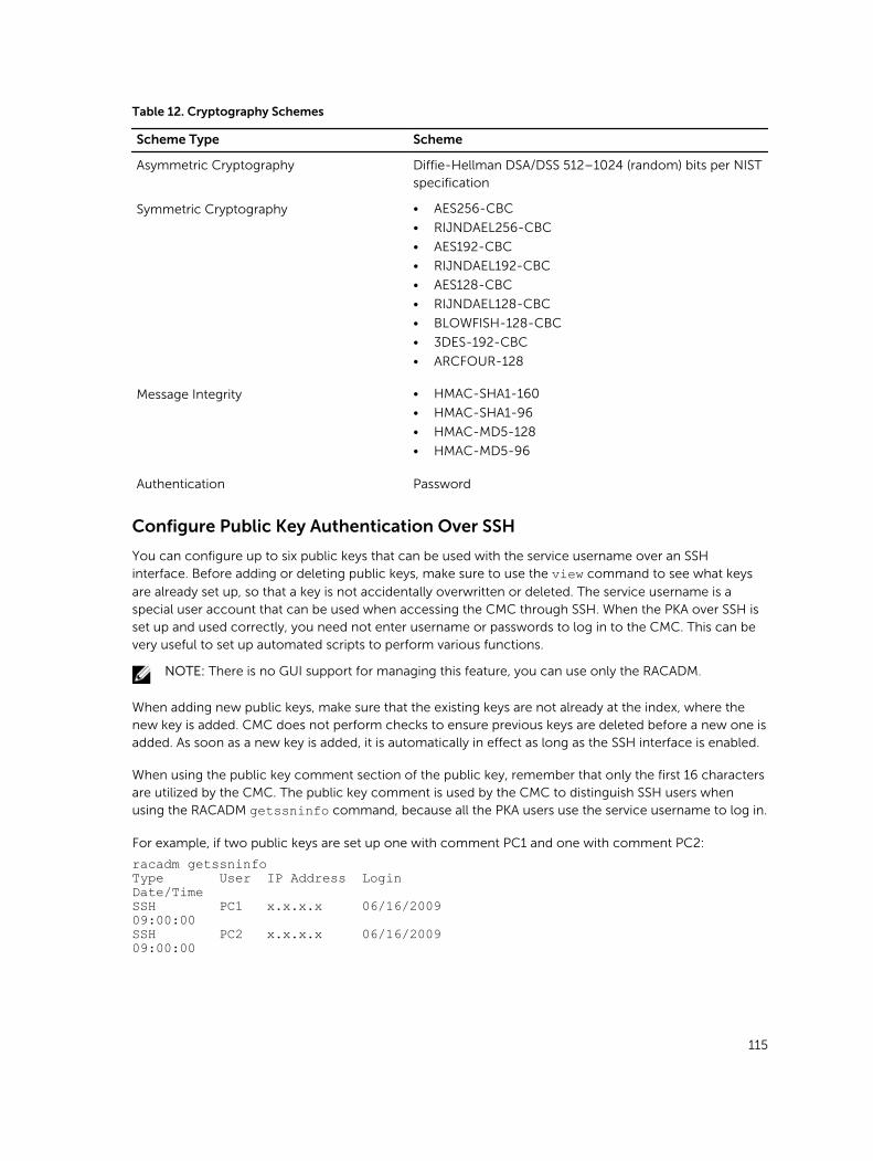
Table 12. Cryptography Schemes
Scheme Type Scheme
Asymmetric Cryptography Diffie-Hellman DSA/DSS 512–1024 (random) bits per NIST specification
Symmetric Cryptography • AES256-CBC
• RIJNDAEL256-CBC
• AES192-CBC
• RIJNDAEL192-CBC
• AES128-CBC
• RIJNDAEL128-CBC
• BLOWFISH-128-CBC
• 3DES-192-CBC
• ARCFOUR-128
Message Integrity • HMAC-SHA1-160
• HMAC-SHA1-96
• HMAC-MD5-128
• HMAC-MD5-96
Authentication Password
Configure Public Key Authentication Over SSH
You can configure up to six public keys that can be used with the service username over an SSH interface. Before adding or deleting public keys, make sure to use the view command to see what keys
are already set up, so that a key is not accidentally overwritten or deleted. The service username is a special user account that can be used when accessing the CMC through SSH. When the PKA over SSH is set up and used correctly, you need not enter username or passwords to log in to the CMC. This can be very useful to set up automated scripts to perform various functions.
NOTE: There is no GUI support for managing this feature, you can use only the RACADM.
When adding new public keys, make sure that the existing keys are not already at the index, where the new key is added. CMC does not perform checks to ensure previous keys are deleted before a new one is added. As soon as a new key is added, it is automatically in effect as long as the SSH interface is enabled.
When using the public key comment section of the public key, remember that only the first 16 characters are utilized by the CMC. The public key comment is used by the CMC to distinguish SSH users when using the RACADM getssninfo command, because all the PKA users use the service username to log in.
For example, if two public keys are set up one with comment PC1 and one with comment PC2:
racadm getssninfoType User IP Address LoginDate/TimeSSH PC1 x.x.x.x 06/16/200909:00:00SSH PC2 x.x.x.x 06/16/200909:00:00
115
For more information about the sshpkauth, see the Chassis Management Controller for PowerEdge
FX2/FX2s Command Line Reference Guide.
Configuring Terminal Emulation Software
CMC supports a serial text console that can be launched using any terminal emulation software. Following are the examples of terminal emulation software that can used to connect to CMC.
1. Linux Minicom
2. Hilgraveve’s HyperTerminal for Windows
Connect one end of the serial null modem cable (present at both ends) to the serial connector on the back of the chassis. Connect the other end of the cable to management station serial port. For more information on connecting cables, refer to the back panel of the chassis in Chassis Overview section.
Configure your terminal emulation software with the following parameters:
• Baud rate: 115200
• Port: COM1
• Data: 8 bit
• Parity: None
• Stop: 1 bit
• Hardware flow control: Yes
• Software flow control: No
Connecting to Servers or I/O Module Using Connect Command
CMC can establish a connection to redirect the serial console of a server or I/O module.
For servers, serial console redirection can be accomplished using:
• CMC command line interface (CLI) or the RACADM connect command. For more information about running the RACADM commands, see the Chassis Management Controller for PowerEdge FX2/FX2s RACADM Command Line Reference Guide.
• iDRAC Web interface serial console redirection feature.
• iDRAC Serial Over LAN (SOL) functionality.
In a serial, Telnet, SSH console, CMC supports the connect command to establish a serial connection to
a server or I/O module. The server serial console contains both the BIOS boot and setup screens, and the operating system serial console. For the I/O module, the switch serial console is available. There is a single IOM on the chassis.
CAUTION: When run from the CMC serial console, the connect -b option stays connected until the CMC resets. This connection is a potential security risk.
NOTE: The connect command provides the –b (binary) option. The –b option passes raw binary
data, and cfgSerialConsoleQuitKey is not used. Additionally, when connecting to a server using
the CMC serial console, transitions in the DTR signal (for example, if the serial cable is removed to connect a debugger) will not result in you exiting the application.
116
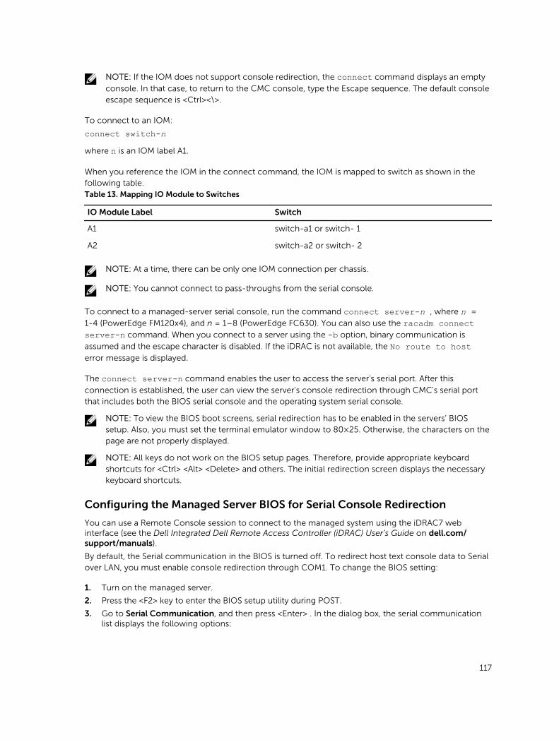
NOTE: If the IOM does not support console redirection, the connect command displays an empty
console. In that case, to return to the CMC console, type the Escape sequence. The default console escape sequence is <Ctrl><\>.
To connect to an IOM:
connect switch-nwhere n is an IOM label A1.
When you reference the IOM in the connect command, the IOM is mapped to switch as shown in the following table.Table 13. Mapping IO Module to Switches
IO Module Label Switch
A1 switch-a1 or switch- 1
A2 switch-a2 or switch- 2
NOTE: At a time, there can be only one IOM connection per chassis.
NOTE: You cannot connect to pass-throughs from the serial console.
To connect to a managed-server serial console, run the command connect server-n , where n =
1-4 (PowerEdge FM120x4), and n = 1–8 (PowerEdge FC630). You can also use the racadm connect server-n command. When you connect to a server using the -b option, binary communication is
assumed and the escape character is disabled. If the iDRAC is not available, the No route to host error message is displayed.
The connect server-n command enables the user to access the server's serial port. After this
connection is established, the user can view the server's console redirection through CMC's serial port that includes both the BIOS serial console and the operating system serial console.
NOTE: To view the BIOS boot screens, serial redirection has to be enabled in the servers’ BIOS setup. Also, you must set the terminal emulator window to 80×25. Otherwise, the characters on the page are not properly displayed.
NOTE: All keys do not work on the BIOS setup pages. Therefore, provide appropriate keyboard shortcuts for <Ctrl> <Alt> <Delete> and others. The initial redirection screen displays the necessary keyboard shortcuts.
Configuring the Managed Server BIOS for Serial Console Redirection
You can use a Remote Console session to connect to the managed system using the iDRAC7 web interface (see the Dell Integrated Dell Remote Access Controller (iDRAC) User’s Guide on dell.com/support/manuals).
By default, the Serial communication in the BIOS is turned off. To redirect host text console data to Serial over LAN, you must enable console redirection through COM1. To change the BIOS setting:
1. Turn on the managed server.
2. Press the <F2> key to enter the BIOS setup utility during POST.
3. Go to Serial Communication, and then press <Enter> . In the dialog box, the serial communication list displays the following options:
117
• off
• on without console redirection
• on with console redirection via COM1
To navigate between these options, press the appropriate arrow keys.
NOTE: Make sure that the On with console redirection via COM1 option is selected.
4. Enable Redirection After Boot (default value is disabled). This option enables BIOS console redirection across subsequent reboots.
5. Save the changes and exit.
The managed system restarts.
Configuring Windows for Serial Console Redirection
There is no configuration necessary for servers running the Microsoft Windows Server versions, starting with Windows Server 2003. Windows receives information from the BIOS, and enable the Special Administration Console (SAC) console one COM1.
Configuring Linux for Server Serial Console Redirection During Boot
The following steps are specific to the Linux GRand Unified Bootloader (GRUB). Similar changes are necessary for using a different boot loader.
NOTE: When you configure the client VT100 emulation window, set the window or application that is displaying the redirected console to 25 rows×80 columns to make sure proper text is displayed. Else, some text screens will appear distorted.
Edit the /etc/grub.conf file as follows:
1. Locate the general setting sections in the file and type the following two new lines:
serial --unit=1 --speed=57600terminal --timeout=10 serial
2. Append two options to the kernel line:
kernel console=ttyS1,576003. If the /etc/grub.conf contains a splashimage directive, comment it out.
The following example shows the changes described in this procedure.
# grub.conf generated by anaconda## Note that you do not have to rerun grub after makingchanges# to this file# NOTICE: You do not have a /boot partition. Thismeans that# all kernel and initrd paths are relative to/, e.g.# root (hd0,0)# kernel /boot/vmlinuz-version ro root=/dev/sdal# initrd /boot/initrd-version.img##boot=/dev/sdadefault=0timeout=10#splashimage=(hd0,2)/grub/splash.xpm.gzserial --unit=1 --speed=57600
118
terminal --timeout=10 serialtitle Red Hat Linux Advanced Server (2.4.9-e.3smp)root (hd0,0)kernel /boot/vmlinuz-2.4.9-e.3smp ro root=/dev/sda1 hda=ide-scsi console=ttyS0 console=ttyS1,57600initrd /boot/initrd-2.4.9-e.3smp.imgtitle Red Hat Linux Advanced Server-up (2.4.9-e.3)root (hd0,00)kernel /boot/vmlinuz-2.4.9-e.3 ro root=/dev/sda1initrd /boot/initrd-2.4.9-e.3.imgWhen you edit the /etc/grub.conf file, follow these guidelines:
• Disable GRUB's graphical interface and use the text-based interface. Else, the GRUB screen is not displayed in console redirection. To disable the graphical interface, comment out the line starting with splashimage.
• To start multiple GRUB options to start console sessions through the serial connection, add the following line to all options:
console=ttyS1,57600The example shows console=ttyS1,57600 added to only the first option.
Configuring Linux for Server Serial Console Redirection After Boot
Edit the /etc/inittab file as follows:
Add a new line to configure agetty on the COM2 serial port:
co:2345:respawn:/sbin/agetty -h -L 57600 ttyS1ansiThe following example shows the file with the new line.
## inittab This file describes how the INIT process# should set up the system in a certain# run-level.## Author: Miquel van Smoorenburg# Modified for RHS Linux by Marc Ewing and# Donnie Barnes## Default runlevel. The runlevels used by RHS are:# 0 - halt (Do NOT set initdefault to this)# 1 - Single user mode# 2 - Multiuser, without NFS (The same as 3, if you# do not have networking)# 3 - Full multiuser mode# 4 - unused# 5 - X11# 6 - reboot (Do NOT set initdefault to this)#id:3:initdefault:# System initialization.si::sysinit:/etc/rc.d/rc.sysinitl0:0:wait:/etc/rc.d/rc 0l1:1:wait:/etc/rc.d/rc 1l2:2:wait:/etc/rc.d/rc 2l3:3:wait:/etc/rc.d/rc 3l4:4:wait:/etc/rc.d/rc 4l5:5:wait:/etc/rc.d/rc 5
119

l6:6:wait:/etc/rc.d/rc 6# Things to run in every runlevel.ud::once:/sbin/update# Trap CTRL-ALT-DELETEca::ctrlaltdel:/sbin/shutdown -t3 -r now# When our UPS tells us power has failed, assume wehave a few# minutes of power left. Schedule a shutdown for 2minutes from now.# This does, of course, assume you have powerinstalled and your# UPS is connected and working correctly.pf::powerfail:/sbin/shutdown -f -h +2 "Power Failure;System Shutting Down"# If power was restored before the shutdown kicked in,cancel it.pr:12345:powerokwait:/sbin/shutdown -c "PowerRestored; Shutdown Cancelled"# Run gettys in standard runlevelsco:2345:respawn:/sbin/agetty -h -L 57600 ttyS1 ansi1:2345:respawn:/sbin/mingetty tty12:2345:respawn:/sbin/mingetty tty23:2345:respawn:/sbin/mingetty tty34:2345:respawn:/sbin/mingetty tty45:2345:respawn:/sbin/mingetty tty56:2345:respawn:/sbin/mingetty tty6
# Run xdm in runlevel 5# xdm is now a separate servicex:5:respawn:/etc/X11/prefdm -nodaemonEdit the /etc/securettyfile as follows:
Add a new line, with the name of the serial tty for COM2:
ttyS1
The following example shows a sample file with the new line.
vc/1vc/2vc/3vc/4vc/5vc/6vc/7vc/8vc/9vc/10vc/11tty1tty2tty3tty4tty5tty6tty7tty8tty9tty10tty11ttyS1
120
12Using FlexAddress and FlexAddress Plus CardsThis section provides information about FlexAddress and how to use FlexAddress Plus card to configure FlexAddress.
NOTE: The FlexAddress feature is licensed. This feature license is included in the Enterprise License.
About FlexAddress
FlexAddress allows CMC to assign WWN/MAC IDs to a particular slot and override the factory IDs. Hence, if the server module is replaced, the slot based WWN/MAC IDs remain the same. This feature eliminates the need to reconfigure Ethernet network management tools, SAN resources, DHCP servers, and routers for various fabrics for a new server module.
Every server module is assigned unique WWN and/or MAC IDs as part of the manufacturing process. Without FlexAddress, if a server had to be replaced with another server module, the WWN/MAC IDs changes and Ethernet network management tools and SAN resources had to be reconfigured to identify the new server module.
If the server is inserted in a new slot or chassis, the server-assigned WWN/MAC is used unless that chassis has the FlexAddress feature enabled for the new slot. If you remove the server, it will revert to the server-assigned address.
Additionally, the override action only occurs when a server module is inserted in a FlexAddress enabled chassis; no permanent changes are made to the server module. If a server module is moved to a chassis that does not support FlexAddress, the factory-assigned WWN/MAC IDs is used.
CMC FX2/FX2S chassis is shipped with the FlexAddress Plus SD card, which supports FlexAddress, FlexAddress Plus, and Extended Storage features.
NOTE: Data contained on the FlexAddress Plus SD card is encrypted and may not be duplicated or altered in any manner, because it may inhibit system function and cause the system to not function properly.
NOTE: The use of a FlexAddress Plus SD card is limited to one chassis only. You cannot use the same FlexAddress Plus SD card on another chassis.
About FlexAddress Plus
Each FlexAddress Plus feature card contains unique pool of MAC/WWNs that allow the chassis to assign World Wide Name/Media Access Control (WWN/MAC) addresses to Fibre Channel and Ethernet devices. Chassis assigned WWN/MAC addresses are globally unique and specific to a server slot.
121
Before installing FlexAddress, you can determine the range of MAC addresses contained on a FlexAddress feature card by inserting the SD card into an USB Memory Card Reader and viewing the pwwn_mac.xml file. This clear text XML file on the SD card contains an XML tag mac_start that is the first starting hex
MAC address that is used for this unique MAC address range. The mac_count tag is the total number of
MAC addresses that the SD card allocates. To determine the total MAC range allocated, use the following formula:
<mac_start> + <mac_count> - 1 = <mac_end>
For example:
(starting_mac)00:18:8B:FF:DC:FA + (mac_count)0xCF – 1 = (ending_mac)00:18:8B:FF:DD:C8
NOTE: Lock the SD card prior to inserting in the USB Memory Card Reader to prevent accidently modifying any of the contents. You must unlock the SD card before inserting into CMC.
Verifying FlexAddress Activation
To view the FlexAddress feature activation status, run the following RACADM command:
racadm featurecard -s Feature Name = FlexAddress Date/time Activated = 05 Oct 2013 - 11:50:49 Feature installed from SD-card serial number = CN0H871T1374036T00MXA00 Feature Name = FlexAddressPlus Date/time Activated = 05 Oct 2013 - 11:50:49 Feature installed from SD-card serial number = CN0H871T1374036T00MXA00 Feature Name = ExtendedStorage Current Status = redundant, active Date/time Activated = 05 Oct 2013 - 11:50:58 Feature installed from SD-card serial number = CN0H871T1374036T00MXA00
If there are no active features on the chassis, the command returns a message: racadm feature -s No features active on the chassis
racadm feature -s No features active on the chassis
To view the SD card information:
$ racadm featurecard -sActive CMC:The feature card inserted is valid, serial number CN0H871T1374036T00MXA00The feature card contains the following feature(s) FlexAddress: bound FlexAddressPlus: bound ExtendedStorage: bound
Table 14. Status Messages Returned by the featurecard -s Command
Status Message Actions
No feature card inserted. Check CMC to verify that the SD card was properly inserted.
The feature card inserted is valid and contains the following feature(s) FlexAddress: bound.
No action required.
122
Status Message Actions
The feature card inserted is valid and contains the following feature(s) FlexAddress: bound to another chassis, svctag=ABC1234, SD card SN = 1122334455.
Remove the SD card; locate and install the SD card for the current chassis.
The feature card inserted is valid and contains the following feature(s) FlexAddress: not bound.
The feature card can be moved to another chassis or can be reactivated on the current chassis. To reactivate on the current chassis, enter racadm racreset until the CMC module with the feature
card installed becomes active.
Dell Feature Cards may contain more than one feature. Once any feature included on a Dell Feature Card has been activated on a chassis, any other features that may be included on that Dell Feature Card cannot be activated on a different chassis. In this case, the racadm feature -s command displays the following message for the affected features:
ERROR: One or more features on the SD card are active on another chassis
For more information on the feature and featurecard commands, see the Dell Chassis Management
Controller for PowerEdge FX2/FX2s RACADM Command Line Reference Guide.
Deactivating FlexAddress
The FlexAddress feature can be deactivated and the SD card returned to a pre-installation state by using a RACADM command. There is no deactivation function within the Web interface. Deactivation returns the SD card to its original state where it can be installed and activated in another chassis. The term FlexAddress, in this context, implies both FlexAddress and FlexAddressPlus.
NOTE: The SD card must be physically installed in CMC, and the chassis must be turned off before running the deactivation command.
If you run the deactivation command without installing an SD card, or with a card from a different chassis installed, the feature is deactivated and change is not made to the card.
To deactivate the FlexAddress feature and restore the SD card:
racadm feature -d -c flexaddressThe command returns the following status message if it is successfully deactivated:
feature FlexAddress is deactivated on the chassis successfully.
If the chassis is not turned off before running the command, the command throws the following error:
ERROR: Unable to deactivate the feature because the chassis is powered ON
NOTE: To activate the FlexAddress feature again, re-boot the CMC.
For further information about the command, see the feature command section of the Dell Chassis Management Controller for PowerEdge FX2/FX2s RACADM Command Line Reference Guide.
123
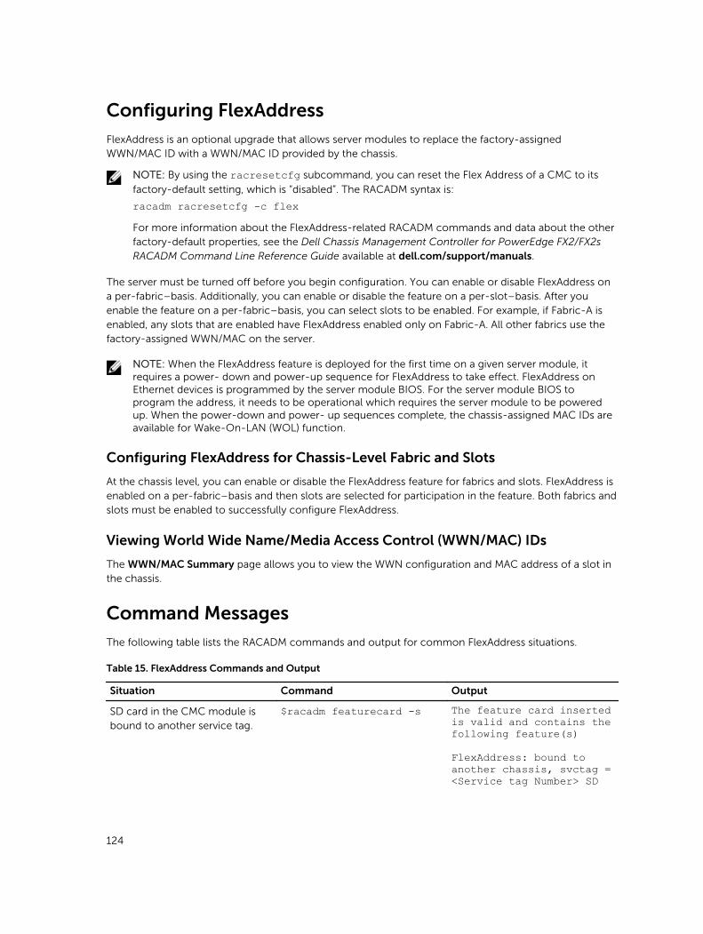
Configuring FlexAddress
FlexAddress is an optional upgrade that allows server modules to replace the factory-assigned WWN/MAC ID with a WWN/MAC ID provided by the chassis.
NOTE: By using the racresetcfg subcommand, you can reset the Flex Address of a CMC to its
factory-default setting, which is “disabled”. The RACADM syntax is:
racadm racresetcfg -c flexFor more information about the FlexAddress-related RACADM commands and data about the other factory-default properties, see the Dell Chassis Management Controller for PowerEdge FX2/FX2s RACADM Command Line Reference Guide available at dell.com/support/manuals.
The server must be turned off before you begin configuration. You can enable or disable FlexAddress on a per-fabric–basis. Additionally, you can enable or disable the feature on a per-slot–basis. After you enable the feature on a per-fabric–basis, you can select slots to be enabled. For example, if Fabric-A is enabled, any slots that are enabled have FlexAddress enabled only on Fabric-A. All other fabrics use the factory-assigned WWN/MAC on the server.
NOTE: When the FlexAddress feature is deployed for the first time on a given server module, it requires a power- down and power-up sequence for FlexAddress to take effect. FlexAddress on Ethernet devices is programmed by the server module BIOS. For the server module BIOS to program the address, it needs to be operational which requires the server module to be powered up. When the power-down and power- up sequences complete, the chassis-assigned MAC IDs are available for Wake-On-LAN (WOL) function.
Configuring FlexAddress for Chassis-Level Fabric and Slots
At the chassis level, you can enable or disable the FlexAddress feature for fabrics and slots. FlexAddress is enabled on a per-fabric–basis and then slots are selected for participation in the feature. Both fabrics and slots must be enabled to successfully configure FlexAddress.
Viewing World Wide Name/Media Access Control (WWN/MAC) IDs
The WWN/MAC Summary page allows you to view the WWN configuration and MAC address of a slot in the chassis.
Command Messages
The following table lists the RACADM commands and output for common FlexAddress situations.
Table 15. FlexAddress Commands and Output
Situation Command Output
SD card in the CMC module is bound to another service tag.
$racadm featurecard -s The feature card inserted is valid and contains the following feature(s)
FlexAddress: bound to another chassis, svctag = <Service tag Number> SD
124
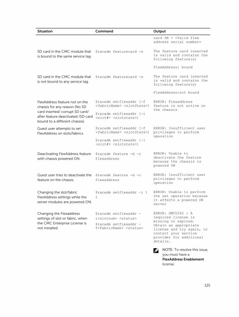
Situation Command Output
card SN = <Valid flex address serial number>
SD card in the CMC module that is bound to the same service tag.
$racadm featurecard -s The feature card inserted is valid and contains the following feature(s)
FlexAddress: bound
SD card in the CMC module that is not bound to any service tag.
$racadm featurecard -s The feature card inserted is valid and contains the following feature(s)
FlexAddress:not bound
FlexAddress feature not on the chassis for any reason (No SD card inserted/ corrupt SD card/ after feature deactivated /SD card bound to a different chassis).
$racadm setflexaddr [-f <fabricName> <slotState>]
$racadm setflexaddr [-i <slot#> <slotstate>]
ERROR: Flexaddress feature is not active on the chassis
Guest user attempts to set FlexAddress on slots/fabrics.
$racadm setflexaddr [-f <fabricName> <slotState>]
$racadm setflexaddr [-i <slot#> <slotstate>]
ERROR: Insufficient user privileges to perform operation
Deactivating FlexAddress feature with chassis powered ON.
$racadm feature -d -c flexaddress
ERROR: Unable to deactivate the feature because the chassis is powered ON
Guest user tries to deactivate the feature on the chassis.
$racadm feature -d -c flexaddress
ERROR: Insufficient user privileges to perform operation
Changing the slot/fabric FlexAddress settings while the server modules are powered ON.
$racadm setflexaddr -i 1 1
ERROR: Unable to perform the set operation because it affects a powered ON server
Changing the Flexaddress settings of slot or fabric, when the CMC Enterprise License is not installed.
$racadm setflexaddr -i<slotnum> <status>$racadm setflexaddr -f<FabricName> <status>
ERROR: SWC0242 : A required license is missing or expired. Obtain an appropriate license and try again, or contact your service provider for additional details.
NOTE: To resolve this issue, you must have a FlexAddress Enablement license.
125
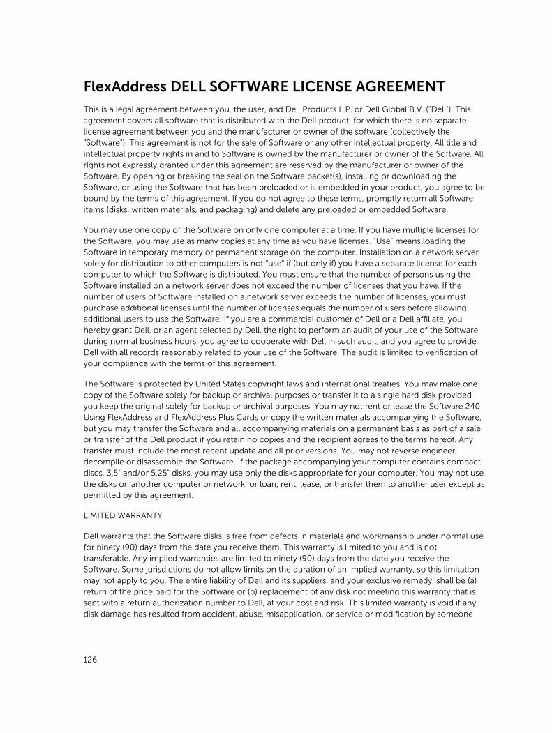
FlexAddress DELL SOFTWARE LICENSE AGREEMENT
This is a legal agreement between you, the user, and Dell Products L.P. or Dell Global B.V. ("Dell"). This agreement covers all software that is distributed with the Dell product, for which there is no separate license agreement between you and the manufacturer or owner of the software (collectively the "Software"). This agreement is not for the sale of Software or any other intellectual property. All title and intellectual property rights in and to Software is owned by the manufacturer or owner of the Software. All rights not expressly granted under this agreement are reserved by the manufacturer or owner of the Software. By opening or breaking the seal on the Software packet(s), installing or downloading the Software, or using the Software that has been preloaded or is embedded in your product, you agree to be bound by the terms of this agreement. If you do not agree to these terms, promptly return all Software items (disks, written materials, and packaging) and delete any preloaded or embedded Software.
You may use one copy of the Software on only one computer at a time. If you have multiple licenses for the Software, you may use as many copies at any time as you have licenses. "Use" means loading the Software in temporary memory or permanent storage on the computer. Installation on a network server solely for distribution to other computers is not "use" if (but only if) you have a separate license for each computer to which the Software is distributed. You must ensure that the number of persons using the Software installed on a network server does not exceed the number of licenses that you have. If the number of users of Software installed on a network server exceeds the number of licenses, you must purchase additional licenses until the number of licenses equals the number of users before allowing additional users to use the Software. If you are a commercial customer of Dell or a Dell affiliate, you hereby grant Dell, or an agent selected by Dell, the right to perform an audit of your use of the Software during normal business hours, you agree to cooperate with Dell in such audit, and you agree to provide Dell with all records reasonably related to your use of the Software. The audit is limited to verification of your compliance with the terms of this agreement.
The Software is protected by United States copyright laws and international treaties. You may make one copy of the Software solely for backup or archival purposes or transfer it to a single hard disk provided you keep the original solely for backup or archival purposes. You may not rent or lease the Software 240 Using FlexAddress and FlexAddress Plus Cards or copy the written materials accompanying the Software, but you may transfer the Software and all accompanying materials on a permanent basis as part of a sale or transfer of the Dell product if you retain no copies and the recipient agrees to the terms hereof. Any transfer must include the most recent update and all prior versions. You may not reverse engineer, decompile or disassemble the Software. If the package accompanying your computer contains compact discs, 3.5" and/or 5.25" disks, you may use only the disks appropriate for your computer. You may not use the disks on another computer or network, or loan, rent, lease, or transfer them to another user except as permitted by this agreement.
LIMITED WARRANTY
Dell warrants that the Software disks is free from defects in materials and workmanship under normal use for ninety (90) days from the date you receive them. This warranty is limited to you and is not transferable. Any implied warranties are limited to ninety (90) days from the date you receive the Software. Some jurisdictions do not allow limits on the duration of an implied warranty, so this limitation may not apply to you. The entire liability of Dell and its suppliers, and your exclusive remedy, shall be (a) return of the price paid for the Software or (b) replacement of any disk not meeting this warranty that is sent with a return authorization number to Dell, at your cost and risk. This limited warranty is void if any disk damage has resulted from accident, abuse, misapplication, or service or modification by someone
126

other than Dell. Any replacement disk is warranted for the remaining original warranty period or thirty (30) days, whichever is longer.
Dell does NOT warrant that the functions of the Software meets your requirements or that operation of the Software is uninterrupted or error free. You assume responsibility for selecting the Software to achieve your intended results and for the use and results obtained from the Software.
DELL, ON BEHALF OF ITSELF AND ITS SUPPLIERS, DISCLAIMS ALL OTHER WARRANTIES, EXPRESS OR IMPLIED, INCLUDING, BUT NOT LIMITED TO, IMPLIED WARRANTIES OF MERCHANTABILITY AND FITNESS FOR A PARTICULAR PURPOSE, FOR THE SOFTWARE AND ALL ACCOMPANYING WRITTEN MATERIALS. This limited warranty gives you specific legal rights; you may have others, which vary from jurisdiction to jurisdiction.
IN NO EVENT SHALL DELL OR ITS SUPPLIERS BE LIABLE FOR ANY DAMAGES WHATSOEVER (INCLUDING, WITHOUT LIMITATION, DAMAGES FOR LOSS OF BUSINESS PROFITS, BUSINESS INTERRUPTION, LOSS OF BUSINESS INFORMATION, OR OTHER PECUNIARY LOSS) ARISING OUT OF USE OR INABILITY TO USE THE SOFTWARE, EVEN IF ADVISED OF THE POSSIBILITY OF SUCH DAMAGES. Because some jurisdictions do not allow an exclusion or limitation of liability for consequential or incidental damages, the above limitation may not apply to you.
OPEN SOURCE SOFTWARE
A portion of this CD may contain open source software, which you can use under the terms and conditions of the specific license under which the open source software is distributed.
THIS OPEN SOURCE SOFTWARE IS DISTRIBUTED IN THE HOPE THAT IT WILL BE USEFUL, BUT IS PROVIDED "AS IS" WITHOUT ANY EXPRESSED OR IMPLIED WARRANTY; INCLUDING BUT NOT LIMITED TO THE IMPLIED WARRANTY OF MERCHANTABILITY OR FITNESS FOR A PARTICULAR PURPOSE. IN NO EVENT SHALL DELL, THE COPYRIGHT HOLDERS, OR THE CONTRIBUTORS BE LIABLE FOR ANY DIRECT, INDIRECT, INCIDENTAL, SPECIAL, EXEMPLARY, OR CONSEQUENTIAL DAMAGES (INCLUDING, BUT NOT LIMITED TO, PROCUREMENT OF SUBSTUTUTE GOODS OR SERVICES; LOSS OF USE, DATA, OR PROFITS; OR BUSINESS INTERRUPTION) HOWEVER CAUSED AND ON ANY THEORY OF LIABILTIY, WHETHER IN CONTRACT, STRICT LIABITLY, OR TORT (INCLUDING NEGLIGENCE OR OTHERWISE) ARISING IN ANY WAY OUT OF THE USE OF THIS SOFTWARE, EVEN IF ADVISED OF THE POSSIBILTIY OF SUCH DAMAGE.
U.S. GOVERNMENT RESTRICTED RIGHTS
The software and documentation are "commercial items" as that term is defined at 48 C.F.R. 2.101, consisting of "commercial computer software" and "commercial computer software documentation" as such terms are used in 48 C.F.R. 12.212. Consistent with 48 C.F.R. 12.212 and 48 C.F.R. 227.7202-1 through 227.7202-4, all U.S. Government end users acquire the software and documentation with only those rights set forth herein.
Contractor/manufacturer is Dell Products, L.P., One Dell Way, Round Rock, Texas 78682.
GENERAL
This license is effective until terminated. It terminates upon the conditions set forth above or if you fail to comply with any of its terms. Upon termination, you agree that the Software and accompanying materials, and all copies thereof, is destroyed. This agreement is governed by the laws of the State of
127
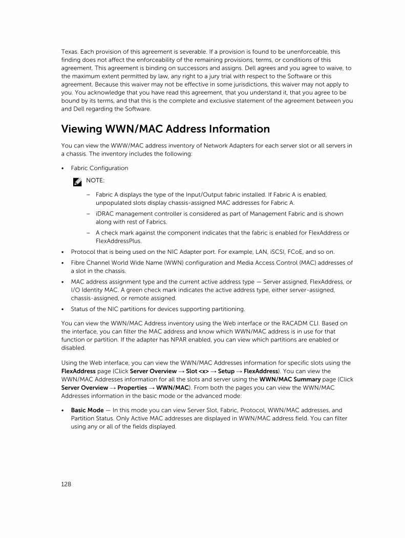
Texas. Each provision of this agreement is severable. If a provision is found to be unenforceable, this finding does not affect the enforceability of the remaining provisions, terms, or conditions of this agreement. This agreement is binding on successors and assigns. Dell agrees and you agree to waive, to the maximum extent permitted by law, any right to a jury trial with respect to the Software or this agreement. Because this waiver may not be effective in some jurisdictions, this waiver may not apply to you. You acknowledge that you have read this agreement, that you understand it, that you agree to be bound by its terms, and that this is the complete and exclusive statement of the agreement between you and Dell regarding the Software.
Viewing WWN/MAC Address Information
You can view the WWW/MAC address inventory of Network Adapters for each server slot or all servers in a chassis. The inventory includes the following:
• Fabric Configuration
NOTE:
– Fabric A displays the type of the Input/Output fabric installed. If Fabric A is enabled, unpopulated slots display chassis-assigned MAC addresses for Fabric A.
– iDRAC management controller is considered as part of Management Fabric and is shown along with rest of Fabrics.
– A check mark against the component indicates that the fabric is enabled for FlexAddress or FlexAddressPlus.
• Protocol that is being used on the NIC Adapter port. For example, LAN, iSCSI, FCoE, and so on.
• Fibre Channel World Wide Name (WWN) configuration and Media Access Control (MAC) addresses of a slot in the chassis.
• MAC address assignment type and the current active address type — Server assigned, FlexAddress, or I/O Identity MAC. A green check mark indicates the active address type, either server-assigned, chassis-assigned, or remote assigned.
• Status of the NIC partitions for devices supporting partitioning.
You can view the WWN/MAC Address inventory using the Web interface or the RACADM CLI. Based on the interface, you can filter the MAC address and know which WWN/MAC address is in use for that function or partition. If the adapter has NPAR enabled, you can view which partitions are enabled or disabled.
Using the Web interface, you can view the WWN/MAC Addresses information for specific slots using the
FlexAddress page (Click Server Overview → Slot <x> → Setup → FlexAddress). You can view the WWN/MAC Addresses information for all the slots and server using the WWN/MAC Summary page (Click
Server Overview → Properties → WWN/MAC). From both the pages you can view the WWN/MAC Addresses information in the basic mode or the advanced mode:
• Basic Mode — In this mode you can view Server Slot, Fabric, Protocol, WWN/MAC addresses, and Partition Status. Only Active MAC addresses are displayed in WWN/MAC address field. You can filter using any or all of the fields displayed.
128
• Advanced Mode — In this mode you can view all the fields displayed in the basic mode and all the MAC types (Server Assigned, Flex Address, and IO Identity). You can filter using any or all of the fields displayed.
In both the Basic mode and the Advanced mode, the WWN/MAC Addresses information is displayed in a
collapsed form. Click the against a slot or click Expand/Collapse All to view the information for a specific slot or all the slots.
You can also export the WWN/MAC Addresses information for all the servers in the chassis to a local folder.
For information about the fields, see the CMC for Dell PowerEdge FX2/FX2s Online Help.
Viewing Basic WWN/MAC Address Information Using Web InterfaceTo view WWN/MAC Address information for each server slot or all servers in a chassis, in the basic mode:
1. Click Server Overview → Properties → WWN/MAC
The WWN/MAC Summary page displays the WWN/MAC Address Information.
Alternatively, click Server Overview → Slot <x> → Setup → FlexAddress to view the WWN/MAC Address information for a specific server slot. The FlexAddress page is displayed.
2. In the WWN/MAC Addresses table, click Export to save the WWN/MAC addresses locally.
3. Click the against a slot or click Expand/Collapse All to expand or collapse the attributes listed for a specific slot or all the slots in the WWN/MAC Addresses table.
4. From the View drop-down menu, select Basic, to view the WWN/MAC Addresses attributes in tree view.
5. From the Server Slot drop-down menu, select All Servers or a specific Slot to view the WWN/MAC Addresses attributes for all servers or servers in specific slots only respectively.
6. From the Fabric drop-down menu, select one of the fabric types to view details for all or specific type of management or I/O fabric associated with the servers.
7. From the Protocol drop-down menu, select All Protocols or one of the listed network protocols to view all the MACSsor the MACs associated with the selected protocol.
8. In the WWN/MAC Addresses field, to filter a slot associated with the specific MAC address, enter the exact MAC address. Alternately, partially enter the MAC address entries to view the associated slots. For example, enter 4A to view the slots with MAC addresses that contain 4A.
9. From the Partition Status drop-down menu, select the status of the partitions to display servers with the selected partition status.
If a particular partition is disabled, the row displaying the partition is greyed out.
For information about the fields, see the CMC for Dell PowerEdge FX2/FX2s Online Help.
Viewing Advanced WWN/MAC Address Information Using Web InterfaceTo view WWN/MAC Address Information for each server slot or all servers in a chassis, in the advanced mode:
1. Click Server Overview → Properties → WWN/MAC
129
The WWN/MAC Summary page displays the WWN/MAC Address Information.
2. From the View drop-down menu, select Advanced, to view the WWN/MAC Addresses attributes in detailed view.
In the WWN/MAC Addresses table displays Server Slot, Fabric, Protocol, WWN/MAC addresses, MAC address assignment type — Server assigned, FlexAddress, or I/O Identity MAC, and Partition Status. A green check mark indicates the active address type, either server-assigned, chassis-assigned, or remote assigned. MAC. If a server does not have the FlexAddress or I/O Identity enabled, then the status for FlexAddress (Chassis-Assigned) or I/O Identity (Remote-Assigned) is displayed as Not Enabled.
3. In the WWN/MAC Addresses table, click Export to save the WWN/MAC addresses locally.
4. Click the against a slot or click Expand/Collapse All to expand or collapse the attributes listed for a specific slot or all the slots in the WWN/MAC Addresses table.
5. From the Server Slot drop-down menu, select All Servers or a specific Slot to view the WWN/MAC Addresses attributes for all servers or servers in specific slots only respectively.
6. From the Fabric drop-down menu, select one of the fabric types to view details for all or specific type of management or I/O fabric associated with the servers.
7. From the Protocol drop-down menu, select All Protocols or one of the listed network protocols to view all the MACS or the MACs associated with the selected protocol.
8. In the WWN/MAC Addresses field, enter the MAC address to view only the slots associated with the specific MAC address. Alternately, partially enter the MAC address entries to view the associated slots. For example, enter 4A to view the slots with MAC addresses that contain 4A.
9. From the Partition Status drop-down menu, select the status of the partitions to display servers with the selected partition status.
If a particular partition is disabled, the status is displayed as Disabled and the row displaying the partition is greyed out.
For information about the fields, see the CMC for Dell PowerEdge FX2/FX2s Online Help.
Viewing WWN/MAC Address Information Using RACADM
To view WWNn/MAC address information for all servers or specific servers using RACADM, use the getflexaddr and getmacaddress subcommands.
To display Flexaddress for the entire chassis, use the following RACADM command:
racadm getflexaddr
To display Flexaddress status for a particular slot, use the following RACADM command:
racadm getflexaddr [-i <slot#>]where <slot #> is a value from 1 to 4.
To display the NDC or LOM MAC address, use the following RACADM command:
racadm getmacaddress
To display the MAC address for chassis, use the following RACADM command:
racadm getmacaddress -m chassis
To display the iSCSI MAC addresses for all servers, use the following RACADM command:
racadm getmacaddress -t iscsi
130
To display the iSCSI MAC for a specific server, use the following RACADM command:
racadm getmacaddress [-m <module> [-x]] [-t iscsi]
To display the user-defined MAC and WWN address, use the following RACADM command:
racadm getmacaddress -c io-identity racadm getmacaddress -c io-identity -m server -2
To display Ethernet and iSCSI MACS addresses of all LOMs or mezzanine cards, use the following RACADM command:
racadm getmacaddress -a
To display the console assigned MAC/WWN of all LOMs or mezzanine cards, use the following RACADM command:
racadm getmacaddress -c all
To display the chassis assigned WWN/MAC address, use the following RACADM command:
racadm getmacaddress -c flexaddress
To display the MAC/WWN addresses for all LOMs or mezzanine cards, use the following RACADM command:
racadm getmacaddress -c factory
For more information on the getflexaddr and getmacaddress subcommand, see the Dell Chassis Management Controller for PowerEdge FX2/FX2s RACADM Command Line Reference Guide.
131
13Managing FabricsThe chassis supports two fabric types: Fabric A1 and Fabric A2, which are used by the two I/O Modules, and are always connected to the on-board Ethernet adapters of the servers.
NOTE: In the PowerEdge FX2s chassis, fabrics B and C are the PCIe connection to the PCIe Extension cards.
Following IO Modules are supported:
• 1GbE pass-through
• 10GbE pass-through
• I/O Aggregator (available in PowerEdge FX2/FX2s)
Both the Fabrics support only Ethernet. Each server IO adapter ( LOM) can have either two or four ports depending on the capability. The mezzanine card slots are occupied by PCIe extension cards that are connected to PCIe cards (and not to IO modules).
NOTE: In the CMC CLI, the IOM is referred to by the convention, switch.
Monitoring IOM HealthFor information about monitoring IOM health, see Viewing Information and Health Status of the IOM.
Configuring Network Settings for IOM
You can specify the network settings for the interface used to manage the IOM. For Ethernet switches, the out-of-band management port (IP address) is configured. The in-band management port (that is, VLAN1) is not configured using this interface.
Before configuring the network settings for the IOM, make sure the IOM is turned on.
To configure the network setting of IOM in Group A, you must have the Fabric A Administrator privileges.
NOTE: For Ethernet switches, the in-band (VLAN1) and out-of-band management IP addresses cannot be the same, or cannot be on the same network. This results in the out-of-band IP address in being not set. See the IOM documentation for the default in-band management IP address.
NOTE: Do not configure I/O module network settings for Ethernet pass-through and Infiniband switches.
132
Configuring Network Settings for IOM Using CMC Web Interface
To configure the network settings for I/O Module:
1. In the left pane, click Chassis Overview, click I/O Module Overview, and then click Setup. Alternatively, to configure the network settings of the available I/O modules that is A1 and A2, click A1 Gigabit Ethernet or A2 Gigabit Ethernet, and then click Setup.
On the Configure I/O Module Network Settings page, type appropriate data, and then click Apply.
2. If allowed, type the root password, SNMP RO Community string, and Syslog Server IP Address for the IOM. For more information about the field descriptions, see the Online Help.
NOTE: The IP address set on the IOM from CMC is not saved to the permanent startup configuration of the switch. To permanently save the IP address configuration, you must run the connect switch command, or racadm connect switch RACADM command, or use a
direct interface to the IOM GUI to save this address to the startup configuration file.
3. Click Apply.
The network settings are configured for the IOM.
NOTE: If allowed, you can reset the VLANs, network properties, and IO ports to its default configuration values.
Configuring Network Settings for IOM Using RACADM
To configure the network settings for an IOM by using RACADM, set the date and time. See the deploy command section in the Dell Chassis Management Controller for PowerEdge FX2/FX2s RACADM Command Line Reference Guide.
You can set the user name, password, and SNMP string for the IOM using the RACADM deploy command:
racadm deploy -m switch -u <username> -p <password>racadm deploy -m switch -u -p <password> -v SNMPv2 <snmpCommunityString> roracadm deploy -a [server|switch] -u <username> -p <password>
Viewing I/O Module Uplink and Downlink Status Using Web Interface
NOTE: This feature is available only in PowerEdge FX2/FX2s.
You can view the uplink and downlink status information for Dell PowerEdge M I/O Aggregator using the CMC Web interface. To do this:
1. Go to Chassis Overview → I/O Module Overview.
All the IOMs (1–2) appear in the expanded list.
2. Click the IOM (slot) you want to view.
The I/O Module Status page specific to the IOM slot is displayed. The I/O Module Uplink Status and I/O Module Downlink Status tables are displayed. These tables display information about the downlink ports (1-8) and uplink ports (9-12). For more information, see the CMC for Dell PowerEdge FX2/FX2s Online Help.
133
Viewing I/O Module FCoE Session Information Using Web InterfaceYou can view the FCoE session information for Dell PowerEdge M I/O Aggregator using the CMC web interface. To do this:
1. Go to Chassis Overview → I/O Module Overview.
All the IOMs (1–6) appear in the expanded list.
2. Click the IOM (slot) you want to view. Click Properties → FCoE.
The FCoE I/O Module page specific to the IOM slot is displayed.
3. In the Select Port drop-down, select the required port number for the selected IOM and click Show Sessions. The selected option retrieves the FCoE session information for the switch, and present it to the user as a table.
The FCoE Session Information section displays the FCoE session information for the switch.
NOTE: The I/O Aggregator also displays the active FCoE sessions when the switch is using the protocol.
Resetting IOM to Factory Default SettingsYou can reset IOM to the factory default settings using the Deploy I/O Modules page.
NOTE: This feature is supported on PowerEdge M I/O Aggregator IOM only. Other IOMs including MXL 10/40GbE are not supported.
To reset the selected IOMs to factory default settings using the CMC Web interface:
1. In the system tree, go to I/O Module Overview and click Setup or expand I/O Module Overview in the system tree, select the IOM, and click Setup.
The Deploy I/O Modules page displays the IOM(s) that are powered on.
2. For the required IOM(s), click Reset.
A warning message is displayed.
3. Click OK to continue.
Updating IOM Software Using CMC Web InterfaceYou can update the IOM software by selecting the required software image from a specified location. You can also rollback to an earlier software version.
NOTE: This feature is supported only on Dell PowerEdge I/O Aggregator.
To update the IOM Infrastructure device software, in the CMC Web interface:
1. Go to Chassis Overview → I/O Module Overview → Update.
The IOM Firmware Update page is displayed. Alternatively, go to any of the following
• Chassis Overview → Update.
• Chassis Overview → Chassis Controller → Update.
134

The Firmware Update page is displayed, which provides a link to access the IOM Firmware and Software page.
2. In the IOM Firmware Update page, in the Firmware section, select the check box in the Update column for the IOM you want to update the software and click Apply Firmware Update. Alternatively, to rollback to the earlier versions of the software, select the check box in the Rollback column.
3. Select the software image for the software update, using the Browse option. The name of Software image gets displayed in the IOM Software Location field.
The Update Status section provides software update or rollback status information. A status indicator displays on the page while the image file uploads. File transfer time varies based on connection speed. When the internal update process begins, the page automatically refreshes and the Firmware update timer is displayed.
NOTE: Do not click the Refresh icon or navigate to another page during the file transfer.
NOTE: The file transfer timer is not displayed when updating IOMINF firmware.
NOTE: The FTOS or IOM software version is displayed in the format X-Y(A-B). For example, 8-3(1-4). If the Rollback Version of the FTOS image is an old image which uses the old version string format 8-3-1-4, then the Current Version is displayed as 8-3(1-4).
135
14Using VLAN ManagerYou can assign or view the VLAN settings on the IOMs by using the VLAN Manager option.
NOTE: This feature is supported only on Dell PowerEdge I/O Aggregator.
Assigning VLAN to IOM
Virtual LAN (VLAN) for IOMs allows you to separate users into individual network segments for security and other reasons. By using VLANs you can isolate the networks for individual users on a 32 port switch. You can associate selected ports on a switch with selected VLAN and treat these ports as a separate switch.
CMC Web Interface allows you to configure the in-band management ports (VLAN) on the IOMs.
To assign a VLAN to an IOM, go to Chassis Overview → I/O Module Overview → Setup → VLAN Manager.
In the VLAN Assignment section, select the I/O Module and choose the type of configuration. Also specify the port range and the slot.
Change or edit the VLANs by selecting from the list in the drop-down menu.
Configuring VLAN settings on IOMs Using CMC Web Interface To configure the VLAN settings on IOM(s) using the CMC Web interface:
1. Go to I/O Module Overview and click Setup VLAN Manager.
The VLAN Manager page displays the IOM(s) that are turned on and the available ports.
2. In the Select I/O Module section, select the configuration type from the drop down list, and then select the required IOM(s).
3. In the Specify Port Range section, select the range of fabric ports to be assigned to the selected IOM(s).
4. Select the Select or Deselect All option to apply the changes to all or no IOMs.
or
Select the check box for the specific slots to select the required IOMs.
5. In the Edit VLANs section, enter the VLAN IDs for the IOMs. Enter VLAN IDs in the range 1-4094. VLAN IDs can be entered as a range or separated by a comma.
6. Select one of the following options from the drop-down menu as required:
136

• Add Tagged VLANs
• Remove VLANs
• Update untagged VLANs
• Reset to all VLANs
• Show VLANs
7. Click Save to save the new settings made to the VLAN Manager page.
NOTE: The Summary VLANs of All Ports section displays information about the IOMs present in the Chassis and the assigned VLANs. Click Save to save a csv file of the summary of the current VLAN settings.
NOTE: The CMC Managed VLANs section displays the summary of all VLANs assigned to the IOMs.
8. Click Apply.
The network settings are configured for the IOM(s).
Viewing the VLAN settings on IOMs Using CMC Web InterfaceTo view the VLAN settings on IOM(s) using the CMC Web interface:
1. Go to I/O Module Overview, and click Setup → VLAN Manager.
The VLAN Manager page is displayed. The Summary VLANs of All Ports section displays information about the current VLAN settings for the IOMs.
2. Click Save to save the VLAN settings to a file.
Viewing the Current VLAN Settings on IOMs Using CMC Web InterfaceTo view the current VLAN settings on IOMs using the CMC Web Interface:
1. Go to I/O Module Overview, and click Setup → VLAN Manager.
The VLAN Manager page is displayed.
2. In the Edit VLANs section, select Show VLANs in the drop down list and click Apply.
An Operation Successful message is displayed. The current VLAN settings that are assigned to the IOMs are displayed in the VLAN Assignment Summary field.
Removing VLANs for IOMs Using CMC Web InterfaceTo remove VLANs from IOM(s) using the CMC Web interface:
1. Go to I/O Module Overview, and click Setup → VLAN Manager.
The VLAN Manager page is displayed.
2. In the Select I/O Module section, select the required IOMs.
3. In the Edit VLANs section, select Remove VLANs in the drop down list and click Apply.
The VLANs assigned to the selected IOMs are removed.
137
An Operation Successful message is displayed. The current VLAN settings that are assigned to the IOMs are displayed in the VLAN Assignment Summary field.
Updating Untagged VLANs for IOMs Using CMC Web InterfaceTo update untagged VLANs for IOM(s) using the CMC Web interface:
NOTE: The untagged VLANs cannot be set to a VLAN ID that is already tagged.
1. Go to, I/O Module Overview , and click Setup → VLAN Manager.
The VLAN Manager page is displayed.
2. In the Select I/O Module section, select the required IOMs.
3. In the Specify Port Range section, select the range of fabric ports to be assigned to the selected IOM(s).
4. Select the Select or Deselect All option to apply the changes to all or no IOMs.
or
Select the check box against the specific slots to select the required IOMs.
5. In the Edit VLANs section, select Update the Untagged VLANs in the drop down list and click Apply.
A warning message is displayed that the configurations of the existing untagged VLAN will be overwritten with the configurations of the newly assigned untagged VLAN.
6. Click OK to confirm.
The untagged VLANs are updated with the configurations of the newly assigned untagged VLAN.
An Operation Successful message is displayed. The current VLAN settings that are assigned to the IOMs are displayed in the VLAN Assignment Summary field.
Resetting VLANs for IOMs Using CMC Web InterfaceTo reset VLANs for IOM(s) to default configurations using the CMC Web interface:
1. Go to I/O Module Overview, and click Setup → VLAN Manager.
The VLAN Manager page is displayed.
2. In the Select I/O Module section, select the required IOMs.
3. In the Edit VLANs section, select Reset VLANs in the drop down list and click Apply.
A warning message is displayed indicating that the configurations of the existing VLANs will be overwritten with the default configurations.
4. Click OK to confirm.
The VLANs are assigned to the selected IOMs according to the default configurations.
An Operation Successful message is displayed. The current VLAN settings that are assigned to the IOMs are displayed in the VLAN Assignment Summary field.
138

15Managing and Monitoring PowerThe PowerEdge FX2/FX2s chassis is the most power-efficient server enclosure. It is designed to include highly efficient power supplies and fans, has an optimized layout for the air to flow more easily through the system, and contains power-optimized components throughout the enclosure. The optimized hardware design is coupled with sophisticated power management capabilities that are built into the Chassis Management Controller (CMC), power supplies, and iDRAC to allow you to further enhance power-efficient server environment.
Power management in PowerEdge FX2/FX2s is relatively different from PowerEdge VRTX. One major change in the power management technique is the use of a Closed Loop System Throttle (CLST) to maintain the desired chassis power cap. The purpose of using this technique is that, it has a better control, also allows the chassis to make full use of the available PSU.
The Power Management features of PowerEdge FX2/FX2s help administrators configure the enclosure to reduce power consumption and to adjust the power as required specific to the environment.
The PowerEdge FX2/FX2s enclosure consumes AC power and distributes the load across the active power supply unit (PSU). The system can deliver up to 3371 Watts of AC power that is allocated to server modules and the associated enclosure infrastructure. However, this capacity varies based on the power redundancy policy that you select.
The PowerEdge FX2/FX2s enclosure can be configured for any of the three redundancy policies that affect PSU behavior and determine how chassis Redundancy state is reported to administrators.
You can also control Power management through OpenManage Power Center (OMPC). When OMPC controls power externally, CMC continues to maintain:
• Redundancy policy
• Remote power logging
OMPC then manages:
• Server power
• System Input Power Capacity
NOTE: Actual power delivery is based on the configuration and workload.
You can use the CMC web interface or RACADM to manage and configure power controls on CMC:
• View the status for the chassis, servers, and PSUs.
• Configure power budget and redundancy policy for the chassis.
• Execute power control operations (turn on, turn off, system reset, power-cycle) for the chassis.
139
Redundancy Policies
Redundancy policy is a configurable set of properties that determine how CMC manages power to the chassis. The following redundancy policies are configurable:
• Grid Redundancy
• No Redundancy
• Redundancy Alerting Only
Grid Redundancy Policy
The purpose of the Grid Redundancy policy is to enable an enclosure system to operate in a mode in which it can tolerate AC power failures. These failures may originate in the AC power grid, the cabling and delivery, or a PSU itself. When you configure a system for Grid Redundancy, connect PSUs 1 and 2 to separate power grids.
In this mode the CMC ensures power usage is maintained such that the system will continue to operate with no degradation if there is a failure of either the grid or a single PSU. Server power-on is limited to the available power of a single PSU. If at any time redundancy cannot be maintained (such as if a PSU is removed or fails) alerts are triggered, the chassis health becomes Critical.
No Redundancy Policy
In this mode all the power of both PSUs is available and used, but there is no assurance that a PSU or grid failure will not impact system operation. The redundancy status of the chassis is always No Redundancy.
Redundancy Alerting Only Policy
The Redundancy Alerting Only policy permits server power-on to use the capacity of both PSUs, while alerting redundancy loss based on actual conditions. Redundancy loss is alerted if a PSU is removed or fails, or if actual power consumption exceeds the capabilities of a single PSU. This is the default policy.
PSU Failures
PSU failures of any type are always alerted, regardless of the the selected redundancy policy.
Default Redundancy Configuration
Redundancy Alerting Only is the default redundancy configuration for a chassis and two PSUs.
Multi-node Sled Adaptation
The PowerEdge FM120x4 is a multi-node, half-width Sled that can accommodate four servers with the associated iDRAC with independent processors. It is designed for optimal power efficiency and the processors cannot be removed. The processors in PowerEdge FM120 share a common power infrastructure, for example, a single power and temperature sensors for the entire Sled.
140

Chassis Power Limit Monitoring
Open Manage Power Center (OMPC) can be used to monitor and control power consumption of the machines in a data center. PowerEdge FX2/FX2s enables OMPC by providing a provision to set the power cap for the chassis, and bounds to guide the setting of the power cap. The lower and upper bounds for the power cap is set by the CMC and cannot be configured.
NOTE: The lower bound is the minimum power needed to operate the chassis given the current configuration. The upper bound reflects the maximum power available in the current redundancy policy.
Viewing Power Consumption Status
CMC provides the actual input power consumption for the entire system.
Viewing Power Consumption Status Using CMC Web Interface
In the left pane, click Chassis Overview → Power → Power Monitoring. The Power Monitoring page displays the power health, system power status, real-time power statistics, and real-time energy statistics. For more information, see the Online Help.
NOTE: You can also view the power redundancy status under Power Supplies.
Viewing Power Consumption Status Using RACADM
To view power consumption status using RACADM:
Open a serial/Telnet/SSH text console to CMC, log in, and type:
racadm getpminfo
Viewing Power Budget Status Using CMC Web InterfaceTo view power budget status using CMC Web interface, in the left pane go to Chassis Overview and click Power → Budget Status. The Power Budget Status page displays the system power policy configuration with the attributes System Input Power cap, Redundancy Policy, power budget details with the attributes System Input Max Power Capacity, Input Redundancy Reserve, Power Available for Server Power-on, and chassis power supply with the power supply unit details. For more information, see the CMC for Dell PowerEdge FX2/FX2s Online Help.
Viewing Power Budget Status Using RACADMOpen a serial/Telnet/SSH text console to CMC, log in, and type:
racadm getpbinfoFor more information about getpbinfo, including output details, see the getpbinfo command section in the Dell Chassis Management Controller for PowerEdge FX2/FX2s RACADM Command Line Reference Guide.
141

Redundancy Status and Overall Power Health
The redundancy status is a factor in determining the overall power health. When the power redundancy policy is set, for example, to grid redundancy and the redundancy status indicates that the system is operating with redundancy, the overall power health is typically OK. However, if the conditions for operating with grid redundancy cannot be met, the redundancy status is No, and the overall power health is Critical. This is because the system is not able to operate in accordance with the configured redundancy policy.
NOTE: CMC does not perform a pre-check of these conditions when you change the redundancy policy to or from grid redundancy. So, configuring the redundancy policy may immediately result in redundancy lost or a regained condition.
Power Management After PSU Failure
In the event of a PSU failure or removal, the power supplied to servers may be reduced. In extreme cases servers could be powered off in an attempt to sustain operation. Configuring and maintaining Grid Redundancy avoids any impact to servers for a single PSU failure.
Power Supply and Redundancy Policy Changes in System Event Log
Changes in the power supply state and power redundancy policy are recorded as events. Events related to the power supply that record entries in the system event log (SEL) are power supply insertion and removal, power supply input insertion and removal, and power supply output assertion and de-assertion.
The following table lists the SEL entries that are related to power supply changes:
Table 16. SEL Events for Power Supply Changes
Power Supply Event System Event Log (SEL) Entry
Insertion Power supply is present.
Removal Power supply is absent.
AC input received The power input for power supply has been restored.
AC input lost The power input for power supply is lost.
DC output produced Power supply is operating normally.
DC output lost Power supply failed.
Events related to changes in the power redundancy status that record entries in the SEL are redundancy loss and redundancy regain for the enclosure that is configured for the Grid Redundancy power policy or Redundancy Alerting Only power policy. The following table lists the SEL entries that are related to power redundancy policy changes.
Power Policy Event System Event Log (SEL) Entry
Redundancy lost Power supply redundancy is lost.
Redundancy regained The power supplies are redundant.
142

Configuring Power Budget and Redundancy
You can configure the power budget, redundancy, and dynamic power of the entire chassis (chassis, servers, I/O module, CMC, PCIe, and chassis infrastructure). The power management service optimizes power consumption and reallocates power to different modules on the basis of requirement.
You can configure the following:
• System Input Power Cap
• Redundancy Policy
• Disable Chassis Power Button
• Max Power Conservation Mode
• Remote Power Logging
• Remote Power Logging Interval
Power Conservation and Power Budget
If the power usage exceeds the System Input Power Cap, the power supplied to the servers by the PSU is reduced to maintain the nominal level.
Configuring Power Budget and Redundancy Using CMC Web Interface
NOTE: To perform power management actions, you must have the Chassis Configuration Administrator privilege.
To configure power budget:
1. In the left pane, click Chassis Overview → Power → Configuration.
2. On the Budget/Redundancy Configuration page, select any or all of the following properties as appropriate. For information about the field descriptions, see the Online Help.
• Redundancy Policy
• Disable Chassis Power Button
• Max Power Conservation Mode
3. Click Apply to save the changes.
Configuring Power Budget and Redundancy Using RACADM
NOTE: To perform power management actions, you must have the Chassis Configuration Administrator privilege.
To enable and set the redundancy policy:
1. Open a serial/Telnet/SSH text console to CMC and log in.
2. Set properties as needed:
• To select a redundancy policy, type:
racadm config -g cfgChassisPower -ocfgChassisRedundancyPolicy <value>where <value> is 0 (No Redundancy), 1 (Grid Redundancy), and 3 (Redundancy Alerting Only). The default value is 3.
143

For example, the following command sets the redundancy policy to :
racadm config -g cfgChassisPower -ocfgChassisRedundancyPolicy 1
• To set the power budget value, type:
racadm config -g cfgChassisPower -ocfgChassisPowerCap <value>where <value> is a number between the Current runtime Chassis Burden and 3371, representing the maximum power limit in Watt. The default is 3371.
For example, the following command sets the maximum power budget to 3371 Watt:
racadm config -g cfgChassisPower -ocfgChassisPowerCap 3371
• To view the upper bound and the lower bound, type:
racadm getconfig -g cfgchassispower -o cfgchassispowercap <lower,upper> boundwhere <lower, upper> is the lower bound and the upper bound limit.
racadm config -g cfgChassisPower -ocfgChassisPowerCap 3000
• To enable the maximum power consumption mode, type:
racadm config -g cfgChassisPower -ocfgChassisMaxPowerConservationMode 1
• To restore normal operation, type:
racadm config -g cfgChassisPower -ocfgChassisMaxPowerConservationMode 0
• To enable the power remote logging feature, enter the following command:
racadm config -g cfgRemoteHosts -ocfgRhostsSyslogPowerLoggingEnabled 1
• To specify the desired logging interval, enter the following command:
racadm config -g cfgRemoteHosts -ocfgRhostsSyslogPowerLoggingInterval nwhere n is 1-1440 minutes.
• To determine if the power remote logging feature is enabled, enter the following command:
racadm getconfig -g cfgRemoteHosts -ocfgRhostsSyslogPowerLoggingEnabled
• To determine the power remote logging interval, enter the following command:
racadm getconfig -g cfgRemoteHosts -ocfgRhostsSyslogPowerLoggingIntervalThe power remote logging feature is dependent on previously configured remote syslog hosts having been . Logging to one or more remote syslog hosts must be enabled, otherwise power consumption is logged. This can be done either through the web GUI or the RACADM CLI. For more information, see the remote syslog configuration instructions.
• To restore CMC power management, type:
racadm config -g cfgChassisPower -ocfgChassisServerBasedPowerMgmtMode 0
For information about RACADM commands for chassis power, see the config, getconfig, getpbinfo, and cfgChassisPower sections in the Dell Chassis Management Controller for PowerEdge FX2/FX2s RACADM Command Line Reference Guide.
144
Executing Power Control Operations
You can execute the following power control operation for the chassis, servers, and IOM.
NOTE: Power control operations affect the entire chassis.
Executing Power Control Operations on the Chassis
CMC enables you to remotely perform several power management actions, such as an orderly shutdown on the entire chassis (chassis, servers, IOM, and PSUs).
Executing Power Control Operations on the Chassis Using Web Interface
To execute power control operations on the chassis using the CMC web interface:
1. In the left pane, click Chassis Overview → Power → Control.
The Chassis Power Control page is displayed.
2. Select one of the following power control operations.
For information about each option, see the Online Help.
• Power On System
• Power Off System
• Power Cycle System (cold boot)
• Reset CMC (warm boot)
• Non-Graceful Shutdown
3. Click Apply.
A dialog box appears asking you for a confirmation.
4. Click OK to perform the power management action (for example, cause the system to reset).
Executing Power Control Operations on the Chassis Using RACADM
Open a serial/Telnet/SSH text console to CMC, log in, and type:
racadm chassisaction -m chassis <action>where <action> is powerup, powerdown, powercycle, nongraceshutdown, or reset.
Executing Power Control Operations for Multiple Servers Using CMC Web Interface
To execute power control operation for multiple servers using the Web interface:
1. In the left pane, click Server Overview → Power.
The Power Control page is displayed.
2. In the Operations column, from the drop-down menu, select one of the following power control operations for the required servers:
• No Operation
• Graceful Shutdown
• Power On Server
• Power Off Server
• Reset Server (warm boot)
145
• Power Cycle Server (cold boot)
For information about the options, see the CMC for Dell PowerEdge FX2/FX2s Online Help.
3. Click Apply.
A dialog box appears requesting for confirmation.
4. Click OK to perform the power management action (for example, reset the server).
Executing Power Control Operations on the IOM
You can remotely reset or turn on an IOM.
NOTE: To perform power management actions, you must have the Chassis Control Administrator privilege.
Executing Power Control Operations on IOM Using CMC Web Interface
To execute power control operations on the I/O Module:
1. In the left pane, click Chassis Overview → I/O Module Overview → Power.
2. On the Power Control page, for the IOM, from the drop-down menu, select the operation you want to execute (power cycle).
3. Click Apply.
Executing Power Control Operations on the IOM Using RACADM
To execute power control operations on the IOM using RACADM, open a serial/Telnet/SSH text console to CMC, log in, and type:
racadm chassisaction -m switch <action>where <action> indicates the operation you want to execute: power cycle.
For information about RACADM commands, see the Dell Chassis Management Controller for PowerEdge FX2/FX2s RACADM Command Line Reference Guide. available at dell.com/support/manuals.
Configuring Sled Power Button
You can configure the Sled Power Button to disable, so that when you press the Sled power button, it has
no effect. To configure the Sled Power Button, go to Chassis Overview → Server Overview → Power → Control.
Under the Property section, select the check box to disable or clear the check box to enable.
NOTE: This setting is applicable only to multi-node Sleds present in the chassis. Other Sleds are not affected.
146
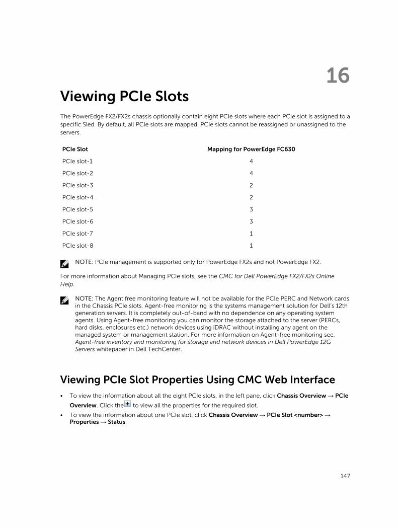
16Viewing PCIe SlotsThe PowerEdge FX2/FX2s chassis optionally contain eight PCIe slots where each PCIe slot is assigned to a specific Sled. By default, all PCIe slots are mapped. PCIe slots cannot be reassigned or unassigned to the servers.
PCIe Slot Mapping for PowerEdge FC630
PCIe slot-1 4
PCIe slot-2 4
PCIe slot-3 2
PCIe slot-4 2
PCIe slot-5 3
PCIe slot-6 3
PCIe slot-7 1
PCIe slot-8 1
NOTE: PCIe management is supported only for PowerEdge FX2s and not PowerEdge FX2.
For more information about Managing PCIe slots, see the CMC for Dell PowerEdge FX2/FX2s Online Help.
NOTE: The Agent free monitoring feature will not be available for the PCIe PERC and Network cards in the Chassis PCIe slots. Agent-free monitoring is the systems management solution for Dell’s 12th generation servers. It is completely out-of-band with no dependence on any operating system agents. Using Agent-free monitoring you can monitor the storage attached to the server (PERCs, hard disks, enclosures etc.) network devices using iDRAC without installing any agent on the managed system or management station. For more information on Agent-free monitoring see, Agent-free inventory and monitoring for storage and network devices in Dell PowerEdge 12G Servers whitepaper in Dell TechCenter.
Viewing PCIe Slot Properties Using CMC Web Interface• To view the information about all the eight PCIe slots, in the left pane, click Chassis Overview → PCIe
Overview. Click the to view all the properties for the required slot.
• To view the information about one PCIe slot, click Chassis Overview → PCIe Slot <number> → Properties → Status.
147

Viewing PCIe Slot Properties Using RACADM
You can view a PCIe slot assignment to a server by using the RACADM commands. Some of the commands are given here. For more information about the RACADM commands, see theDell Chassis Management Controller for PowerEdge FX2/FX2s RACADM Command Line Reference Guide available at dell.com/support/Manuals.
NOTE: The PCIe card name will be displayed only after the BIOS completes POST in the associated sSled. Until then, the device name will be displayed as Unknown.
• To view the current assignment of PCIe devices to servers, run the following command:
racadm getpciecfg -a• To view the properties of PCIe devices by using FQDD, run the following command:
racadm getpciecfg [-c <FQDD>]For example, to view the properties of PCIe device 1, run the following command.
racadm getpciecfg -c pcie.chassisslot.1
NOTE: The PCIe card will not be powered on if the Mezzanine card is not present in the associated Sled.
148
17Troubleshooting and RecoveryThis section explains how to perform tasks related to recovering and troubleshooting problems on the remote system using the CMC web interface.
• Viewing chassis information.
• Viewing the event logs.
• Gathering configuration information, error status, and error logs.
• Using the diagnostic console.
• Managing power on a remote system.
• Managing Lifecycle Controller jobs on a remote system.
• Reset components.
• Troubleshooting Network Time Protocol (NTP) problems.
• Troubleshooting network problems.
• Troubleshooting alerting problems.
• Resetting forgotten administrator password.
• Saving and restoring Chassis configuration settings and certificates.
• Viewing error codes and logs.
Gathering Configuration Information, Chassis Status, and Logs Using RACDUMP
The racdump subcommand provides a single command to get comprehensive chassis status,
configuration state information, and the historic event logs.
The racdump subcommand displays the following information:
• General system/RAC information
• CMC information
• Chassis information
• Session information
• Sensor information
• Firmware build information
Supported Interfaces
• CLI RACADM
• Remote RACADM
• Telnet RACADM
149
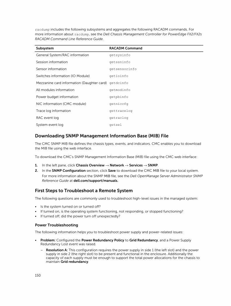
racdump includes the following subsystems and aggregates the following RACADM commands. For
more information about racdump, see the Dell Chassis Management Controller for PowerEdge FX2/FX2s
RACADM Command Line Reference Guide.
Subsystem RACADM Command
General System/RAC information getsysinfoSession information getssninfoSensor information getsensorinfoSwitches information (IO Module) getioinfoMezzanine card information (Daughter card) getdcinfoAll modules information getmodinfoPower budget information getpbinfoNIC information (CMC module) getniccfgTrace log information gettracelogRAC event log getraclogSystem event log getsel
Downloading SNMP Management Information Base (MIB) File
The CMC SNMP MIB file defines the chassis types, events, and indicators. CMC enables you to download the MIB file using the web interface.
To download the CMC's SNMP Management Information Base (MIB) file using the CMC web interface:
1. In the left pane, click Chassis Overview → Network → Services → SNMP.
2. In the SNMP Configuration section, click Save to download the CMC MIB file to your local system.
For more information about the SNMP MIB file, see the Dell OpenManage Server Administrator SNMP Reference Guide at dell.com/support/manuals.
First Steps to Troubleshoot a Remote System
The following questions are commonly used to troubleshoot high-level issues in the managed system:
• Is the system turned on or turned off?
• If turned on, is the operating system functioning, not responding, or stopped functioning?
• If turned off, did the power turn off unexpectedly?
Power Troubleshooting
The following information helps you to troubleshoot power supply and power-related issues:
• Problem: Configured the Power Redundancy Policy to Grid Redundancy, and a Power Supply Redundancy Lost event was raised.
– Resolution A: This configuration requires the power supply in side 1 (the left slot) and the power supply in side 2 (the right slot) to be present and functional in the enclosure. Additionally the capacity of each supply must be enough to support the total power allocations for the chassis to maintain Grid redundancy.
150
– Resolution B: Check if all power supplies are properly connected to the two AC grids: the power supply in side 1 must be connected to one AC grid, the one in side 2 must be connected to the other AC grid, and both AC grids must be working. Grid Redundancy is lost when one of the AC grids is not functioning.
• Problem: The PSU state is displayed as Failed (No AC), even when an AC cord is connected and the power distribution unit is producing good AC output.
– Resolution A: Check and replace the AC cord. Check and confirm that the power distribution unit providing power to the power supply is operating as expected. If the failure still persists, call Dell customer service for replacement of the power supply.
– Resolution B: Check that the PSU is connected to the same voltage as the other PSUs. If CMC detects a PSU operating at a different voltage, the PSU is turned off and marked Failed.
• Problem: Inserted a new server into the enclosure with sufficient power supplies, but the server does not power on.
– Resolution A: Check for the system input power cap setting—it might be configured too low to allow any additional servers to be powered up.
• Problem: Available power keeps changing, even when the enclosure configuration has not changed.
– Resolution: CMC has dynamic fan power management that reduces server allocations briefly if the enclosure is operating near the peak user configured power cap; it causes the fans to be allocated power by reducing server performance to keep the input power draw below System Input Power Cap. This is normal behavior.
• Problem: Overall server performance decreases when the ambient temperature increases in the data center.
– Resolution: This can occur if the System Input Power Cap has been configured to a value that results in an increased power need by fans having to be made up by reduction in the power allocation to the servers. User can increase the System Input Power Cap to a higher value that allow for additional power allocation to the fans without an impact on server performance.
Troubleshooting Alerts
Use the CMC log and the trace log to troubleshoot CMC alerts. The success or failure of each email and/or SNMP trap delivery attempt is logged into the CMC log. Additional information describing the particular error is logged in the trace log. However, since SNMP does not confirm delivery of traps, use a network analyzer or a tool such as Microsoft’s snmputil to trace the packets on the managed system.
Viewing Event Logs
You can view hardware- and chassis logs for information on system-critical events that occur on the managed system.
Viewing Hardware Log
CMC generates a hardware log of events that occur on the chassis. You can view the hardware log using the web interface and remote RACADM.
NOTE: To clear the hardware log, you must have Clear Logs Administrator privilege.
NOTE: You can configure CMC to send email or SNMP traps when specific events occur.
Examples of hardware log entries
critical System Software event: redundancy lostWed May 09 15:26:28 2007 normal System Softwareevent: log cleared was asserted
151
Wed May 09 16:06:00 2007 warning System Softwareevent: predictive failure was assertedWed May 09 15:26:31 2007 critical System Softwareevent: log full was assertedWed May 09 15:47:23 2007 unknown System Softwareevent: unknown event
Viewing Chassis Log
CMC generates a log of the chassis-related events.
NOTE: To clear the chassis log, you must have the Clear Logs Administrator privilege.
Using Diagnostic Console
You can diagnose issues related to the chassis hardware using CLI commands if you are an advanced user or a user under the direction of technical support.
NOTE: To modify these settings, you must have the Debug Command Administrator privilege.
To access the Diagnostic Console:
1. In the left pane, click Chassis Overview → Troubleshooting → Diagnostics.
The Diagnostic Console page displays.
2. In the Command text box, type a command and click Submit.
For information about the commands, see the Online Help.
The diagnostic results page appears.
Resetting Components
You can reset the CMC, or to virtually reset servers making them to behave as if they were removed and reinserted.
NOTE: To reset components, you must have Debug Command Administrator privilege.
NOTE: Virtual reseat is not available for the individual nodes of the PowerEdge FM120x4.
To reset the components using the CMC Web interface,
1. In the left pane, click Chassis Overview → Troubleshooting → Reset Components.
The Reset Components page is displayed.
2. To reset the CMC, in the CMC Status section, click Reset CMC. The CMC that is available is rebooted.
For more information, see the CMC for Dell PowerEdge FX2/FX2s Online Help
Saving or Restoring Chassis Configuration
This is a licensed feature. To save or restore a backup of the Chassis configuration using the CMC Web interface:
152
NOTE: Flexaddress information, server profiles, and extended storage are not saved or restored with the Chassis Configuration. It is recommended to save the Server Profiles that are important separately from the chassis using either a remote file share or a copy saved to a local workstation. For more details on performing these operation, see Adding or Saving Profile
1. In the left pane, click Chassis Overview → Setup → Chassis Backup. The Chassis Backup page is displayed. To save the chassis configuration, click Save. Override the default file path (optional) and click OK to save the file. The default backup file name contains the service tag of the chassis. This backup file can be used later to restore the settings and certificates for this chassis only.
2. To restore the chassis configuration, in the ”Restore" section, click Browse, specify the backup file, and then click Restore.
NOTE: CMC does not reset upon restoring configuration, however CMC services may take some time to effectively impose any changed or new configuration. After successful completion, all current sessions are closed.
Troubleshooting Network Time Protocol (NTP) Errors
After configuring CMC to synchronize the clock with a remote time server over the network, it may take 2-3 minutes before a change in the date and time occurs. If after this time there is still no change, it may be necessary to troubleshoot a problem. CMC may not be able to synchronize the clock for the following reasons:
• Problem with the NTP Server 1, NTP Server 2, and NTP Server 3 settings.
• Invalid host name or IP address may have been accidentally entered.
• Network connectivity problem that prevents CMC from communicating with any of the configured NTP servers.
• DNS problem, preventing any of the NTP server host names from being resolved.
To troubleshoot the NTP–related problems, check the information in the CMC trace log. This log contains an error message for NTP related failures. If CMC is not able to synchronize with any of the configured remote NTP servers, then CMC time is synchronized to the local system clock and the trace log contains an entry similar to the following:
Jan 8 20:02:40 cmc ntpd[1423]: synchronized to LOCAL(0), stratum 10
You can also check the ntpd status by typing the following racadm command:
racadm getractime –n
If the ‘*’ is not displayed for one of the configured servers, the settings may not be configured correctly. The output of this command contains detailed NTP statistics that may be useful in debugging the problem.
If you attempt to configure a Windows-based NTP server, it may help to increase the MaxDist parameter
for ntpd. Before changing this parameter, understand all the implications, since the default setting must
be large enough to work with most NTP servers.
To modify the parameter, type the following command:
racadm config –g cfgRemoteHosts –o cfgRhostsNtpMaxDist 32
After making the change, disable NTP, wait for 5-10 seconds, then enable NTP again:
NOTE: NTP may take an additional three minutes to synchronize again.
153
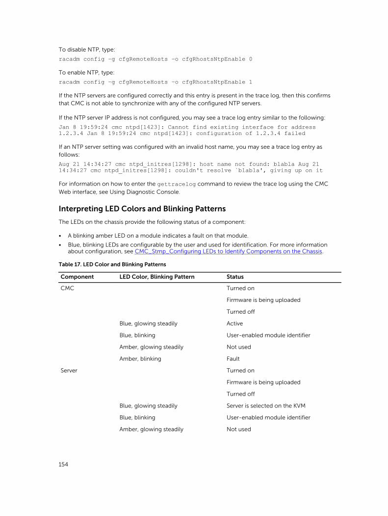
To disable NTP, type:
racadm config –g cfgRemoteHosts –o cfgRhostsNtpEnable 0
To enable NTP, type:
racadm config –g cfgRemoteHosts –o cfgRhostsNtpEnable 1
If the NTP servers are configured correctly and this entry is present in the trace log, then this confirms that CMC is not able to synchronize with any of the configured NTP servers.
If the NTP server IP address is not configured, you may see a trace log entry similar to the following:
Jan 8 19:59:24 cmc ntpd[1423]: Cannot find existing interface for address 1.2.3.4 Jan 8 19:59:24 cmc ntpd[1423]: configuration of 1.2.3.4 failed
If an NTP server setting was configured with an invalid host name, you may see a trace log entry as follows:
Aug 21 14:34:27 cmc ntpd_initres[1298]: host name not found: blabla Aug 21 14:34:27 cmc ntpd_initres[1298]: couldn't resolve `blabla', giving up on it
For information on how to enter the gettracelog command to review the trace log using the CMC
Web interface, see Using Diagnostic Console.
Interpreting LED Colors and Blinking Patterns
The LEDs on the chassis provide the following status of a component:
• A blinking amber LED on a module indicates a fault on that module.
• Blue, blinking LEDs are configurable by the user and used for identification. For more information about configuration, see CMC_Stmp_Configuring LEDs to Identify Components on the Chassis.
Table 17. LED Color and Blinking Patterns
Component LED Color, Blinking Pattern Status
CMC Turned on
Firmware is being uploaded
Turned off
Blue, glowing steadily Active
Blue, blinking User-enabled module identifier
Amber, glowing steadily Not used
Amber, blinking Fault
Server Turned on
Firmware is being uploaded
Turned off
Blue, glowing steadily Server is selected on the KVM
Blue, blinking User-enabled module identifier
Amber, glowing steadily Not used
154
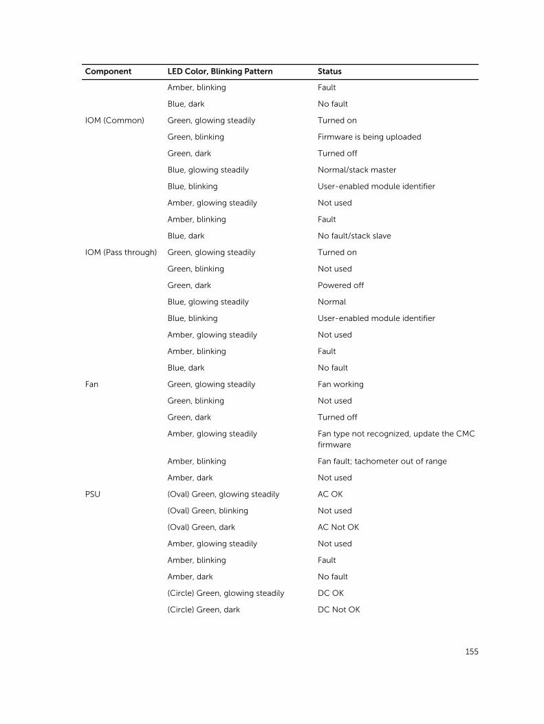
Component LED Color, Blinking Pattern Status
Amber, blinking Fault
Blue, dark No fault
IOM (Common) Green, glowing steadily Turned on
Green, blinking Firmware is being uploaded
Green, dark Turned off
Blue, glowing steadily Normal/stack master
Blue, blinking User-enabled module identifier
Amber, glowing steadily Not used
Amber, blinking Fault
Blue, dark No fault/stack slave
IOM (Pass through) Green, glowing steadily Turned on
Green, blinking Not used
Green, dark Powered off
Blue, glowing steadily Normal
Blue, blinking User-enabled module identifier
Amber, glowing steadily Not used
Amber, blinking Fault
Blue, dark No fault
Fan Green, glowing steadily Fan working
Green, blinking Not used
Green, dark Turned off
Amber, glowing steadily Fan type not recognized, update the CMC firmware
Amber, blinking Fan fault; tachometer out of range
Amber, dark Not used
PSU (Oval) Green, glowing steadily AC OK
(Oval) Green, blinking Not used
(Oval) Green, dark AC Not OK
Amber, glowing steadily Not used
Amber, blinking Fault
Amber, dark No fault
(Circle) Green, glowing steadily DC OK
(Circle) Green, dark DC Not OK
155
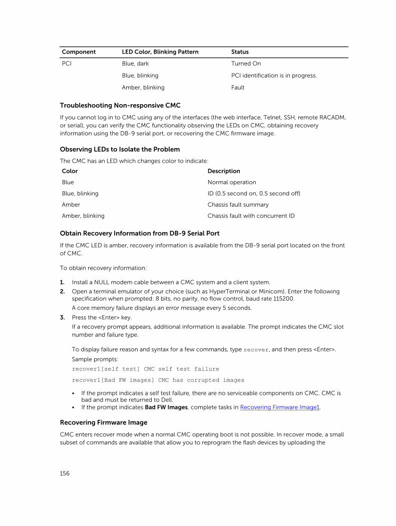
Component LED Color, Blinking Pattern Status
PCI Blue, dark Turned On
Blue, blinking PCI identification is in progress.
Amber, blinking Fault
Troubleshooting Non-responsive CMC
If you cannot log in to CMC using any of the interfaces (the web interface, Telnet, SSH, remote RACADM, or serial), you can verify the CMC functionality observing the LEDs on CMC, obtaining recovery information using the DB-9 serial port, or recovering the CMC firmware image.
Observing LEDs to Isolate the Problem
The CMC has an LED which changes color to indicate:
Color Description
Blue Normal operation
Blue, blinking ID (0.5 second on, 0.5 second off)
Amber Chassis fault summary
Amber, blinking Chassis fault with concurrent ID
Obtain Recovery Information from DB-9 Serial Port
If the CMC LED is amber, recovery information is available from the DB-9 serial port located on the front of CMC.
To obtain recovery information:
1. Install a NULL modem cable between a CMC system and a client system.
2. Open a terminal emulator of your choice (such as HyperTerminal or Minicom). Enter the following specification when prompted: 8 bits, no parity, no flow control, baud rate 115200.
A core memory failure displays an error message every 5 seconds.
3. Press the <Enter> key.
If a recovery prompt appears, additional information is available. The prompt indicates the CMC slot number and failure type.
To display failure reason and syntax for a few commands, type recover, and then press <Enter>.
Sample prompts:
recover1[self test] CMC self test failurerecover1[Bad FW images] CMC has corrupted images
• If the prompt indicates a self test failure, there are no serviceable components on CMC. CMC is bad and must be returned to Dell.
• If the prompt indicates Bad FW Images, complete tasks in Recovering Firmware Image1.
Recovering Firmware Image
CMC enters recover mode when a normal CMC operating boot is not possible. In recover mode, a small subset of commands are available that allow you to reprogram the flash devices by uploading the
156
firmware update file, fx2_cmc.bin. This is the same firmware image file used for normal firmware updates. The recovery process displays its current activity and boots to the CMC OS upon completion.
When you type recover and then press <Enter> at the recovery prompt, the recover reason and available sub-commands display. An example recover sequence may be:
recover getniccfgrecover setniccfg 192.168.0.120 255.255.255.0192.168.0.1recover ping 192.168.0.100recover fwupdate -g -a 192.168.0.100
NOTE: Connect the network cable to the left most RJ45.
NOTE: In recover mode, you cannot ping CMC normally because there is no active network stack. The recover ping <TFTP server IP> command allows you to ping to the TFTP server to verify the LAN connection. You may need to use the recover reset command after setniccfg on some systems.
Troubleshooting Network Problems
The internal CMC trace log allows you to debug CMC alerts and networking. You can access the trace log using the CMC Web interface or RACADM. See the gettracelog command section in the RACADM
Command Line Reference Guide for iDRAC and CMC.
The trace log tracks the following information:
• DHCP — Traces packets sent to and received from a DHCP server.
• DDNS — Traces dynamic DNS update requests and responses.
• Configuration changes to the network interfaces.
The trace log may also contain CMC firmware-specific error codes that are related to the internal CMC firmware, not the managed system’s operating system.
General Troubleshooting
When a success message is displayed after an operation completion, such as saving a Server Profile, sometimes the action may not take effect.
To resolve this issue, check if any of the CMC service ports for SSH, Telnet, HTTP, or HTTPS uses ports commonly used by OS services such as 111. If it is used by CMC service ports, change the settings to a non-reserved port. For more information on reserved ports, see http://www.iana.org/assignments/service-names-port-numbers/service-names-port-numbers.xhtml
157
18Frequently Asked QuestionsThis section lists the frequently asked questions about the following:
• RACADM
• Managing and Recovering a Remote System
• Active Directory
• IOM
RACADM
After performing a CMC reset (using the RACADM racreset subcommand), when a command is entered, the following message is displayed:
racadm <subcommand> Transport: ERROR: (RC=-1)
What does this message mean?
Another command must be issued only after CMC completes the reset.
Using the RACADM subcommands sometimes displays one or more of the following errors:
• Local error messages — Problems such as syntax, typographical errors, and incorrect names. For example, ERROR: <message>
Use the RACADM help subcommand to display correct syntax and usage information. For example, if
you have an error in clearing a chassis log, run the following sub-command.
racadm chassislog help clear
CMC–related error messages — Problems where the CMC is unable to perform an action. The following error message is displayed
racadm command failed.
To view information about a chassis, type the following command.
racadm gettracelog
While using firmware RACADM, the prompt changes to a ">" and the "$" prompt is not displayed again.
If a non-matched double quotation mark (") or a non-matched single quotation (’) is used in the command, the CLI changes to the ">" prompt and queues all commands.
To return to the $ prompt, type <Ctrl>–d.
An error message Not Found is displayed while using the $ logout and $ quit commands.
158
Managing and Recovering a Remote System
When accessing the CMC Web interface, a security warning stating that the host name of the SSL certificate does not match the host name of CMC is displayed.
CMC includes a default CMC server certificate to ensure network security for the web interface and remote RACADM features. When this certificate is used, the web browser displays a security warning because the default certificate is issued to CMC default certificate which does not match the host name of CMC (for example, the IP address).
To address this security concern, upload a CMC server certificate issued to the IP address of CMC. When generating the certificate signing request (CSR) to be used for issuing the certificate, ensure that the common name (CN) of the CSR matches the IP address of CMC (for example, 192.168.0.120) or the registered DNS CMC name.
To ensure that the CSR matches the registered DNS CMC name:
1. In the left pane, click Chassis Overview.
2. Click Network.
The Network Configuration page appears.
3. Select the Register CMC on DNS option.
4. Type a CMC name in the DNS CMC Name field.
5. Click Apply Changes.
Why are the remote RACADM and Web-based services unavailable after a property change?
It may take a minute for the remote RACADM services and the web interface to become available after the CMC Web server resets.
The CMC web server is reset after the following occurrences:
• Changing the network configuration or network security properties using the CMC web user interface.
• The cfgRacTuneHttpsPort property is changed (including when a config -f <config file> changes it).• racresetcfg is used or a chassis configuration backup is restored.• CMC is reset.• A new SSL server certificate is uploaded.
My DNS server doesn’t register my CMC?
Some DNS servers only register names with a maximum of 31 characters.
When accessing the CMC Web interface, a security warning stating that the SSL certificate was issued by a certificate authority that is not trusted is displayed.
CMC includes a default CMC server certificate to ensure network security for the web interface and remote RACADM features. This certificate is not issued by a trusted certificate authority. To address this security concern, upload a CMC server certificate issued by a trusted certificate authority (such as Thawte or Verisign).
Why is the following message displayed for unknown reasons?
159
Remote Access: SNMP Authentication Failure
As part of discovery, IT Assistant attempts to verify the device’s get and set community names. In IT Assistant, the get community name = public and the set community name = private. By default, the community name for the CMC agent is public. When IT Assistant sends out a set request, the CMC agent generates the SNMP authentication error because it only accepts requests from community = public.
Change the CMC community name using RACADM. To see the CMC community name, use the following command:
racadm getconfig -g cfgOobSnmp
To set the CMC community name, use the following command:
racadm config -g cfgOobSnmp -o cfgOobSnmpAgentCommunity <community name>
To prevent SNMP authentication traps from being generated, enter input community names that are accepted by the agent. Since CMC only allows one community name, enter the same get and set community name for IT Assistant discovery setup.
Active Directory
Does Active Directory support CMC login across multiple trees?
Yes. The CMC’s Active Directory querying algorithm supports multiple trees in a single forest.
Does the login to CMC using Active Directory work in mixed mode (that is, the domain controllers in the forest run different operating systems, such as Microsoft Windows 2000 or Windows Server 2003)?
Yes. In mixed mode, all objects used by the CMC querying process (among user, RAC Device Object, and Association Object) must be in the same domain.
The Dell-extended Active Directory Users and Computers Snap-In checks the mode and limits users in order to create objects across domains, if in a mixed mode.
Does using CMC with Active Directory support multiple domain environments?
Yes. The domain forest function level must be in Native mode or Windows 2003 mode. In addition, the groups among Association Object, RAC user objects, and RAC Device Objects (including Association Object) must be universal groups.
Can these Dell-extended objects (Dell Association Object, Dell RAC Device, and Dell Privilege Object) be in different domains?
The Association Object and the Privilege Object must be in the same domain. The Dell-extended Active Directory Users and Computers Snap-In allows to create these two objects in the same domain only. Other objects can be in different domains.
Are there any restrictions on Domain Controller SSL configuration?
160
Yes. All SSL certificates for Active Directory servers in the forest must be signed by the same root certificate authority-signed certificate, because CMC only allows upload of one trusted certificate authority-signed SSL certificate.
The Web interface does not launch after a new RAC certificate is created and uploaded.
If Microsoft Certificate Services is used to generate the RAC certificate, the User Certificate option may have been used instead of Web Certificate, when creating the certificate.
To recover, generate a CSR, create a new Web certificate from Microsoft Certificate Services, and then upload it by running the following RACADM commands:
racadm sslcsrgen [-g] [-f {filename}]
racadm sslcertupload -t 1 -f {web_sslcert}
IOM
After a configuration change, sometimes CMC displays the IP address as 0.0.0.0.
Click the Refresh icon to see if the IP address is set correctly on the switch. If an error is made in setting the IP/mask/gateway, the switch does not set the IP address and returns a 0.0.0.0 in all fields.
Common errors are:
• Setting the out-of-band IP address to be the same as, or on the same network as, the in-band management IP address.
• Entering an invalid subnet mask.
• Setting the default gateway to an address that is not on a network, which is directly connected to the switch.
Event and Error Messages
After you downgrade the CMC firmware from the latest CMC version to earlier versions, why does the Chassis Log displays the following message for some of the logs?
USR8513 - MessageID missing from message registry.
What you see is a new message introduced in the current firmware that older firmware cannot interpret. For more information about the message ID, see the Event and Error Messages Reference Guide under OpenManage Software at www.dell.com/openmanagemanuals.
161