Dell BRC for Simplified Infrastructure Management
43
Business R eady Configurations for Simplified Infrastructure Management A Solution Guide for Dell TM PowerEdge TM blade server, Dell EqualLogic TM storage, and Dell Advanced Infrastructure Manager TM Dell │ End-to-End Solutions Engineering
-
Upload
phu1001gmailcom -
Category
Documents
-
view
226 -
download
0
Transcript of Dell BRC for Simplified Infrastructure Management
8/8/2019 Dell BRC for Simplified Infrastructure Management
http://slidepdf.com/reader/full/dell-brc-for-simplified-infrastructure-management 1/43
Business ReadyConfigurations for SimplifiedInfrastructure Management
A Solution Guide for DellTM PowerEdgeTM blade server,
Dell EqualLogicTM
storage, and Dell AdvancedInfrastructure ManagerTM
Dell │ End-to-End Solutions Engineering

8/8/2019 Dell BRC for Simplified Infrastructure Management
http://slidepdf.com/reader/full/dell-brc-for-simplified-infrastructure-management 2/43
Business Ready Configurations for Simplified Infrastructure Management
Page ii
THIS WHITE PAPER IS FOR INFORMATIONAL PURPOSES ONLY, AND MAY CONTAIN TYPOGRAPHICAL
ERRORS AND TECHNICAL INACCURACIES. THE CONTENT IS PROVIDED AS IS, WITHOUT EXPRESS OR
IMPLIED WARRANTIES OF ANY KIND.
© 2010 Dell Inc. All rights reserved. Reproduction of this material in any manner whatsoever without
the express written permission of Dell Inc. is strictly forbidden. For more information, contact Dell.
Dell, the DELL logo, and the DELL badge, PowerConnect, FlexAddress, OpenManage, and PowerVault
are trademarks of Dell Inc. Intel and Core are either a trademark or a registered trademark of Intel
Corporation in the United States and other countries. Microsoft, Windows, and Active Directory are
registered trademarks, and Hyper-V is a trademark of Microsoft Corporation in the United States and/or
other jurisdictions. Citrix and Xen are either registered trademarks or trademarks of Citrix in the
United States and/or other countries. VMware is a registered trademark of VMWare, Inc. in the United
States or other countries. Red Hat Enterprise Linux a registered trademark of Red Hat, Inc. in the
United States and/or other countries. Oracle is a registered trademark of Oracle Corporation and/or its
affiliates.
Other trademarks and trade names may be used in this document to refer to either the entities
claiming the marks and names or their products. Dell Inc. disclaims any proprietary interest in
trademarks and trade names other than its own.

8/8/2019 Dell BRC for Simplified Infrastructure Management
http://slidepdf.com/reader/full/dell-brc-for-simplified-infrastructure-management 3/43
Business Ready Configurations for Simplified Infrastructure Management
Page iii
8/8/2019 Dell BRC for Simplified Infrastructure Management
http://slidepdf.com/reader/full/dell-brc-for-simplified-infrastructure-management 4/43
Business Ready Configurations for Simplified Infrastructure Management
Page 4
Table of ContentsIntroduction ................................................................................................................ 7
Audience and Scope ....................................................................................................... 7
Overview .................................................................................................................... 7
Hardware ................................................................................................................. 8
Dell PowerEdge Blade Server ...................................................................................... 8
Dell EqualLogic PS6010 Series iSCSI Arrays ...................................................................... 9
Dell PowerConnect 8024F Managed Layer 3 10 Gigabit Ethernet Switches ................................ 9
Software ................................................................................................................ 10
Why Dell blades, Dell EqualLogic, Dell PowerConnect and AIM? ............................................. 10
Simplified Management ........................................................................................... 10
Seamless Scalability ............................................................................................... 11
Optimized Resource Utilization ................................................................................. 11
Roadmap for rolling out an AIM Environment .................................................................... 11
Solution Specification .................................................................................................. 12
How to order .......................................................................................................... 14
Dell Global Services .................................................................................................. 14
Reference Architecture ................................................................................................ 14
Design Principles ...................................................................................................... 14
Starter Configuration ................................................................................................ 14
Redundant Configuration ............................................................................................ 15
Network Architecture ................................................................................................... 16
Design Principles ...................................................................................................... 16
Physical Network ................................................................................................... 17
Virtual Network .................................................................................................... 17
System Control Network ............................................................................................. 17
Other VLANs ........................................................................................................... 17
iSCSI VLAN ........................................................................................................... 18
Lights-out management VLAN ................................................................................... 18
Active Directory VLAN ............................................................................................. 18
Controller VLAN .................................................................................................... 18
Best Practices ......................................................................................................... 18
Routing............................................................................................................... 18
Configuring Dell PowerConnect Ethernet switches ............................................................. 19

8/8/2019 Dell BRC for Simplified Infrastructure Management
http://slidepdf.com/reader/full/dell-brc-for-simplified-infrastructure-management 5/43
Business Ready Configurations for Simplified Infrastructure Management
Page 5
Storage Configuration .................................................................................................. 19
Dell EqualLogic PS6010X ............................................................................................. 19
Volume Size Considerations ......................................................................................... 19
Array RAID Configuration ............................................................................................ 19
Management .............................................................................................................. 20 AIM Management ...................................................................................................... 20
Systems Management ................................................................................................ 20
Storage Management ................................................................................................. 20
Deploying and Configuring the Solution ............................................................................. 21
Phase 1 ................................................................................................................. 21
Install AIM Controller .............................................................................................. 21
Verify Installation .................................................................................................. 23
Installing a Resilient Controller (Optional) .................................................................... 23
Accessing AIM Controller ......................................................................................... 24
Discovering Servers ................................................................................................ 24
Phase 2 ................................................................................................................. 25
Server Power Control.............................................................................................. 25
Migrate OS images to iSCSI target .............................................................................. 25
iSCSI Bootable personas........................................................................................... 28
Phase 3 ................................................................................................................. 33
Discover Network Switches ....................................................................................... 33
Converting the ‘Read-Only’ switches to be ‘Fully Managed’ ............................................... 35
Creating Basic Network Topologies ............................................................................. 35
Phase 4 ................................................................................................................. 36
AIM Agent Installation ............................................................................................. 36
Persona Network Management .................................................................................. 37
Workload Management ............................................................................................ 37
Troubleshooting ....................................................................................................... 37
Best Practices ...................................................................................................... 37
Known Issues ........................................................................................................ 37 Basic Troubleshooting ............................................................................................. 37
References ................................................................................................................ 38
Appendix .................................................................................................................... 1
AIM Console Views ...................................................................................................... 1
Configuring Dell PowerConnect Ethernet switches ............................................................... 3

8/8/2019 Dell BRC for Simplified Infrastructure Management
http://slidepdf.com/reader/full/dell-brc-for-simplified-infrastructure-management 6/43
Business Ready Configurations for Simplified Infrastructure Management
Page 6
8/8/2019 Dell BRC for Simplified Infrastructure Management
http://slidepdf.com/reader/full/dell-brc-for-simplified-infrastructure-management 7/43
Business Ready Configurations for Simplified Infrastructure Management
Page 7
IntroductionThe Business Ready Configurations for Dell™ PowerEdge™ blade servers, Dell PowerConnect™ switches,
Dell EqualLogic™ SAN, and Dell Advanced Infrastructure Manager ™ (Dell AIM) provides a detailed
reference architecture for deploying and utilizing Dell AIM on Dell blades, switches, and iSCSI storage
environments. Based on extensive engineering work in architectural design and certification, customers
can quickly and confidently deploy these proven architectures into production environments, helping toeliminate much of the costly and time-consuming trial and error often encountered during complex
infrastructure design and implementation. The solution is designed to provide a completely managed
infrastructure with the ability to heal itself in the event of failure. The solution includes the network
architectures, switch configurations, storage configurations, and best practices necessary for deploying
and configuring the solution. The solution will help customers achieve the full benefits of Dell AIM, Dell
PowerEdge blade servers, Dell PowerConnect network switches, and Dell EqualLogic PS Series arrays.
Audience and ScopeThe intended audiences for this white paper are IT administrators, IT managers, and channel partners
who are planning to deploy Dell AIM using Dell blade servers, Dell PowerConnect switches, and Dell
EqualLogic SAN. This white paper provides an overview of the recommended servers, switches, storage,
software, and services. It can be used to plan and procure the required components to set up a
virtualization infrastructure.
This white paper provides reference architecture and best practices for deploying and configuring
Dell’s 11th generation blade server – M610, Dell EqualLogic PS6010 Series arrays, and Dell AIM 3.3. The
solution uses iSCSI as the storage environment, and Fibre Channel is not discussed. The solution is
designed to be stand alone, with the blade enclosure(s) and storage arrays connecting to switches
mounted in the rack; based on customer requirements further customization of the recommended
architecture may be required.
Overview This section provides a high-level product overview of the Dell AIM, Dell PowerEdge blade servers, and
Dell EqualLogic PS Series arrays communication through a Dell PowerConnect managed switch
environment.
8/8/2019 Dell BRC for Simplified Infrastructure Management
http://slidepdf.com/reader/full/dell-brc-for-simplified-infrastructure-management 8/43
Business Ready Configurations for Simplified Infrastructure Management
Page 8
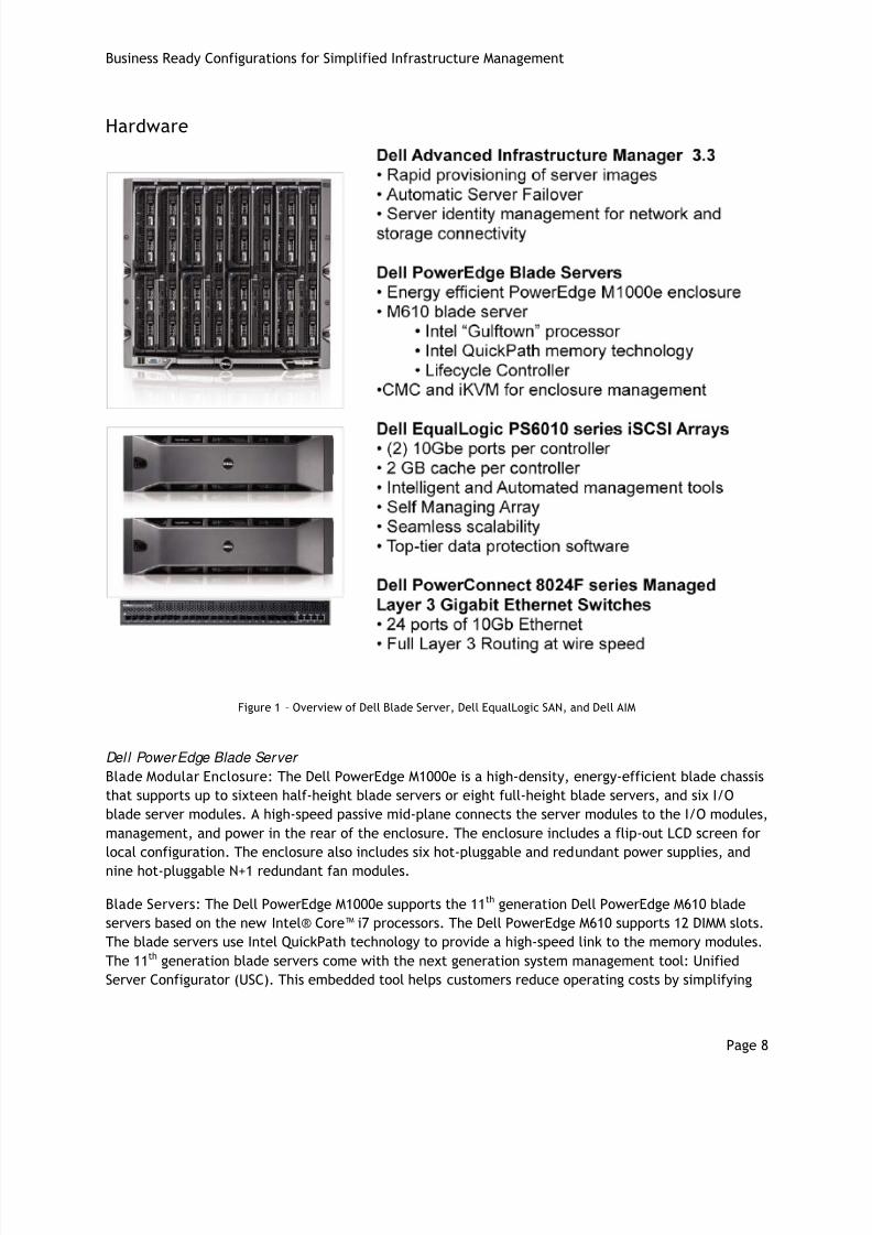
Hardware
Figure 1 – Overview of Dell Blade Server, Dell EqualLogic SAN, and Dell AIM
Dell PowerEdge Blade Server
Blade Modular Enclosure: The Dell PowerEdge M1000e is a high-density, energy-efficient blade chassis
that supports up to sixteen half-height blade servers or eight full-height blade servers, and six I/O
blade server modules. A high-speed passive mid-plane connects the server modules to the I/O modules,
management, and power in the rear of the enclosure. The enclosure includes a flip-out LCD screen for
local configuration. The enclosure also includes six hot-pluggable and redundant power supplies, and
nine hot-pluggable N+1 redundant fan modules.
Blade Servers: The Dell PowerEdge M1000e supports the 11th generation Dell PowerEdge M610 blade
servers based on the new Intel® Core™ i7 processors. The Dell PowerEdge M610 supports 12 DIMM slots.
The blade servers use Intel QuickPath technology to provide a high-speed link to the memory modules.
The 11th generation blade servers come with the next generation system management tool: Unified
Server Configurator (USC). This embedded tool helps customers reduce operating costs by simplifying

8/8/2019 Dell BRC for Simplified Infrastructure Management
http://slidepdf.com/reader/full/dell-brc-for-simplified-infrastructure-management 9/43
Business Ready Configurations for Simplified Infrastructure Management
Page 9
deployment and management, and it supports diagnostics, firmware updates, and hardware
configuration.
I/O Modules: The enclosure provides three redundant fabrics using six I/O modules. The modules can
be populated with Dell PowerConnect switches.
Management: The Dell PowerEdge M1000e has integrated enclosure management through a redundantChassis Management Controller (CMC) module, and an integrated keyboard, video, and mouse (iKVM)
modules.
For more information on Dell blade servers, see http://www.dell.com/blades.
Dell EqualLogic PS6010 Series iSCSI Arrays
The Dell EqualLogic PS6010 is the latest iSCSI storage device from Dell. Its features include two 10 GbE
network ports per controller, faster processors, 2 GB cache per controller, support for RAID 6,
increased drive capacity, and a new monitoring application, SAN HQ, at no additional cost.
In addition to the new features described above, Dell EqualLogic SAN devices provide the following
capabilities:
Reliability: Dell EqualLogic PS6010 Series arrays have hot-swappable redundant components, a
choice of RAID types, and hot-spare disks. They also include the Auto-Stat Disk Monitoring
System (ADMS) that proactively scans disk drives in the background to help detect media
anomalies and correct them.
Scalability: As each array is added to the storage group, the storage capacity and performance,
in terms of both bandwidth and IOPS, are increased. This increased capacity can be utilized
without downtime. EqualLogic PS Series arrays in a SAN work together to automatically manage
data, load balance across all resources, and expand to meet growing storage needs.
Self-Managing Arrays: The arrays offer many self-managing features such as automatic load
balancing and storage tiers. A single storage pool can have different models that offer a range
of capacity and performance parameters. In addition, different arrays in a storage pool can be
configured with different RAID levels, and volumes will automatically be migrated between the
RAID levels based on performance data and usage patterns. All data and volume movement can
be performed online with zero downtime.
Top-Tier Data Protection Software: Advanced data protection features such as Auto
Replication and Auto-Snapshot Manager come standard. Role based administration and a full
suite of data protection, availability and recovery tools to insure data integrity. Instant Volume
Restore, Multi-Path I/O, Multi-Volume, Writeable Snapshots, Volume Cloning, and Volume
Consistency Sets are all included.
For more information on Dell EqualLogic storage, see http://www.dell.com/equallogic.
Dell PowerConnect 8024F Managed Layer 3 10 Gigabit Et hernet Swi t ches
The PowerConnect 8024F is a high density 10 Gb Ethernet switch designed for data center, aggregation,
and unified fabric deployments that require high throughput and availability. These high density 24-
port 10 Gb switches are ready for converged Ethernet environments supporting dense virtualization,
iSCSI storage, and 10Gb traffic aggregation. The 8024F also provides full routing features in a compact
1U form factor with data center friendly front-to-rear cooling.
8/8/2019 Dell BRC for Simplified Infrastructure Management
http://slidepdf.com/reader/full/dell-brc-for-simplified-infrastructure-management 10/43
Business Ready Configurations for Simplified Infrastructure Management
Page 10
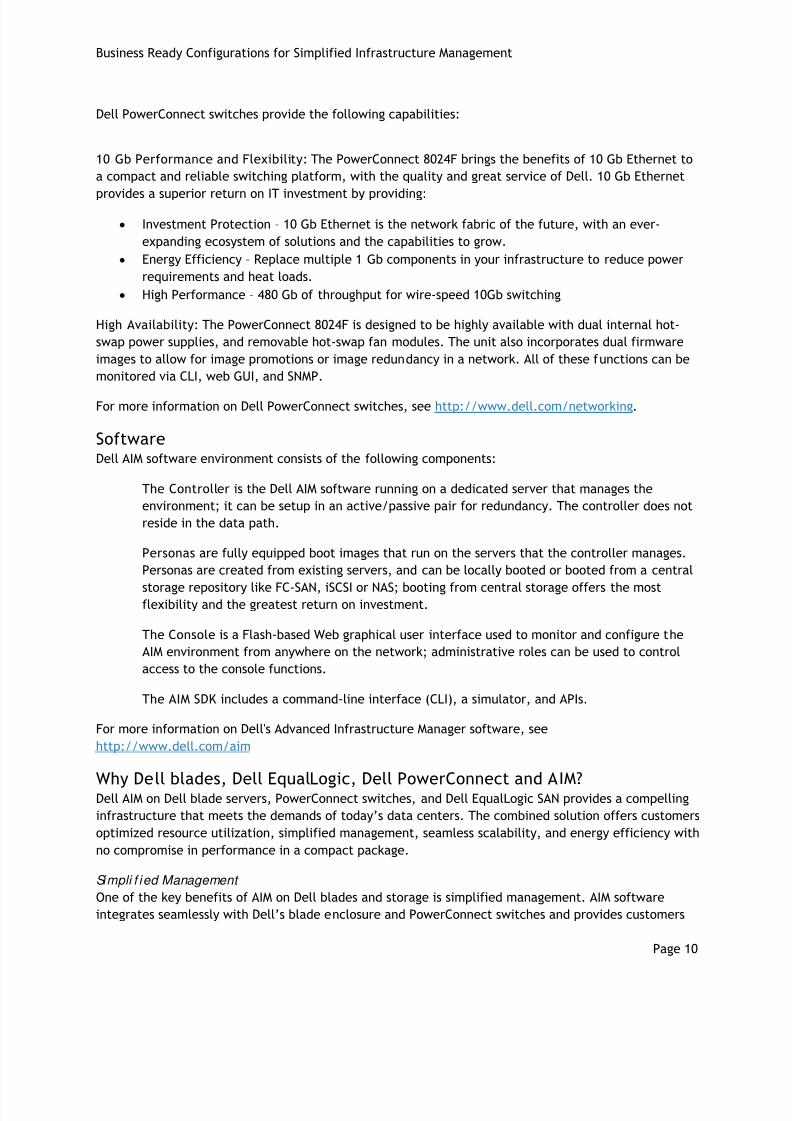
Dell PowerConnect switches provide the following capabilities:
10 Gb Performance and Flexibility: The PowerConnect 8024F brings the benefits of 10 Gb Ethernet to
a compact and reliable switching platform, with the quality and great service of Dell. 10 Gb Ethernet
provides a superior return on IT investment by providing:
• Investment Protection – 10 Gb Ethernet is the network fabric of the future, with an ever-
expanding ecosystem of solutions and the capabilities to grow.
• Energy Efficiency – Replace multiple 1 Gb components in your infrastructure to reduce power
requirements and heat loads.
• High Performance – 480 Gb of throughput for wire-speed 10Gb switching
High Availability: The PowerConnect 8024F is designed to be highly available with dual internal hot-
swap power supplies, and removable hot-swap fan modules. The unit also incorporates dual firmware
images to allow for image promotions or image redundancy in a network. All of these functions can be
monitored via CLI, web GUI, and SNMP.
For more information on Dell PowerConnect switches, see http://www.dell.com/networking.
SoftwareDell AIM software environment consists of the following components:
The Controller is the Dell AIM software running on a dedicated server that manages the
environment; it can be setup in an active/passive pair for redundancy. The controller does not
reside in the data path.
Personas are fully equipped boot images that run on the servers that the controller manages.
Personas are created from existing servers, and can be locally booted or booted from a central
storage repository like FC-SAN, iSCSI or NAS; booting from central storage offers the mostflexibility and the greatest return on investment.
The Console is a Flash-based Web graphical user interface used to monitor and configure the
AIM environment from anywhere on the network; administrative roles can be used to control
access to the console functions.
The AIM SDK includes a command-line interface (CLI), a simulator, and APIs.
For more information on Dell's Advanced Infrastructure Manager software, see
http://www.dell.com/aim
Why Dell blades, Dell EqualLogic, Dell PowerConnect and AIM?Dell AIM on Dell blade servers, PowerConnect switches, and Dell EqualLogic SAN provides a compelling
infrastructure that meets the demands of today’s data centers. The combined solution offers customers
optimized resource utilization, simplified management, seamless scalability, and energy efficiency with
no compromise in performance in a compact package.
Simpli f ied Management
One of the key benefits of AIM on Dell blades and storage is simplified management. AIM software
integrates seamlessly with Dell’s blade enclosure and PowerConnect switches and provides customers

8/8/2019 Dell BRC for Simplified Infrastructure Management
http://slidepdf.com/reader/full/dell-brc-for-simplified-infrastructure-management 11/43
Business Ready Configurations for Simplified Infrastructure Management
Page 11
with a simplified systems management interface. Integration and management through the CMC and
iDRAC connections allows AIM to create and manage virtual network resources, power control, and
storage access. The Dell EqualLogic PS Series arrays provide a single-pane management view of the
entire storage pool in the SAN. The Dell EqualLogic PS6010 Series arrays intelligently balance workloads
across the available arrays with no manual intervention.
Seamless Scalabi l i t y Dell servers and storage provide a highly scalable solution to meet the growing IT demands of today's
data centers. The Dell M1000e enclosure and M610 blade servers with AIM allow for the creation of
server pools that provide automatic persona failover that maximizes uptime. AIM can manage any
number of similar servers and personas, network connections, and storage access.
Opt imi zed Resource Ut il i zat ion
AIM’s ability to rapidly deploy server personas across pools of like servers provides data center
managers the ability to change server roles on demand or using a schedule.
Energy Efficiency
The Dell PowerEdge M1000e enclosure takes advantage of thermal design efficiencies, such as ultra-efficient power supplies and dynamic power-efficient fans with optimized airflow design, to efficiently
cool the chassis and enable better performance in a lower power envelope.
Roadmap for rolling out an AIM EnvironmentAny transformation in data center infrastructure must be rolled out in a planned and thoughtful
manner. The responsibility for data center management, at least in large organizations, can be
distributed amongst multiple functional groups or units – server, storage, networks, and operating
systems/applications. Dell AIM provides a methodology for gradual transformation of a static data
center into a dynamic one; see Figure 2 below. This process is designed to make the transformation
manageable, particularly in environments where existing operational policies must be followed – IP
address administration, network access restrictions, storage security, service level requirements, etc.
This methodology begins with the server department; ultimately, the requirements for a dynamic data
center are driven by this department. Dell provides simple and nonintrusive mechanisms for deploying
a Dell AIM environment and building an inventory of servers. Centralized booting is mandatory for
creating a dynamic data center; Dell AIM includes tools and methodologies for migrating existing
workloads to central storage, and gradually transitioning from local booting to booting from central
storage.
Figure 2 – Methodology for implementing Dell AIM

8/8/2019 Dell BRC for Simplified Infrastructure Management
http://slidepdf.com/reader/full/dell-brc-for-simplified-infrastructure-management 12/43
Business Ready Configurations for Simplified Infrastructure Management
Page 12
The next step in this methodology requires coordination across departments, particularly between the
server and network departments. Dell AIM supports multiple network management modes - such as
read-only, fully managed, shared vs. dedicated control - that allow the network administrators more
control over the pace and the extent of the network changes that will be automated as a result of
dynamic server repurposing.
The final step, automating server image configuration and integration with other management softwarein the ecosystem through Dell AIM abstraction and APIs, completes the transformation.
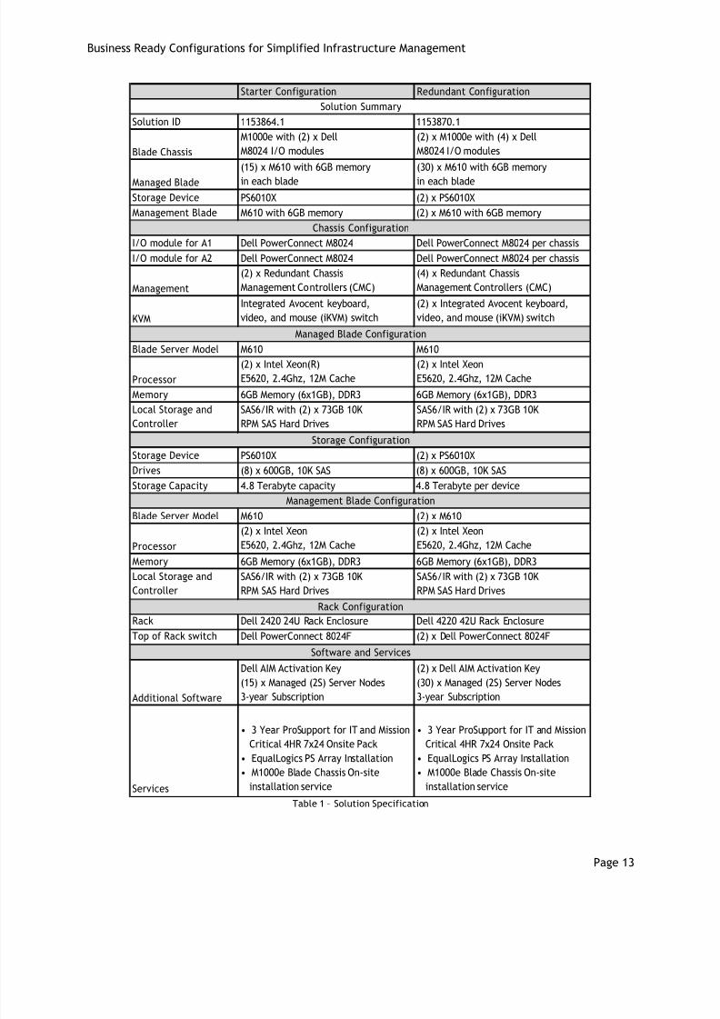
Solution SpecificationThe table on the following page provides specifications for the two business ready configurations. The
remainder of the document discusses reference architectures for these configurations, how to set them
up, and deployment best practices.
8/8/2019 Dell BRC for Simplified Infrastructure Management
http://slidepdf.com/reader/full/dell-brc-for-simplified-infrastructure-management 13/43
Business Ready Configurations for Simplified Infrastructure Management
Page 13
Starter Configuration Redundant Configuration
Solution ID 1153864.1 1153870.1
Blade Chassis
M1000e with (2) x Dell
M8024 I/O modules
(2) x M1000e with (4) x Dell
M8024 I/O modules
Managed Blade
(15) x M610 with 6GB memory
in each blade
(30) x M610 with 6GB memory
in each blade
Storage Device PS6010X (2) x PS6010X
Management Blade M610 with 6GB memory (2) x M610 with 6GB memory
I/O module for A1 Dell PowerConnect M8024 Dell PowerConnect M8024 per chassis
I/O module for A2 Dell PowerConnect M8024 Dell PowerConnect M8024 per chassis
Management
(2) x Redundant Chassis
Management Controllers (CMC)
(4) x Redundant Chassis
Management Controllers (CMC)
KVM
Integrated Avocent keyboard,
video, and mouse (iKVM) switch
(2) x Integrated Avocent keyboard,
video, and mouse (iKVM) switch
Blade Server Model M610 M610
Processor
(2) x Intel Xeon(R)
E5620, 2.4Ghz, 12M Cache
(2) x Intel Xeon
E5620, 2.4Ghz, 12M Cache
Memory 6GB Memory (6x1GB), DDR3 6GB Memory (6x1GB), DDR3
Local Storage and
Controller
SAS6/IR with (2) x 73GB 10K
RPM SAS Hard Drives
SAS6/IR with (2) x 73GB 10K
RPM SAS Hard Drives
Storage Device PS6010X (2) x PS6010X
Drives (8) x 600GB, 10K SAS (8) x 600GB, 10K SAS
Storage Capacity 4.8 Terabyte capacity 4.8 Terabyte per device
Blade Server Model M610 (2) x M610
Processor(2) x Intel XeonE5620, 2.4Ghz, 12M Cache
(2) x Intel XeonE5620, 2.4Ghz, 12M Cache
Memory 6GB Memory (6x1GB), DDR3 6GB Memory (6x1GB), DDR3
Local Storage and
Controller
SAS6/IR with (2) x 73GB 10K
RPM SAS Hard Drives
SAS6/IR with (2) x 73GB 10K
RPM SAS Hard Drives
Rack Dell 2420 24U Rack Enclosure Dell 4220 42U Rack Enclosure
Top of Rack switch Dell PowerConnect 8024F (2) x Dell PowerConnect 8024F
Additional Software
Dell AIM Activation Key
(15) x Managed (2S) Server Nodes
3-year Subscription
(2) x Dell AIM Activation Key
(30) x Managed (2S) Server Nodes
3-year Subscription
Services
• 3 Year ProSupport for IT and Mission
Critical 4HR 7x24 Onsite Pack
• EqualLogics PS Array Installation
• M1000e Blade Chassis On-site
installation service
• 3 Year ProSupport for IT and Mission
Critical 4HR 7x24 Onsite Pack
• EqualLogics PS Array Installation
• M1000e Blade Chassis On-site
installation service
Management Blade Configuration
Software and Services
Solution Summary
Chassis Configuration
Managed Blade Configuration
Storage Configuration
Rack Configuration
Table 1 – Solution Specification
8/8/2019 Dell BRC for Simplified Infrastructure Management
http://slidepdf.com/reader/full/dell-brc-for-simplified-infrastructure-management 14/43
Business Ready Configurations for Simplified Infrastructure Management
Page 14
How to orderTo order the solution discussed in this paper, contact your Dell Sales Representative with the Solution
ID provided above; customers can order either of the two pre-configured solutions. The configurations
can be customized to fit specific needs; depending on the customization, some of the best practices
discussed in this white paper may not apply.
The solution can also be directly ordered online using this link to Dell Business Ready Configurations for
Simplified Infrastructure Management: http://www.dell.com/aim. Configuration customizations can be
made using the Dell online ordering tool.
Dell Global ServicesToday’s financial environment dictates that IT reduces its budget, while still providing ever-increasing
infrastructure services. To assist in reaching this goal, Dell Global Services can be engaged to order the
solution. Dell Global Services helps customers find the “better path” to a virtual-ready infrastructure
that reduces total cost of ownership, increases ROI and agility, and reclaims IT resources.
Reference Architecture This section describes the solution reference architecture.
Design PrinciplesThe following principles were used during the design of this architecture.
• Redundancy with no single point of failure: Redundancy is incorporated in every aspect of the
solution, including networking and storage.
• Scalability: The solution is highly scalable, and is based on the M1000e chassis and PS6010
series arrays. Guidelines to deploy additional blade servers and storage to increase the
compute and storage capacity are also included.
• Isolated, redundant, and high-performance network design: The network is designed tosupport isolation of various networks through the use of VLANs. It is designed to have no single
point of failure, and have optimal performance when used in conjunction with Dell AIM.
Starter ConfigurationThis solution contains a Dell M1000e chassis populated with M610 blade servers. One blade is used for
management (AIM Controller), and the rest run iSCSI-booted personas managed by the controller. A
PowerConnect 8024F switch serves as a top-of-rack switch, and connects the EqualLogic PS6010X array
to the network. Figure 3 illustrates the high-level architecture for the solution using the starter
configuration described in the specification table.

8/8/2019 Dell BRC for Simplified Infrastructure Management
http://slidepdf.com/reader/full/dell-brc-for-simplified-infrastructure-management 15/43
Business Ready Configurations for Simplified Infrastructure Management
Page 15
Figure 3 – Starter Configuration
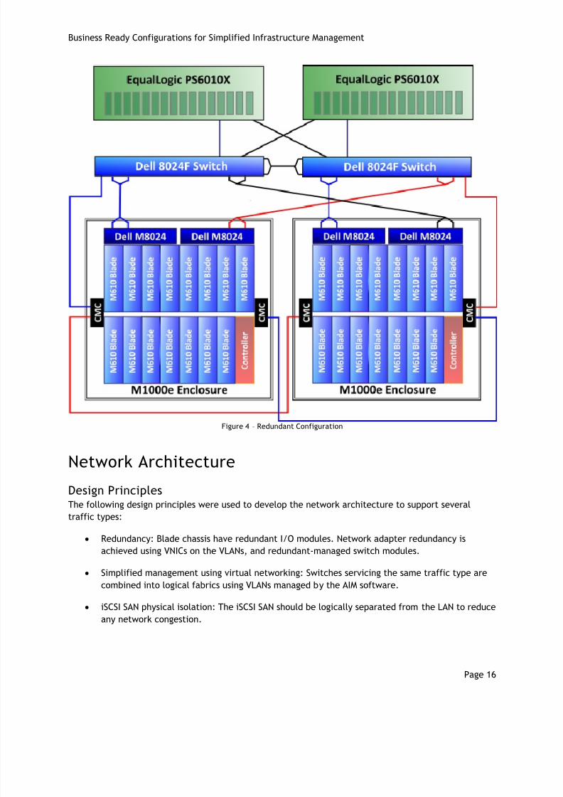
Redundant ConfigurationThis solution consists of two Dell M1000e chassis populated with M610 blade servers. One blade in each
chassis is used for management (resilient AIM Controllers), and the rest run iSCSI-booted personas
managed by the controllers. Two PowerConnect 8024F switches serve as top-of-rack switches, and
connect the two EqualLogic PS6010X arrays to the network. The EqualLogic arrays are configured in a
storage group, allowing the servers to access them from a single group address. Figure 4 illustrates the
high-level architecture for the solution using the redundant configuration described in the specification
table.
8/8/2019 Dell BRC for Simplified Infrastructure Management
http://slidepdf.com/reader/full/dell-brc-for-simplified-infrastructure-management 16/43
Business Ready Configurations for Simplified Infrastructure Management
Page 16
Figure 4 – Redundant Configuration
Network Architecture
Design PrinciplesThe following design principles were used to develop the network architecture to support several
traffic types:
• Redundancy: Blade chassis have redundant I/O modules. Network adapter redundancy is
achieved using VNICs on the VLANs, and redundant-managed switch modules.
• Simplified management using virtual networking: Switches servicing the same traffic type are
combined into logical fabrics using VLANs managed by the AIM software.
• iSCSI SAN physical isolation: The iSCSI SAN should be logically separated from the LAN to reduce
any network congestion.
8/8/2019 Dell BRC for Simplified Infrastructure Management
http://slidepdf.com/reader/full/dell-brc-for-simplified-infrastructure-management 17/43
Business Ready Configurations for Simplified Infrastructure Management
Page 17
• Optimal performance: Link aggregation and iSCSI load balancing is used to achieve the highest
throughput possible.
Physical Net work
The solution network consists of a blade chassis connected to interconnect switches. The Dell blade
chassis can support three separate fabrics; this solution will use only the second “B” fabric. Each blade
chassis will contain two Dell M8024 PowerConnect switch modules. Each switch module will beconnected to an interconnect switch, a Dell PowerConnect 8024F, using an aggregated link of two
ports. Each switch module also has one connection from each iSCSI storage controller to each switch.
To support the 10 Gb infrastructure, each M610 blade will have one Broadcom 57711 Dual Port 10GbE
I/O Card.
For the Redundant configuration, the interconnect switches also connect to each other using an
aggregated link of two ports. The Redundant configuration provides redundancy using the second
switch, and redundant cable pathways.
Virt ual Network
Virtual networks behave in much the same way in an AIM-managed environment as conventional
networks in a conventional data center, except that they’re comprised of virtual LANs (VLANs) running
over physical NICs, switches, and cables, instead of those physical elements themselves.
Because these are virtual networks, it is easier for AIM to create and manage them when compared to
conventional networks: simply drag as many vSwitches, vNICs, and other resources as needed into the
workspace in the Virtual Networks view, draw cables between them to connect them, experiment with
different topologies, and configure all their properties in the console. There is no need to configure
physical NICs on individual machines, configure physical switches, or move physical cables.
Now virtual LANs can be created that segregate network traffic without the constraints of physical
LANs; controller-assigned networks simplify how IP address ranges are allocated and managed.
System Control NetworkThe AIM Controller uses the System Control Network (SCN) to discover new servers and their
capabilities, communicate status and configuration changes between itself and the personas and
VMRacks, connect servers with the network storage devices that contain the personas and VMRacks
boot images, and to manage many other aspects of how personas are configured, including how they
are connected to virtual networks.
For communication from the controller to elements that aren’t on the System Control Network (SCN),
such as persona storage servers, chassis and server management modules, switch management
interfaces, and so on, the controller must have a route to those networks, which typically is the
default gateway for the controller’s real IP addresses. In a typical production deployment, the
controller is connected to a network that is independent of the AIM environment.
Because the controller responds to DHCP requests from elements on the SCN in the AIM environment,
the controller (or at least its connection to the SCN Services interface) should reside in its own
broadcast domain to prevent responses to DHCP requests from servers it doesn’t manage.
Other VLANsFollowing are some examples of additional VLANs that can be created in a virtual-ready infrastructure.

8/8/2019 Dell BRC for Simplified Infrastructure Management
http://slidepdf.com/reader/full/dell-brc-for-simplified-infrastructure-management 18/43
Business Ready Configurations for Simplified Infrastructure Management
Page 18
iSCSI VLAN
This solution isolates iSCSI traffic to a dedicated iSCSI VLAN; this VLAN provides access to the PS6010
storage that houses the network-booted persona images.
Lights-out management VLAN
The vRack (blade chassis) servers’ Chassis Management Controllers (CMC) will have addresses on these
networks and are connected to them. The router transmits traffic between this network and thecontroller’s controller services address or to the controller’s SNMP trap collector address if a separate
address was configured for it.
Acti ve Dir ect ory VLAN
A VLAN is created that allows for a separate broadcast domain for Active Directory® services, such as
DHCP and DNS. A separate network ensures that client DHCP requests are not answered by the
controller.
Contr oll er VLAN
A VLAN-dedicated that the controllers connect to that is in its own broadcast domain, so it doesn’t
interfere with DHCP servers for elements that aren’t in the AIM environment. The controllers’ real IP
addresses (set in their operating systems), and the controller services virtual IP address are on thisnetwork.
Best PracticesThe System Control Network (SCN) is VLAN 4004. This VLAN contains the SCN discovery, DHCP and PXE
services; both of the controllers, all switches, and all managed servers should use this network. In both
configurations, the PowerConnect 8024F switches should be configured as routers to enable
communication across all VLANs. In the redundant configuration, setting up Virtual Router Redundancy
Protocol (VRRP) allows routing to continue even if one of the two interconnect switches fail. When
configuring AIM’s switch permissions, all ports not being controlled by AIM should be set as
“Unmanaged,” any port not marked as “Unmanaged” will be shut down automatically if it is not
configured in the console.
Any VLAN manually created in the Dell AIM environment (such as the private VLAN used between
resilient controllers) that are to remain active once AIM takes full control of switches must have an
external network with the same VLAN created in the AIM console.
Rout ing
Routing between all of the VLANs and the SCN must be properly configured in order for the AIM
controllers to monitor and manage the VLANs and their associated resources; the AIM controller must
have access to all networks that contain manageable resources.
8/8/2019 Dell BRC for Simplified Infrastructure Management
http://slidepdf.com/reader/full/dell-brc-for-simplified-infrastructure-management 19/43
Business Ready Configurations for Simplified Infrastructure Management
Page 19
Configuring Dell PowerConnect Ethernet switchesWhen the network switches are set up, they need to be configured for the AIM controller to manage
them; this is accomplished by connecting to the switch using the CMC for M8024 switches, or through to
serial console for 8024F switches. The System Control Network (SCN) needs to be added to the
switches, and aggregated links configured for maximum throughput and resiliency; this configuration is
detailed in Appendix B.
Storage Configuration
Dell EqualLogic PS6010XThere is a separate storage recommendation for each solution configuration.
Starter Configuration: This configuration uses a single Dell EqualLogic PS6010X array. A single storage
group is created and assigned an IP address on the iSCSI VLAN. The storage contained in the array is
used to store the Dell AIM database and all iSCSI-booted personas. If more storage is needed, another
array can be installed and added to the original storage group. Once the additional array is added to
the group, it will be available to the environment.
Redundant Configuration: The redundant configuration uses two Dell EqualLogic PS6010X arrays. As
with the starter configuration, a storage group is created on the first array and an IP address is
assigned on the iSCSI VLAN. Once the array and group are configured, the second array can be added to
the storage group and the combined storage is made available to the environment. Additional arrays
can be added to provide more storage capacity if needed.
PS Series arrays provide dynamic load balancing; as the workload changes, volume data and network
I/O are load balanced within and across the arrays in a group with no impact on applications and with
no user intervention. The more disk spindles available the better the overall performance will be,
because all active disks per array are always utilized and data is spread across all disks within the RAID
sets per 3U enclosure.
All iSCSI traffic travels over standard switched networks, and the Dell AIM solution is designed to
manage these networks; these features make iSCSI storage a particularly compelling storage solution in
this environment.
For more information on Dell EqualLogic storage, see: http://www.dell.com/equallogic.
Volume Size ConsiderationsVolume sizes depend on the customer environment and the workload type. Remember to size the
volume appropriately to allow space for all software and updates required for the persona’s intended
function. Thin-provisioning can be utilized to allow volumes to grow on demand when additional
storage is necessary, and will increase storage utilization efficiency.
Array RAID ConfigurationThe RAID type selected is highly dependent on the environment workload; the Dell EqualLogic PS6010
array supports four RAID types – RAID 5, RAID 6, RAID 10, and RAID 50. RAID 10 generally provides
maximum throughput and performance at the expense of storage capacity. RAID 50 provides more
usable storage, but has less performance than RAID 10 in random I/O situations and requires additional

8/8/2019 Dell BRC for Simplified Infrastructure Management
http://slidepdf.com/reader/full/dell-brc-for-simplified-infrastructure-management 20/43
Business Ready Configurations for Simplified Infrastructure Management
Page 20
overhead in the case of a drive failure. RAID 5 provides the most storage capacity at the expense of
slightly lower performance and availability.
Management
AIM ManagementThe AIM software solution provides unified infrastructure resource management in a data center. The
data center abstraction provided by AIM effectively unifies the management of a data center
infrastructure that can be heterogeneous in each and every operating department. Data center
infrastructure is constantly undergoing change, and the abstraction provided by AIM insulates higher-
order management software from underlying infrastructure changes. Access to the abstraction is
provided conveniently through a command line interface and Web services. The architecture presented
in this document is homogeneous, comprised of Dell PowerEdge blade servers and Dell PowerConnect
switches, but the true value of AIM is its ability to manage a heterogeneous infrastructure. This type of
infrastructure can include heterogeneous servers (regardless of form factor, make and model), network
switches, and central storage repositories. AIM also provides unified management of physical and
virtual resources, like hypervisors such as VMware® ESX, Microsoft® Hyper-V™, and Xen®, as well as
virtual machines that are deployed on these hypervisors.
Systems ManagementThe following tools and software can be used to manage the hardware.
Dell OpenManage™
Dell OpenManage Server Administrator (OMSA) can be installed on Dell AIM personas and used to
manage the host hardware. For more information on Dell OpenManage and its capabilities, see
www.dell.com/openmanage.
Deployment and change management using Unified Server Configurator (USC)
The Dell PowerEdge M610 blade servers contain USC; this helps customers reduce operating costs by
simplifying deployment and management. Key features include: diagnostics, self-update (UEFI, Driver
Pack update), firmware updates (BIOS, NIC FW, RAID Controllers), and hardware configuration.
Out-of-band CMC and iDRAC
CMC provides a single, secure interface to manage the inventory, configuration, monitoring, and
alerting for chassis components (iKVM, CMC), I/O modules, servers, and iDRAC. It also provides
excellent real-time power management, monitoring, and alerting capabilities. The Dell chassis also
provides system-level power limiting, slot-based prioritization, and dynamic power engagement
functionality. iDRAC on each server provides the flexibility to remotely manage the server through
console redirection, and virtual CD-ROM/DVD/floppy/flash capabilities.
Storage ManagementDell EqualLogic provides a rich set of management features that are available at no additional cost,
and come with exceptionally easy-to-use management tools. For more information on Dell EqualLogic
features and management capabilities, see www.dell.com/equallogic.

8/8/2019 Dell BRC for Simplified Infrastructure Management
http://slidepdf.com/reader/full/dell-brc-for-simplified-infrastructure-management 21/43
Business Ready Configurations for Simplified Infrastructure Management
Page 21
Deploying and Configuring the Solution
Phase 1
Inst all AIM Contr oll er
Pre-Requisit es
The AIM Controller can be installed in a dedicated blade server with the following minimum
configuration:
• 2 CPUs (two sockets).
• 2 GB of RAM.
• 40 GB hard disk.
• An optical drive to install Red Hat Enterprise Linux® and AIM software on the server
One of the server NICs set aside to function as the controller will be used to connect to the AIM
environment, to host the console and SDK connections, receive SNMP traps, connect to managed
devices, and connect to storage arrays.
To install the AIM Controller, you will need:
• A licensed copy of the Red Hat Enterprise Linux 5 Update 4 operating system
• AIM Linux ISO distribution
It is advised to review the AIM Pre-Installation Checklist included with the “Deployment Planning and
Controller Installation Guide”. When installing the controller software, one of the two controller
installation options must be selected: basic or advanced.
Installation checklist
A basic installation prompts for the minimum information required to install the controller. Any
additional configuration changes are made by connecting to the AIM console and using its graphical user
interface. This is the best choice for a stand-alone deployment.
The following information is needed before beginning the installation process:
1. Controller IP address – This is the IP address that is assigned to the server’s primary NIC and is
configured during the OS installation process.
2. System ID – More than one AIM environment can be installed in the same data center, or in data
centers that can communicate with each other. To ensure that the MAC addresses and other
configurations the controller creates are unique, a unique number from 0 to 31 must be
assigned to each AIM environment when installed.
3. Controller Services Virtual IP Address – This is the IP address configured to host the three
controller services: AIM console access (from GUI, CLI and SDK), communication with elements
in the AIM environment, and receive SNMP traps sent by network switches and other devices. In

8/8/2019 Dell BRC for Simplified Infrastructure Management
http://slidepdf.com/reader/full/dell-brc-for-simplified-infrastructure-management 22/43
Business Ready Configurations for Simplified Infrastructure Management
Page 22
a basic installation, a single IP address is configured to host all three services; this is a virtual
IP address and gets instantiated when the controller starts and typically binds to the same NIC
that the controller’s real IP address is configured to use.
4. System Control Network (SCN) and AIM DHCP – This is a private network used by the controller
to communicate with the managed entities in the AIM environment. The AIM DHCP network is
used temporarily during the new server discovery process. The range of IPs for both networkscan be modified post installation; however, it is preferable to have this information entered in
during the installation process.
Note: Dell FlexAddress™ should not be used in conjunction with the Dell AIM solution.
Inst all at ion Process
1. Install the Red Hat 5 Update 4 operating system on the server set aside to function as the
AIM controller; the default settings should suffice with the exception of SELINUX which
should be disabled. This can be done during the installation or later. Detailed instructions
can be found in the “Deployment Planning and Controller Installation Guide”. It is
recommended that iptables is enabled prior to installing the controller software.
2. Install and configure AIM controller software using the steps listed below.
a. Mount the AIM Linux media, and install the controller RPMs (packages) by executing
the installController.sh utility found in the root directory of the image. This
utility will also install any missing OS packages needed for AIM controller function;
this process will typically take less than 5 minutes.
b. Configure the AIM controller by executing the
/opt/scalent/bin/setupController.sh utility. This utility will bring up a
wizard that walks through the configuration process; the questions are self
explanatory and customers should pick the “Basic Installation”. Once theinformation detailed in the previous step is entered, the utility configures the
installation.
c. Once the installation is complete, the utility will prompt to copy the license.dat
file provided when the software was registered to the
/var/opt/scalent/license directory on the controller. After the file is in
place, run the comment service scalent start to start the controller service.
Note that in a “Basic” installation, very few inputs are needed during the configuration process. The
installer will assume default values for all the networks that are managed by the AIM controller, and
these are listed below.
Infrastructure VLAN range– The VLAN range that the controller uses to create the infrastructure thatsupports the AIM environment, including the System Control Network (SCN). The default range is VLAN4002 to VLAN 4089, and the default SCN VLAN is 4004.
Scalent Assigned VLAN range – The VLAN range available to the controller to assign to newly createdvirtual networks; the default range is VLAN 3746 to VLAN 4001.
Customer Assigned VLAN range – The VLAN range assigned to virtual networks created in theenvironment; the default range is VLAN 2 to VLAN 3745.
8/8/2019 Dell BRC for Simplified Infrastructure Management
http://slidepdf.com/reader/full/dell-brc-for-simplified-infrastructure-management 23/43
Business Ready Configurations for Simplified Infrastructure Management
Page 23
VLANs that are not in one of these ranges are not managed by the controller.
Veri fy Inst allat ion
After the installation process completes, it can be verified by checking if the Scalent service is running.
The controller can be easily accessed through the AIM console. Open a Web browser on any system that
has connectivity to the network where the AIM controller is installed. Enter the AIM controller services
virtual IP address in the URL. The default user name and password to login to the AIM console are bothadmin. On the initial log in, the environment will have no elements under management. The AIM
console provides multiple views of the environment, and the most commonly used views are the
physical network, virtual network, and catalog views.
Physical Network View – This view shows all the physical elements of the environment, including
physical network switches and their ports, chassis, blades, servers, external switch ports, and physical
cabling.
Virtual Network View – This view enables creation of a network topology comprising of server images
(or personas). The personas are interconnected by means of virtual switches (VLANs) and virtual cables.
Cat alog View – The AIM controller manages a variety of elements in the environment, includingservers, racks, personas, switches, and so on. The catalog view groups like elements together, and
presents them either in the form of a list or icons.
Other information entered during the configuration process (SCN and DHCP address range, System ID,
etc) can be seen in the environment view of the AIM Console. Sample screenshots of the various views
provided by the AIM console have been included in Appendix A.
Inst all ing a Resil ient Contr oll er (Opt ional)
In order to protect against the failure of a single controller, AIM provides an option to install and
configure a secondary controller that can be done during the initial install or at a later stage.
Pre-Requisit es
To deploy a pair of resilient controllers, you will need:
1. Oracle® Cluster File System 2 (OCFS2) installation on both servers that will function as AIM
controllers; the software packages are included in the AIM distribution.
2. Shared database location – The resilient controllers need to have access to a common shared
data store that functions as the AIM configuration repository. The shared data store is a 10 GB
data LUN on the Dell EqualLogic iSCSI SAN. Details on configuring the shared storage are in the
“Deployment Planning and Controller Installation Guide”.
3. OCFS2 Heartbeat Network - This is a dedicated network between the OCFS2 controllers and the
lock manager to exchange keep-alive traffic. In a blade environment, this is accomplished by
assigning a unique VLAN to the switch ports connected to the NICs configured for the private
network.
Inst all at ion Process
Installing the secondary controller is very similar to the process described earlier for installing a single
controller.
1. Install the Red Hat 5 Update 4 Operating System on the both of the controllers.

8/8/2019 Dell BRC for Simplified Infrastructure Management
http://slidepdf.com/reader/full/dell-brc-for-simplified-infrastructure-management 24/43
Business Ready Configurations for Simplified Infrastructure Management
Page 24
2. Verify that both controllers can access the shared LUN, and can communicate on the dedicated
heartbeat network. If the hosts are not stored in DNS, the host names have to be manually
added to the /etc/hosts file on both of the hosts.
3. Install the OCFS2 packages from the AIM software distribution using the following command:
installcontroller.sh resilient=yes on the primary node.
4. Configure the controller using the /opt/scalent/bin/setupcontroller.sh utility, and
enter the OCFS2-related information during the installation process.
5. Repeat steps 3 and 4 on the secondary Controller.
Accessing AIM Cont rol ler
In addition to the Web console, the AIM controller can be accessed using the CLI in two ways:
1. On the AIM Controller server – Login to the controller using a secure session, and execute the
command /opt/scalent/bin/sdk. This will bring up the AIM CLI prompt, providing an
optional argument tty=true that enables tab completion for the CLI session.
2. Any Windows® Client – The AIM SDK client can be installed and invoked on any desktop/server
running Windows XP or later. Typically, the executables are stored in the
C:\Scalent\SDK\bin folder and the CLI is started by executing the voeCli.bat script.
Once the CLI starts up, the following two commands need to be executed:
OPEN
SET HOST=<IP Address of AIM Controller>
Discovering Servers
The AIM controller can discover servers running in the data center without having to install any agent
software. Server discovery tools for each of the supported operating systems are included in the AIM
software distribution.
1. Servers running Windows: Login to the server as an administrator, and configure the Windows
firewall to allow ICMP requests. This can be done from the GUI, or by entering the following
command:
>netsh firewall set icmpsetting 8 enable
Execute the batch file discovery\discover.bat from the AIM software distribution for
Windows; there is no need to copy the utility to the server.
2. Servers running Linux: Login to the server as the root user, and run the shell script
discover.sh from the root directory of the AIM software distribution for Linux; the softwaredoes not have to be copied or installed on the server.
Discovering Bare Metal Servers: For servers that do not contain an operating system, the discovery
process is different. After the server is powered on, the BIOS needs to be configured, and PXE booting
on one or both of the NICs should be enabled. When the server starts booting, the AIM controller will
respond to the PXE boot requests and boot a discovery image on the server. The discovery image will
inspect the system configuration, and the information is stored in the AIM configuration repository.
8/8/2019 Dell BRC for Simplified Infrastructure Management
http://slidepdf.com/reader/full/dell-brc-for-simplified-infrastructure-management 25/43
Business Ready Configurations for Simplified Infrastructure Management
Page 25
Note: Dell FlexAddress should not be used in conjunction with the Dell AIM solution.
Phase 2
Server Power Cont rol
During the server discovery process, the AIM controller also discovers the information needed to accessand login to the Integrated Dell Remote Access Controller (iDRAC) on the servers; for blades the
needed information is related to the IPMI interface. After the server discovery process completes, this
information can be accessed from the AIM console for each of the discovered servers. At this stage, the
servers can be powered on/off from the AIM console regardless of whether they are disk booted or net
booted.
In the AIM console physical view, point to the server running Windows that was discovered using the
server discovery utility. The lights-out management can be entered by selecting the ‘management
settings’ associated with that server. After entering that information, the server can be powered off by
clicking on the Stop Persona link. Servers running a Windows OS need to be powered off before
proceeding to the next step.
NOTE: Before shutting down the server, there is one important step that is essential for the image
to be able to boot over iSCSI. Log into the Microsoft Windows server, and ensure that the Microsoft
iSCSI initiator is installed and enabled for booting; this is handled differently if it is a Windows
2003 or a Windows 2008 image that is being migrated.
Windows 2008 – By default a Windows 2008 installation includes the Microsoft iSCSI boot initiator.
iSCSI boot should be enabled using the Server Migration Utility (SMU) provided with AIM in the next
section.
Windows 2003 – If the initiator is not already installed, download the initiator with boot support
from Microsoft for the appropriate architecture – 32 or 64 bit. While installing the iSCSI initiator,
the boot over iSCSI option should be checked, and all appropriate NICs on the server should beselected.
Migrat e OS images t o iSCSI t ar get
Storage Configuration
Before proceeding with the migration process, a volume of appropriate size needs to be created in the
storage array and set up with the appropriate volume access control. If creating a Windows OS image,
the volume can be created from within the Server Migration Utility (SMU), and does not need
preconfiguration. Otherwise, it can be created using the Dell EqualLogic Group Manager Management
tool; refer the product documentation for detailed instructions.
Server Migration Utility
The AIM software includes migration utilities for Windows and Linux. The primary function of these
utilities is to copy boot and data images from a local disk to a central storage repository. After the
migration, the utility also can enable iSCSI booting on Windows 2008 servers and carry out offline

8/8/2019 Dell BRC for Simplified Infrastructure Management
http://slidepdf.com/reader/full/dell-brc-for-simplified-infrastructure-management 26/43
Business Ready Configurations for Simplified Infrastructure Management
Page 26
editing to enable the image to boot from central storage on the source server, as well as other
compatible servers; in this paper, we focus on migrating to the Dell EqualLogic iSCSI storage array.
Windows edition
The migration utility is one of the media kit DVDs, or customers can download the bootable ISO that
can be burned onto a DVD/CD or copied to a bootable USB drive. The server to be imaged needs to beshut down and booted into the migration utility; the migration utility that is based on Microsoft
Windows Preinstallation Environment (Windows PE) presents a menu-driven interface. Use the following
steps to complete the migration:
1. From the Main Menu in the migration utility, select the following: Go to Advanced Operations
-> Provision iSCSI LUN. On this screen, enter the appropriate information for the EqualLogic
group and select the size of the volume and iSCSI initiator/target pair. Detailed instructions
can be found in the “Server Migration Utility, Windows Edition User’s Guide”.
2. From the migration utility Advanced Menu, select Mount a LUN via an iSCSI connection and
establish connectivity to the iSCSI target and verify visibility to the volume.
3. Go back to the Main Menu and copy the boot image by selecting the local OS disk as the source,
and the ISCSI volume as destination.
4. For Windows 2008, after the boot image is copied to the volume, click Prepare Image for iSCSI
boot under Advanced Operations. Select the drive for the iSCSI volume under Windows Boot
Image, and select a network adapter that will be used to boot this image. You will need to
repeat this step for every network adapter that could be used to boot this image.
The migration process is very fast and efficient, and typically averages 2 GB/min. Once the migration
completes, the server can be shut down.
Linux edition
The Linux migration utility is included in the Linux ISO as a stand-alone executable called
copy_persona.sh. This utility is a general-purpose tool for copying personas from one kind of
storage device to another. It can also be used to partition a device before copying a persona onto it.
This paper outlines the simple case of copying a Linux image running on a local disk to an iSCSI volume,
using the default partitioning settings. Use the following steps to carry out the migration process:
1. Create a volume in the EqualLogic storage, and configure the access so that the server can
have visibility to the volume. This access can be configured in multiple ways, so refer to the
EqualLogic documentation for the exact procedure.
2. If necessary, install the iSCSI initiator utilities on the source image. The package to install is
iscsi-initiator-utils-6.2.0.742-0.5.el5.i386.rpm . It can be found on the Red
Hat Linux installation DVD.
3. On the source server, edit the /etc/iscsi/initiatorname.iscsi file, and add the
initiator name planned for this migration. After saving the file, restart the iSCSI daemon.
4. Force the iSCSI process to discover the iSCSI target server by entering the following command:
# iscsiadm –m discovery –type st –portal target_ip:target_port

8/8/2019 Dell BRC for Simplified Infrastructure Management
http://slidepdf.com/reader/full/dell-brc-for-simplified-infrastructure-management 27/43
Business Ready Configurations for Simplified Infrastructure Management
Page 27
For example:
# iscsiadm -m discovery --type st --portal 10.30.2.5:3260
10.30.2.5:3260,1000 iqn.2001-05.com.equallogic:0-8a0906-
0cd0f7b04-0dd9fef9f324a958-sql-server
The target name returned by this command must be provided as an input for the next
command:
# iscsiadm -m node --target targetname --portal targetip:targetport --login
For example:
# iscsiadm -m node --target iqn.2001-
05.com.equallogic:0-8a0906-0cd0f7b04-
0dd9fef9f324a958-sql-server --portal 10.30.2.5:3260 -
-login
Login session [iface: default, target: iqn.2001-
05.com.equallogic:0-8a0906-0cd0f7b04-
0dd9fef9f324a958-sql-server, portal: 10.30.2.5,3260]
5. View the available iSCSI devices by entering the fdisk –l command, and initiate the
migration by executing the copy_persona.sh utility
When an image is copied from the local disk to an iSCSI volume, there needs to be a differentiation in
how the iSCSI volume is mounted now and how it will be mounted when it becomes the boot device.
For example, a disk-booted Linux image typically boots from /dev/sda and mounts the iSCSI volume
as the next available device /dev/sdb. However, when booting the same image from the iSCSI target
in the future, it will mount its boot device as /dev/sda; the current and future iSCSI volume paths
must be specified when using copy_persona.sh
In the following command:
.
• Use the -d argument to enter the iSCSI volume that the image will be copied onto and was
determined when the fdisk –l command was executed.
• Use the -r argument to enter the device the new persona will boot from after it is created;
typically this is /dev/sda.
• Use the -t argument to enter swap disk size needed, in megabytes (3000, or 3 gigabytes, is a
typical value).
• The argument –n n is appended to specify that the iSCSI-booted image will not have a Dell AIM
agent installed. Agent installation and functions provided by the agent are discussed in a later
section.
# /opt/scalent/bin/copy_persona.sh -d /dev/sdb -r /dev/sda -t swapsize –n n
After checking that there’s enough room on the iSCSI volume, copy_persona.sh prompts for
confirmation that the partition on the destination iSCSI volume should be deleted (answer yes). Next,
the script asks if Local Volume Manager (LVM) on the destination device should be used, and presents a

8/8/2019 Dell BRC for Simplified Infrastructure Management
http://slidepdf.com/reader/full/dell-brc-for-simplified-infrastructure-management 28/43
Business Ready Configurations for Simplified Infrastructure Management
Page 28
default partitioning scheme for the iSCSI volume and asks if it should be used. The copy_persona.sh
utility creates partitions on the iSCSI volume, copies the disk-booted persona onto the iSCSI volume,
and reports success when it’s done.
iSCSI Boot abl e personas
In an AIM environment, a bootable image is often referred to as a ‘Persona’. The Persona definition
includes the OS image, as well as other attributes that allow the image to be retargeted acrossdifferent servers. In this section, we will see how the images that were migrated in the previous
section can be booted up on the source server itself.
Adding an iSCSI booted Windows Persona
1. From the AIM console, delete the previously discovered server that was running Windows OS on
the local disk.
2. Add the disk image that was migrated to the iSCSI target as a reusable Windows Persona in the
AIM environment; this can be accomplished using the AIM console or the CLI:
3.
To add an iSCSI-booted Windows Persona using the AIM console:
a. Switch to the Catalog view in the AIM console.
b. In the left side bar, select Personas and click New Persona at the bottom of the
sidebar; see Figure 5 on the next page.

8/8/2019 Dell BRC for Simplified Infrastructure Management
http://slidepdf.com/reader/full/dell-brc-for-simplified-infrastructure-management 29/43
Business Ready Configurations for Simplified Infrastructure Management
Page 29
Figure 5 – Adding a new iSCSI booted persona
c. In the Add a new persona dialog box, enter the following mandatory information:
• Name – This is optional, but it is a good practice to assign a meaningful name
to all AIM environment personas.
• OS Family – Select Windows
• OS Architecture – x86_32 or x86_64 depending on the Windows build that wasinstalled on the source server
• Boot Type - Select iSCSI
• Server Type – Enter EqualLogic
• Target IP Address – Enter the EqualLogic IP SAN IP address.

8/8/2019 Dell BRC for Simplified Infrastructure Management
http://slidepdf.com/reader/full/dell-brc-for-simplified-infrastructure-management 30/43
Business Ready Configurations for Simplified Infrastructure Management
Page 30
• Target Name – This is obtained from the EqualLogic storage’s group manager
console, and will contain a value like:
iqn.2001-05.com.equallogic:0-8a0906-0cd0f7b04-
0dd9fef9f324a958-sql-server
• Initiator Name – Name that was configured in the EqualLogic Storage that willhave access to the target, and is a string like:
iqn.1991-05.com.microsoft:sql-server
• Uncheck the Agent Exists check box.
d. Click OK to add the persona and save the changes. A new dormant persona will be
added to the catalog view in the AIM console.
4. The AIM CLI can be used to add the persona by entering a command similar to the one shown
below:
add persona osFamily=windows osArch=x86_64 bootType=iscsi
image="iscsiwbi|EqualLogic|10.30.2.5|3260| iqn.2001-
05.com.equallogic:0-8a0906-0cd0f7b04-0dd9fef9f324a958-sql-server
| iqn.1991-05.com.microsoft:sql-server |iscsiwbi" name="Win-
iSCSI-Test "
The parameters in the CLI command are the same as shown above in step 3.
Booting the newly created iSCSI-booted Windows Persona
In order to boot the persona created in the previous section, the source server must be re-discovered
as a bare metal server. This can be done by rebooting the server and changing the boot order in theBIOS so that it boots over the network. The server will be discovered and visible in the AIM console.
The lightning bolt symbol on the server is a representation that the server is configured to boot from
the network. If the IPMI credentials are entered correctly, the server will be automatically powered
off; the LED on the console shows the power state.
The next step is to associate the persona with the server. This can be done by making an explicit
assignment from the AIM console. From the physical view, select the server and then the server
assignment option from the drop down list on the top right. Select the Use only for persona option,
and select the persona that was created in the previous step. Save the configuration, and click on the
Start Persona link; the server will be powered on and the Windows image will be booted over iSCSI on
that server. This process can be monitored by looking at the server console. After the persona is up and
running, the state change is reflected on the AIM console and the color of the persona will change togreen.
Adding an iSCSI-booted Linux Persona
1. From the AIM console, delete the previously discovered server that was running Linux OS on the
local disk.
2. Add the disk image that was migrated to the iSCSI target as a reusable Linux Persona in the AIM
environment; this can be accomplished either using the AIM console or the CLI.

8/8/2019 Dell BRC for Simplified Infrastructure Management
http://slidepdf.com/reader/full/dell-brc-for-simplified-infrastructure-management 31/43
Business Ready Configurations for Simplified Infrastructure Management
Page 31
3. To add an iSCSI-booted Linux Persona using the AIM console:
a. Switch to the Catalog view in the AIM console.
b. In the left side bar, select Personas and click New Persona in the sidebar.
c.
In the Add a new persona dialog box, enter the following mandatory information:
i. Name – This is optional, but it is a good practice to assign a meaningful name to
all AIM environment personas.
ii. OS Family – Select linux
iii. OS Architecture – x86_32 or x86_64 depending on the Linux build that was
installed on the source server
iv. Boot Type - Select iSCSI
v. Server Type – Enter EqualLogic
vi. Target IP Address – Enter the EqualLogic IP SAN IP address
vii. Target Name – This is obtained from the EqualLogic storage’s group manager
console, and will contain a value like:
iqn.2001-05.com.equallogic:0-8a0906-0cd0f7b04-
0dd9fef9f324a958-sql-server
viii. Initiator Name – Name that was configured in the EqualLogic Storage that will
have access to the target, and is a string like:
iqn.1991-05.com.microsoft:sql-server
ix. Device – This is the new iSCSI volume boot device, where the image was
previously copied. Eg: /dev/sda1
x. Kernel – Must match the source image kernel; check uname –r on the source
server to determine the value.
xi. Uncheck the Agent Exists check box.
4. The AIM CLI can be used to add the persona by entering a command similar to the one shown
below:
add persona osFamily=linux osArch=x86_64 bootType=iscsi
image="iscsiwbi|EqualLogic|10.30.2.5|3260| iqn.2001-05.com.equallogic:0-
8a0906-0cd0f7b04-0dd9fef9f324a958-apache|iqn.1991-05.com.apache
|/dev/sda1|ext3|iscsiwbi" kernel=”vmlinuz-2.6.18-53.el5” name="Lin-iSCSI-
Test"
Create a RAM disk and matching Kernel for iSCSI-booting

8/8/2019 Dell BRC for Simplified Infrastructure Management
http://slidepdf.com/reader/full/dell-brc-for-simplified-infrastructure-management 32/43
Business Ready Configurations for Simplified Infrastructure Management
Page 32
For Linux there is one more step that is required before proceeding to iSCSI boot the copied image, and
that is the creation of a RAM disk on the source and copying it over to the AIM controller. Use the
following steps on the source server to accomplish this task.
1. Install the persona software present in the AIM software distribution Linux ISO on the source
server using the following commands:
#installPersona.sh
Note: The Scalent service does not need to be started
#service scalent stop
#chkconfig scalent off
2. Run the utility to build the RAM disk.
#/opt/scalent/bin/mkscalentrd
The utility looks for the sources needed to build the most inclusive RAM disk, and reports onwhat it discovers. Then it builds the RAM disk, reports where it stores it in the /tmp directory
on the server, and offers a suggestion for how to copy the RAM disk and kernel to the
appropriate directory on the AIM controller.
3. Copy the RAM disk and kernel to the appropriate directory on the AIM controller.
# scp /tmp/initrd-2.6.18-164.ELsmp.img.gz
<controller_ip>:/var/opt/scalent/tftpboot/ramdisk
# scp /boot/vmlinuz-2.6.18-164.ELsmp
<controllerip>:/var/opt/scalent/tftpboot/kernel
The example above shows the copy command for a 32-bit image; the locations will vary for a
64-bit image. Follow the instructions presented by the mkscalentrd utility for the exact
commands required to copy the 64-bit RAM disk and kernel to the Controller.
Booting the newly created iSCSI-booted Linux Persona
In order to boot the persona created in the previous section, the source server needs to be re-
discovered as a bare metal server. Follow the same steps as before when the server was rediscovered
and the persona was assigned to the server; the Linux persona will be assigned to the selected server
and once the server powers on, the boot process can be monitored from the server console.
Ret arget ing iSCSI Booted Personas
The ability to decouple a server image from its underlying server can be accomplished by creating a
persona; the persona allows for server image mobility. The process of bringing up a persona on a
different server is called retargeting, and personas can be retargeted across disparate servers. 1
1 iSCSI-booted Windows personas can only be retargeted across like servers.
In
order to retarget a running persona, use the steps below on the AIM console:

8/8/2019 Dell BRC for Simplified Infrastructure Management
http://slidepdf.com/reader/full/dell-brc-for-simplified-infrastructure-management 33/43
Business Ready Configurations for Simplified Infrastructure Management
Page 33
1. Stop a running persona by clicking on the Stop Persona link from either the physical or catalog
view; every configuration change has to be confirmed by saving the configuration.
2. After a few minutes, the persona state changes and the server is powered off.
3. In the physical view, select the server that was running the persona. From the Server drop
down menu on the top right, select server assignment and then Use for any persona orVMRack. After the configuration is saved, the persona is disassociated from the server.
4. Pick a different bare metal server that was previously discovered.
5. Assign the same persona that was stopped to this server, and follow the same steps as before
for assigning and starting the persona.
6. After a few minutes, the new server will be up and running the same persona.
The same set of tasks can also be executed using AIM CLI commands.
Phase 3
Discover Network Swi t ches
In the previous sections, we have seen how AIM can be used to discover servers and the associated
server images. In the next few sections, we are going to explore how AIM can be used to discover
network switches and how these switches can be managed from within an AIM environment. In general,
an AIM environment will have 2 classes of switches: chassis switches and top-of-the-rack switches. The
top-of-the-rack switches can further be categorized as vRack switches and Interconnect switches; the
information outlined in this paper includes chassis switches and interconnect switches, but vRack
switches are beyond the document scope.
Adding Chassis swi t ches in Read-Only mode
From the AIM console physical view, drag a New Chassis from the resources in the left side bar. An alert
prompts for entry of basic information about the chassis switches, including the IP address and
authentication settings that have been configured for each switch. Select Read-Only Switch for the
Switch Management Mode. At a later stage, we will convert the switch to be a Fully Managed switch.
As the name implies, the AIM controller only reads information about the switch and its ports. Enter
the SNMP Community Name to add a switch in Read-Only mode. When the switch is in Read-Only
mode, the switch ports have to be manually configured to carry the appropriate VLANs for the role
each port plays in the environment.
The alert also prompts for the entry of the authentication settings that were configured for the chassis’
management module.
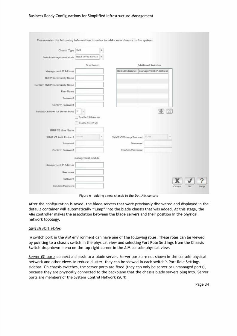
8/8/2019 Dell BRC for Simplified Infrastructure Management
http://slidepdf.com/reader/full/dell-brc-for-simplified-infrastructure-management 34/43
Business Ready Configurations for Simplified Infrastructure Management
Page 34
Figure 6 – Adding a new chassis to the Dell AIM console
After the configuration is saved, the blade servers that were previously discovered and displayed in the
default container will automatically “jump” into the blade chassis that was added. At this stage, the
AIM controller makes the association between the blade servers and their position in the physical
network topology.
Swi t ch Port Roles
A switch port in the AIM environment can have one of the following roles. These roles can be viewed
by pointing to a chassis switch in the physical view and selecting Port Role Settings from the Chassis
Switch drop-down menu on the top right corner in the AIM console physical view.
Server (S) ports connect a chassis to a blade server. Server ports are not shown in the console physical
network and other views to reduce clutter; they can be viewed in each switch’s Port Role Settings
sidebar. On chassis switches, the server ports are fixed (they can only be server or unmanaged ports),
because they are physically connected to the backplane that the chassis blade servers plug into. Server
ports are members of the System Control Network (SCN).

8/8/2019 Dell BRC for Simplified Infrastructure Management
http://slidepdf.com/reader/full/dell-brc-for-simplified-infrastructure-management 35/43
Business Ready Configurations for Simplified Infrastructure Management
Page 35
External (E) ports connect to networks outside the AIM environment. Any switch port that is not
configured as a server or unmanaged port is configured as an external port by default. External ports
are displayed at the side of chassis in the physical and other views, where cables can be connected or
disconnected from other switch ports or from external networks. If an external port is cabled on one
switch to the external port on another switch in the AIM environment, both ports are changed to
interconnect ports.
Interconnect (I) ports connect managed switches within the AIM environment. An interconnect port is
created in the console physical network view by cabling an external port on one switch to an external
port on another switch in the AIM environment that converts both ports to interconnect ports. If the
cable is disconnected from an interconnect port, it becomes an external port again.
Interconnect ports are members of all VLANs; their native VLAN is the sink VLAN that is VLAN 4005
(unless a different sink VLAN is specified during controller installation).
Unmanaged (U) ports are ports that AIM does not manage; they must be configured with the switch’s
own management tools. Unmanaged ports are not shown in the workspace. A cable or server must be
deleted if it is connected to a port before a switch port’s port role can be changed to unmanaged.
Convert ing t he ‘Read-Only’ swi t ches t o be ‘ Full y Managed’
When a switch management mode is Fully Managed the AIM controller can make changes to the switch
using a combination of SNMP and telnet. To convert a previously discovered switch, point to the switch
from the AIM console physical view and select Management Settings from the Chassis Switch drop
down menu. Change the Management Mode field to Fully Managed, and enter the switch user name
and password when prompted. Once this information is entered and the configuration is saved, the AIM
controller has the ability to make changes to the switch configuration which enables automated
network configuration that is one of the prerequisites for deploying this infrastructure.
Creat ing Basic Network Topologies
In this section, we will explore some basic capabilities of having the AIM controller manage the network
switches in the environment and introducing some new AIM terms. Virtual networks in an AIM-managed
environment behave as conventional networks in a data center, except that they’re built from virtual
LANs (VLANs) running over the physical NICs, switches, and cables, instead of those physical elements
themselves. Because these are virtual networks, it is easier for AIM to create and manage them when
compared to conventional networks. In order to build network topologies in an AIM environment,
switch to the Virtual view in the AIM console.
vSwitch - A vSwitch (Virtual Switch) is the virtual equivalent of a physical switch; a vSwitch is the
AIM term used to refer to a VLAN. vSwitches can be added using simple drag-and-drop operations in
the AIM console. Drag a vSwitch icon from the left sidebar on to the workspace. On the right
sidebar, the VLAN ID can be entered if desired. If left blank, the AIM controller will assign the next
available VLAN ID from the block of VLANs in the Controller-Assigned VLAN range. Once the
configuration is saved, a new VLAN is created in the environment, and can be viewed by logging
into the chassis switches and accessing the switch configuration.
vNIC – A vNIC is a Virtual NIC (Network Interface Card). The vNICs are configured on the persona,
and in the most basic configuration each vNIC will correspond to each physical NIC on the server
that is running the persona. A vNIC can be created by dragging a vNIC onto a persona in the AIM
console Virtual view. After the vNIC is created, the IP address for the interface can also be
assigned; this can also be accomplished during the set up process. AIM provides multiple options to
set IP addresses.
8/8/2019 Dell BRC for Simplified Infrastructure Management
http://slidepdf.com/reader/full/dell-brc-for-simplified-infrastructure-management 36/43
Business Ready Configurations for Simplified Infrastructure Management
Page 36
A simple network topology can be created by using the following steps:
1. Choose two running personas.
2. Drag a vNIC into each persona, and assign them static IP addresses in the same subnet. For
example, 192.168.0.10 and 192.168.0.20
3. Drag a vSwitch into the workspace.
4. Draw cables from both the vNICs to the vSwitch.
5. Save the configuration.
The topology can be tested in multiple ways. First, ping both IP address from each server. Next,
check the switch configuration and examine the VLAN membership of the switch ports connected to
the servers that are running the personas. The VLAN ID of the vSwitch that was created on both the
ports will be visible; deleting one of the cables and saving the configuration will automatically
update the switch configuration.
Phase 4
AIM Agent Inst all at ion
The Dell AIM solution includes an optional agent component that can be installed on the personas to
carry out some advanced functions, including Advanced Health Monitoring, OS side Virtual Networking,
and Workload Configuration and Management. In this section, we will see how the agent software can
be installed and how the various agent functions can be enabled.
Installing AIM agent software for Windows
Log into the server running the persona as the administrator. Mount the AIM software distribution for
Windows and run the executable – setup_persona.exe present in the root directory. When asked to
confirm the AIM agent software install on the server, click OK.
If a needed version of the NIC driver is not available, the installer will prompt for an update. The setup
application installs the AIM agent software in the C:\Scalent\persona directory. It then configures
and starts the persona agent service. If the firewall software is configured on the server, the persona
disables it; the persona can’t operate correctly with a local firewall running. If any services (such as
Apache or IIS) are installed on the persona, they should be configured to start after the persona agent
service.
Installing AIM agent software for Linux
Log in to the server running the persona as the root user. Mount the AIM software distribution for Linux
and execute the following command from the root directory of the distribution. The script installs theagent software.
# ./installPersona.sh
When the installation is complete, start the AIM service using the following command:
# service scalent start
8/8/2019 Dell BRC for Simplified Infrastructure Management
http://slidepdf.com/reader/full/dell-brc-for-simplified-infrastructure-management 37/43
Business Ready Configurations for Simplified Infrastructure Management
Page 37
Persona Net wor k Management
The AIM agent provides OS-side virtual networking capabilities. In the previous section, we briefly
discussed how vNICs (Virtual NICs) can be created on personas. If the agent is not installed, the number
of vNICs is limited to the number of physical NICs in the server. Multiple vNICs can be instantiated on a
single physical NIC.2
In order to create virtual NICs, ensure that the Networking Enabled persona property under thepersona drop-down menu is checked, and this can be done either from the AIM console catalog or
virtual view. Persona properties can be changed only when the persona is in a dormant state. If the
persona is running, it needs to be stopped first; however, vNICs can be added to personas, regardless of
whether they are running or dormant.
Workload Management
The AIM agent also provides workload configuration and management capabilities. The workload
configuration function defines the startup and shutdown of application-related services, and is referred
to as persona extensions. The extensions are external scripts that are automatically executed when
there is a transition in the persona state. Let us take an example of a persona running a Web server
workload. During the boot up process, a persona extension can be executed to automatically update
the load balancer routing table; details regarding workload management capabilities and persona
extensions are beyond the scope of this paper
Troubleshooting
Best Pract ices
Dell FlexAddress should not be used in conjunction with the Dell AIM solution. Refer to the “Operations
Topics” document for additional best practices.
Known Issues
vNICs with Windows 2003 and 10GbE networking
Description: When running iSCSI-booted Windows 2003 personas in a 10GbE environment, vNICs cannot
be created on the NICs used for booting and configured on the SCN.
Solution: If vNICs are needed in the environment, the server will need to have additional NICs that are
not used for booting up the persona; the vNICs can only be created on the additional NICs.
Basic Troubleshooting
The AIM support portal includes an extensive knowledgebase that can be accessed for a variety of
commonly encountered issues, as well as troubleshooting tips.
2 This feature of creating Virtual NICs is currently not available for Windows 2008 personas

8/8/2019 Dell BRC for Simplified Infrastructure Management
http://slidepdf.com/reader/full/dell-brc-for-simplified-infrastructure-management 38/43
Business Ready Configurations for Simplified Infrastructure Management
Page 38
ReferencesIntegrating Blade Solutions with EqualLogic SANshttp://www.dell.com/downloads/global/partnerdirect/apj/Integrating_Blades_to_EqualLogic_SAN.pdf
Deploying Pools and Tiered Storage in a PS Series SAN
http://www.equallogic.com/resourcecenter/assetview.aspx?id=5239
Deploying Thin Provisioning in a PS Series SAN
http://www.equallogic.com/resourcecenter/assetview.aspx?id=5245
Network Connection and Performance Guidelines
http://www.equallogic.com/resourcecenter/assetview.aspx?id=5311
Network Connection Guidelineshttp://www.equallogic.com/resourcecenter/assetview.aspx?id=5331
PS Series Array Network Performance Guidelineshttp://www.equallogic.com/resourcecenter/assetview.aspx?id=5229
Dell PowerConnect Switcheshttp://www.dell.com/powerconnect
Dell PowerConnect M8024 Product Pagehttp://www.dell.com/us/en/enterprise/networking/switch-powerconnect-m8024/pd.aspx?refid=switch-powerconnect-m8024&s=biz&cs=555
Dell PowerConnect 8024F Product Pagehttp://www.dell.com/us/en/enterprise/networking/switch-powerconnect-8024f/pd.aspx?refid=switch-powerconnect-8024f&s=biz&cs=555
Dell PowerConnect 80xx Command Line Interface Guide
http://support.dell.com/support/edocs/network/80xx/cli_ref/PDF/cli_ref.zip
Dell PowerConnect 80xx User's Guidehttp://support.dell.com/support/edocs/network/PC80xx/en/UG/PDF/ug.zip
AIM Support Portalhttp://www.scalent.com/support
AIM DocumentationCan be found on media shipped with solution or at http://www.scalent.com/support
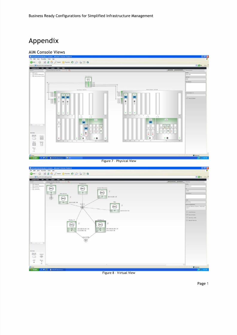
8/8/2019 Dell BRC for Simplified Infrastructure Management
http://slidepdf.com/reader/full/dell-brc-for-simplified-infrastructure-management 39/43
Business Ready Configurations for Simplified Infrastructure Management
Page 1
Appendix
AIM Console Views
Figure 7 – Physical View
Figure 8 – Virtual View
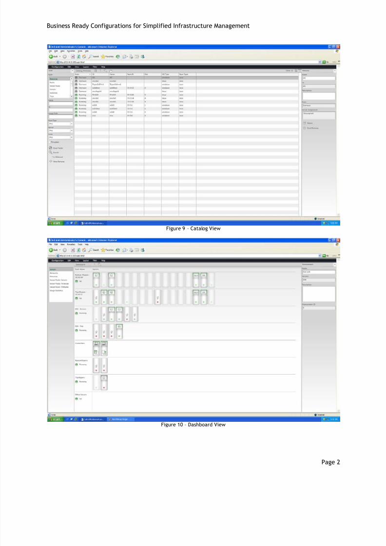
8/8/2019 Dell BRC for Simplified Infrastructure Management
http://slidepdf.com/reader/full/dell-brc-for-simplified-infrastructure-management 40/43
Business Ready Configurations for Simplified Infrastructure Management
Page 2
Figure 9 – Catalog View
Figure 10 – Dashboard View

8/8/2019 Dell BRC for Simplified Infrastructure Management
http://slidepdf.com/reader/full/dell-brc-for-simplified-infrastructure-management 41/43
Business Ready Configurations for Simplified Infrastructure Management
Page 3
Configuring Dell PowerConnect Ethernet switchesThe PowerConnect M8024 switch has 24 gigabit Ethernet ports, xg1 through xg24. Ports xg1 through
xg16 connect to the blade servers inserted in the chassis’ 16 blade server slots. Port xg17 through xg24
correspond to the switch’s 8 external ports used to connect to other switches, or to devices outside the
AIM environment. By default, AIM reserves the first external port (xg17) for managing the switch. In
this configuration, we will configure ports xg17 and xg18 in an aggregated link for improved bandwidthand resiliency. Follow the steps below to configure the chassis switch module.
The PowerConnect 8024F switch needs to be configured in a similar manner, but the ports are not
assigned to a particular function. The ports connecting the switches together need a similar aggregated
link configured, and the SCN (VLAN 4004) needs to be added to all interconnect ports.
1. Disconnect all cables from the switch’s external ports
2. Establish a telnet connection to the CMC and log in as the ‘root’ user.
3. Connect to the switch module from the CMC. In the following command, replace x with the
number of the switch to connect to:
$ connect switch-x
connect: acquiring remote port.
Connected to remote port.
Escape character is '^\'.
The switch displays a prompt, typically console> 4. Check that a supported firmware version is running. If not, install a supported version of the
firmware as described in the documentation that came with the chassis.
5. Enter ‘enable’ mode to change switch configuration.
console> en
console#
6. Reset the switch to factory default settings.
console# delete startup-config
Delete startup-config? [Y/N](N): y
Startup file was deleted
console# reload
You haven't saved your changes. Are you sure you want to continue
(y/n) [n] ? y
This command will reset the whole system and disconnect your
current
session. Do you want to continue (y/n) [n] ? y
7. Reconnect to the switch and when prompted, do not run the setup wizard.8. Enter Configuration mode.
console> en
console#
console# configure
console(config)#
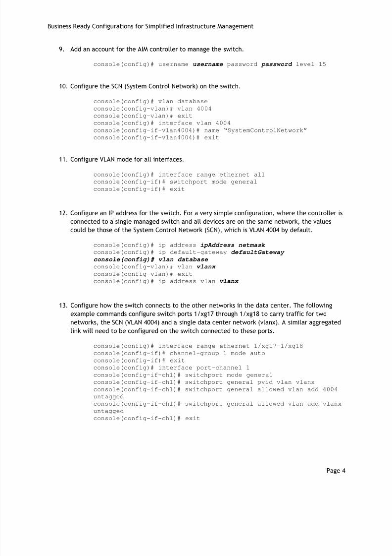
8/8/2019 Dell BRC for Simplified Infrastructure Management
http://slidepdf.com/reader/full/dell-brc-for-simplified-infrastructure-management 42/43
Business Ready Configurations for Simplified Infrastructure Management
Page 4
9. Add an account for the AIM controller to manage the switch.
console(config)# username username password password level 15
10. Configure the SCN (System Control Network) on the switch.
console(config)# vlan database
console(config-vlan)# vlan 4004
console(config-vlan)# exit
console(config)# interface vlan 4004
console(config-if-vlan4004)# name “SystemControlNetwork”
console(config-if-vlan4004)# exit
11. Configure VLAN mode for all interfaces.
console(config)# interface range ethernet all
console(config-if)# switchport mode general
console(config-if)# exit
12. Configure an IP address for the switch. For a very simple configuration, where the controller is
connected to a single managed switch and all devices are on the same network, the values
could be those of the System Control Network (SCN), which is VLAN 4004 by default.
console(config)# ip address ipAddress netmask
console(config)# ip default-gateway defaultGateway
console(config)# vlan database
console(config-vlan)# vlan vlanx
console(config-vlan)# exit
console(config)# ip address vlan vlanx
13. Configure how the switch connects to the other networks in the data center. The following
example commands configure switch ports 1/xg17 through 1/xg18 to carry traffic for two
networks, the SCN (VLAN 4004) and a single data center network (vlanx). A similar aggregated
link will need to be configured on the switch connected to these ports.
console(config)# interface range ethernet 1/xg17-1/xg18
console(config-if)# channel-group 1 mode auto
console(config-if)# exit
console(config)# interface port-channel 1
console(config-if-ch1)# switchport mode general
console(config-if-ch1)# switchport general pvid vlan vlanx
console(config-if-ch1)# switchport general allowed vlan add 4004untagged
console(config-if-ch1)# switchport general allowed vlan add vlanx
untagged
console(config-if-ch1)# exit

8/8/2019 Dell BRC for Simplified Infrastructure Management
http://slidepdf.com/reader/full/dell-brc-for-simplified-infrastructure-management 43/43
Business Ready Configurations for Simplified Infrastructure Management
14. Configure the switch port that corresponds to the chassis slot the controller blade server will
connect to. In the following commands, replace controllerPort with the switch port that
the controller will connect to.
console(config)# interface ethernet controllerPort
console(config-if-port)# switchport general pvid 4004
console(config-if-port)# switchport general allowed vlan add 4004console(config-if-port)# exit
console(config)# exit
15. Add a read-write SNMP community for use by the AIM controller.
console(config)# snmp-server community aim rw
16. Save the switch configuration.
console# copy running-config startup-config
17. Restart the switch.
console# reload
Connect the switch’s external ports (xg17-xg18) to the data center network.