Delixi Industrial-control Product Type Selection Manual · 2017-03-24 · Delixi Industrial-control...
13
Delixi Industrial-control Product Type Selection Manual Delixi Inverters, Your Only Choice Inverter Soft Starter Brake Unit Accessories CDI-E180-series Vector Control Inverter CDI-E100-series Economical-type Inverter CDI-E102-series Mini Inverter CDI-EM60-series Single-phase Inverter CDRA Device-type Soft Starter CDRA Comprehensive-protection Soft Starter CD-BR Energy-consumption Brake Unit CDI-E-series Multi-functional Expansion Card Distributor Contact Information: Hangzhou Delixi Group Co., Ltd. Address: No.8, Economic Plot, Zhuantang Science & Technology Park, Zhuantang Street, Xihu District, Hangzhou, Zhejiang Hotline: 400-188-8155 Website: //www.delixidrive.com Postal Code: 310023 Fax: 0571-85223288; 85243783 Version: 2015.0101 Our products and the manual contents are subject to change without prior notice.
Transcript of Delixi Industrial-control Product Type Selection Manual · 2017-03-24 · Delixi Industrial-control...

Delixi Industrial-control ProductType Selection Manual
Delixi Inverters, Your Only Choice
Inverter
Soft Starter
Brake Unit
Accessories
CDI-E180-series Vector Control Inverter
CDI-E100-series Economical-type Inverter
CDI-E102-series Mini Inverter
CDI-EM60-series Single-phase Inverter
CDRA Device-type Soft Starter
CDRA Comprehensive-protection Soft Starter
CD-BR Energy-consumption Brake Unit
CDI-E-series Multi-functional Expansion Card
Distributor Contact Information:
Hangzhou Delixi Group Co., Ltd.Address: No.8, Economic Plot, Zhuantang Science & Technology Park,
Zhuantang Street, Xihu District, Hangzhou, Zhejiang
Hotline: 400-188-8155
Website: //www.delixidrive.com
Postal Code: 310023
Fax: 0571-85223288; 85243783
Version: 2015.0101 Our products and the manual contents are subject to change without prior notice.

Contents
01 Company Profile
03 CDI-E180-series Vector Control Inverter
03 CDI-E100-series Economical-type Inverter
04 CDI-E102-series Mini Inverter
04 CDI-EM60-series Single-phase Inverter
05 Soft Starter
05 Brake Unit
06 E-series Inverter Technical Standard
08 E-series Inverter Keyboard and Naming Rules
09 E-series Inverter Wiring Diagram
10 E100/E102-series External Dimensions
11 E180-series External Dimensions
12 EM60-series External Dimensions
13 Accessories
15 CDRA-series Full-digital Intelligent Soft Starter for AC Motors
19 Energy-consumption Brake Unit and Energy-consumption Brake Resistor

Com
pany Profile
Company Profile
Our Mission Our Vision Core ValueDevoted to the World, Create the Future
To be a world-famous company with leading core technology and outstanding comprehensive strength
Excellence, Efficiency, Cooperation, Responsibility
Awards
Patents
ProductCertification
Utility Model Patent
Software Copyright
WIT Assessment
Business culture &
Patents

Inverters: CDI-E180-series Vector Control Inverter
Inverters: CDI-E100-series Economical-type Inverter
AC 3PH 340V-420V 0.75-630kWAC 3PH 200V-240V 0.4-30kW
AC 1PH 200V-240V, 0.4-2.2kWAC 3PH 200V-240V, 0.4-2.2kWAC 3PH 340V-420V, 0.75-22kW
Introduction
Technical Characteristics
Applications
Accessories
Introduction
Technical Characteristics
Applications
Accessories
The CDI-E180-series inverter is a stable and versatile high-performance vector control inverter with optimum control modes such as SVC, V/F control and VC, and is widely used in situations with demanding requirements for speed control precision, torque respond speed and low-frequency output torque.
Excellent Performance
Strong Function and Low Cost
Easy Operation
Flexible Type Selection
Due to the new vector control algorithm, the inverter features large start torque, quick torque response and high control precision to further improve the efficiency of the motor.
The large number of internal function modules such as timer, virtual time-delay relay and math operation modules are as a whole equivalent to an additional small PLC, so that the cost is significantly reduced.
A special-purpose function is embedded, and the conversion between the special-purpose function and the common function is available through one function code, for the convenience of type selection and flexibility in use.
The 15kW or below types have standard internal brake units, the 18.5-30kW types can have optional internal brake units, and the 37kW above types shall be connected with external brake units. The 11kW, 15 kW, 200 kW or above types have standard DC inductors, and 18.5-55kW types can have optional DC inductors.
Electric power, textile and chemical fiber, building materials, oil industry, chemical industry, metallurgy, municipal facilities, paper-making, food & beverage and tobacco.
E180-I/O expansion card; E180-PG coder expansion card; E180-485 communication expansion card; E180-DP communication expansion card.E180-ZS injection molding machine expansion card; E180-WSP constant pressure water supply expansion card.
The CDI-E100-series inverter is a general-purpose low-power inverter with optimum control modes including SVC and V/F control, stable performance, diversified functions, high cost performance, optimum structure and elegant appearance.
Optimum structure and elegant appearance; can be installed through both slides and holes; easy to use.Compact Structure
Reliable Small Integrated ModuleReliable small integrated module to ensure good quality and performance at a lower price.
Integrated Communication ModuleStandard internal RS-485 communication module which enables standard MODBUS-RTU communication; through such a module, one host computer can communicate with several inverters simultaneously and quickly with perfect anti-interference performance.
Flexible Type SelectionThe 15kW or below types have standard internal brake units, and the 18.5-22kW types can have optional internal brake units.The 11kW, 15 kW types have standard DC inductors, and 18.5-22kW types can have optional DC inductors.
Mainly applies to low-power non-VC situations with demanding requirements for input/output.Carving machine, textile machine, glass-making machine and dyeing machine.
External keyboard, extension cord.
Inverters: CD
I-E180-series V
ector Control Inverter &
Inverters: C
DI-E
100-series Econom
ical-type Inverter
Inverters: CD
I-E102-series M
ini Inverter &
Inverters: CD
I-EM
60-series Single-phase Inverter
Inverters: CDI-E102-series Mini Inverter
Inverters: CDI-EM60-series Single-phase Inverter
AC 1PH 200V-240V, 0.4-2.2kWAC 3PH 200V-240V, 0.4-2.2kWAC 3PH 340V-420V, 0.75-22kW
AC 1PH 200V-240V, 0.4-2.2kW
Introduction
Technical Characteristics
Applications
Accessories
The CDI-E102-series inverter is a classic-type low-power inverter with optimum SVC and V/F control, stable performance and simplified functions. It reserves the configuration most-frequently used by users, and is more cost-effective.
Optimized configuration according to the functions most-frequently used by users, so as to reduce resource waste, improve cost performance and competitiveness.
Simplified Functions and More Cost-effective
Compact StructureOptimum structure and elegant appearance; can be installed through both slides and holes; easy to use.
Flexible Type SelectionThe 15kW or below types have standard internal brake units, and the 18.5-22kW types can have optional internal brake units.The 11kW, 15 kW types have standard DC inductors, and 18.5-22kW types can have optional DC inductors.
Mainly applies to low-power non-VC situations with demanding requirements for input/output.Die-cutting machine, carving machine, textile machine, glass-making machine and dyeing machine.
External keyboard, extension cord, E102-485 communication expansion card.
Introduction
Technical Characteristics
Applications
Accessories
The CDI-EM60-series inverter is a mini-type low-power single-phase inverter with optimum SVC and V/F control, stable performance and simplified functions. It reserves the configuration most-frequently used by users, and can be extended with several I/O and communication interfaces.
Small size and easy operation; Embedded with DC brake function and can have optional external brake unit; Accuracy of stop position.Separate keyboard that supports hot plug and can be pulled out to a distance of 50m at most; a copy keyboard with parameter control is optional.Extensible RS485 communication interface which enables standard MODBUS-RTU communication and can be compatible with a variety of host computers.Long service-life with a controllable fan; the AVR (Automatic Voltage Regulation) function ensures large output torque in case of low input voltage.Multiple protection functions to ensure safe and reliable operation of the motor.All standard products have been treated with conformal coatings.Air-duct isolated by windshields to ensure good thermal dissipation and thus significantly improved adaption to the environment.
Mainly applies to low-power non-VC situations with demanding requirements for input/output.Die-cutting machine, carving machine, textile machine, glass-making machine, dyeing machine, book sewer, automatic production line and food machine.
EM60-IO expansion card, EM60-485 communication expansion card, internal brake unit.

Soft Start Series: CDRA Device-type/Comprehensive-protection Soft Starter (Power Range: 11-600kW)
IntroductionThe Delixi Soft Starter is a motor control equipment featuring soft start, soft parking, light-loading and energy-saving as well as multi-functional protection. The soft starter enables smooth and impact-less start during the whole start process, and the parameters such as current limit and start time can be adjusted according to the characteristics of the motor load. It can be divided into two categories: the Device-type Soft Starter and the Comprehensive-protection Soft Starter.Soft Start Series: C
DR
A D
evice-type/Com
prehensive-protection Soft Starter &
Brake U
nit Series: CD
I-BR
Energy-consum
ption Brake U
nit
Brake Unit Series: CDI-BR Energy-consumption Brake Unit
Applications
Product Characteristics
The soft starter can be applied to motors in crushers, compressors, transmission, pumps and air blowers.
A Variety of Start Modes: Current limit soft start, ramp voltage soft start, ramp voltage + current limit soft start.Highly Reliable: A high-performance microprocessor performs digital processing of the signals in the control system.Strong Anti-interference Capability: Easy-tuning, optoelectronic-isolator-based signal transmission in the processing unit, different anti-noise levels.Optimum Structure: Unique compact structure, double-layer shell consisting of plastic upper layer and metal lower layer to meet the aesthetic and durability requirements.Motor Protection: Multi-functional protection (e.g. in case of over-current, input/output default phase, SCR short-circuit and overheat).Easy Maintenance: Four-digit signal monitoring system to monitor the operation of the system equipments in 24 hours and to offer quick fault diagnosis.
Introduction
Applications
Product Characteristics
Delixi Brake Unit is mainly designed to release the regenerated power during the speed adjustment of the motor through the brake resistor. It effectively overcomes the disadvantages of low brake speed and small brake torque (≤20% rated torque) of conventional inverters, which makes it extremely suitable for quick brake situations.
The brake unit is applicable to high rise elevators, escalators, coal mine cars and winches, hoisting equipments, oil field pumping units, lifts, cranes, centrifuges and winding machines.
Improved short-circuit, overheat and over-current protection.A complete range of products with voltage from 220V to 690V.Set the brake-unit parameters on the host panel.Value adjustment for the multi-shift brake voltage valve, large brake torque, good braking effect.A variety of optional machine types, brake-unit parallel operation is available though the DC bus-bar without capacity limits.Small size and space-saving.
E-series Inverter Technical Standards
Item
E-series Inverter Technical Standards
Specifications
Con
trol
Bas
ic T
ype
Func
tion
Control Mode
Frequency Precision
V/F Curve
Overload Capacity
Start Torque
Speed Adjustment Range
Steady Speed Precision
Torque Precision
Torque Compensation
Operating Mode
Frequency Source
Torque Source
Acceleration and Deceleration Time
Emergency Stop
Multi-speed
Simple PLC
Inching Control
Rotating-speed Track
Length and Distance Control
Counting
Swing Frequency
Internal PID
AVR
DC Brake
Slip Compensation
Hopping Frequency
Droop Function
Timing
V/F control
Open-loop Vector Control (SVC)
Vector Control (VC) (Not applicable to E100/E102/EM60 series)
Digital: 0.02%Analog: 0.1%
Linear, square root, any V/F
G-type: 150% rated current for 60s; 180% rated current for 3s
P-type: 120% rated current for 60s; 150% rated current for 3s
G-type: 0.5Hz/150% (SVC); 0Hz/180% (VC)
1:100 (SVC)
0.5% (SVC)
5% (VC)
1:1000 (VC)
0.02% (VC)
Manual torque compensation (0.10%-30.0%); Automatic torque compensation
Key-board, terminal, RS485 communication
14 main sources, 14 auxiliary sources. Easy switch between different modes.Diversified input modes for every source: keyboard potentiometer, external analog, digital setting, pulse frequency, multi-speed, simple PLC, communication, computing results, etc.
14 torque sources, including digital setting, external analog, pulse setting, multi-order, communication, computing results, etc.
4 groups of lines (can be switched through the option terminals); S Curve 1, S Curve 2
Interrupt the output instantaneously
16-shift speeds at most; can be switched by different combination of order terminals
Inching frequency and inching acceleration/deceleration time can be set separately; Inching can be prioritized in process.
Continuous operation of 16-shift speeds; the acceleration/deceleration time, operating time and frequency source for every shift can be set separately
Track the start speed and operating speed of the inverter’s load
Length and distance control through pulse inputs
Counting through pulse inputs
For winding machines in the textile industry
Closed-loop process control system is available
Ensure constant output in case of fluctuating grid voltage
Quick and stable parking is available
Compensate the slip deviation due to increased load
Prevent resonance with the load
Balance the load rate of different motors which drive the same load
Automatic stop at a given time

E-series Inverter Technical Standard
E-series Inverter Technical Standard
E-series Inverter K
eyboard
Item
Internal Virtual Time-Delay Relay
E-series Inverter Keyboard
Specifications
Simple logic programming for the multi-functional output terminals and the digital input terminals. The logic results can be equivalent to the digital input terminal function, and can be output through the multi-functional output terminals
Two internal timers to collect timing input signals and to output timing signals.The two timers can be used separately or together
Internal Timer
Internal Math Operation Module
Enh
ance
d Fu
nctio
nC
omm
unic
atio
nC
oder
Mot
orD
ispl
ayPr
otec
tion
Env
iron
men
t
E100
E102/E180/EM60
E100
EM60
E102
E180
E100/E102
E180
Operation Information
Fault Information
Inverter Protection
Inverter Alarm
Instantaneous Power Down
Ambient Temperature
Storage Temperature
Ambient Humidity
Altitude/Vibration
Working Place
Cooling
One internal 4-way math operation module for elementary arithmetic operations, numerical magnitude judgment and integral operation
The control panel has a RS485 communication interface which supports standard MODBUS-RTU protocol
The control panel does not have a RS485 communication interface, and an external 485 communication expansion card shall be connected. Support standard MODBUS-RTU protocol. The E180-series also support standard PROFIBUS-DP protocol (through an external E180-DP expansion card).
The coder can be connected directly through the DI5 and DI6 terminals on the control panel, and simple closed-loop control is available through PID control. Such connection is used in undemanding situations.
The control panel does not have any interface for the coder, and a one-way high-speed pulser can be extended (through DI6).
The control panel only has one coder interface (DI6).
The control panel does not have any coder interface, and an external coder expansion card is necessary. The inverter supports ABZ incremental coder, UVW incremental coder and resolver. Such connection enables high-performance VC, and can be used in situations with demanding control precision requirements.
Only for asynchronous motors
For asynchronous motors and synchronous motors
Given frequency, output frequency, output voltage, busbar voltage, input signal, feedback value, module temperature, and synchronous speed of the motor. At most 32 parameters can be displayed in cycle through the “>>” key.
In the fault protection mode, three pieces of history fault information can be saved. Every piece includes the frequency, current, busbar voltage and I/O terminal status when the fault takes place.
Over-current, over-voltage, module fault protection, under-voltage, overheat, overload, external fault protection, EEPROM fault protection, ground protection, and default phase
Locked-rotor protection, overload alarm
Less than 15 ms: continuous operationMore than 15ms: automatic restart
-10℃~ 40℃
-10℃~ 40℃
Max. 90% RH (No condensation)
Below 1000m; below 0.6g
No corrosive gas, inflammable gas, oil mist or dust
Force-air cooling
E100/E102-series
In the parameter setting mode, the key is used to read and save the parameter settings.
1. Switch between display modes 2. Cancel data changes
1. Select functional code2. Data increase/decrease setting3. Increase/decrease setting for a given frequency
Nameplate Data and Naming Rules
Display operation status and unit
1. Display the setting for each functional code2. Output the watch value
Multi-functional Key
Potentiometer, frequency adjustment1. In monitoring mode, the key is used to scroll-display the data2. When parameters are selected and set, the key is used to move to the digit to be modified.
Stop/Reset key
Run Key
Nameplate Data: e.g. CDI-E180G055T4BHL
Product Series No.
Company code
E100-seriesE102-seriesE180-seriesEM60-series
Product CategoryG: For general-purposeP: For air blowers and water pumps
Applicable motor power
None: No internal DC inductorL: Internal DC inductor
None: LED keyboardH: LCD keyboard
None: No internal brake unitB: Internal brake unit
Voltage Class (Rated voltage)S2: Single-phase 220V, 50/60HzT2: Three-phase 220V, 50/60HzT4: Three-phase 380V, 50/60Hz
Model:
Input:
Output:

E-series Inverter Wiring Diagram
E-series Inverter W
iring Diagram
E100/E102-series External Dimensions
CDI-E100-seriesFrequency Converter
Brake Resistor
Circuit Breaker
The internal 24V power supply is used by default
Digital Input Term
inals
Digital Input 1
Digital Input 2
Digital Input 3
Digital Input 4
Digital Input 5
Digital Input 6
Common TerminalCOM (Common Digital Signal Terminal)
External Potentiometer(1K 1/2W)
+10V (Analog Signal Power)
VF1 (Analog Input 1)
VF2 (Analog Input 2)
GND Analog Grounding
RS485CommunicationInterface
Three-phase Asynchronous Motor
Analog Output 1
Analog Output 2
0 ~ 10V/4 ~ 20mA
0 ~ 10V/4 ~ 20mA
Multi-functional Open Collector Output
YO (P2.1.20=1):
DC48V 50mA
Pulse OutputFMP (P2.1.20=0):
0.01kHz ~ 100.00kHz
Relay Output 1Below AC250V 3ABelow DC30V 3A
Relay Output 2Below AC250V 3ABelow DC30V 3A
The digital signal power supply can offer 24V external power with Max. output current of 200mA
(Note: The E102-series inverter is not configured with red terminals)
Application: E100/E102-series with three-phase 220V power supplyApplication: E100/E102-series with three-phase 380V power supply
Application: E180-series with three-phase 380V power supplyApplication: E180-series with three-phase 220V power supply
CDI-E100-series Frequency Converter
Brake Resistor
Circuit Breaker
The internal 24V power supply is used by default
Digital Input 1
Digital Input 2
Digital Input 3
Digital Input 4
Digital Input 5
Digital Input 6
Common Terminal
Digital Input Term
inals
COM (Common Digital Signal Terminal)
External Potentiometer(1K 1/2W)
+10V (Analog Signal Power)
VF1 (Analog Input 1)
VF2 (Analog Input 2)
GND Analog Grounding
RS485CommunicationInterface
Three-phase Asynchronous Motor
Analog Output 10 ~ 10V/4 ~ 20mA
Analog Output 2
0 ~ 10V/4 ~ 20mA
Multi-functional Open Collector Output
YO (P2.1.20=1):
DC48V 50mA
Pulse OutputFMP (P2.1.20=0):
0.01kHz ~ 100.00kHz
Relay Output 1Below AC250V 3ABelow DC30V 3A
Relay Output 2Below AC250V 3ABelow DC30V 3A
The digital signal power supply can offer 24V external power with Max. output current of 200mA
Application: E100/E102-series withsingle-phase 220V power supply
(Note: The E102-series inverter is not configured with red terminals)
CDI-E180-seriesFrequency Converter
DC Inductor
Brake Unit
Brake Resistor
Circuit Breaker
The internal 24V power supply is used by default
Digital Input 1
Digital Input 2
Digital Input 3
Digital Input 4
Digital Input 5
Digital Input 6
Common TerminalCOM (Common Digital Signal Terminal)
External Potentiometer(1K 1/2W)
+10V (Analog Signal Power)
VF1 (Analog Input 1)
VF2 (Analog Input 2)
GND Analog Grounding
Coder ExpansionCard Interface
Three-phase Asynchronous Motor
Analog Output 1
Analog Output 2
0 ~ 10V/4 ~ 20mA
0 ~ 10V/4 ~ 20mA
Multi-functional Open Collector Output
YO (P2.1.20=1):
DC48V 50mA
Pulse OutputFMP (P2.1.20=0):
0.01kHz ~ 100.00kHz
Relay Output 1Below AC250V 3ABelow DC30V 3A
Relay Output 2Below AC250V 3ABelow DC30V 3A
The digital signal power supply can offer 24V external power with Max. output current of 200mA
I/O Communication Expansion Card Interface
Digital Input Term
inals
Circuit Breaker
Brake Resistor
Three-phase Asynchronous Motor
Digital Input Term
inals
Digital Input 1
Digital Input 2
Digital Input 3
Digital Input 4
Common Terminal
CDI-EM60-seriesFrequency Converter
External Potentiometer(1K 1/2W)
Expansion Card Interface
(Common DigitalSignal Terminal)
(Analog Signal Power)
(Analog Input 1)
(Analog Grounding)
Analog Output 10 ~ 10V/4 ~ 20mA
Multi-functional Relay Output T1Below AC250V 3ABelow DC30V 1A
The digital signal power supply can offer 24V external power with Max. output current of 200mA
Application: EM60-series with single-phase220V power supply, 0.4-2.2kW
Type 1
Type 2
Type 3
Note: The external dimensions of E102-series are the same as that of E100-series.
Model
Model
Model
Dimension Unit: Millimeter (mm)
Dimension Unit: Millimeter (mm)
Dimension Unit: Millimeter (mm)
CD
IE100/E
102-series External D
imensions
E180-series External Dimensions
E180-series E
xternal Dim
ensions
Type 1
Type 2
Type 3
Model
Model
Model
Dimension Unit: Millimeter (mm)
Dimension Unit: Millimeter (mm)
Dimension Unit: Millimeter (mm)
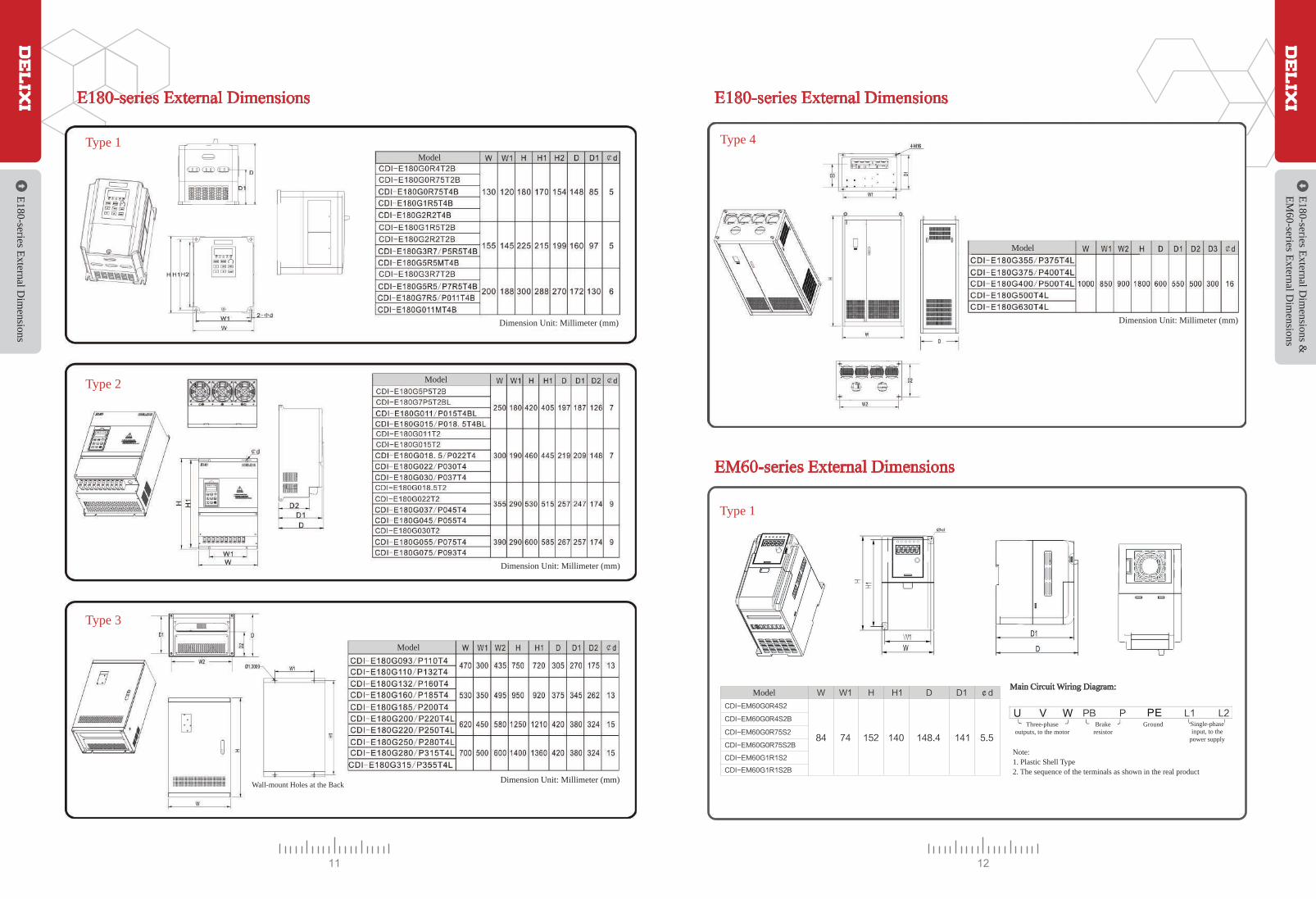
Type 4
E180-series External Dimensions
Type 1
Dimension Unit: Millimeter (mm)
EM60-series External Dimensions
E180-series E
xternal Dim
ensions &
EM
60-series External D
imensions
Wall-mount Holes at the Back
Model
Model
Note:1. Plastic Shell Type2. The sequence of the terminals as shown in the real product
Three-phaseoutputs, to the motor
Brakeresistor
Ground Single-phaseinput, to the
power supply
Main Circuit Wiring Diagram:

EM60-series External Dimensions
EM
60-series External D
imensions
Model
Note:1. Plastic Shell Type2. The sequence of the terminals as shown in the real product
Single-phaseinput, to the
power supply
Ground Brakeresistor
Three-phaseoutputs, tothe motor
Main Circuit Wiring Diagram:
Accessories for E-series
Accessories: M
ulti-functional Expansion C
ard
Accessories: Multi-functional Expansion Card
Type 2
E-series External Keyboard Dimensionsand Installation Holes
E100/E102-seriesLED external keyboard
E180-seriesLED small external keyboard
EM60-seriesLED small external keyboard
E180-seriesChinese-language large external keyboard
E180-seriesChinese-language small external keyboard
E180-seriesLED large external keyboard
Model Description Model Description
E180-IO1 Expansion Card4-way digital input (DI7-DI10)1-way analog input (VF3)2-way multi-functional open collector output (YO1, YO2)RS-485 communication interface (standard MODBUS-RTU protocol)E180-IO1
E180-IO2
E180-PG1
E180-PG2
E180-PG3
E180-PG4
E180-485
E180-IO2 Expansion Card4-way digital input (DI7-DI10)1-way analog input (VF3)2-way multi-functional open collector output (YO1, YO2)
E180 Coder Expansion Card 1A/B/Z deferential inputNo frequency division outputMax. Rate: 100kHzInput deferential signal amplitude: ≤7V
E180 Coder Expansion Card 2A/B/Z/U/V/W deferential inputNo frequency division outputMax. Rate: 100kHzInput deferential signal amplitude: ≤7V
E180 Coder Expansion Card 3A/B/Z open collector inputMax. Rate: 100kHz
E180 Resolver Expansion Card10kHz 7VRMS stimulus output12-digit resolution
No frequency division output
E180 Communication Expansion CardStandard MODBUS-RTU protocol
E102-485
E180-DP
E180-ZS
E180-WSP
EM60-IO
EM60-485
E102 Communication Expansion CardStandard MODBUS-RTU protocol
E180 PROFIBUS Expansion CardStandard PROFIBUS-DP protocolOptional only for 3.7kW or above typesNote: The expansion card E180-DP only applies to models with “DP” endings, e.g. ModelCDI-E180G3R7/P5R5T4B(DP)
E180 Injection Molding Machine Expansion Card2-way digital input (DI7-DI8)2-way analog conversion
E180 Water Supply Expansion Card4 main pumps + 1 auxiliary pump automatic controlPressure control for 8 intervals: any pressure can be set and ON/OFF timing is available within every intervalSleep function and the auxiliary pump to reduce energy consumption and prolong service lifeNote: Only 5.5kW or above types support rapid configuration
EM60-IO Expansion Card2-way digital input (DI5, DI6)1-way analog input (VF2)1-way analog output (FM2)
EM60 Communication Expansion CardSG+: 485 communication positive signal terminalSG-: 485 communication negative signal terminalMODBUS-RTU protocol

CDRA Series Full-digital Intelligent Soft Starter for AC Motors
CD
RA
Series Full-digital Intelligent Soft Starter for AC
Motors
The CDRA-series Full-digital Intelligent Soft Starter for AC Motors is new advanced-level start equipment featuring electric & electronic technology, micro-processing technology and modern control theory. It enables effective control of start current for asynchronous motors, and is a desired alternative to reduced-voltage starting equipments featuring star-delta conversion starting and self-coupling transformer starting. Furthermore, the soft starter has a variety of control modes through keyboard, external terminals or host computer, as well as output functions such as fault relay output, multi-functional relay output and analog output, so as to be flexible to play a role in the system.
Technical Standard
Ope
ratio
n
Operation Control Mode Keyboard/External Terminals/RS485 Communication
Prot
ectio
nD
ispl
ayW
orki
ng C
ondi
tions
Env
iron
men
t
Cooling
Start Mode
Start/Stop Time
Start Delay
Emergency Stop
Current Limit
Start Voltage
Light-load Control
Restart
Fault Output
Multi-functional Relay Output
Analog Output
Soft Starter Protection
Soft Starter Alarming
Key
boar
d
Operation Information
Parameter Protection
Type
Rated Insulation Voltage
Degree of Protection
Ambient Temperature
Storage Temperature
Ambient Humidity
Altitude/Vibration
Working Place
Current Limit/ Voltage/ Heavy-load
Digital Settings
Digital Settings
Interrupt the output of the soft starter
Start current below this value in the current limit and heavy-load modes
Start voltage can be set digitally in the voltage mode
Belt tripping can be detected
Restart automatically after stopped due to fault
Contact output: < AC 250V 5A; < DC 30V 5A
Start delay, start, operation, stop, complete stop, restart
0-20mA/ 4-20mA, optional
Over-current, overload, overheat, three-phase imbalance, default phase, light-load, external fault
Emergency stop, light-load, restart
Ready, start delay, start, operation, stop, fault alarm
Protect the parameters from being altered
AC-53b
660V Rated Impact-withstanding Voltage: 4kV
CDRA011T4~CDRA055T4: IP20
CDRA075T4~CDRA600T4: IP00
-10℃ ~ 40℃
-20℃ ~ 65℃
90% RH at most (No condensation)
< 1000m;< 5.9m/s2 (=0.6g)
No corrosive gas, inflammable gas, oil mist, or dust
Natural Cooling
CDRA-series Soft Starter Models
CD
RA
-series Soft Starter Models
ModelRated Power
(kW)Rated Current
(A)Circuit Breaker
(QF)Bypass Contactor
(KM) Primary Line
6mm Cable
30*3mm Copper Bar
30*3mm Copper Bar
30*4mm Copper Bar
30*4mm Copper Bar
40*4mm Copper Bar
40*5mm Copper Bar
40*5mm Copper Bar
50*5mm Copper Bar
50*5mm Copper Bar
50*5mm Copper Bar
50*5mm Copper Bar
10mm Cable
10mm Cable
16mm Cable
25mm Cable
35mm Cable
35mm Cable
35mm Cable
35mm Cable
CDRA011T4
CDRA015T4
CDRA018T4
CDRA022T4
CDRA030T4
CDRA037T4
CDRA045T4
CDRA055T4
CDRA075T4
CDRA093T4
CDRA110T4
CDRA132T4
CDRA160T4
CDRA200T4
CDRA250T4
CDRA320T4
CDRA400T4
CDRA450T4
CDRA500T4
CDRA600T4
11
15
18.5
22
30
37
45
55
75
93
110
132
160
200
250
320
400
450
500
600
25
32
37
45
60
75
90
110
152
176
210
253
300
380
480
600
750
892
930
1100
CJ20-25
CJ20-40
CJ20-40
CJ20-63
CJ20-63
CJ20-100
CJ20-100
CJ20-160
CJ20-160
CJ20-250
CJ20-250
CJ20-400
CJ20-400
CJ20-400
CJ20-630
CJ40-800
CJ40-1000
CJ40-1000
CJ40-1000
CJ40-1000
CDM1-63L/32
CDM1-63L/40
CDM1-63L/50
CDM1-63L/63
CDM1-100L/80
CDM1-100L/100
CDM1-225L/125
CDM1-225L/160
CDM1-225L/180
CDM1-225L/200
CDM1-400L/250
CDM1-400L/315
CDM1-400L/350
CDM1-400L/400
CDM1-630L/630
CDM1-800H/700
CDM1-800H/800
CDM1-1250/1000
CDM1-1250/1250
CDM1-1250/1250

CDRA-series Soft Starter External and Installation Dimensions
CD
RA
-series Soft Starter External and Installation D
imensions
CD
RA
-series Soft Starter External and Installation D
imensions
CDRA-series Soft Starter External and Installation Dimensions
Model
Dimension Unit: Millimeter (mm)
Model
Dimension Unit: Millimeter (mm)
Model
Dimension Unit: Millimeter (mm)
Model
Dimension Unit: Millimeter (mm)

CDI-E100G0R75T4B
CDI-E100G1R5T2B
CDI-E100G2R2T4B
CDI-E100G3R7T4B
CDI-E100G5R5/P7R5T4B
CDI-E100G7R5/P0R11T4B
CDI-E100G011/P015T4BL
CDI-E100G015/P018.5T4BL
CDI-E100G0185/P022T4
CDI-E100G022T4
Internal, Max. Current of 8A
Internal, Max. Current of 8A
Internal, Max. Current of 15A
Internal, Max. Current of 25A
CDI-E100G0R4T2B
CDI-E100G0R75T2B
CDI-E100G1R5T2B
CDI-E100G2R2T2B
80
160
250
400
400
200
120
80
CDI-E100G0R4S2B
CDI-E100G0R75S2B
CDI-E100G1R5S2B
CDI-E100G2R2S2B
Internal, Max. Current of 8A
Internal, Max. Current of 8A
Internal, Max. Current of 15A
Internal, Max. Current of 15A
CDI-EM60G0R4S2B
CDI-EM60G0R75S2B
CDI-EM60G1R1S2B
CDI-EM60G1R5S2B
CDI-EM60G2R2S2B
Energy-consumption Brake Unit and Energy-consumption Brake Resistor
Energy-consum
ption Brake U
nit andE
nergy-consumption B
rake Resistor
Model
All EM60-series inverters can have optional internal brake units; the E100-series and E102-series 15kW or below types all have standard internal brake units and the 18.5-22kW types can have optional internal brake units; brake resistors can be connected to the inverter if the brake torque is to be increased. E180-series 15kW or below types all have internal brake units, the 18.5-30kW types can have optional internal brake units, and external brake resistors can be connected to the inverter if the brake torque is to be increased. As the 30kW-above types don’t have internal brake units, external brake resistors and brake units shall be connected if the brake torque is to be increased. (The types selected in the following table have 100% brake torques and 10%-20% resistor efficiency.)
1. EM60-series
2. E100/E102-series
Brake UnitBrake Resistance Brake Resistor
Power (W)
Internal, Max. Current of 8A
Internal, Max. Current of 8A
Internal, Max. Current of 8A
Internal, Max. Current of 15A
Internal, Max. Current of 15A
400
200
160
120
80
80
160
200
250
400
Model Brake UnitBrake Resistance Brake Resistor
Power (W)
S2 (Single-phase 220V)
T2 (Three-phase 220V)
T4 (Three-phase 380V)
Note: The E102-series have the same brake components as that of the E100-series.
Energy-consum
ption Brake U
nit and E
nergy-consumption B
rake Resistor
Energy-consumption Brake Unit and Energy-consumption Brake Resistor
400
200
120
80
80
160
250
400
600
400
250
150
100
75
50
40
30
30
160
250
400
600
1000
1200
2000
2500
4000
4000
Internal, Max. Current of 8A
Internal, Max. Current of 8A
Internal, Max. Current of 15A
Internal, Max. Current of 15A
Internal, Max. Current of 40A
Internal, Max. Current of 40A
Internal, Max. Current of 50A
Internal, Max. Current of 75A
Internal, Max. Current of 50AConnect to External CDI-BR-50
Internal, Max. Current of 50AConnect to External CDI-BR-50
3. E180-series
Model Brake UnitBrake Resistance Brake Resistor
Power (W)
T2 (Three-phase 220V)
T4 (Three-phase 380V)
Note: 13.6/2 represents two 13.6 resistors in parallel; 2 CDI-BR-400 represents two CDI-BR-400 brake units in parallel, where the brake resistance shall be equally distributed to the two brake units, and otherwise it will lead to damage to the brake units.
CDI-E180G0R4T2B
CDI-E180G0R75T2B
CDI-E180G1R5T2B
CDI-E180G2R2T2B
CDI-E180G3R7T2B
CDI-E180G5R5T2B
CDI-E180G7R5T2BL
CDI-E180G011T2
CDI-E180G015T2
CDI-E180G018.5T2
CDI-E180G022T2
CDI-E180G030T2
CDI-E180G0R75T4B
CDI-E180G1R5T4B
CDI-E180G2R2T4B
CDI-E180G3R7/P5R5T4B
CDI-E180G5R5MT4B
CDI-E180G5R5/P7R5T4B
CDI-E180G7R5/P011T4B
CDI-E180G011MT4B
CDI-E180G0011/P015T4BL
CDI-E180G015/P018.5T4BL
CDI-E180G018.5/P022T4
CDI-E180G022/P030T4
160
160
250
400
600
16
12
20/2
1000
1200
2000
2500
4000
4000
6000
16/2
13.6/2
CDI-E180G030/P037T4
CDI-E180G037/P045T4
CDI-E180G045/P055T4
CDI-E180G055/P075T4
CDI-E180G075/P093T4
CDI-E180G093/P110T4
CDI-E180G110/P132T4
CDI-E180G132/P160T4
CDI-E180G160/P185T4
CDI-E180G185/P200T4
CDI-E180G200/P220T4L
CDI-E180G250/P280T4L
CDI-E180G280/P315T4L
CDI-E180G315/P355T4L
CDI-E180G355/P375T4L
CDI-E180G375T4L
CDI-E180G400T4L
CDI-E180G400T4L
CDI-E180G500T4L
CDI-E180G500T4L
CDI-E180G630T4L
CDI-E180G200T4L
CDI-E180P250T4L
Internal, Max. Current of 10A
Internal, Max. Current of 10A
Internal, Max. Current of 25A
Internal, Max. Current of 25A
Internal, Max. Current of 40A
Internal, Max. Current of 50A
Internal, Max. Current of 75A
Internal, Max. Current of 50A (Connect to External CDI-BR-50)
CDI-BR-100
CDI-BR-100
CDI-BR-100
Internal, Max. Current of 75A (Connect to External CDI-BR-50)
Internal, Max. Current of 10A
Internal, Max. Current of 10A
Internal, Max. Current of 15A
Internal, Max. Current of 25A
Internal, Max. Current of 40A
Internal, Max. Current of 40A
Internal, Max. Current of 40A
Internal, Max. Current of 50A
Internal, Max. Current of 50A
Internal, Max. Current of 75A
Internal, Max. Current of 50A (Connect to External CDI-BR-50)
Internal, Max. Current of 75A (Connect to External CDI-BR-50)
Internal, Max. Current of 50A (Connect to External CDI-BR-50)
CDI-BR-100
CDI-BR-100
CDI-BR-100
CDI-BR-200
CDI-BR-200
CDI-BR-200
CDI-BR-200
CDI-BR-400
CDI-BR-400
CDI-BR-400
CDI-BR-400
CDI-BR-400
CDI-BR-400
CDI-BR-400
CDI-BR-400
CDI-BR-600
CDI-BR-600
CDI-BR-600
CDI-BR-600
CDI-BR-600
CDI-BR-600
2 CDI-BR-400
350
200
100
75
45
30
20
600
400
250
150
100
100
75
50
50
40
30
30
20
16
13.6
20/2
13.6/2
20/3
20/3
20/4
13.6/4
13.6/5
13.6/5
13.6/6
13.6/6
13.6/6
13.6/6
13.6/6
13.6/7
13.6/7
13.6/8
13.6/8
13.6/9
13.6/9
13.6/10
160
250
400
600
1000
1000
1200
2000
2000
2500
4000
4000
6000
9000
9000
12000
18000
18000
24000
36000
45000
45000
54000
54000
54000
54000
54000
63000
63000
72000
72000
81000
81000
90000
18000

Typical Cases
CementIndustry
Water Supply& Thermal-electricity
Textile& Dyeing
Chemical &Pharmaceutical
Plastics
Manufacturing
Paper-making
Oil & Coking
Note: The companies are listed regardless of order.