Deliverable D1.4.1 Portability & Variation Management ... · European Call Identifier:...
90
European Project Nº: FP7-614154 Brazilian Project Nº: CNPq-490084/2013-3 Project Acronym: RESCUER Project Title: Reliable and Smart Crowdsourcing Solution for Emergency and Crisis Management Instrument: Collaborative Project European Call Identifier: FP7-ICT-2013-EU-Brazil Brazilian Call Identifier: MCTI/CNPq 13/2012 Deliverable D1.4.1 Portability & Variation Management Strategy 1 Due date of deliverable: PM7 Actual submission date: June 15, 2014 Start date of the project: October 1, 2013 (Europe) | February 1, 2014 (Brazil) Duration: 30 months Organization name of lead contractor for this deliverable: Fraunhofer IESE (Fraunhofer) Dissemination level PU Public PP Restricted to other program participants (including Commission Services) RE Restricted to a group specified by the consortium (including Commission Services) CO Confidential, only for members of the consortium (including Commission Services)
Transcript of Deliverable D1.4.1 Portability & Variation Management ... · European Call Identifier:...

European Project Nº: FP7-614154 Brazilian Project Nº: CNPq-490084/2013-3
Project Acronym: RESCUER
Project Title: Reliable and Smart Crowdsourcing Solution for Emergency and Crisis Management
Instrument: Collaborative Project
European Call Identifier: FP7-ICT-2013-EU-Brazil Brazilian Call Identifier: MCTI/CNPq 13/2012
Deliverable D1.4.1 Portability & Variation Management Strategy 1
Due date of deliverable: PM7
Actual submission date: June 15, 2014
Start date of the project: October 1, 2013 (Europe) | February 1, 2014 (Brazil) Duration: 30 months Organization name of lead contractor for this deliverable: Fraunhofer IESE (Fraunhofer)
Dissemination level PU Public PP Restricted to other program participants (including Commission Services) RE Restricted to a group specified by the consortium (including Commission Services) CO Confidential, only for members of the consortium (including Commission Services)

Executive Summary Portability & Variation Management Strategy
This document presents deliverable D1.4.1 (Portability & Variation Management Strategy 1) of
project FP7-614154 | CNPq-490084/2013-3 (RESCUER), a Collaborative Project supported by the European Commission and MCTI/CNPq (Brazil). Full information on this project is available online at http://www.rescuer-project.org.
Deliverable D1.4.1 provides the results of the first iteration of Task 1.4 (Portability and Variation Management Strategy). In this task, we investigate how to deal with a huge diversity of mobile devices and their respective mobile platforms and communication protocols. We also investigate the need for adapting the behaviour of the RESCUER platform to several aspects such as: the emergency scenario (industrial area or large-scale event) and the specific emergency situation, the degree of danger the person is exposed to and whether s/he is part of the crowd or a formal responder, the target-audience of a communication, and possible variations between Brazilian and European regulations. The focus of the first iteration of Task 1.4 was on: 1) explicitly delimitating the scope of the RESCUER platform, 2) understanding the sources of variation within this scope and how they are expected to affect the RESCUER platform, and 3) providing an overview on variation management (VM) and mobile applications development, in order to 4) propose the first concept of a portability and VM strategy for the RESCUER platform.
It is relevant to notice that all deliverables of the first project iteration are only concerned with the end-to-end solution for crowdsourcing information gathering, which means the functionalities for gathering crowdsourcing information with and without user interaction, as well as the functionalities for analysing and visualising this information.
List of Authors
Karina Villela – Fraunhofer Steffen Hess – Fraunhofer Dominik Magin – Fraunhofer Eduardo Almeida – UFBA Larissa Soares – UFBA
List of Internal Reviewers
Juan Torres – UPM Gustavo Perez – MTM
2
Contents 1. Introduction ..................................................................................................................................... 5
1.1. Purpose .................................................................................................................................... 5
1.2. Partners’ Roles and Contributions........................................................................................... 6
1.3. Document Overview ................................................................................................................ 6
2. Scope of the RESCUER Platform ...................................................................................................... 8
3. Sources of Variation ...................................................................................................................... 17
3.1. Mobile Devices, Mobiles Platforms and Communication Protocols ..................................... 17
3.2. Application Scenarios ............................................................................................................ 18
3.3. Specific Emergency Situation ................................................................................................ 19
3.4. Degree of Danger .................................................................................................................. 19
3.5. Role of the User ..................................................................................................................... 20
3.6. Targeted Audience ................................................................................................................ 20
3.7. Differences between the Brazilian and European Regulations ............................................. 20
3.8. Future extensions .................................................................................................................. 20
4. Overview on Variability Management .......................................................................................... 21
4.1. Variability Modelling Approaches ......................................................................................... 21
4.1.1. Feature Model ............................................................................................................... 21
4.1.2. Decision Model .............................................................................................................. 23
4.1.3. Variation Point Model ................................................................................................... 24
4.2. Variability Realization Approaches ........................................................................................ 25
4.2.1. Parameters .................................................................................................................... 26
4.2.2. Design Patterns.............................................................................................................. 28
4.2.3. Framework..................................................................................................................... 28
4.2.4. Components and services.............................................................................................. 29
4.2.5. Version Control Systems................................................................................................ 30
4.2.6. Build Systems ................................................................................................................. 31
4.2.7. Pre-processors ............................................................................................................... 31
4.2.8. Feature-Oriented Programming .................................................................................... 32
3

4.2.9. Aspect-Oriented Programming ..................................................................................... 33
4.2.10. Virtual separation of concerns ...................................................................................... 33
4.3. Specification Approach for Requirements Variability ........................................................... 34
5. Overview on Mobile Applications Development .......................................................................... 43
5.1. Diversity of Mobile Devices ................................................................................................... 43
5.2. Diversity of Mobile Platforms ................................................................................................ 44
5.2.1. Android .......................................................................................................................... 44
5.2.2. iOS .................................................................................................................................. 47
5.2.3. Windows Phone ............................................................................................................. 50
5.3. Development Approaches ..................................................................................................... 52
5.3.1. Native Applications ........................................................................................................ 52
5.3.2. Mobile Web Pages ......................................................................................................... 54
5.3.3. Web Applications........................................................................................................... 55
5.3.4. Hybrid Applications ....................................................................................................... 55
5.3.5. Guidelines for Developing Mobile Applications ............................................................ 56
6. First Concept of the Portability & VM Strategy ............................................................................. 60
6.1. Variability Modelling Approach ............................................................................................. 60
6.2. RESCUER Variability Model.................................................................................................... 60
6.3. Recommendations Regarding Variability Realization Techniques ........................................ 78
6.4. Recommendations Regarding the Mobile Application Development Approach .................. 80
6.5. Recommendations for Capturing Variability in the Requirements Specification ................. 81
7. Conclusion ..................................................................................................................................... 83
Bibliography ........................................................................................................................................... 84
Glossary ................................................................................................................................................. 86
Appendix A ............................................................................................................................................ 87
4
1. Introduction
1.1. Purpose
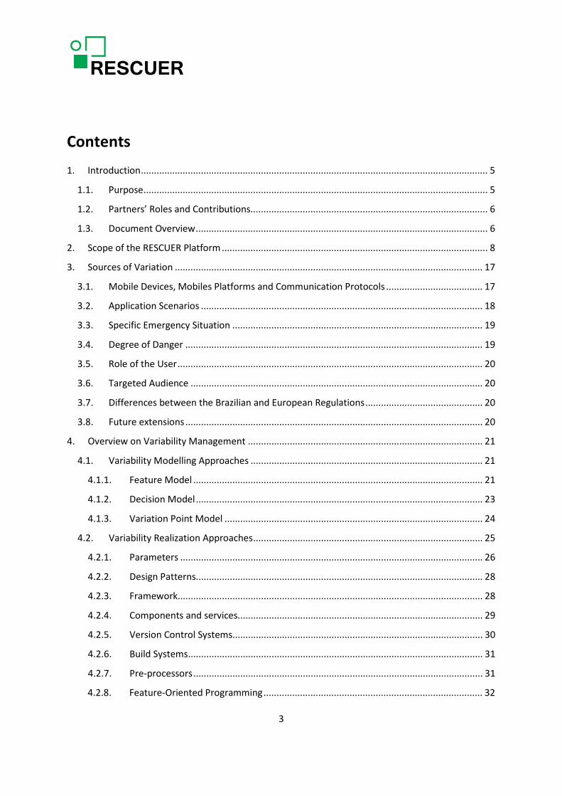
The RESCUER project aims at developing a smart and interoperable computer-based solution for supporting emergency and crisis management, with a special focus on incidents in industrial areas and on large-scale events. Both the concept and the objectives of the RESCUER project are described in the DoW [1], which is part of the EC Grant Agreement (Annex I). Figure 1 shows the main components of the RESCUER platform: 1) the Mobile Crowdsourcing Solution supports eyewitnesses and first responders in providing the command centre with information about an emergency situation, taking into account the different mobile devices that might be used and how people interact with those devices under stress; 2) the Data Analysis Solutions include approaches for integrating data from different operational forces as well as for combining, filtering, and analysing crowdsourcing information mashed up with open data; 3) the Emergency Response Toolkit provides the command centre with the most relevant information obtained from the crowd in appropriate format and time to support decision-making in the different phases of an emergency; and 4) the Communication Infrastructure insures the information flow between the crowd and the command centre even when the traditional communication infrastructure is overloaded.
Figure 1: Concept of the RESCUER Platform
5

The purpose of this document (D1.4.1: Portability & Variation Management Strategy 1) is to analyse the RESCUER platform from the perspective of a variant-rich system. A variant-rich system is a family of similar systems that can assume the shape of a product that can be configured for different customers and/or execution platforms, a software platform that is used to implement similar systems, or a software product line infrastructure from which a family of products can be instantiated. In other words, this deliverable has the purpose of analysing the sources of variation within the RESCUER platform scope and how they may affect the set of features to be provided by the platform in the first project iteration. This deliverable is especially concerned with offering guidelines for dealing with variation during the project life cycle and finding out the best way of combining variation management techniques and mobile applications development approaches, so that project partners can use those guidelines to develop the components of the RESCUER platform.
1.2. Partners’ Roles and Contributions
The partners involved in this task are Fraunhofer, UFBA, and MTM. Fraunhofer contributed to this deliverable by specifying the scope of the RESCUER platform, analysing the sources of variation applicable to the first project iteration, providing the overview on mobile applications development approaches, and creating the variability model of the RESCUER platform for the first project iteration. UFBA contributed to this deliverable with the overview on the variation management techniques, which included variability modelling techniques, variability realization techniques, as well as specific approaches for realizing variability in requirements. MTM revised the document. The recommendations provided as part of the first concept of the portability and variation management strategy have been compiled by the aforementioned partners according to their respective area of contribution to this deliverable.
1.3. Document Overview
The remainder of this document is structured as follows.
• Chapter 2 describes the scope of the RESCUER platform for the first project iteration. Ideally this chapter should be read before D1.1.1: Requirements Specification 1.
• Chapter 3 contains the sources of variation within the scope of the RESCUER platform and what variations they have triggered so far.
• Chapter 4 provides the overview on variation management, which presents the main techniques for variability modelling and variability realization, in addition to specific approaches for guiding project partners during requirements and architecture specifications.
• Chapter 5 presents the overview on mobile applications development, which covers mobile devices, mobile platforms, development approaches, and specific guidelines.
6

• Chapter 6 contains the first concept of a portability and variation management strategy for the RESCUER project, which comprises the variability model for the first project iteration and several recommendations regarding variation management techniques and mobile applications development.
• Chapter 7 presents the conclusion of this document. • Appendix A contains the list of potential features for the second and third project
iteration that were identified during the RESCUER platform scoping process.
7

2. Scope of the RESCUER Platform Software Product Line Scoping [2] is the process of identifying and describing areas of
functionality and capabilities of the product line where investment in reuse is economically useful and beneficial to product development. There are several approaches for Software Product Line Scoping [3,4], but those can be generalized into three main activities:
1. Product portfolio scoping: it determines (1) the products that the product line organization should be developing, producing, marketing, and selling; (2) the common and variable features that the products should provide in order to reach the long and short term business objectives of the product line organization, and (3) a schedule for introducing products to markets [4].
2. Domain scoping: it identifies and bounds the functional areas that are important to the envisioned product line and provide sufficient reuse potential to justify the product line creation [3,4].
3. Asset scoping: it determines specific assets to be developed for reuse. All these assets are part of the reuse infrastructure [3].
Therefore the main questions to be answered during the Software Product Line Scoping are: • Which products should be included in the product line? What is their market? When will
they be released? • Which features (distinguishing characteristics) will my product line have? Which product
will have what kind of features? Which are easy, which are risky features? • Which major domains (functional areas) are necessary for engineering the products?
What are „good“ or „bad“ domains for the product line (in terms of knowledge, stability, etc.)?
• Which assets should I have in my product line? Which components, documentation etc. already exist in a reusable form, which ones should be (re-)implemented?
Despite of being a sub-process of the Software Product Line Engineering process, the scoping ideas and activities are useful for defining any variant-rich system, in other words: any portfolio of similar software systems, regardless of the specific approaches for supporting variability management.
Thus, we performed a simplified version of the scoping process proposed by [2] to scope the RESCUER platform. The twofold goal of doing so was: 1) to clearly define the products/features to be supported/provided by the platform, 2) to progress towards the identification of the variabilities to be supported by the platform. Of course, the features identified during scoping are not detailed features but the ones that are relevant for distinguishing between the different products. We performed several scoping sessions that took place at different events in order to be able to involve representatives of chemical parks and of organizations in charge of dealing in public emergency situations in Brazil and in Europe (from now on called public security & safety organizations). In total we had four representatives of the chemical park in Brazil, four representatives of public security &
8

safety organizations in Brazil, five representatives of the chemical park in Austria, and four representatives of the public security & safety organizations in Austria. The scoping process was conducted by a scoping expert. The results of the scoping sessions are provided in Tables 1, 2, and 38.
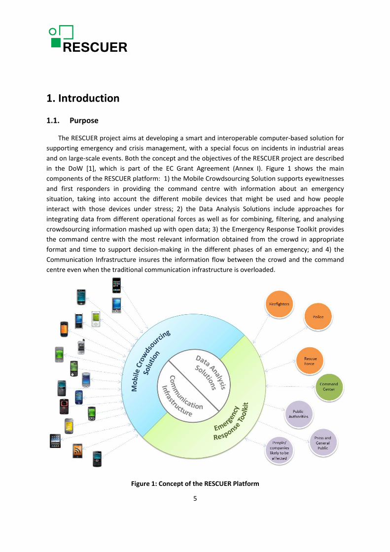
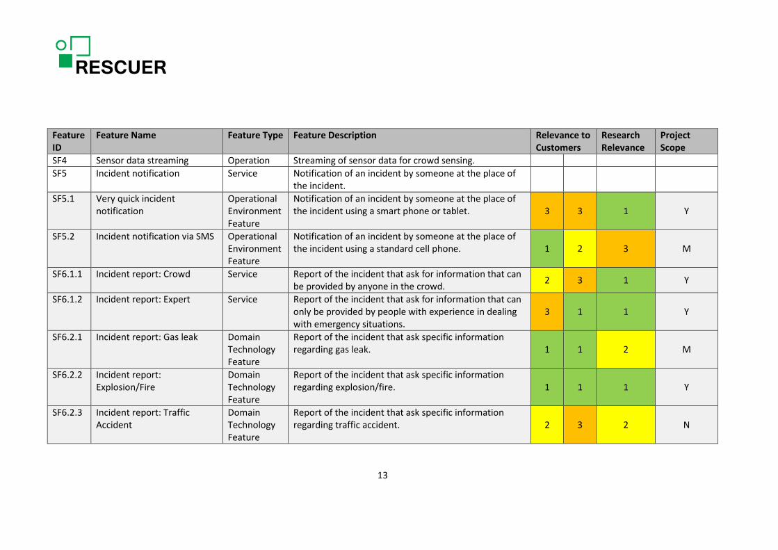
Table 1 lists the main product variants and their characteristics. As mentioned in the table, it is still not clear how the differences in the Brazilian and European regulations affect the RESCUER platform. We might define new product variants or address the differences in regulations in terms of customization of the two main product variants. Table 2 and Table 38 provide the list of features identified during scoping with the indication of their relevance to the customers (people responsible for ensuring security and safety in large-scale events or industrial areas) or to researchers. Table 2 only contains the features that are relevant for the first project iteration and Table 38 contains the features to be considered in the further project iterations. As this deliverable refers to the first project iteration, Table 38 is provided in Appendix A with the only purpose of documenting information that was collected to provide a generic overview on the RESCUER platform, but might change afterwards when they will be analysed in detail. The column “Feature Type” refers to the feature classification provided in [5]. The feature types are:
• Capabilities features, which are characterized as distinct services, operations, or non-functional aspects of products in a domain. Services are end-user visible functionality of products offered to their users in order to satisfy their requirements. Operations are internal functions of products that are needed to provide services. Non-functional features include end-user visible application characteristics that cannot be identified in terms of services or operations, such as presentation, capacity, quality attribute, usage, cost, etc.
• Operating environment features result from the fact that applications may run in different operating environments, e.g. different hardware or operating systems, or interface with different types of devices or external systems. Protocols used to communicate with external systems are also classified as environment features.
• Domain technology features are domain specific technologies that domain analysts or architects use to model specific problems in a domain or to “implement" service or operation features. Domain-specific theories and methods, analysis patterns, and standards and recommendations are examples. Note that these features are specific to a given domain and may not be useful in other domains.
• Implementation technique features are more generic than domain technology features and may be used in different domains. They contain key design or implementation decisions that may be used to implement other features (i.e., capability and domain technology features). Communication methods, design patterns, architectural styles, ADTs, and synchronization methods are examples of implementation techniques.
We consider this classification to be really helpful to support the activity of feature identification, despite of the fact that the scoping process does not have the goal of identifying all features, but only the most important ones to distinguish between product variants and to distinguish the product
9

variants from the competitors’ products. This is reflected in Table 2 and Table 38 by the fact that most features are of the service type, which are the most visible type of feature for the customers.
The features in light grey in Table 2 and Table 38 were part of a questionnaire that was applied with the representatives of chemical parks and of organizations in charge of dealing with public emergency situations. They were requested to inform the relevance of those features in terms of: “Must have”, “Good to have”, and “Not so relevant”. The answer were consolidated and again classified in three groups: High relevance (green, 1), medium relevance (yellow, 2), and low relevance (orange, 3). The results are presented in column “Relevance to Customers”, where the left-sided sub- column contains the results obtained in Europe and right-sided sub-column contains the results obtained in Brazil. In addition, all project site leaders (Europe and Brazil) were requested to provide the relevance of those same features from the research perspective, by using the scale “Main research goal / Highly Interesting”, “Nice research line / Necessary underlying feature”, and “Trivial / Standard software development”. The answers were consolidated and classified in three groups, using the same scale proposed for “Relevance to Customers”. The results are provided in column “Research Relevance”. The column “Project Scope” is a consolidation of “Relevance to Customers” and “Research Relevance“, and the used scale is: (Y)es, it is part of the project scope; (M)aybe, it might be covered; and (N)o, it will probably not be covered.
10

Table 1: Potential products from the RESCUER platform
Product ID
Product Name Product Description Market Segment Customizations Environmental Constraints
P1 RESCUER Industry Focus on gas leak and fire/explosion
Industrial parks in Europe and Brazil.
As differences in regulations have not been deeply investigated yet, it is still not clear whether there is need for customizations to the Brazilian market and to the European market.
Operational forces can only use explosion-safe equipment.
P2 RESCUER Large-Scale Event
Focus on disturbance in the crowd and fire/explosion
Organizations involved in ensuring security and safety in large-scale events.
As differences in regulations have not been deeply investigated yet, it is still not clear whether there is need for customizations to the Brazilian market and to the European market. For this product, there is a need for allowing independent download of the Mobile Crowdsourcing Solution and probably also for having it as a (suit of) add-on(s) to be integrated in the large-scale-event mobile application.
Operational forces can only use explosion-safe equipment.
11

Table 2: List of potential features with respective relevance to the Rescuer platform
Feature ID
Feature Name Feature Type Feature Description Relevance to Customers
Research Relevance
Project Scope
SF1 Monitoring of crowd behaviour
Service Monitoring of a specific area during a specific period of time in order to detect too high density, turbulence, and pressure.
2 1 1 Y
SF2.1 Sensor data gathering: position
Operation Gathering of position (direct sensing) using one of the available mechanisms: e.g. Wifi signal or GPS.
SF2.2 Sensor data gathering: movement speed
Operation Gathering of movement speed through direct sensing of GPS raw data.
SF2.3 Sensor data gathering: movement direction
Operation Gathering of movement direction through direct sensing of GPS raw data.
SF2.4 Sensor data gathering: altitude
Operation Gathering of altitude data from a specific sensor or using GPS coordinates (direct sensing). It is not relevant to F1, but it is relevant for supporting multimedia data analysis.
SF2.5 Sensor data gathering: device orientation
Operation Derivation of device orientation (indirect sensing). It is not relevant to F1, but it is relevant for supporting multimedia data analysis. It is a meta data to be attached to e.g. snapshots.
SF2.6 Sensor data gathering: movement track
Operation Derivation of movement track (indirect sensing) from the different positions of a mobile device throughout time.
SF3 Sensor data annotation Operation Annotation of content explicitly generated by the user (multimedia data, incident notifications or reports) with sensor data
12
Feature ID
Feature Name Feature Type Feature Description Relevance to Customers
Research Relevance
Project Scope
SF4 Sensor data streaming Operation Streaming of sensor data for crowd sensing. SF5 Incident notification Service Notification of an incident by someone at the place of
the incident.
SF5.1 Very quick incident notification
Operational Environment Feature
Notification of an incident by someone at the place of the incident using a smart phone or tablet. 3 3 1 Y
SF5.2 Incident notification via SMS Operational Environment Feature
Notification of an incident by someone at the place of the incident using a standard cell phone. 1 2 3 M
SF6.1.1 Incident report: Crowd Service Report of the incident that ask for information that can be provided by anyone in the crowd. 2 3 1 Y
SF6.1.2 Incident report: Expert Service Report of the incident that ask for information that can only be provided by people with experience in dealing with emergency situations.
3 1 1 Y
SF6.2.1 Incident report: Gas leak Domain Technology Feature
Report of the incident that ask specific information regarding gas leak. 1 1 2 M
SF6.2.2 Incident report: Explosion/Fire
Domain Technology Feature
Report of the incident that ask specific information regarding explosion/fire. 1 1 1 Y
SF6.2.3 Incident report: Traffic Accident
Domain Technology Feature
Report of the incident that ask specific information regarding traffic accident. 2 3 2 N
13
Feature ID
Feature Name Feature Type Feature Description Relevance to Customers
Research Relevance
Project Scope
SF6.2.4 Incident report: Blackout Domain Technology Feature
Report of the incident that ask specific information regarding blackout. 2 2 2 N
SF6.2.5 Incident report: Chemical spill
Domain Technology Feature
Report of the incident that ask specific information regarding chemical spills. 1 1 2 M
SF7 Multimedia attachment Operation Attachment of an image or video to an incident notification or report.
SF8 Integration with existing large-scale events apps (Alias: Integration2UpperLevelApp)
Non-functional
Integration of the Mobile Crowdsourcing Solution into the mobile applications of the large-scale event organization in order to maximize the possibility of people in the crowd having the Mobile Crowdsourcing Solution ready for instant use in their smart mobile devices.
SF9 Integration with existing procedures of the operational forces
Non-functional
Integration of the Mobile Crowdsourcing Solution into an everyday procedure of the operational forces to promote its smoothly use in emergency situations. It should also be investigated the possibility of people partially using it in their everyday life.
2 2 2 M
SF10 Crowd density analysis Service Analysis of position sensor data or videos to allow the detection of places with potentially dangerous crowd density.
14

Feature ID
Feature Name Feature Type Feature Description Relevance to Customers
Research Relevance
Project Scope
SF11 Crowd turbulence analysis Service Analysis of position sensor data to allow the detection of places with crowd turbulence, which means the detection of a part of the crowd moving against another part of the crowd.
SF12 Crowd pressure analysis Service Analysis of position sensor data or videos to allow the detection of places with crowd pressure, which means the detection of a crowd of certain size going to places that are suddenly narrower than the place of origin.
SF13.1 Crisis mapping: Incident location
Service Information layer that displays the location of the emergency situation or the several incidents of an emergency situation in a map of the area.
1 1 1 Y
SF13.2 Crisis mapping: Places of concern
Service Information layer that displays the places of concern in the surrounding area, such as factories with hazard material, schools or hospitals.
1 2 2 M
SF13.3 Crisis mapping: Safety & security areas
Service Information layer that displays the safety & security areas, which are pre-defined areas in the chemical parks or large-scale events where people should go in case of an incident.
2 2 2 M
SF13.4 Crisis mapping: Crowd behaviour
Service Information layer that displays the crowd density in the map of the area using e.g. heat map.
SF13.5 Crisis mapping: Crowdsourcing information
Service Information layer that displays selected data (after data analysis) coming from the crowd or operational forces with its reliability indicator having as a starting point for the user interaction the position of the data in the map of the area.
1 2 1 Y
15

Feature ID
Feature Name Feature Type Feature Description Relevance to Customers
Research Relevance
Project Scope
SF13.6 Crisis mapping: Free drawing Service Possibility of free drawing over the map of the area and any visualization layer over it. 2 2 3 N
SF14.1 User registration: Operational force
Service User registration for operational force. The user will at least inform the operational force he works for. Additional necessary information needs to be elicited.
SF14.2 User registration: Employee Service User registration for employee. The user will at least inform the company in the industrial area he works for. Additional necessary information needs to be elicited.
SF14.3 User registration: Volunteer Service User registration for volunteer. The user will at least inform the community around the industrial area in which he lives. Additional necessary information needs to be elicited.
SF14.4 User registration: Crowd Service User registration for anyone in the crowd. It will only ask 4 questions: “1) Do you authorize the collection of data for the solely purpose of supporting emergency handling in case an incident occurs?”, “2) Do you authorize the disclosure of the data received from you with the solely purpose of supporting emergency handling or crisis management?”, “3) Do you think you might help as a spontaneous volunteer in case of an incident?”, “4) Do you have experience in handling emergencies?”. It should be made clear for the user that the answers to question 1) and 2) are mandatory and no answer for 3) and 4) will be treated as “No” for each of the questions.
16
3. Sources of Variation The purpose of this chapter is to analyse the potential sources of variation of the RESCUER
platform that were presented in the DoW [1] in order to better understand how they affected the definition of the platform scope, but especially to understand how those sources of variation will affect the refinement of the product variants and features presented in the previous chapter. As mentioned in the DoW [1], variations in the RESCUER platform are expected due to:
1) The different mobile devices, mobile platforms and communication protocols, 2) The two application scenarios: incidents in large-scale events and incidents in industrial
areas, 3) The specific emergency situation, such as fire/explosion or chemical spill, 4) The degree of danger the person is exposed to, 5) The role of the person in the emergency situation, e.g. if the person is part of the crowd
or if it is a member of the operational forces, 6) The targeted audience of a communication, e.g. if the target audience is the company
where the incident took place, the industrial park or public authorities, 7) Possible differences between Brazilian and European regulations, 8) Future extensions, e.g. the addressing of a further type of emergency situation or the
inclusion of new role in the emergency situation.
3.1. Mobile Devices, Mobiles Platforms and Communication Protocols
Figure 2 represents the key features of a mobile device, which include the most popular operating systems or mobile platforms, and the most relevant communication protocols. It makes use of the feature diagram notation to illustrate standard features (represented as mandatory), alternative features (represented as alternative) and features that are not present in every mobile device (represented as optional). The features of special concern when developing a mobile application that should run in several different mobile devices are the screen size and resolution, and the operating system. Regarding the first, while the space occupied by some interface elements scaled down and up according to the screen size, other interface elements must be carefully planned according to the expected screen size. In regards to the second, the platform used to develop the mobile application strongly depends on the mobile operating system (native development) or on the fact that the mobile application is intended to run in several operating systems (cross-platform development). When choosing a development approach, the development of some features will be easier or more difficult than when choosing another development approach. The performance of the application later on may also be affected by this choice. As the Mobile Crowdsourcing Solution component of the RESCUER platform should run in several different mobile devices, Chapter 5 of this
17

deliverable investigates the advantages and disadvantages of the current mobile applications development approaches.
Figure 2: Key features of a mobile device
3.2. Application Scenarios
An incident in an industrial area is classified according its severity following the guidelines defined in [31]. The guidelines are specific for industrial areas. On the other hand, large-scale events are usually classified according to the security risk they represent. The Maurer scheme is one of the approaches for risk assessment of large-scale events [32]. As a consequence, the feature Classification of Severity (F2.2.1 in Table 31) only applies to the application scenario of incidents in industrial areas and the project consortia are going to investigate whether the security risk of a large-scale event is relevant information to be included in the Emergency Response Toolkit.
Furthermore, the feature User registration: Volunteer (SF14.3) was a feature proposed for the application scenario of incidents in industrial areas, more specifically by the Brazilian user organization of the consortium: COFIC. COFIC has a set of volunteers (normal citizens) who lives in the communities surrounding the open industrial area. Nowadays they have special radios in order to directly communicate problems to the industrial area or receive instructions. Using the RESCUER
18
platform, they would have smart phones. Nevertheless, this feature might be requested in industrial areas in Europe and/or in large-scale events depending on their size. Therefore, it should be possible to include this feature at the configuration time of a product variant.
No other variations have been identified so far in the features allocated to the first project iteration whose source of variation is the application scenario.
3.3. Specific Emergency Situation
The specific emergency situation influences the feature Very quick incident notification (SF5.1). Using this feature, the user of the Mobile Crowdsourcing Solution selects the type of incident he/she is witnessing. Furthermore, two features regarding incident report have been included in the scope of the first project iteration to address the particularities of the incident report for two specific emergency situations: SF6.2.1: Incident report: Gas leak and SF6.2.2: Incident report: Explosion/Fire. The variation represented by these two features is realized by adding questions specifically related to the type of incident to the standard questions of an incident report.
3.4. Degree of Danger
Deliverable D2.1.1 (Conceptual Model of Mobile User Interaction in Emergencies 1) states that the human cognitive capabilities available to interact with a mobile application are strongly reduced when people face an emergency situation. They concentrate on the main tasks at the moment, which are identifying and assessing the risks that the emergency situation brings and taking the necessary protective actions. Distance from the epicentre of the incident and timespan since the moment null of its occurence play a crucial role on the level of stress of the witness and consequently on their human cognitive capabilities. Therefore, deliverable D2.1.1 proposes a strategy for collecting crowdsourcing information at the place of the incident based on three steps, depending on the distance from the epicentre of the incident and timespan since the moment null, namely full-automatic information gathering, semi-automatic information gathering, and full interaction based information gathering. The feature Very quick incident notification (SF5.1) and the features regarding Incident report (SF6.1.x and SF6.2.x) correspond to the steps at the ends, full-automatic information gathering and full interaction based information gathering, respectively. Furthermore, we have added a feature Standard Notification (F1.1.2.2) to the feature model of the RESCUER platform (see Table 30) to cover the step in the middle. The user of the Mobile Crowdsourcing Solution starts with the Very quick incident notification (SF5.1, F1.1.2.1 in Table 30) and can go on with the Standard notification (F1.1.2.2 in Table 30) and the Incident report( SF6.1.x and SF6.2.x, F1.1.3 in Table 30) when s/he feels ready for them. The user interface will not make him/her aware of the three steps or features, but just inform that the contents have been sent to command centre and allow him/her to provide more information, if s/he can and wants to do it.
19

3.5. Role of the User
The role of the user in the emergency situation affects the way that they notify/report incidents. So far we have identified four roles (people belonging to operational forces, employees, volunteers, and people belonging to a crowd), as one can see in the features related to User Registration (SF14.1 to SF14.4). We are going to investigate in the next project iterations if there is need for refining the roles according to the different operational forces. As a result of the identification of the current four roles, two types of incident reports (SF6.1.1: Incident report: Crowd, SF6.1.2: Incident report: Expert) have been proposed: the one to be submitted by the crowd, which includes the registered volunteers and employees, and the one to be submitted by experts, who are represented by the operational forces and people who claimed to have experience in handling health emergencies. The feature Standard notification (F1.1.2.2 in Table 30) is structured in the same way. The difference between the two types of notification/report is the appropriateness of the questions to the level of knowledge and experience of the people with emergency situations.
3.6. Targeted Audience
The targeted audience of a communication is only relevant for the third project iteration.
3.7. Differences between the Brazilian and European Regulations
No features have been identified so far as a consequence of differences in the European and Brazilian regulations or de-facto standards related to emergency handling and crisis management or related to the use of crowdsourcing information to this end. The consortia have to further investigate this source of variation to find out whether it really represents a source of variation. So far, the only difference of the RESCUER platform for the different markets (Europe and Brazil) is the feature User registration: Volunteer (SF14.3), which, as mentioned in Section 3.2, is very important in the context of Brazilian industrial areas, but not especially relevant in the context of European industrial areas.
3.8. Future extensions
Two types of extensions are expected and, therefore, should be carefully planned in the portability and variation management strategy: 1) new types of incident, and maybe 2) new user roles in an emergency situation or the refinement of the already proposed ones.
20
4. Overview on Variability Management Similarly to the Software Product Line Scoping process (Chapter 2), the techniques used for
modelling and realizing variability in software product line engineering can be useful for modelling and realizing other types of variant-rich systems too. These techniques are used in the process of domain engineering [6], which is the process of developing the assets that are common to all product variants or that contain systematic variability, so that they can be reused when developing/deriving the specific product variants, which constitutes the process of application engineering.
4.1. Variability Modelling Approaches
Variability modelling is essential for defining and managing the commonalities and variabilities in software product lines. Nowadays, several variability modelling approaches exist to support domain and application engineering activities [10], each with a slightly different focus and goal. Next, we present the most representative ones.
4.1.1. Feature Model
Feature modelling is the activity of identifying externally visible characteristics of products in a domain and organizing them into a model called feature model [5]. Lee et al. [5] proposes the feature classification in terms of capabilities (services, operations, or non-functional properties), operating environments, domain technologies, and implementation techniques, as already presented in Chapter 2, to support the identification and modelling of features.
In a feature model, common features among different products are modelled as mandatory features, while different features among them may be optional or alternative. Optional features represent selectable features for products of a given domain and alternative features indicate that no more than one feature can be selected for a product. Features are not always freely combinable. Not all features maybe compatible, and some features may require the presence of other features (for example, and “B implies C”). Therefore, a feature model describes relationships between features and defines which feature selections are valid [7].
A feature diagram uses a graphical notation to specify a feature model in terms of an AND/OR hierarchy of features and constraints among them [5,7]. The feature model is represented by a tree whose nodes are labelled with feature names and the semantics is specified by a translation into propositional logic. Different notations convey various parent–child relationships between features and their constraints [5]. The composed-of relationship is used if there is a whole-part relationship between a feature and its sub-features. In cases where features are generalization of sub-features, they are organized using the generalization/specialization relationship. The implemented-by relationship is used when a feature (i.e., a feature of an implementation technique) is necessary to
21

implement the other feature. Figure 3 shows a simplified feature model of a Private Branch Exchange (PBX) system.
Figure 3: An example of feature model: PBX product line [5]
Table 3 summarizes the strengths and weaknesses of modelling variability with feature models.
Table 3: Strengths and weaknesses of feature models
Strengths Weaknesses o Supports the understanding of variability [5,7] o Simple [5,7] o Feature diagram is widely used in practice [5] o Dependencies can be clearly visualized in
feature diagrams [7] o Some textual representation (e.g. µTVL) [28]
can be formally verified o Availability of tools [7]
o Relationship to others artifacts (such as components, interfaces) is not usually addressed [5]
22

4.1.2. Decision Model
The Software Productivity Consortium Services Corporation [11] defines decision model as a set of decisions that are adequate to distinguish among the members of a product family and to guide the adaptation work products.
According to [10], most decision model approaches were either inspired by industrial applications or developed in close collaboration with industry. Several of them are discussed in a recent comparative analysis [12]. In VManage [13] and the approach by Weiss and Lai [14], a decision model is a document defining the decisions that must be made to specify a member of a domain [15]. The tool-supported DOPLER approach [16] has been developed to guide the derivation of customer-specific products. The work of Schmid and John [29] provides a common modelling foundation that can be mapped to a wide range of notations. Figure 4 depicts a partial decision model for the example of a mobile phone in a tabular representation, whereas Figure 5 shows a partial decision model of bottle sorting automation system.
Figure 4: Decision model in a tabular notation[29]
Figure 5: Decision model in a graphical representation [16]
23
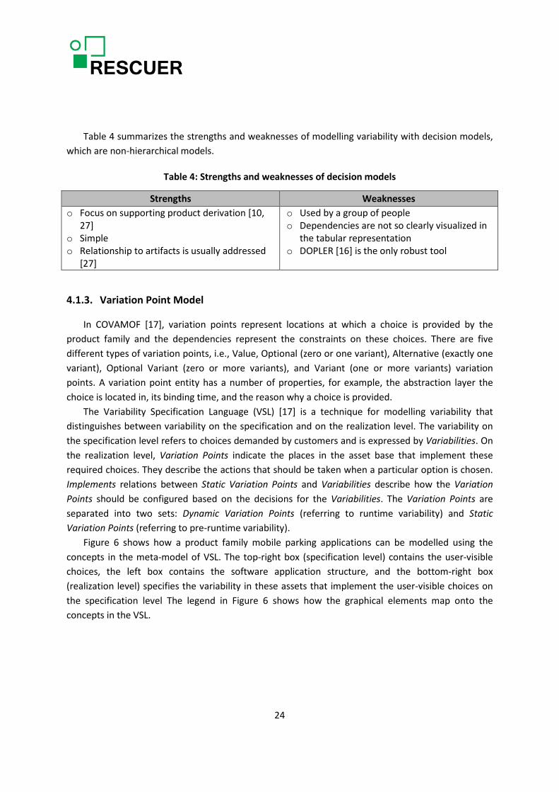
Table 4 summarizes the strengths and weaknesses of modelling variability with decision models, which are non-hierarchical models.
Table 4: Strengths and weaknesses of decision models
Strengths Weaknesses o Focus on supporting product derivation [10,
27] o Simple o Relationship to artifacts is usually addressed
[27]
o Used by a group of people o Dependencies are not so clearly visualized in
the tabular representation o DOPLER [16] is the only robust tool
4.1.3. Variation Point Model
In COVAMOF [17], variation points represent locations at which a choice is provided by the product family and the dependencies represent the constraints on these choices. There are five different types of variation points, i.e., Value, Optional (zero or one variant), Alternative (exactly one variant), Optional Variant (zero or more variants), and Variant (one or more variants) variation points. A variation point entity has a number of properties, for example, the abstraction layer the choice is located in, its binding time, and the reason why a choice is provided.
The Variability Specification Language (VSL) [17] is a technique for modelling variability that distinguishes between variability on the specification and on the realization level. The variability on the specification level refers to choices demanded by customers and is expressed by Variabilities. On the realization level, Variation Points indicate the places in the asset base that implement these required choices. They describe the actions that should be taken when a particular option is chosen. Implements relations between Static Variation Points and Variabilities describe how the Variation Points should be configured based on the decisions for the Variabilities. The Variation Points are separated into two sets: Dynamic Variation Points (referring to runtime variability) and Static Variation Points (referring to pre-runtime variability).
Figure 6 shows how a product family mobile parking applications can be modelled using the concepts in the meta-model of VSL. The top-right box (specification level) contains the user-visible choices, the left box contains the software application structure, and the bottom-right box (realization level) specifies the variability in these assets that implement the user-visible choices on the specification level The legend in Figure 6 shows how the graphical elements map onto the concepts in the VSL.
24

Figure 6: A parking product family modelled in VSL [17]
Table 5 summarizes the strengths and weaknesses of modelling variability with variation point models, which are non-hierarchical models.
Table 5: Strengths and weaknesses of variation point models
Strengths Weaknesses o Focus on the link to / representation of
architecture o Provision of levels of abstraction o Dependencies can be formal or informal o More concepts/elements
o Dependencies are not so clearly represented in VSL
o Used by a group of people
4.2. Variability Realization Approaches
Apel et al. [7] introduced three dimensions for classifying variability implementation techniques: (i) Binding Time, (ii) Technology, and (iii) Representation. The former can be distinguished between compile-time binding, load-time binding, and run-time binding. Compile-time variability is decided before or at compile time, examples include implementing variable code with pre-processors and feature-oriented programming. Load-time variability is decided after compilation when the program is started, for example, through command-line parameters or configuration files. With Run-time variability, decisions can be made and changed during program execution, examples are simple
25

parameter-based variability and context oriented programming. Some implementation mechanisms support multiple binding times.
Regarding Technology, it is possible distinguish the variability implementation techniques that are based on mechanisms provided by a programming language, called language-based approaches, from those that are based on tools that operate on software artifacts to derive products, called tool-based approaches. A language-based approach uses the mechanisms provided by a host programming language to implement features and to derive products. Example of a classic language-based approach is to realize variability with run-time parameters. A tool-based approach uses one or more external tools to implement or represent features in code and to control the product-derivation process. Example of a classic tool-based approach is to use a pre-processor that transforms software artifacts based on a given feature selection.
In terms of Representation, there are annotation-based and composition-based approaches, which differ in the way they represent variability in the code base and the way they generate products. Annotation-based approaches annotate a common code base, such that code that belongs to a certain feature is marked accordingly. During product derivation, all code that belongs to deselected features or invalid feature combinations is removed (at compile time) or ignored (at run time) to form the final product. A standard example is implementing variable code using the C pre-processor. Composition-based approaches implement features in the form of composable units, ideally one unit per feature. During product derivation, all units of all selected features and valid feature combinations are composed to form the final product. A classic example is a framework that can be extended with plug-ins.
Table 6 classifies different variability implementation techniques according to the dimensions aforementioned. Some approaches have multiple instances with different properties, such that the classifications are not disjoint. For example, some component systems support both static composition and dynamic composition; others are both language-based and tool-based. Each technique has advantages and disadvantages, as it will be explained in the following subsections [7].
4.2.1. Parameters
A simple way to implement variability is to use conditional statements (such as “if” and “switch”) to alter the control flow of a program at run-time. Conditional statements are typically controlled by configuration parameters passed to a method or a module, or set as global variables in a system. Different parameter assignments lead to different program executions. Table 7 summarizes the strengths and weaknesses of implementing variability with parameters [7].
26

Table 6: Classification of variability implementation techniques [5]
Table 7: Strengths and weaknesses of implementing variability with parameters [7]
Strengths Weaknesses o Easy to use, well-known o Flexible and fine grained o First-class programming-language support o Different configurations within the same
program possible
o All code is deployed, no compile-time configuration
o Often used in ad-hoc or undisciplined fashion o Boilerplate code to propagate method
arguments or non-modular solutions o Scattering and tangling of configuration
knowledge o Separation of feature code and information
hiding possible, but left to the discipline of developers
o Extensions typically require invasive changes, but little preplanning though
o No support for non-code artifacts o Nontrivial tracing between features and code,
and thus difficult to analyse statically
27

Boilerplate code is the sections of code that have to be included in many places with little or no alteration. Feature code means the code that implements a feature. It might be scattered across multiple files and modules, which makes tracing a feature to all code fragments implementing it a nontrivial task. Furthermore, feature code might be tangled with the base code and code of other features. Due to its crosscutting nature, it is difficult to encapsulate a feature’s code behind an interface and to place all feature code in one cohesive structure.
4.2.2. Design Patterns
A problem of the parameter approach is that variability is scattered and hard-wired in the source code, often in an undisciplined fashion. Consequently, many patterns have evolved on how variability can be separated and decoupled, among them many well-known design patterns for object-oriented programming, such as observer, template method, strategy, decorator. The strengths and weaknesses of design patterns are presented in Table 8 [7].
Table 8: Strengths and weaknesses of implementing variability with design patterns [7]
Strengths Weaknesses o Well established, ease communication
between developers o Guidelines for disciplined design o First-class programming-language support o Different configurations within the same
program possible o Separate feature code from base code,
possibly with clear interfaces o Non-invasive extensions without modifying
the base code, given a preplanning effort
o Boilerplate code and architectural overhead o Preplanning of extension points necessary
4.2.3. Framework
A framework is an incomplete set of collaborating classes that can be extended and tailored for a specific use case. It represents a reusable base implementation for a related set of problems, and thus perfectly fits the needs of product line development. Frameworks, especially, black-box frameworks, are a suitable way to implement variability in product lines. Using typical plug-in loaders, individual products are created by composing plug-ins at load-time, but in principle run-time changes are possible [7].
Like the parameter approach, frameworks are language-based. However, frameworks differ from parameters in that they are primarily composition-based, not annotation-based, and in that variability is usually decided at load-time, not run-time. Table 9 summarizes the strengths and weaknesses of implementing variability with frameworks [7].
28
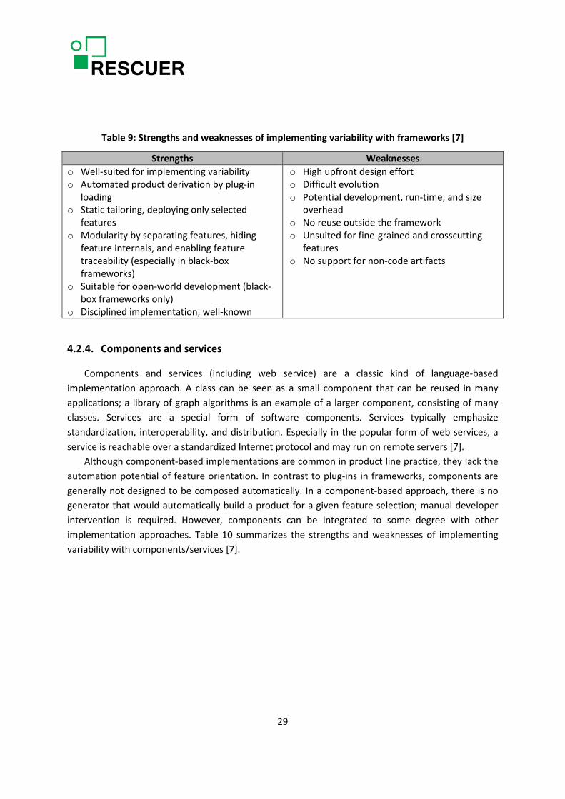
Table 9: Strengths and weaknesses of implementing variability with frameworks [7]
Strengths Weaknesses o Well-suited for implementing variability o Automated product derivation by plug-in
loading o Static tailoring, deploying only selected
features o Modularity by separating features, hiding
feature internals, and enabling feature traceability (especially in black-box frameworks)
o Suitable for open-world development (black-box frameworks only)
o Disciplined implementation, well-known
o High upfront design effort o Difficult evolution o Potential development, run-time, and size
overhead o No reuse outside the framework o Unsuited for fine-grained and crosscutting
features o No support for non-code artifacts
4.2.4. Components and services
Components and services (including web service) are a classic kind of language-based implementation approach. A class can be seen as a small component that can be reused in many applications; a library of graph algorithms is an example of a larger component, consisting of many classes. Services are a special form of software components. Services typically emphasize standardization, interoperability, and distribution. Especially in the popular form of web services, a service is reachable over a standardized Internet protocol and may run on remote servers [7].
Although component-based implementations are common in product line practice, they lack the automation potential of feature orientation. In contrast to plug-ins in frameworks, components are generally not designed to be composed automatically. In a component-based approach, there is no generator that would automatically build a product for a given feature selection; manual developer intervention is required. However, components can be integrated to some degree with other implementation approaches. Table 10 summarizes the strengths and weaknesses of implementing variability with components/services [7].
29

Table 10: Strengths and weaknesses of implementing variability with components/services [7]
Strengths Weaknesses o Well-known and established implementation
technique o Static tailoring, deploying selected features
only o Separation of concerns, information hiding,
and feature traceability o Reuse within and beyond the product line o Reuse of third-party implementations o Reuse in distributed environments, even with
features maintained and run by third parties (especially services)
o Uniformly applicable to many languages
o No automated product derivation, glue code is necessary
o Difficult evolution o Potential development, run-time, and size
overhead o Preplanning necessary to size components o Unsuited for fine-grained and crosscutting
features
4.2.5. Version Control Systems
Version control systems are best known for tracking revisions of source code, that is, variation over time. Each revision gets an identifier and possibly a comment explaining the changes. Developers can go back in time to retrieve earlier revisions of the source code and investigate changes. Revisions are ordered, newer revisions supersede previous ones.
Since developers use version control systems routinely, it seems tempting to use the well-known branching and merging techniques and mature tools for feature variability. In contrast to language-based variability, branching can be used uniformly for code and non-code artifacts, and changes can be applied at arbitrary granularity (from removing directories to changing individual characters). Table 11 summarizes the strengths and weaknesses of implementing variability with version control systems [7].
Table 11: Strengths and weaknesses of implementing variability with version control systems [7]
Strengths Weaknesses o Well-known, established, and mature tools o External infrastructure o Arbitrary compile-time customization
independent of granularity and crosscutting o Uniform application to source code and non-
code artifacts o Only minor effort for preplanning
o Mixture of revisions and variants o Encourages development of variants, not
features. No feature traceability, no separation of feature code, and no information hiding
o No structured reuse (copy and edit of plain text)
o Relies on merging, prone to conflicts and errors
o Hard to maintain with many branches. Almost all practical tools are text based
30

4.2.6. Build Systems
A build system is responsible for scheduling and executing all build-related tasks, which may include running generators, compiling source code, running tests, and creating and copying deliverable units. With a build system, developers document and automate the build process. Especially in large projects, a build process is not trivial, since many different build tools (compilers, linkers, parser generators, testing frameworks, documentation generators) and dependencies (libraries, tools) are involved. As a build system can control which files are compiled and how, it is natural to use it for variability at compile time. Typically, build systems use a parameter-based approach when they are executed at compile time. Table 12 summarizes the strengths and weaknesses of implementing variability with build systems [7].
Table 12: Strengths and weaknesses of implementing variability with build systems [7]
Strengths Weaknesses o Well-known and established tools o Suitable for conditional compilation at file
level o Orchestration of other variability mechanisms o Arbitrary compile-time customization o Uniform application to source code and non-
code artifacts o No extensive preplanning necessary
o Limitation to file-level variability and discouragement of systematic preplanning leads to code replication
o Largely unsuitable for feature-oriented programming at a fine grain
o No notion of modularity o Feature traceability at the file level only o Undisciplined and complex scripts can
become hard to maintain and analyse
4.2.7. Pre-processors
A pre-processor is a tool that manipulates source code before compilation. A popular pre-processor is the C pre-processor cpp, which is used in almost every C and C++ project. It provides directives to inline files, to define macros, and to remove code fragments based on user-defined conditions. In addition to cpp, many other pre-processors exist and are used for specific purposes. Most important for variation management, pre-processors typically provide facilities for conditional compilation, where marked code fragments in the source code are conditionally removed before compilation— #ifdef and #endif in cpp. Conditional compilation is probably the most common mechanism for implementing variability in industrial practice [7].
Pre-processors are controversial (Table 13). On the one hand, they are widely used in practice. On the other, numerous studies discuss the negative effect of pre-processor usage on code quality and maintainability [7].
31

Table 13: Strengths and weaknesses of implementing variability with pre-processors [7]
Strengths Weaknesses o Easy to use, well-known o Simple programming model: annotate and
conditionally remove o Compile-time customization of the source
code. No boilerplate code o Flexible and supports arbitrary granularity o Little preplanning required o Features usually traceable to (several) code
locations o Lightweight mechanism for extractive product
line adoption o Uniform application to source code and non-
code artifacts
o Scattering and tangling of feature code and configuration knowledge. No clear separation of concerns
o No support for information hiding o May obfuscate source code o Often used in ad hoc or undisciplined fashion o Prone to simple errors o Difficult to analyse and to write tool support
for the underlying language
4.2.8. Feature-Oriented Programming
Feature-oriented programming (FOP) is a composition-based approach for building software product lines that relies directly on the notion of features. The idea is to decompose a system’s design and code into the features it provides. This way, the structure of a system aligns with its features, ideally, one module or component per feature. To this end, new language constructs are needed to express which parts of a program contribute to which features and to encapsulate the feature’s code in composable, modular units. Table 14 summarizes the strengths and weaknesses of implementing variability with FOP [7].
Table 14: Strengths and weaknesses of implementing variability with FOP [7]
Strengths Weaknesses o Easy to use language-based mechanism,
requires only minimal language extensions o Compile-time customization of source code
without run-time overhead o Separation of (possibly crosscutting) feature
code into distinct feature modules o Direct feature traceability from a feature to
its implementation in a feature module o Conceptually uniformly applicable to code
and non-code artifacts, tools already cover many languages
o Little preplanning required due to mixing-based extension mechanism
o Requires adoption of a language extension or unfamiliar composition tools as part of the development process
o Granularity at the level of methods (or other named structural entities)
o Composition is syntax-directed and does not offer enforced interfaces between feature modules
o Tools need to be constructed for every language, but these may be generated
o Only academic tools so far, little experience in practice
32

4.2.9. Aspect-Oriented Programming
Aspect-oriented programming (AOP) aims at the modularization of crosscutting concerns. During the discussion of FOP in [12], they have already considered a kind of crosscutting concern: A collaboration extends a program at different places, thus it cuts across the module boundaries introduced by classes. While FOP has been developed as a feature implementation (collaboration implementation) technique, AOP targets crosscutting concerns from a different perspective: AOP aims at reducing code scattering, tangling, and replication induced by crosscutting concerns that are not well-separated [7].
AOP is a language-based and composition-based approach for product-line implementation, where selected aspects and classes are woven to form the desired product. Different weaving technologies support different binding times including compile-time binding (such in AspectJ) and load-time binding. Table 15 summarizes the strengths and weaknesses of implementing variability with AOP [7].
Table 15: Strengths and weaknesses of implementing variability with AOP [7]
Strengths Weaknesses o Compile-time variability without run-time
overhead; load-time variability possible as well
o Separation of (possibly crosscutting) feature code into distinct aspects
o Direct feature traceability from feature to its implementation in an aspect
o Fine granularity based on events during the program execution, depending on the join point model
o Little or no preplanning effort required
o Requires adoption of a sophisticated language extension, including a novel programming paradigm
o Different aspect-oriented extensions for different code and non-code languages, only experimental uniform models so far
o Composition is syntax-directed and does not offer enforced interfaces between feature modules
o Though conceptually uniform, tools need to be constructed for every language
o Only academic tools so far, little application in practice
4.2.10. Virtual separation of concerns
Virtual separation of concerns (VSC) is a tool-based approach for product line development. Based on a combination of tracing information, visualization facilities, source-code views, and the integration of feature models, code that belongs to individual features can be displayed, edited, and understood in separation. For example, one can view the code only of a certain feature or feature combination, whereas the remaining code is hidden. Additionally, a developer can get a view on the combined code of multiple features (thus seeing the interacting code fragments in place), which is not easily possible in language-based approaches [7].
33
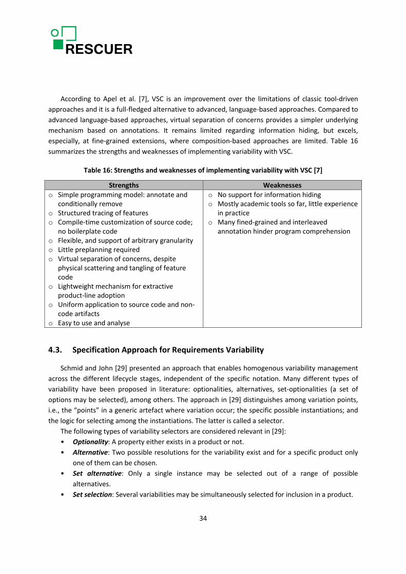
According to Apel et al. [7], VSC is an improvement over the limitations of classic tool-driven approaches and it is a full-fledged alternative to advanced, language-based approaches. Compared to advanced language-based approaches, virtual separation of concerns provides a simpler underlying mechanism based on annotations. It remains limited regarding information hiding, but excels, especially, at fine-grained extensions, where composition-based approaches are limited. Table 16 summarizes the strengths and weaknesses of implementing variability with VSC.
Table 16: Strengths and weaknesses of implementing variability with VSC [7]
Strengths Weaknesses o Simple programming model: annotate and
conditionally remove o Structured tracing of features o Compile-time customization of source code;
no boilerplate code o Flexible, and support of arbitrary granularity o Little preplanning required o Virtual separation of concerns, despite
physical scattering and tangling of feature code
o Lightweight mechanism for extractive product-line adoption
o Uniform application to source code and non-code artifacts
o Easy to use and analyse
o No support for information hiding o Mostly academic tools so far, little experience
in practice o Many fined-grained and interleaved
annotation hinder program comprehension
4.3. Specification Approach for Requirements Variability
Schmid and John [29] presented an approach that enables homogenous variability management across the different lifecycle stages, independent of the specific notation. Many different types of variability have been proposed in literature: optionalities, alternatives, set-optionalities (a set of options may be selected), among others. The approach in [29] distinguishes among variation points, i.e., the “points” in a generic artefact where variation occur; the specific possible instantiations; and the logic for selecting among the instantiations. The latter is called a selector.
The following types of variability selectors are considered relevant in [29]: • Optionality: A property either exists in a product or not. • Alternative: Two possible resolutions for the variability exist and for a specific product only
one of them can be chosen. • Set alternative: Only a single instance may be selected out of a range of possible
alternatives. • Set selection: Several variabilities may be simultaneously selected for inclusion in a product.
34
• Value reference: The value of the decision variable can be directly included in the product line model. This, of course, only makes sense with decision variables that only assume a single value in application engineering.
The concepts discussed so far are representation independent. In order to represent variation points in diverse software engineering artifacts (domain model, code, etc.), which employ a specific representation technique, it is necessary to map the different types of variability selectors to the target notation [29]. In order to derive a context-specific representation of variability mechanisms, their approach perform the following steps:
1. Determine the required level of granularity Prior to determining a specific approach to variability representation, it is necessary to identify
the kind of structures in the target notation, which we need to make variable. This particularly implies to identify the granularity of constructs that can be variable. Depending on the underlying notation, this can take on several forms. For example, for business process representations, this may include individual process steps, complete action sequences, or even business processes.
2. Identify approach for representing variability selectors In order to represent variability based on existing representation formalism, we must extend it in
a homogenous way, so that the variability representation is well integrated. This requires a basic approach that is well compatible with the underlying notation. In particular, for formally defined representation formalisms, this requires an extension of their underlying meta-model.
The most simple extension is possible in the context of text-based representations, as their underlying meta-model allows any kind of description. In this context the authors propose the use of special delimiters of which one can be reasonable sure that they will not occur in the remainder of the text. In their example, the delimiters “are <<” and “>>”. All the text that is enclosed in these “brackets” is then part of a selector. The specific type of the selector is then given by a keyword.
3. Determine supported selector types In spite of the fact that there are different types of selector, in the context of a specific modelling
situation, only a subset of these types is usually necessary. • Optionality: In case the underlying notation requires that all steps are required in some way,
it is inappropriate to use an optionality as the removal of a step may decompose the overall flow in several unconnected sub-flows.
• Alternative: For some system types, possibilities are hardly ever exclusive, but they can be combined.
• Set alternative: This can be even rarer than the previous case. It is strongly context dependent whether this selector type is particularly useful.
• Set selection: For certain notations (e.g., programming languages), the set alternative must be instantiated by additionally providing some gluing mechanism for runtime. In this case this selector must either be forbidden or treated in a special way.
35

• Value reference: It strongly depends on the level of abstraction of the notation how important this mechanism is.
4. Map selector types to target notation The next step is to identify a notation for each of the identified selectors. This is already mainly
determined by the decisions that have been made in the previous steps. For example, in the case of a text-based notation, one must determine a specific keyword for the different selectors and one must define the specific notation for selecting individual alternatives.
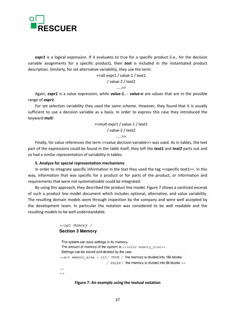
5. Analyse for special representation mechanisms Finally, there might be some special notational elements that do particularly apply in the context
of the target notation. An example can be the optional variant decision.
Schmid and John [29] presented a case study of their variability management approach, in which the approach was applied in practice with text-based requirements in an embedded systems company.
1. Determine the required level of granularity The extension of the existing representation had to take two representations into account,
unstructured text and tables. They did explicitly exclude graphical representations in this context.
2. Identify approach for representing variability selectors In order to be able to model and manage variability, the existing mechanisms for writing textual
requirements had to be extended into a product line modeling approach. They decided to use a decision model that was realized using an Excel-table. For the mapping of the selector types onto the textual specification they decided to use textual constructs framed with “<<” “>>”. To represent variability in tables they decided to integrate an extra column into each table and describe the relevancy of the row in the corresponding cell. It would also have been a possibility to use the same approach as for text, so to use constructs framed with “<<” “>>” every time a variation point occurs in a table.
3. Select supported selector types They decided not to support the set alternative, as it is a special case of the set selection. Thus,
they supported the following selector elements: optionality, alternative, set selection and value reference.
4. Map selector types to target notation As they decided to use textual constructs framed with “<<” “>>”, they introduced a keyword for
each of the selected selector types. They described optional variability in the following way:
<<opt expr1 / text >>
36
expr1 is a logical expression. If it evaluates to true for a specific product (i.e., for the decision variable assignments for a specific product), then text is included in the instantiated product description. Similarly, for set alternative variability, they use the term:
<<alt expr1 / value-1 / text1 / value-2 / text2
.....>> Again, expr1 is a value expression, while value-1…- value-n are values that are in the possible
range of expr1. For set selection variability they used the same scheme. However, they found that it is usually
sufficient to use a decision variable as a basis. In order to express this case they introduced the keyword mult:
<<mult expr1 / value-1 / text1 / value-2 / text2
.....>> Finally, for value references the term <<value decision-variable>> was used. As in tables, the text
part of the expressions could be found in the table itself, they left the text1 and text2 parts out and so had a similar representation of variability in tables.
5. Analyze for special representation mechanisms In order to integrate specific information in the text they used the tag <<specific text1>>. In this
way, information that was specific for a product or for parts of the product, or information and requirements that were not systematizable could be integrated.
By using this approach, they described the product line model. Figure 7 shows a sanitized excerpt of such a product line model document which includes optional, alternative, and value variability. The resulting domain models went through inspection by the company and were well accepted by the development team. In particular the notation was considered to be well readable and the resulting models to be well understandable.
Figure 7: An example using the textual notation
37

Another approach related to the requirements engineering process was proposed by[8], which is called RiPLE-RE. In this approach, the Domain Requirements Specification (DRS) is composed of Feature Model, Domain Requirements, and Domain Use Cases. These work products are specified with notations that represent SPL variabilities and enable the product instantiation. In other words, the DRS becomes a concrete product requirements specification when instantiated.
According to [8], when requirements are described, their variabilities also need to be represented. There are mandatory and variant requirements. A mandatory requirement is common for all products in the SPL. A variant requirement is not common for all products in the SPL. The variability can also be found in the requirement part, i.e. a text fragment can be a variant. The attributes for each requirement are defined in Table 17.
Table 17: Requirements attributes [8]
The requirement variability type can be defined from feature model whether requirement is mapped to feature and this feature represents directly the requirement or it encompasses the requirement. When a feature encompasses requirements, their variabilities types are the same. If the feature variability type is Optional, Alternative or OR, then the requirement variability type is Variant. When a requirement is not mapped to feature then its variability type must be identified in elicitation.
In a requirement, a Variation Point (VP) represents the variability found in the requirement text fragment. A requirement can have 0 to n VPs. Figure 8 presents an example of requirement variation points, whereas Table 18 presents the VP attributes.
38

id = FR1 type = Functional name = Door control variability type = Mandatory priority = High rationale = Assure security description: text = The system must monitor the state of doors, whether they are open, closed, locked, or unlocked. vp id = FR1.VP1 variant id = FR1.VP1.V1: Doors can be unlocked electronically based on the following identification mechanism: vp id = FR1.VP2 binding time = scoping-time implication = FR1.VP description = identification mechanism type cardinality min = 1 max = 3 variant id = FR1.VP2.V1: fingerprint scanner variant id = FR1.VP2.V2: keypad variant id = FR1.VP2.V3: magnetic card
Figure 8: Example of a functional requirement with implication among VPs [8]
When utilizing use cases for product line, they should be extended with variability mechanism. In this context, several elements may potentially be a variant, such as use case as whole, actors, dependency, rationale, precondition, post-condition, and event flows. Moreover, the use case variability type is defined from the requirements variability type. This definition should be based on the following rules:
1. If the use case corresponds to whole requirement, thus its variability type is the same of the requirement.
2. Otherwise, if the use case is a common part (non-variant) of a mandatory requirement, then it is mandatory.
3. Otherwise, if the use case is a variant part of any requirement, then it is variant. 4. Otherwise, if the use case is a common part of variant use cases only, then it is variant.
Use cases have the set of attributes defined in Table 19. A Variation Point (VP) in a use case represents variability found in the use case element. A use case can have 0 to n VPs and the attributes of the VPs are the same as defined for VP in requirements (Table 18). In order to describe domain use cases appropriately, the following guideline should be applied:
1. Identify the following elements for all products: actors, interaction between actors and system, preconditions and post-conditions, rationale.
2. Identify synonyms and homonyms elements. (e.g. actors with different names but the same role, such as client and customer). This information must be described in the glossary.
3. Identify common responsibilities among similar actors and become them in an abstract actor (e.g. configuration manager and webmaster actors become an abstract administrator actor).
39

4. Identify common and variable elements among products. The variabilities found should be represented according to the proposed VP notation.
Table 18: Variation point attributes [8]
40

Table 19 Use Cases attributes [8]
VPs in use case handle one of the two situations: small and complex variations. For small
variations, the VP is described in the use case itself, identifying the place in the use case where the change can occur. When a use case becomes too complex because it has too many variants and exceptional sequences of interactions, dependencies among use cases can be defined by using include and extend relationships.
According to [14], using include and extend relationships to handle variations in a product line works better when the use case contains a block of functionality that can be described as a sequence of interactions between an actor and the system. In some situations, however, a small variation affects only one or two lines in the use case descriptions. Trying to address those situations in separate use cases is liable to fragment the use case model, leading to several small use cases.
Figure 9 provides an example of domain use case description.
41

uc id = UC1 name = Front door unlock variability-type = Mandatory rationale = Controlling home access by authentication actors = inhabitant preconditions = inhabitant registered in the system main flow Inhabitant approaches the front door System requests authentication [UC1.VP1] [AF1] System permits entry to the home. [EF1] alternative flow id = AF1 Inhabitant cancels operation exception-flow id = EF1 System does not permit entry to the home Inhabitant is not registered An error message is shown to user post condition = the front door is unlocked and inhabitant can access the home vps vp id = UC1.VP1 description = Access types cardinality min = 1 max = 1 variant id = UC1.VP1.V1: Inhabitant enters the PIN variant id = UC1.VP1.V2: Inhabitant touches the fingerprint sensor
Figure 9: Example of VP in a use case description [8]
42
5. Overview on Mobile Applications Development
5.1. Diversity of Mobile Devices
Since the introduction of the iPhone in 2007, the term “Smart Device” has become more and more evident. Smart devices are small, mobile computers usually consisting of touchscreens and cameras. They are connected to the GSM-network and the internet to enable speech and data communication. In addition, they are equipped with several environmental sensors like gyroscope, GPS, temperature, NFC, among others. Smart devices include smartphones and tablets, mini-tablets, as well as phablets (smartphones with display size between 5 and 7 inch). Nowadays smart watches and glasses are also included in this category. Key features of smart devices are:
• Mobility (battery-powered, always available), • Network connection (speech as well as data), • Intelligence (through embedded sensors), • Extendible (through Apps), • Operable (via touchscreen, gestures, and/or speech), • Localizable (e.g., through sensors).
The device characteristics need to be considered when deciding for a certain device or a set of devices to run an application. The more diversity factors need to be considered when developing the application, the larger is the effort to be spent developing and testing it. For example, to support smartphones and tablets the graphical user interface (GUI) must be adapted to the hardware (screen size and resolution) as well as tests need to be performed on each of those devices.
In order to better distinguish and evaluate the characteristics of smart devices, they can be divided into categories (Table 20). In each device category there are several types of devices taking into consideration screen size and resolution. Table 20 presents screen sizes and resolutions that are common nowadays.
In addition, the following performance characteristics need to be considered when making decisions about the suitable hardware.
• CPU performance, • RAM , • Flash memory (internal, external), • Battery capacity, • Size and weight.
43
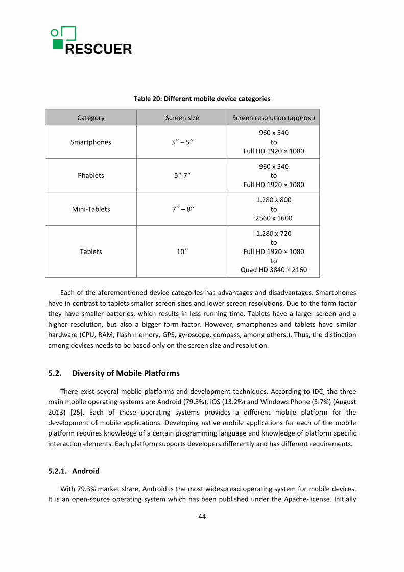
Table 20: Different mobile device categories
Category Screen size Screen resolution (approx.)
Smartphones 3‘‘ – 5‘‘ 960 x 540
to Full HD 1920 × 1080
Phablets 5“-7“ 960 x 540
to Full HD 1920 × 1080
Mini-Tablets 7‘‘ – 8‘‘ 1.280 x 800
to 2560 x 1600
Tablets 10‘‘
1.280 x 720 to
Full HD 1920 × 1080 to
Quad HD 3840 × 2160
Each of the aforementioned device categories has advantages and disadvantages. Smartphones
have in contrast to tablets smaller screen sizes and lower screen resolutions. Due to the form factor they have smaller batteries, which results in less running time. Tablets have a larger screen and a higher resolution, but also a bigger form factor. However, smartphones and tablets have similar hardware (CPU, RAM, flash memory, GPS, gyroscope, compass, among others.). Thus, the distinction among devices needs to be based only on the screen size and resolution.
5.2. Diversity of Mobile Platforms
There exist several mobile platforms and development techniques. According to IDC, the three main mobile operating systems are Android (79.3%), iOS (13.2%) and Windows Phone (3.7%) (August 2013) [25]. Each of these operating systems provides a different mobile platform for the development of mobile applications. Developing native mobile applications for each of the mobile platform requires knowledge of a certain programming language and knowledge of platform specific interaction elements. Each platform supports developers differently and has different requirements.
5.2.1. Android
With 79.3% market share, Android is the most widespread operating system for mobile devices. It is an open-source operating system which has been published under the Apache-license. Initially
44

developed by Andy Rubin, Android has been bought in 2005 by Google. There is a huge diversity of mobile devices with this operating system, ranging from 1.6 inch smart watches to 12 inch tablets. Table 21 gives an exemplary overview of different Android devices.
Table 21: Diversity of Android devices
Device Screen size Resolution
Samsung Galaxy Gear (Smartwatch) 1.6 inch 320 x 320
Samsung Galaxy Fame Lite 3.5 inch 320x480
HTC one m8 5 inch 1080x1920
Samsung Galaxy Mega 6.3inch 1.280x720
Samsung GALAXY Tab 3 7.0 7 inch 1024x600
Samsung GALAXY TabPro 8.4 inch 2.560x1.600
Samsung GALAXY NotePRO 12.2 inch 2560x1600
Based on the huge amount of screen sizes and resolutions as well as the resulting pixels per inch,
it is time consuming to develop a universal application that fits all sizes and resolutions or at least all smartphones and tablets. The Android operating system is licensed to several hardware vendors such as HTC or Samsung. These vendors often modify or extend the basic operating system with device specific features. The main development language used for Android is Java.
The Android architecture is based on the Linux-kernel and the Dalvik Virtual Machine (Dalvik VM), as illustrated in Figure 10.
The Linux-kernel takes care of the basic functionality, i.e., memory management, process management, network-communication and the interface for multimedia. It acts as an abstraction layer between the underlying hardware and the rest of the software. The Dalvik VM is a reduced Java Virtual Machine (JVM). Applications are written in a Java-like language and compiled to byte code. The JVM-compatible .class files are converted to Dalvik-compatible .dex (Dalvik Executable) files before installation on a device. The Dalvik Executable format is more compact and especially designed for systems with low memory and processor speed such as mobile devices. Furthermore, the Dalvik VM uses a register-based architecture instead of JVM’s stack machine architecture. This reduces the number of instructions to load data on the stack, but it increases the length of the instructions, because source and destination registers need to be encoded within them. The debate about which architecture is faster has not been decided yet. According to Google, the Dalvik VM is designed so that multiple instances of it can run efficiently on one device. This way, each executed application runs in its own VM.
45
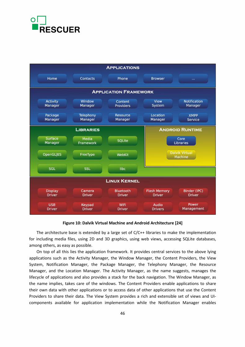
Figure 10: Dalvik Virtual Machine and Android Architecture [24]
The architecture base is extended by a large set of C/C++ libraries to make the implementation for including media files, using 2D and 3D graphics, using web views, accessing SQLite databases, among others, as easy as possible.
On top of all this lies the application framework. It provides central services to the above lying applications such as the Activity Manager, the Window Manager, the Content Providers, the View System, Notification Manager, the Package Manager, the Telephony Manager, the Resource Manager, and the Location Manager. The Activity Manager, as the name suggests, manages the lifecycle of applications and also provides a stack for the back navigation. The Window Manager, as the name implies, takes care of the windows. The Content Providers enable applications to share their own data with other applications or to access data of other applications that use the Content Providers to share their data. The View System provides a rich and extensible set of views and UI-components available for application implementation while the Notification Manager enables
46

developers to display custom alerts of their application in the status bar. The Package Manager provides methods for querying and manipulating installed packages and related permissions. The Telephony Manager provides a complete environment for developers to use phone-calls and messaging. The Resource Manager grants access to non-code resources such as localized (language specific) strings, graphics, and layout files. Finally, the Location Manager gives the developer access to the GPS module. The roof of the whole architecture is formed by the core applications shipped with Android, e.g. email client, SMS program, calendar, maps, browser, contacts, among others. The architecture of Android is designed so that every new application can make use of every core application and even replace them totally [19].
The Android SDK (software development kit) comes along with Eclipse and the Android Developer Tools Plugin, as well as the Android system emulator. For development based on the Android platform, Google provides a huge amount of API guides, references, tools, sample code, style guides, among others.
In order to extend the smartphones functionality, apps can be downloaded from Google’s own app store, the Play Store, or app stores from different 3rd party vendors such as amazon or directly from the web.
Furthermore, Android has security features built into the operating system that significantly reduce the frequency and impact of application security issues. The system is designed to allow building apps with default system and file permissions and avoid difficult decisions about security. The Android Application Sandbox isolates app data and code execution from other apps [21]. In addition to running applications in the Sandbox, it is also possible to give root access to applications in order to bypass these security aspects. This leads to less constraints and more freedom, but also implies in security risks from the user’s perspective.
5.2.2. iOS
Firstly known as iPhone OS, iOS is a mobile operating system developed by Apple for the iPhone, iPad, iPod touch and AppleTV. Although the first iOS was released one year upfront Android, its market share is only 13.2%. In contrast to Android, Apple does not license iOS to hardware vendors, which results in the fact that there is a very limited amount of different devices on the market running iOS. Table 22 summarizes all available iOS devices currently sold by Apple.
From the development perspective, there are two different screen sizes/resolutions for smartphones to take into consideration and three different screen sizes/resolutions for tablets. This implies in less effort for UI adjustment.
47

Table 22: All available iOS devices
Device Screen size Resolution
iPhone 4s 3.5 inch 960 x 640
iPhone 5s/5c, iPod touch 4 inch 1136 x 640
iPad mini 7.9 inch 1024 x 768
iPad mini/retina 7.9 inch 2048 x 1536
iPad retina/air 9.7 inch 2048 x 1536
iOS is derived from Mac OS X and therefore is also a UNIX-based operating system. The
architecture of iOS (Figure 11) consists of the four layers, namely Cocoa Touch, Media Services, Core Services, and Core OS [22].
Figure 11: iOS Architecture [22]
The Core OS layer builds the abstraction from the hardware and is realized through a modified mach-kernel. The functionality of this layer reaches from network functionality with the CFNetwork Framework, over access to external accessories with the External Accessory Framework, to common, fundamental operating system functionalities, such as security, memory management, file system management, and threads. The Core Services layer is the next abstraction level. It delivers important functionality to the layers above, such as database functionality with the SQLite library (respective CoreData), transactions between applications with the Store Kit Framework, database management with the Core Data Framework, among others. The next layer is the Media Services layer. It provides audio through the AV Foundation Framework, video through the Media Player Framework, and
48

graphics functionality through the OpenGL ES Framework, in addition to two-dimensional drawing through the Core Graphics Framework and the animation of such drawings through the Quartz Core Framework. The Cocoa Touch layer is the top layer and therewith the most important one for software developers. It is mostly written in Objective-C and based on the Cocoa API of Mac OS X with specializations for the iPhone. It offers many of the core frameworks needed by developers, such as the UIKit Framework, the Map Kit Framework, the Push Notification Service, the Message UI Framework, the Address Book UI Framework, and the Game Kit Framework. The UIKit Framework is a big, functionality-rich, Objective-C based API which contains the majority of the functionalities most commonly used by iOS developers. The most important functions are: creation and management of UI elements, handling of program-cycles and events, data handling, inter process communication (IPC), and usage of data from hardware like accelerometer, battery, gyroscope, camera, and others. The Map Kit Framework delivers the functionality for map-based applications, such as the scrolling of a map, the overlaying of a map with additional information, the presentation of a map in accordance to the actual geographical position of the device. The Push Notification Service gives the opportunity to inform the user about an event without the need for the respective application to be active. In iOS, messages take an extra tour over an Apple server and are sent by the Push Notification Service. This way only one process has to run in the background, instead of having all applications running in the background and listening for their push notifications like in Android. The Message UI Framework gives the possibility to send e-mails from any arbitrary application and even provides the UI elements needed for this task. The Address Book UI Framework contains the functionalities to access the address book, and to show and edit both address and contact information. The Game Kit Framework allows peer-to-peer connections between several different devices. Its name derives from the fact that it was meant for the implementation of multiplayer games [19].
Each iOS application runs in its own sandbox resulting in the fact there is no direct access to the hardware (file system, network, etc.). Applications cannot access the data of other applications. Hardware and software can only be accessed via designated APIs, which gives the user the control to manually decide which application may have access to which features (GPS, Push, Calendar, Contacts, etc.). There exist mechanisms to exchange data between applications but they are very limited. If a major data exchange between applications needs to be established, this must be done over the internet via a cloud or similar approach.
Apple provides its own integrated development kit (IDE) XCode to natively develop iOS applications. Xcode comes along with a code editor, iOS simulator, tools to analyse the app and to submit it to the app store. In contrast to Android, the only possibility to download apps is through Apple’s app store. Every app undergoes Apples’s own review process before being released in the app store. By doing so, Apple ensures a certain level of quality of the apps released in its app store but, on the other hand, limits the freedom of developers and the applications. For example, it is not possible to run huge tasks in the background, extensively track/use sensor data, or continuously perform certain actions.
49

5.2.3. Windows Phone
Windows Phone is a mobile operating system developed by Microsoft for smartphones (market share 3.7%). The equivalent tablet operating system is called Windows RT. Like Windows 8, both systems are based on the Windows-NT kernel. In 2015, Microsoft plans to merge the smartphone and tablet platforms. Similar to Google, Microsoft licenses its operating system to hardware vendors which sell their devices with Windows Phone/RT. Table 23 gives an overview of several devices available for Windows Phone and Windows RT.
Table 23: Windows Phone/RT device diversity
Device Screen size Resolution Operating System
HTC 8XT 4.3 inch 800 x 480 Windows Phone
Nokia Lumia 930 5 inch 1920 x 1080 Windows Phone
Nokia Lumia 1520 6 inch 1920 x 1080 Windows Phone
Acer Iconia W4-820 8 inch 1280 x 800 Windows RT 8.1
Nokia Lumia 2520 10.1 inch 1920 x 1080 Windows RT 8.1
Microsoft wanted to have similar functionality as iOS and Android in Windows Phone, but also
wanted to avoid the risk of getting mixed up with them. Therefore, they decided for a completely different look, as all other mobile operating systems looked quite alike. The home screen, called start screen, of Windows Phone consists of so called tiles. Tiles are rectangular, clickable areas that represent links to applications, features, functions, and individual items. The users are free to add, rearrange, or remove these tiles. They are dynamic and are updated in real time. The main architecture of Windows Phone 8 is built up of four layers (Figure 12).
The lowest layer is the Hardware Foundation layer. Similarly to Android and iOS, it abstracts from the hardware and provides access to it for the above lying layers. The second lowest layer is the Kernel layer. It consists of a Windows kernel which takes care of security, networking, and storage issues. It also manages the device resources and grants the above lying layers access through drivers to the hardware abstractions delivered by the Hardware Foundation layer. The layer on top of these two contains the three pillars: App Model, UI Model, and Cloud Integration. The App Model is responsible for the management, the licensing, the run-time isolation, and the updating of the applications. The UI Model takes care of visualization tasks, such as session management, rendering of the different UI layers onto the screen with Direct3D, and switching between windows. It also provides the possibility to open an application from another application to allow a fluent navigation between the applications. The third pillar – Cloud Integration – attends to the services supplied by the internet, which includes Xbox Live, Bing, push notifications, Windows Live, among others. The
50

layer over these three important pillars is the Application platform. It builds the platform for application developers to develop three different types of applications, namely Silverlight, XNA, and HTML/JavaScript. Silverlight applications are meant for business purposes. XNA is the basis for games. These two application types built on the Common Language Run-Time (CLR). The last application type consists of web applications that run inside the web browser. All three application types make use of frameworks to deliver access to hardware and services [19].
Figure 12: Windows Phone Architecture [23]
There exist several ways to develop native apps for Windows Phone. Based on a specialized .NET API, it is possible to develop apps in C# or Visual Basic and Silverlight. Windows Phone Runtime (WinPRT) provides the basic functionalities of Windows RT based on native COM-components. Wrappers provide the functionality to call the runtime environment with .NET C#/VB and native C++. For developing the apps, Microsoft provides Visual Studio 2013, Blend for Visual Studio, the Windows Phone 8 SDK as well as a Windows Phone Emulator.
Windows Phone apps run in a sandboxed process. This means that they are isolated from each other, and will interact with phone features in a strictly structured way. If an app needs to save data or configuration information, it will do so using isolated storage, which is designed to be protected
51
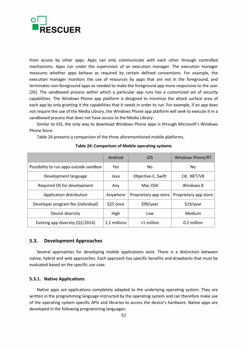
from access by other apps. Apps can only communicate with each other through controlled mechanisms. Apps run under the supervision of an execution manager. The execution manager measures whether apps behave as required by certain defined conventions. For example, the execution manager monitors the use of resources by apps that are not in the foreground, and terminates non-foreground apps as needed to make the foreground app more responsive to the user [26]. The sandboxed process within which a particular app runs has a customized set of security capabilities. The Windows Phone app platform is designed to minimize the attack surface area of each app by only granting it the capabilities that it needs in order to run. For example, if an app does not require the use of the Media Library, the Windows Phone app platform will seek to execute it in a sandboxed process that does not have access to the Media Library.
Similar to iOS, the only way to download Windows Phone apps is through Microsoft’s Windows Phone Store.
Table 24 presents a comparison of the three aforementioned mobile platforms.
Table 24: Comparison of Mobile operating systems
Android iOS Windows Phone/RT
Possibility to run apps outside sandbox Yes No No
Development language Java Objective-C, Swift C#, .NET/VB
Required OS for development Any Mac OSX Windows 8
Application distribution Anywhere Proprietary app store Proprietary app store
Developer program fee (individual) $25 once $99/year $19/year
Device diversity High Low Medium
Existing app diversity (Q1/2014) 1.2 millions >1 million 0.2 million
5.3. Development Approaches
Several approaches for developing mobile applications exist. There is a distinction between native, hybrid and web approaches. Each approach has specific benefits and drawbacks that must be evaluated based on the specific use case.
5.3.1. Native Applications
Native apps are applications completely adapted to the underlying operating system. They are written in the programming language instructed by the operating system and can therefore make use of the operating system specific APIs and libraries to access the device’s hardware. Native apps are developed in the following programming languages:
52
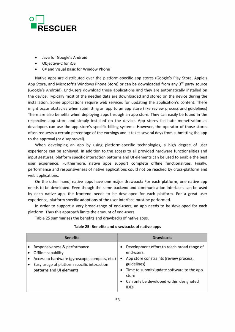
• Java for Google’s Android • Objective-C for iOS • C# and Visual Basic for Window Phone
Native apps are distributed over the platform-specific app stores (Google’s Play Store, Apple’s App Store, and Microsoft’s Windows Phone Store) or can be downloaded from any 3rd party source (Google’s Android). End-users download these applications and they are automatically installed on the device. Typically most of the needed data are downloaded and stored on the device during the installation. Some applications require web services for updating the application’s content. There might occur obstacles when submitting an app to an app store (like review process and guidelines) There are also benefits when deploying apps through an app store. They can easily be found in the respective app store and simply installed on the device. App stores facilitate monetization as developers can use the app store’s specific billing systems. However, the operator of those stores often requests a certain percentage of the earnings and it takes several days from submitting the app to the approval (or disapproval).
When developing an app by using platform-specific technologies, a high degree of user experience can be achieved. In addition to the access to all provided hardware functionalities and input gestures, platform specific interaction patterns and UI elements can be used to enable the best user experience. Furthermore, native apps support complete offline functionalities. Finally, performance and responsiveness of native applications could not be reached by cross-platform and web applications.
On the other hand, native apps have one major drawback: For each platform, one native app needs to be developed. Even though the same backend and communication interfaces can be used by each native app, the frontend needs to be developed for each platform. For a great user experience, platform specific adoptions of the user interface must be performed.
In order to support a very broad-range of end-users, an app needs to be developed for each platform. Thus this approach limits the amount of end-users.
Table 25 summarizes the benefits and drawbacks of native apps.
Table 25: Benefits and drawbacks of native apps
Benefits Drawbacks
• Responsiveness & performance • Offline capability • Access to hardware (gyroscope, compass, etc.) • Easy usage of platform specific interaction
patterns and UI elements
• Development effort to reach broad range of end-users
• App store constraints (review process, guidelines)
• Time to submit/update software to the app store
• Can only be developed within designated IDEs
53

5.3.2. Mobile Web Pages
Mobile web pages are websites that are accessible through the browser of the specific smartphone and tablet. Mobile web pages display requested information optimized for the devices screen size and resolution. Based on responsive web design techniques, the website is developed once and automatically adjusts to the characteristics of the device. An alternative is to develop different websites for each device class such as smartphones, tablets, and desktops, which is done when the goal is to have completely different look-and-feels on the corresponding devices. Apart from supporting different device classes, mobile websites can also support platform specific characteristics such as button appearances, screen transition behaviour, among others.
When developing mobile websites common internet standards such as HTML, PHP, CSS, and JavaScript are used. The website is then deployed on a webserver and is accessible via every browser. This way they do not undergo the review process in app stores which increases time to market as well as updateability.
However, in contrast to native applications, this approach lowers user experience. Websites and their performance strongly depend on the available internet connection. Especially in the mobile domain, working and fast internet connections cannot be assumed and therefore long loading times may appear. Furthermore, it is not possible to have access to all hardware features provided by the smartphone. Web-languages do not support hardware-sensors like the gyroscope, NFC, or temperature. In addition, native input modalities like swipe gestures or multi touch are not supported, as browsers on smartphones mainly support scrolling and pan&zoom.
Thus the strengths of mobile web pages are mainly to support a very broad range of end-users using heterogeneous devices. Despite the user experience of such web pages being very low in contrast to other approaches, the results are still acceptable and are improving more and more due to continuous enhancements in the web domain.
Table 26 summarizes the benefits and drawbacks of mobile web pages.
Table 26: Benefits and drawbacks of mobile web pages
Benefits Drawbacks
• Usage of open web standards • Independent of app stores • Cross platform • Shorter time to market • Easier maintenance • UI responsiveness & performance
• Lowered/bad user experience • Slow due to huge data transmissions • Only available with working internet
connection • Very limited access to hardware sensors • No access to software APIs (contacts,
calendar, etc.)
54
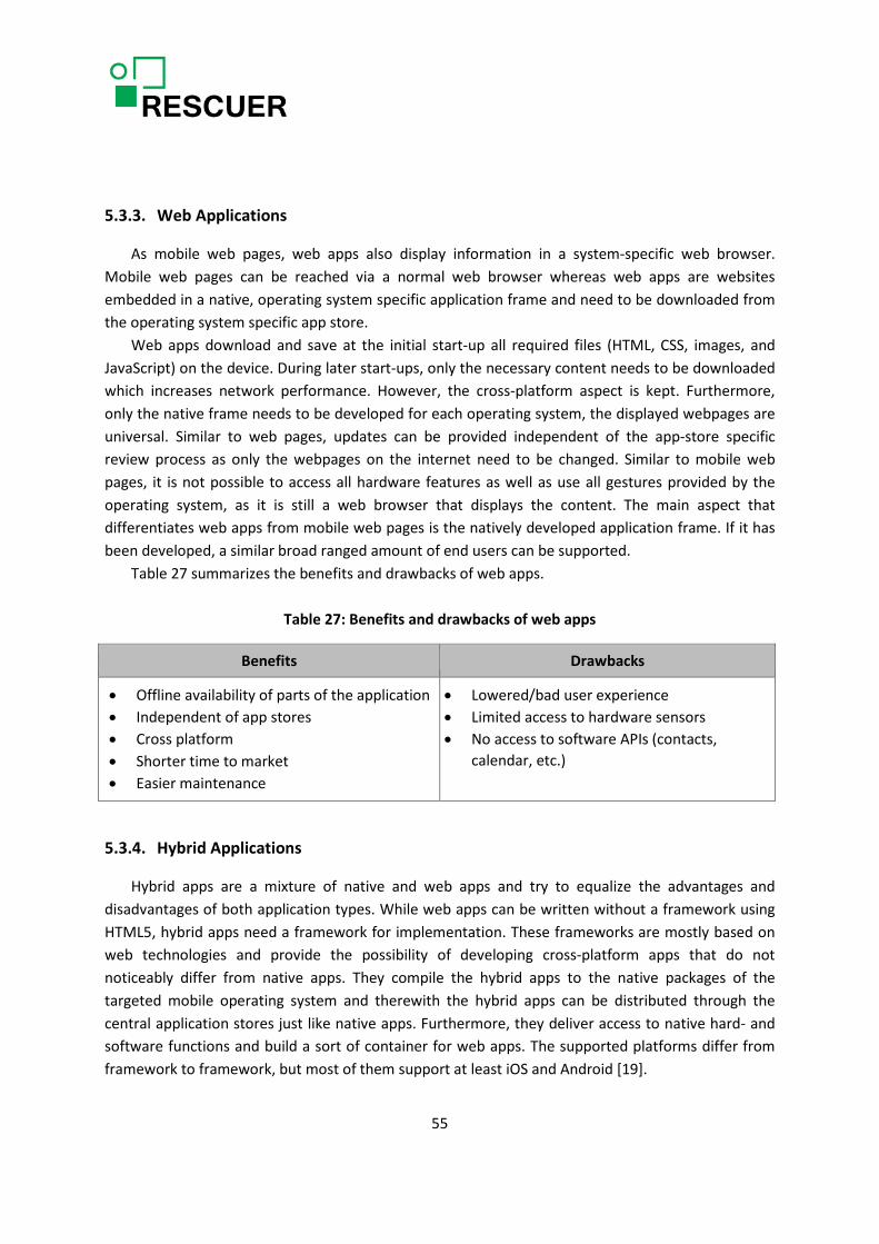
5.3.3. Web Applications
As mobile web pages, web apps also display information in a system-specific web browser. Mobile web pages can be reached via a normal web browser whereas web apps are websites embedded in a native, operating system specific application frame and need to be downloaded from the operating system specific app store.
Web apps download and save at the initial start-up all required files (HTML, CSS, images, and JavaScript) on the device. During later start-ups, only the necessary content needs to be downloaded which increases network performance. However, the cross-platform aspect is kept. Furthermore, only the native frame needs to be developed for each operating system, the displayed webpages are universal. Similar to web pages, updates can be provided independent of the app-store specific review process as only the webpages on the internet need to be changed. Similar to mobile web pages, it is not possible to access all hardware features as well as use all gestures provided by the operating system, as it is still a web browser that displays the content. The main aspect that differentiates web apps from mobile web pages is the natively developed application frame. If it has been developed, a similar broad ranged amount of end users can be supported.
Table 27 summarizes the benefits and drawbacks of web apps.
Table 27: Benefits and drawbacks of web apps
Benefits Drawbacks
• Offline availability of parts of the application • Independent of app stores • Cross platform • Shorter time to market • Easier maintenance
• Lowered/bad user experience • Limited access to hardware sensors • No access to software APIs (contacts,
calendar, etc.)
5.3.4. Hybrid Applications
Hybrid apps are a mixture of native and web apps and try to equalize the advantages and disadvantages of both application types. While web apps can be written without a framework using HTML5, hybrid apps need a framework for implementation. These frameworks are mostly based on web technologies and provide the possibility of developing cross-platform apps that do not noticeably differ from native apps. They compile the hybrid apps to the native packages of the targeted mobile operating system and therewith the hybrid apps can be distributed through the central application stores just like native apps. Furthermore, they deliver access to native hard- and software functions and build a sort of container for web apps. The supported platforms differ from framework to framework, but most of them support at least iOS and Android [19].
55

Hybrid or web-to-native wrapper frameworks build an appendix for the existing web apps. The web app is bound to a web view in a native app. In this way a web app can be compiled to a native app without any changes in the code (see subsection 5.3.3).
On the other hand, apps of cross-compiled or source code translator frameworks are written in a common used programming language. The written code is then cross-compiled to native code with a code generator, which is a cross-platform compiler. This provides an abstraction from the programming language of the mobile operating system. There exist several vendors of such frameworks that support cross platform development. Hybrid apps in general have access to many available hardware sensors and provide device specific gestures to interact with the application. However, the more hardware sensors and platform specific APIs are used, the more native components need to be used and thus the less hybrid the apps are.
Another aspect to consider is that, after major operating system updates, it often takes time until vendors have updated their wrapper frameworks to make them compatible to the new version of the operating system. Furthermore, Xcode is still needed to submit iOS applications to the app store.
Hybrid apps are deployed via the specific app stores, which has its advantages and disadvantages (review process, monetization, and guidelines, among others).
Table 28 summarizes the benefits and drawbacks of hybrid apps.
Table 28: Benefits and drawbacks of hybrid apps
Benefits Drawbacks
• Offline capability • (limited) Access to hardware features • Usage of platform specific interaction
patterns and UI elements (depending on the framework)
• Cross platform
• Another language/framework to get used to • Less responsive than native apps • App store constraints (review process,
guidelines, time to submit/update an app) • Time to adapt frameworks to new operating
system updates
5.3.5. Guidelines for Developing Mobile Applications
There is not one right way to develop mobile applications. The selection of the development approach strongly depends on the context within the application is intend to be used, its users, the development effort to be spent, the concrete requirements (e.g. whether it is necessary to have access to hardware sensors and/or software APIs, among others.) and other further factors. Table 29 provides decision support for selecting the appropriate development approach. There are mainly seven decision categories to be considered, namely user experience, usage of device features, multi-platform support, required tools/skills, speed, costs, and delivery method.
56

From the user experience perspective, the native approach is obviously the way to go. Native UI elements, gestures, offline capability, and performance satisfy the user in the best possible way. Hybrid approaches support all these features to a certain degree, whereas web approaches have deficits in performance, offline capability, gestures, and look&feel. When developing native app, the UI design and screen flow might be developed for each operating system individually, which results in the best possible UX, but also in the most development effort. Hybrid apps support different UI designs or can share the same design. It is up to the used framework and user interface design techniques how this is taken into account. Web apps mainly share the same UI design and screen flow whereas it is already possible to make adaptive, operating system specific, web apps.
Taking the usage of device features into account, hybrid approaches support most of the device features available natively. In contrast, web apps access to device specific functions is very limited (Table 29). If access to device features respectively sensor data is needed, a hybrid or native approach must be used.
Native apps support only their respective operating system, whereas hybrid and web apps support a wide range of mobile operating systems. Taking multiple screen sizes into account, even native apps need to be adapted to support e.g. tablets and smartphones. iOS applications can share a same code-base whereas the UI is developed separately for iPhones and iPads. It is also possible to scale iPhone apps to an iPad, resulting in a magnification of the iPhone app. Web apps and hybrid frameworks like PhoneGap also support up scaling. However, it is often not feasible to only upscale applications as a larger screen may result in a different UI design and screen flow. Thus, at least the UI of smartphone and tablet applications need to be developed separately.
Available developers/required tools also have an impact on the development strategy. For going for native apps, developers must have knowledge in the concrete development languages (Java, C#, Objective-C, among others). This means that several developers are necessary, each one skilled in a specific language, or it is necessary to have available developers with a broader ranged knowledge. In addition, Windows 8 computers are necessary for Windows Phone development, whereas Macs are required for iOS development.
The development for different platforms (native) takes much longer, as for each platform an application needs to be developed separately. Hybrid and web apps are developed for all target platforms, where some adjustments need to be done for hybrid apps. This has impact and effort respective costs. Developing one application for different operating systems costs much more than developing a hybrid or web app. If there is a very limited budget, it gets very difficult to develop several apps natively.
The delivery method depends on the approach. Native and hybrid applications can be sold through the app store. The provider takes care of the accounting and also of the quality of the app. Users can be sure that apps downloaded from the app store do not harm them or their privacy. Web apps are not managed by app stores, they are simple websites accessible via browser. Thus they can be updated instantly, without a review process. Native and hybrid applications must undergo the operating system specific app store’s review process, which takes some days. After an update has
57

passed the review process, it cannot be ensured that users will download the latest version of the application.
Table 29: Decision support for Mobile Application Development [20]
Native Hybrid Web User experience Performance Fast Slower Slower UX/UI Best Similar to native app Like a website Gestures Best Possible Limited Connectivity Online and offline Online and offline Online and limited
offline Quality control High (through app
store policies) High (through app store policies)
Up to developer
Browser variability Not an issue Not an issue Can be an issue Use of device features Local storage Best Possible Limited Accelerometer Yes Yes No NFC Yes Yes No Camera integration Yes Yes Yes Calendar Yes Yes No GPS Yes Yes Yes Multi-platform support Multiple operating systems No Yes Yes Multiple screen sizes Custom Custom Automatic Tools/Skills required Dev Tools Native Platform
SDKs Frameworks, e.g. PhoneGap, Appcelerator
Frameworks, e.g. jQuery Mobile, Sencha
Developer Skills Specialized – Objective-C, Java, C#
Framework dependent plus HTML5, CSS, JS
HTML5, CSS, JS
Developer Availability Most limited Training is required Easiest transition Cost Development time Slow Faster Fastest Effort for updates/new versions Slow (iOS &
Windows), Fast (Android)
Faster Fastest
Testing Testing on each platform
Testing on each platform
Testing with multiple browsers
Code reuse Limited Better Best Delivery method Marketing/Discovery/Download App store App store Web Updates App store App store None required Flexibility Limited Limited High
58

Native Hybrid Web Other considerations Security High High Weaker Data management High High Depending on the
used technology
59

6. First Concept of the Portability & VM Strategy This chapter is concerned with providing the guidelines for dealing with variability in the
RESCUER project. It decides on the variability modelling approach to be used in the project, provides recommendations regarding the most suitable realization techniques for the already identified variabilities, as well as recommendations regarding the mobile application development approach to be used in the project. The RESCUER variability model is also presented in this chapter, as it is crucial to base the recommendations about the most suitable realization techniques and mobile application development approach. Furthermore, this chapter provides guidelines for capturing variability in the project’s requirements specification.
6.1. Variability Modelling Approach
Section 4.1 presented different approaches for variability modelling and discussed their strengths and weaknesses. Feature modes and its particular representation using feature diagrams is the approach selected to be used in the RESCUER project for several reasons:
• Feature diagrams support the elicitation and understanding of commonalities and variabilities with customers and/or end-users [10]. Dependencies are better visualized in feature diagrams, especially if constraints (dependencies beyond the parent relationship) are included.
• There is free software for feature modelling. • Feature diagrams can be used for modelling variability and for supporting the specification of
product variants [12]. The selection of features for a product variant can be translated into propositions and formally verified against the feature model [30].
• Several authors have proposed complementary models to the feature model in order to capture the relationships between features and the other development artifacts [28].
• Feature models are the most popular form of variability models. There is a trend towards feature-oriented software product lines engineering that can be observed in [7] and [28], for example.
• Feature diagrams are the most familiar approach for the RESCUER stakeholders and partners.
6.2. RESCUER Variability Model
This section presents the current status of the RESCUER variability model represented with feature diagrams. For presentation’s sake, the first diagram (Figure 13) provides an overview of the main features of the RESCUER platform and the following diagrams detail each of these main features.
60

The feature diagrams for the Mobile Crowdsourcing Solution, Emergency Response Toolkit, and Data Processing features are provided in Figure 14, Figure 15, and Figure 16, respectively, whereas their respective feature specifications are provided in Table 30, Table 31, and Table 32. Figure 17 provides the feature diagram for the remaining RESCUER features, while Table 33 contains the respective feature specifications.
Figure 13: RESCUER platform overview
61

Figure 14: Feature Model of the Mobile Crowdsourcing Solution (Iteration 1)
62
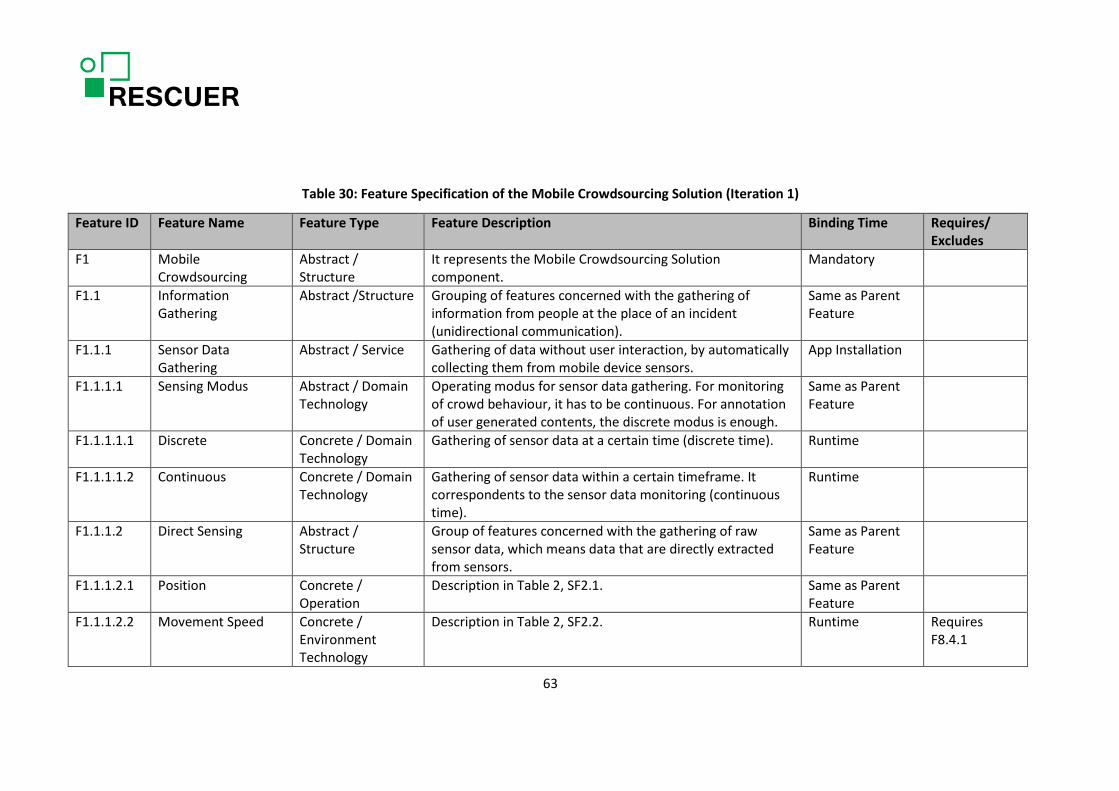
Table 30: Feature Specification of the Mobile Crowdsourcing Solution (Iteration 1)
Feature ID Feature Name Feature Type Feature Description Binding Time Requires/ Excludes
F1 Mobile Crowdsourcing
Abstract / Structure
It represents the Mobile Crowdsourcing Solution component.
Mandatory
F1.1 Information Gathering
Abstract /Structure Grouping of features concerned with the gathering of information from people at the place of an incident (unidirectional communication).
Same as Parent Feature
F1.1.1 Sensor Data Gathering
Abstract / Service Gathering of data without user interaction, by automatically collecting them from mobile device sensors.
App Installation
F1.1.1.1 Sensing Modus Abstract / Domain Technology
Operating modus for sensor data gathering. For monitoring of crowd behaviour, it has to be continuous. For annotation of user generated contents, the discrete modus is enough.
Same as Parent Feature
F1.1.1.1.1 Discrete Concrete / Domain Technology
Gathering of sensor data at a certain time (discrete time). Runtime
F1.1.1.1.2 Continuous Concrete / Domain Technology
Gathering of sensor data within a certain timeframe. It correspondents to the sensor data monitoring (continuous time).
Runtime
F1.1.1.2 Direct Sensing Abstract / Structure
Group of features concerned with the gathering of raw sensor data, which means data that are directly extracted from sensors.
Same as Parent Feature
F1.1.1.2.1 Position Concrete / Operation
Description in Table 2, SF2.1. Same as Parent Feature
F1.1.1.2.2 Movement Speed Concrete / Environment Technology
Description in Table 2, SF2.2. Runtime Requires F8.4.1
63

Feature ID Feature Name Feature Type Feature Description Binding Time Requires/ Excludes
F1.1.1.2.3 Movement Direction Concrete / Environment Technology
Description in Table 2, SF2.3. Runtime Requires F8.4.1
F1.1.1.2.4 Altitude Concrete / Operation
Description in Table 2, SF2.4. App Installation
F1.1.1.2.4.1.
Altitude from Sensor Concrete / Environment Technology
Gathering of altitude data from a specific sensor or using GPS coordinates (direct sensing). It is not relevant to F1, but it is relevant for supporting multimedia data analysis.
Same as Parent Feature
RequiresF8.5
F1.1.1.2.4.2
Altitude from GPS Concrete / Environment Technology
Gathering of altitude data using GPS coordinates. Runtime Requires F8.4.1
F1.1.1.2.5 Device Acceleration Concrete / Environment Technology
Gathering of data from the accelerometer. Same as Parent Feature
F1.1.1.2.6 Gyroscope Orientation
Concrete / Environment Technology
Gathering of data from the gyroscope. Same as Parent Feature
F1.1.1.2.7 Compass Orientation Concrete / Environment Technology
Gathering of data from the compass. Same as Parent Feature
F1.1.1.2.8 Display Orientation Concrete / Environment Technology
Gathering of display orientation data. Same as Parent Feature
F1.1.1.3 Indirect Sensing Abstract / Structure
Group of features that provides data derived from raw sensor data.
64

Feature ID Feature Name Feature Type Feature Description Binding Time Requires/ Excludes
F1.1.1.3.1 Device Orientation Concrete / Domain Technology
Description in Table 2, SF2.5.
F1.1.1.3.2 Movement Track Concrete / Domain Technology
Description in Table 2, SF2.6. Requires F1.1.1.2.1
F1.1.1.4 Sensor Data Annotation
Concrete / Operation
Output of sensor data with the purpose of annotation of user generated contents like incident notifications/reports.
Same as Parent Feature
F1.1.1.5 Sensor Data Streaming
Concrete / Operation
Sensor data streaming with the purpose of crowdsensing. Runtime Requires F1.1.1.1.2
F1.1.2 User Generated Data Gathering
Abstract / Service Description in Table 2, SF5. Same as Parent Feature
F1.1.2.1 User Generated Data Type
Abstract / Structure
Group of features that allow people at the place of incident to provide information about the emergency situation through the interaction with their mobile devices.
Same as Parent Feature
F1.1.2.1.1 Very Quick Notification
Concrete / Service Description in Table 2, SF5.1. It includes just the indication of the type of the incident.
Runtime
F1.1.2.1.2 Standard Notification
Concrete / Service Extension of the very quick notification with the attachment of an image or video and some information that the user can easily selected from lists.
Runtime
F1.1.2.1.3 Incident Report Concrete / Service The main characteristic is the possibility of fully describing the incident.
Runtime
F1.1.2.2 User Generated Data Source
Abstract / Structure
Group of features that indicate the level of detail of the user generated data, taking into consideration the role of the user (user profile) in emergency situations
Same as Parent Feature
65

Feature ID Feature Name Feature Type Feature Description Binding Time Requires/ Excludes
F1.1.2.2.1 Crowd Generated Data
Concrete / Service Description in Table 2, SF6.1.1. App Installation Requires F5.2.2 or F5.2.3 or F5.2.4
F1.1.2.2.2 Expert Generated Data
Concrete / Service Description in Table 2, SF6.1.2. App Installation Requires F5.2.1
F1.1.3 Multimedia Attachment
Concrete / Operation
Description in Table 2, SF7. Same as Parent Feature
F1.1.4 Soft Data Annotation Concrete / Operation
Annotation of sensor data or content explicitly generated by the user with device ID and timestamp.
Same as Parent Feature
66

Figure 15: Feature Model of the Emergency Response Toolkit (Iteration 1) 67
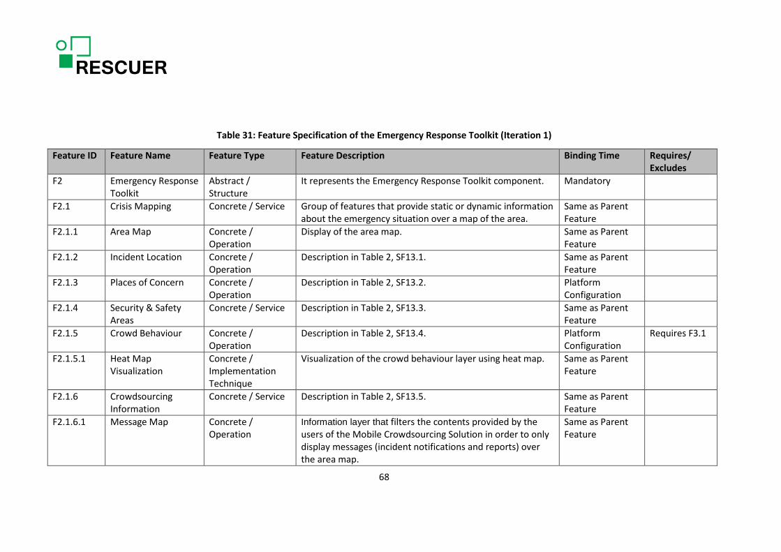
Table 31: Feature Specification of the Emergency Response Toolkit (Iteration 1)
Feature ID Feature Name Feature Type Feature Description Binding Time Requires/ Excludes
F2 Emergency Response Toolkit
Abstract / Structure
It represents the Emergency Response Toolkit component. Mandatory
F2.1 Crisis Mapping Concrete / Service Group of features that provide static or dynamic information about the emergency situation over a map of the area.
Same as Parent Feature
F2.1.1 Area Map Concrete / Operation
Display of the area map. Same as Parent Feature
F2.1.2 Incident Location Concrete / Operation
Description in Table 2, SF13.1. Same as Parent Feature
F2.1.3 Places of Concern Concrete / Operation
Description in Table 2, SF13.2. Platform Configuration
F2.1.4 Security & Safety Areas
Concrete / Service Description in Table 2, SF13.3. Same as Parent Feature
F2.1.5 Crowd Behaviour Concrete / Operation
Description in Table 2, SF13.4. Platform Configuration
Requires F3.1
F2.1.5.1 Heat Map Visualization
Concrete / Implementation Technique
Visualization of the crowd behaviour layer using heat map. Same as Parent Feature
F2.1.6 Crowdsourcing Information
Concrete / Service Description in Table 2, SF13.5. Same as Parent Feature
F2.1.6.1 Message Map Concrete / Operation
Information layer that filters the contents provided by the users of the Mobile Crowdsourcing Solution in order to only display messages (incident notifications and reports) over the area map.
Same as Parent Feature
68

Feature ID Feature Name Feature Type Feature Description Binding Time Requires/ Excludes
F2.1.6.2 Photo Map Concrete / Operation
Information layer that filters the contents provided by the users of the Mobile Crowdsourcing Solution in order to only display photos over the area map.
Platform Configuration
F2.1.6.3 Video Map Concrete / Operation
Information layer that filters the contents provided by the users of the Mobile Crowdsourcing Solution in order to only display videos over the area map.
Platform Configuration
F2.1.7 Free Drawing Concrete / Operation
Description in Table 2, SF13.6. Platform Configuration
F2.2 Crisis Dashboard Concrete / Service It presents key and official information that describes the incident, which includes incident time and incident keyword (e.g. gas leak or fire/explosion).
Same as Parent Feature
F2.2.1 Classification of Severity
Concrete / Service It presents the classification of the severity of the emergency situation. It only applies to incidents in industrial areas.
Platform Configuration
F2.2.2 Incident Counting Concrete / Service It presents the incident counter, as an emergency situation might have several incidents. Incidents are defined by the clustering of notifications/reports based on time, keyword, and location.
Platform Configuration
Requires F3.3
F2.2.3 People Counting Concrete / Service Group of several counters related to people damage. Platform Configuration
F2.2.3.1 Estimated Total Concrete / Operation
Record and display of the estimated total number of people at the event.
Same as Parent Feature
F2.2.3.2 Injured Counter Concrete / Operation
Record and display of the estimated number of injured people.
Same as Parent Feature
69
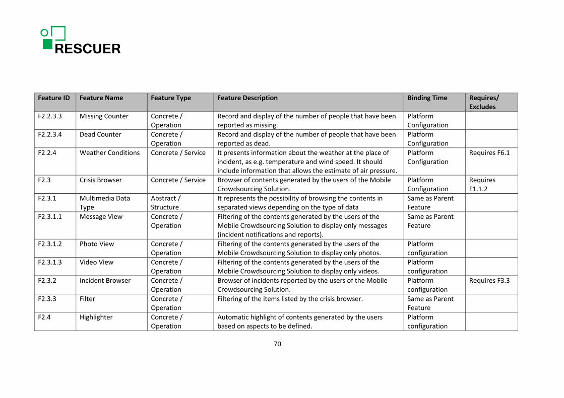
Feature ID Feature Name Feature Type Feature Description Binding Time Requires/ Excludes
F2.2.3.3 Missing Counter Concrete / Operation
Record and display of the number of people that have been reported as missing.
Platform Configuration
F2.2.3.4 Dead Counter Concrete / Operation
Record and display of the number of people that have been reported as dead.
Platform Configuration
F2.2.4 Weather Conditions Concrete / Service It presents information about the weather at the place of incident, as e.g. temperature and wind speed. It should include information that allows the estimate of air pressure.
Platform Configuration
Requires F6.1
F2.3 Crisis Browser Concrete / Service Browser of contents generated by the users of the Mobile Crowdsourcing Solution.
Platform Configuration
Requires F1.1.2
F2.3.1 Multimedia Data Type
Abstract / Structure
It represents the possibility of browsing the contents in separated views depending on the type of data
Same as Parent Feature
F2.3.1.1 Message View Concrete / Operation
Filtering of the contents generated by the users of the Mobile Crowdsourcing Solution to display only messages (incident notifications and reports).
Same as Parent Feature
F2.3.1.2 Photo View Concrete / Operation
Filtering of the contents generated by the users of the Mobile Crowdsourcing Solution to display only photos.
Platform configuration
F2.3.1.3 Video View Concrete / Operation
Filtering of the contents generated by the users of the Mobile Crowdsourcing Solution to display only videos.
Platform configuration
F2.3.2 Incident Browser Concrete / Operation
Browser of incidents reported by the users of the Mobile Crowdsourcing Solution.
Platform configuration
Requires F3.3
F2.3.3 Filter Concrete / Operation
Filtering of the items listed by the crisis browser. Same as Parent Feature
F2.4 Highlighter Concrete / Operation
Automatic highlight of contents generated by the users based on aspects to be defined.
Platform configuration
70
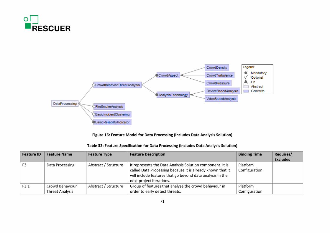
Figure 16: Feature Model for Data Processing (includes Data Analysis Solution)
Table 32: Feature Specification for Data Processing (includes Data Analysis Solution)
Feature ID Feature Name Feature Type Feature Description Binding Time Requires/ Excludes
F3 Data Processing Abstract / Structure It represents the Data Analysis Solution component. It is called Data Processing because it is already known that it will include features that go beyond data analysis in the next project iterations.
Platform Configuration
F3.1 Crowd Behaviour Threat Analysis
Abstract / Structure Group of features that analyse the crowd behaviour in order to early detect threats.
Platform Configuration
71

Feature ID Feature Name Feature Type Feature Description Binding Time Requires/ Excludes
F3.1.1 Crowd Aspect Abstract / Structure Group of features that gives the crowd behaviour aspects that the RESCUER platform should be able to analyse
F3.1.1.1 Crowd Density Concrete / Service Description in Table 2, SF10. Runtime F3.1.1.2 Crowd Turbulence Concrete / Service Description in Table 2, SF11. Runtime F3.1.1.3 Crowd Pressure Concrete / Service Description in Table 2, SF12. Runtime F3.1.2 Analysis Technology Abstract /Structure Group of features that gives the technologies that the
RESCUER platform will exploit to analyse crowd behaviour.
F3.1.2.1 Device Based Analysis
Concrete / Domain Technology
Crowd behaviour threat analysis based on the number of smart phones or other mobile devices in the area of interest.
Runtime Requires F1.1.1.2.1, F1.1.1.2.2, and F1.1.1.2.3
F3.1.2.2 Video Based Analysis Concrete / Domain Technology
Crowd behaviour threat analysis based on the analysis of the videos sent by users in the emergency situation area.
Runtime Requires F1.1.3, F1.1.4, and F1.1.1.4
F3.2 Fire/Smoke Analysis Concrete / Service Analysis of the fire/smoke spread speed using videos sent by users in the emergency situation area.
Platform Configuration
Requires F1.1.3, F1.1.4, and F1.1.1.4
F3.3 Basic Incident Clustering
Concrete / Operation Feature that cluster incident notification or reports based on time, keyword, and location.
Platform Configuration
F3.4 Basic Reliability Indicator Calculation
Concrete / Operation Feature that cluster incident notification or reports based on time, keyword, and location.
Same as Parent Feature
72

Figure 17: Feature Model for Support Infrastructure
73

Table 33: Feature Specification for Support Infrastructure
Feature ID Feature Name Feature Type Feature Description Binding Time Requires/ Excludes
F4. Communication Infrastructure
Abstract It represents the Communication Infrastructure component.
Mandatory
F4.1 Network Connection Abstract / Service Group of features that provides the possible alternatives for exchanging data between the Mobile Crowdsourcing Solution and the RESCUER server.
Same as Parent Feature
F4.1.1 Internet Concrete / Domain Technology
Default network connection. Runtime
F4.1.2 Ad-hoc Communication
Concrete / Domain Technology
Network connection to be used in case of overloaded internet connection. The availability of the features of the Mobile Crowdsourcing Solution strongly decreases in this case.
Runtime
F5 User Registration Abstract / Service It requests registration information based on the registration scope, user profile, and user language.
Mandatory
F5.1 User Language Concrete / Implementation Technique
Language to be used in the interface of the platform components. This information will be directly obtained from the operating system of the mobile device for the users of the Mobile Crowdsourcing Solution.
Same as Parent Feature
F5.1.1 Portuguese Abstract / Option The language for the user interface is Portuguese. App Installation F5.1.2 German Abstract / Option The language for the user interface is German. App Installation F5.1.3 English Abstract / Option The language for the user interface is English. App Installation F5.2 User Profile Concrete / Operation It specifies the role of the user in an emergency situation. Same as Parent
Feature
74

Feature ID Feature Name Feature Type Feature Description Binding Time Requires/ Excludes
F5.2.1 Operational Force Concrete / Domain Technology
Description in Table 2, SF14.1. App Installation
F5.2.2 Employee Concrete / Domain Technology
Description in Table 2, SF14.2. App Installation
F5.2.3 Volunteer Concrete / Domain Technology
Description in Table 2, SF14.3. App Installation
F5.2.4 Crowd Concrete / Domain Technology
Description in Table 2, SF14.4. App Installation
F5.3 Registration Scope Abstract / Operation It defines the scope of the registration. Same as Parent Feature
F5.3.1 Mobile Crowdsourcing
Concrete / Domain Technology
Registration for using the Mobile Crowdsourcing Solution. It is done when downloading the application.
App Installation
F5.3.2 Emergency Response Toolkit
Concrete / Domain Technology
Registration for using the Emergency Response Toolkit. Excludes F5.2.2, F5.2.3 and F5.2.4
F6 External Services Abstract /Structure Group of features to access external services. Mandatory F6.1 Weather Service Concrete / Service It obtains from external services information about the
weather conditions. Platform Configuration
F6.2 Map Service Concrete / Service It obtains from external services the map of the area of interest.
Same as Parent Feature
F7. Quality Mechanisms Abstract / Structure Group of features concerned with quality mechanisms. Mandatory F7.1 Integration 2 Upper
Level App Concrete / Service Description in Table 2, SF8. Platform
Configuration (P2 in Table 1)
75

Feature ID Feature Name Feature Type Feature Description Binding Time Requires/ Excludes
F7.2 Incident Log Concrete / Service Log of all actions executed in the RESCUER platform with regards to a certain incident.
Same as Parent Feature
F8 Mobile Device Abstract /Structure Group of features regarding the mobile device profile that influence the Mobile Crowdsourcing Solution.
Same as Parent Feature
F8.1 Screen Size Concrete / Environment Technology
It captures the size of the mobile device screen. It is a variability defined in terms of a value reference.
Same as Parent Feature
F8.2 Screen Resolution Concrete / Environment Technology
It captures the resolution of the mobile device screen. It is a variability defined in terms of a value reference.
Same as Parent Feature
F8.3 Operating System Concrete / Environment Technology
It captures the operating system on which the Mobile Crowdsourcing Solution should be capable of running.
Same as Parent Feature
F8.3.1 Google_Android Concrete / Environment Technology
It indicates that the operating system of a specific mobile device is Android.
App Installation
F8.3.2 Apple_iOS Concrete / Environment Technology
It indicates that the operating system of a specific mobile device is IOS.
App Installation
F8.4 GPS Concrete / Environment Technology
It captures whether GPS is active or not at runtime. Same as Parent Feature
F8.4.1 Active GPS Concrete / Environment Technology
It indicates that GPS is active in a specific mobile device running the Mobile Crowdsourcing Solution.
Runtime
76

Feature ID Feature Name Feature Type Feature Description Binding Time Requires/ Excludes
F8.4.2 Inactive GPS Concrete / Environment Technology
It indicates that GPS is not active in a specific mobile device running the Mobile Crowdsourcing Solution.
Runtime
F8.5 Altitude Sensor Concrete / Environment Technology
It indicates whether a specific mobile device has altitude sensor.
App Installation
77

6.3. Recommendations Regarding Variability Realization Techniques
As presented in Section 4.2, there are many variability realization techniques and the most suitable technique for a specific variability depends on several aspects, such as binding time, developers’ experience, and learning curve. The tables in this section indicate appropriate variability realization techniques for the features described in Section 6.2 (except the mandatory and abstract ones) to the extent that is possible at this point in time. We grouped the features that are children of the same parent feature and should follow the same variability realization technique.
In order to provide guidelines of appropriate variability realization techniques for each group of features, we analysed their descriptions. In general, the adopted rationale was:
• For features with platform configuration binding time, the techniques can be parameters and version control.
• For features with binding time at app Installation, recommended techniques are parameters and design patterns.
• For features with runtime binding time, we would expect the use of parameters and design patterns or services.
In any case, the development team should make the final decision on which techniques to use taking into consideration their experience and the fact that the chosen techniques must not violate architectures decisions. In fact, they should support the architectures decisions. For example, the team can decide to use services rather than design patterns, in order to have a good coupling and interoperability.
Table 34: Realization techniques for the Mobile Crowdsourcing Solution features (Iteration 1)
Feature ID Variability Technique F1.1.1.1: Sensing Modus
• F1.1.1.1.1: Discrete • F1.1.1.1.2: Continuous
Parameters, design patterns
F1.1.1.2: Direct Sensing • F1.1.1.2.2: Movement Speed • F1.1.1.2.3: Movement Direction • F1.1.1.2.4: Altitude
o F1.1.1.2.4.1: Altitude from Sensors o F1.1.1.2.4.2: Altitude from GPS
Parameters, design patterns
F1.1.1.5: Sensor Data Streaming Parameters, design patterns F1.1.2.1: User Generated Data Type
• F1.1.2.1.1: Very Quick Notification • F1.1.2.1.2: Standard Notification • F1.1.2.1.3: Incident Report
Parameters, services
F1.1.2.2: User Generated Data Source • F1.1.2.2.1: Crowd Generated Data • F1.1.2.2.2: Expert Generated Data
Parameters, design patterns
78

Table 35: Realization techniques for the Emergency Response Toolkit features (Iteration 1)
Feature ID Variability Technique F2.1: Crisis Mapping
• F2.1.3: Places of Concern • F2.1.5: Crowd Behaviour
Parameters, Version control
F2.1.6: Crowdsourcing Information • F2.1.6.2: Photo Map • F2.1.6.3: Video Map
Parameters, Version control
F2.1.7: Free Drawing Parameters, Version control F2.2: Crisis Dashboard
• F2.2.1: Classification of Severity • F2.2.2: Incident Counting
Parameters, Version control
F2.2.3: People Counting • F2.2.3.3 Missing Counter • F2.2.3.4 Dead Counter
Pre-processors, Version control
F2.2.4: Weather Conditions Pre-processors, Version control
F2.3: Crisis Browser F2.3.1.2: Photo View F2.3.1.3: Video View
Pre-processors, Version control
F2.3.2: Incident Browser Pre-processors, Version control
F2.4: Highlighter Pre-processors, Version control
Table 36: Realization techniques for the Data Processing features (includes Data Analysis Solution)
Feature ID Variability Technique F3.1.1: Crowd Aspect
• F3.1.1.1: Crowd Density • F3.1.1.2: Crowd Turbulence • F3.1.1.3: Crowd Pressure
Parameters, services
F3.1.2: Analysis Technology • F3.1.2.1: Device Based Analysis • F3.1.2.2: Video Based Analysis
Parameters, services
F3.2: Fire/Smoke Analysis Pre-processors, Version control
F3.3: Basic Incident Clustering Pre-processors, Version control
79

Table 37: Realization techniques for the Support Infrastructure features
Feature ID Variability Technique F4.1: Network Connection
• F4.1.1: Internet • F4.1.2: Ad-hoc Communication
Parameters, design patterns
F5.1: User Language • F5.1.1: Portuguese • F5.1.2: German • F5.1.3: English
Parameters, design patterns
F5.2: User Profile • F5.2.1: Operational Force • F5.2.2: Employee • F5.2.3: Volunteer • F5.2.4: Crowd
Parameters, design patterns
F5.3: Registration Scope • F5.3.1: Mobile Crowdsourcing • F5.3.2: Emergency Response Toolkit
Services in different platforms
F6.1: Weather Service Pre-processors, Version control
F7.1: Integration 2 Upper Level App Pre-processors, Version control
F8: Mobile Device F8.1: Screen Size F8.2: Screen Resolution
Parameters, design patterns
F8.3: Operating System F8.3.1: Google_Android F8.3.2: Apple_iOS
See Section 6.4
6.4. Recommendations Regarding the Mobile Application Development Approach
Taking the features and requirements for the Mobile Crowdsourcing Solution into account, this app or set of apps must be developed in a native or hybrid way. Web apps do not provide access to sensor data which are strictly needed. Both native and hybrid approaches provide access to desired sensor data. From the performance perspective, hybrid approaches still provide sufficient performance, whereas the user experience of a native application is much better. The Mobile Crowdsourcing Solution must contain offline functionality to store reports of an emergency situation and send them when internet is available. An important aspect to consider when deciding for a hybrid approach is how to integrate libraries. On the one hand, the RESCUER app(s) will make use of custom (native) libraries provided by DFKI to access sensor data. On the other hand, its integration into large scale event apps developed by 3rd party vendors should be possible. Thus, a library must be created that can be used in native applications.
80

6.5. Recommendations for Capturing Variability in the Requirements Specification
The requirements specifications of the RESCUER project is structured in terms of use cases and free text requirements related to this use cases (D1.1.1 Requirements Specification 1). This section proposes how to deal with variability in the use case descriptions, so that this can be adopted in the next project iteration. The next version of this deliverable will include guidelines on how to deal with variability in free text requirements and use case diagrams.
The proposed approach is based on Neiva [8]. When a feature encompasses the use case, their variabilities types are the same: If the feature variability type is mandatory, then the use case variability type is mandatory; if the feature variability type is optional, alternative or OR, then the use case variability type will be variant. The specification should follow the template below:
USE CASE Use Case ID = Unique identifier of the requirement. Name = Name that represents the requirement Variability Type = Mandatory or Variant Rationale = It defines reasons for the requirement existence Description = Description about the requirement Actor(s) = It defines the actor(s) that participate in the use case Pre-Condition = State that must be true before the use case starts Post-Condition = State that must be true after the use case finishes
Main Flow = It describes in a narrative manner a typical run of a use case. It may contain variation points
ALTERNATIVE FLOW (0 .. *) Alternative Flow ID = Unique identifier of the alternative flow
Alternative Flow Steps = It describes, in term of steps, a different path from the main flow, but where nothing goes wrong
EXCEPTION FLOW (0 .. *) Exception Flow ID = Unique identifier of the exception flow
Exception Flow Steps = It describes, in term of steps, what happens when things go wrong at the system level
VARIATION POINTS (0 .. *) Variation Point ID = Unique identifier of the variation point Description = Description about the variation point Cardinality Min = It defines the minimum of variants that can be selected Cardinality Max = It defines the maximum of variants that can be selected
81

VARIANTS (1 .. *) Variant ID = Unique identifier of the variant Variant Description = Description of the variant An instantiated example of this use case template is provided below. The example is for Types to
view multimedia data, Feature 2.3.1. use case id = UC1 name = Multimedia data browser variability type = Optional rationale = Multimedia data can be accessed based on the type of data description = It represents the possibility of browsing multimedia data in separated views
depending on the type of data. actors = Members of the command centres or operational forces. preconditions = The person needs to have access to the crisis browser. post condition = ---- main flow User requests access to the crisis browser. System permits access to the crisis browser. User defines multimedia view type. [UC1.VP1] [AF1] User accesses the system through the chosen vision. [EF1] alternative flow id = AF1 User closes the crisis browser. Exception flow id = EF1 System does not permit entry to the chosen vision. An error message is shown to the user. variantion points variant point id = UC1.VP1 description = multimedia view type cardinality min = 1 max = 2 variant id = UC1.VP1.V1: Photo View variant id = UC1.VP1.V2: Video View
82

7. Conclusion This document provides a clear definition of the RESCUER platform scope (Chapter 2), which was
very useful for creating a common understanding of the project goals for the first iteration and for guiding other active tasks in this period. It also provides relevant information about the sources of variation that might affect the RESCUER platform (Chapter 3) as well as characterises the variations already identified (Section 6.2). Our decision of modelling variability with feature diagrams is justified in Section 6.1. The recommendations provided in sections 6.3 (variability realization techniques for the identified features), 6.4 (which mobile application development approach to adopt), and 6.5 (how to capture variability in requirements) are expected to support project members in selecting the most appropriate technology for achieving efficient software reuse in each specific case. They were based on our practical experience and best knowledge of the state-of-the-art in the areas of variation management (Chapter 4) and mobile applications development (Chapter5). Refinements of the models and recommendations presented in this document will for sure occur in the next project iterations for several reasons. For example, project members are going to check the recommendations in practice and provide their feedback. Moreover, several issues must be further investigated, as e.g. whether and how the differences in the Brazilian and European regulations affect the RESCUER platform. .
83
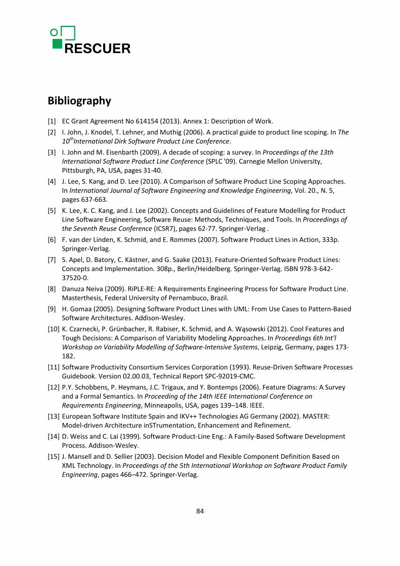
Bibliography [1] EC Grant Agreement No 614154 (2013). Annex 1: Description of Work. [2] I. John, J. Knodel, T. Lehner, and Muthig (2006). A practical guide to product line scoping. In The
10thInternational Dirk Software Product Line Conference. [3] I. John and M. Eisenbarth (2009). A decade of scoping: a survey. In Proceedings of the 13th
International Software Product Line Conference (SPLC '09). Carnegie Mellon University, Pittsburgh, PA, USA, pages 31-40.
[4] J. Lee, S. Kang, and D. Lee (2010). A Comparison of Software Product Line Scoping Approaches. In International Journal of Software Engineering and Knowledge Engineering, Vol. 20., N. 5, pages 637-663.
[5] K. Lee, K. C. Kang, and J. Lee (2002). Concepts and Guidelines of Feature Modelling for Product Line Software Engineering, Software Reuse: Methods, Techniques, and Tools. In Proceedings of the Seventh Reuse Conference (ICSR7), pages 62-77. Springer-Verlag .
[6] F. van der Linden, K. Schmid, and E. Rommes (2007). Software Product Lines in Action, 333p. Springer-Verlag.
[7] S. Apel, D. Batory, C. Kästner, and G. Saake (2013). Feature-Oriented Software Product Lines: Concepts and Implementation. 308p., Berlin/Heidelberg. Springer-Verlag. ISBN 978-3-642-37520-0.
[8] Danuza Neiva (2009). RiPLE-RE: A Requirements Engineering Process for Software Product Line. Masterthesis, Federal University of Pernambuco, Brazil.
[9] H. Gomaa (2005). Designing Software Product Lines with UML: From Use Cases to Pattern-Based Software Architectures. Addison-Wesley.
[10] K. Czarnecki, P. Grünbacher, R. Rabiser, K. Schmid, and A. Wąsowski (2012). Cool Features and Tough Decisions: A Comparison of Variability Modeling Approaches. In Proceedings 6th Int'l Workshop on Variability Modelling of Software-Intensive Systems, Leipzig, Germany, pages 173-182.
[11] Software Productivity Consortium Services Corporation (1993). Reuse-Driven Software Processes Guidebook. Version 02.00.03, Technical Report SPC-92019-CMC.
[12] P.Y. Schobbens, P. Heymans, J.C. Trigaux, and Y. Bontemps (2006). Feature Diagrams: A Survey and a Formal Semantics. In Proceeding of the 14th IEEE International Conference on Requirements Engineering, Minneapolis, USA, pages 139–148. IEEE.
[13] European Software Institute Spain and IKV++ Technologies AG Germany (2002). MASTER: Model-driven Architecture inSTrumentation, Enhancement and Refinement.
[14] D. Weiss and C. Lai (1999). Software Product-Line Eng.: A Family-Based Software Development Process. Addison-Wesley.
[15] J. Mansell and D. Sellier (2003). Decision Model and Flexible Component Definition Based on XML Technology. In Proceedings of the 5th International Workshop on Software Product Family Engineering, pages 466–472. Springer-Verlag.
84
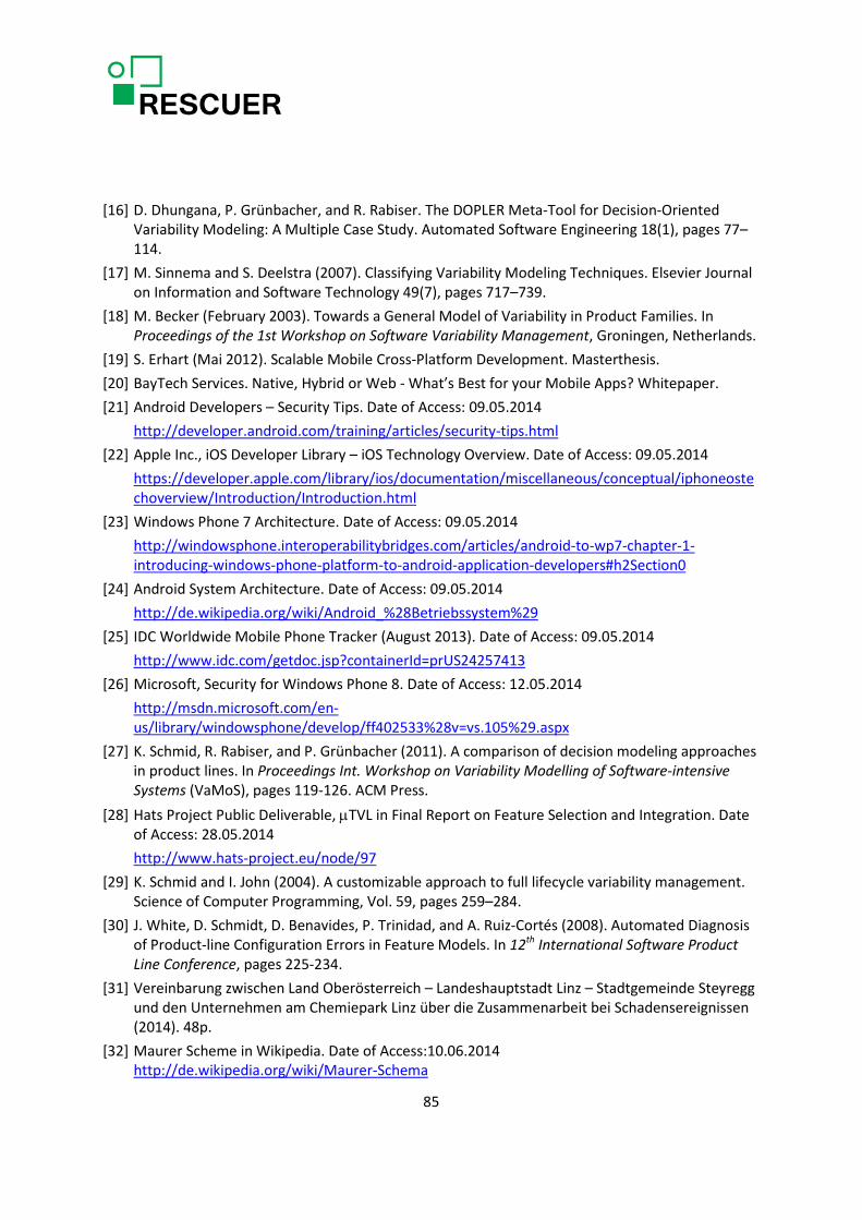
[16] D. Dhungana, P. Grünbacher, and R. Rabiser. The DOPLER Meta-Tool for Decision-Oriented Variability Modeling: A Multiple Case Study. Automated Software Engineering 18(1), pages 77–114.
[17] M. Sinnema and S. Deelstra (2007). Classifying Variability Modeling Techniques. Elsevier Journal on Information and Software Technology 49(7), pages 717–739.
[18] M. Becker (February 2003). Towards a General Model of Variability in Product Families. In Proceedings of the 1st Workshop on Software Variability Management, Groningen, Netherlands.
[19] S. Erhart (Mai 2012). Scalable Mobile Cross-Platform Development. Masterthesis. [20] BayTech Services. Native, Hybrid or Web - What’s Best for your Mobile Apps? Whitepaper. [21] Android Developers – Security Tips. Date of Access: 09.05.2014
http://developer.android.com/training/articles/security-tips.html [22] Apple Inc., iOS Developer Library – iOS Technology Overview. Date of Access: 09.05.2014
https://developer.apple.com/library/ios/documentation/miscellaneous/conceptual/iphoneostechoverview/Introduction/Introduction.html
[23] Windows Phone 7 Architecture. Date of Access: 09.05.2014 http://windowsphone.interoperabilitybridges.com/articles/android-to-wp7-chapter-1-introducing-windows-phone-platform-to-android-application-developers#h2Section0
[24] Android System Architecture. Date of Access: 09.05.2014 http://de.wikipedia.org/wiki/Android_%28Betriebssystem%29
[25] IDC Worldwide Mobile Phone Tracker (August 2013). Date of Access: 09.05.2014 http://www.idc.com/getdoc.jsp?containerId=prUS24257413
[26] Microsoft, Security for Windows Phone 8. Date of Access: 12.05.2014 http://msdn.microsoft.com/en-us/library/windowsphone/develop/ff402533%28v=vs.105%29.aspx
[27] K. Schmid, R. Rabiser, and P. Grünbacher (2011). A comparison of decision modeling approaches in product lines. In Proceedings Int. Workshop on Variability Modelling of Software-intensive Systems (VaMoS), pages 119-126. ACM Press.
[28] Hats Project Public Deliverable, µTVL in Final Report on Feature Selection and Integration. Date of Access: 28.05.2014 http://www.hats-project.eu/node/97
[29] K. Schmid and I. John (2004). A customizable approach to full lifecycle variability management. Science of Computer Programming, Vol. 59, pages 259–284.
[30] J. White, D. Schmidt, D. Benavides, P. Trinidad, and A. Ruiz-Cortés (2008). Automated Diagnosis of Product-line Configuration Errors in Feature Models. In 12th International Software Product Line Conference, pages 225-234.
[31] Vereinbarung zwischen Land Oberösterreich – Landeshauptstadt Linz – Stadtgemeinde Steyregg und den Unternehmen am Chemiepark Linz über die Zusammenarbeit bei Schadensereignissen (2014). 48p.
[32] Maurer Scheme in Wikipedia. Date of Access:10.06.2014 http://de.wikipedia.org/wiki/Maurer-Schema
85

Glossary
Terms
Incident Natural or man-made occurrence that interrupts the normal procedure or behavior in a certain situation. It causes a critical situation or emergency situation that requires measures to be taken immediately to reduce adverse consequences to life and property. In terms of the Emergency Response Toolkit, a collection of reports that are closely related in terms of type of incident, position of incident and approximate time of occurrence will be considered as reports of the same incident.
Emergency situation Several (similar or different types of) incidents, reported in different positions and time may occur in an industrial area or large-scale event and require the reaction of the command centre. In terms of the Emergency Response Toolkit, they belong to the same emergency situation.
Abbreviations
AOP Aspect-oriented Programming
DoW Description of Work
EC European Commission
FOP Feature-oriented Programming
IDC International Data Corporation
UI User Interface
86

Appendix A
Table 38: List of Potential Features for the Second and Third Project Iteration
Feature ID
Feature Name Feature Type Feature Description Relevance to Customers
SF15 Automatic Publication in Social Media
Service Automatic publication of incident notification or report in social media defined by the user.
SF16.1.1 Follow-up Interaction: Crowd
Service Follow-up interaction triggered by the command centre to clarify any information that was provided or to ask for additional information. It is expected to be different if the person has experience with emergency situations (e.g. operational forces) or not.
2 2
SF16.1.2 Follow-up Interaction: Expert
Service Follow-up interaction triggered by the command centre to clarify any information that was provided or to ask for additional information. It is expected to be different if the person has experience with emergency situations (e.g. operational forces) or not.
SF17.1 Crisis mapping: Placement of work forces
Service Visualization layer that displays the work forces' placement/distribution in a certain area. 1 1
SF17.2 Crisis mapping: Evacuation and approach routes
Service Visualization layer that displays approach and/or evacuation routes for the command centre. 1 1
SF18 Semantic Annotation Operation Annotation of multimedia data with semantic information. SF19 Contact information Service Organogram of the emergency/crisis committees with the respective contact
information.
SF20 Crisis dashboard: Classification of severity
Service Display of the classification of the emergency in terms of severity.
87

Feature ID
Feature Name Feature Type Feature Description Relevance to Customers
SF21 Virtual meeting room Service Virtual meeting room to support meetings of the emergency and/or crisis committees when a face-to-face meeting is not possible. 2 2
SF22 Data transfer among operational forces
Service Transfer of data among operational forces 1 1
SF22.1 Data transfer: Operational force to RESCUER
Operation Transfer of data from operational forces to Rescuer. Rescuer will be the platform for the operational forces to exchange data.
SF22.2 Data transfer: RESCUER to operational force
Operation Transfer of data from operational forces to Rescuer. Rescuer will be the platform for the operational forces to exchange data.
SF23 Human resource management
Service Coordination mechanism that consists of being informed by operational forces of their man power and special skills. 1 1
SF24 Material & equipment management
Service Coordination mechanism that consists of being informed by operational forces of the equipment and other available resources. 1 2
SF25 Operation plan Service Coordination mechanism that allows assigning tasks to operational forces. Each operational force has its own operation plan and the view of all operation plans merged in an integrated operation plan is desired by the operational forces.
2 1
SF26 Actual dispatch Service Coordination mechanism that allows that actual dispatch of operational forces. SF27.1 Crowd steering: Crowd Service Sending of instructions on how to get out of the place or how to help people
depending on the profile of the user (willing to help). It is necessary to investigate whether the steering of employees of the industrial area is included here or their steering would have specific characteristics.
3 3
SF27.2 Crowd steering: Expert Service Sending instructions to expert from the operational forces or any other trained first responder. It is necessary to investigate whether the steering of operational forces is necessary.
2 2
SF27.3 Crowd steering: Volunteer Service Sending instructions to volunteers who leave around the industrial area and contribute to safety around the industrial area in a regular basis. It is necessary to investigate whether their steering would have specific characteristics. The communication mechanisms will probably be different..
3 3
88

Feature ID
Feature Name Feature Type Feature Description Relevance to Customers
SF27.4 Crowd steering: Affected community
Service Sending instructions to the affected surrounding community. It is necessary to investigate whether their steering would have specific characteristics. 1 2
SF28.1 Incident Communication: Company
Service Communication of the incident to the employees of the company where the incident took place. 1 1
SF28.2 Incident Communication: Industrial Area
Service Communication of the incident to the employees of the industrial area where the incident took place. 1 2
SF28.3 Incident Communication: Surrounding communities
Service Communication of the incident to the surrounding communities of an industrial area. 2 2
SF28.4 Incident Communication: Public authorities
Service Communication of the incident to public authorities. 2 2
SF28.5 Incident Communication: Press
Service Communication of the incident to the press. 2 3
SF28.6 Incident Communication: General public
Service Communication of the incident to the general public. It is necessary to investigate whether their steering would have specific characteristics. The communication mechanisms will probably be different.
SF29 Message composition Operation Composition of messages from templates and specific incident information to a certain target audience.
SF30.1 Message Sending: Broadcast
Domain Technology Feature
Broadcast of messages
SF30.2 Message sending: Location based
Domain Technology Feature
Sending of messages only to the people in a certain area
SF30.3 Message sending: Role based
Domain Technology Feature
Sending of messages only to the mobile application users that have a certain role, e.g. operational forces, employees, volunteers, crowd.
89

Feature ID
Feature Name Feature Type Feature Description Relevance to Customers
SF30.4 Message sending: Specific person
Domain Technology Feature
Sending of messages to a specific person. It should be based on the device ID.
SF31 Ad-hoc communication Service Peer-to-peer communication in the crowd by alternating smart devices acting as access points. 2 2
SF32 Data usage control Service Management of policies that define who can use which data with which purpose. 1 2
90