Delinetion Manual Section 4 Longitudinal lines – Section 4 Longitudinal Markings Version 1.2 iii...
34
Delineation Section 4 – Longitudinal markings
Transcript of Delinetion Manual Section 4 Longitudinal lines – Section 4 Longitudinal Markings Version 1.2 iii...
Delineation Section 4 – Longitudinal markings
Delineation
Section 4
LONGITUDINAL MARKINGS
Special Note:
As from 17 January 2011, Roads and Maritime Services is adopting the Austroads Guides (Guide to Traffic Management) and Australian Standards (AS 1742, 1743 & 2890) as its primary technical references.
A Roads and Maritime Supplement has been developed for each Part of the Guide to Traffic Management and relevant Australian Standard. The Supplements document any mandatory Roads and Maritime practice and any complementary guidelines which need to be considered.
Roads and Maritime Supplements must be referred to prior to using any reference material.
This Roads and Maritime document is a complementary guideline. Therefore if any conflict arises, the Roads and Maritime Supplements, the Austroads Guides and the Australian Standards are to prevail.
Roads and Maritime Supplements are located on the Roads and Maritime website at www.rms.nsw.gov.au
Version 1.2 UNCONTROLLED WHEN PRINTED

ii Version 1.2
Roads and Maritime Services www.rms.nsw.gov.au
VERSION: 1.2 ISSUED: February 2015
AMENDMENTS: Refer to Amendment Record APPROVED BY: SIGNED SIGNED
Phil Margison Steve Levett General Manager A/General Manager Traffic Management Safer Roads
AUTHORISED FOR USE BY: SIGNED
Michael Bushby Director Network Management
© 2008 Roads and Traffic Authority NSW
Extracts from these guidelines may be reproduced providing the subject is kept in context and the source is acknowledged.
Every effort has been made to supply complete and accurate information. However Roads and Maritime Services, NSW assumes no responsibility for its use.
All trade name references herein are either trademarks or registered trademarks of their respective companies.
For policy and technical enquiries regarding these guidelines please contact:
Journey Management Division Email: [email protected]
To access electronic copies of these and other guidelines go to: http://www.rms.nsw.gov.au/business-industry/partners-suppliers/guidelines/complementary-traffic-material/traffic-transport-technical-manual-documents.html
For the latest amendments (if any) to these guidelines go to: http://www.rms.nsw.gov.au/business-industry/partners-suppliers/guidelines/complementary-traffic-material/delineation.html
ISBN 978-1-921242-89-2 (Electronic only) RTA/Pub. 08.091
UNCONTROLLED WHEN PRINTED
Delineation – Section 4 Longitudinal Markings
Version 1.2 iii UNCONTROLLED WHEN PRINTED
Contents
4.1 Introduction ........................................................................................... 1
4.2 Dividing (separation) lines (S1 and S6)............................................... 1
4.2.1 General .....................................................................................................................1 4.2.2 Warrants for use....................................................................................................3
4.3 Enhanced dividing (separation) lines (S3) .......................................... 3
4.4 Dividing (barrier) lines (BS and BB).................................................... 4
4.4.1 General .....................................................................................................................4 4.4.2 Warrants for use....................................................................................................5 4.4.3 Guidelines for no-overtaking zones. ..................................................................5 4.4.4 Location and setting out .......................................................................................7
4.5 Enhanced dividing (barrier) lines (BS1, BB1, and BB2) .................... 7
4.6 Lane lines (L1, L2, L3, L4, L5, L6 and L7)........................................... 7
4.6.1 General .....................................................................................................................7 4.6.2 Warrants for use....................................................................................................7
4.7 Edge lines (E1,E2,E3,E4,E5 and E6)...................................................12
4.7.1 General .................................................................................................................. 12 4.7.2 Edges of the carriageway (E1, E2 and E3) ...................................................... 12 4.7.3 Outline edge lines (E4, E5 and E6 lines)......................................................... 14 4.7.4 Transition edge lines........................................................................................... 16 4.7.5 Warrants for edge lines ..................................................................................... 17 4.7.6 Profile edge lines.................................................................................................. 18
4.8 Continuity lines....................................................................................18
4.8.1 General .................................................................................................................. 18 4.8.2 Applications .......................................................................................................... 18
4.9 Turn lines .............................................................................................20
4.9.1 General .................................................................................................................. 20 4.9.2 Applications .......................................................................................................... 21
4.10 Longitudinal markings for bicycle facilities ......................................22
4.11 Pavement markings for kerbside parking restrictions....................22
4.12 Pavement markings for Bus lanes and Bus Only lanes ...................23
4.13 Summary of types and dimensions of longitudinal pavement
markings ...............................................................................................23
Delineation – Section 4 Longitudinal Markings
iv Version 1.2 UNCONTROLLED WHEN PRINTED
Figures Figure 4.1: Dividing (separation) line on 2 lane road.............................................................. 4-1
Figure 4.2: Dividing (separation) line on multi-lane road..................................................... 4-2
Figure 4.3: Dividing (barrier) line (one-way) ............................................................................... 4-5
Figure 4.4: Dividing (barrier) line (two-way) ............................................................................... 4-5
Figure 4.5: Lane Lines (L1)...................................................................................................................... 4-7
Figure 4.6: Lane Lines (L2)...................................................................................................................... 4-9
Figure 4.7: Lane Line (L3) - Approach to Traffic Signals ...................................................... 4-9
Figure 4.8: Lane Line (L3) - Lateral lane shift ............................................................................4-10
Figure 4.9: Lane Lines (L3) - Discourage lane changing ......................................................4-10
Figure 4.10: Lane Lines (L4) – Multi-lane roundabout...........................................................4-10
Figure 4.11: Bus Only Lane line (L6) ................................................................................................4-11
Figure 4.12: Bicycle Lane line (L7) .....................................................................................................4-11
Figure 4.13: Edge Lines (E1)...................................................................................................................4-13
Figure 4.14: Edge Lines (E2)...................................................................................................................4-13
Figure 4.15: Edge Lines (E3)...................................................................................................................4-13
Figure 4.16: Edge Lines (E1) adjacent to moving lanes..........................................................4-14
Figure 4.17: Edge Lines (E4) - Splayed approach.......................................................................4-14
Figure 4.18: Edge Lines (E5) - Outline marking of painted median................................4-15
Figure 4.19: Double barrier lines to prohibit crossing ..........................................................4-16
Figure 4.20: Edge line (E6) to mark incline surface of median..........................................4-16
Figure 4.21: Transition edge lines.......................................................................................................4-16
Figure 4.22: Continuity line at an edge of a portion of carriageway that is assigned to through traffic ..............................................................................................................4-19
Delineation – Section 4 Longitudinal Markings
Version 1.2 v UNCONTROLLED WHEN PRINTED
Figure 4.23: Continuity line intended to be crossed by traffic turning at an intersection, entering or exiting a motorway.................................................4-19
Figure 4.24: Continuity line intended to be crossed by traffic entering or leaving an auxiliary lane at start or finish..................................................................................4-19
Figure 4.25: Continuity line where it is intended that the vehicle crossing should give way..................................................................................................................................4-20
Figure 4.26: Continuity line to define the path of through traffic across an intersection..........................................................................................................................4-20
Figure 4.27: Turn Lines at a complex intersection ..................................................................4-21
Figure 4.28: Turn Lines where there is more than one turning lane ...........................4-21
Figure 4.29: Turn Lines at intersection with poor alignment............................................4-21
Tables
Table 4.1: Dividing (Separation) Lines..................................................................4-2
Table 4.2: Dividing (Barrier) Lines .......................................................................4-4
Table 4.3: Requirements for establishment of no-overtaking zones.......................4-6
Table 4.4: Lane Lines ..........................................................................................4-8
Table 4.5: Edge Lines ........................................................................................4-12
Table 4.6: Continuity Lines ...............................................................................4-18
Table 4.7: Continuity and Turn Lines.................................................................4-20
Table 4.8: Longitudinal Lines for Bicycle Facilities...............................................4-22
Table 4.9: Summary of types and dimensions of longitudinal pavement markings .4-26
Delineation – Section 4 Longitudinal Markings
vi Version 1.2 UNCONTROLLED WHEN PRINTED
Amendment record Please note that the following updates have been made to this document. Amendment
No Page Description Issued Approved
By 1 Various Removal of Line Type S2.
Inclusion of Line Type S6. Various line widths altered.
December 2010
R O’Keefe Mgr Traffic Policies, Guidelines & Legislation
2 7 Removal of references to BB3 enhanced barrier line.
February 2015
All Change of name and logos to Roads and Maritime Services (formerly the Roads and Traffic Authority).
Various Update references from General Manager, Traffic Management to Network General Manager NSW.
P McMahon Principal Manager Road Management Policy, Legislation and Local Government
Delineation – Section 4 Longitudinal Markings
Version 1.2 4-1
4.1 Introduction A longitudinal marking consists of a broken or unbroken line, or a combination of both, marked generally in the direction of travel. Longitudinal pavement markings include the following types:
(a) Dividing lines
(b) Lane lines
(c) Edge lines
(d) Continuity lines
(e) Turn lines
(f) Kerbside parking restrictions
4.2 Dividing (separation) lines (S1 and S6)
4.2.1 General
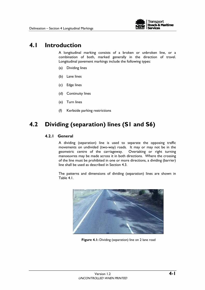
A dividing (separation) line is used to separate the opposing traffic movements on undivided (two-way) roads. It may or may not be in the geometric centre of the carriageway. Overtaking or right turning manoeuvres may be made across it in both directions. Where the crossing of the line must be prohibited in one or more directions, a dividing (barrier) line shall be used as described in Section 4.3. The patterns and dimensions of dividing (separation) lines are shown in Table 4.1.
Figure 4.1: Dividing (separation) line on 2 lane road
UNCONTROLLED WHEN PRINTED
Delineation – Section 4 Longitudinal Markings
4-2 Version 1.2
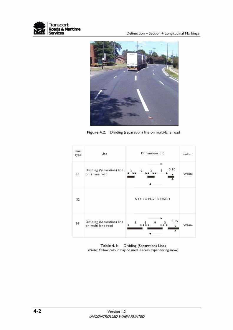
Figure 4.2: Dividing (separation) line on multi-lane road
LineType Use Dimensions (m) Colour
S1Dividing (Separation) lineon 2 lane road White
39 9 0.15
S2
S6 Dividing (Separation) lineon multi lane road
3 9 3 9 0.10
White
N O LO N G E R U SE D
3
Table 4.1: Dividing (Separation) Lines (Note: Yellow colour may be used in areas experiencing snow)
UNCONTROLLED WHEN PRINTED
Delineation – Section 4 Longitudinal Markings
Version 1.2 4-3 UNCONTROLLED WHEN PRINTED
4.2.2 Warrants for use
4.2.2.1 Volume warrants
Dividing line markings, including barrier type (see Section 4.3), where required, should be used on sealed pavements 5.5 m or more wide if the AADT (see Section 1.6 and Section 2.5.3 for AADT definition and further explanation) is in excess of the following:
(a) 300 vehicles on rural roads
(b) 2500 vehicles on urban roads
4.2.2.2 Two-lane two-way roads:
A dividing (separation) line (S1) should be provided on sealed pavements of 5.5 m or more in width, if the road satisfies the volume warrants, outlined in Section 4.2.2.1.
4.2.2.3 Multi-lane roads:
On undivided multi-lane roads where there are more than one lane in one or both directions of traffic, a wider dividing (separation) line (S6) should be provided.
4.2.2.4 Special warrants
Irrespective of the above warrants, marking of other continuous or isolated sections may be desirable where special conditions apply. These conditions include:
(a) Frequent horizontal and/or vertical curves
(b) Sub-standard curves
(c) Areas which are subject to fog
(d) Approaches to a major road
(e) Accident record indicates the need
(f) Continuity of an arterial route
(g) Heavy night traffic or tourist traffic
4.3 Enhanced dividing (separation) lines (S3) Standard dividing (separation) lines should be used on all Roads and Maritime roads. However, in exceptional circumstances, there may be a case when enhanced dividing (separation) line patterns (S3) may sometimes be needed. Refer to Section 5 for the description of enhanced dividing (separation) lines and warrants for their use.
Delineation – Section 4 Longitudinal Markings
4-4 Version 1.2
4.4 Dividing (barrier) lines (BS and BB)
4.4.1 General
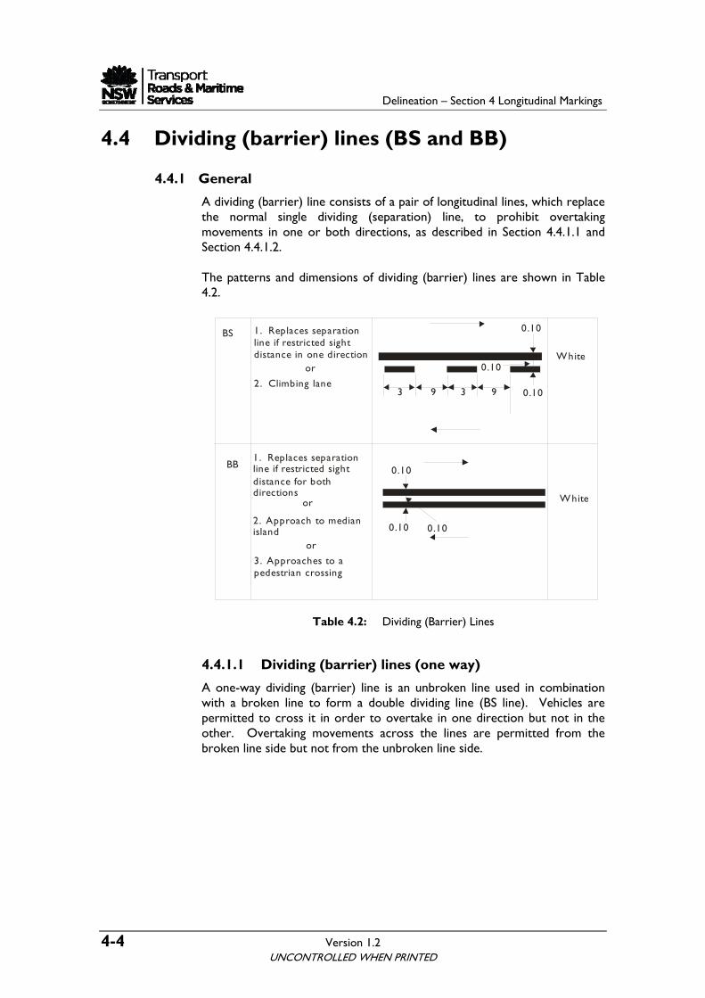
A dividing (barrier) line consists of a pair of longitudinal lines, which replace the normal single dividing (separation) line, to prohibit overtaking movements in one or both directions, as described in Section 4.4.1.1 and Section 4.4.1.2. The patterns and dimensions of dividing (barrier) lines are shown in Table 4.2.
BB1. Replaces separationline if restricted sight distance for bothdirections
or
2. Approach to medianisland 0.100.10
0.10
White
BS 1. Replaces separationline if restricted sightdistance in one direction
or
2. Climbing lane3 9 3 9
0.10
0.10
0.10
White
or
3. Approaches to apedestrian crossing
Table 4.2: Dividing (Barrier) Lines
4.4.1.1 Dividing (barrier) lines (one way)
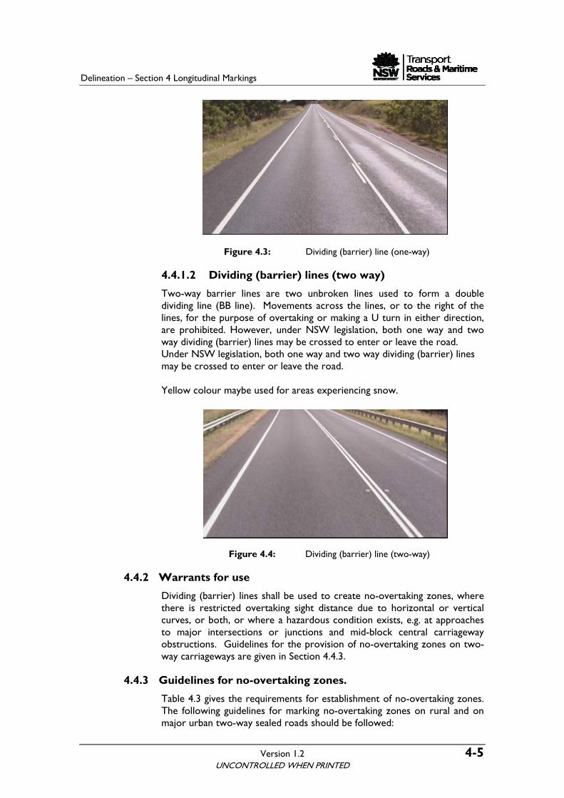
A one-way dividing (barrier) line is an unbroken line used in combination with a broken line to form a double dividing line (BS line). Vehicles are permitted to cross it in order to overtake in one direction but not in the other. Overtaking movements across the lines are permitted from the broken line side but not from the unbroken line side.
UNCONTROLLED WHEN PRINTED
Delineation – Section 4 Longitudinal Markings
Version 1.2 4-5
Figure 4.3: Dividing (barrier) line (one-way)
4.4.1.2 Dividing (barrier) lines (two way)
Two-way barrier lines are two unbroken lines used to form a double dividing line (BB line). Movements across the lines, or to the right of the lines, for the purpose of overtaking or making a U turn in either direction, are prohibited. However, under NSW legislation, both one way and two way dividing (barrier) lines may be crossed to enter or leave the road. Under NSW legislation, both one way and two way dividing (barrier) lines may be crossed to enter or leave the road. Yellow colour maybe used for areas experiencing snow.
Figure 4.4: Dividing (barrier) line (two-way)
4.4.2 Warrants for use
Dividing (barrier) lines shall be used to create no-overtaking zones, where there is restricted overtaking sight distance due to horizontal or vertical curves, or both, or where a hazardous condition exists, e.g. at approaches to major intersections or junctions and mid-block central carriageway obstructions. Guidelines for the provision of no-overtaking zones on two-way carriageways are given in Section 4.4.3.
4.4.3 Guidelines for no-overtaking zones.
Table 4.3 gives the requirements for establishment of no-overtaking zones. The following guidelines for marking no-overtaking zones on rural and on major urban two-way sealed roads should be followed:
UNCONTROLLED WHEN PRINTED
Delineation – Section 4 Longitudinal Markings
4-6 Version 1.2 UNCONTROLLED WHEN PRINTED
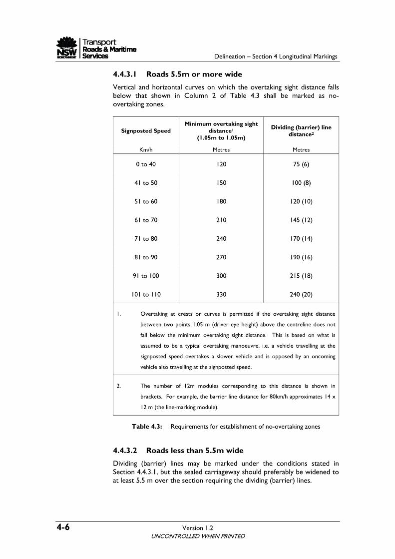
4.4.3.1 Roads 5.5m or more wide
Vertical and horizontal curves on which the overtaking sight distance falls below that shown in Column 2 of Table 4.3 shall be marked as no-overtaking zones.
Signposted Speed Minimum overtaking sight
distance1
(1.05m to 1.05m)
Dividing (barrier) line distance2
Km/h Metres Metres
0 to 40 120 75 (6)
41 to 50 150 100 (8)
51 to 60 180 120 (10)
61 to 70 210 145 (12)
71 to 80 240 170 (14)
81 to 90 270 190 (16)
91 to 100 300 215 (18)
101 to 110 330 240 (20)
1. Overtaking at crests or curves is permitted if the overtaking sight distance
between two points 1.05 m (driver eye height) above the centreline does not
fall below the minimum overtaking sight distance. This is based on what is
assumed to be a typical overtaking manoeuvre, i.e. a vehicle travelling at the
signposted speed overtakes a slower vehicle and is opposed by an oncoming
vehicle also travelling at the signposted speed.
2. The number of 12m modules corresponding to this distance is shown in
brackets. For example, the barrier line distance for 80km/h approximates 14 x
12 m (the line-marking module).
Table 4.3: Requirements for establishment of no-overtaking zones
4.4.3.2 Roads less than 5.5m wide
Dividing (barrier) lines may be marked under the conditions stated in Section 4.4.3.1, but the sealed carriageway should preferably be widened to at least 5.5 m over the section requiring the dividing (barrier) lines.
Delineation – Section 4 Longitudinal Markings
Version 1.2 4-7
4.4.3.3 Two-lane bridges
Dividing (barrier) lines shall not normally be marked on two-lane bridges, unless the warrant in Section 4.4.3.1 indicates that a no-overtaking zone is required and the width is 5.5 m or greater between kerbs. When linemarking is not possible regulatory signs would be used.
4.4.4 Location and setting out
The method for locating and setting out dividing (barrier) lines is given in Appendix A.
4.5 Enhanced dividing (barrier) lines (BS1, BB1, and BB2)
Standard dividing (barrier) lines should be used on all Roads and Maritime roads. However, in exceptional circumstances, there may be a case when enhanced dividing (barrier) line patterns (BS1, BB1, and BB2 ) may sometimes be needed. Refer to Section 5 for the description of enhanced dividing (barrier) lines and guidelines for their use.
4.6 Lane lines (L1, L2, L3, L4, L5, L6 and L7)
4.6.1 General
A lane line shall be used to separate traffic moving in the same direction. The patterns and dimensions of lane lines are shown in Table 4.4.
4.6.2 Warrants for use
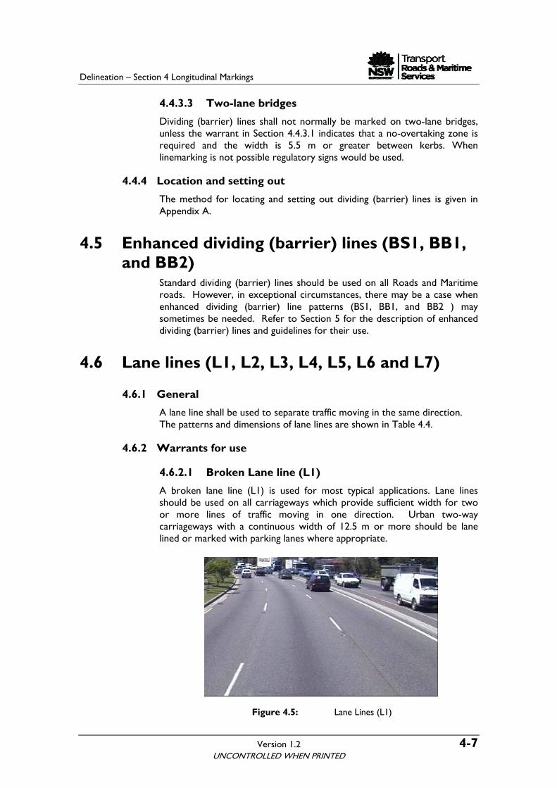
4.6.2.1 Broken Lane line (L1)
A broken lane line (L1) is used for most typical applications. Lane lines should be used on all carriageways which provide sufficient width for two or more lines of traffic moving in one direction. Urban two-way carriageways with a continuous width of 12.5 m or more should be lane lined or marked with parking lanes where appropriate.
Figure 4.5: Lane Lines (L1)
UNCONTROLLED WHEN PRINTED

Delineation – Section 4 Longitudinal Markings
4-8 Version 1.2
L1 Lane line on multi
Whitelane roads including motorways and dual-carriageways
3 9 3 9 0.10
LineType Use Dimensions (m) Colour
Lane line(Approval needed of GM TrafficManagement)
WhiteL50.200
3 1 35 5
0 .1 0
Defines the edge of a Bus Lane and Bus Only laneadjacent to generaltraffic lane
L6 White
L7
Defines the edge of aBicycle lane adjacent to generaltraffic lane
0.10White
L4 Exit lane line on
Lane line on
White
WhiteL3
multilane roundabouts
multi lane road
0.10
9 3 9 3 0.10
L2
Lane line(profile) onmotorways,dual carriagewaysor on special locationssuch as bridges (Approval neededof GM, Traffic Management)
White
3 9 3 9 0.10
Table 4.4: Lane Lines
UNCONTROLLED WHEN PRINTED
Delineation – Section 4 Longitudinal Markings
Version 1.2 4-9
4.6.2.2 Enhanced (Profile) Lane line (L2)
Enhanced lane line (L2), similar to L1 in pattern and dimensions but profiled, may be used on motorways, dual carriageways; or special locations such as bridges and tunnels. It has the same dimensions as L1 line, except that it is profiled. Earlier a broken simulated line (using non-reflective raised pavement markers) was used as an L2 lane line. Roads and Maritime has discontinued its use. Noise impact must be taken into account when considering the use of profile linemarking. Refer to Section 5.2.6 for specifications, drawings, warrants and applications of these markings.
Figure 4.6: Lane Lines (L2)
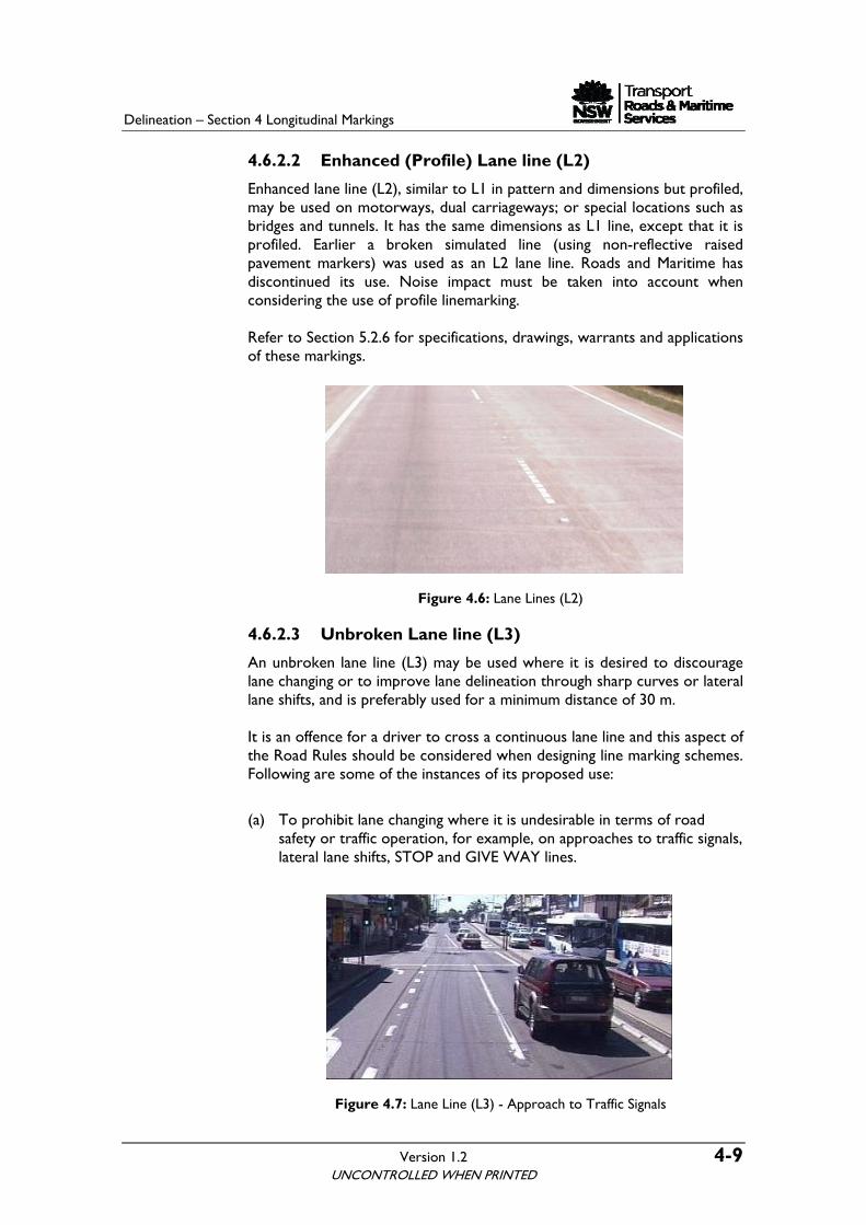
4.6.2.3 Unbroken Lane line (L3)
An unbroken lane line (L3) may be used where it is desired to discourage lane changing or to improve lane delineation through sharp curves or lateral lane shifts, and is preferably used for a minimum distance of 30 m. It is an offence for a driver to cross a continuous lane line and this aspect of the Road Rules should be considered when designing line marking schemes. Following are some of the instances of its proposed use:
(a) To prohibit lane changing where it is undesirable in terms of road safety or traffic operation, for example, on approaches to traffic signals, lateral lane shifts, STOP and GIVE WAY lines.
Figure 4.7: Lane Line (L3) - Approach to Traffic Signals
UNCONTROLLED WHEN PRINTED
Delineation – Section 4 Longitudinal Markings
4-10 Version 1.2
(b) Where it is desired to discourage lane changing while improving the lane delineation, for example, through sharp curves, over crests or through the changes in the alignments of lanes.
Figure 4.8: Lane Line (L3) - Lateral lane shift
(c) Between a through lane and an acceleration lane, deceleration lane or turning lane. A continuity line is used across the lead-in tapers.
Figure 4.9: Lane Lines (L3) - Discourage lane changing
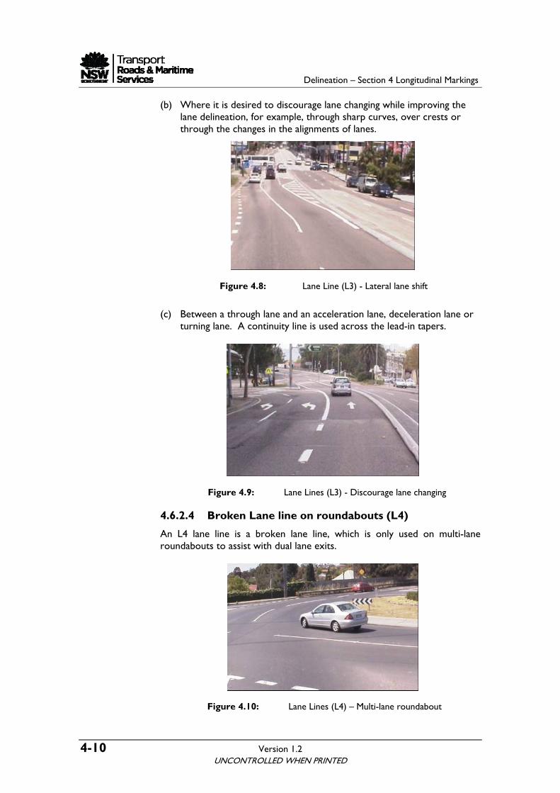
4.6.2.4 Broken Lane line on roundabouts (L4)
An L4 lane line is a broken lane line, which is only used on multi-lane roundabouts to assist with dual lane exits.
Figure 4.10: Lane Lines (L4) – Multi-lane roundabout
UNCONTROLLED WHEN PRINTED
Delineation – Section 4 Longitudinal Markings
Version 1.2 4-11
4.6.2.5 Enhanced unbroken Lane line (L5)
Refer to Section 5.5 for the description of enhanced unbroken lane line (L5), specifications, drawings, warrants and applications.
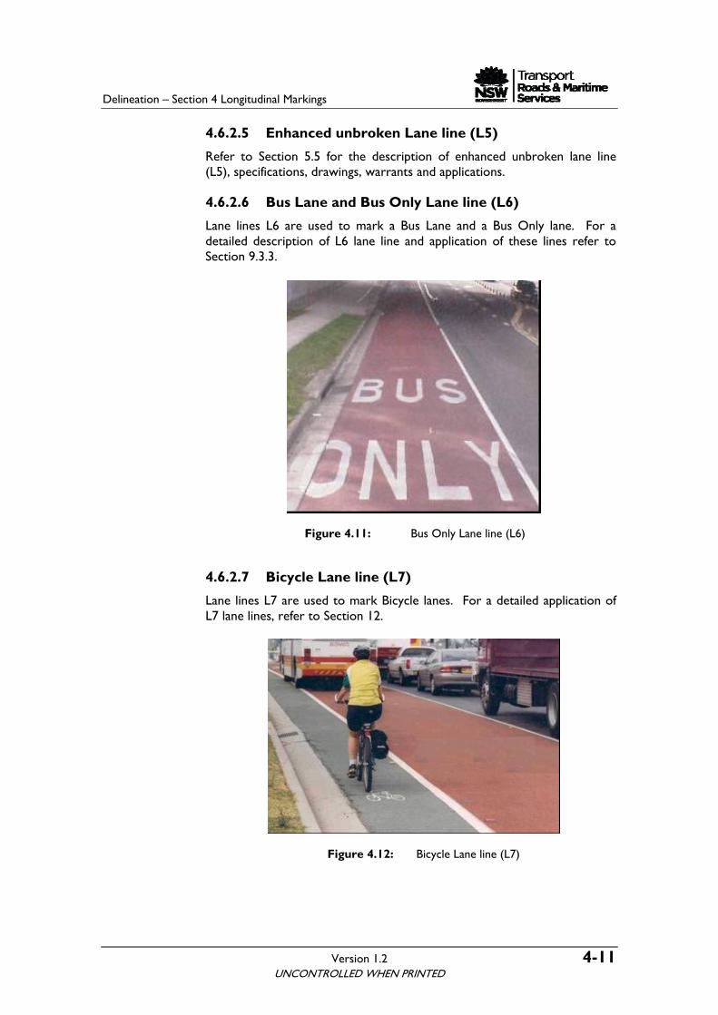
4.6.2.6 Bus Lane and Bus Only Lane line (L6)
Lane lines L6 are used to mark a Bus Lane and a Bus Only lane. For a detailed description of L6 lane line and application of these lines refer to Section 9.3.3.
Figure 4.11: Bus Only Lane line (L6)
4.6.2.7 Bicycle Lane line (L7)
Lane lines L7 are used to mark Bicycle lanes. For a detailed application of L7 lane lines, refer to Section 12.
Figure 4.12: Bicycle Lane line (L7)
UNCONTROLLED WHEN PRINTED
Delineation – Section 4 Longitudinal Markings
4-12 Version 1.2
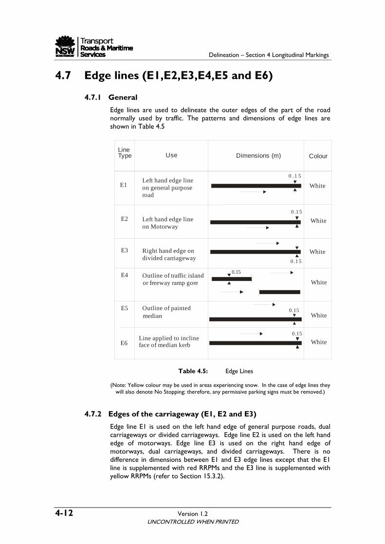
4.7 Edge lines (E1,E2,E3,E4,E5 and E6)
4.7.1 General
Edge lines are used to delineate the outer edges of the part of the road normally used by traffic. The patterns and dimensions of edge lines are shown in Table 4.5
LineType Use Dimensions (m) Colour
E1Left hand edge lineon general purposeroad
Right hand edge ondivided carriageway
Left hand edge lineon Motorway
Outline of painted
Outline of traffic island
White
White
White
White
White
E3
E2
E5
E4
median
or freeway ramp gore
0.15
0 .1 5
0 .1 5
0 .1 5
0.15
E6Line applied to incline face of median kerb
0.15
White
Table 4.5: Edge Lines
(Note: Yellow colour may be used in areas experiencing snow. In the case of edge lines they will also denote No Stopping; therefore, any permissive parking signs must be removed.)
4.7.2 Edges of the carriageway (E1, E2 and E3)
Edge line E1 is used on the left hand edge of general purpose roads, dual carriageways or divided carriageways. Edge line E2 is used on the left hand edge of motorways. Edge line E3 is used on the right hand edge of motorways, dual carriageways, and divided carriageways. There is no difference in dimensions between E1 and E3 edge lines except that the E1 line is supplemented with red RRPMs and the E3 line is supplemented with yellow RRPMs (refer to Section 15.3.2).
UNCONTROLLED WHEN PRINTED
Delineation – Section 4 Longitudinal Markings
Version 1.2 4-13
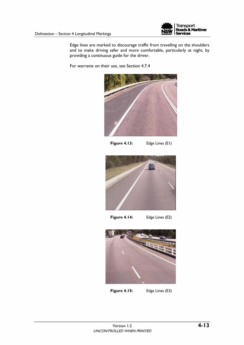
Edge lines are marked to discourage traffic from travelling on the shoulders and to make driving safer and more comfortable, particularly at night, by providing a continuous guide for the driver. For warrants on their use, see Section 4.7.4
Figure 4.13: Edge Lines (E1)
Figure 4.14: Edge Lines (E2)
Figure 4.15: Edge Lines (E3)
UNCONTROLLED WHEN PRINTED
Delineation – Section 4 Longitudinal Markings
4-14 Version 1.2
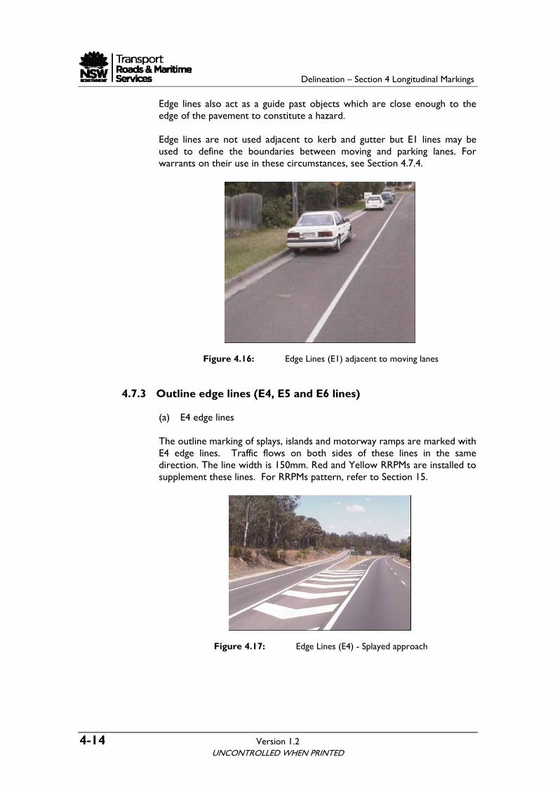
Edge lines also act as a guide past objects which are close enough to the edge of the pavement to constitute a hazard. Edge lines are not used adjacent to kerb and gutter but E1 lines may be used to define the boundaries between moving and parking lanes. For warrants on their use in these circumstances, see Section 4.7.4.
Figure 4.16: Edge Lines (E1) adjacent to moving lanes
4.7.3 Outline edge lines (E4, E5 and E6 lines)
(a) E4 edge lines The outline marking of splays, islands and motorway ramps are marked with E4 edge lines. Traffic flows on both sides of these lines in the same direction. The line width is 150mm. Red and Yellow RRPMs are installed to supplement these lines. For RRPMs pattern, refer to Section 15.
Figure 4.17: Edge Lines (E4) - Splayed approach
UNCONTROLLED WHEN PRINTED
Delineation – Section 4 Longitudinal Markings
Version 1.2 4-15
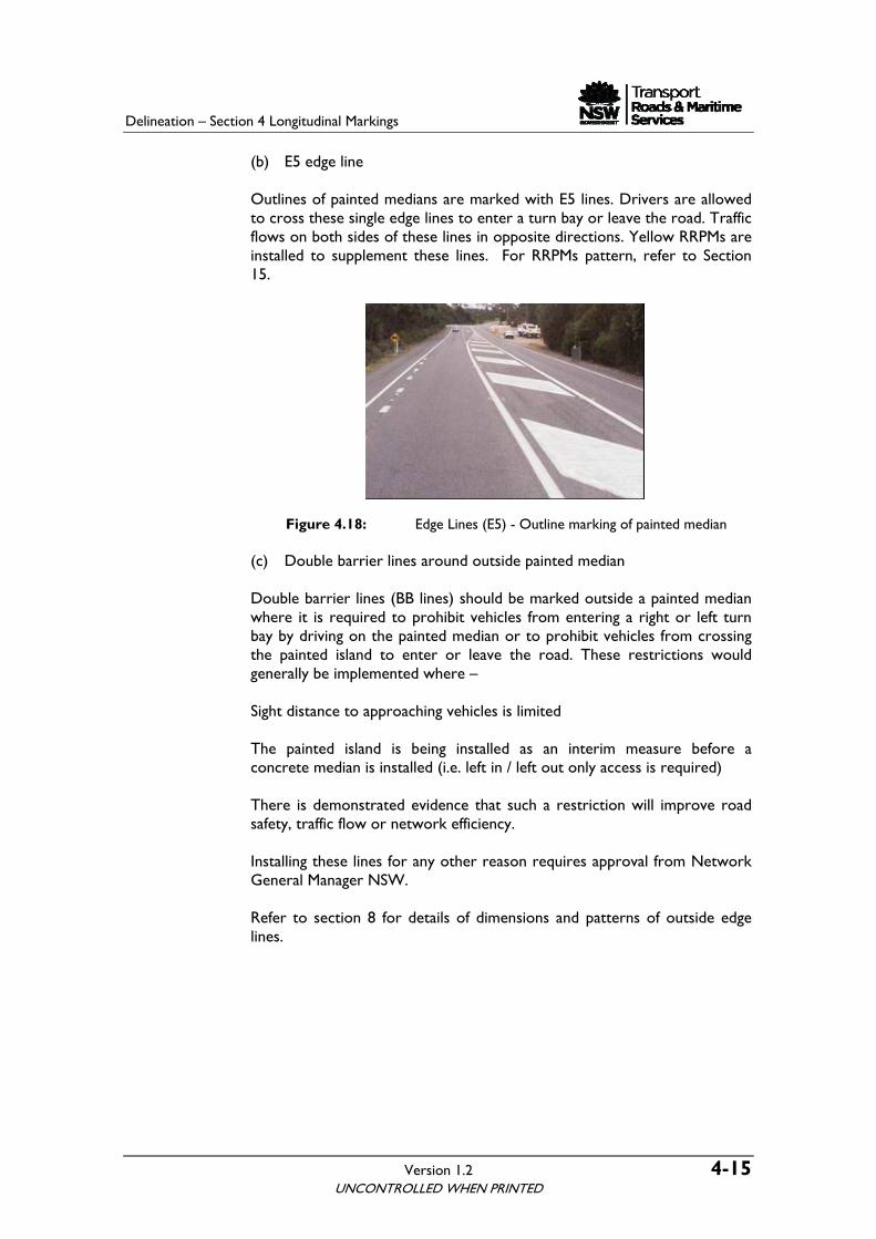
(b) E5 edge line Outlines of painted medians are marked with E5 lines. Drivers are allowed to cross these single edge lines to enter a turn bay or leave the road. Traffic flows on both sides of these lines in opposite directions. Yellow RRPMs are installed to supplement these lines. For RRPMs pattern, refer to Section 15.
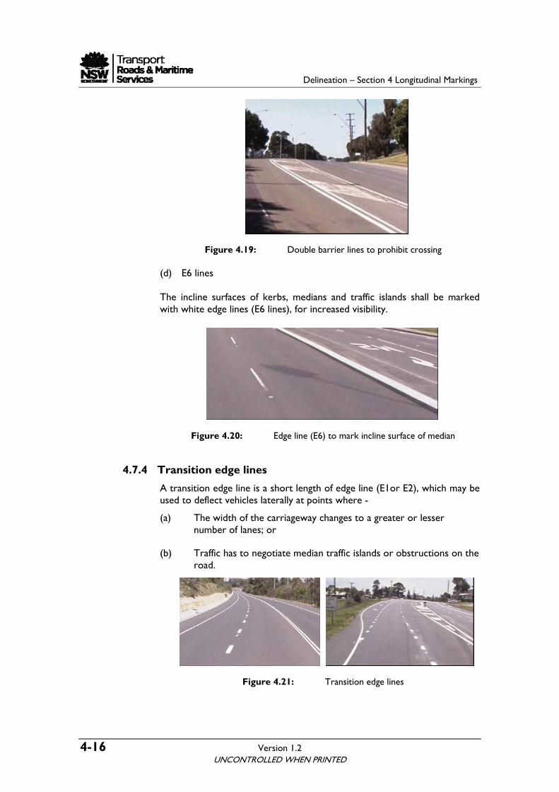
Figure 4.18: Edge Lines (E5) - Outline marking of painted median (c) Double barrier lines around outside painted median Double barrier lines (BB lines) should be marked outside a painted median where it is required to prohibit vehicles from entering a right or left turn bay by driving on the painted median or to prohibit vehicles from crossing the painted island to enter or leave the road. These restrictions would generally be implemented where – Sight distance to approaching vehicles is limited The painted island is being installed as an interim measure before a concrete median is installed (i.e. left in / left out only access is required) There is demonstrated evidence that such a restriction will improve road safety, traffic flow or network efficiency. Installing these lines for any other reason requires approval from Network General Manager NSW. Refer to section 8 for details of dimensions and patterns of outside edge lines.
UNCONTROLLED WHEN PRINTED
Delineation – Section 4 Longitudinal Markings
4-16 Version 1.2
Figure 4.19: Double barrier lines to prohibit crossing (d) E6 lines The incline surfaces of kerbs, medians and traffic islands shall be marked with white edge lines (E6 lines), for increased visibility.
Figure 4.20: Edge line (E6) to mark incline surface of median
4.7.4 Transition edge lines
A transition edge line is a short length of edge line (E1or E2), which may be used to deflect vehicles laterally at points where -
(a) The width of the carriageway changes to a greater or lesser number of lanes; or
(b) Traffic has to negotiate median traffic islands or obstructions on the road.
Figure 4.21: Transition edge lines
UNCONTROLLED WHEN PRINTED
Delineation – Section 4 Longitudinal Markings
Version 1.2 4-17 UNCONTROLLED WHEN PRINTED
The required length of the transition line shall be determined by the following equations: L = V for diverging or minor changes L= 1.6 V for merging areas Where L = length of transition, in metres V = signposted speed, in kilometres per hour Where traffic volumes are high, longer transitions may be required for merging.
4.7.5 Warrants for edge lines
On a carriageway of more than one lane, edge lines shall not be used unless a dividing line exists and the pavement is at least 6.8 m in width, or unless special circumstances exist, i.e. poor alignment, fog and similar conditions. Where edge lines are used, they shall be placed on both sides of the sealed surface, in accordance with the following:
4.7.5.1 Volume warrants
Edge line markings should be used on the sealed pavements 6.8m or more wide if the AADT is in excess of the following:
(a) 750 vehicles on rural roads
(b) 4,000 vehicles on urban road
4.7.5.2 Undivided roads:
An E1 edge line is used on both edges of sealed pavements of 6.8 m or more in width if a dividing line/lane lines exist.
4.7.5.3 Dual carriageways or divided carriageway:
An E1 edge line is used on the left edge and an E3 edge line on the right edge.
4.7.5.4 Motorways
An E2 edge line is used on the left edge and an E3 edge line on the right edge of all freeways and ramps.
4.7.5.5 Special warrants
Irrespective of the above warrants, marking of either continuous or isolated sections of edge line may be desirable where special conditions apply. These conditions include:
(a) Frequent horizontal and/or vertical curves
Delineation – Section 4 Longitudinal Markings
4-18 Version 1.2
(b) Sub-standard curves
(c) Areas which are subject to fog
(d) Approaches to an edgelined road
(e) Accident record indicates the need
(f) Continuity of an arterial route
(g) Heavy night traffic or tourist traffic
4.7.6 Profile edge lines
Profile edge line marking is mainly recommended for use on freeways or motorways to separate the edge of the sealed shoulder from the main carriageway. Noise impact must be taken into account when considering the use of profile linemarking. Refer to Section 5.2.6 for specifications, drawings, warrants and applications of these markings
4.8 Continuity lines
4.8.1 General
Continuity lines are used to alert the motorists to the forthcoming change in the nature of the lane they are travelling or in the adjoining lane. It defines the edge of the through carriageway. The patterns and dimensions of continuity lines are shown in Table 4.6.
LineType Use Dimensions (m) Colour
C 1 3 33 31 1 1 1 0 .1 51W hite
Defines edge of through carriageway lane
Table 4.6: Continuity Lines
4.8.2 Applications
A continuity line (C1 line) must be used:
(a) To indicate the separation of a portion of a carriageway that is assigned for through traffic, from that for exclusive turning traffic.
UNCONTROLLED WHEN PRINTED
Delineation – Section 4 Longitudinal Markings
Version 1.2 4-19
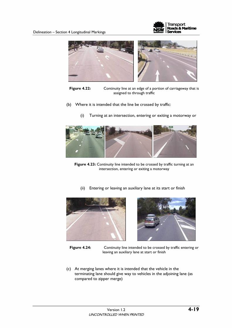
Figure 4.22: Continuity line at an edge of a portion of carriageway that is assigned to through traffic
(b) Where it is intended that the line be crossed by traffic:
(i) Turning at an intersection, entering or exiting a motorway or
Figure 4.23: Continuity line intended to be crossed by traffic turning at an intersection, entering or exiting a motorway
(ii) Entering or leaving an auxiliary lane at its start or finish
Figure 4.24: Continuity line intended to be crossed by traffic entering or leaving an auxiliary lane at start or finish
(c) At merging lanes where it is intended that the vehicle in the terminating lane should give way to vehicles in the adjoining lane (as compared to zipper merge)
UNCONTROLLED WHEN PRINTED
Delineation – Section 4 Longitudinal Markings
4-20 Version 1.2
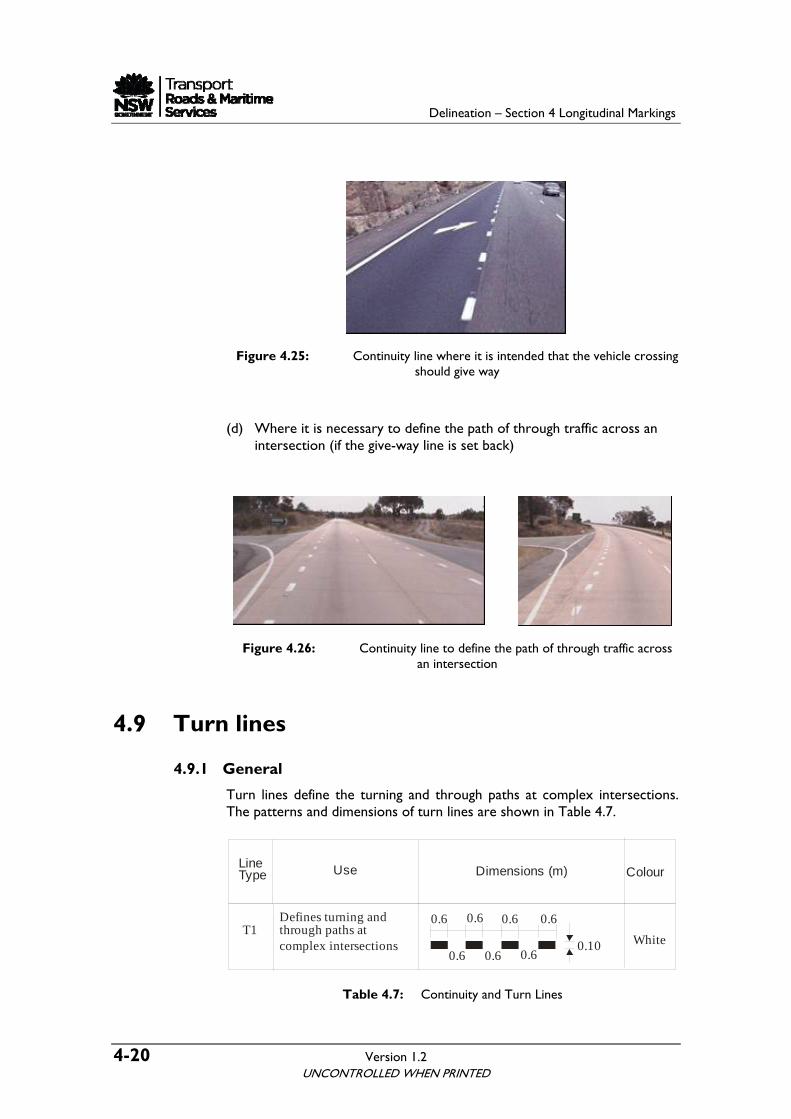
Figure 4.25: Continuity line where it is intended that the vehicle crossing should give way
(d) Where it is necessary to define the path of through traffic across an intersection (if the give-way line is set back)
Figure 4.26: Continuity line to define the path of through traffic across an intersection
4.9 Turn lines
4.9.1 General
Turn lines define the turning and through paths at complex intersections. The patterns and dimensions of turn lines are shown in Table 4.7.
T1
0.6
0.6
0.10 White
Defines turning and through paths at complex intersections
0.6
0.6 0.6 0.6
0.6
LineType Use Dimensions (m) Colour
Table 4.7: Continuity and Turn Lines
UNCONTROLLED WHEN PRINTED
Delineation – Section 4 Longitudinal Markings
Version 1.2 4-21
4.9.2 Applications
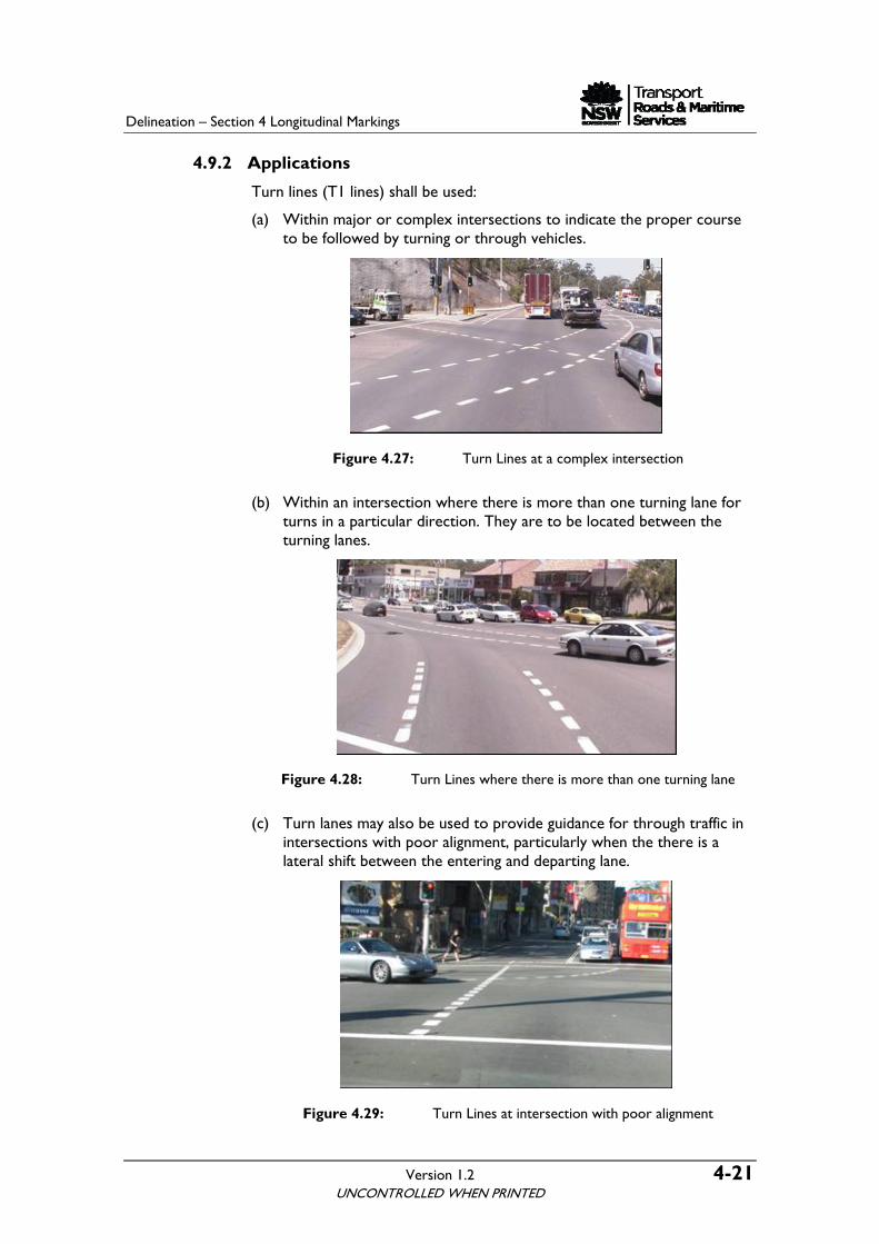
Turn lines (T1 lines) shall be used:
(a) Within major or complex intersections to indicate the proper course to be followed by turning or through vehicles.
Figure 4.27: Turn Lines at a complex intersection
(b) Within an intersection where there is more than one turning lane for turns in a particular direction. They are to be located between the turning lanes.
Figure 4.28: Turn Lines where there is more than one turning lane
(c) Turn lanes may also be used to provide guidance for through traffic in intersections with poor alignment, particularly when the there is a lateral shift between the entering and departing lane.
Figure 4.29: Turn Lines at intersection with poor alignment
UNCONTROLLED WHEN PRINTED
Delineation – Section 4 Longitudinal Markings
4-22 Version 1.2
They shall not be used when the path to be followed is obvious to drivers under all conditions, unless there is crash history related to vehicles driving off line through an intersection.
4.10 Longitudinal markings for bicycle facilities Longitudinal lines for bicycle facilities are given in Table 4.8. For application of these lines refer to Section 12.
S5Bicycle lane separation linefor off-raod bike path(Straight sections)
Bicycle lane continuity line
Bicycle separation linefor off-road bike path(with restricted visibility)
White
C4
S4
0.10
L7 Bicycle lane line
White
0.10
3 33 31 1 1 1 0 .1 01
White
White3 33 31 1 1 1 0 .1 01
E7 Bicycle edge linefor off-road bikepaths & shred paths
0.10White
Table 4.8: Longitudinal Lines for Bicycle Facilities
4.11 Pavement markings for kerbside parking restrictions
Refer to Section 13 for Pavement marking for kerbside parking restrictions. The section contains specifications, drawings, warrants and applications of these markings
UNCONTROLLED WHEN PRINTED
Delineation – Section 4 Longitudinal Markings
Version 1.2 4-23
4.12 Pavement markings for Bus lanes and Bus Only lanes
Refer to Section 9 for Pavement markings for Bus lanes and Bus Only lanes. The section contains specifications, drawings, warrants and applications of these markings
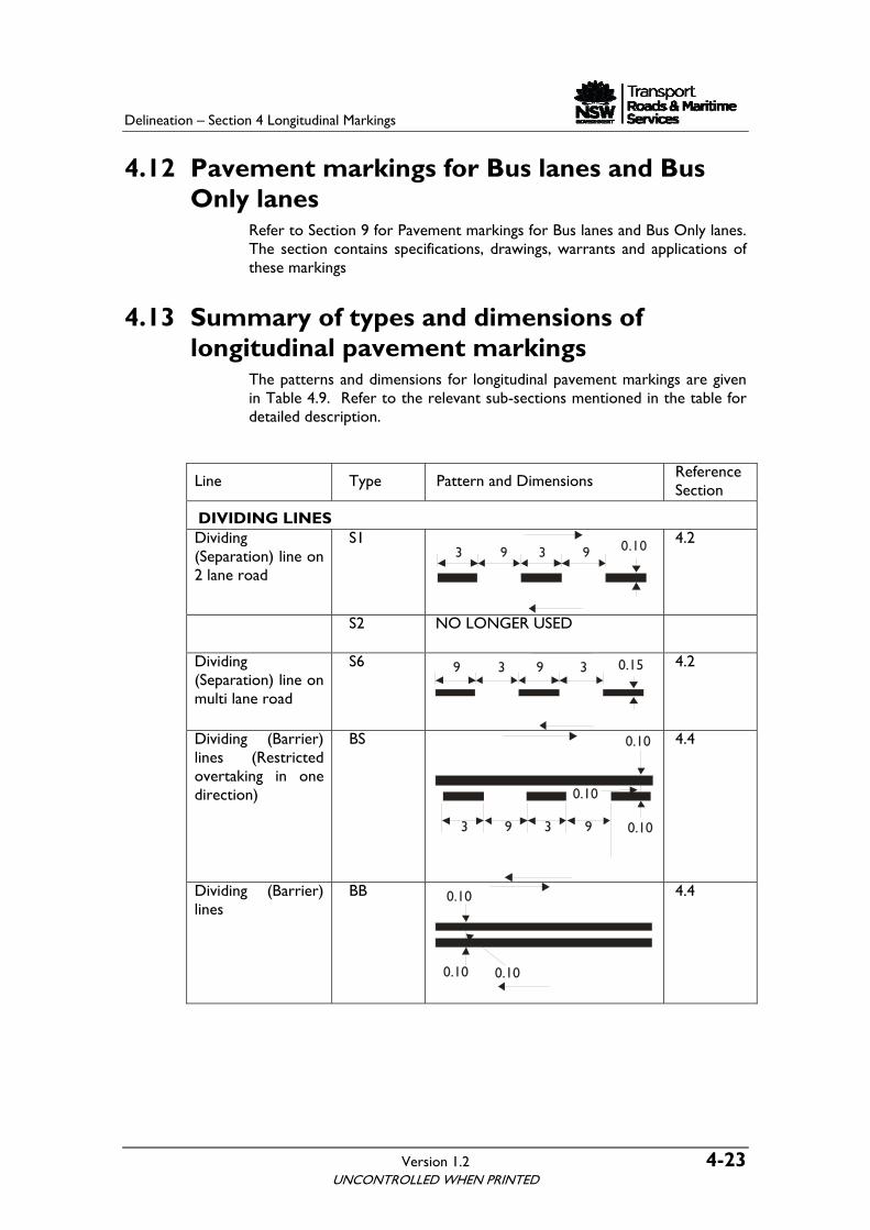
4.13 Summary of types and dimensions of longitudinal pavement markings
The patterns and dimensions for longitudinal pavement markings are given in Table 4.9. Refer to the relevant sub-sections mentioned in the table for detailed description.
Line Type Pattern and Dimensions Reference Section
DIVIDING LINES Dividing (Separation) line on 2 lane road
S1 3 9 3 9 0.10
4.2
S2 NO LONGER USED
Dividing (Separation) line on multi lane road
S6
4.2 9 3 9 3 0.15
Dividing (Barrier) lines (Restricted overtaking in one direction)
BS
4.4
Dividing (Barrier) lines
BB
4.4
UNCONTROLLED WHEN PRINTED
0.100.10
0.10
3 9 3 9
0.10
0.10
0.10
Delineation – Section 4 Longitudinal Markings
4-24 Version 1.2 UNCONTROLLED WHEN PRINTED
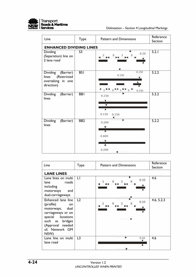
Line Type Pattern and Dimensions Reference Section
ENHANCED DIVIDING LINES 5.2.1 Dividing S3
(Separatio2 lane road
n) line on 0.209393
Dividing (Barrier) BS1 lines (Restricted overtaking in one direction)
0.150
0.1500.150
9393
5.2.2
Dividing (Barrier) BB1 5.2.2 lines
0.150
0.150
0.150
Dividing (Barrier) BB2 5.2.2 lines
0.600
0.200
0.200
Line Type Pattern and Dimensions Reference
Section
LANE LINES Lane lines on multi
s and
L1 4.6 lane roads including motorwaydual-carriageways Enhanced lane line L2 4.6, 5.2.3 (profile) on motorways, dual carriageways or on special locations such as bridges (Approval needed of, Network GM NSW)
Lane line on multi lane road
L3
4.6 0.10
3 9 3 9 0.10
3 9 3 9 0.10
Delineation – Section 4 Longitudinal Markings
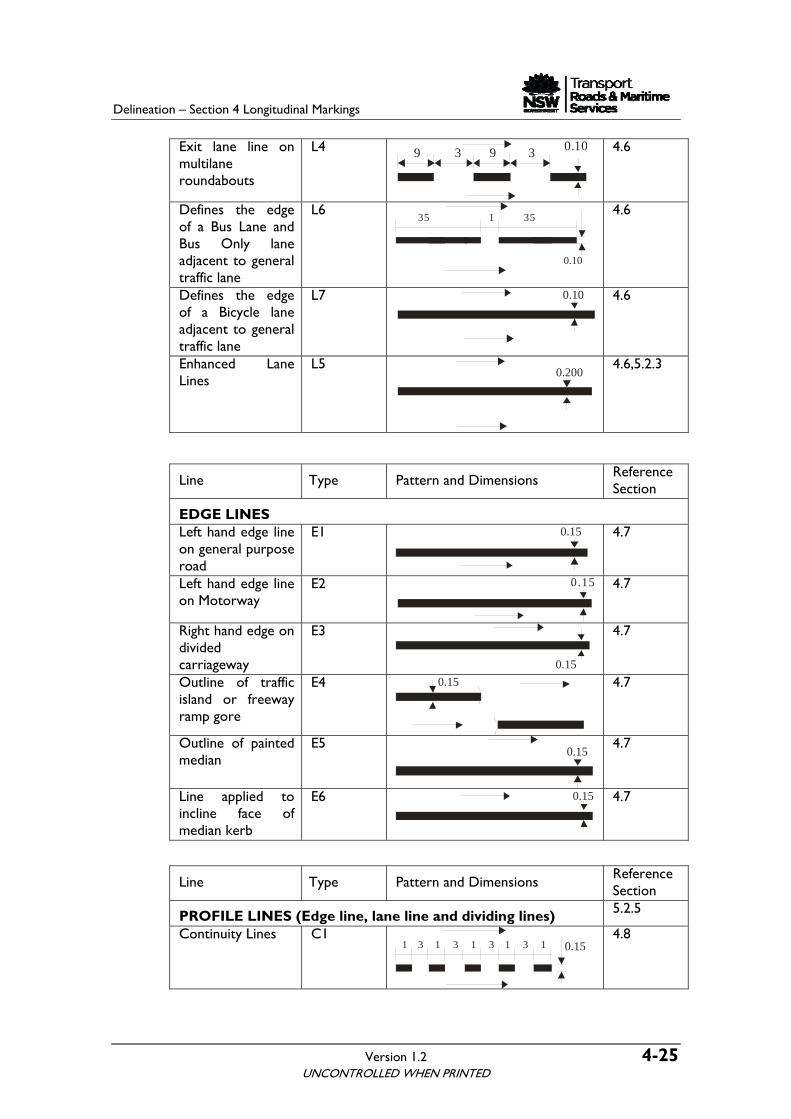
Version 1.2 4-25 UNCONTROLLED WHEN PRINTED
roundabouts
Exit lane line on multilane
L4 9 3 9 3 0.10
4.6
Defines the edge of a Bus LanBus Only
e and lane
adjacent to general traffic lane
L6
4.6
Defines the edge of a Bicycle lane adjacent to general
L
traffic lane
7 0.10
4.6
Enhanced Lane Lines
L5 0.200
4.6,5.2.3
Line Type Pattern and Dimensions Reference Section
EDGE LINES Left hand edge line on general purpose
road
E1 4.7
Left hand edge line on Motorway
E2 0.15
4.7
Right hand edge on divided carriageway
E3
4.7
Outline of traffic island or freeway ramp gore
E4
4.7
Outline of painted median
E5
4.7
Line applied to incline face of median kerb
E6
4.7
Line Type Reference Section
Pattern and Dimensions
PROFILE LINES (Edge line, lane line and dividing lines) .2.5 5
Continuity Lines C1
4.8
0.15
3 33 31 1 1 11 0.15
0.15
0.15
0.15
0.15
3 1 35 5
0.10
Delineation – Section 4 Longitudinal Markings
4-26 Version 1.2 UNCONTROLLED WHEN PRINTED
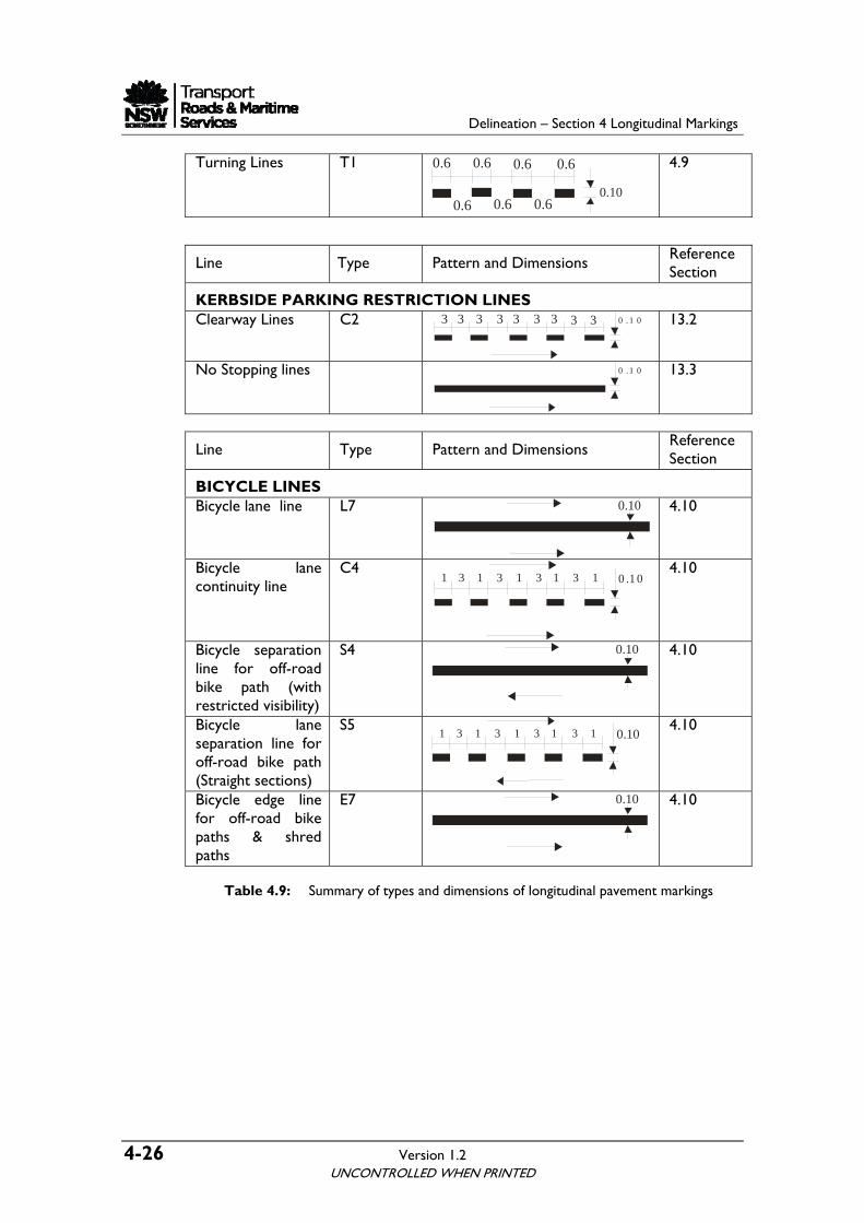
Turning Lines T1 4.9
Line Type Reference Section Pattern and Dimensions
KERBSIDE PARKING RESTRICTION LINES Clearway Lines C2 3 0 .1 033 3 33 33 3
13.2
No Stopping lines 0 .1 0
13.3
Type Pattern and Dimensions ence Section Line Refer
BICYCLE LINES Bicycle lane line L7 0.10
4.10
Bicycle lane continuity line
C4 3 33 31 1 1 1 0 .1 01
4.10
Bicycle separation line for off-road bike path (with restricted visibility)
S4 4.10
Bicycle lane separation line for off-road bike path (Straight sections)
S5
4.10
Bicycle edge line for off-road bike paths & shred paths
E7
4.10
Table 4.9: Summ
ary of types and dimensions of longitudinal pavement markings
0.10
3 33 31 1 1 1 0.10 1
0.10
0.6
0.6
0.10 0.6
0.6 0.6 0.6
0.6

For further enquiries www.rta.nsw.gov.au 13 22 13
Roads and Traffic Authority March 2008 RTA/Pub. 08.091