
Delft University of Technology Structural analysis for shallow...
13
Delft University of Technology Structural analysis for shallow tunnels in soft soils Vu Minh, N.; Broere, Wout; Bosch, Johan W. DOI 10.1061/(ASCE)GM.1943-5622.0000866 Publication date 2017 Document Version Final published version Published in International Journal of Geomechanics Citation (APA) Vu Minh, N., Broere, W., & Bosch, J. W. (2017). Structural analysis for shallow tunnels in soft soils. International Journal of Geomechanics, 17(8), [04017038]. https://doi.org/10.1061/(ASCE)GM.1943- 5622.0000866 Important note To cite this publication, please use the final published version (if applicable). Please check the document version above. Copyright Other than for strictly personal use, it is not permitted to download, forward or distribute the text or part of it, without the consent of the author(s) and/or copyright holder(s), unless the work is under an open content license such as Creative Commons. Takedown policy Please contact us and provide details if you believe this document breaches copyrights. We will remove access to the work immediately and investigate your claim. This work is downloaded from Delft University of Technology. For technical reasons the number of authors shown on this cover page is limited to a maximum of 10.
Transcript of Delft University of Technology Structural analysis for shallow...
Delft University of Technology
Structural analysis for shallow tunnels in soft soils
Vu Minh, N.; Broere, Wout; Bosch, Johan W.
DOI10.1061/(ASCE)GM.1943-5622.0000866Publication date2017Document VersionFinal published versionPublished inInternational Journal of Geomechanics
Citation (APA)Vu Minh, N., Broere, W., & Bosch, J. W. (2017). Structural analysis for shallow tunnels in soft soils.International Journal of Geomechanics, 17(8), [04017038]. https://doi.org/10.1061/(ASCE)GM.1943-5622.0000866
Important noteTo cite this publication, please use the final published version (if applicable).Please check the document version above.
CopyrightOther than for strictly personal use, it is not permitted to download, forward or distribute the text or part of it, without the consentof the author(s) and/or copyright holder(s), unless the work is under an open content license such as Creative Commons.
Takedown policyPlease contact us and provide details if you believe this document breaches copyrights.We will remove access to the work immediately and investigate your claim.
This work is downloaded from Delft University of Technology.For technical reasons the number of authors shown on this cover page is limited to a maximum of 10.

Structural Analysis for Shallow Tunnels in Soft SoilsMinh Ngan Vu1; Wout Broere2; and JohanW. Bosch3
Abstract: Generally, studies on structural design for bored tunnels focus on moderate to deep tunnels (cover-to-diameter ratio C/D ≥ 2).Such tunnel design methods cannot be used for shallow-situated bored tunnels because the influence of buoyancy is discounted, and actualloads on the tunnel lining are not taken into account properly. This paper proposes a new model that has more accurate loads on the tunnel lin-ing combined with finite-element analysis for shallow tunnels. Internal forces and deformations of various shallow bored tunnels are investi-gated. The relationship between the optimal thickness-to-diameter ratio d/D of the tunnel cross section and the cover-to-diameter ratio C/D isalso studied. DOI: 10.1061/(ASCE)GM.1943-5622.0000866. This work is made available under the terms of the Creative CommonsAttribution 4.0 International license, http://creativecommons.org/licenses/by/4.0/.
Author keywords: Cover-to-diameter ratio; Tunnel lining; Shallow bored tunnel; Soft soil.
Introduction
Tunnel boring machines are widely used in the construction ofunderground infrastructures in urban areas because disturbances atthe surface level can be reduced significantly during the construc-tion and because of their ability to limit settlements and damage toexisting buildings. In an environment with soft overburden, particu-larly in soft Holocene layers, buildings are generally built on pilefoundations. The tunnel is often designed well below the pile tiplevel. This is done for two reasons: to decrease interaction betweenthe tunneling process and the piles, and to avoid having to drivethrough old abandoned piles that are still present below the streets.This results in relatively deep track tunnels and in deep stationboxes. If the tunnels could be located at more shallow levels, suchthat they are located above the pile toe level, then the impact of tun-neling-induced soil displacements would be largely eliminated.Such a reduction of the tunnel depth would also reduce the requireddepth of the station boxes and the construction costs. Other advan-tages are the low operational expenditure in the long-term and theshorter traveling time between the surface and the platforms.
Taking into account these conditions, this paper takes a look atthe structural design of tunnel linings for shallow tunnels in softsoils. Many calculation models have been proposed and developedsince 1926 for tunnel design. Schmid (1926) proposed the first anal-ysis method for an elastic continuum. Schulze and Duddeck (1964)presented a bedded ring model for shallow tunnels with limitedcover. Morgan (1961) proposed an analytical solution using contin-uum models, which takes into account the elliptical deformation ofthe tunnel lining. Windels (1966) further improved the method ofSchulze and Duddeck (1964) by taking into account the second
order of the series expansion of the analytical solution and the dis-placement of the tunnel lining in the construction process. Windels(1967) published a model for a circular tunnel in an elastic contin-uum with geometrical nonlinearity. Muir Wood (1975) correctedMorgan (1961) by including the tangential stresses on the model,but the radial deformations due to these stresses were ignored. Thisproblemwas then solved byMuirWood (1976).
The common method used in practical tunnel design was pro-posed by Duddeck and Erdmann (1985). A continuum model and abedded-beam model without a reduction of ground pressure at thecrown are proposed for shallow tunnels with a ratio C/D ≤ 2. Thecontinuum model includes the interaction between soil and struc-ture automatically. In the bedded-beam model, the interactionbetween soil and structure is captured by bedding springs with suit-able applied stiffness. Duddeck (1988) indicated that the bedded-beam model or an equivalent continuum model may be suitable forcalculating the internal forces in a shallow tunnel in soft soils. Blom(2002) included the effects of longitudinal joints and soil reactionsto estimate the deformation of the tunnel lining.
Based on the models of Duddeck and Erdmann (1985), Oreste(2007) proposed a hyperstatic reaction method to estimate the inter-nal forces in the tunnel lining by using a FEM framework for thetunnel in rock. Although this model simulates interactions betweentunnel lining and surrounding ground through Winkler springs,only radial pressures are taken into account. A further developedmodel presented by Do et al. (2014) includes the tangential pres-sures. This model also takes into account the influence of segmentaljoints, which is indicated in Groeneweg (2007).
Although many models have been studied and developed, most ofthem focus on moderate and deep tunnels (C/D ≥ 2). For shallow tun-nels, especiallyvery shallow tunnels that have aC/D ratio from0 to0.5,there has been little research. This paper looks into the effects of over-burden on internal forces and deformations of the tunnel lining andseeks theoptimalC/D ratiowhen tunneling in soft (Holocene) layers.
Structural Lining Design
When designing a tunnel in soft soils, the following assumptionsare applied in most common design models (Duddeck and Erdmann1985):1. The stress-strain deformations of a cross section are in plane
strain conditions for both the tunnel lining and the ground.
1Researcher, Geo-Engineering Section, Delft Univ. of Technology,Stevinweg 1, 2628 CN, Delft, Netherlands (corresponding author). E-mail:[email protected]
2Assistant Professor, Geo-Engineering Section, Delft Univ. of Technology,Stevinweg 1, 2628 CN, Delft, Netherlands. E-mail: [email protected]
3Professor, Geo-Engineering Section, Delft Univ. of Technology,Stevinweg 1, 2628 CN, Delft, Netherlands. E-mail: [email protected]
Note. This manuscript was submitted on April 5, 2016; approved onOctober 24, 2016; published online on March 29, 2017. Discussion periodopen until August 29, 2017; separate discussions must be submitted forindividual papers. This paper is part of the International Journal ofGeomechanics, © ASCE, ISSN 1532-3641.
© ASCE 04017038-1 Int. J. Geomech.
Int. J. Geomech., 2017, 17(8): 04017038
Dow
nloa
ded
from
asc
elib
rary
.org
by
Tec
hnis
che
Uni
vers
iteit
Del
ft o
n 10
/12/
17. C
opyr
ight
ASC
E. F
or p
erso
nal u
se o
nly;
all
righ
ts r
eser
ved.
2. The active soil pressures on the tunnel lining are equal to theprimary stresses in the undisturbed ground before tunneling.
3. At the final stage of tunneling and in the long-term period, theground will return to the conditions prior to tunneling.
4. The interaction between ground and tunnel lining is limited toradial and tangential or only radial springs.
5. Ground and tunnel lining are elastic materials.These assumptions are also applied to the proposed model in this
paper.
Influence of Load and Overburden on LiningModels
For the shallow tunnel, according to Duddeck (1988), a continuummodel or a bedded-beammodel without a reduction of ground pres-sure at the crown should be used in the design. Most of the modelsin the studies of Muir Wood (1975), Einstein and Schwartz (1979),Duddeck and Erdmann (1985), Möller (2006), Plizzari and Tiberti(2006), and Do et al. (2014) use a uniform load of vertical pressureon the tunnel lining at upper and lower parts of the tunnel, which isequal to the overburden pressure as
s v ¼ gH (1)
where g = volumetric weight of soil; andH = depth of the tunnel (atspring line location).
The horizontal pressure on the sides of the tunnel is constant andis given by
sh ¼ Ks v (2)
whereK = coefficient of horizontal effective stress at rest.In shallow tunnels with a C/D ratio less than 2, the overburden
pressure on the crown and the bottom tunnel parts is significantly dif-ferent. The loading used in Duddeck’s methods (Duddeck andErdmann 1985), therefore, is not applicable in the case of shallow tun-nels. To be more accurate, in this study, the vertical pressures shouldbe calculated at every particular point of the tunnel cross section.
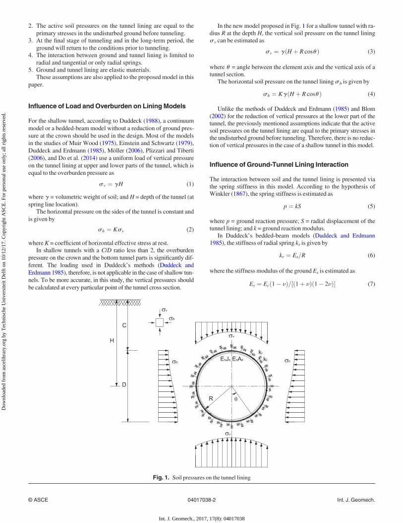
In the newmodel proposed in Fig. 1 for a shallow tunnel with ra-dius R at the depth H, the vertical soil pressure on the tunnel linings v can be estimated as
s v ¼ gðH þ R cosu Þ (3)
where u = angle between the element axis and the vertical axis of atunnel section.
The horizontal soil pressure on the tunnel liningsh is given by
sh ¼ KgðH þ R cosu Þ (4)
Unlike the methods of Duddeck and Erdmann (1985) and Blom(2002) for the reduction of vertical pressures at the lower part of thetunnel, the previously mentioned assumptions indicate that the activesoil pressures on the tunnel lining are equal to the primary stresses inthe undisturbed ground before tunneling. Therefore, there is no reduc-tion of vertical pressures in the case of a shallow tunnel in this model.
Influence of Ground-Tunnel Lining Interaction
The interaction between soil and the tunnel lining is presented viathe spring stiffness in this model. According to the hypothesis ofWinkler (1867), the spring stiffness is estimated as
p ¼ kS (5)
where p = ground reaction pressure; S = radial displacement of thetunnel lining; and k = ground reaction modulus.
In Duddeck’s bedded-beam models (Duddeck and Erdmann1985), the stiffness of radial spring kr is given by
kr ¼ Es=R (6)
where the stiffness modulus of the ground Es is estimated as
Es ¼ Ecð1� �Þ=½ð1þ �Þð1� 2�Þ� (7)
Fig. 1. Soil pressures on the tunnel lining
© ASCE 04017038-2 Int. J. Geomech.
Int. J. Geomech., 2017, 17(8): 04017038
Dow
nloa
ded
from
asc
elib
rary
.org
by
Tec
hnis
che
Uni
vers
iteit
Del
ft o
n 10
/12/
17. C
opyr
ight
ASC
E. F
or p
erso
nal u
se o
nly;
all
righ
ts r
eser
ved.

whereEc = elasticity modulus of the ground; and � = Poisson’s ratio.These methods use a constant spring stiffness for every point on
the tunnel lining based on the stiffness modulus of the ground andPoisson’s ratio �. This is not appropriate because the spring stiff-ness of each point on the tunnel lining is different due to the stressstate of the soil and the change of the deformation pattern of the tun-nel lining.
Oreste (2007) and Do et al. (2014) use a nonlinear relationshipbetween the reaction pressure of the ground p and the deformation
of the tunnel lining d in Duddeck’s model (Duddeck and Erdmann1985) to calculate internal forces in the tunnel lining. The apparentstiffness of the ground h* is estimated as
h� ¼ plimd
1� plimplim þ h0d
� �(8)
where plim = maximum reaction pressure that the ground can offer;and h0 = initial stiffness of the ground (for the d value close to 0).
Fig. 2. Radial and tangentialWinkler springs in FEM analysis (adapted fromDo et al. 2014)
Fig. 3. Measuring field at Second Heinenoord Tunnel (reprinted from Broere 2001, with permission)
© ASCE 04017038-3 Int. J. Geomech.
Int. J. Geomech., 2017, 17(8): 04017038
Dow
nloa
ded
from
asc
elib
rary
.org
by
Tec
hnis
che
Uni
vers
iteit
Del
ft o
n 10
/12/
17. C
opyr
ight
ASC
E. F
or p
erso
nal u
se o
nly;
all
righ
ts r
eser
ved.

For a circular tunnel in elastic ground, the interaction betweenground and the tunnel lining depends on the radius R of the tunnellining and the ground parameters. The initial radial ground reactionstiffness h r,0 is estimated as the following empirical formula(Möller 2006):
h r;0 ¼ b1
1þ �
ER
(9)
where E = Young’s modulus of the ground; and b = dimensionlessfactor.
The value of b depends on soil and structural parameters, there-fore, it is difficult to determine the exact b value. In conventionalstudies of Mashimo and Ishimura (2005), Möller (2006), Plizzariand Tiberti (2006), and Molins and Arnau (2011), the value of b istaken equal to 1. In Do et al. (2014), the value of b is taken equal to2 compared with the Einstein and Schwart’s (1979) method. In thisstudy, the value of b = 2 is used in the analysis to determine theimpact of the depth of cover on internal forces and deformations ofthe tunnel lining.
According to Mashimo and Ishimura (2005), Möller (2006),Plizzari and Tiberti (2006), and Molins and Arnau (2011), the sim-ple relationship between tangential spring stiffness h s and normalspring stiffness h r is
h s ¼13hn (10)
The maximum radial reaction pressure pn,lim in Eq. (8) can becalculated as
pn;lim ¼ 2c cos w1� sin w
þ 1þ sin w1� sin w
Ds conf (11)
where c = cohesion; w = friction angle; andDs conf = confining pres-sure on the tunnel perimeter estimated as
Ds conf ¼ sh þ s v
2�
1� �(12)
Similar to Do et al. (2014), the maximum shear reaction pressureon the tunnel lining in Eq. (8) can be estimated as
ps;lim ¼ s h þ s v
2tan w (13)
The stiffness of the radial springs kn,i and tangential springs ks,iin each element of the frame is
kn;i ¼ h �n;i
Li�1 þ Li2
� �¼ pn;lim
d n;i1� pn;lim
pn;lim þ h n;0d n;i
� � Li�1 þ Li2
(14)
ks;i ¼ h �s;i
Li�1 þ Li2
� �¼ ps;lim
d s;i1� ps;lim
ps;lim þ h s;0d s;i
� � Li�1 þ Li2
(15)
where Li = distance between node ith and node (iþ 1)th (Fig. 2).The values of pn,lim and ps,lim are estimated as Eqs. (11)–(13) foreach integration element of the tunnel lining (here 360 elements of1° segment) as detailed in Do et al. (2014).
The radial springs are only active in the compression condition.It means that in the area in which the tunnel moves away from thesoil the radial springs are inactive.T
able
1.Descriptio
nof
LayersandSo
ilPa
rametersfortheNorthBankof
theSe
cond
Heineno
ordTun
nel(Datafrom
Bakker2
000)
Symbo
lSo
iltype
Top
oflayer
(m)N
.A.P.
Unitw
eigh
t,gwet(g
dry)(kN
=m
3)
Und
rained
shear
streng
th,c
u(kPa
)Coh
esion,
c(kPa
)Frictio
nangle,
w0 ðd
egreesÞ
Poisson’s
ratio
,�(−)
Elasticmod
ulus,
E(M
Pa)
Earth
pressure
coefficient,K0(−)
OAþOBþ1
Mixtureof
sand
andclay
þ2.50
17.2(16.5)
—3
270.34
5.2
0.58
3Sa
nd,localpartsof
clay
−1.50
19.5
—0
350.3
260.47
2Sa
ndwith
clay
0–5.75
19—
033
0.31
250.47
18Sa
nd,localpartsof
clay
−10
.00
20.5
—0
36.5
0.3
400.45
32Sa
nd,gravel
−17
.25
20.5
—0
36.5
0.3
600.5
38A
Clay,localpartsof
sand
−20
.75
20.0
140
731
0.32
160.55
38F
Sand
−25
21—
037
.50.3
800.55
38A
Clay,localpartsof
sand
−26
.520
.014
07
310.32
160.55
Note:OA,O
B=man-m
adefills;N
.A.P.=
Nieuw
AmsterdamPe
il(D
utch
referencelevel,approx
.meansealevel).
© ASCE 04017038-4 Int. J. Geomech.
Int. J. Geomech., 2017, 17(8): 04017038
Dow
nloa
ded
from
asc
elib
rary
.org
by
Tec
hnis
che
Uni
vers
iteit
Del
ft o
n 10
/12/
17. C
opyr
ight
ASC
E. F
or p
erso
nal u
se o
nly;
all
righ
ts r
eser
ved.
Case Study of Second Heinenoord Tunnel
The validation of the newmodel is performed with the case study ofthe Second Heinenoord Tunnel in the Netherlands. A tunnel with anouter diameter of 8.3 m was constructed below the OudeMaas riverin Rotterdam between 1996 and 1999. In this project there were two
measurement locations, one on the North Bank and one on theSouth Bank. The layout of the measurement field at the North Bankis shown in Fig. 3. Measurement instruments were installed in allseven elements of a ring to derive the stress distribution in the ring.Pressure cells were installed on the outer face of segments with twocells per segment on seven segments. During the construction,bending moments and normal forces in the lining were measuredusing strain gauges.
On the North Bank, the tunnel axis is located at about 16.25 mbelow the surface. With a tunnel diameter of 8.3 m, the C/D ratio atthis location is approximately 2. The description of soil layers andsoil parameters are shown in Table 1.
A back-analysis with two-dimensional (2D) FEM PLAXISwas performed as indicated in Bakker (2003). The soil propertiesused were K = 0.5 and g = 18 kN/m3, and the tunnel is located atC/D = 2 with a lining thickness d = 0.35 m. The derived bendingmoments and normal forces from the PLAXIS model were com-pared with the measured data in the North Bank. Moreover, athree-dimensional (3D) model with ANSYS FEM software (Fig.4) was also analyzed to derive bending moments in the tunnel lin-ing in this case (Bakker et al. 2000). In this analysis, the concretesegments were modeled as solid volume segments. Three ringswere modeled using 8,100 elements. In this model, the interac-tion between the tunnel lining and the surrounding ground wasmodeled as linear springs in the radial direction, as in Duddeckand Erdmann (1985), with 1,418 spring elements in total. Thebending moments were derived with three rings and were com-pared with the field data.
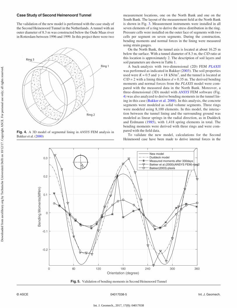
To validate the new model, calculations for the SecondHeinenoord case have been made to derive internal forces in the
Ring 3
Ring 1
Ring 2
Fig. 4. A 3D model of segmental lining in ANSYS FEM analysis inBakker et al. (2000)
Orientation (degree)0 60 120 180 240 300 360
Ben
ding
Mom
ents
(MN
m)
-0.2
-0.1
0
0.1
0.2
0.3New modelDuddeck modelMeasured moments after 330daysBakker et al.(2000)(ANSYS FEM)-ring2Bakker(2003)-plaxis
Fig. 5. Validation of bending moments in Second Heinenoord Tunnel
© ASCE 04017038-5 Int. J. Geomech.
Int. J. Geomech., 2017, 17(8): 04017038
Dow
nloa
ded
from
asc
elib
rary
.org
by
Tec
hnis
che
Uni
vers
iteit
Del
ft o
n 10
/12/
17. C
opyr
ight
ASC
E. F
or p
erso
nal u
se o
nly;
all
righ
ts r
eser
ved.

lining. The derived bendingmoments and normal forces from the newmodel are compared with the field data after 330 days and the analyti-cal results fromBakker et al. (2000), as shown in Figs. 5 and 6.
A comparison among the bending moments derived from the newmodel and the bending moments from measurements in this project,Duddeck’s bedded-beam model (Duddeck and Erdmann 1985), 2DPLAXIS model, and the 3D ANSYS model from Bakker et al. (2000)is shown in Fig. 5. This figure shows that bending moments derivedfrom these models have the same bending moment trend as themeasured data in the field. The bending moment derived from thenew model is close to the moments derived from Duddeck’s modeland Bakker’s 3D analysis by ANSYS. In comparison with the fielddata, the highest bending moment observed in the field data is closeto the bending moments in all these models (at the location of 166°on the cross section of the tunnel lining). Even though there exists adifference between the measured bending moment at the sides of thetunnel lining, the highest bending moment at the top and the bottomof the tunnel lining shows an agreement between the field data andthe analytical models.
Fig. 6 shows a comparison of normal forces between fielddata and normal forces derived from Duddeck’s model (Duddeckand Erdmann 1985), Bakker’s 2D PLAXIS model (Bakker et al.2000), and the new model. Overall, normal forces calculatedfrom these models have the same trend with measured normalforces in field data. From this figure, it can be seen that the nor-mal force from the new model is closer to the field data than theresults from Duddeck’s model and Bakker’s 2D PLAXIS model,especially at locations at the sides of the tunnel lining, althoughthere still exists a difference between the analytical results and
measured normal forces. It was explained in Bakker (2003) thatthe accuracy of the soil pressure gauges on the segments wasunclear, and the influence of the grout injection pressure was nottaken into account at the measured time of 330 days. This mightalso explain the strong variability in the measurement.
On the basis of this analysis, it is shown that the results derivedfrom the new model have the same trend as the analysis resultsfrom previous numerical models and have a better agreementwith the field data. In this case study with C/D = 2, the differencebetween these models is not very large, but for tunnels at shal-lower locations, the differences are expected to be larger.Unfortunately, detailed field measurements at the shallow over-burden are lacking.
Comparing the Impacts of Overburden on theTunnel Lining
Structural analysis is performedwith Duddeck’s bedded-beammodeland the new model with and without buoyancy conditions in themodel, as can be seen in Fig. 1. A circular tunnel with radiusD = 6.3m in soil condition with parameters K = 0.5, � = 0.2, g = 20 kN/m3,and E = 20,000 kN/m2 has been analyzed and compared with theresults in Duddeck and Erdmann (1985).
When comparing the internal forces derived from other methodsof Ahrens et al. (1982), Windels (1967), Muir Wood (1976), andEinstein and Schwartz (1979), Duddeck and Erdmann (1985) usedthe following relative stiffness to investigate the effect of soil prop-erties on the internal forces in the tunnel lining:
Orientation (degree)0 60 120 180 240 300 360
Nor
mal
forc
e(M
N)
0
0.2
0.4
0.6
0.8
1
1.2
1.4
1.6
New modelDuddeck modelMeasured moments after 330daysBakker(2003)-plaxis
Fig. 6. Validation of normal forces in Second Heinenoord Tunnel
© ASCE 04017038-6 Int. J. Geomech.
Int. J. Geomech., 2017, 17(8): 04017038
Dow
nloa
ded
from
asc
elib
rary
.org
by
Tec
hnis
che
Uni
vers
iteit
Del
ft o
n 10
/12/
17. C
opyr
ight
ASC
E. F
or p
erso
nal u
se o
nly;
all
righ
ts r
eser
ved.

aD ¼ ER3
ElIl(16)
where ElIl = bending stiffness of the tunnel lining. This relativestiffness is also used in analysis results from the new model andDuddeck’s model (Duddeck and Erdmann 1985).
In Figs. 7 and 8, the maximum bending moments M are calcu-lated for a range of values of the relative stiffness aD and plottednormalized tom, withm defined as
maxM ¼ ms vR2 (17)
C(m)0 10 20 30 40 50 60 70
m
0
0.02
0.04
0.06
0.08
0.1
0.12
0.14
0.16New modelDuddeck
Fig. 8. Normalized maximum bending momentsm in models with various values of cover depthC
Fig. 7. Normalized maximum bending moments in models with various relative stiffnessaD values
© ASCE 04017038-7 Int. J. Geomech.
Int. J. Geomech., 2017, 17(8): 04017038
Dow
nloa
ded
from
asc
elib
rary
.org
by
Tec
hnis
che
Uni
vers
iteit
Del
ft o
n 10
/12/
17. C
opyr
ight
ASC
E. F
or p
erso
nal u
se o
nly;
all
righ
ts r
eser
ved.

where s v = vertical soil pressure at the tunnel spring line; and m =normalized maximummoment.
Fig. 7 shows a comparison between the normalized maximummoments m derived from the new model and Duddeck’s model(Duddeck and Erdmann 1985) in various relative stiffness aD of soiland the tunnel lining. Overall, the normalized maximum bendingmoments of the new model show the same trend as Duddeck’smodel but have greater values. With the greater aD value corre-sponding with stiffer ground or more flexible tunnel linings, the nor-malized maximum moments m derived from the new model arecloser to these moments from Duddeck’s model.
Fig. 8 shows the changes of the normalized maximum bend-ing moments m derived from these models with the cover depthof the tunnel C. With Duddeck’s method (Duddeck andErdmann 1985), the m value does not change with varied depthsof the tunnel (in this case m = 0.083). Meanwhile, the m valuein the new model is greater than in Duddeck’s model andbecomes constant and close to the m value of Duddeck’s modelwhen the tunnel is at great depths. In the range of C from 0 to12.6 m or C/D from 0 to 2 in the case of shallow tunnels, the mvalue in the new model is much higher than the m value inDuddeck’s model. Especially for tunnels close to the surface
C(m)0 2 4 6 8 10
max
imum
rad
ial d
ispl
acem
ent(
m)
0
0.005
0.01
0.015
0.02
0.025
0.03
0.035
0.04
0.045without buoyancywith buoyancyDuddeck
Fig. 10. Maximum radial displacements in models in shallow tunnels
C(m)0 10 20 30 40 50 60 70
max
imum
rad
ial d
ispl
acem
ent(
m)
0
0.01
0.02
0.03
0.04
0.05
0.06
0.07Without buoyancyWith buoyancyDuddeck
Fig. 9. Maximum radial displacements in models with varied values of cover depthC
© ASCE 04017038-8 Int. J. Geomech.
Int. J. Geomech., 2017, 17(8): 04017038
Dow
nloa
ded
from
asc
elib
rary
.org
by
Tec
hnis
che
Uni
vers
iteit
Del
ft o
n 10
/12/
17. C
opyr
ight
ASC
E. F
or p
erso
nal u
se o
nly;
all
righ
ts r
eser
ved.

(the cover depth C � 0 m), the m value in the new model isdouble that in Duddeck’s model. This stems from the previouslymentioned analysis of the loading in the tunnel lining models.In Duddeck’s model, the loading on the tunnel lining isassumed as symmetric loading in both vertical and horizontalaxes of the tunnel. This leads to the maximum bendingmoments appearing at the top and at the bottom of the tunnelcross section and having the same value. In the new model, theloading on the tunnel lining changes with the depth of a particu-lar point of the tunnel cross section. Consequently, the bendingmoments at the top and at the bottom of the tunnel cross section
are different. In shallow tunnels, the loading at the bottom ofthe tunnel lining is significantly greater than the overburdenloadings at the top and at the spring line of the tunnel lining.Therefore, the normalized maximum bending moment m in thenew model is much greater than in Duddeck’s model in the caseof shallow tunnels, which also means that the maximum bend-ing moment calculated from the new model is significantlygreater than the maximum bending moment calculated fromDuddeck’s model. The larger bending moment generatesgreater deformations of the tunnel lining; thus, there are largersoil movements around the tunnel lining. These large soil
C/D0 0.5 1 1.5 2 2.5
max
imum
rad
ial d
ispl
acem
ent(
m)
0
0.02
0.04
0.06
0.08
0.1
0.12
0.14
0.16
0.18
0.2
R=3-without buoyancyR=4-without buoyancyR=5-without buoyancyR=6-without buoyancyR=3-with buoyancyR=4-with buoyancyR=5-with buoyancyR=6-with buoyancy
C/D0 0.5 1 1.5 2 2.5
max
imum
rad
ial d
ispl
acem
ent(
m)
0
0.02
0.04
0.06
0.08
0.1
0.12
0.14
0.16
0.18
0.2
R=3-without buoyancyR=4-without buoyancyR=5-without buoyancyR=6-without buoyancyR=3-with buoyancyR=4-with buoyancyR=5-with buoyancyR=6-with buoyancy
(a)
(b)
Fig. 11. Relationship between maximum radial displacements and cover-to-diameter C/D values for models with and without buoyancy in variedthickness-to-diameter ratios d/D of the tunnel cross section (vertical lines include the optimal C/D, in which radial displacement is minimal): (a) d/D =1/10; (b) d/D = 1/20; (c) d/D = 1/40
© ASCE 04017038-9 Int. J. Geomech.
Int. J. Geomech., 2017, 17(8): 04017038
Dow
nloa
ded
from
asc
elib
rary
.org
by
Tec
hnis
che
Uni
vers
iteit
Del
ft o
n 10
/12/
17. C
opyr
ight
ASC
E. F
or p
erso
nal u
se o
nly;
all
righ
ts r
eser
ved.

movements can influence the spring stiffness. However, thisimpact is not taken into account in this study because theground is assumed as an elastic material, as indicated in theprevious assumptions, and the springs are linear elastic. Whenthe tunnel is at greater depths, the loading in the new modelconverges to the loading in Duddeck’s model, even though asmall difference between the loadings at the top and at the bot-tom of the tunnel lining remains. The normalized maximumbending moment m in the new model, therefore, becomesnearly equal to the m value in Duddeck’s model in this case.
One of the most important considerations in tunnel design isthe deformation of the tunnel lining. Figs. 9 and 10 show thechanges of maximum radial displacements in these models atvarious depths of the tunnel. In Fig. 9, in the analysis resultsobtained from Duddeck’s model (Duddeck and Erdmann1985), the maximum radial displacement of the tunnel liningincreases linearly with an increase in tunnel depth. When thetunnel is located below the water level, there is an upwardforce equal to the displaced volume of water. This phenomenonis known as buoyancy. This trend also appears in the new
C/D0 0.5 1 1.5 2 2.5
max
imum
rad
ial d
ispl
acem
ent(
m)
0
0.02
0.04
0.06
0.08
0.1
0.12
0.14
0.16
0.18
0.2
R=3-without buoyancyR=4-without buoyancyR=5-without buoyancyR=6-without buoyancyR=3-with buoyancyR=4-with buoyancyR=5-with buoyancyR=6-with buoyancy
(c)
Fig. 11. (Continued.)
Fig. 12. Optimal cover-to-diameter ratioC/D values for shallow tunnels (for soil withK = 0.5, � = 0.2, g = 20 kN/m3, andE = 20,000 kN/m2)
© ASCE 04017038-10 Int. J. Geomech.
Int. J. Geomech., 2017, 17(8): 04017038
Dow
nloa
ded
from
asc
elib
rary
.org
by
Tec
hnis
che
Uni
vers
iteit
Del
ft o
n 10
/12/
17. C
opyr
ight
ASC
E. F
or p
erso
nal u
se o
nly;
all
righ
ts r
eser
ved.
model with and without buoyancy for moderate and deep tun-nels (C ≥ 6.3m or C/D ≥ 2). Maximum radial displacement inthe new model with buoyancy is higher than that in Duddeck’smodel due to the higher maximum bending moments, as indi-cated in the previously mentioned analysis.
Fig. 10 shows the change in the maximum radial displacementin the case of shallow tunnels (C/D ≤ 2). Maximum radial dis-placements in the new model with and without buoyancy arehigher than the maximum radial displacement in Duddeck’smodel (Duddeck and Erdmann 1985). In the analysis resultsfrom Duddeck’s model, the maximum radial displacementdecreases linearly to nearly 0 when the tunnel is close to the sur-face. Clearly, this is not appropriate for practical cases.Therefore, it might be risky when applying Duddeck’s model indesigning very shallow tunnels. For very shallow tunnels (C/Dfrom 0 to 1 or C from 0 to 6.3 m in this paper), the maximum ra-dial displacement increases sharply in the buoyancy model andsignificantly in the model without buoyancy when the tunnel isnear the surface. If one compares the two, then the maximum ra-dial displacements in the buoyancy model are two to three timeshigher than displacements in the model without buoyancy. Thishappens when the tunnel is close to the surface because the rela-tive difference in the loading on the upper and lower parts of thetunnel lining increases more both for soil loading and porepressure.
From the maximum radial displacement lines of the newmodel given in Fig. 10, there are lowest points with and withoutbuoyancy. This indicates the existence of an optimal depth for aparticular tunnel in which maximum deformation is minimalboth with and without buoyancy. In this case study, the optimaldepth is estimated at the depth of the tunnel H = 8.5 m or thecover depth C = 5.35 m, in which the minimum values of maxi-mum displacements in models with and without buoyancy are0.02 and 0.01 m, respectively.
Analyzing for varied tunnel radii R and the thickness-to-diameter d/D ratio of cross sections in the new model with andwithout buoyancy, Fig. 11 shows the relationship betweenmaximum radial displacements and the C/D ratio. At a particu-lar value of the C/D ratio, the thinner the tunnel cross sectionand/or the larger the tunnel radius is, the larger is the maximumradial displacement. It is interesting to note the existence of avalue of the C/D ratio in which the maximum radial displace-ment is minimum for a particular d/D ratio with varied tunnelradii R both with and without buoyancy. In Fig. 11(a) for thetunnel with cross section d/D = 1/10, the maximum displace-ment of the tunnel lining reaches the minimum value whenC/D = 2.05 for the models with and without buoyancy. Theseoptimal values are 0.8 for the tunnel with cross section d/D =1/20 in Fig. 11(b) and 0.48 for the tunnel with cross sectiond/D = 1/40 in Fig. 11(c).
On the basis of this structural analysis for shallow tunnels in softsoil, for a varied geometry of the cross section of the tunnel d/D, anoptimal C/D value can be found that gives a minimum value of themaximum deformation of the tunnel lining. Moreover, uplift analy-sis for shallow tunnels in Vu et al. (2015) provides the minimumC/D ratio in which ballast should be used for varied values of d/D.From Fig. 12, the optimalC/D value based on the structural analysisand uplift analysis for shallow tunnels with or without buoyancycan be determined. The intersection between the optimal values ofthe C/D ratio from structural analysis and uplift analysis shows adesigned shallow tunnel in which ballast layers are required or inwhich the value of the d/D ratio should be minimally used in a par-ticular depth of the tunnel.
Conclusions
Structural design for tunnels has been previously focused onmoder-ate to deep tunnels (C/D ≥ 2). The loading on tunnel linings inrecent models does not include the difference of loadings at the topand at the bottom of shallow tunnels. By calculating the soil pres-sure at particular points on the cross section of the tunnel combinedwith the FEM for structural analysis, the new model in this studybecomes appropriate for tunnels at shallow depths. Structural analy-sis from the new model shows that the normalized internal forcesand the deformations of the tunnel lining increase significantlywhen the tunnel is designed at shallow location with and withoutbuoyancy. From the analysis results it follows that there is a mini-mum value of maximum deformation of the tunnel lining whenchanging the cover depth C of the tunnel. From combined structuralanalysis with uplift analysis, an optimal cover-to-diameter ratioC/D value for a particular cross section d/D value in tunneling with-out ballast can be derived.
References
ANSYS [Computer software]. ANSYS, Canonsburg, PA.Ahrens, H., Lindner, E., Lux, K. H. (1982). “Zur dimensionierung von tun-
nelausbauten nach empfehlungen zur berechnung von tunneln im lock-ergestein, 1980.” Bautechnik, 59(8), 260–273.
Bakker, K. (2003). “Structural design of linings for bored tunnels in softground.”Heron, 48(1), 33–64.
Bakker, K., Leendertse, W., Jovanovic, R., and van Oosterhout, G. (2000).“Monitoring: Evaluation of stresses in the lining of the SecondHeinenoord Tunnel.” Geotechnical aspects of underground construc-tion in soft ground, A. A. Balkema, Tokyo, 197–202.
Bakker, K. J. (2000). Soil retaining structures: Development of models forstructural analysis, A. A. Balkema, Rotterdam, Netherlands.
Blom, C. B.M. (2002). “Design philosophy of concrete linings for tunnels in softsoils.”Ph.D. thesis, TUDelft, Delft Univ. of Technology, Delft, Netherlands.
Broere, W. (2001). “Tunnel face stability & new CPT applications.”Doctoral thesis, TU Delft, Delft Univ. of Technology, Delft,Netherlands.
Do, N.A., Dias, D., Oreste, P., andDjeran-Maigre, I. (2014). “Anew numeri-cal approach to the hyperstatic reaction method for segmental tunnel lin-ings.” Int. J. Numer. Anal. Methods Geomech., 38(15), 1617–1632.
Duddeck, H. (1988). “Guidelines for the design of tunnels.” TunnellingUnderground Space Technol., 3(3), 237–249.
Duddeck, H., and Erdmann, J. (1985). “On structural design models for tun-nels in soft soil.” Underground space, Vol. 9, Pergamon Press, Oxford,U.K., 246–259.
Einstein, H. H., and Schwartz, C. W. (1979). “Simplified analysis for tun-nel supports.” J. Geotech. Eng. Div., Am. Soc. Civ. Eng., 105(4), 499–518.a66.
Groeneweg, T. (2007). “Shield driven tunnels in ultra high strength con-crete: Reduction of the tunnel lining thickness.”M.Sc. thesis, TU Delft,Delft Univ. of Technology, Delft, Netherlands.
Mashimo, H., and Ishimura, T. (2005). “Numerical modelling of the behav-ior of shield tunnel lining during assembly of a tunnel ring.” Proc., 5thInt. Symp. Geotechnical Aspects of Underground Construction in SoftGround, Taylor& Francis, Amsterdam, Netherlands, 587–593.
Molins, C., and Arnau, O. (2011). “Experimental and analytical study of thestructural response of segmental tunnel linings based on an in situ load-ing test. Part 1: Test configuration and execution.” TunnellingUnderground Space Technol., 26(6), 764–777.
Möller, S. C. (2006). “Tunnel induced settlements and structural forces inlinings.” Ph.D. thesis, Univ. Stuttgart, Inst. f. Geotechnik, Stuttgart,Germany.
Morgan, H. (1961). “A contribution to the analysis of stress in a circular tun-nel.”G�eotechnique, 11(1), 37–46.
Muir Wood, A. M. (1975). “The circular tunnel in elastic ground.”G�eotechnique, 25(1), 115–127.
© ASCE 04017038-11 Int. J. Geomech.
Int. J. Geomech., 2017, 17(8): 04017038
Dow
nloa
ded
from
asc
elib
rary
.org
by
Tec
hnis
che
Uni
vers
iteit
Del
ft o
n 10
/12/
17. C
opyr
ight
ASC
E. F
or p
erso
nal u
se o
nly;
all
righ
ts r
eser
ved.

Muir Wood, A. M. (1976). “Discussion: The circular tunnel in elasticground.”G�eotechnique, 26(1), 231–237.
Oreste, P. (2007). “A numerical approach to the hyperstatic reaction methodfor the dimensioning of tunnel supports.” Tunnelling UndergroundSpace Technol., 22(2), 185–205.
PLAXIS [Computer software]. PLAXIS, Delft, Netherlands.Plizzari, G., and Tiberti, G. (2006). “Steel fibers as reinforcement for precast
tunnel segments.” Tunnelling Underground Space Technol., 21(3),438–439.
Schmid, H. (1926). Statische probleme des tunnel-und druckstollenbauesund ihre gegenseitigen beziehungen, Springer, Berlin.
Schulze, H., and Duddeck, H. (1964). “Spannungen in schildvorgetriebenentunneln.” Beton-und Stahlbetonbau, 59(8), 169–175.
Vu, M. N., Broere, W., and Bosch, J. W. (2015). “The impact of shallowcover on stability when tunnelling in soft soils.” TunnellingUnderground Space Technol., 50, 507–515.
Windels, R. (1966). “Spannungstheorie zweiter ordnung für den teilweisegebetteten kreisring.”Die Bautechnik, 43, 265–274.
Windels, R. (1967). “Kreisring im elastischen continuum.” Der BauingenieurBd, 42, 429.
Winkler, E. (1867). Theory of elasticity and strength, Dominicus Prague,Prague, Czech Republic.
© ASCE 04017038-12 Int. J. Geomech.
Int. J. Geomech., 2017, 17(8): 04017038
Dow
nloa
ded
from
asc
elib
rary
.org
by
Tec
hnis
che
Uni
vers
iteit
Del
ft o
n 10
/12/
17. C
opyr
ight
ASC
E. F
or p
erso
nal u
se o
nly;
all
righ
ts r
eser
ved.


![Zeitengetriebe RZ neu web - Eduard Erdmann … Linearität - Eduard Erdmann und Heinz Tiessen] Christoph Schlüren , München 16H30 „Hüten Sie sich vor Geschicklichkeit!“ –](https://static.fdocuments.net/doc/165x107/5ad8e7087f8b9af9068e1c2e/zeitengetriebe-rz-neu-web-eduard-erdmann-linearitt-eduard-erdmann-und-heinz.jpg)