Delft University of Technology Aeroelastic Optimization of...
19
Delft University of Technology Aeroelastic Optimization of Variable Stiffness Composite Wing with Blending Constraints Bordogna, Marco Tito; Macquart, Terence; Bettebghor, D.; De Breuker, Roeland DOI 10.2514/6.2016-4122 Publication date 2016 Document Version Peer reviewed version Published in 17th AIAA/ISSMO Multidisciplinary Analysis and Optimization Conference Citation (APA) Bordogna, M. T., Macquart, T., Bettebghor, D., & De Breuker, R. (2016). Aeroelastic Optimization of Variable Stiffness Composite Wing with Blending Constraints. In 17th AIAA/ISSMO Multidisciplinary Analysis and Optimization Conference : Washington, USA [AIAA 2016-4122] AIAA. DOI: 10.2514/6.2016- 4122 Important note To cite this publication, please use the final published version (if applicable). Please check the document version above. Copyright Other than for strictly personal use, it is not permitted to download, forward or distribute the text or part of it, without the consent of the author(s) and/or copyright holder(s), unless the work is under an open content license such as Creative Commons. Takedown policy Please contact us and provide details if you believe this document breaches copyrights. We will remove access to the work immediately and investigate your claim. This work is downloaded from Delft University of Technology. For technical reasons the number of authors shown on this cover page is limited to a maximum of 10.
Transcript of Delft University of Technology Aeroelastic Optimization of...

Delft University of Technology
Aeroelastic Optimization of Variable Stiffness Composite Wing with BlendingConstraints
Bordogna, Marco Tito; Macquart, Terence; Bettebghor, D.; De Breuker, Roeland
DOI10.2514/6.2016-4122Publication date2016Document VersionPeer reviewed versionPublished in17th AIAA/ISSMO Multidisciplinary Analysis and Optimization Conference
Citation (APA)Bordogna, M. T., Macquart, T., Bettebghor, D., & De Breuker, R. (2016). Aeroelastic Optimization ofVariable Stiffness Composite Wing with Blending Constraints. In 17th AIAA/ISSMO MultidisciplinaryAnalysis and Optimization Conference : Washington, USA [AIAA 2016-4122] AIAA. DOI: 10.2514/6.2016-4122Important noteTo cite this publication, please use the final published version (if applicable).Please check the document version above.
CopyrightOther than for strictly personal use, it is not permitted to download, forward or distribute the text or part of it, without the consentof the author(s) and/or copyright holder(s), unless the work is under an open content license such as Creative Commons.
Takedown policyPlease contact us and provide details if you believe this document breaches copyrights.We will remove access to the work immediately and investigate your claim.
This work is downloaded from Delft University of Technology.For technical reasons the number of authors shown on this cover page is limited to a maximum of 10.

Aeroelastic Optimization of Variable Stiffness CompositeWing with Blending Constraints
Marco Tito Bordogna1 3 * Terence Macquart2 †Dimitri Bettebghor1 ‡
and Roeland De Breuker3 §
1ONERA - The French Aerospace Lab F-92260, Chatillon, France2University of Bristol, Bristol, England BS8 1TR, United Kingdom
3Delft University of Technology, 2629 HS Delft, The Netherlands
Abstract
Optimizing the laminates of large composite structures is nowadays well-recognized as havingsignificant benefits in the design of lightweight structural solutions. However, designs based onlocally optimized laminates are prone to structural discontinuities and enforcing blending duringthe optimization is therefore crucial in order to achieve structurally continuous and ready-to-manufacture designs. Bi-step strategies, relying on a continuous gradient-based optimizationof lamination parameters followed by a discrete stacking sequence optimization step duringwhich blending is enforced, have been proposed in the literature. However, significant mismatchbetween continuous and discrete solutions were observed due to the discrepancies betweenboth design spaces. The present paper highlights the capability of the continuous blendingconstraints, recently proposed by the authors, in reducing the discrepancies between discreteand continuous solutions. The paper also demonstrates that more realistic optimal continuousdesigns are achieved thanks to the application of the blending constraints during the aeroelasticoptimization of a variable stiffness wing. Additionally, the proposed blending constraints havebeen applied to NASTRAN SOL 200 showing their ease of implementation in commercial software.
1 Introduction
The use of composite materials in the aerospace industry is increasing steadily due to the high stiff-ness and strength to weight ratios of carbon fiber reinforced polymers (CFRP) with respect to theirmore conventional aluminium counterparts, making them ideal for lightweight structure design.Another distinctive characteristic of composites, as opposed to metals, is the possibility to adjusttheir anisotropic behavior by changing the stacking sequence of laminates. By doing so, compositematerials allow structural designers to specifically tailor structures according to the loads they arepredicted to experience. Commonly employed in the literature, the improved stiffness design of alarge composite structure is obtained by dividing it into sub-structures or sections each optimized
*Ph.D. Candidate, Faculty of Aerospace Engineering, Aerospace Structures and Computational Mechanics, TU Delft†Research Associate, Advanced Composite Center for Innovation and Science, Department of Aerospace Engineering,
University of Bristol‡Research Scientist, Département Aéroélasticité et Dynamique des Structures (DADS), ONERA§Assistant Professor, Faculty of Aerospace Engineering, Aerospace Structures and Computational Mechanics, TU Delft
1

with respect to their laminate thickness and stacking sequence. However, this practice reduce theintegrity of the structure due to thickness and/or stacking sequence discontinuities and do not provideany guarantee that the optimized structure could be manufactured [?, ?]. In order to avoid stressconcentrations due to structural discontinuities and to improve manufacturability, blending has to betaken into account throughout the design process in order to ensure ply continuity over the wholestructure.
Ply continuity between structural sections can be imposed in different ways. Inner and outerblending have been introduced by Adams et al. [?] , in these definitions only the innermost and theoutermost plies can be dropped as shown in Figure 1a. Two alternative definitions, the generalizedand relaxed generalized blending, have been formulated by Van Campen et al. [?] and are presentedin Figure 1b. Generalized blending requires all plies of the thinnest section to be continuous in thewhole structure; relaxed generalized blending demands that no discontinuous plies should be indirect physical contact with each other. Throughout this paper, blending is always associated to thegeneralized blending definition of Van Campen et al. [?] for sake of clarity.
(a) (b)
Figure 1: (a) Outward and inward blending, and (b) generalized (I and II) and relaxed generalized (II and III)blending. Original figures from [?] .
Single and multi-step optimizations have been proposed to optimize variable stiffness blendedcomposite structures. Single step methods are usually based on heuristic techniques (e.g. geneticalgorithms [?, ?]) to generate populations of blended solutions. These methods are highly constrainedand have prohibitive computational cost when applied to large scale optimization problems. Multi-step approaches divide the optimization into simpler-to-solve sub-optimization problems. Severalauthors [?, ?, ?, ?] have used bi-step strategies where a gradient-based (continuous) optimization ofhomogenized stiffness parameters (e.g. lamination parameters) is followed by a genetic algorithm(discrete optimization) to retrieve blended stacking sequences. By doing so, mechanical constraints(e.g. stresses and/or buckling) are verified during the continuous step whereas most of the manufac-turing constraints (e.g. blending) are enforced during the discrete step. This bi-step approach canresult in significant discrepancies between the two optimization steps [?] and therefore there is noguarantee to find an equivalent of the optimal continuous design after the discrete step. The onlyviable way to satisfy both mechanical and manufacturing constraints when employing the bi-stepapproach is to couple the genetic algorithm used for stacking sequence retrieval with expensivemechanical constraint evaluations that can be either surrogate-model based or derived via finiteelement calculations.
In view of discontinuities and issues arising due to the bi-step optimization approach, Macquart
et al. [?] proposed employing lamination parameters combined with a set of blending constraintsto be used in the continuous optimization in order to achieve more realistic and manufacturablecontinuous designs and reduce discrepancies between the two steps. In [?] the continuous blendingconstraints have been applied to the benchmark case of the 18 panel horseshoe [?] that has proventheir effectiveness. The derived constraints allowed the continuous optimization to retrieve a morerealistic continuous optimal design and reduced the lamination parameter space in the continuousoptimization so that the continuous optimal design lays close to the discrete one retrieved with thegenetic algorithm. In a continuing effort, Macquart et al. [?] have also demonstrated that the appli-cation of blending constraints during aeroelastic optimizations results in more realistic continuousdesign. Although it was shown that closely matching aeroelastic performance could be achievedduring stacking sequence retrieval, these results are obtained from an in-house code based on Timo-shenko beam structural model. By contrast, the present paper aims at carrying an investigation morerepresentative of the wing design process by including local buckling constraints and a wing shellmodel to be optimized by the NASTRAN commercial finite element software.
This paper is organized as follow. Section 2 briefly introduces the blending constraints. Theoptimization strategy, the wing model and the genetic algorithm used in the discrete step are presentedin Section 3. Finally, Sections 4 and 5 present the results and draw conclusions on the advantagesrelated to using blending constraints during the aeroelastic optimization of the variable stiffnesscomposite wing.
2 Blending Constraints
Lamination parameters have been first introduced by Tsai et al. [?] and are used to describe the stiffnessmatrix of composite laminates in a continuous space. For stacking sequence with discrete plies ofconstant thickness (tpl y ) and ply angle (θi ), lamination parameters are defined in Eqs. (1). In thispaper only symmetric stacking sequence with even number of ply and same thickness are considered,therefore only lamination parameters for membrane (A) and bending (D) stiffness matrices are takeninto account.
(V A1 ,V A
2 ,V A3 ,V A
4 ) = 1
N
N∑i=1
[cos(2θi ),sin(2θi ),cos(4θi ),sin(4θi )]
(V D1 ,V D
2 ,V D3 ,V D
4 ) = 4
N 3
N∑i=1
(Z 3i −Z 3
i−1) [cos(2θi ),sin(2θi ),cos(4θi ),sin(4θi )]
(1)
where, Zi =−N /2+ i .
The key concept for the derivation of the continuous blending constraints is to evaluate the changein lamination parameters (∆V ) due to ply drops. The application of this concept is presented here forderiving the blending constraint for a single in-plane lamination parameter (Eq. (6)). A comprehensivederivation of all the remaining blending constraints (Eqs. (9) and (11)) used in this paper can be foundin [?] .
Lets denote V A1(N ) and V A
1(N−X ) the value of the first in-plane lamination parameter when thelaminate has respectively N and N − X plies. The change in lamination parameter due to a X ply

drops is denoted as ∆V A1(N )→(N−X ) and it is presented in Eq. (4).
V A1(N ) =
1
N
N∑i=1
cos(2θi ) (2)
V A1(N−X ) =
1
N −X
N∑i=X+1
cos(2θi ) (3)
∆V A1(N )→(N−X ) =V A
1(N ) −V A1(N−X ) =
1
N
X∑j=1
cos(2θ j )︸ ︷︷ ︸Term containing the
dropped plies
+(
1
N− 1
N −X
)N−X∑i=1
cos(2θi )︸ ︷︷ ︸Term containing the pliespresent in both sections
(4)
where X is the number of dropped plies, N is the total number of plies, θ j represent the orientation ofthe dropped plies and θi the orientation of the plies left in the stacking sequence. The maximum andminimum value of Eq. (4) occurs respectively for [θ j ,θi ] = [0◦,90◦] and for [θ j ,θi ] = [90◦,0◦] at which∆V A
1(N )→(N−X ) is:
max(θ j ,θi )
||∆V A1(N )→(N−X )|| = 2
X
N(5)
This implies that no blendable solution can be found if, in two adjacent sections, the change inV A
1 is greater than 2(X /N ). By applying the same approach to the remaining in-plane laminationparameters, it can be shown that this limit holds. Thus, it is possible to define a blending constraintfor single in-plane lamination parameter change as:
||∆V Ak(N )→(N−X )|| ≤ 2
X
N, for k = 1,2,3,4 (6)
An analogous procedure can be implemented in the retrieval of a blending constraint for single out-of-plane lamination parameter, also in this case it is possible to obtain a single equation [?] applicableto all four out-of-plane lamination parameters separately. However, applying eight constraints onsingle in-plane and out-of-plane lamination parameters change between all combinations of twodifferent sections in a structure can drastically increase the number of total constraints to take intoaccount during optimization. In order to reduce the number of constraints, the Euclidean distance(Eq. (7)) can be used to take into account the simultaneous change of more that one laminationparameter, leading to Eq. (8) that constrains all four in-plane lamination parameters simultaneously.
(E I P
(N )→(N−X )
)2 =4∑
k=1
(∆V A
k(N )→(N−X )
)2(7)
(E I P
(N )→(N−X )
)2 ≤ 6.25(X /N )2 (8)
Similarly, a constraint can be derived for all four out-of-plane lamination parameters. However,since in this paper only symmetric stacking sequence with even number of plies are taken into account(Figure 2), the in-plane and out-of-plane constraints are written as in Eqs. (9). The scalar value ’6.25’is calculated, like for Eq. (5), by finding the maximum of a summation of trigonometric functionsrepresenting the plies dropped and kept in the laminate [?] . This maximum always corresponds tostacking sequence that are unlikely to be used in aerospace application because they do not followsome of the most common used composite design guidelines [?] like the 10% rule. Therefore, thederived blending constraints are conservative in the sense that they are effective also when composite

design guidelines are not enforced and not conventional stacking sequence are used. Therefore, inorder to tighten the constraints two coefficients α and β have been added. These parameters allowsthe radius of the hypersphere limiting the ∆V to be reduced.
(E I P
(N )→(N−2X )
)2 ≤α 6.25
(2X
N
)2
(EOOP
(N )→(N−2X )
)2 ≤β 6.25
[2
(3
(X
N
)−6
(X
N
)2
+4
(X
N
)3)]2 (9)
Figure 2: Ply-drops illustration for symmetric laminates with even number of plies.
It is also possible to combine both in-plane and out-of-plane lamination parameters change inone single blending constraint by use, one more time, of the Euclidean distance and obtaining Eq. (11).
(E I P,OOP
(N )→(N−2X )
)2 =4∑
k=1
(∆V A
k(N )→(N−2X )
)2 +4∑
k=1
(∆V D
k(N )→(N−2X )
)2(10)
(E I P,OOP
(N )→(N−2X )
)2 ≤ 6.25
α(
2X
N
)2
︸ ︷︷ ︸In-Plane
+β[
2
(3
(X
N
)−6
(X
N
)2
+4
(X
N
)3)]2
︸ ︷︷ ︸Out-of-Plane
(11)
The blending constraints presented here (Eqs. (6), (9) and (11)) limit the change in laminationparameters between adjacent laminates and are function of the thickness change (or ply drops ratioX /N ). However, optimizing at the same time thicknesses and lamination parameters while enforcingconstraints that are function of both, results in a non-convex optimization problem. To overcome thisissue, a the four-step strategy presented in Section 3.1 is adopted.
In order to provide the reader with a visual representation of the constraints, lets take into accountthe situation presented in Figure 3, where a multi-section laminate is subjected to X ply drops from asection with N plies to another with N −X plies. Lets now reproduce this situation in the laminationparameters space for V A
1 and V A2 (Figure 4). In this example the starting laminate section has N equal
to 20 plies and it is used to generate all possible N −X plies blended sections by removing X equal to2 and 4 plies. Blending constraints for the two different ply drops are shown to be capable of includingall possible N −X plies blended sections.
3 Optimization problem
The optimization problem is carried out using a bi-step optimization strategy. First, a gradient basedoptimization (continuous) step optimizes the stiffness matrices of the wing sections via laminationparameters. Second, a genetic algorithm (discrete optimization) is used to retrieve a manufacturable

N plies
N-X plies
V1A
(N)
V1A
(N-X)
X ply drops
Figure 3: Multi-section laminate and ply-drops illustration
-1 -0.5 0 0.5 1
V1
A
-1
-0.5
0
0.5
1
V2
A
Starting Laminate with 20 pliesBlended Laminates with 18 pliesBlended Laminates with 16 pliesFeasible Design Space for V
1 and V
2
Blending Constraint for 2 ply dropsBlending Constraint for 4 ply drops
Figure 4: Example of a 20 plies laminate and all its possible blended laminates with 2 and 4 ply drops.
stacking sequences starting from the continuous results obtained at the first step. The two steps aredescribed respectively in Sections 3.1 and 3.2. Section 3.3 introduce the wing model used togetherwith the load case and the mechanical constraints.
3.1 Continuous optimization via NASTRAN SOL 200
The blending constraints limit the change of lamination parameters between each section as functionof their change in thickness. Applying those constraints while simultaneously optimizing thicknessand lamination parameters leads to a non-convex optimization problem. Therefore, the following4-step strategy is employed (Figure 5).
For the case where blending constraints are enforced. The first step of this algorithm is theconventional convex optimization of the structure thicknesses and lamination parameters withoutblending constraints. This step provides a feasible starting point before the introduction of theblending constraints. The unblended design (XU ) is used as starting point for step 2, where blendingconstraints are considered. In step 3, a repair function rounds up the thicknesses of blended design(XB ) to an even number of plies. After the repaired design (XR ), lamination parameters are optimizedone last time in step 4 while thicknesses are fixed. During this step, the feasibility of the structure ismaximized, meaning that the objective function during this step is to maximize the reserve factors ofall the mechanical constraints. Rounding of thicknesses and maximizing of reserve factors modify

the stiffness of the structure, leading to internal load redistribution. Therefore, step 2-4 are repeateduntil convergence to a final continuous design (XFC ). After the final continuous design is obtained, astacking sequence retrieval GA is employed to retrieve a blended final discrete design (XF D ).
In case blending is not required, step 2 is avoided and steps 1,3-4 are repeated until convergence.The overall strategy is presented in Figure 5.
Figure 5: Proposed optimization strategy including blending constraints.
The optimizer and FEM solver used in this optimization is NASTRAN SOL 200, whereas theproposed strategy is implemented and run externally via Python script. NASTRAN, as well as otheroptimizers, allows the user to combine responses, design variables and model properties (e.g. Youngmodulus or stiffness module) and to define new responses that can be used during optimization. This

capability allowed an easy implementation of the blending constraints inside the optimizer. Othergradient-based optimization tools with comparable capabilities can also be used.
3.2 Discrete optimization via OptiBLESS
The OptiBLESS [?] open source stacking sequence optimization toolbox developed by the authors isused to retrieve manufacturable laminates (https://github.com/TMacquart/OptiBLESS). OptiB-LESS uses a guide-based GA in order to retrieve blended stacking sequences matching the optimizedlamination parameters achieved by the grandient-based optimizer (i.e. NASTRAN). According to theguide-based methodology [?], the thickest laminate is defined as the guide-laminate. Other laminatesfrom the same structure are obtained by dropping plies from the guide-laminate therefore ensuringthe final design is blended. Additionally, manufacturing design guidelines such as the ten percent ruleand the disorientation guideline are enforced during the discrete optimization. The complete list ofcomposite design guidelines can be found in the work of Irisarri et al. [?].
The outcome of the continuous optimization step is used as starting point for the discrete op-timization. After the continuous optimization each wing section is optimized in terms of laminatethickness and lamination parameters. The thickest laminate within each substructure (i.e. skins andspars) is identified and set as the guide. Next, the ply angles describing the guide laminate stackingsequence and ply drops are used as design variables in OptiBLESS. Doing so ensure some level ofstructural continuity between each of the substructure laminates. That is, the plies of thinnest top skinlaminate are ensured to span the entire top skin structure due to the guide-based coding implementedin OptiBLESS.
The genotype used in OptiBLESS to describe composite structures is given as:
Genot y pe =
[θ1 θ2 ... θn]︸ ︷︷ ︸Ply angles
[Ξ1 Ξ2 ... ΞD ]︸ ︷︷ ︸Drop off
(12)
The guide laminate is fully defined by the θ’s. Other laminates are obtained by dropping plies fromthe guide stacking sequence. Since the number of plies associated with each section of structure isknown from the continuous optimization, the ply drop off design variables denote which ply of guidestacking sequence must be dropped. For instance, consider a structure composed of a 5-ply guidelaminate and two other laminates of 4 and 2 plies each. The genotype for such structure would be :
Genot y pe = [[θ1 θ2 θ3 θ4 θ5][Ξ1 Ξ2 Ξ3]] = [[θ1 θ2 θ3 θ4 θ5][1 3 4]] (13)
where the guide stacking sequence is simply [θ1 θ2 θ3 θ4 θ5] and the stacking sequence for 4 and 2plies laminates are respectively [θ2 θ3 θ4 θ5] and [θ2 θ5].
The objective function used during the discrete optimization represents the lamination parametermatching quality between the continuous and discrete design. In other words, OptiBLESS is set toretrieve blended stacking sequences with lamination parameters matching the lamination parametersobtained at the end of the continuous optimization. This objective function is simply expressed asthe root mean square error (RMSE) between the continuous and discrete lamination parameters asshown in Eqs. (14 and 15).

F i tness(θ,Ξ) = 1
Nl am
Nl am∑s=1
RMSEs(θ,Ξ) (14)
RMSEs(θ,Ξ) =√√√√1
8
8∑i=1
(L̃Pi ,s −LPi ,s(θ,Ξ)
)2(15)
where Nl am is the total number of laminate sections in a structural component (i.e. upper wing skin),L̃Pi ,s is the vector of input parameters for section s and LPi ,s is the vector of lamination parametersobtained by the GA. Stacking sequences are converted into lamination parameters in order to evaluatethe fitness using the following notation:
LP = [V A1 V A
2 V A3 V A
4 , V D1 V D
2 V D3 V D
4 ] (16)
According to the fitness function given in Eq. (14), the best retrieved stacking sequence would be amanufacturable stacking sequence exactly matching the optimized lamination parameters obtainedby NASTRAN.
3.3 ONERA Wing Model
An ONERA internal wing model is used as a test case for the blending constraints. The wing modelis characterized by upper and lower skins, front and rear spars, 32 ribs, 13 stringers and represent arealistic aircraft wing (e.g. A320 or B737). Wing dimensions and load case are presented in Table 1.
The wing skins and spars are divided respectively in eleven and five different sections (Figure 6),each section is optimized by means of section thickness (t) and eight lamination parameters (V A
1 ,V A
2 , V A3 , V A
4 , V D1 , V D
2 , V D3 , V D
4 ). Ribs and stiffeners are made of quasi-isotropic stacking sequencesbut are not optimized. The aeroelastic loads are calculated via Doublet Lattice Method (DLM) insideNASTRAN SOL 144, where the aircraft is trimmed. A quasi-isotropic initial design with constantthickness along the wingspan is used as starting point for the continuous optimization.
(a) (b)
Figure 6: (a) Sections of the upper and lower skin, and (b) sections in the front and rear spars plus ribsdistribution.
A part from the bending constraints, other sets of constraints are considered during the optimiza-tion. One set of constraints is represented by the compatibility equations [?, ?], these ensure that eachset of in-plane and out-of-plane lamination parameters leads to a realistic A and D stiffness matrix.

Table 1: Wing features and load case used in the optimization.
Wing geometric characteristicsHalf Wingspan 18.5 m
Wing Area 111 m2
Wing Dihedral 3.5◦Leading edge Sweep Angle 18◦
Load case dataMach 0.48
Altitude 0 ftWeight 26000 kg
Acceleration 2.5 g
Mechanical constraints on strength and local buckling are also used during the optimization.
The strength constraint used have been derive by IJsselmuiden et al. [?] and represent an analyticalexpressions for a conservative failure envelope based on the Tsai-Wu failure criterion in strain space.The conservative failure envelope, that is valid for any ply orientation, determine a region in strainspace that guaranteed no failure would occur within a laminate, irrespective of the ply orientationangles present. A representation of such space is given in Figure 7. In order to use the envelope as aconstraint an expression for laminate failure is expressed as in Eq. 17.
λS = b
a(17)
where failure occurs for λS < 1, a is the distance between the origin and an arbitrary point P in thefeasible design space, and b the length of a vector from the origin to a point on the envelope boundary,P?, as shown in Figure 7.
-0.03 -0.02 -0.01 0 0.01 0.02
ǫX
-0.02
-0.015
-0.01
-0.005
0
0.005
0.01
0.015
ǫY
P*
P
Tsai-Wu Failure Criteria for θ = 0°, 10°, ... , 90°Conservative Failure Envelope
Figure 7: Conservative failure envelope in strain space developed by IJsselmuiden et al. [?] .
Local buckling is constrained via the closed formula Eq. (18) in all regions delimited by two ribsand two stiffeners and is enforced only in the wing skins.
λB =π2 D11(m/a)4 +2(D12 +2D33)(m/a)2(n/b)2 +D22(n/b)4
(m/a)2NX + (n/b)2NY(18)
where buckling occurs for λB < 1, NX and NY are the stresses in the longitudinal and transversedirections, a and b are the corresponding region dimensions and m and n are the correspondingnumber of half waves.

Constraints satisfactions for both strength and buckling are presented in Section 4 in form offailure index (Eq. (19)) where λ is either λS or λB and failure occurs when FI > 1.
FI = 1
λ(19)
4 Results
This section first presents the differences between the final continuous designs obtained with andwithout the blending constraints. Second, the focus is set on the discrepancies between the continuousand discrete final designs and on how the blending constraints affect them. Finally, constraintssatisfaction for the retrieved stacking sequence are verified to assess whereas or not the blendingconstraints lead to a more realistic continuous optima.
The continuous optimization performed with blending constraints are obtained with Eqs 9 and 11,where α=β= 0.5.
4.1 Final continuous designs
The thickness distributions for the final continuous design (XFC ) obtained with and without theblending constraints are shown in Figures 8 and 9. Each figure shows the thickness in the differentlaminate sections for the four optimized components of the wing, namely the upper and lower wingskins and the front and rear wins spars. Major differences between the blended (X B
FC ) and unblended(X U
FC ) final continuous designs can be found in the lower skin, front and rear spars where a higherlevel of thickness variations is observed when blending constraints are used. In general, it is possibleto observe that higher thicknesses have been obtained for the blended solution. This is true in all thecomponents except for the upper wing skin where, in some sections, the thickness has been reduced.However, as it is shown in Figure 15b, the generic trend correspond to an increase in thickness resultingfrom the enforcement of blending constraints.
Upper Wing Skin
Lower Wing Skin
Front Wing Spar
Rear Wing Spar
Rear Wing Spar
2.5
3
3.5
4
4.5
5
5.5
Thickness
in mm
Figure 8: Thickness distribution for the final continuous design without blending (X UFC ).
Differences in stiffness distributions between the blended (X BFC ) and unblended (X U
FC ) continuousdesign are shown in Figures 10 and 11. This distribution is a visual representation of the A11 element ofthe in-plane stiffness matrix with respect to the element coordinate system. It allows a quick interpre-tation of the optimized lamination parameters by providing an indication of the main fibers directions.

Upper Wing Skin
Lower Wing Skin
Front Wing Spar
Rear Wing Spar
Rear Wing Spar
2.5
3
3.5
4
4.5
5
5.5
Thickness
in mm
Figure 9: Thickness distribution for the final continuous design with blending (X BFC ).
It is clearly visible that the unblended solution allows a greater variety of stiffness distributions andorientation. The possibility to have significantly different stiffness orientations in adjacent sectionsallows a better local optimization of the structure but consequently results in structural discontinuity.On the contrary, the use of blending constraints results in a smooth change of stiffness distributionsalong the wing span. This reduction in stiffness tailoring leads to less performing continuous optimabut helps reducing structural discontinuities.
Upper Wing Skin
Lower Wing Skin
Front Wing Spar
Rear Wing Spar
Figure 10: Stiffness directions for the final continuous design without blending (X UFC ).
Mechanical constraints satisfaction is shown in Figures 12 - 14 for the blended and unblendedcontinuous designs where constraints are violated above the value 1. While Figures 12 and 13 show thestrength failure index for the four structural components, Figure 14 shows the buckling failure indexfor the upper wing skins only. Buckling for the lower wing skin is not shown since no buckling occursin that component and no buckling has been considered during the optimization of the front and rearspars. The use of Eq. (18) limit the buckling calculations to rectangular plates, therefore triangularregions have not been taken into account and are not present in Figure 14. For both designs thecontinuous optimization obtained feasible solution where none of the constraints have been violated,proving that the effectiveness of the multistep optimization strategy proposed in Section 3.1.

Upper Wing Skin
Lower Wing Skin
Front Wing Spar
Rear Wing Spar
Figure 11: Stiffness directions for the final continuous design with blending (X BFC ).
Upper Wing Skin
Lower Wing Skin
Front Wing Spar
Rear Wing Spar
0 5 10 15-1
0
1
2
3Rear Wing Spar
0
0.5
1
1.5
Failure Indexfor strength
Figure 12: Strength constraint for final continuous design without blending (X UFC ).
Upper Wing Skin
Lower Wing Skin
Front Wing Spar
Rear Wing Spar
0 5 10 15-1
0
1
2
3Rear Wing Spar
0
0.5
1
1.5
Failure Indexfor strength
Figure 13: Strength constraint for final continuous design with blending (X BFC ).
4.2 Final discrete designs
One of the main disadvantages in using bi-step approaches, is that there no guarantee to retrieve adiscrete solution that perfectly matches the continuous optima. This leads to less realistic continuous

Upper Wing Skin without Blending Upper Wing Skin with Blending
Upper Wing Skin with Blending
0
0.5
1
1.5
Failure Indexfor buckling
Figure 14: Buckling constraint in the upper wing skins for the final continuous design without (X UFC ) and with
blending (X BFC ).
optima and significant discrepancies between continuous (XFC ) and discrete (XF D ) designs. Byadding blending constraints in the continuous optimization step, the above mentioned discrepanciescan be reduced and more realistic continuous optimum can be found. This is shown in Figure 15awhere the root mean square error (RMSE), used by OptiBLESS to retrieve a blended stacking sequence,is presented for each structural component. RMSE between continuous and discrete designs aresignificantly reduced (−59.2%) when the blending constraints are used in the continuous optimization.However, this result come at the price of a slightly heavier design (+2.2%). This increase in weightis due to the fact that, in order to allow a smooth transition of stiffness distribution along the wingsections, the blending constraints are in fact reducing the design variable space and therefore limitingthe range of available lamination parameters.
Unblended design
Blended design with α=β=0.5
0 0.05 0.1 0.15 0.2 0.25 0.3
RMSE
Upper Wing SkinLower Wing SkinFront Wing SparRear Wing SparMean Value
-59.2%
(a)
Unblended design
Blended design with α=β=0.5
540 560 580 600 620 640
Wing structural weight [kg]
+2.2%
(b)
Figure 15: (a) RMSE in retrieving a blended structure, and (b) weight of the wing structure.
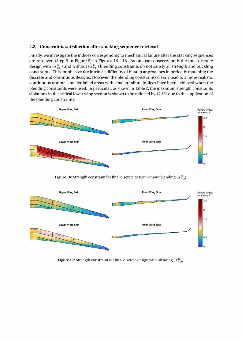
4.3 Constraints satisfaction after stacking sequence retrieval
Finally, we investigate the indices corresponding to mechanical failure after the stacking sequencesare retrieved (Step 5 in Figure 5) in Figures 16 - 18. As one can observe, both the final discretedesign with (X B
F D ) and without (X UF D ) blending constraints do not satisfy all strength and buckling
constraints. This emphasize the intrinsic difficulty of bi-step approaches in perfectly matching thediscrete and continuous designs. However, the blending constraints clearly lead to a more realisticcontinuous optima, smaller failed areas with smaller failure indices have been achieved when theblending constraints were used. In particular, as shown in Table 2, the maximum strength constraintsviolations in the critical lower wing section is shown to be reduced by 47.1% due to the application ofthe blending constraints.
Upper Wing Skin
Lower Wing Skin
Front Wing Spar
Rear Wing Spar
0 5 10 15-1
0
1
2
3Rear Wing Spar
0
0.5
1
1.5
2
2.5
Failure Indexfor strength
Figure 16: Strength constraint for final discrete design without blending (X UF D ).
Upper Wing Skin
Lower Wing Skin
Front Wing Spar
Rear Wing Spar
0 5 10 15-1
0
1
2
3Rear Wing Spar
0
0.5
1
1.5
2
2.5
Failure Indexfor strength
Figure 17: Strength constraint for final discrete design with blending (X BF D ).

Upper Wing Skin without Blending Upper Wing Skin with Blending
Upper Wing Skin with Blending
0
0.5
1
1.5
2
Failure Indexfor buckling
Figure 18: Buckling constraint in the upper wing skins for the final discrete design without (X UF D ) and with
blending (X BF D ).
Table 2: Maximum failure index for the retrieved stacking sequence.
Strength BucklingWithout blending constraints 2.595 1.922
With blending constraints 1.373 1.572Reduction in maximum failure index 47.1% 18.2%violation due to blending constraints
5 Conclusion
Locally optimized composite structures are likely to lead to optimum designs that are affected bystructural discontinuities between adjacent regions. One possibility to minimize those discontinuitiesand to ensure structural integrity is to enforce ply continuity (i.e. blending) during the optimizationthroughout the whole structure. Several bi-step strategies, relying on a continuous gradient-basedoptimization of lamination parameters followed by a discrete stacking sequence optimization stepduring which blending is enforced, have been successfully used to retrieve blended solutions. However,due to the discrepancies between the two design spaces, significant differences could be observedbetween the continuous and discrete designs.
In the present paper a set of continuous blending constraints, recently proposed by the authors,have been applied to a bi-step approach during the aeroelastic optimization of a variable stiffnesswing. Both in-plane and out-of-plane composite stiffness matrices have been optimized via lam-ination parameters with respect to strength (based on strain) and local buckling constraints. Thecontinuous blending constraints have significantly reduced the discrepancies between the continuousand discrete optimum (−59.2%) by modifying the thickness distribution over the wingspan and bysmoothing the change in stiffness distribution and orientation. As a result, the retrieved blendedstacking sequences match more closely the continuous design a the price of at slightly heavier design(+2.2%).
Constraints satisfaction, of the retrieved stacking sequence obtained with and without the contin-uous blending constraints, have shown a reduction of failed elements and sections when blendingconstraints have been used. Moreover, failure indices violation resulted in up to 47.1% reductionwhen the blending constraints have been used. Although both discrete designs presented failureindices violations, due to the intrinsic discrepancies between the continuous and discrete designspace, these results demonstrate that more realistic continuous designs can be obtained with thecontinuous blending constraints.

6 Acknowledgements
The research leading to these results has received funding from the European Union Seventh Frame-work Programme FP7-PEOPLE-2012-ITN under grant agreement n◦ 316394, Aerospace Multidisciplinarity-Enabling DEsign Optimization (AMEDEO) Marie Curie Initial Training Network.
References
[1] Dillinger, J. K. S., Static Aeroelastic Optimization of Compisite Wing with Variable Stiffness Lami-nates, Ph.D. thesis, Delft University of Technology, 2014.
[2] IJsselmuiden, S. T., Abdalla, M. M., Seresta, O., and GÃijrdal, Z., “Multi-step blended stackingsequence design of panel assemblies with buckling constraints,” Composites Part B: Engineering,Vol. 40, No. 4, 2009, pp. 329 – 336.
[3] Adams, D. B., Watson, L. T., GÃijrdal, Z., and Anderson-Coo, C. M., “Genetic algorithm optimiza-tion and blending of composite laminates by locally reducing laminate thickness,” Advances inEngineering Software, Vol. 35(1):35-43, 2004.
[4] Campen, J. V., Seresta, O., Abdalla, M. M., and Gurdal, Z., “General blending definitions forstacking sequence design of composite laminate structure,” 49th AIAA/ASME/ASCE/AHS/ASCstructures, structural dynamics, and materials, 2008, pp. 7–10.
[5] Irisarri, F.-X., Lasseigne, A., Leroy, F.-H., and Riche, R. L., “Optimal design of laminated compositestructures with ply drops using stacking sequence tables,” Composite Structures, Vol. 107, 2014,pp. 559 – 569.
[6] Peeters, D. M., Hesse, S., and Abdalla, M. M., “Stacking sequence optimisation of variable stiffnesslaminates with manufacturing constraints,” Composite Structures, Vol. 125, 2015, pp. 596 – 604.
[7] Dillinger, J. K. S., Klimmek, T., Abdalla, M. M., and Gurdal, Z., “Stiffness Optimization of Compos-ite Wings with Aeroelastic Constraints,” Journal of Aircraft, Vol. 50, No. 4, 2013, pp. 1159–1168.
[8] Liu, D., Toropov, V. V., Querin, O. M., and Barton, D. C., “Bilevel Optimization of Blended Compos-ite Wing Panels,” Journal of Aircraft, Vol. 48, No. 1, 2011.
[9] Macquart, T., Bordogna, M. T., Lancelot, P., and Breuker, R. D., “Derivation and application ofblending constraints in lamination parameter space for composite optimisation,” CompositeStructures, Vol. 135, 2016, pp. 224 – 235.
[10] Soremekun, G., GÃijrdal, Z., Kassapoglou, C., and Toni, D., “Stacking sequence blending ofmultiple composite laminates using genetic algorithms,” Composite Structures, Vol. 56, No. 1,2002, pp. 53 – 62.
[11] Macquart, T., Werter, N., and Breuker, R. D., “Aeroelastic Tailoring of Blended Composite Struc-tures using Lamination Parameters,” 57th AIAA/ASCE/AHS/ASC Structures, Structural Dynamics,and Materials Conference, AIAA SciTech, 2016.
[12] Tsai, S. W. and Hahn, H. T., Introduction to composite materials, Technomic Publishing Co, 1980.

[13] COMPOSITE MATERIALS HANDBOOK VOLUME 3. POLYMER MATRIX COMPOSITES MATERIALSUSAGE, DESIGN, AND ANALYSIS, 2002.
[14] Optibless - an open-source toolbox for the optimisation of blended stacking sequences (accepted).In The seventeenth European Conference on Composite Materials (ECCM17), 2016.
[15] Fukunaga, H. and Sekine, H., “Stiffness design method of symmetric laminates using laminationparameters,” AIAA Journal, Vol. 30, No. 11, 1992, pp. 2791–2793.
[16] Raju, G., Wu, Z., and Weaver, P., “On Further Developments of Feasible Region of LaminationParameters for Symmetric Composite Laminates,” 55th AIAA/ASME/ASCE/AHS/ASC Structures,Structural Dynamics, and Materials Conference, AIAA SciTech, (AIAA 2014-1374), 2014.
[17] Ijsselmuiden, S. T., Abdalla, M. M., and GÃijrdal, Z., “Implementation of Strength-Based FailureCriteria in the Lamination Parameter Design Space,” AIAA Journal, Vol. 46, No. 7, 2008, pp. 1826–1834.