Deformations meter and recorder
2
DEFORMATIONS METER AND RECORDER O. N. Fofanov and Yu. F. Gerasimov UDC 620.172.2.087 This instrument is used for measuring creepage in metal specimens. It consists of the following basic units (see Fig. 1), comprising input transducer I, mismatch transducer II, amplifier III, servomotor IV, selsyntransmissions V, decade counters VI, and diagram-plotting device VII. The deformations of spechnen 1 are measured across base l. Quartz rods 2 are then displaced with respect to quartz rods 3 by the amount of the deformation. These quartz rods serve to transmit the deformation from the working chamber of the furnace to the input transducer I which is outside the furnace. Casing 4 of the input transducer rests with its supports on rods 2 and is connected by means of hinged bearing 5 to the test machine. The instrument's middle part 6 carries an elastic cantilever 7 with a connect- ing pipe and measuring nozzle 8. This nozzle can be displaced with respect to strip 9 by means of screw 10 which bends cantilever 7. In addition, the nozzle can be displaced by rotating the instrument's middle part 6 with re- spect to casing 4 by means of screw 11. Chamber 12 of the mismatch transducer II is fed with air under stabilized pressure (in the range of 5-8 kN/m~). The air is then transmitted through input nozzles 13 and 14 to chambers 15, 15a, and 16, 16a which are separated by diaphragm 17. The pressure in chambers 15 and 15a depends on gap 6 be- tween nozzle 8 and the surface of strip 9, whereas the pressure in chambers 16 and 16a depends on the slot set by means of screw 18. The difference of pressures in chambers 15a and 16a is impressed on diaphragm 17, thus bending elastic plate 19 together with mirror 20 which is glued to it. The luminous beam from lamp 21 is reflected by mirror 20 and intermediate mirrors 21 onto photovaristors 23 and 24. The illuminance ratio of the photovaristors depends on the 18 Z8 ~',,3 3 8 JJ ]2 3~ gT Fig. 1 Translated from Izmeritel'naya Tekhnika, No. 10, pp. 89-90, October, 1967. Original article submitted November 22, 1965. 1285
-
Upload
o-n-fofanov -
Category
Documents
-
view
223 -
download
2
Transcript of Deformations meter and recorder

D E F O R M A T I O N S M E T E R AND R E C O R D E R
O. N. F o f a n o v a n d Y u . F . G e r a s i m o v UDC 620.172.2.087
This instrument is used for measuring creepage in meta l specimens. It consists of the following basic units (see Fig. 1), comprising input transducer I, mismatch transducer II, ampl i f ier III, servomotor IV, selsyntransmissions V, decade counters VI, and d iagram-p lo t t ing device VII. The deformations of spechnen 1 are measured across base l . Quartz rods 2 are then displaced with respect to quartz rods 3 by the amount of the deformation. These quartz rods serve to transmit the deformation from the working chamber of the furnace to the input transducer I which is outside the furnace. Casing 4 of the input transducer rests with its supports on rods 2 and is connected by means of hinged bearing 5 to the test machine. The instrument's middle part 6 carries an e las t ic cant i lever 7 with a connect- ing pipe and measuring nozzle 8. This nozzle can be displaced with respect to strip 9 by means of screw 10 which
bends cant i lever 7. In addition, the nozzle can be displaced by rota t ing the instrument 's middle part 6 with re- spect to casing 4 by means of screw 11. Chamber 12 of the mismatch transducer II is fed with air under s tabi l ized pressure (in the range of 5-8 kN/m~). The air is then transmitted through input nozzles 13 and 14 to chambers 15,
15a, and 16, 16a which are separated by diaphragm 17. The pressure in chambers 15 and 15a depends on gap 6 be - tween nozzle 8 and the surface of strip 9, whereas the pressure in chambers 16 and 16a depends on the slot set by means of screw 18.
The difference of pressures in chambers 15a and 16a is impressed on diaphragm 17, thus bending elas t ic p la te 19 together with mirror 20 which is glued to it. The luminous beam from lamp 21 is ref lected by mirror 20 and in termediate mirrors 21 onto photovaristors 23 and 24. The i l luminance ratio of the photovaristors depends on the
18
Z8
~',,3 3
8 JJ
]2 3~
gT
Fig. 1
Translated from Izmer i t e l ' naya Tekhnika, No. 10, pp. 89-90, October, 1967. Original ar t ic le submitted
November 22, 1965.
1285
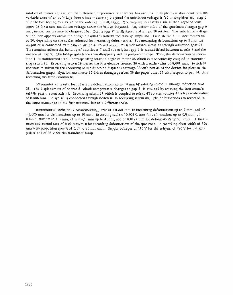
rotation of mirror 20, i.e., on the difference of pressures in chamber 15a and 16a. The photovaristors constitute the variable arms of an ac bridge from whose measuring diagonal the unbalance voltage is fed to amplifier III. Gap 6 is set before testing to a value of the order of 0.06-0.1 ram. The pressure in chamber 16a is then adjusted with screw 18 for a zero unbalance voltage across the bridge d iagonal Any deformation of the specimen changes gap 6 and, hence, the pressure in chamber 15a. Diaphragm 17 is displaced and mirror 20 rotates. The unbalance voltage
which then appears across the bridge diagonal is transmitted through amplifier Ill and switch 40 to servomotors 95 or 26, depending on the scales selected for measuring deformations. For measuring deformations up to 2 mm the amplifier is connected by means of switch 40 to servomotor 26 which rotates screw 10 through reduction gear 27. This rotation adjusts the bending of cantilever 7 unt i l the original gap 6 is reestablished between nozzle 8 and the surface of strip 9. The bridge unbalance then disappears and theservomotor stops. Thus, the deformation of speci-
men 1 is transformed into a corresponding rotation angle of motor 26 which is mechanical ly coupled to transmit- ting selsyn 28. Receiving selsyn 29 rotates the four-decade counter 30 with a scale value of 0.001 mm. Switch 31 connects to setsyn 28 the receiving selsyn 32 which displaces carriage aa with pen 34 of the device for plotting the deformation graph. Synchronous motor 35 drives through gearbox 36 the paper chart 37 with respect to pen 34, thus recording the t ime coordinate.
Servomotor 25 is used for measuring deformations up to 10 mm by rotating screw 11 through reduction gear
38. The displacement of nozzle 8, which compensates changes in gap 6, is attained by rotating the instrument's middle part 6 about axis 39. Receiving selsyn 41 which is coupled to selsyn 42 rotates counter 43 with a scale value
of 0.005 ram. Selsyn 42 is connected through switch 31 to receiving selsyn 32. The deformations are recorded in
the same manner as in the first instance, but to a different scale.
Instrument's Technical Characteristics. Error of i 0.001 mm in measuring deformations up to 2 mm, and of 0.005 mm for deformations up to 10 ram. Recording scale of 0.001/1 mm for deformations up to 0.8 mm, of
0.002/1 mm up to 1.6 mm, of 0.005/1 mm up to 4 mm, and of 0.01/1 mm for deformations up to 8 ram. A maxi -
mum undistorted rate of 0.09 m m / m i n for recording deformations of the specimen. A recording chart width of 800 mm with propulsion speeds of 0.01 to 80 m m / m i n . Supply vokages of 110 V for the selsyns, of 220 V for the am- plifier and of 36 V for the transducer lamp.
1286


![LOCAL DEFORMATIONS OF WILD GROUP ACTIONS · Wiles, Taylor-Wiles, and others ([26], [25]). M. Artin and others have studied deformations of singularities. We focus on deformations](https://static.fdocuments.net/doc/165x107/5f0c14bc7e708231d433a5f8/local-deformations-of-wild-group-actions-wiles-taylor-wiles-and-others-26.jpg)