Deformation of Single Crystals - UPRMacademic.uprm.edu/pcaceres/Courses/MechMet/MET-3A.pdf ·...
52
Deformation of Single Crystals When a single crystal is deformed under a tensile stress, it is observed that plastic deformation occurs by slip on well‐defined parallel crystal planes. Sections of the crystal slide relative to one another, changing the geometry of the sample as shown in the diagram. Slip always occurs on a particular set of crystallographic planes, known as slip planes. Slip always takes place along a consistent set of directions within these planes – these are called slip directions. The combination of slip plane and slip direction together makes up a slip system slip system.
Transcript of Deformation of Single Crystals - UPRMacademic.uprm.edu/pcaceres/Courses/MechMet/MET-3A.pdf ·...
Deformation of Single CrystalsWhen a single crystal is deformed under a tensile stress, it is observed that plastic deformation occurs by slip on well‐defined parallel crystal planes. Sections of the crystal slide relative to one another, changing the geometry of the sample as shown in the diagram.
Slip always occurs on a particular set of crystallographic planes, known as slip planes. Slip always takes place along a consistent set of directions within these planes – these are called slip directions. The combination of slip plane and slip direction together makes up a slip systemslip system.
Slip systems are usually specified using the Miller index notation. For example, cubic close‐packed metals slip on
The slip direction must lie in the slip plane.
{ }1 1 10 11
Slip occurs by dislocation motion. To move dislocations, a certain stress must be applied to overcome the resistance to dislocation motion.
Slip occurs when the shear stress acting in the slip direction on the slip plane reaches some critical value. This critical shear stress is related to the stress required to move dislocations across the slip plane.
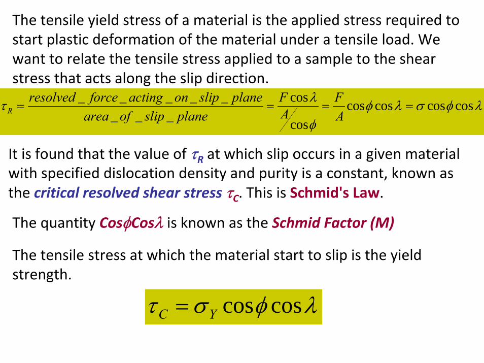
The tensile yield stress of a material is the applied stress required to start plastic deformation of the material under a tensile load. We want to relate the tensile stress applied to a sample to the shear stress that acts along the slip direction.
λφσλφφ
λτ coscoscoscoscos
cos___
_____====
AF
AF
planeslipofareaplanesliponactingforceresolved
R
It is found that the value of τR at which slip occurs in a given material with specified dislocation density and purity is a constant, known as the critical resolved shear stress τC. This is Schmid's Law.
The quantity CosφCosλ is known as the Schmid Factor (M)
The tensile stress at which the material start to slip is the yield strength.
λφστ coscosYC =
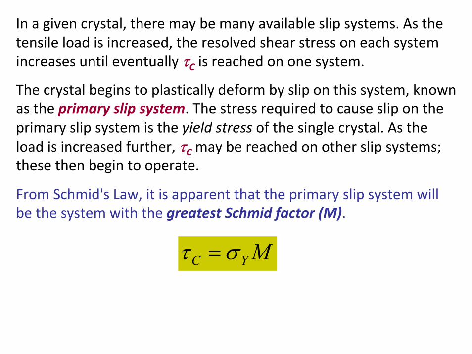
In a given crystal, there may be many available slip systems. As the tensile load is increased, the resolved shear stress on each system increases until eventually τC is reached on one system.
The crystal begins to plastically deform by slip on this system, known as the primary slip system. The stress required to cause slip on the primary slip system is the yield stress of the single crystal. As the load is increased further, τC may be reached on other slip systems; these then begin to operate.
From Schmid's Law, it is apparent that the primary slip system will be the system with the greatest Schmid factor (M).
MYC στ =
Experimental measurements showed that
At RT the major source for plastic deformation is the dislocation motion through the crystal lattice.
Dislocation motions occurs on fixed crystal planes (“slip planes”) in fixed crystallographic directions (corresponding to the Burgers vector of the dislocation that carries the slip)
The crystal structure of metals is not altered by the plastic flow Volume changes during plastic flow are negligible
Basic ConsiderationsBasic ConsiderationsExperimental technique
Uniaxial Tension or Compression
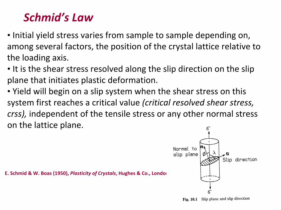
Schmid’s Law• Initial yield stress varies from sample to sample depending on, among several factors, the position of the crystal lattice relative to the loading axis.• It is the shear stress resolved along the slip direction on the slip plane that initiates plastic deformation.• Yield will begin on a slip system when the shear stress on thissystem first reaches a critical value (critical resolved shear stress, crss), independent of the tensile stress or any other normal stress on the lattice plane.
E. Schmid & W. Boas (1950), Plasticity of Crystals, Hughes & Co., London.
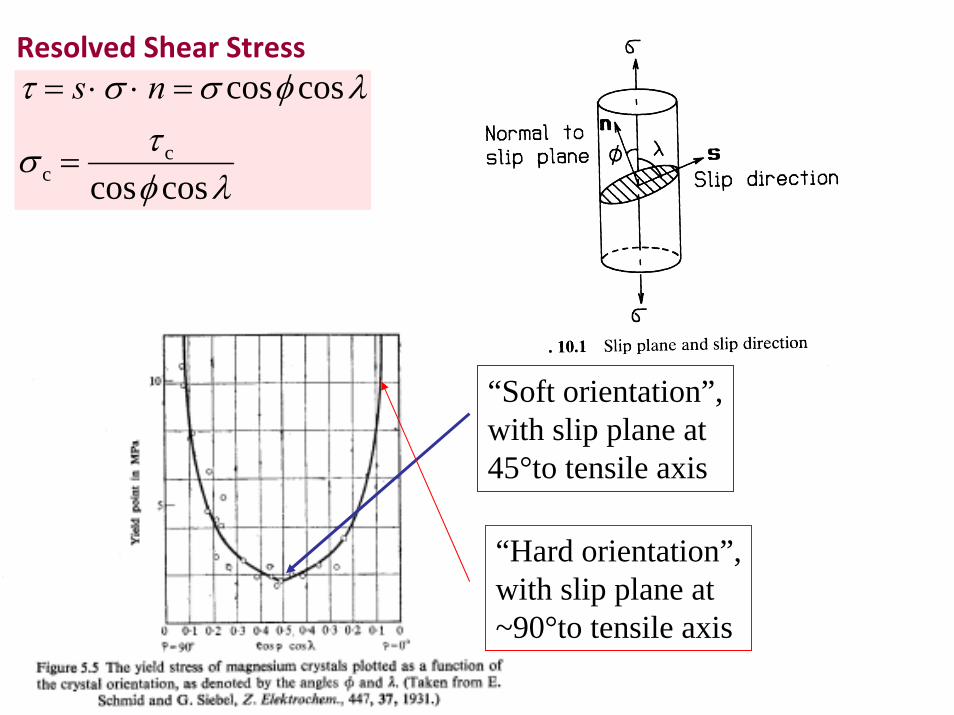
Resolved Shear Stressτ = s ⋅σ ⋅ n =σ cosφ cosλ
σ c =τ c
cosφ cosλ
“Soft orientation”,with slip plane at45°to tensile axis
“Hard orientation”,with slip plane at~90°to tensile axis
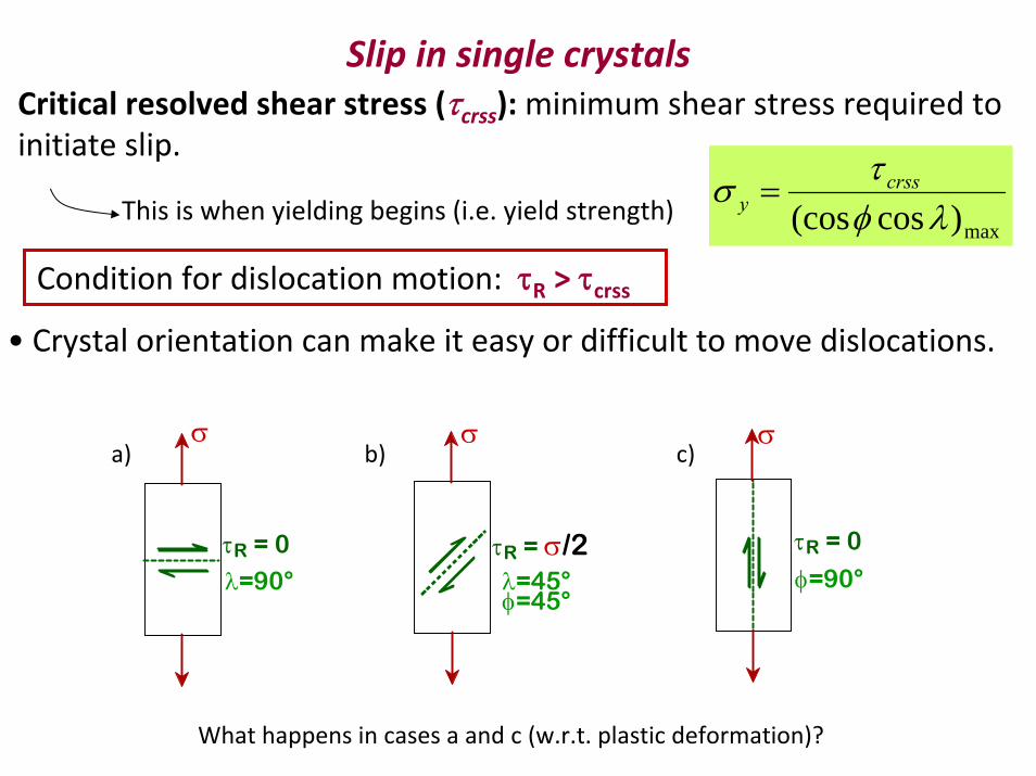
Slip in single crystalsCritical resolved shear stress (τcrss): minimum shear stress required to initiate slip.
This is when yielding begins (i.e. yield strength)
Condition for dislocation motion: τR > τcrss
max)cos(cos λφτσ crss
y =
• Crystal orientation can make it easy or difficult to move dislocations.
τR = 0
φ=90°
σ
τR = σ/2λ=45°φ=45°
σ
τR = 0
λ=90°
σa)
What happens in cases a and c (w.r.t. plastic deformation)?
b) c)
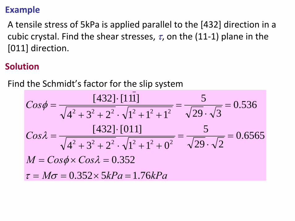
Example
A tensile stress of 5kPa is applied parallel to the [432] direction in a cubic crystal. Find the shear stresses, τ, on the (11‐1) plane in the [011] direction.
Solution
Find the Schmidt’s factor for the slip system
kPakPaMCosCosM
Cos
Cos
76.15352.0352.0
6565.0229
5011234
]011[]432[
536.0329
5111234
]111[]432[
222222
222222
=×===×=
=⋅
=++⋅++
⋅=
=⋅
=++⋅++
⋅=
στλφ
λ
φ
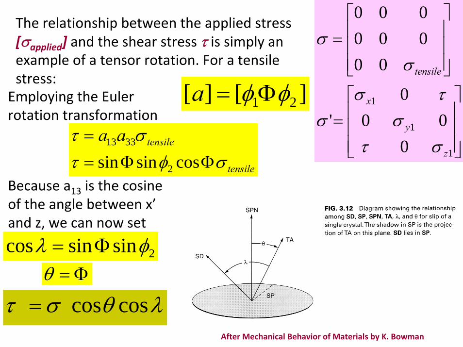
The relationship between the applied stress [σapplied] and the shear stress τ is simply an example of a tensor rotation. For a tensile stress:
⎥⎥⎥
⎦
⎤
⎢⎢⎢
⎣
⎡=
⎥⎥⎥
⎦
⎤
⎢⎢⎢
⎣
⎡=
1
1
1
000
0'
00000000
z
y
x
tensile
στσ
τσσ
σσ
Employing the Euler rotation transformation
][][ 21 φφ Φ=a
tensile
tensileaaσφτ
στΦΦ=
=cossinsin 2
3313
Because a13 is the cosine of the angle between x’and z, we can now set
After Mechanical Behavior of Materials by K. Bowman
2sinsincos φλ Φ=Φ=θ
λθστ coscos=
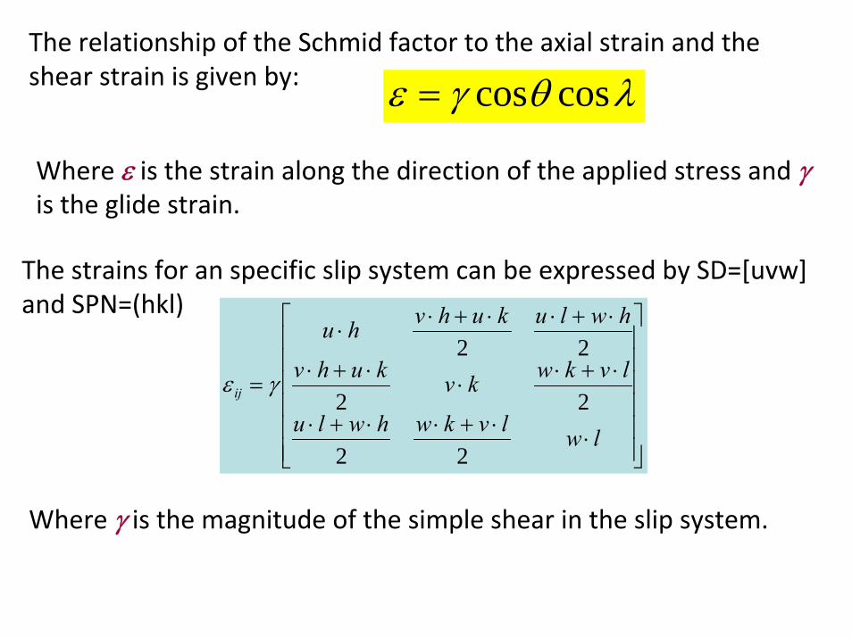
The relationship of the Schmid factor to the axial strain and the shear strain is given by: λθγε coscos=
Where ε is the strain along the direction of the applied stress and γis the glide strain.
The strains for an specific slip system can be expressed by SD=[uvw] and SPN=(hkl)
⎥⎥⎥⎥⎥⎥
⎦
⎤
⎢⎢⎢⎢⎢⎢
⎣
⎡
⋅⋅+⋅⋅+⋅
⋅+⋅⋅
⋅+⋅
⋅+⋅⋅+⋅⋅
=
lwlvkwhwlu
lvkwkvkuhv
hwlukuhvhu
ij
22
22
22γε
Where γ is the magnitude of the simple shear in the slip system.
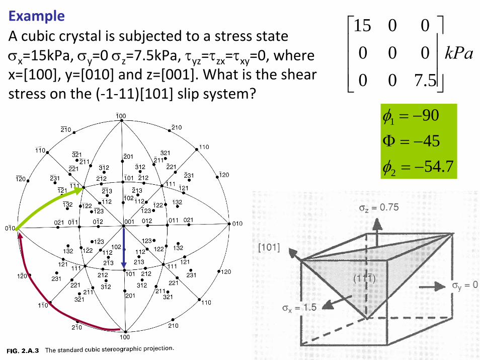
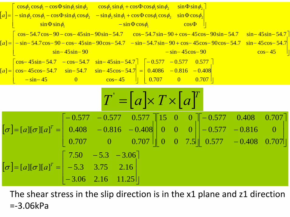
ExampleA cubic crystal is subjected to a stress state σx=15kPa, σy=0 σz=7.5kPa, τyz=τzx=τxy=0, where x=[100], y=[010] and z=[001]. What is the shear stress on the (‐1‐11)[101] slip system?
7.544590
2
1
−=−=Φ−=
φ
φ
kPa⎥⎥⎥
⎦
⎤
⎢⎢⎢
⎣
⎡
5.7000000015
[ ]
[ ]⎥⎥⎥
⎦
⎤
⎢⎢⎢
⎣
⎡
−−
−−==
⎥⎥⎥
⎦
⎤
⎢⎢⎢
⎣
⎡
−−−
−
⎥⎥⎥
⎦
⎤
⎢⎢⎢
⎣
⎡
⎥⎥⎥
⎦
⎤
⎢⎢⎢
⎣
⎡−−
−−==
25.1116.206.316.275.33.506.33.550.7
]][][[
707.0408.0577.00816.0577.0707.0408.0577.0
5.7000000015
707.00707.0408.0816.0408.0
577.0577.0577.0]][][[
T
T
aa
aa
σσ
σσ
[ ]
⎥⎥⎥
⎦
⎤
⎢⎢⎢
⎣
⎡−−
−−=
⎥⎥⎥
⎦
⎤
⎢⎢⎢
⎣
⎡
−−−−−−−−−−−−−−
=
⎥⎥⎥
⎦
⎤
⎢⎢⎢
⎣
⎡
−−−−−−−−−−−+−−−−−−−−−−−−−−−+−−−−−−−−
=
⎥⎥⎥
⎦
⎤
⎢⎢⎢
⎣
⎡
ΦΦ−ΦΦΦ+−Φ−−ΦΦ+Φ−
=
707.00707.0408.0816.04086.0
577.0577.0577.0
45cos045sin7.54cos45sin7.54sin7.54cos45cos7.54sin45sin7.54cos7.54sin45cos
][
45cos90cos45sin90sin45sin7.54cos45sin7.54cos90cos45cos90sin7.54sin7.54cos90sin45cos90cos7.54sin7.54sin45sin7.54sin90cos45cos90sin7.54cos7.54sin90sin45cos90cos7.54cos
][
coscossinsinsincossincoscoscossinsincossincoscossinsinsinsincoscossincossinsincoscoscos
11
221122112
221122112
a
a
aφφ
φφφφφφφφφφφφφφφφφφ
The shear stress in the slip direction is in the x1 plane and z1 direction =‐3.06kPa
[ ] [ ]TaTaT ××='
Example:
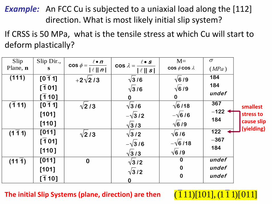
If CRSS is 50 MPa, what is the tensile stress at which Cu will start to deform plastically?
smalleststress tocause slip(yielding)
The initial Slip Systems (plane, direction) are then (1 11)[101], (1 1 1)[011]
Slip Plane, n
Slip Dir., s
cos φ =•n
| || n |
cos λ =
• s| || s |
M= cos φ cos λ )(MPa
σ
(111)
[0 1 1]
[ 1 01]
[ 1 10]
+2 2 / 3
3 / 6
3 / 6
0
6 / 9
6 / 9
0
184
184
undef
( 1 11)
[0 1 1]
[101]
[110 ]
2 / 3
3 / 6
− 3 / 2
3 / 3
6 /18
− 6 / 6
6 / 9
367
−122
184
(1 1 1)
[011]
[ 1 01]
[110 ]
2 / 3
3 / 2
− 3 / 6
3 / 3
6 / 6
− 6 /18
6 / 9
122
−367
184
(11 1 )
[011]
[101]
[ 1 10]
0
3 / 2
3 / 2
0
0
0
0
undefundefundef
An FCC Cu is subjected to a uniaxial load along the [112] direction. What is most likely initial slip system?
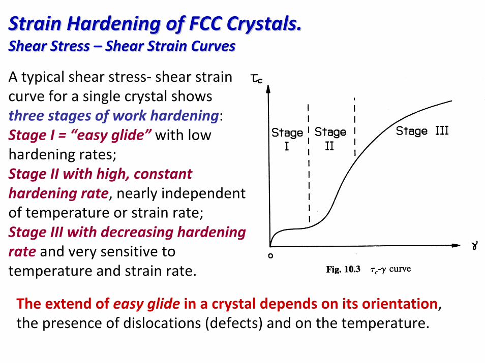
Strain Hardening of FCC Crystals.Strain Hardening of FCC Crystals.Shear Stress Shear Stress –– Shear Strain CurvesShear Strain Curves
A typical shear stress‐ shear strain curve for a single crystal shows three stages of work hardening: Stage I = “easy glide” with low hardening rates; Stage II with high, constant hardening rate, nearly independent of temperature or strain rate; Stage III with decreasing hardening rate and very sensitive to temperature and strain rate.
The extend of easy glide in a crystal depends on its orientation, the presence of dislocations (defects) and on the temperature.
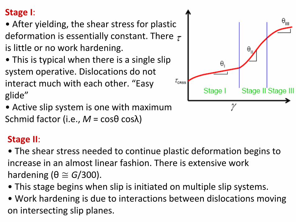
Stage II:• The shear stress needed to continue plastic deformation begins to increase in an almost linear fashion. There is extensive work hardening (θ≅ G/300).• This stage begins when slip is initiated on multiple slip systems.• Work hardening is due to interactions between dislocations moving on intersecting slip planes.
Stage I:• After yielding, the shear stress for plastic deformation is essentially constant. There is little or no work hardening.• This is typical when there is a single slip system operative. Dislocations do not interact much with each other. “Easy glide”• Active slip system is one with maximum Schmid factor (i.e., M = cosθ cosλ)
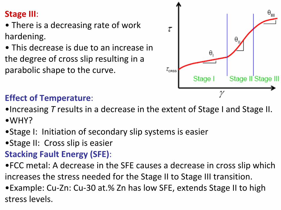
Stage III:• There is a decreasing rate of work hardening.• This decrease is due to an increase in the degree of cross slip resulting in a parabolic shape to the curve.
Effect of Temperature:•Increasing T results in a decrease in the extent of Stage I and Stage II.•WHY?•Stage I: Initiation of secondary slip systems is easier•Stage II: Cross slip is easierStacking Fault Energy (SFE):•FCC metal: A decrease in the SFE causes a decrease in cross slip which increases the stress needed for the Stage II to Stage III transition.•Example: Cu‐Zn: Cu‐30 at.% Zn has low SFE, extends Stage II to high stress levels.
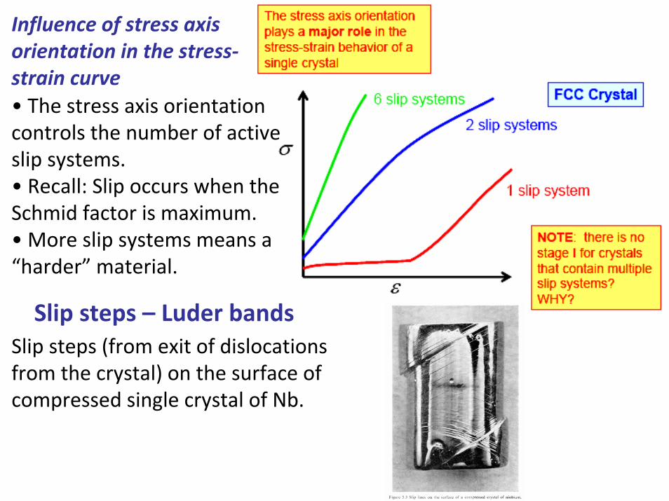
Influence of stress axis orientation in the stress‐strain curve• The stress axis orientation controls the number of active slip systems.• Recall: Slip occurs when the Schmid factor is maximum.• More slip systems means a “harder” material.
Slip steps – Luder bandsSlip steps (from exit of dislocations from the crystal) on the surface of compressed single crystal of Nb.
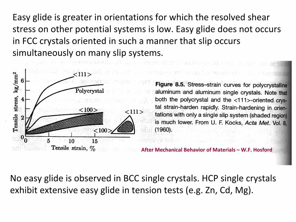
Easy glide is greater in orientations for which the resolved shear stress on other potential systems is low. Easy glide does not occurs in FCC crystals oriented in such a manner that slip occurs simultaneously on many slip systems.
No easy glide is observed in BCC single crystals. HCP single crystals exhibit extensive easy glide in tension tests (e.g. Zn, Cd, Mg).
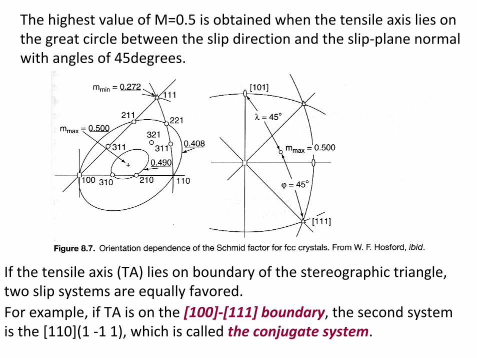
After Mechanical Behavior of Materials – W.F. Hosford
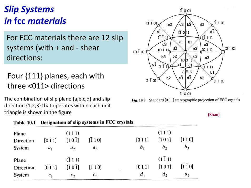
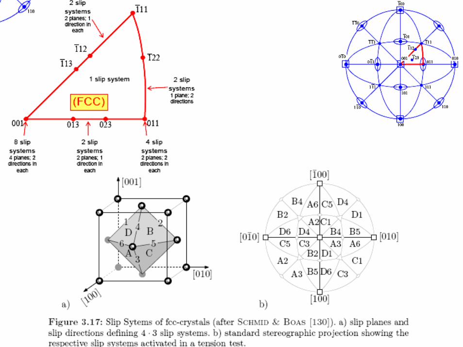
Slip Systems in fccmaterials
For FCC materials there are 12 slip systems (with + and ‐ shear directions:
Four {111} planes, each withthree <011> directions
[Khan]
The combination of slip plane {a,b,c,d} and slip direction {1,2,3} that operates within each unit triangle is shown in the figure

Tensile Deformation of FCC CrystalsFor all orientations of FCC crystals within this stereographic triangle, the Schmid Factor (M) for slip in the [101] direction on the (11‐1) plane is higher than that for any other slip system.The slip system [101](11‐1) is known as the primary slip system.
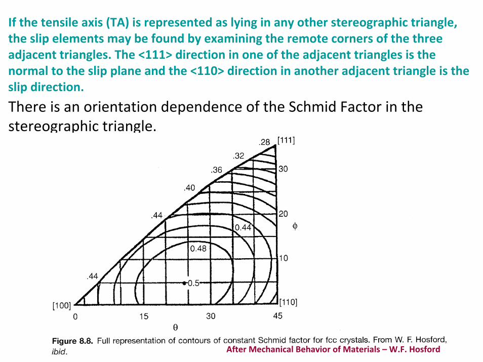
If the tensile axis (TA) is represented as lying in any other stereographic triangle, the slip elements may be found by examining the remote corners of the three adjacent triangles. The <111> direction in one of the adjacent triangles is the normal to the slip plane and the <110> direction in another adjacent triangle is the slip direction.
There is an orientation dependence of the Schmid Factor in the stereographic triangle.
After Mechanical Behavior of Materials – W.F. Hosford
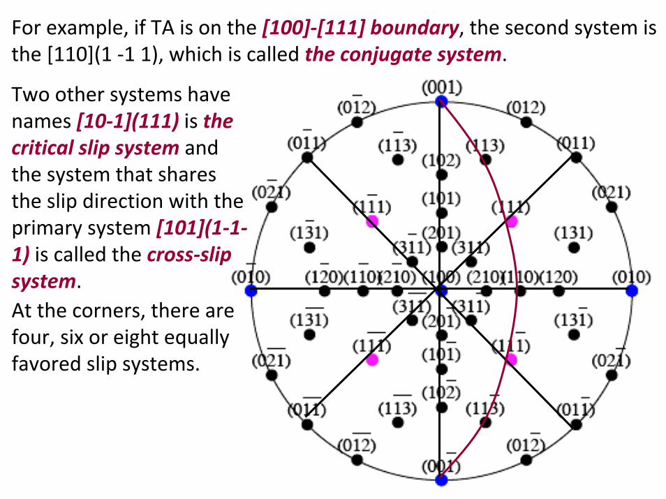
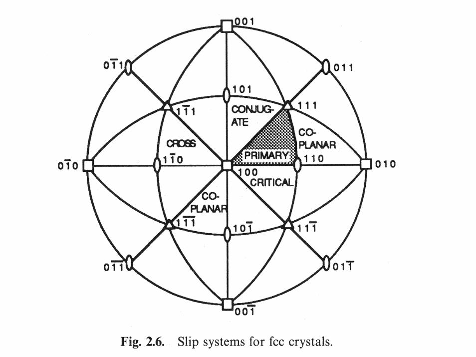
If the tensile axis (TA) lies on boundary of the stereographic triangle, two slip systems are equally favored. For example, if TA is on the [100]‐[111] boundary, the second system is the [110](1 ‐1 1), which is called the conjugate system.
The highest value of M=0.5 is obtained when the tensile axis lies on the great circle between the slip direction and the slip‐plane normal with angles of 45degrees.
For example, if TA is on the [100]‐[111] boundary, the second system is the [110](1 ‐1 1), which is called the conjugate system.
Two other systems have names [10‐1](111) is the critical slip system and the system that shares the slip direction with the primary system [101](1‐1‐1) is called the cross‐slip system. At the corners, there are four, six or eight equally favored slip systems.

Tensile Deformation of BCC CrystalsThe slip direction in BCC metals is always in the direction of close packing, <111>, in various slip planes {110}, {123} and {112}. G.I Taylor described the slip in BCC crystals as <111> pencil glide slip. Note that the basic orientation triangle is divided into two regions with different <111> slip direction.
After Mechanical Behavior of Materials by K. Bowman
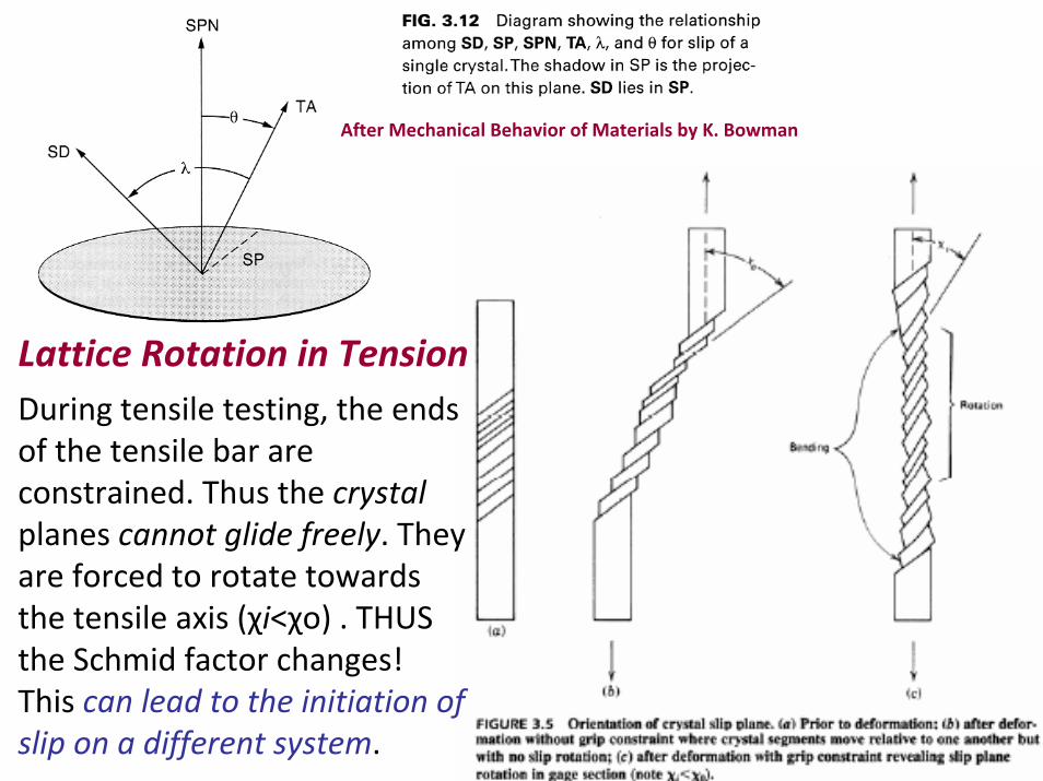
Lattice Rotation in Tension During tensile testing, the ends of the tensile bar are constrained. Thus the crystal planes cannot glide freely. They are forced to rotate towards the tensile axis (χi<χo) . THUS the Schmid factor changes! This can lead to the initiation ofslip on a different system.
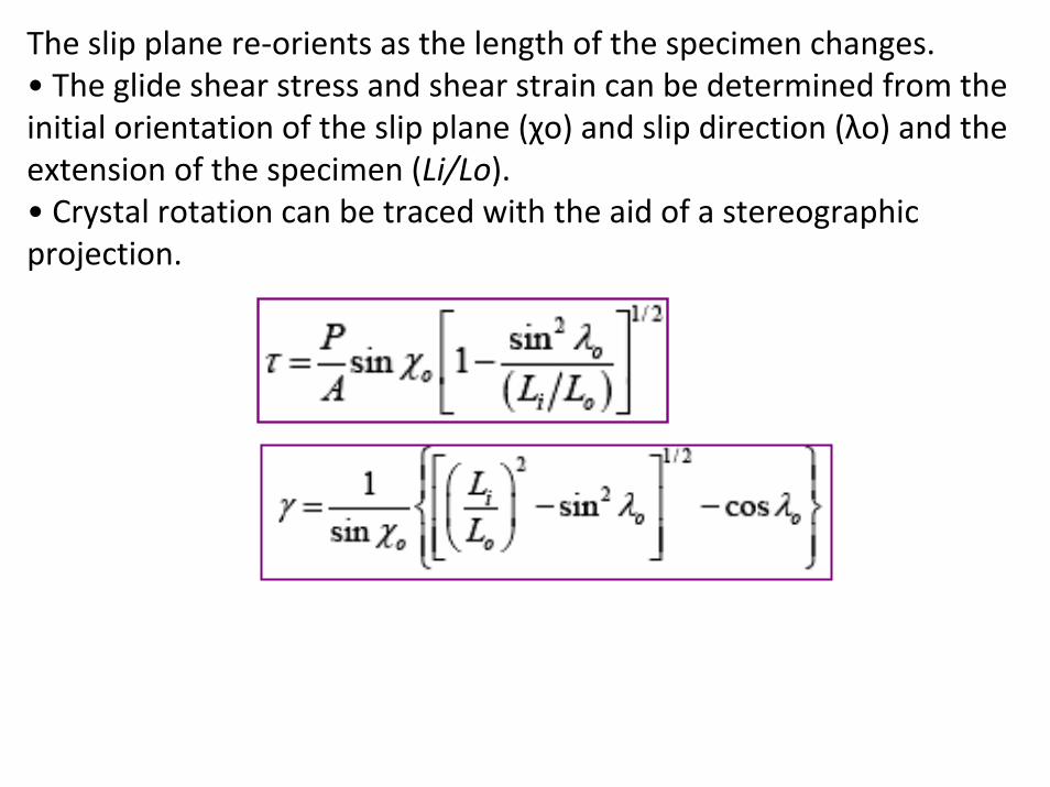
The slip plane re‐orients as the length of the specimen changes.• The glide shear stress and shear strain can be determined from the initial orientation of the slip plane (χo) and slip direction (λo) and the extension of the specimen (Li/Lo).• Crystal rotation can be traced with the aid of a stereographic projection.
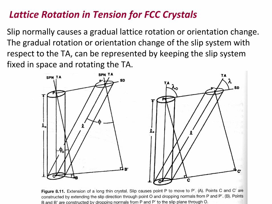
Lattice Rotation in Tension for FCC Crystals
Slip normally causes a gradual lattice rotation or orientation change. The gradual rotation or orientation change of the slip system with respect to the TA, can be represented by keeping the slip systemfixed in space and rotating the TA.
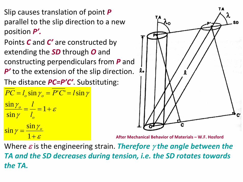
Slip causes translation of point Pparallel to the slip direction to a new position P’.Points C and C’ are constructed by extending the SD through O and constructing perpendiculars from P and P’ to the extension of the slip direction.The distance PC=P’C’. Substituting:
εγγ
εγγ
γγ
+=
+==
===
1sinsin
1sinsin
sin''sin
o
o
o
oo
ll
lCPlPC
After Mechanical Behavior of Materials – W.F. Hosford
Where ε is the engineering strain. Therefore γ the angle between the TA and the SD decreases during tension, i.e. the SD rotates towards the TA.
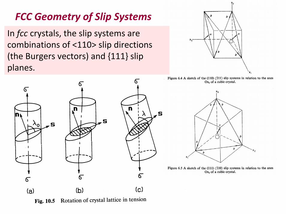
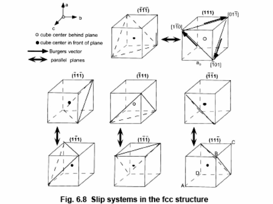
FCC Geometry of Slip Systems
In fcc crystals, the slip systems are combinations of <110> slip directions (the Burgers vectors) and {111} slip planes.
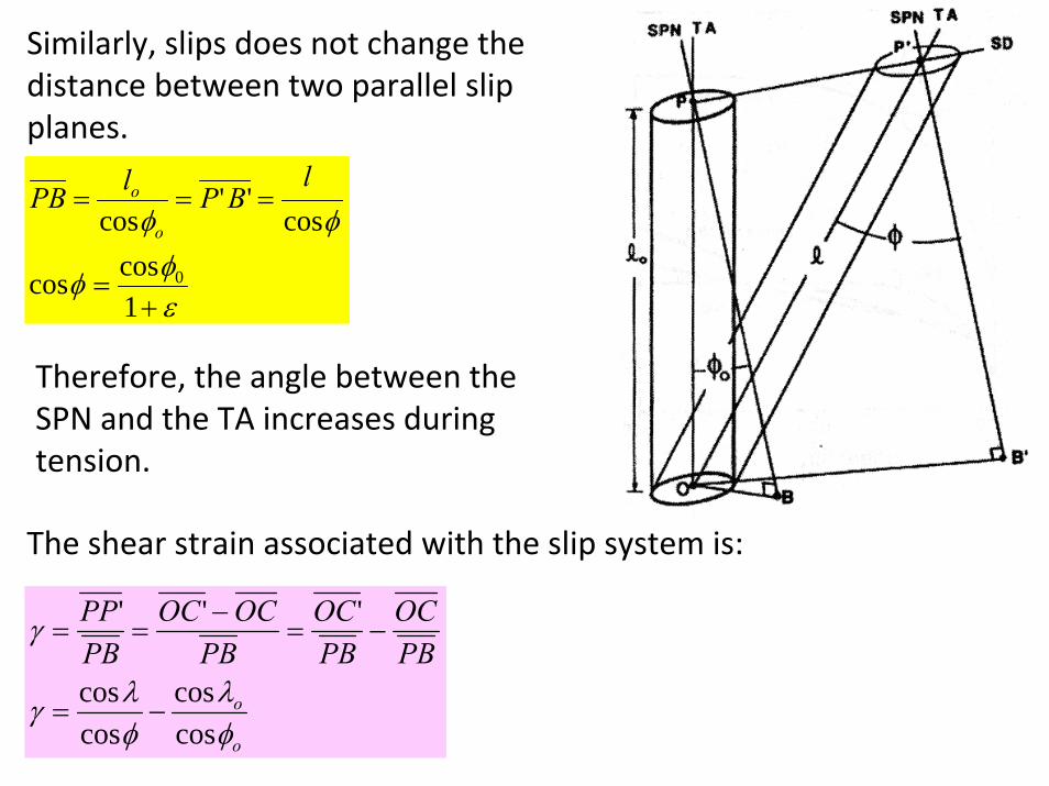
Similarly, slips does not change the distance between two parallel slip planes.
εφφ
φφ
+=
===
1coscos
cos''
cos
0
lBPlPB
o
o
The shear strain associated with the slip system is:
Therefore, the angle between the SPN and the TA increases during tension.
o
o
PBOC
PBOC
PBOCOC
PBPP
φλ
φλγ
γ
coscos
coscos
'''
−=
−=−
==
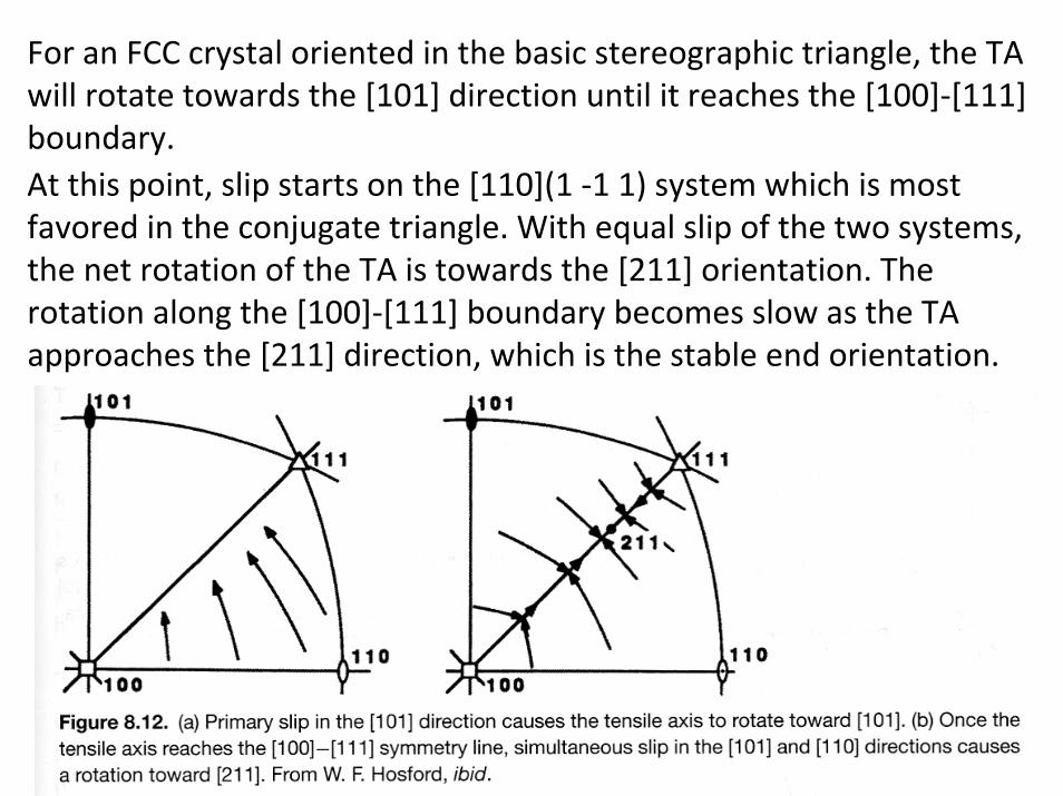
For an FCC crystal oriented in the basic stereographic triangle, the TA will rotate towards the [101] direction until it reaches the [100]‐[111] boundary.At this point, slip starts on the [110](1 ‐1 1) system which is most favored in the conjugate triangle. With equal slip of the two systems, the net rotation of the TA is towards the [211] orientation. Therotation along the [100]‐[111] boundary becomes slow as the TA approaches the [211] direction, which is the stable end orientation.
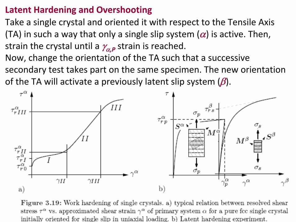
Latent Hardening and OvershootingTake a single crystal and oriented it with respect to the Tensile Axis (TA) in such a way that only a single slip system (α) is active. Then, strain the crystal until a γα,P strain is reached. Now, change the orientation of the TA such that a successive secondary test takes part on the same specimen. The new orientation of the TA will activate a previously latent slip system (β).
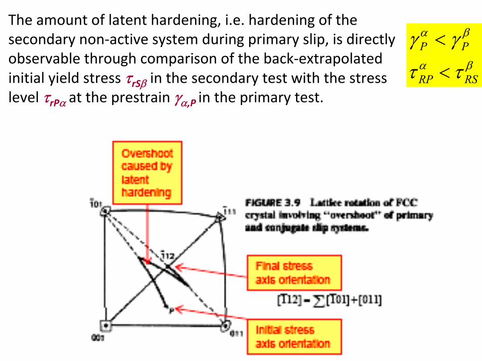
The amount of latent hardening, i.e. hardening of the secondary non‐active system during primary slip, is directly observable through comparison of the back‐extrapolated initial yield stress τrSβ in the secondary test with the stress level τrPα at the prestrain γα,P in the primary test.
βα
βα
ττ
γγ
RSRP
PP
<
<
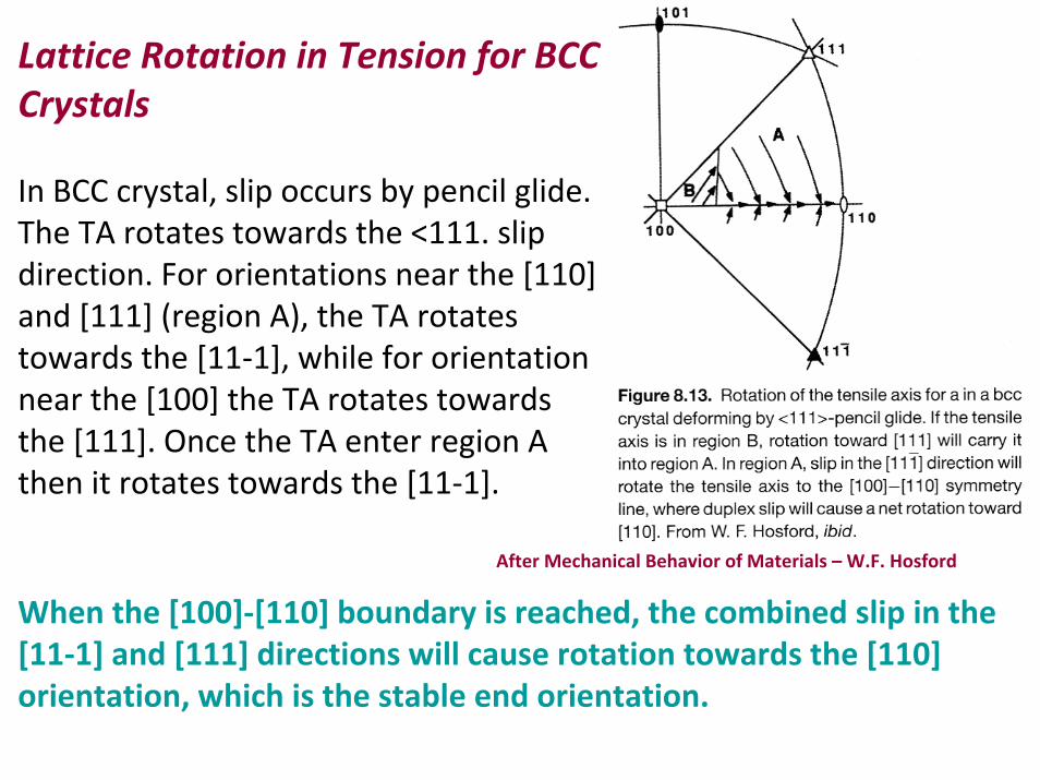
Lattice Rotation in Tension for BCC Crystals
In BCC crystal, slip occurs by pencil glide. The TA rotates towards the <111. slip direction. For orientations near the [110] and [111] (region A), the TA rotates towards the [11‐1], while for orientation near the [100] the TA rotates towards the [111]. Once the TA enter region A then it rotates towards the [11‐1].
After Mechanical Behavior of Materials – W.F. Hosford
When the [100]‐[110] boundary is reached, the combined slip in the [11‐1] and [111] directions will cause rotation towards the [110] orientation, which is the stable end orientation.
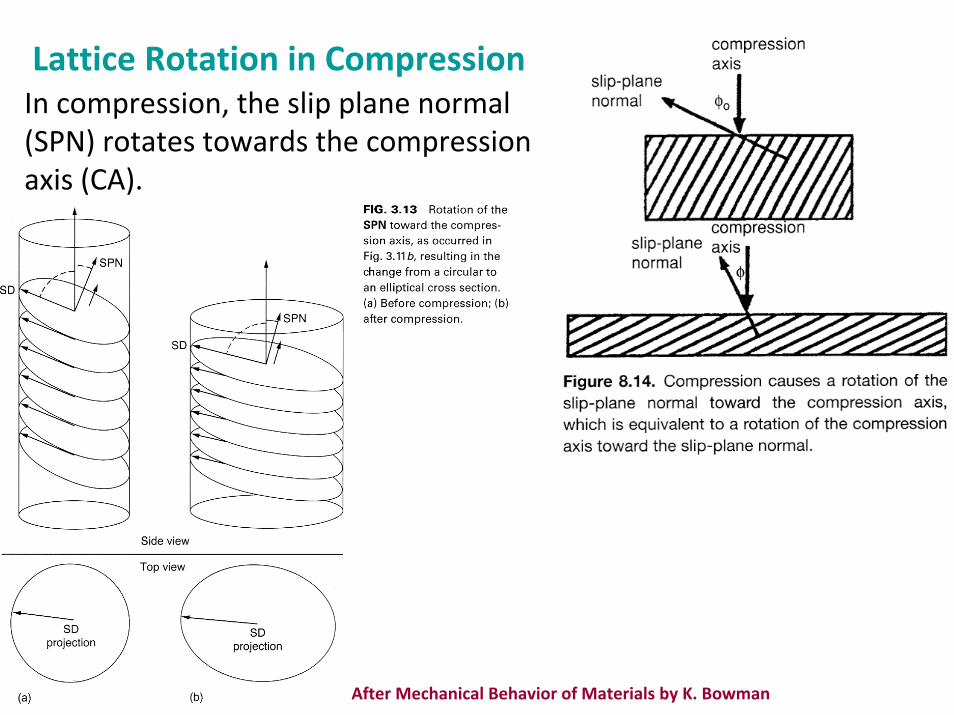
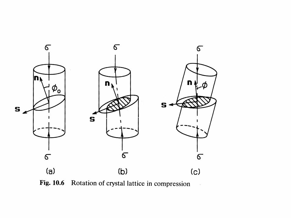
Lattice Rotation in CompressionIn compression, the slip plane normal (SPN) rotates towards the compression axis (CA).
After Mechanical Behavior of Materials by K. Bowman
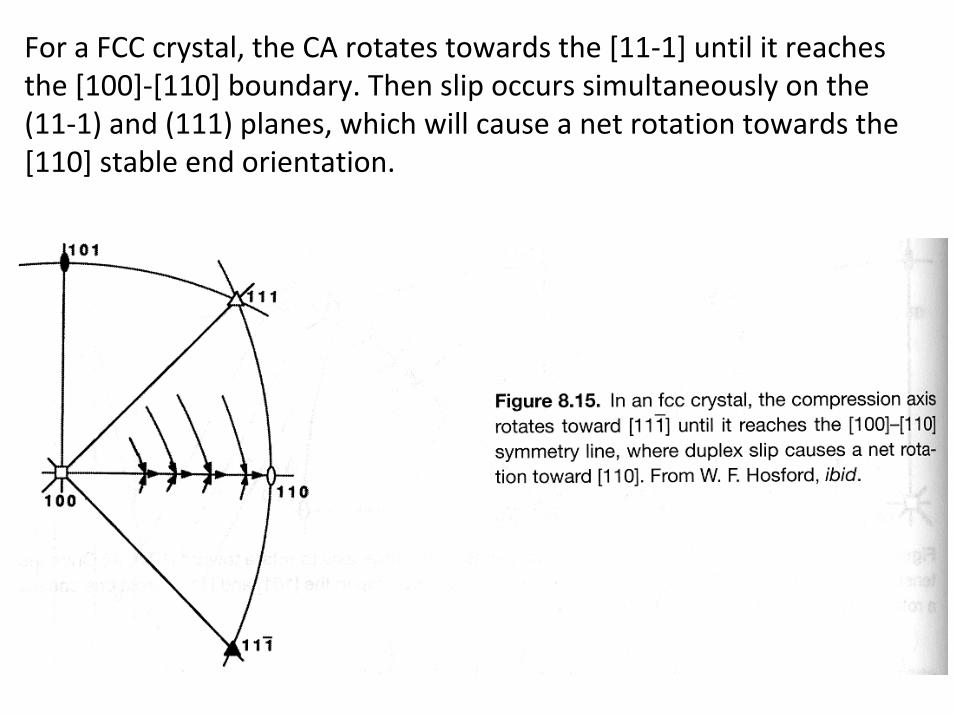
For a FCC crystal, the CA rotates towards the [11‐1] until it reaches the [100]‐[110] boundary. Then slip occurs simultaneously on the (11‐1) and (111) planes, which will cause a net rotation towards the[110] stable end orientation.
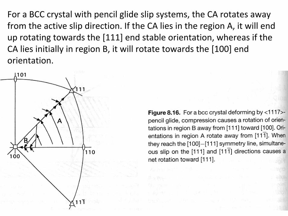
For a BCC crystal with pencil glide slip systems, the CA rotates away from the active slip direction. If the CA lies in the region A, it will end up rotating towards the [111] end stable orientation, whereas if the CA lies initially in region B, it will rotate towards the [100] end orientation.
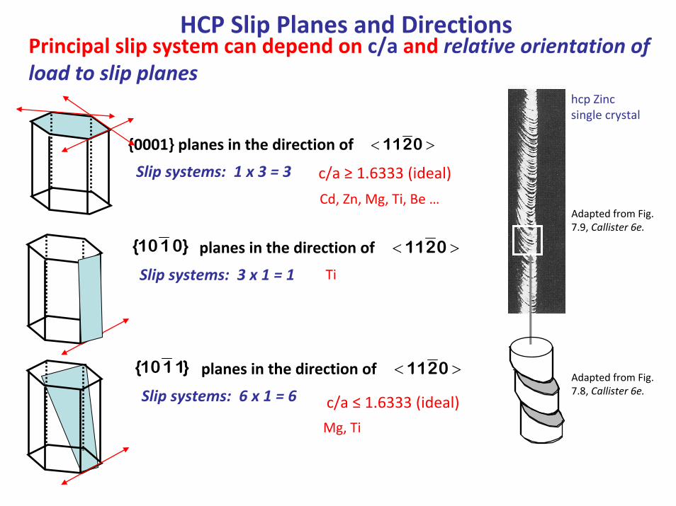
HCP Slip Planes and Directions
{0001} planes in the direction of
Slip systems: 1 x 3 = 3
<112 0 >
planes in the direction of
Slip systems: 3 x 1 = 1
Principal slip system can depend on c/a and relative orientation of load to slip planes
{10 1 0} <112 0 >
planes in the direction of
Slip systems: 6 x 1 = 6 {10 1 1} <112 0 >
c/a ≥ 1.6333 (ideal)
c/a ≤ 1.6333 (ideal)
hcp Zinc single crystal
Adapted from Fig. 7.9, Callister 6e.
Adapted from Fig. 7.8, Callister 6e.
Cd, Zn, Mg, Ti, Be …
Ti
Mg, Ti
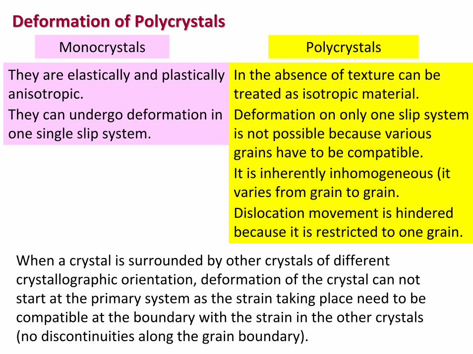
Deformation of Deformation of PolycrystalsPolycrystalsMonocrystals Polycrystals
They are elastically and plastically anisotropic.They can undergo deformation in one single slip system.
In the absence of texture can be treated as isotropic material.Deformation on only one slip system is not possible because various grains have to be compatible.It is inherently inhomogeneous (it varies from grain to grain.Dislocation movement is hindered because it is restricted to one grain.
When a crystal is surrounded by other crystals of different crystallographic orientation, deformation of the crystal can notstart at the primary system as the strain taking place need to be compatible at the boundary with the strain in the other crystals(no discontinuities along the grain boundary).
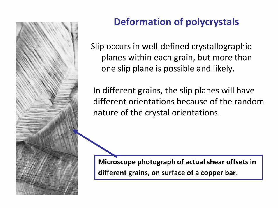
Microscope photograph of actual shear offsets in different grains, on surface of a copper bar.
Deformation of polycrystals
Slip occurs in well‐defined crystallographic planes within each grain, but more than one slip plane is possible and likely.
In different grains, the slip planes will have different orientations because of the random nature of the crystal orientations.
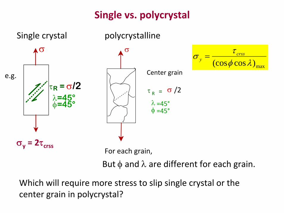
Single vs. polycrystal
τR = σ/2λ=45°φ=45°
σSingle crystal polycrystalline
e.g.
σy = 2τcrss
τ R = σ /2
λ =45°φ =45°
σ
Center grain
For each grain,
max)cos(cos λφτσ crss
y =
But φ and λ are different for each grain.
Which will require more stress to slip single crystal or the center grain in polycrystal?
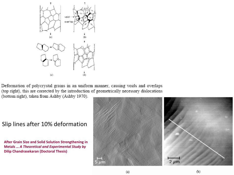
Slip lines after 10% deformation
After Grain Size and Solid Solution Strengthening in Metals … A Theoretical and Experimental Study by Dilip Chandrasekaran (Doctoral Thesis)
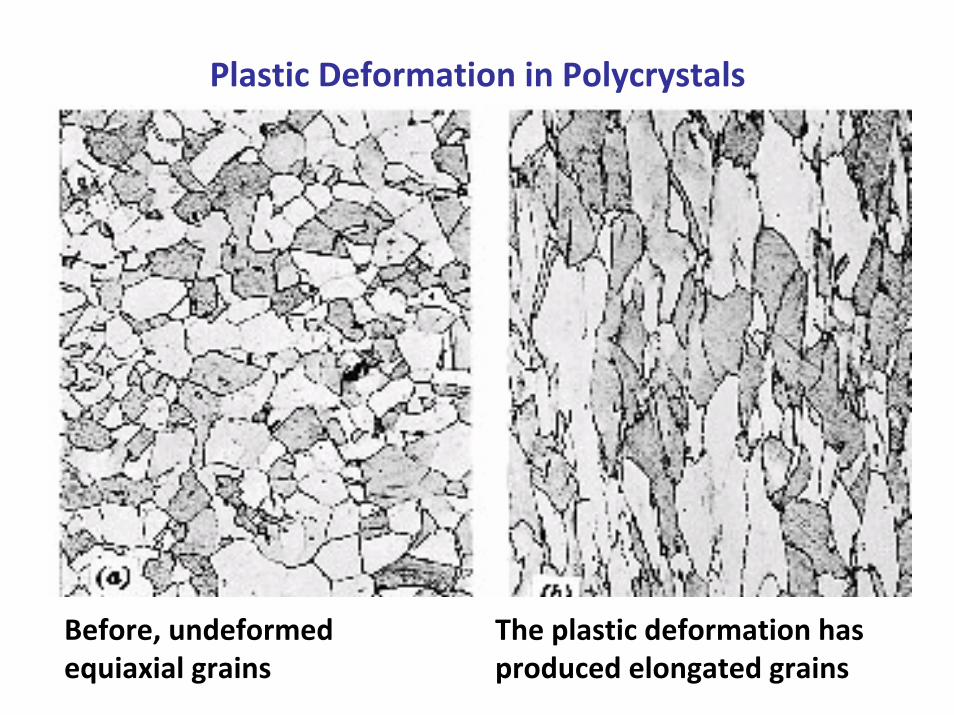
Plastic Deformation in Polycrystals
Before, undeformedequiaxial grains
The plastic deformation has produced elongated grains
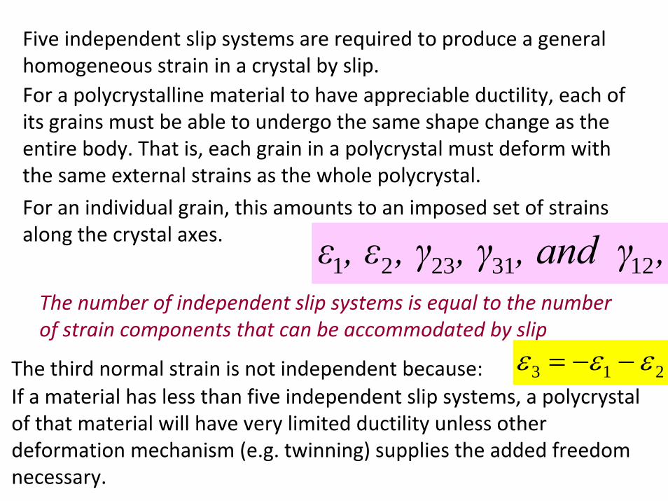
Five independent slip systems are required to produce a general homogeneous strain in a crystal by slip.For a polycrystalline material to have appreciable ductility, each of its grains must be able to undergo the same shape change as the entire body. That is, each grain in a polycrystal must deform with the same external strains as the whole polycrystal.
,, and γ, γ, γ, εε 12312321The number of independent slip systems is equal to the number of strain components that can be accommodated by slip
The third normal strain is not independent because: 213 εεε −−=If a material has less than five independent slip systems, a polycrystalof that material will have very limited ductility unless other deformation mechanism (e.g. twinning) supplies the added freedomnecessary.
For an individual grain, this amounts to an imposed set of strains along the crystal axes.
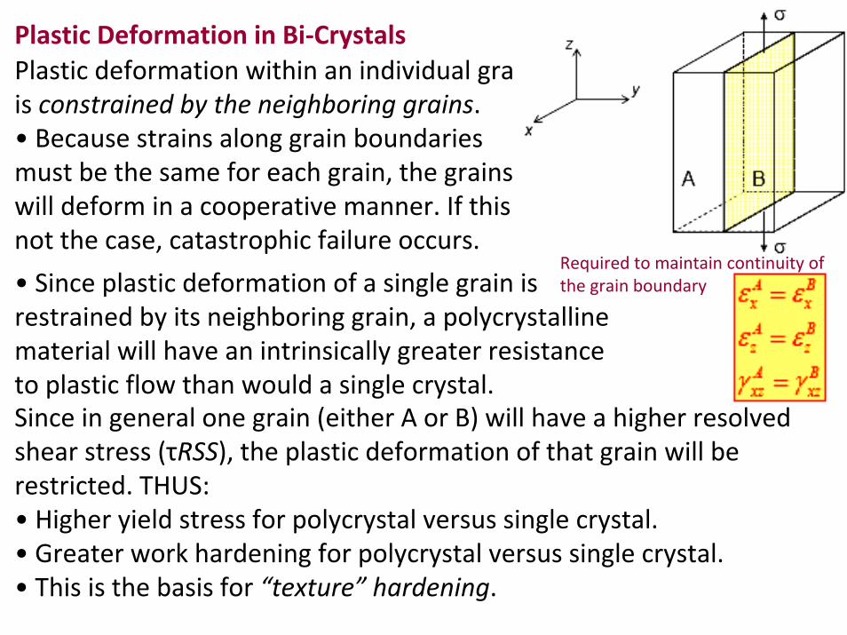
Plastic deformation within an individual grain is constrained by the neighboring grains.• Because strains along grain boundaries must be the same for each grain, the grains will deform in a cooperative manner. If this is not the case, catastrophic failure occurs.
Required to maintain continuity of the grain boundary
Plastic Deformation in Bi‐Crystals
Since in general one grain (either A or B) will have a higher resolved shear stress (τRSS), the plastic deformation of that grain will be restricted. THUS: • Higher yield stress for polycrystal versus single crystal.• Greater work hardening for polycrystal versus single crystal.• This is the basis for “texture” hardening.
• Since plastic deformation of a single grain is restrained by its neighboring grain, a polycrystalline material will have an intrinsically greater resistance to plastic flow than would a single crystal.
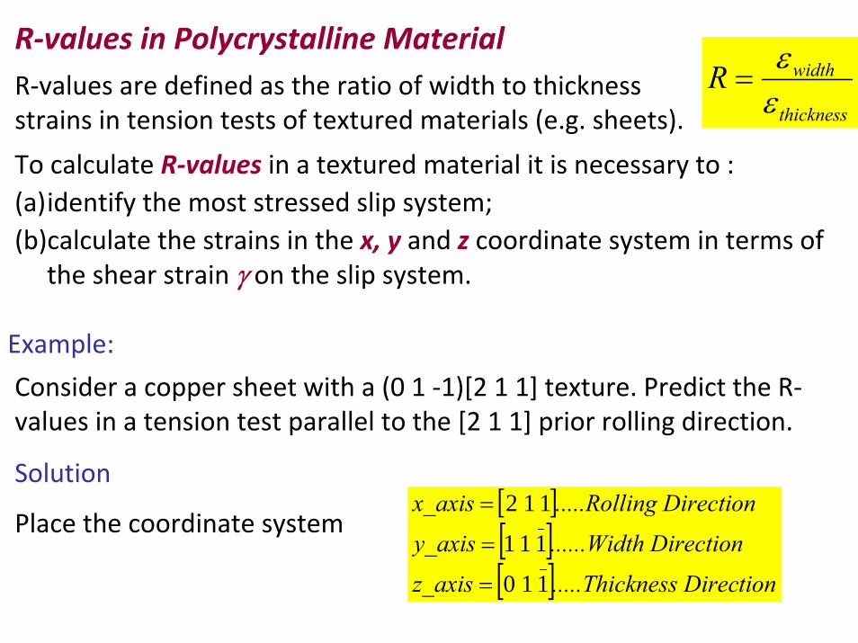
R‐values in Polycrystalline MaterialR‐values are defined as the ratio of width to thickness strains in tension tests of textured materials (e.g. sheets). thickness
widthRεε
=
To calculate R‐values in a textured material it is necessary to :(a)identify the most stressed slip system; (b)calculate the strains in the x, y and z coordinate system in terms of
the shear strain γ on the slip system.
Example:
Consider a copper sheet with a (0 1 ‐1)[2 1 1] texture. Predict the R‐values in a tension test parallel to the [2 1 1] prior rolling direction.
Solution
Place the coordinate system[ ][ ][ ] tionness Direc.....Thick z_axis
nh Directio......Widt y_axis
onng Directi.....Rolli x_axis
110
111
112
=
=
=
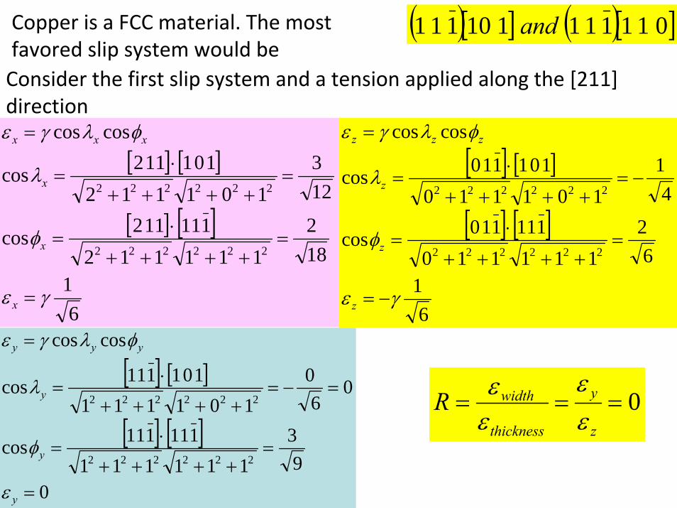
Copper is a FCC material. The most favored slip system would be
( )[ ] ( )[ ]011111110111 and
Consider the first slip system and a tension applied along the [211] direction
[ ] [ ]
[ ] [ ]
61
182
1111121 1 11 1 2cos
123
1011121 0 11 1 2cos
coscos
222222
222222
γε
φ
λ
φλγε
=
=++++
⋅=
=++++
⋅=
=
x
x
x
xxx
[ ] [ ]
[ ] [ ]
61
62
1111101 1 11 1 0cos
41
1011101 0 11 1 0cos
coscos
222222
222222
γε
φ
λ
φλγε
−=
=++++
⋅=
−=++++
⋅=
=
z
z
z
zzz
[ ] [ ]
[ ] [ ]
09
3111111
1 1 11 1 1cos
06
0101111
1 0 11 1 1cos
coscos
222222
222222
=
=++++
⋅=
=−=++++
⋅=
=
y
y
y
yyy
ε
φ
λ
φλγε
0===z
y
thickness
widthRεε
εε