DEFINITY AUDIX System Release 4 - PDF.TEXTFILES.COM
72
DEFINITY ® AUDIX ® System Release 4.0 System Description Pocket Reference 585-300-214 Comcode 108356106 Issue 1 May 1999
Transcript of DEFINITY AUDIX System Release 4 - PDF.TEXTFILES.COM
DEFINITY® AUDIX® SystemRelease 4.0
System Description Pocket Reference
585-300-214Comcode 108356106Issue 1May 1999
Copyright 1999, Lucent TechnologiesAll Rights Reserved, Printed in U.S.A.
NoticeEvery effort was made to ensure that the information in this book was complete and accurate at the time of printing. However, information is subject to change.
Your Responsibility for Your System’s SecurityToll fraud is the unauthorized use of your telecommunications system by an unautho-rized party, for example, persons other than your company’s employees, agents, sub-contractors, or persons working on your company’s behalf. Note that there may be a risk of toll fraud associated with your telecommunications system and, if toll fraud occurs, it can result in substantial additional charges for your telecommunications services.
You and your system manager are responsible for the security of your system, such as programming and configuring your equipment to prevent unauthorized use. The system manager is also responsible for reading all installation, instruction, and system adminis-tration documents provided with this product in order to fully understand the features that can introduce risk of toll fraud and the steps that can be taken to reduce that risk. Lucent Technologies does not warrant that this product is immune from or will prevent unauthorized use of common-carrier telecommunication services or facilities accessed through or connected to it. Lucent Technologies will not be responsible for any charges that result from such unauthorized use.
Lucent Technologies Fraud InterventionIf you suspect you are being victimized by toll fraud and you need technical support or assistance, call the appropriate BCS National Customer Care Center telephone num-ber. Users of the MERLIN®, PARTNER®, and System 25 products should call 1 800 628 2888. Users of the System 75, System 85, DEFINITY® Generic 1, 2 and 3, and DEFINITY® ECS products should call 1 800 643 2353. Customers outside the continen-tal United States should contact their local Lucent representative, or call one of the above numbers in the following manner:
• Dial the International Access Code; for example, 011.• Dial the country code for the U.S., that is, 01.• Lastly, dial either of the telephone numbers provided above.
Lucent Technologies Web PageThe world wide web home page for Lucent Technologies is:
http://www.lucent.com
Federal Communications Commission StatementPart 15: Class A Statement. This equipment has been tested and found to comply with the limits for a Class A digital device, pursuant to Part 15 of the FCC Rules. These limits are designed to provide reasonable protection against harmful interference when the equipment is operated in a commercial environment. This equipment generates, uses, and can radiate radio-frequency energy and, if not installed and used in accordance with the instructions, may cause harmful interference to radio communications. Opera-tion of this equipment in a residential area is likely to cause harmful interference, in which case the user will be required to correct the interference at his own expense.
Industry Canada (IC) Interference InformationThis digital apparatus does not exceed the Class A limits for radio noise emissions set out in the radio interference regulations of Industry Canada.
Le Présent Appareil Nomérique n’émet pas de bruits radioélectriques dépassant les lim-ites applicables aux appareils numériques de la class A préscrites dans le reglement sur le brouillage radioélectrique édicté par le Industrie Canada.
TrademarksSee the preface of this document.
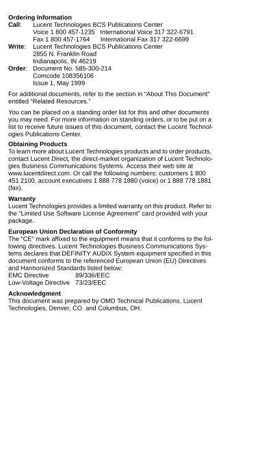
Ordering InformationCall: Lucent Technologies BCS Publications Center
Voice 1 800 457-1235 International Voice 317 322-6791Fax 1 800 457-1764 International Fax 317 322-6699
Write: Lucent Technologies BCS Publications Center2855 N. Franklin RoadIndianapolis, IN 46219
Order: Document No. 585-300-214Comcode 108356106Issue 1, May 1999
For additional documents, refer to the section in “About This Document” entitled “Related Resources.”
You can be placed on a standing order list for this and other documents you may need. For more information on standing orders, or to be put on a list to receive future issues of this document, contact the Lucent Technol-ogies Publications Center.
Obtaining ProductsTo learn more about Lucent Technologies products and to order products, contact Lucent Direct, the direct-market organization of Lucent Technolo-gies Business Communications Systems. Access their web site at www.lucentdirect.com. Or call the following numbers: customers 1 800 451 2100, account executives 1 888 778 1880 (voice) or 1 888 778 1881 (fax).
WarrantyLucent Technologies provides a limited warranty on this product. Refer to the “Limited Use Software License Agreement” card provided with your package.
European Union Declaration of ConformityThe “CE” mark affixed to the equipment means that it conforms to the fol-lowing directives. Lucent Technologies Business Communications Sys-tems declares that DEFINITY AUDIX System equipment specified in this document conforms to the referenced European Union (EU) Directives and Harmonized Standards listed below:EMC Directive 89/336/EEC Low-Voltage Directive 73/23/EEC
AcknowledgmentThis document was prepared by OMD Technical Publications, Lucent Technologies, Denver, CO. and Columbus, OH.
DEFINITY AUDIX System Release 4.0System Description Pocket Reference 585-300-214
Issue 1May 1999
iv
Contents
Contents iv
About this Book viiIntended Audiences vii
Supported Product Releases vii
Special Terminology vii
Trademarks viii
How to Order Additional Documentation viii
How to Comment on This Book viii
1 Features and Compatibility 1-1Feature Overview 1-1
Features for the Customer Organization 1-1
Features for the Subscriber 1-2
Features for the System Administrator 1-3
Compatibility 1-4
Switches 1-4
Native and Non-native Mode 1-5
2 Design and Operation 2-1TN568 Circuit Pack 2-2
Port Board Emulation 2-2
Flashware 2-2
Hard Disk Drive 2-2
Software 2-3
Networking 2-3
MO Disk Drive 2-7
Faceplate 2-8
On-board Cables 2-9
Operating Requirements 2-9
Space Requirements 2-9
Power Requirements 2-12
Environmental Requirements 2-12
DEFINITY AUDIX System Release 4.0System Description Pocket Reference 585-300-214
Issue 1May 1999
v
3 Capacity and Sizing 3-1Voice Ports 3-1
Features that Affect Voice Ports 3-3
Voice Storage 3-4
Voice Storage for Announcement Sets 3-4
INTUITY Message Manager 3-5
Backup Limits on the MO Disk Drive 3-6
A Transition Notes A-1System Design A-1
Native and Non-native Support A-1
Voice Ports A-2
Digital Networking Port A-3
Alarm Origination A-4
LEDs A-5
MO Disk Drive A-5
Switch Integration A-6
DCS Networking A-6
Analog Port Emulation A-6
Limited Availability for Control Link Integration A-7
B Customer Responsibilities B-1Staff B-1
Environmental Requirements B-1
Cable Connections B-3
Abbreviations AB-1
Glossary GL-1
Index IN-1

Intended Audiences
vii
DEFINITY AUDIX System Release 4.0System Description Pocket Reference 585-300-214
Issue 1May 1999
About this BookThis book describes the DEFINITY® AUDIX® system Release 4.0. This book is not intended to replace or modify instructions provided in task-specific documentation for the DEFINITY AUDIX system.
Intended Audiences
This book was designed for the following Lucent Technologies audiences:
■ Customers
■ Marketing and sales teams
■ Field technicians
■ Technical support organizations
■ Educators and trainers
Supported Product Releases
This book covers DEFINITY AUDIX system Release 4.0. Appendix A also includes some important changes from previous releases of the system.
Special Terminology
This book uses the word system to abbreviate the name of the DEFINITY AUDIX system. Although Lucent Technologies’ documentation sometimes uses the word system to refer to other products, such as DEFINITY communication servers, this document uses the word switch to refer to Lucent Technologies switches.
Lucent Technologies’ Technical Services Organization (TSO) and its satellite organizations, such as the Technical Services Center (TSC), the Sales Design & Support Center (SDSC), and the Multimedia Messaging Implementation Support Center (MMISC), provide technical support for Lucent Technologies customers in the U.S. Regional Centers of Excellence (COEs) support Lucent Technologies customers outside the U.S. This book broadly categorizes all of these organizations as the Remote Services Center (RSC).
DEFINITY AUDIX System Release 4.0System Description Pocket Reference 585-300-214
Issue 1May 1999
Trademarks
viii
Trademarks
This book references the following products trademarked by Lucent Technologies:
■ DEFINITY®
■ INTUITY™
■ AUDIX®
■ ProLogix™
This book references the following products trademarked by their respective vendors:
■ Windows®, Microsoft Corporation
■ dBASE III PLUS®, Ashton-Tate
■ U.S. Robotics®, 3Com Corporation
■ Sportster®, 3Com Corporation
How to Order Additional Documentation
In addition to this book, installation, maintenance, and administration books are available for the DEFINITY AUDIX system.
These books or any other Lucent Technologies product documentation can be ordered from the Lucent Technologies Product Publications Catalog website:
www.lucent.com/enterprise/documentation
How to Comment on This Book
The reader comment card is located in the front of this book. While we have tried to make this document fit your needs, we are interested in your suggestions for improving it and encourage you to complete and return a reader comment card.
Please send your comments to:
Lucent TechnologiesProduct Publications DepartmentRoom 22-2J2011900 North Pecos StreetDenver, CO 80234Fax: (303) 538-1741
Features and Compatibility
1-1Feature Overview
DEFINITY AUDIX System Release 4.0System Description Pocket Reference 585-300-214
Issue 1May 1999
Chapter 1 — Features and CompatibilityWith the high-quality voice messaging system DEFINITY AUDIX system Release 4.0, customers don’t have to answers telephones, and they can exchange messages at times when it is unnecessary or inconvenient to talk in person. The DEFINITY AUDIX system saves valuable office space and simplifies system administration by residing inside the customer’s switch and sharing a single administration terminal. These features, as well as new enhancements for reliability, make the DEFINITY AUDIX system Release 4.0 a desirable voice messaging solution for customers worldwide.
Feature Overview
The DEFINITY AUDIX system offers many features for customer organizations, individual subscribers, and DEFINITY AUDIX system administrators to help streamline information exchange among employees.
Features for the Customer Organization
Here are a few of the things the DEFINITY AUDIX system can do to help improve voice messaging efficiency in customer organizations:
■ Support up to 2000 local subscribers and 100,000 remote subscribers
■ Store up to 100 hours of voice messages
■ Exchange messages with other voice messaging systems via Digital Networking and Audio Messaging Interchange Specification (AMIS) Analog Networking
■ Post greetings and instructions in up to 9 languages from 30 available announcement sets, including a set for teletypewriters (TTYs)
■ Answer calls with different messages according to the time of day and holidays
■ Broadcast messages to large groups of subscribers simultaneously
■ Record messages with the highest voice quality available for digital voice messaging1
■ Deter toll fraud with the Call Transfer Restriction features and Administration Password Aging
■ Allow customers to track and bill subscribers’ calls with the Administration and Data Acquisition Package (ADAP)
1. AUDIX software uses a voice-encoding algorithm known as code-excited linear predication (CELP). CELP captures the nuances and subtle inflections of the human voice, which are an integral part of interpersonal communication.
DEFINITY AUDIX System Release 4.0System Description Pocket Reference 585-300-214
Issue 1May 1999
Features and Compatibility
1-2Feature Overview
■ Maintain a direct connection with Lucent Technologies’ Remote Services Center (RSC) to spur immediate support for maintenance problems
■ Ensure the stability of services by automatically backing up data on removable optical disks (also called MO disks)
■ Save money with a small voice messaging system that resides in the customer’s switch
Savings from A Smaller SystemThe space the DEFINTY AUDIX system Release 4.0 requires from the customer’s switch has decreased from previous releases of the system by 60%. The system now only requires two universal port slots in the customer’s DEFINITY switch or one slot in a Compact Modular Cabinet (CMC),2 while previous releases required five slots.
For smaller switches, such as the CMC, a voice messaging system that only takes one or two slots can make expanding the customer’s telecommunications capacity much more efficient in the long run. With a two-slot voice messaging system, customers can further expand their telecommunications capacities—adding voice ports or local area network (LAN) features, for example—before they must invest in switch upgrades.
Features for the Subscriber
Subscribers can perform many tasks with the DEFINITY AUDIX system that make communication faster, easier, and more convenient:
■ Store incoming and outgoing messages in a voice mailbox
■ Use a streamlined voice menu to speed through complex transactions
■ Post multiple personal greetings on the system, which subscribers can change according to their availability
■ Compose spoken messages with Voice Mail, which they can send to one or more other subscribers on the DEFINITY AUDIX system
■ Send messages to many recipients at once using mailing lists
■ Address voice mail messages by typing recipients’ names, rather than their extensions, on their telephone keypads
■ Advance or rewind messages as they listen
■ Receive visual notification of new messages with message waiting indicators (MWIs)—lights or display screens on subscribers’ telephones that indicate new messages
2. For the system to take one slot, it must be installed in slot 6.
DEFINITY AUDIX System Release 4.0System Description Pocket Reference 585-300-214
Issue 1May 1999
Features and Compatibility
1-3Feature Overview
■ Receive audible notification for all incoming messages or just priority messages on remote telephones or pagers
■ Retrieve, create, and send messages on their personal computers (PCs) using INTUITY Message Manager
The Advantages of INTUITY Message ManagerINTUITY Message Manager software provides DEFINITY AUDIX system subscribers access to the system through a TCP/IP connection with their PCs.
This PC interface allows subscribers to access and organize their messages much more quickly than an audible interface. Here are a few of the things DEFINITY AUDIX system subscribers can do with INTUITY Message Manager:
■ Receive visual notification of their voice mail messages on their PCs
■ View their entire message lists at once
■ Read message headers, including callers’ names and telephone numbers, to prioritize the messages they receive and listen to the messages in the order they choose
■ Access voice mail features through a visual, Windows-based interface
■ Record, edit, and play back messages and personal greetings using a mouse, rather than a telephone keypad
■ Forward and reply to messages
■ Annotate messages with a subject line
■ Save messages on their PCs, creating a permanent record of important messages and freeing storage space on the DEFINITY AUDIX system
■ Set up mailing lists and administer personal greetings and outcalling3 with ease using a keyboard
■ Access the system’s subscriber directory and mailing lists
Features for the System Administrator
The DEFINITY AUDIX system offers many features that allow system administrators to easily track system use and change system functions to meet subscribers’ needs. A few of those features are described here:
3. With the Outcalling feature, the DEFINITY AUDIX system calls subscribers at a number of their choice, including pagers, to notify them of incoming messages.
DEFINITY AUDIX System Release 4.0System Description Pocket Reference 585-300-214
Issue 1May 1999
Features and Compatibility
1-4Compatibility
■ The Class of Service feature allows administrators to manage system resources by defining up to 12 categories of subscribers with varying access to system features.
■ The Traffic Reports feature and ADAP allow administrators to effectively track subscribers’ system use, identify where to allocate system resources, and decide when to upgrade hardware.
■ The Administration Password Aging feature helps prevent unauthorized system access.
■ The Alarm Origination feature provides the administrator immediate technical support by automatically calling Lucent Technologies’ RSC to report alarms.
Compatibility
Before customers install the DEFINITY AUDIX system, they should ensure they have a switch release that can accommodate the system.
Switches
The DEFINITY AUDIX system can operate in any of the following switches:
■ System 75 R1V3
■ System 75 R1V3n
■ System 75 XE
■ DEFINITY Communications System Generic 1
■ DEFINITY Communications System Generic 3i
■ DEFINITY Communications System Generic 3s
■ DEFINITY Communications System Generic 3si
■ DEFINITY Communication System Generic 3csi (ProLogix)
■ DEFINITY Communications System Generic 3vs
■ DEFINITY Communications System Generic 3r
Table 1-1 lists special considerations for using the DEFINTIY AUDIX system with these switches.
DEFINITY AUDIX System Release 4.0System Description Pocket Reference 585-300-214
Issue 1May 1999
Features and Compatibility
1-5Compatibility
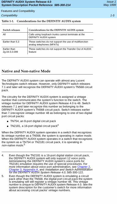
Table 1-1. Considerations for the DEFINTIY AUDIX system
Native and Non-native Mode
The DEFINITY AUDIX system can operate with almost any Lucent Technologies switch release. However, only DEFINITY switch releases 7.1 and later will recognize the DEFINITY AUDIX system’s TN568 circuit pack.
The circuitry for the DEFINITY AUDIX system is assigned a vintage number that communicates the system’s function to the switch. The vintage number for DEFINITY AUDIX system Release 4.0 is 48. Switch releases 7.1 and later recognize this number as belonging to the DEFINITY AUDIX system’s TN568 circuit pack. Switch releases earlier than 7.1recognize vintage number 48 as belonging to one of two digital port circuit packs:
■ TN754, an 8-port digital circuit pack
■ TN2181, a 16-port digital circuit pack4
When the DEFINTY AUDIX system operates in a switch that recognizes its vintage number as a TN568, the system is operating in native mode. When the DEFINITY AUDIX system operates in a switch that recognizes the system as a TN754 or TN2181 circuit pack, it is operating in non-native mode.5
Switch releases Considerations for the DEFINTIY AUDIX system
All Calls using loopback trunks cannot terminate at the DEFINITY AUDIX system
Earlier than 5.3 These switches do not support the use of multifunction analog telephones (MFATs)
Earlier than 2g.04.5.0.099
These switches do not support the Transfer Out of AUDIX feature
4. Even though the TN2181 is a 16-port digital station circuit pack, the DEFINITY AUDIX system will only support 12 voice ports. Administering the DEFINITY AUDIX system’s voice ports for TN2181 emulation requires the use of special procedures. For more information about voice port administration, see Chapter 2, Chapter 3, Appendix A, and Installation and Switch Administration for the DEFINITY AUDIX System Release 4.0, 585-300-122.
5. Even though the DEFINITY AUDIX system is emulating a circuit pack other than the TN568, the digital port circuit pack the system is emulating will still register a vintage number 48. This vintage number is unique to DEFINITY AUDIX system Release 4.0. See the system description for the customer’s switch for more information about accessing circuit packs’ vintage numbers.
DEFINITY AUDIX System Release 4.0System Description Pocket Reference 585-300-214
Issue 1May 1999
Features and Compatibility
1-6Compatibility
Operating in non-native mode does not affect subscribers’ or outside callers’ use of the system. System administrators, however, should be aware that messages from the switch, such as alarms, that refer to a TN754 or a TN2181 circuit pack the system is emulating may actually refer to the DEFINITY AUDIX system.
NOTE:
Lucent Technologies strongly recommends that the DEFINITY AUDIX system emulates a TN2181 digital port circuit pack in switch versions 2 and later. A TN2181 emulation supports a maximum of 12 voice ports, while a TN754 emulation only supports a maximum of 8 voice ports. If the DEFINITY AUDIX system emulates a TN2181 circuit pack, system expansion may be easier. Switch versions earlier than 2 do not support TN2181 circuit pack emulation.
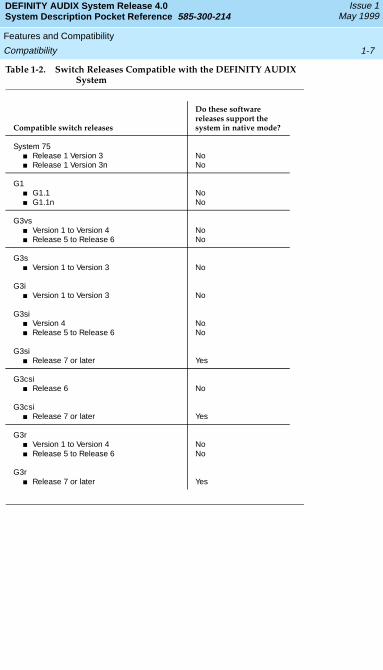
Table 1-2 shows which switches and switch software releases support the DEFINITY AUDIX system and whether or not they support the system in native mode. For more information about the TN568 circuit pack or the system’s operations native and non-native mode, see Chapter 2. For more information about Alarm Origination and the DEFINITY AUDIX system’s interactions with the switch, see Chapter 3.
DEFINITY AUDIX System Release 4.0System Description Pocket Reference 585-300-214
Issue 1May 1999
Features and Compatibility
1-7Compatibility
Table 1-2. Switch Releases Compatible with the DEFINITY AUDIX System
Compatible switch releases
Do these software releases support the system in native mode?
System 75■ Release 1 Version 3■ Release 1 Version 3n
NoNo
G1 ■ G1.1■ G1.1n
NoNo
G3vs■ Version 1 to Version 4■ Release 5 to Release 6
NoNo
G3s■ Version 1 to Version 3 No
G3i■ Version 1 to Version 3 No
G3si ■ Version 4■ Release 5 to Release 6
NoNo
G3si ■ Release 7 or later Yes
G3csi ■ Release 6 No
G3csi ■ Release 7 or later Yes
G3r ■ Version 1 to Version 4■ Release 5 to Release 6
No No
G3r ■ Release 7 or later Yes

DEFINITY AUDIX System Release 4.0System Description Pocket Reference 585-300-214
Issue 1May 1999
Features and Compatibility
1-8Compatibility
Design and Operation
2-1
DEFINITY AUDIX System Release 4.0System Description Pocket Reference 585-300-214
Issue 1May 1999
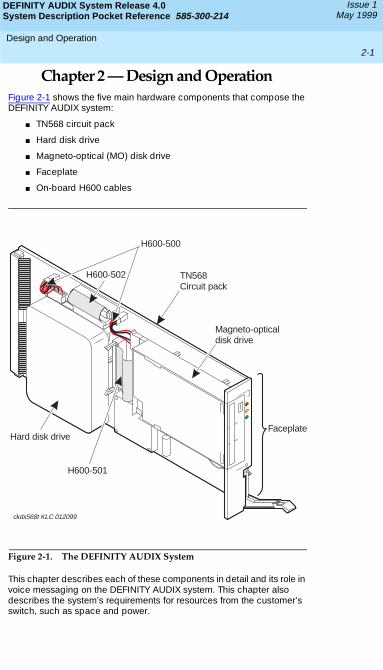
Chapter 2 — Design and OperationFigure 2-1 shows the five main hardware components that compose the DEFINITY AUDIX system:
■ TN568 circuit pack
■ Hard disk drive
■ Magneto-optical (MO) disk drive
■ Faceplate
■ On-board H600 cables
Figure 2-1. The DEFINITY AUDIX System
This chapter describes each of these components in detail and its role in voice messaging on the DEFINITY AUDIX system. This chapter also describes the system’s requirements for resources from the customer’s switch, such as space and power.
Emer Reset
Shutdown
ckdx568t KLC 012099
Hard disk drive
H600-501
Magneto-opticaldisk drive
TN568Circuit pack
Faceplate
H600-502
H600-500
DEFINITY AUDIX System Release 4.0System Description Pocket Reference 585-300-214
Issue 1May 1999
Design and Operation
2-2TN568 Circuit Pack
TN568 Circuit Pack
The TN568 circuit pack holds the systems main circuitry and performs system’s main processing functions, including message routing, self-diagnosis, and Alarm Origination.
Port Board Emulation
The TN568 holds the system’s voice ports. These voice ports correspond to the voice ports on a TN754 or TN2181 circuit pack. DEFINITY switch releases 7.1 and later recognize the TN568 circuit pack. However, the system’s voice ports interact with the switch like the voice ports on a TN754 or TN2181 circuit pack regardless of whether the system is operating in native or non-native mode. For more information about digital port emulation, see Chapter 1.
Flashware
The TN568 circuit pack uses flashware to store the sequences it uses to boot the system and programs specific to the TN568. Flashware are programs that reside on flash programmable read-only memory (FPROMs). FPROMs are hardware that reside on the TN568 and are protected from accidental erases or rewrites. Copies of all the active flashware programs are also stored on the hard disk.
If the customer installs software upgrades or fixes, the new program is transferred from a MO disk to the hard disk. When the system reboots, the new program automatically transfers from the hard disk to the FPROMs and replaces the existing flashware.
Hard Disk Drive
The hard disk drive stores the system’s AUDIX software, subscriber information and voice messages.
Voice messages that customers may store on the system include voice mail, personal greetings, automated attendants, and announcement sets—the sets of automated, verbal instructions that compose the system’s user interface.
The hard disk drive provides up to 100 hours of voice storage. The system comes with a minimum of 10 hours of voice storage. Customers can purchase additional voice storage in five-hour blocks.
DEFINITY AUDIX System Release 4.0System Description Pocket Reference 585-300-214
Issue 1May 1999
Design and Operation
2-3Hard Disk Drive
Software
AUDIX software allows the DEFINITY AUDIX system to communicate with the switch through a telephone-like interface. This type of operation is called set-type emulation. The commands that subscribers and the switch use to access the system’s software correspond to the interface on a digital telephone, or set.
The digital set the system emulates depends on whether the system is operating in native or non-native mode. In switch releases earlier than 7.1, the DEFINITY AUDIX system emulates a 7405D digital telephone. In switch releases 7.1 and later, the system communicates with the switch using an ADX16D set-type interface, through which the switch can recognize the system’s AUDIX software.1
Networking
Because of its telephone-like interface, the system can send and receive messages from other voice messaging systems as a telephone can. AUDIX software helps the system to communicate efficiently with other AUDIX systems.
The DEFINITY AUDIX system has two networking options that use these capabilities for message exchange:
■ AMIS Analog Networking
■ Digital Networking
AMIS Analog NetworkingAMIS is a standard protocol among voice messaging systems. AMIS Analog Networking uses the Message Delivery feature to send messages to subscribers on other voice messaging systems that use the AMIS protocol.
AMIS Analog Networking sends a message through the system’s voice ports much like a telephone call. The recipient’s voice mail system receives the message as it would receive any other voice message and stores it in the recipient’s voice mailbox. Other voice messaging systems can send messages to the DEFINITY AUDIX system in the same way.
Digital NetworkingDigital Networking is an efficient way for DEFINITY AUDIX, AUDIX R1, INTUITY, and Interchange systems to communicate with each other without using the systems’ voice ports. The DEFINITY AUDIX system has one Digital Networking port that can be dedicated solely to Digital
1. For more information about digital station emulations, see Installation and Switch Administration for the DEFINITY AUDIX System Release 4.0, 585-300-122.
DEFINITY AUDIX System Release 4.0System Description Pocket Reference 585-300-214
Issue 1May 1999
Design and Operation
2-4Hard Disk Drive
Networking features. In its maximum configuration, the DEFINITY AUDIX system can connect through this Digital Networking channel to up to 100 remote systems, or nodes.2
Digital Networking offers several advantages over AMIS Analog Networking:
■ Digital Networking is more secure than AMIS Analog Networking.
■ Digital Networking uses Lucent Technologies’ Digital Communications Protocol (DCP) to send subscriber profiles and message status information along with messages, while AMIS does not send this information.
■ Digital Networking messages have higher voice quality than AMIS messages because Digital Networking uses CELP encoding.
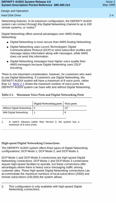
There is one important consideration, however, for customers who want to use Digital Networking. If customers use Digital Networking, the DEFINITY AUDIX system will have a maximum of 8 voice ports, rather than 12. Table 2-1 shows the maximum number of voice ports the DEFINTIY AUDIX system can have with and without Digital Networking.
High-speed Digital Networking Connections
The DEFINTIY AUDIX system offers three types of Digital Networking configurations: DCP Mode 1, DCP Mode 2, and DCP Mode 3.
DCP Mode 1 and DCP Mode 3 connections are high-speed Digital Networking connections. DCP Mode 1 and DCP Mode 3 connections require high-speed facilities to operate, but these connections offer advantages where there is heavy voice messaging traffic among customer sites. These high-speed Digital Networking connections can accommodate the maximum numbers of local subscribers (2000) and remote subscribers (100,000) the system allows.
2. This configuration is only available with high-speed Digital Networking connections.
Table 2-1. Maximum Voice Ports and Digital Networking Ports
Digital Networking ports Voice ports
Without Digital Networking 0 121
1. In switch releases earlier than Version 2, the system has amaximum of 8 voice ports.
With Digital Networking 1 8
DEFINITY AUDIX System Release 4.0System Description Pocket Reference 585-300-214
Issue 1May 1999
Design and Operation
2-5Hard Disk Drive
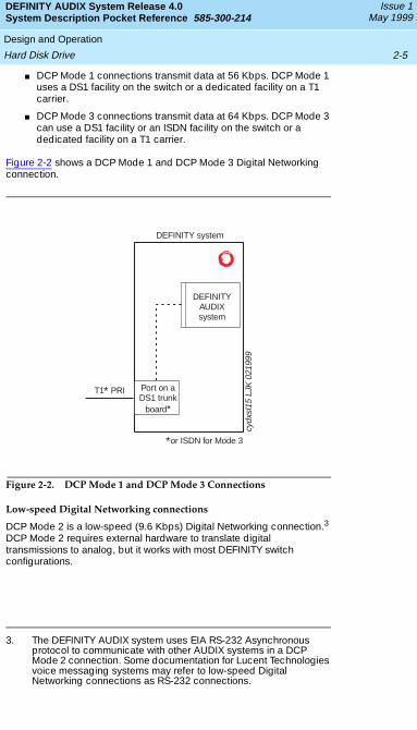
■ DCP Mode 1 connections transmit data at 56 Kbps. DCP Mode 1 uses a DS1 facility on the switch or a dedicated facility on a T1 carrier.
■ DCP Mode 3 connections transmit data at 64 Kbps. DCP Mode 3 can use a DS1 facility or an ISDN facility on the switch or a dedicated facility on a T1 carrier.
Figure 2-2 shows a DCP Mode 1 and DCP Mode 3 Digital Networking connection.
Figure 2-2. DCP Mode 1 and DCP Mode 3 Connections
Low-speed Digital Networking connections
DCP Mode 2 is a low-speed (9.6 Kbps) Digital Networking connection.3 DCP Mode 2 requires external hardware to translate digital transmissions to analog, but it works with most DEFINITY switch configurations.
3. The DEFINITY AUDIX system uses EIA RS-232 Asynchronous protocol to communicate with other AUDIX systems in a DCP Mode 2 connection. Some documentation for Lucent Technologies voice messaging systems may refer to low-speed Digital Networking connections as RS-232 connections.
DEFINITY system
cydx
sl15
LJK
021
999
T1 PRI*
*or ISDN for Mode 3
DEFINITYAUDIXsystem
Port on aDS1 trunk
board*
DEFINITY AUDIX System Release 4.0System Description Pocket Reference 585-300-214
Issue 1May 1999
Design and Operation
2-6Hard Disk Drive
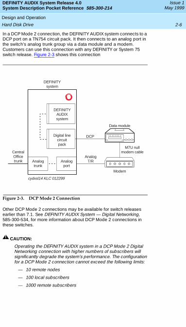
In a DCP Mode 2 connection, the DEFINITY AUDIX system connects to a DCP port on a TN754 circuit pack. It then connects to an analog port in the switch’s analog trunk group via a data module and a modem. Customers can use this connection with any DEFINITY or System 75 switch release. Figure 2-3 shows this connection
Figure 2-3. DCP Mode 2 Connection
Other DCP Mode 2 connections may be available for switch releases earlier than 7.1. See DEFINITY AUDIX System — Digital Networking, 585-300-534, for more information about DCP Mode 2 connections in these switches.
! CAUTION:
Operating the DEFINITY AUDIX system in a DCP Mode 2 Digital Networking connection with higher numbers of subscribers will significantly degrade the system’s performance. The configuration for a DCP Mode 2 connection cannot exceed the following limits:
— 10 remote nodes
— 100 local subscribers
— 1000 remote subscribers
DEFINITYsystem
cydxsl14 KLC 012299
M7U nullmodem cable
Data module
Modem
AnalogT/R
DCP
Analogport
Analogtrunk
CentralOfficetrunk
Digital linecircuitpack
DEFINITYAUDIXsystem
DEFINITY AUDIX System Release 4.0System Description Pocket Reference 585-300-214
Issue 1May 1999
Design and Operation
2-7MO Disk Drive
MO Disk Drive
Customers and Lucent Technologies technicians can use the MO disk drive to back up data at regular intervals, load software when it is necessary, and transfer data during installations, migrations, or system moves.
Lucent Technologies ships four MO disks with the DEFINITY AUDIX system:
■ One generic disk, which holds the customer’s uniquely configured AUDIX software
■ One language disk, which holds the customer’s primary announcement set
■ Two 640 MB blank disks, which the customer can use for system backups
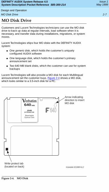
Lucent Technologies will also provide a MO disk for each Multilingual announcement set the customer buys. Figure 2-4 shows a MO disk, which looks similar to a 3.5-inch disk for a PC.
.
Figure 2-4. MO Disk
640640MB
2048BYTES/SECTOR
h1dxdskt 021999 KLC
Arrow indicatingdirection to insertMO disk
Write protect tab(located on back)
DEFINITY AUDIX System Release 4.0System Description Pocket Reference 585-300-214
Issue 1May 1999
Design and Operation
2-8Faceplate
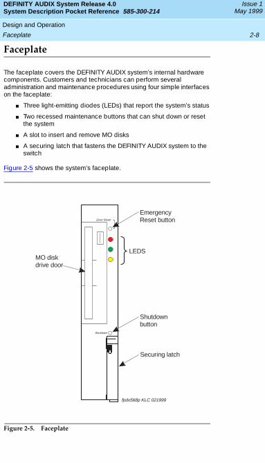
Faceplate
The faceplate covers the DEFINITY AUDIX system’s internal hardware components. Customers and technicians can perform several administration and maintenance procedures using four simple interfaces on the faceplate:
■ Three light-emitting diodes (LEDs) that report the system’s status
■ Two recessed maintenance buttons that can shut down or reset the system
■ A slot to insert and remove MO disks
■ A securing latch that fastens the DEFINITY AUDIX system to the switch
Figure 2-5 shows the system’s faceplate.
.
Figure 2-5. Faceplate
Emer Reset
Shutdown
Shutdownbutton
EmergencyReset button
LEDS
Securing latch
MO diskdrive door
fpdx568p KLC 021999
DEFINITY AUDIX System Release 4.0System Description Pocket Reference 585-300-214
Issue 1May 1999
Design and Operation
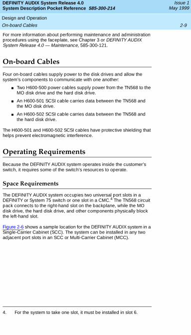
2-9On-board Cables
For more information about performing maintenance and administration procedures using the faceplate, see Chapter 3 or DEFINITY AUDIX System Release 4.0 — Maintenance, 585-300-121.
On-board Cables
Four on-board cables supply power to the disk drives and allow the system’s components to communicate with one another:
■ Two H600-500 power cables supply power from the TN568 to the MO disk drive and the hard disk drive.
■ An H600-501 SCSI cable carries data between the TN568 and the MO disk drive.
■ An H600-502 SCSI cable carries data between the TN568 and the hard disk drive.
The H600-501 and H600-502 SCSI cables have protective shielding that helps prevent electromagnetic interference.
Operating Requirements
Because the DEFINITY AUDIX system operates inside the customer’s switch, it requires some of the switch’s resources to operate.
Space Requirements
The DEFINITY AUDIX system occupies two universal port slots in a DEFINITY or System 75 switch or one slot in a CMC.4 The TN568 circuit pack connects to the right-hand slot on the backplane, while the MO disk drive, the hard disk drive, and other components physically block the left-hand slot.
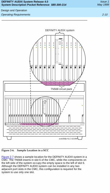
Figure 2-6 shows a sample location for the DEFINITY AUDIX system in a Single-Carrier Cabinet (SCC). The system can be installed in any two adjacent port slots in an SCC or Multi-Carrier Cabinet (MCC).
4. For the system to take one slot, it must be installed in slot 6.
DEFINITY AUDIX System Release 4.0System Description Pocket Reference 585-300-214
Issue 1May 1999
Design and Operation
2-10Operating Requirements
Figure 2-6. Sample Location in a SCC
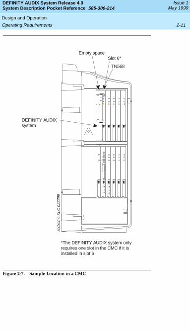
Figure 2-7 shows a sample location for the DEFINITY AUDIX system in a CMC. The TN568 inserts in slot 6 of the CMC, while the components on the left side of the system occupy the empty space to the left of slot 6. Although the DEFINITY AUDIX system can be installed in any two adjacent port slots in the CMC, this configuration is required for the system to use only one slot.
1 2 3 4 5 6 7
TONE-
CLOCK
TONE
DET/GEN
EXPN
INTFC
EXPN
INTFC
POWER SUPPLY
8 9 10 11 12 13 14 15 16
POWER UNITPACKET
CONT
NET
CONT
PROCR
INTFC
MEMORYPROCRDUPN
INTFC
scdx568p KLC 021999
4 5 6 7 8 9 10 11 12 13 14 15 16
DEFINITY AUDIX system
TN568 circuit pack
DEFINITY AUDIX System Release 4.0System Description Pocket Reference 585-300-214
Issue 1May 1999
Design and Operation
2-11Operating Requirements
Figure 2-7. Sample Location in a CMC
scdx
cmc
KLC
022
299
MAJ
MIN
ON
OFF
AM
BE
RC
AR
DIN
US
E
RE
DE
ME
RX
FE
RO
NE
MX
FR
AUTO
TN798B
TN2182B
DEFINITY AUDIXsystem
Empty spaceSlot 6*
TN568
*The DEFINITY AUDIX system onlyrequires one slot in the CMC if it isinstalled in slot 6
DEFINITY AUDIX System Release 4.0System Description Pocket Reference 585-300-214
Issue 1May 1999
Design and Operation
2-12Operating Requirements
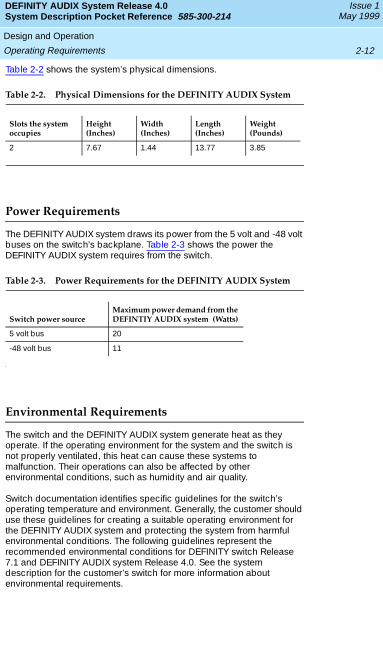
Table 2-2 shows the system’s physical dimensions.
Power Requirements
The DEFINITY AUDIX system draws its power from the 5 volt and -48 volt buses on the switch’s backplane. Table 2-3 shows the power the DEFINITY AUDIX system requires from the switch.
Environmental Requirements
The switch and the DEFINITY AUDIX system generate heat as they operate. If the operating environment for the system and the switch is not properly ventilated, this heat can cause these systems to malfunction. Their operations can also be affected by other environmental conditions, such as humidity and air quality.
Switch documentation identifies specific guidelines for the switch’s operating temperature and environment. Generally, the customer should use these guidelines for creating a suitable operating environment for the DEFINITY AUDIX system and protecting the system from harmful environmental conditions. The following guidelines represent the recommended environmental conditions for DEFINITY switch Release 7.1 and DEFINITY AUDIX system Release 4.0. See the system description for the customer’s switch for more information about environmental requirements.
Table 2-2. Physical Dimensions for the DEFINITY AUDIX System
Slots the system occupies
Height (Inches)
Width (Inches)
Length (Inches)
Weight (Pounds)
2 7.67 1.44 13.77 3.85
Table 2-3. Power Requirements for the DEFINITY AUDIX System
Switch power source Maximum power demand from the DEFINTIY AUDIX system (Watts)
5 volt bus 20
-48 volt bus 11
DEFINITY AUDIX System Release 4.0System Description Pocket Reference 585-300-214
Issue 1May 1999
Design and Operation
2-13Operating Requirements
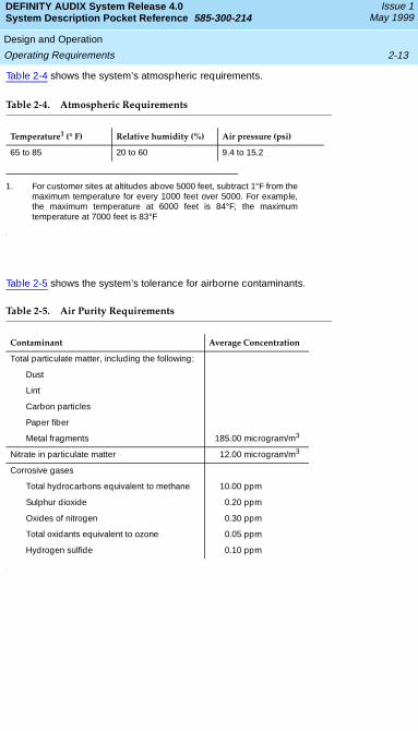
Table 2-4 shows the system’s atmospheric requirements.
Table 2-4. Atmospheric Requirements
Table 2-5 shows the system’s tolerance for airborne contaminants.
Temperature1 (° F)
1. For customer sites at altitudes above 5000 feet, subtract 1°F from themaximum temperature for every 1000 feet over 5000. For example,the maximum temperature at 6000 feet is 84°F; the maximumtemperature at 7000 feet is 83°F
Relative humidity (%) Air pressure (psi)
65 to 85 20 to 60 9.4 to 15.2
Table 2-5. Air Purity Requirements
Contaminant Average Concentration
Total particulate matter, including the following:
Dust
Lint
Carbon particles
Paper fiber
Metal fragments 185.00 microgram/m3
Nitrate in particulate matter 12.00 microgram/m3
Corrosive gases
Total hydrocarbons equivalent to methane 10.00 ppm
Sulphur dioxide 0.20 ppm
Oxides of nitrogen 0.30 ppm
Total oxidants equivalent to ozone 0.05 ppm
Hydrogen sulfide 0.10 ppm

DEFINITY AUDIX System Release 4.0System Description Pocket Reference 585-300-214
Issue 1May 1999
Design and Operation
2-14Operating Requirements
Capacity and Sizing
3-1Voice Ports
DEFINITY AUDIX System Release 4.0System Description Pocket Reference 585-300-214
Issue 1May 1999
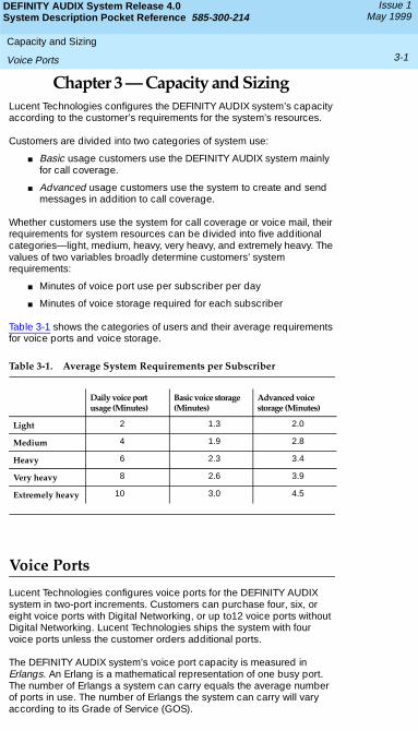
Chapter 3 — Capacity and SizingLucent Technologies configures the DEFINITY AUDIX system’s capacity according to the customer’s requirements for the system’s resources.
Customers are divided into two categories of system use:
■ Basic usage customers use the DEFINITY AUDIX system mainly for call coverage.
■ Advanced usage customers use the system to create and send messages in addition to call coverage.
Whether customers use the system for call coverage or voice mail, their requirements for system resources can be divided into five additional categories—light, medium, heavy, very heavy, and extremely heavy. The values of two variables broadly determine customers’ system requirements:
■ Minutes of voice port use per subscriber per day
■ Minutes of voice storage required for each subscriber
Table 3-1 shows the categories of users and their average requirements for voice ports and voice storage.
Voice Ports
Lucent Technologies configures voice ports for the DEFINITY AUDIX system in two-port increments. Customers can purchase four, six, or eight voice ports with Digital Networking, or up to12 voice ports without Digital Networking. Lucent Technologies ships the system with four voice ports unless the customer orders additional ports.
The DEFINITY AUDIX system’s voice port capacity is measured in Erlangs. An Erlang is a mathematical representation of one busy port. The number of Erlangs a system can carry equals the average number of ports in use. The number of Erlangs the system can carry will vary according to its Grade of Service (GOS).
Table 3-1. Average System Requirements per Subscriber
Daily voice port usage (Minutes)
Basic voice storage (Minutes)
Advanced voice storage (Minutes)
Light 2 1.3 2.0
Medium 4 1.9 2.8
Heavy 6 2.3 3.4
Very heavy 8 2.6 3.9
Extremely heavy 10 3.0 4.5
DEFINITY AUDIX System Release 4.0System Description Pocket Reference 585-300-214
Issue 1May 1999
Capacity and Sizing
3-2Voice Ports
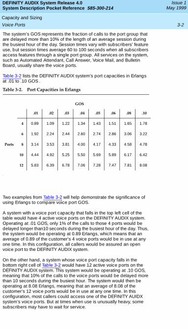
The system’s GOS represents the fraction of calls to the port group that are delayed more than 10% of the length of an average session during the busiest hour of the day. Session times vary with subscribers’ feature use, but session times average 60 to 100 seconds when all subscribers access features through a single port group. All services on the system, such as Automated Attendant, Call Answer, Voice Mail, and Bulletin Board, usually share the voice ports.
Table 3-2 lists the DEFINITY AUDIX system’s port capacities in Erlangs at .01 to .10 GOS .
Two examples from Table 3-2 will help demonstrate the significance of using Erlangs to compare voice port GOS.
A system with a voice port capacity that falls in the top left cell of the table would have 4 active voice ports on the DEFINITY AUDIX system. Operating at .01 GOS, only 1% of the calls to those 4 ports would be delayed longer than10 seconds during the busiest hour of the day. Thus, the system would be operating at 0.89 Erlangs, which means that an average of 0.89 of the customer’s 4 voice ports would be in use at any one time. In this configuration, all callers would be assured an open voice port to the DEFINITY AUDIX system.
On the other hand, a system whose voice port capacity falls in the bottom right cell of Table 3-2 would have 12 active voice ports on the DEFINITY AUDIX system. This system would be operating at .10 GOS, meaning that 10% of the calls to the voice ports would be delayed more than 10 seconds during the busiest hour. The system would then be operating at 8.08 Erlangs, meaning that an average of 8.08 of the customer’s 12 voice ports would be in use at any one time. In this configuration, most callers could access one of the DEFINITY AUIDX system’s voice ports. But at times when use is unusually heavy, some subscribers may have to wait for service.
Table 3-2. Port Capacities in Erlangs
GOS
.01 .02 .03 .04 .05 .06 .08 .10
4 0.89 1.09 1.22 1.34 1.43 1.51 1.65 1.78
6 1.92 2.24 2.44 2.60 2.74 2.86 3.06 3.22
Ports 8 3.14 3.53 3.81 4.00 4.17 4.33 4.58 4.78
10 4.44 4.92 5.25 5.50 5.69 5.89 6.17 6.42
12 5.83 6.39 6.78 7.06 7.28 7.47 7.81 8.08
DEFINITY AUDIX System Release 4.0System Description Pocket Reference 585-300-214
Issue 1May 1999
Capacity and Sizing
3-3Voice Ports
Understanding the port capacities for the DEFINITY AUDIX system Release 4.0 will help customers decide which port packages are right for their organizations’ needs.
Features that Affect Voice Ports
Some of the DEFINITY AUDIX system’s features can place varying demands on the system’s resources. Among those features that have unique requirements for voice ports are Outcalling, Automated Attendant, and Broadcast Messaging. The DOSS configurator—Lucent Technologies’ system for configuring products according to customers’ needs—calculates the requirements for these features individually. It is particularly important for customers who specify their voice port requirements to understand these demands so they can accurately predict their systems’ performance.
OutcallingFor Outcalling, the DOSS configurator uses the following estimates to calculate voice port requirements:
■ The total number of outcalls during the busiest hour of the day
■ The fraction of total outcalls that go to a pager
The DOSS configurator also assumes the following:
■ A successful outcall takes 15 seconds; an unsuccessful outcall takes 60 seconds.
■ 50% of outcalls that do not go to a pager are successful.
■ The switch treats all outcalls that go to a pager as unsuccessful.
Automated AttendantFor Automated Attendant, the DOSS configurator uses the following estimates to calculate voice port requirements:
■ The number of Automated Attendant calls during the busy hour
■ The holding time per call
Broadcast MessagingFor Broadcast Messaging, the DOSS configurator uses the following estimates to calculate voice port requirements:
■ The total number of broadcast messages the customer organization generates per day
■ The average length of a broadcast message in seconds
DEFINITY AUDIX System Release 4.0System Description Pocket Reference 585-300-214
Issue 1May 1999
Capacity and Sizing
3-4Voice Storage
Digital NetworkingUsing Digital Networking reduces the system’s maximum number of voice ports from 12 to 8. Customers who need Digital Networking and more than 8 voice ports should consider using an INTUITY messaging system. For more information about the INTUITY messaging system, see INTUITY Messaging Solutions.
AMIS Analog NetworkingWhile Digital Networking uses the Digital Networking port to send messages to remote subscribers, AMIS Analog Networking uses voice ports to send messages with the Message Delivery feature. AMIS Analog Networking does not reduce the total number of voice ports available on the system, but it does place some traffic demands on the voice ports.
The DOSS configurator uses the following estimates to calculate voice port requirements for AMIS Analog Networking and Message Delivery:
■ The total number of administered remote subscribers.
■ The number of incoming and outgoing AMIS messages during the busiest hour of the day.
■ The average length of incoming and outgoing AMIS messages.
■ The number of Message Delivery messages during the busiest hour of the day.
■ The average length of Message Delivery messages. The DOSS configurator assumes these messages have two standard characteristics:
— 50% of the calls are unsuccessful and require a retry; these calls are successful on the retry.
— An unsuccessful call requires 60 seconds.
Voice Storage
Rather than using Lucent Technologies’ formula for determining voice storage requirements, customers may specify the amount of voice storage they require. Customers who want to use multiple language sets, however, should consider voice storage requirements for the Multilingual feature in their calculations.
Voice Storage for Announcement Sets
One MO disk comes with the DEFINITY AUDIX system for each multilingual announcement set customers purchase. The Multilingual feature allows customers to use up to nine language sets at once.
The amount of available hard disk storage determines, in part, the number of announcement sets the DEFINITY AUDIX system can hold.1
DEFINITY AUDIX System Release 4.0System Description Pocket Reference 585-300-214
Issue 1May 1999
Capacity and Sizing
3-5INTUITY Message Manager
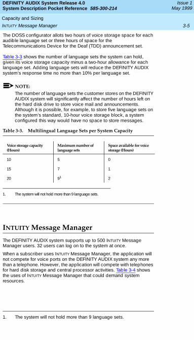
The DOSS configurator allots two hours of voice storage space for each audible language set or three hours of space for the Telecommunications Device for the Deaf (TDD) announcement set.
Table 3-3 shows the number of language sets the system can hold, given its voice storage capacity minus a two-hour allowance for each language set. Adding language sets will reduce the DEFINITY AUDIX system’s response time no more than 10% per language set.
NOTE:
The number of language sets the customer stores on the DEFINITY AUDIX system will significantly affect the number of hours left on the hard disk drive to store voice mail and announcements. Although it is possible, for example, to store five language sets on the system’s standard, 10-hour voice storage block, a system configured this way would have no space to store messages.
INTUITY Message Manager
The DEFINITY AUDIX system supports up to 500 INTUITY Message Manager users. 32 users can log on to the system at once.
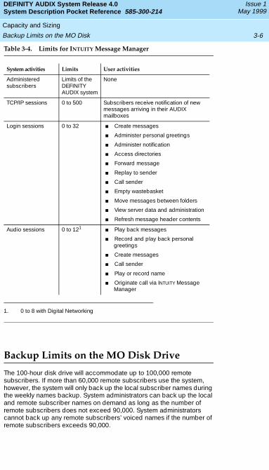
When a subscriber uses INTUITY Message Manager, the application will not compete for voice ports on the DEFINITY AUDIX system any more than a telephone. However, the application will compete with telephones for hard disk storage and central processor activities. Table 3-4 shows the uses of INTUITY Message Manager that could demand system resources.
1. The system will not hold more than 9 language sets.
Table 3-3. Multilingual Language Sets per System Capacity
Voice storage capacity (Hours)
Maximum number of language sets
Space available for voice storage (Hours)
10 5 0
15 7 1
20 91
1. The system will not hold more than 9 language sets.
2
DEFINITY AUDIX System Release 4.0System Description Pocket Reference 585-300-214
Issue 1May 1999
Capacity and Sizing
3-6Backup Limits on the MO Disk
Table 3-4. Limits for INTUITY Message Manager
Backup Limits on the MO Disk Drive
The 100-hour disk drive will accommodate up to 100,000 remote subscribers. If more than 60,000 remote subscribers use the system, however, the system will only back up the local subscriber names during the weekly names backup. System administrators can back up the local and remote subscriber names on demand as long as the number of remote subscribers does not exceed 90,000. System administrators cannot back up any remote subscribers’ voiced names if the number of remote subscribers exceeds 90,000.
System activities Limits User activities
Administered subscribers
Limits of the DEFINITY AUDIX system
None
TCP/IP sessions 0 to 500 Subscribers receive notification of new messages arriving in their AUDIX mailboxes
Login sessions 0 to 32 ■ Create messages
■ Administer personal greetings
■ Administer notification
■ Access directories
■ Forward message
■ Replay to sender
■ Call sender
■ Empty wastebasket
■ Move messages between folders
■ View server data and administration
■ Refresh message header contents
Audio sessions 0 to 121
1. 0 to 8 with Digital Networking
■ Play back messages
■ Record and play back personal greetings
■ Create messages
■ Call sender
■ Play or record name
■ Originate call via INTUITY Message Manager
Transition Notes
A-1System Design
DEFINITY AUDIX System Release 4.0System Description Pocket Reference 585-300-214
Issue 1May 1999
Appendix A — Transition NotesThe hardware design for DEFINITY AUDIX system Release 4.0 has changed significantly from previous releases of the system. The most important result of these changes is a 60% reduction in the space the system requires in the customer’s switch.
The change in system size required some changes in functionality that may impact customers who migrate from previous system releases to Release 4.0. This appendix explains these changes in detail. For more information about the design and operation of DEFINITY AUDIX system Release 4.0, see Chapter 2.
System Design
DEFINITY AUDIX system Release 4.0 uses one circuit pack, the TN568. With its additional hardware components, including the MO drive and the hard disk drive, the system occupies two universal port slots in the customer’s switch.1 Previous releases of the DEFINITY AUDIX system used two circuit packs—either a TN566 or a TN567 multifunction board and an alarm board. Because of this design, previous releases of the DEFINITY AUDIX system occupied five port slots in the customer’s switch.
Native and Non-native Support
When the DEFINITY AUDIX system operates in native mode, the switch reserves a number of port slots for the system based on the system’s size. DEFINITY AUDIX system releases earlier than 4.0 were five slots wide, so switch releases that supported the system in native mode reserved five slots for the system. Because DEFINITY AUDIX system Release 4.0 only requires two slots in the switch, switch releases that support the system in native mode will only reserve two slots for the system.1
DEFINITY switch Version 4, Version 5, and Release 6 supported DEFINITY AUDIX system releases earlier than 4.0 in native mode. However, only DEFINITY switch releases 7.1 and later will support DEFINITY AUDIX system Release 4.0 in native mode.
This change mainly impacts customers who want to migrate from DEFINITY AUDIX system releases earlier than 4.0 to DEFINITY AUDIX system Release 4.0 for use in DEFINITY switch Version 4, Version 5, or Release 6. Customers who use DEFINITY AUDIX system releases earlier than 4.0 in these switches probably use the system in native mode. If these customers migrate to DEFINITY AUDIX system Release 4.0, the new system will operate in non-native mode.
1. The Compact Modular Cabinet (CMC) reserves one slot if the system is installed in slot 6.
DEFINITY AUDIX System Release 4.0System Description Pocket Reference 585-300-214
Issue 1May 1999
Transition Notes A-2System Design
While DEFINITY switch Version 4, Version 5, and Release 6 recognized earlier DEFINITY AUDIX system releases’ TN566 or TN567 circuit packs as belonging to the DEFINTY AUDIX system, these switch releases will recognize DEFINITY AUDIX system Release 4.0’s TN568 circuit pack as a TN754 or TN2181 digital port circuit pack.2 Because of this change, the switch will only reserve one port slot for the system, instead of five. The port slot the switch reserves will house the TN568 circuit pack, and the DEFINITY AUDIX system’s other hardware components will physically occupy a second slot.
The change from native to non-native support for the system in earlier switch releases allows customers to benefit from the advantages of the reduced size of DEFINITY AUDIX system Release 4.0. For more information about these advantages, see Chapter 1.
Voice Ports
DEFINITY AUDIX system Release 4.0 supports a maximum of 12 voice ports without digital networking or 8 voice ports with digital networking. Previous releases of the DEFINITY AUDIX system supported a maximum of 16 voice ports without digital networking or 12 voice ports with digital networking.
Administration ImpactsThe DEFINITY AUDIX system will operate in native mode in DEFINITY switch releases 7.1 and later. These switches will know that the DEFINITY AUDIX system’s maximum capacity is 12 voice ports, and that is the maximum number of voice ports these switches will allow customers to administer for the system.
If the DEFINITY AUDIX system operates in non-native mode, however, the system must emulate an 8-port or 16-port circuit pack. The system cannot emulate a 12-port circuit pack.
When previous releases of the DEFINITY AUDIX system operated in non-native mode, system administrators or technicians were required to administer the maximum number of voice ports the switch would allot for the system—either 8 or 16. If, for example, a customer purchased 4 voice ports, but the DEFINITY AUDIX system emulated a TN2181 16-port circuit pack, the administrator or technician had to administer all 16 ports the switch would allow for the TN2181, even though only 4 of the voice ports were active on the DEFINITY AUDIX system.
A similar rule applies to Release 4.0. When the DEFINITY AUDIX system operates in non-native mode, the system administrator or technician
2. Lucent Technologies recommends emulating a TN2181 circuit pack in DEFINITY switch versions 2 and later to facilitate system expansion.
DEFINITY AUDIX System Release 4.0System Description Pocket Reference 585-300-214
Issue 1May 1999
Transition Notes A-3System Design
must administer the maximum number of voice ports the DEFINITY AUDIX system will allow.3 If the DEFINITY AUDIX system emulates a TN754 8-port circuit pack, the administrator or technician will need to administer 8 voice ports. On the other hand, if the DEFINITY AUDIX system emulates a TN2181 16-port circuit pack, the administrator should only administer 12 voice ports because that is the maximum number of voice ports the DEFINITY AUDIX system supports.
For more information about voice port administration, see Installation and Switch Administration for the DEFINITY AUDIX System Release 4.0, 585-300-122.
Migration ImpactsDEFINITY AUDIX system Release 4.0 may not be the best voice messaging solution for customers who use more than 12 voice ports on previous releases of the system. If these customers migrate to DEFINITY AUDIX system Release 4.0, they may experience a significant decline in the speed of their voice messaging service. These customers may consider migrating to an INTUITY messaging system. For more information about the INTUITY messaging system, see INTUITY Messaging Solutions.
Digital Networking Port
DEFINITY AUDIX system Release 4.0 has one digital networking port, while previous releases of the system had two digital networking ports. Although this change has only minimal affects on high-speed Digital Networking traffic—DCP Mode 1 or DCP Mode 3 connections—this change significantly reduces the Digital Networking traffic the system can support with low-speed Digital Networking—DCP Mode 2 connections.
For DCP Mode 2 connections, the following traffic limits apply:
■ The system can network with only 10 remote AUDIX nodes.
■ The system can accommodate no more than 100 local subscribers.
■ The system can accommodate no more than 10,000 remote subscribers.
Customers whose DCP Mode 2 Digital Networking traffic requirements exceed those for DEFINITY AUDIX system Release 4.0 should consider the INTUITY messaging system. For more information about DEFINITY AUDIX system Release 4.0 traffic guidelines, see Chapter 3. For more
3. This rule differs from previous system administration conventions where administrators were required to administer the maximum number of voice ports the switch would allow.
DEFINITY AUDIX System Release 4.0System Description Pocket Reference 585-300-214
Issue 1May 1999
Transition Notes A-4System Design
information about the INTUITY messaging system, see INTUITY Messaging Solutions.
Alarm Origination
In addition to the TN566 or TN567 multifunction circuit pack, previous releases of the DEFINITY AUDIX system used a secondary circuit pack, called an alarm board. The alarm board diagnosed the DEFINITY AUDIX system for trouble and posted active alarms for the system administrator and Lucent Technologies’ Initialization and Administration System (INADS). The TN568 circuit pack performs these functions on Release 4.0.
External ModemIn addition to the alarm board, previous DEFINITY AUDIX system releases used an internal modem to notify INADS of active alarms and provide the Remote Services Center (RSC) remote access to the system for maintenance and alarm resolution. DEFINITY AUDIX system Release 4.0 uses an external modem to perform these tasks.
The change to an external modem helps reduce the space the system occupies in the switch. It also improves the system’s flexibility for meeting international communication standards.
Administration Impacts
Because DEFINITY AUDIX system Release 4.0 uses an external modem, rather than an internal modem, customers can use a number of modems with their DEFINTIY AUDIX systems.4 If customers use a modem other than the U.S. Robotics 33.6 Kbps Sportster modem—the default modem for U.S. customers—the installer or system administrator must enter an initialization string for the modem in the System-Parameters-Maintenance screen during initial DEFINITY AUDIX system administration.
NOTE:
Lucent Technologies does not provide maintenance support for external modems other than the U.S. Robotics 33.6 Kbps Sportster modem for the DEFINITY AUDIX system Release 4.0.
The system’s default initialization string corresponds to the U.S. Robotics 33.6 Kbps Sportster modem. System administrators should look for other modem initialization strings in the documentation for their modems and enter these initialization strings manually. For more
4. Lucent Technologies recommends using the U.S. Robotics 33.6 Kbps Sportster modem in the U.S. and other countries where this modem meets communication standards.
DEFINITY AUDIX System Release 4.0System Description Pocket Reference 585-300-214
Issue 1May 1999
Transition Notes A-5System Design
information about modem initialization strings, see Installation and Switch Administration for the DEFINITY AUDIX System Release 4.0, 585-300-122.
Alarm RelayPrevious releases of the DEFINITY AUDIX system could use the two-wire alarm relay to notify INADS of major alarms. Although the DEFINTY AUDIX system can notify INADS of minor alarms via the external modem, the system will no longer use the two-wire alarm relay to signal minor alarms.
For more information about Alarm Origination for DEFINITY AUDIX system Release 4.0, including self-diagnostics, the external modem, and the alarm relay, see Chapter 3.
LEDs
DEFINITY AUDIX system Release 4.0 uses three light-emitting diodes (LEDs) on its faceplate to display system status and health. Previous system releases used a liquid crystal display (LCD) for the same purpose. The LCD used three maintenance buttons and a structured set of menus to display messages about system status.
The LEDs on Release 4.0 display information similar to the messages on the old LCD. However, technicians and system administrators cannot manipulate the LEDs to display different types of messages while the system is running.
NOTE:
The two recessed maintenance buttons on DEFINTY AUDIX system Release 4.0 do not perform the same functions as the three maintenance buttons for the LCD on previous system releases. For more information about the LEDs and recessed maintenance buttons on Release 4.0, see Chapter 3.
MO Disk Drive
DEFINITY AUDIX system Release 4.0 uses a magneto-optical (MO) disk drive for backups and software upgrades. Previous releases used a tape drive.
The MO disk drive is smaller than the tape drive, which helps reduce the system’s demand for space in the customer’s switch. The rewritable disks for the MO disk drive offer slightly more storage space than the tapes for the tape drive, as well as flexibility for data access and reuse. For more information about the MO disk drive, see Chapter 2, Chapter 3, and Chapter 3.
DEFINITY AUDIX System Release 4.0System Description Pocket Reference 585-300-214
Issue 1May 1999
Transition Notes A-6Switch Integration
Switch Integration
In most switches, the DEFINITY AUDIX system operates in a mode called display set integration. In display set integration, the DEFINITY AUDIX system communicates with subscribers’ telephones to perform such actions as lighting MWIs and recording callers’ names and extensions. The four main chapters of this book focus solely on display set integration.
The DEFINITY AUDIX system can, however, communicate with the switch in another mode, called control link integration. In control link integration mode, the DEFNITY AUDIX system connects to a Processor Interface (PI) or a Processor Gateway (PGATE) circuit pack in the switch.
When the DEFINITY AUDIX system integrates with the switch in control link mode, the system communicates directly with the switch, rather than subscribers’ telephones. The switch, for example, lights subscribers’ MWIs when they have AUDIX messages, and it can route calls away from a DEFINITY AUDIX port that is busy. Control link integration streamlines the DEFINITY AUDIX system’s interactions with the switch, so the system can operate faster and more efficiently.
DCS Networking
Control link integration allows the DEFINTY AUDIX system to operate seamlessly in a Distributed Communication System (DCS) network—a network of switches that are connected so they act as one switch. In control link mode, the DEFINTY AUDIX system can support subscribers on up to 20 remote switches (or nodes) in a DCS network as local subscribers.
Analog Port Emulation
In display set integration, the DEFINITY AUDIX system can emulate two digital station circuit packs: the TN754 8-port digital circuit pack or the TN2181 16-port digital circuit pack. In control link integration, the DEFINTY AUDIX system can also emulate a 16-port analog circuit pack, the TN746.
Analog port emulation increases system speed and may be less expensive to install for some customers. However, analog port emulation is not compatible with some features for digital port emulation, such as Digital Networking.
DEFINITY AUDIX System Release 4.0System Description Pocket Reference 585-300-214
Issue 1May 1999
Transition Notes A-7Switch Integration
Limited Availability for Control Link Integration
DEFINITY AUDIX system Release 4.0 will only operate in control link integration if the customer has a PI or PGATE circuit pack. The CMC does not support PI or PGATE circuit packs.

DEFINITY AUDIX System Release 4.0System Description Pocket Reference 585-300-214
Issue 1May 1999
Transition Notes
A-8Switch Integration
Customer Responsibilities
B-1Staff
DEFINITY AUDIX System Release 4.0System Description Pocket Reference 585-300-214
Issue 1May 1999
Appendix B — Customer ResponsibilitiesDuring implementation—the process that drives the DEFINITY AUDIX system’s purchase and installation—Lucent Technologies staff will help ensure the DEFINITY AUDIX system meets the customer’s voice messaging needs. They will install the system and provide maintenance support once the system up and running.
The customer also has several responsibilities during implementation, including the following:
■ Providing staff to coordinate planning activities and administer the system
■ Ensuring the equipment room meets environmental requirements
■ Supplying some connections from the customer’s equipment to the DEFINTY AUDIX system
This appendix outlines these responsibilities. For a detailed explanation of DEFINITY AUDIX system implementation, including the customer’s responsibilities and the responsibilities of specific Lucent Technologies staff, see Planning for the DEFINITY AUDIX System Release 4.0, 585-300-602.
Staff
The customer needs an individual to coordinate planning efforts with a project manager and other Lucent Technologies staff to ensure that all implementation tasks are completed. This individual should perform such tasks as the following:
■ Provide Lucent Technologies initial subscriber information.
■ Ensure the equipment room is ready when the system arrives.
■ Provide for the equipment’s security.
In addition to this coordinator, the customer should also select an individual who will conduct ongoing system administration after installation. For a detailed description of the system administrator’s recommended duties and qualifications, see Planning for the DEFINITY AUDIX System Release 4.0, 585-300-602.
Environmental Requirements
The DEFINITY AUDIX system must operate in an environment that conforms to specific parameters for its atmosphere and air quality. Installing the system in an environment that does not meet these requirements can shorten its life and disrupt its operation.
DEFINITY AUDIX System Release 4.0System Description Pocket Reference 585-300-214
Issue 1May 1999
Customer Responsibilities B-2Environmental Requirements
Switch documentation identifies specific guidelines for the switch’s operating environment. Generally, the customer should use these guidelines for creating a suitable operating environment for the DEFINITY AUDIX system. The following guidelines represent the recommended environmental conditions for DEFINITY switch Release 7.1 and DEFINITY AUDIX system Release 4.0. See the system description for the customer’s switch for more information about environmental requirements.
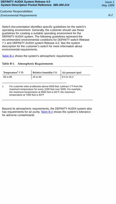
Table B-1 shows the system’s atmospheric requirements.
Beyond its atmospheric requirements, the DEFINITY AUDIX system also has requirements for air purity. Table B-2 shows the system’s tolerance for airborne contaminants
Table B-1. Atmospheric Requirements
Temperature1 (° F)
1. For customer sites at altitudes above 5000 feet, subtract 1°F from the maximum temperature for every 1000 feet over 5000. For example, the maximum temperature at 6000 feet is 84°F; the maximum temperature at 7000 feet is 83°F
Relative humidity (%) Air pressure (psi)
65 to 85 20 to 60 9.4 to 15.2
DEFINITY AUDIX System Release 4.0System Description Pocket Reference 585-300-214
Issue 1May 1999
Customer Responsibilities B-3Cable Connections
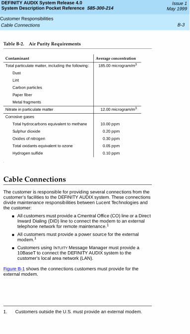
Table B-2. Air Purity Requirements
Cable Connections
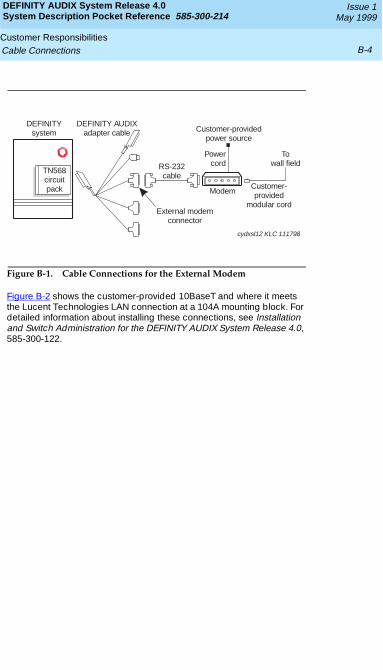
The customer is responsible for providing several connections from the customer’s facilities to the DEFINITY AUDIX system. These connections divide maintenance responsibilities between Lucent Technologies and the customer:
■ All customers must provide a Cmentral Office (CO) line or a Direct Inward Dialing (DID) line to connect the modem to an external telephone network for remote maintenance.1
■ All customers must provide a power source for the external modem.1
■ Customers using INTUITY Message Manager must provide a 10BaseT to connect the DEFINITY AUDIX system to the customer’s local area network (LAN).
Figure B-1 shows the connections customers must provide for the external modem.
Contaminant Average concentration
Total particulate matter, including the following: 185.00 microgram/m3
Dust
Lint
Carbon particles
Paper fiber
Metal fragments
Nitrate in particulate matter 12.00 microgram/m3
Corrosive gases
Total hydrocarbons equivalent to methane 10.00 ppm
Sulphur dioxide 0.20 ppm
Oxides of nitrogen 0.30 ppm
Total oxidants equivalent to ozone 0.05 ppm
Hydrogen sulfide 0.10 ppm
1. Customers outside the U.S. must provide an external modem.
DEFINITY AUDIX System Release 4.0System Description Pocket Reference 585-300-214
Issue 1May 1999
Customer Responsibilities B-4Cable Connections
Figure B-1. Cable Connections for the External Modem
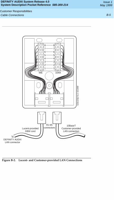
Figure B-2 shows the customer-provided 10BaseT and where it meets the Lucent Technologies LAN connection at a 104A mounting block. For detailed information about installing these connections, see Installation and Switch Administration for the DEFINITY AUDIX System Release 4.0, 585-300-122.
DEFINITY AUDIXadapter cable
RS-232cable
External modemconnector
Customer-providedpower source
Powercord
ModemCustomer-provided
modular cord
Towall field
cydxsl12 KLC 111798
DEFINITYsystem
TN568circuitpack
DEFINITY AUDIX System Release 4.0System Description Pocket Reference 585-300-214
Issue 1May 1999
Customer Responsibilities B-5Cable Connections
Figure B-2. Lucent- and Customer-provided LAN Connections
87654321
87654321
WE 104A
RJ-45connectors
10BaseTCustomer-provided
LAN connectionLucent-provided
D8W cord
h2dx
104p
KLC
021
999
ToDEFINITY AUDIX
LAN connector

DEFINITY AUDIX System Release 4.0System Description Pocket Reference 585-300-214
Issue 1May 1999
Customer Responsibilities
B-6Cable Connections
Abbreviations
AB-1
DEFINITY AUDIX System Release 4.0System Description Pocket Reference 585-300-214
Issue 1May 1999
AbbreviationsA
AC alternating current
ACD automatic call distribution
ADAP administration and data acquisition package
ADU asynchronous data unit
ALT assembly load and test
AMIS Audio Messaging Interchange Specification
API application programming interface
AUDIX Audio Information Exchange
AWG American wire gauge
B
BIOS basic input/output system
bps bits per second
BRI basic rate interface
BSC binary synchronous communications
BTU British thermal unit
C
CCA call classification analysis
CDH call data handler process
CELP code excited linear prediction
CIC customer information center
CICS customer information control system
CL control link
CMC Compact Modular Cabinet
CO central office
COIN central office implemented network
COM1 serial communications port 1
COM2 serial communications port 2
COR class of restriction
COS class of service
DEFINITY AUDIX System Release 4.0System Description Pocket Reference 585-300-214
Issue 1May 1999
Abbreviations
AB-2
CPU central processing unit
CSI called subscriber information
CTS clear to send
D
DAC dial access code
DC direct current
DCE data communications equipment
DCIU data communications interface unit
DCP digital communications protocol
DCS distributed communications system
DID direct inward dialing
DIP data interface process
DMA direct memory access
DNIS dialed number identification service
DOSS Delivery Operations Support System
DS display set
DSP digital signal processor
DSU data service unit
DTE data terminal equipment
DTMF dual tone multifrequency
DTR data terminal ready
E
EIA Electronic Industries Association
ESD electrostatic discharge
ESS electronic switching system
F
F Fahrenheit
FIFO first-in first-out
FOOS facility out of service
FPROMflash programmable read-only memory
DEFINITY AUDIX System Release 4.0System Description Pocket Reference 585-300-214
Issue 1May 1999
Abbreviations
AB-3
G
GBCS Global Business Communications Systems
GOS grade of service
H
Hz hertz
I
IDI isolating data interface
IMAPI INTUITY messaging application programming interface
IMM INTUITY Message Manager
INADS initialization and administration system
I/O input/output
IRQ interrupt request
ISDN integrated services digital network
IVC6 integrated voice CELP card (6 channels)
K
Kbps kilobits per second
KB kilobyte (1024 bytes)
kHz kilohertz
L
LAN local area network
LCD liquid crystal display
LED light-emitting diode
LWC leave word calling
M
m meter
MANOOSmanually out of service
MB megabyte (one million bytes)
DEFINITY AUDIX System Release 4.0System Description Pocket Reference 585-300-214
Issue 1May 1999
Abbreviations
AB-4
MCC Multi-Carrier Cabinet
MHz megahertz
MO magneto-optical
modemmodulator/demodulator
MPDM modular processor data module
ms millisecond
MT maintenance (Lucent INTUITY software component)
MTBF mean time between failures
MWI message-waiting indicator
N
NW INTUITY AUDIX Digital Networking
O
OA&M operations, administration, and maintenance
OS operating system
P
PBX private branch exchange
PC power converter or personal computer
PDM processor data module
PEC price element code
PGATE Processor Gateway
PI Processor Interface
POST power-on self test
ppm parts per million
psi pounds per square inch
R
RAM random-access memory
REN ringer equivalence number
ROM read-only memory
RSC Lucent’s Remote Services Center
DEFINITY AUDIX System Release 4.0System Description Pocket Reference 585-300-214
Issue 1May 1999
Abbreviations
AB-5
RTS request to send
RTU right to use
S
SCC Single-Carrier Cabinet
SCSI small computer systems interface
SID switch integration device
SIMM single in-line memory module
SMSI simplified message service interface
SW switch integration (Lucent INTUITY software component)
T
TDD telecommunications device for the deaf
TDM time division multiplex
T/R tip/ring
TRIP tip/ring input process
TSC Lucent’s Technical Services Center
TTY teletypewriter
U
UCD uniform call distribution
UPS uninterruptible power supply
V
VM INTUITY AUDIX Voice Messaging
VP voice platform (INTUITY software component)
VR INTUITY Intro Voice Response
VROP voice response output process

DEFINITY AUDIX System Release 4.0System Description Pocket Reference 585-300-214
Issue 1May 1999
Abbreviations
AB-6
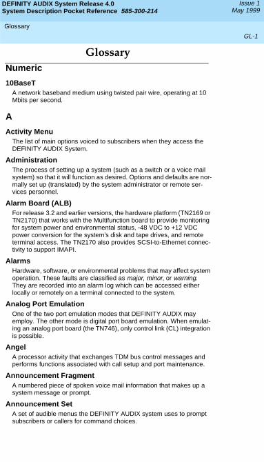
Glossary
GL-1
DEFINITY AUDIX System Release 4.0System Description Pocket Reference 585-300-214
Issue 1May 1999
GlossaryNumeric
10BaseTA network baseband medium using twisted pair wire, operating at 10 Mbits per second.
A
Activity MenuThe list of main options voiced to subscribers when they access the DEFINITY AUDIX System.
AdministrationThe process of setting up a system (such as a switch or a voice mail system) so that it will function as desired. Options and defaults are nor-mally set up (translated) by the system administrator or remote ser-vices personnel.
Alarm Board (ALB)For release 3.2 and earlier versions, the hardware platform (TN2169 or TN2170) that works with the Multifunction board to provide monitoring for system power and environmental status, -48 VDC to +12 VDC power conversion for the system’s disk and tape drives, and remote terminal access. The TN2170 also provides SCSI-to-Ethernet connec-tivity to support IMAPI.
AlarmsHardware, software, or environmental problems that may affect system operation. These faults are classified as major, minor, or warning. They are recorded into an alarm log which can be accessed either locally or remotely on a terminal connected to the system.
Analog Port EmulationOne of the two port emulation modes that DEFINITY AUDIX may employ. The other mode is digital port board emulation. When emulat-ing an analog port board (the TN746), only control link (CL) integration is possible.
AngelA processor activity that exchanges TDM bus control messages and performs functions associated with call setup and port maintenance.
Announcement FragmentA numbered piece of spoken voice mail information that makes up a system message or prompt.
Announcement SetA set of audible menus the DEFINITY AUDIX system uses to prompt subscribers or callers for command choices.
DEFINITY AUDIX System Release 4.0System Description Pocket Reference 585-300-214
Issue 1May 1999
Glossary
GL-2
Asynchronous TransmissionA form of serial communications where each transmitted character is bracketed with a start bit and one or two stop bits.
Asynchronous Data Unit (ADU)A small device that can extend data transmission far beyond recom-mended Electronic Industries Association (EIA) limits over building wir-ing.
Audio Messaging Interchange Specification (AMIS)An analog networking feature that allows subscribers of different voice mail systems to send voice mail messages to one another.
AuditA software program that resolves filesystem incompatibilities and updates restored filesystems to a workable level of service. Audits are done automatically on a periodic basis, or can be performed on demand.
Audio Information Exchange (AUDIX)A complete voice-mail messaging system accessed and operated by touch-tone telephones and integrated with a switch.
AUDIX Administration and Data Acquisition Package (ADAP)
A software package that allows the DEFINITY AUDIX administrator to transfer system subscriber, maintenance, or traffic data over the administration port to a personal computer (PC) or Work Group Sys-tem (WGS).
Automated AttendantA DEFINITY AUDIX feature that allows a customer to set up a main number with a menu of options that routes callers to an appropriate department at the touch of a button.
B
BackupA duplicate copy of a filesystem saved on a removable tape or MO disk. The backup filesystem may be copied back (restored) if the active version is damaged (corrupted) or lost.
BalunOn the DEFINITY AUDIX LAN connection, the adapter needed to con-nect the twisted-pair breakout cable to the coaxial building wire distri-bution system.
Baud RateTransmission signaling speed.
Boot (or Reboot)The operation to start a computer system by loading programs from disk to main memory (part of system initialization).
DEFINITY AUDIX System Release 4.0System Description Pocket Reference 585-300-214
Issue 1May 1999
Glossary
GL-3
Boot FilesystemThe filesystem from which the system loads its initial programs.
Broadcast MessagingA feature that enables the system administrator and other designated users to send a voice mail message to all subscribers automatically.
BufferMemory used to compensate for time differences in transmission by temporarily storing data.
Busyout ServiceWhen a technician or administrator blocks service to keep customers from using faulty equipment until it can be repaired or tested. For instance, when ports (or a link) are busied out, subscribers who try to access their mailboxes hear a fast busy reorder tone. People who would normally reach DEFINITY AUDIX through Call Answering are not forwarded; they hear ringing and no answer at the number they called.
C
Call AnswerA feature that allows the system to answer a call and record a mes-sage when the subscriber is unavailable. Callers may be redirected to the system through the call coverage or Call Forwarding switch fea-tures. Subscribers may record a personal greeting for these callers.
Call Answer Language ChoiceCall answer multilingual option where a user can alternate between a primary language set and a secondary language. The two languages are administered on a per subscriber basis. If this feature is enabled, the subscriber may not use the standard DEFINITY AUDIX Multiple Personal Greetings feature.
Camp-OnA system shutdown option that waits for ports to become idle before blocking service to them. This allows subscribers to finish calls in progress.
Central Office (CO)A main telephone office where private customer lines are terminated and connected to the public network through common carriers.
Central Processing Unit (CPU)The Multifunction board’s main processor that controls system data transfer, input/output (I/O), and logical instructions.
Class of Service (COS)The standard set of features given to subscribers when they are first administered (set up with a voice mailbox).
DEFINITY AUDIX System Release 4.0System Description Pocket Reference 585-300-214
Issue 1May 1999
Glossary
GL-4
Command ModeA system state in DEFINITY AUDIX system releases earlier than 4.0 where flashware is in control and software is shut down. In this state, a technician has access to menu options to see flashware status and ini-tialization history, run through flashware diagnostics, and to start or continue system initialization.
ConfigurationThe particular composition and hardware selected for a system, includ-ing internal options and peripheral equipment.
Control Link (CL)The integration, or interface, between the DEFINITY AUDIX System and the switch that enables the transmission of control messages from the DEFINITY AUDIX System to the switch over a DCIU data link. The control messages are transmitted over a separate cable connection and carry information such as calling-party identification and mes-sage-waiting indicator status and control.
Control Link ModeThe type of switch-link integration for which the DEFINITY AUDIX Sys-tem, R2.0 or later, is connected to the switch via analog-line card emu-lation and a digital connection.
D
Delivery Operations Support System (DOSS) ConfiguratorLucent Technologies’ algorithmic system for configuring products for customers’ specific needs.
Digital Communications Protocol (DCP)An Lucent Technologies proprietary protocol for networking remote communication systems.
DCP Mode 1A Lucent Technologies proprietary Digital Communications Protocol (DCP) connection using a data rate of 56 Kbps for AUDIX Digital Net-working. DCP Mode 1 uses a DS1 facility on the switch or a dedicated facility on the switch or a dedicated facility on a T1 carrier.
DCP Mode 2DCP Mode 2 is an asynchronous, low-speed (9600 or 19,200 bps) connection for AUDIX Digital Networking. DCP Mode 2 uses a modem/data module or modem/Asynchronous Data Unit (ADU) arrangement and connects over analog or voice-grade data lines.
DCP Mode 3A DCP connection using a data rate of 64 Kbps for AUDIX Digital Net-working. DCP Mode 3 uses a DS1 or ISDN facility on the switch or a dedicated facility on a T1 carrier.
DefaultA value that is automatically supplied if no other value is specified.
DEFINITY AUDIX System Release 4.0System Description Pocket Reference 585-300-214
Issue 1May 1999
Glossary
GL-5
Digital-Port (DP) ModeThe type of switch-link integration for which the DEFINITY AUDIX Sys-tem, up through release 3.1, is connected to the switch via digital port board emulation. The type of port board that the DEFINITY AUDIX emulates within the switch (TN754.)
Digital-Port (DP) Board EmulationIn R3.1 and earlier releases, this term referred to both the port emula-tion and to the integration method. In R3.2 and later, it refers to the port emulation only; the integration method can be either control link (CL) or display set (DS).
Digital Signal Processor (DSP)Programmed RAM chips on the Multifunction board that provide signal-ing, power-level control, speech coding, and data processing.
Display Set (DS) IntegrationA new term that replaces the term digital port integration for R3.2 and later. It refers to the use of the display and other messages sent from the switch to the port board for providing voice mail integration with the switch. Integration with the switch is achieved via display set mes-sages. The messages carry information such as calling party identifica-tion and message waiting indicator status and control.
Disconnect Signaling DetectionSignaling from the CO to the PBX which indicates that the far end caller has hung up.
Dual Language GreetingsWhen the Call Answer Language Choice is in effect, the subscriber can record personalized greetings for each of the languages listed as the primary and secondary announcement sets. The subscriber instructs the caller to enter *1 to switch to the alternate language.
E
ErrorsProblems detected by the system during automatic self-tests and recorded in an error log. Errors can produce an alarm (fault) if they exceed a threshold.
EventsOccurrences such as inline errors, maintenance procedure failures, alarms, errors, or transitions into or out of the AUDIX or OA&M states which are recorded in an events log.
F
Faceplate and Alarm Controller (FAC)For release 3.2 and earlier versions, the circuitry on the Multifunction board that monitors activity of the DEFINITY AUDIX System.
DEFINITY AUDIX System Release 4.0System Description Pocket Reference 585-300-214
Issue 1May 1999
Glossary
GL-6
FieldAn area on a form, menu, or report where information can be typed or displayed.
FilesystemsA collection of related files (programs or data) stored on disk that are required to initialize a DEFINITY AUDIX System and provide full ser-vice.
Flash programmable read-only memory (FPROM)Hardware on the TN568 that stores the DEFINITY AUDIX system’s flashware.
FlashwareCode that is stored in flash programmable read-only memory (FPROMs) on the TN568. This programming is retained over power outages but can be reprogrammed automatically on board during ini-tialization.
FormsTerminal screens of information that allow data to be displayed or changed.
GGeneric Tape or Generic Disk
A copy of the standard software and standalone tape utilities (standal-one utilities in Release 4.0) that is shipped with a new system.
Graceful ShutdownTaking the DEFINITY AUDIX System offline (to the maintenance shut-down state) using RESET SYSTEM SHUTDOWN in a camp-on man-ner.
Ground IsolationGround isolation prevents an alternate return current path at the con-necting interface. Return currents pass through the signal wire(s) in the interface connector cable rather than via "green wire ground".
Guest PasswordA feature that allows people who are not subscribers to leave mes-sages on the system by dialing a subscriber's extension and entering a system-wide guest password.
H
Hard Disk DriveThe disk drive the DEFINITY AUDIX system uses to actively save voice messages, personal greetings, subscriber profiles, automated attendants, and other data. The hard disk drive also stores the sys-tem’s AUDIX software.
DEFINITY AUDIX System Release 4.0System Description Pocket Reference 585-300-214
Issue 1May 1999
Glossary
GL-7
HeaderInformation that the system creates to identify a message. A message header includes the originator or recipient, type of message, creation time, and delivery time.
Hunt GroupA group of ports on a switch usually administered to search for avail-able ports in a circular pattern.
I
InitializationThe process of bringing a system to a predetermined operational state. The start-up procedure tests hardware and flashware; loads the boot filesystem programs; locates, mounts, and opens other required file-systems; and starts normal service.
Initialization and Administration System (INADS)A maintenance system used by remote technicians to track alarms.
Interboard Bus
For release 3.2 and earlier versions, the inter-integrated circuit (I2C) bus that provides connectivity between the Alarm board and the Multi-function board.
INTUITY Message ManagerA PC application that is used for the retrieval and display of message headers, addressing to lists, managing personal greetings, and for cre-ating, forwarding, and replying to voice mail messages.
L
Leave Word CallingA switch feature that allows the calling party to leave a standard (non-voice) message for the called party using a feature button or dial access code.
Light Emitting Diode (LED)For Release 3.2 and earlier releases, a red-light indicator on the sys-tem faceplate panel that shows the status of operations and possible fault conditions. An unlit LED indicates a healthy system. When flash-ing, the LED indicates a software problem. When it is steadily lit, a hardware problem exists.Release 4.0 uses three LEDs on the system’s faceplate to report the system’s status and to provide alarm and diagnostic information.
Liquid Crystal Display (LCD)For release 3.2 and earlier releases, the 10-character alphanumeric display on the DEFINITY AUDIX faceplate panel that automatically shows status of the system including alarms.
DEFINITY AUDIX System Release 4.0System Description Pocket Reference 585-300-214
Issue 1May 1999
Glossary
GL-8
Local Area Network (LAN)A short distance data communications network used to link computers and peripheral devices under some form of standard control
Local Maintenance Terminal (LMT)A display terminal located near the DEFINITY AUDIX System and the switch. It is temporarily attached to the DEFINITY AUDIX during an on-site service visit.
LoginA unique code used to gain approved access to a subscriber’s voice mailbox or to a display terminal.
M
Magneto-optical (MO) Disk DriveWith release 4.0, the device used to store nightly and weekly backups of customer data, install new software releases, restore the system and remove core dumps and other maintenance information. The drive stores information on an MO disk. The MO drive replaces the tape drive from previous releases.
MailboxA portion of disk memory given to each subscriber for creating and storing outgoing and incoming messages.
Message-Waiting LampAn LED on a telephone that alerts subscribers to new messages.
MO DiskWith release 4.0, the storage medium used by the magneto-optical disk drive to store backups and other information.
ModemA modulator/demodulator used for transmitting analog signals across phone lines.
Multifunction Board (MFB)For release 3.2 and earlier releases, the hardware platform (TN566B, 386 version and TN567, 486 version) which holds the central process-ing unit, controllers, memory devices, and signal processors that make a DEFINITY AUDIX System operational. For release 4.0 the TN568 is the only circuit pack and therefore performs all operations for the DEFINITY AUDIX system.
Multilingual SystemA DEFINITY AUDIX System containing primary and secondary lan-guage announcement sets. A large (40 hour) system can hold up to nine different language sets. The Telecommunications Device for the Deaf (TDD)-based announcement set is treated as a multilingual option.
DEFINITY AUDIX System Release 4.0System Description Pocket Reference 585-300-214
Issue 1May 1999
Glossary
GL-9
N
Native ModeThe ability of the switch to recognize the DEFINITY AUDIX as a DEFINITY AUDIX circuit pack. With native mode support, the switch reserves five slots for the DEFINITY AUDIX 3.2 assembly, and two slots for the DEFINITY AUDIX 4.0. Additionally the switch is able to correctly identify the DEFINITY AUDIX board in alarms sent to the ser-vices organization.
Non-native ModeWithout native mode, the MFB or TN568 slot is provisioned as a TN754, TN2181 or TN746B, the five slots occupied by the DEFINITY AUDIX 3.2 assembly or two slots occupied by the DEFINITY AUDIX 4.0 are not reserved, and alarms are reported as alarms for a TN754, TN2181, or TN746B.
Nonvolatile Random Access Memory (NVRAM)A battery-backed RAM on the Multifunction board that retains data through loss of power.
Null Modem CableA cable that transposes transmit and receive leads on an RS-232 con-nection.
O
Operating System (OS)The set of programs that runs the hardware and interprets software commands.
Operations, Administration, and Maintenance (OA&M)A state of system operation where core processes of the Multifunction board are accessed, including system initialization, resource configura-tion, forms interface, entry into the maintenance subsystem, and file-system access. Also entered when customer data must be restored.
OutcallingA feature that allows the system to dial subscribers’ numbers or go to pagers to inform them they have new messages.
P
PortA connection or link between two devices, allowing information to travel through it to a desired location. For example, a switch port con-nects to a DEFINITY AUDIX port to allow a subscriber on a voice ter-minal to leave a message.
DEFINITY AUDIX System Release 4.0System Description Pocket Reference 585-300-214
Issue 1May 1999
Glossary
GL-10
ProtocolA set of specific rules, procedures, or conventions relating to forms and timing of data transmission between two devices.
R
RebootA system reboot is done to clear major system problems (such as cor-rupt program memory). It also runs automatically whenever the system is powered up. Also see boot.
Remote Field UpdateA set of software changes on a given release that is transmitted from a central location to customer equipment. Changes are generally restricted to serious bug fixes and are limited in volume.
Reply Loop EscapeAllows the subscriber the option to return to responding to a message after trying to reply to a non-subscriber message.
RestartDuring maintenance, a system restart brings the system software back into full service, usually after an administrative shutdown. This is often done to try to clear software problems.
RISCReduced Instruction Set Computer. Refers to computers based on an unusually high speed processing technology that uses a far simpler set of operating commands.
S
Sanity and Control Interface (SAKI)An integrated circuit that receives and transmits TDM bus control mes-sages and monitors the sanity of the angel processor.
Shutdown StatesStates of system operation where either a technician can shut down the system for maintenance, or where a critical error condition brings down the system. In either case, filesystems are closed and the sys-tem can be powered down and removed from the carrier.
Small Computer Systems Interface (SCSI)An interface standard defining the physical, logical, and electrical con-nections to computer system peripherals such as tape, magneto-opti-cal and disk drives.
DEFINITY AUDIX System Release 4.0System Description Pocket Reference 585-300-214
Issue 1May 1999
Glossary
GL-11
Standalone UtilityA software utility with options that include disk drive initialization, copy-ing files from a generic tape or MO disk onto the customer’s disk, and map partition modification. With release 3.2 and earlier releases the standalone utilities where referred to as standalone tape utilities.
Subscriber Specific Announcement SetWhen the Multilingual feature is enabled, each subscriber form has three fields specifying the announcement set with which the subscriber will interact with the system once they log in, and the two announce-ment sets with which callers to the subscriber’s mailbox can interact with the system.
T
Transmission Control Protocol/Internet Protocol (TCP/IP)A set of protocol standards which allows a process on one machine to send data to a process on another machine. Communication may be full or half duplex. TCP/IP includes support for multiple operating sys-tems and machine architectures.
Telecommunications Device for the Deaf (TDD)A category of DEFINITY AUDIX features, including personal greetings and announcement sets, that exchange text messages with subscrib-ers or callers using teletypewriters.
Teletypewriter (TTY)A device that uses Baudot tones to transmit text-based telephone mes-sages for the hearing impaired. Subscribers or callers can use tele-typewriters to access the DEFINITY AUDIX system if TDD features are enabled.
Time Division Multiplex (TDM) BusThe interface between the DEFINITY AUDIX System and the switch that carries digitally-encoded voice waveforms and circuit-switched data.
U
UpdateA limited incremental change on an existing release involving software only.
UpgradeThe replacement of one release with a new release. This may involve software, flashware, hardware, and/or data.
DEFINITY AUDIX System Release 4.0System Description Pocket Reference 585-300-214
Issue 1May 1999
Glossary
GL-12
V
Voice PortAn electrical pathway that connects calls between two devices, such as telephones, switches, or voice messaging systems.
DEFINITY AUDIX System Release 4.0System Description Pocket Reference 585-300-214
Issue 1May 1999
Index
IN-1
Index
Numerics
10BaseT, B-4
A
Administration and Data Acquisition Package (ADAP), 1-1, 1-4
alarm board, A-1alarm relay, A-5alarms
non-native mode, 1-6AMIS Analog Networking, see
Audio Messaging Inter-change Specification Analog Networking
analog port emulation, A-6Audio Messaging Inter-
change Specification (AMIS) Analog Networking, 2-3
voice ports, 3-4Automated Attendant, see
features, Automated Atten-dant
B
Broadcast Messaging, see features, Broadcast Mes-saging
C
cable connections, B-3 to B-5capacity, 3-1 to 3-6CELP, see code-excited linear
predicationcircuit packs
TN2181, 1-5 to 1-6, 2-2, A-2
TN566, A-1TN567, A-1TN568, 1-5, 2-2, A-1TN746, A-6TN754, 1-5 to 1-6, 2-2
code-excited linear predica-tion (CELP), 1-1, 2-4
Compact Modular Cabinet (CMC), see switches, com-patible; requirements, space, in a CMC
configurator, see DOSS con-figurator
control link integration, see switch integration
customer responsibilities, B-1 to B-5
D
DCS Networking, A-6DEFINITY AUDIX system
releases earlier than 4.0, see releases earlier than 4.0
DEFINTIY AUDIX systemrequired staff, B-1
Digital Networking, 2-3 to 2-6advantages, 2-4connectivity
DCP Mode 1, 2-5DCP Mode 2, 2-6DCP Mode 3, 2-5
high-speed, 2-4 to 2-5low-speed, 2-5 to 2-6remote nodes, 2-4
DCP Mode 2, 2-6RS-232 Asynchronous,
see DCP Mode 2traffic guidelines, 2-4, 2-6,
A-3voice ports, 2-4, 3-4
digital port emulation, 1-5 to 1-6, 2-2
digital set emulation, see set-type emulation
display set integration, see switch integration
DOSS configurator, 3-3
DEFINITY AUDIX System Release 4.0System Description Pocket Reference 585-300-214
Issue 1May 1999
Index
IN-2
E
electromagnetic interference, 2-9
Erlangs, 3-1 to 3-3
F
faceplate, 2-8 to 2-9features
Alarm Origination, 1-4, A-4 to A-5
announcement setslimits, 1-1Telecommunications
Device for the Deaf (TDD), 3-5
voice storage, 3-4 to 3-5
Automated Attendantvoice ports, 3-3
Broadcast Messagingvoice ports, 3-3
for the customer organization, 1-1 to 1-2
Multilingual, see also fea-tures, announcment sets, 3-4 to 3-5
Outcalling, 1-3voice ports, 3-3
overview, 1-1 to 1-4for the
subscriber, 1-2 to 1-3for the system
administrator, 1-3Traffic Reports, 1-4
flash programmable read-only memory (FPROMs), 2-2
flashware, 2-2FPROMS, see flash program-
mable read-only memory
G
Grade of Service, 3-1 to 3-3
H
hard disk drive, see also voice storage, 2-2
I
implementation, B-1INTUITY Message Manager
benefits, 1-3capacity, 3-5 to 3-6
L
LCD, see liquid crystal displayliquid crystal display
(LCD), A-5local area network (LAN) con-
nections, see 10BaseT
M
magneto-optical (MO) disk drive, 2-7, A-5
limitations, 3-6maintenance buttons, see
recessed maintenance but-tons
maintenance modem, A-4connections, B-3
MO disk, see also mag-neto-optical disk drive, 2-7
multifunction board, A-1Multilingual, see features,
Multilingual
N
native mode, 1-5 to 1-6switch support, A-1 to A-2
non-native mode, see native mode
O
Outcalling, see features, Out-calling
DEFINITY AUDIX System Release 4.0System Description Pocket Reference 585-300-214
Issue 1May 1999
Index
IN-3
P
port board emulation, see dig-ital port emulation; analog port emulation
port slots, 1-2power cables, 2-9ProLogix, see switches, com-
patible; requirements, space, in a CMC
R
releases earlier than 4.0, A-1 to A-7
requirementsenvironmental, 2-12 to 2-
13, B-1 to B-3power, 2-12space, 2-9 to 2-12
benefits, 1-2, A-1in a CMC, 2-9, A-1in an MCC, 2-9in an SCC, 2-9
RS-232 Asynchronous, see Digital Networking, DCP Mode 2
S
SCSI cables, 2-9set-type emulation, 2-3slots, see port slots, 1-2software, 2-2, 2-3staff, see DEFINITY AUDIX
system, required staffsubscribers
limits, 1-1DCP Mode 2, 2-6high-speed Digital
Networking, 2-4switch integration, A-6switches
compatible, 1-4, 1-7considerations, 1-5native mode, 1-7
T
tape drive, A-5Telecommunications Device
for the Deaf (TDD) announcement set, see fea-tures, announcment sets, Telecommunications Device for the Deaf
TN2181, see circuit packs, TN2181
TN568, see circuit packs, TN568
TN746, see circuit packs, TN746
TN754, see circuit packs, TN754
Traffic Reports, see features, Traffic Reports
U
universal port slots, see port slots, 1-2
V
voice portsadministration, 1-5,
A-2 to A-3changes for Release
4.0, A-2configuration, 3-1 to 3-4migrations, A-3
voice ports, see also Audio Messaging Interchange Specification Analog Net-working; Digital Networking; features, Automated Atten-dant; features, Broadcast Messaging; features, Out-calling
voice storageavailable increments, 2-2limits, 1-1, 2-2
voice storage, see also hard disk drive; features, announcement sets, voice storage

DEFINITY AUDIX System Release 4.0System Description Pocket Reference 585-300-214
Issue 1May 1999
Index
IN-4