Defense Technical Information Center Compilation Part Notice · X-SAR/SRTM is Germany's and Italy's...
12
UNCLASSIFIED Defense Technical Information Center Compilation Part Notice ADPO10830 TITLE: X-SAR/SRTM. Part of a Global Earth Mapping Mission DISTRIBUTION: Approved for public release, distribution unlimited Availability: Document partially illegible. This paper is part of the following report: TITLE: Space-Based Observation Technology To order the complete compilation report, use: ADA391327 The component part is provided here to allow users access to individually authored sections f proceedings, annals, symposia, ect. However, the component should be considered within he context of the overall compilation report and not as a stand-alone technical report. The following component part numbers comprise the compilation report: ADPO10816 thru ADPO10842 UNCLASSIFIED
Transcript of Defense Technical Information Center Compilation Part Notice · X-SAR/SRTM is Germany's and Italy's...

UNCLASSIFIED
Defense Technical Information CenterCompilation Part Notice
ADPO10830TITLE: X-SAR/SRTM. Part of a Global Earth Mapping
Mission
DISTRIBUTION: Approved for public release, distribution unlimited
Availability: Document partially illegible.
This paper is part of the following report:
TITLE: Space-Based Observation Technology
To order the complete compilation report, use: ADA391327
The component part is provided here to allow users access to individually authored sections
f proceedings, annals, symposia, ect. However, the component should be considered within
he context of the overall compilation report and not as a stand-alone technical report.
The following component part numbers comprise the compilation report:
ADPO10816 thru ADPO10842
UNCLASSIFIED

32-1
X-SAR/SRTMPart of a Global Earth Mapping Mission
Wolfgang KEYDEL,David HOUNAM, Regina PAC, Marian WERNER
Institut ftir Hochfrequenztechnik & RadarsystemeDLR Oberpfaffenhofen
82234 Wessling - GermanyTelephone: +49 8153 28 23 05
Fax: +49 8153 28 11 35e-mail: [email protected]
Abstract (IFSAR's) to acquire data over 80% of Earth's
X-SAR/SRTM is Germany's and Italy's land mass (between 60'N and 56°S) and produce
contribution to the Shuttle Radar Topography topographic products which meet Interferometric
Mission (SRTM), which has been operated from Terrain Height Data (ITHD), specifications: 30 m
February 12th 2000 to February 21st 2000. It is the x 30 m spatial posting with •<16 m absolute vertical
X-Band radar interferometer. which operated in linear accuracy and •_20 m absolute horizontalunison with SIR-C the C-Band interferometer of circular accuracy at 90%.
the US. Both technique and technology of The C-Band Radar-Interferometer was an US-X-SAR/SRTM will be described as well as both Instrument, and the X-Band Radar-Interferometerthe internal and external calibration procedures. X-SAR was Germany's and Italy's contribution toThe error sources which influence the product SRTM with DLR as the project lead responsiblequality will be shown as well as first X-SAR for system engineering, mission operation,results. calibration and data processing, Dornier Satellite
Systems GmbH now renamed to ASTRION1.Introduction Co.was the main contractor for the development ofThe Shuttle Radar Topography Mission (SRTM) the X-SAR flight instrument (X-SAR/SRTM).has been launched on February 2 2000 with the Fig.1 shows both the C-SAR and the X-SARSpace Shuttle Endevour (STS-99). The 13,6 tons ofof 2intrfermetic rdar coverage obtained during the eleven day mission.the payload consisting of 2 interferometric radar (The colored Fig's I - 4 and 7 - 10 are in chap 9).systems, a C-Band and a X-Band radar, orbited andmapped the Earth for 11 days. The whole mission 2. The Shuttle Radar Topography Missionmainly was sponsored from the US National 1, 2, 4,5, 61Imaging and Mapping Agency(NIMA) as well asfrom the Italian Space Agency (ASI) and the The two-frequency (C-band and X-band) single-German Aerospace Centre DLR. [1 to 6] The pass interferometric SAR's (Synthetic ApertureMission Objectives were to use C-band and Radar) instrument were configured byX-band interferometric synthetic aperture radar's simultaneously operating two sets of radar
Main mission characteristics
Orbital altitude 233,1 km,Inclination 57,0 "Flight duration 11 days, 166 revsFlight attitude (roll, pitch, yaw) 3010, 180 0, 0 0, ± 0,1 0,
Total payload weight 13405 kgTotal payload power/energy 7,14 kW, 9,8 kW peak/88OkWhNumber of data tapes 320 equivalent to 2140 GByteCrew members G.Thiele, J.Kavandi, M.Mohri, K.Kregel, D.L.P.Gorie
Paper presented at the RTO SET Symposium on "Space-Based Observation Technology",held on the Island of Samos, Greece, 16-18 October 2000, and published in RTO MP-61.
32-2
antennas, each with a transmit/receive and a power, but since the coverage of sites with bothreceive-only antenna separated by a 60 m baseline frequencies was desirable, the basic plan took thisand two receiver channels. The 12 meter long and power usage into account. The advantage is the40 centimeter wide X-SAR main antenna for ability to crosscheck the maps produced by thetransmit and receive (channel one) was mounted two systems.directly to a tiltable part of the 12 meter C-radarantenna truss structure in the shuttle's cargo bay. The primary antenna could be tilted in elevation toThe second (receive-only) antenna was 6 meter align its beam with the one of the secondary
long and was, together with the second 8 meter antenna. To accomplish an azimuth in-orbitlong C-band antenna, mounted onto the tip of a 60 alignment of both antennas an electronic beam
meter long, deployable, stiff, boom structure steering of the receive antenna within a range of
perpendicular to the velocity direction of the space 0,9 degrees in steps of 0.3 degrees has been
shuttle, to build the baseline. That configuration, installed. However, it was not necessary to use this
the space shuttle with its 60-meter mast extended equipment during the mission.from the cargo bay was the longest structure ever The two-channel output data streams, with 90flown in space. Mbit/sec, produced by the X-SAR radar were
Fig.2 shows that schematically, Fig 3 shows a multiplexed for recording on cassette tapephotograph of the deployed mast with both recorders onboard or down linked at half the rate.antennas at the end. These represent the raw amplitude and phase data
for the two images to be processed to create the3. X-SAR as Part of SRTM, .[ 1,, 5, 6] interferometric fringes on ground after the mission.Fig.4 shows the joint operation modes of both For X-SAR alone more than 80 hours of data takessystems principally. X-SAR was not capable of have been recorded on 110 cassette tapes.operating in a ScanSAR mode like the C-radarwhich would also allow complete coverage of the The X-SAR operated in a higher-resolution modeEarth during the short orbiting period of 11 days or but with a smaller swath width of 50 km than the166 orbits. X-SAR operated, in turn, in a higher- C-Band radar. Only approximately 40% of theresolution mode with a smaller swath width of surface being flown over have been detected.approximately 50 km placed inside the 250kmi Consequently the selection of the reference targetSIR-C scan swath at an angle of 54.5 degrees off- locations is determined by the illuminated swathsnadir. The C.band and X-band could operate of the X-SAR-System. The locations are positionedsimultaneously or independently. For the most in regions of swath crossing points. Thus everypart, they operated together. The only disadvantage reference target generally appears in two differentto that was that joint operations consumed more SAR images.
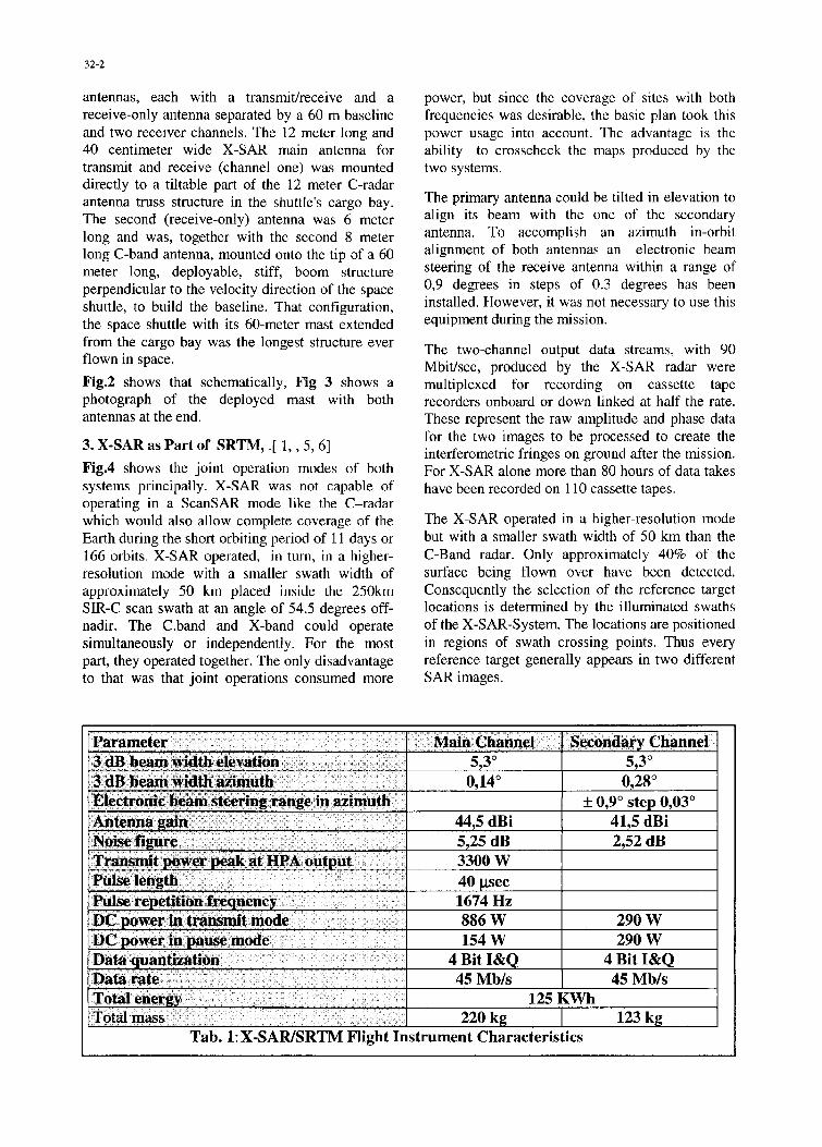
Parameter _____ Main Channel Secondary Channel3 dB beam width elevation •... 5,30 5,303 dB beam width azimuth 0,140 0,28°Electronic beam steering range in azimuth +0,9' step 0,03'Antenna gain 44,5 dBi 41,5 dBiNoise figure 5,25 dB 2,52 dBTransmit power peak at HIPA output 3300 WPulse length 40 psecPulse repetition frequency 1674 HzDC power in transmit mode 886 W 290 WDC power in pause mode 154 W 290 WData quantization 4 Bit I&Q 4 Bit I&QData rate 45 Mb/s 45 Mb/sTotal energy 125 KWhTotal mass 220 kg 1 123 kg
Tab. 1: X-SAR/SRTM Flight Instrument Characteristics

32-3
X-Band X-Band C-Band C-BandPrimary Secondary Primary Secondary
Frequency 9.6 GHz 9.6 GHz 5.3 GHz 5.3 GHzPolarization VW V H, V H, VPolarization Isolation 39 dB >25 dB >25 dBAdjustable Off-Nadir Angle 150 - 55 0 540 -55° 150 - 55 0 150 - 550
mechanical mechanical electronical electronicallyOff Nadir during Mission 54.50 55.50 36.5', 46.5', 36.50, 46.5',
530, 580 530, 580
Adjustable Horizontal Angle 0' 0.90 step 0.3'Swath Width 45 km 45 km 225 km 225 kmAzimuth Res. (4 looks) 25 m 25m 30m 30mRange Resolution10 MHz/20 MHz Bandwidth 20m/10m 20 m / 10 m 25 m/ 13 m 25 m/ 13 mTotal Dynamic Range 60 dB 60 dB 60 dB 60 dBRadiated Peak Power 3.5 kW 1.7 kWMain Antenna Area 0.4 m x 12 m 0.4m x 6m 0.7 m x 12 0.7m x 8mMain Antenna Gain 43.5 dB 41,8 dB 42.8 dB 40,0 dBElevation Side Lobe -20 dB -21 dB -18 dB -19 dB3 dB Beam Elevat. /Azimuth 5.50 / 0.140 5,30/0,280 4.90 / 0.250 4,9c/37,50
Radiometric Resolution 2.5 dB 2.5 dB 1.5 dB 1.5 dBData Rate / Channel 45 Mb /sec 45 Mb /sec 45 Mb /sec Mb /sec
Tab.2 Comparison of X-Band and C-Band flight instruments
4. The Calibration [1, 5, 8] Hence, in the area from Bayreuth down to Fissen
The accuracy requirements for the mission results in Bavaria, a calibration field was set up
claim for an extremely accurate system calibration, encompassing 27 different locations, in which
In total the SRTM calibration is divided into 5 passive as well as active reference targets (trihedral
phases: comer reflectors and/or transponder) and calibratedground receivers were erected. By using the
1. Preflight concept definition phase including ground receivers and the transponders, the antennasensor characterization, calibration algorithm patterns of both the German-Italian X-SAR-Systemdevelopment and implementation and the American SIR-C-Radar could be measured,
2. Ground campaigns during the mission which is required for radiometric calibration. Thecorner reflectors serve as reference points in the
3. On board calibration measurements during the topographic data to calibrate the phase.mission
4. A 6 to 8 month's commissioning phase for the Some comer reflectors had to be moved between
generation of static and dynamic calibration passes. All had to be pointed towards the shuttle
files, and for analysis and modeling of before a pass. Furthermore, it was necessary to
parameter drifts with temperature and time determine the geographical location of everywhich is the present status corner site very precisely by using differential
GPS.5. Operational calibration and validation after the
commissioning phase which will be started at The interferometric calibration concept for X-SAR
the beginning of next year considers instrument phase calibration and InSAR(Interferometric SAR) imaging geometry
The task of the on-ground calibration was to set up calibration also. A height error may result fromprecisely surveyed control targets for both the errors due to uncertainties in the imaging geometryradiometric and interferometric calibration, 22 parameters, such as baseline length and tilt angle.calibration fields distributed all over the world and orbit data, and from phase variations caused byhave been established, the instrument. The tables in Fig 5 (following page)

32-4
X-SARISRTM Error BudgetX-SAR/SRTM Height Error Sources
-Baseline Tilt Angle Error Atmospheric Error Performance Requirements:
-Baseline Length Error • Position Error
-Instrument Phase Error Calibration Error - Relative Height Accuracy (90 %) < 6 m
-Random Phase Error Slant Range Error • Absolute Height Accuracy (90 %)< 16 m
-Ambiguity Phase Error Processing Error
Hei ht Error Examples (Middle of Swath)Relative (30 seconds) Absolute (11-days)
Error Type Accuracy Error Accuracy ErrorBaseline Tilt Angle 2 arcsec 3,0 m 9 arcsec 13,4 mBaseline 1,3 mm 0,8 m 4,0 mm 2,6 mInstrument Phase 4,0 deg 4,2 m 4,0 deg 4,2 mTotal (RSS) 5,5 m 14,4 m
Fig.5 Error Sources and examples of height errors resulting from special error types
Deutsches Zentrum fir Luft- und Raumfahrt e.V.
Calibration Concept
*Estimation of systematic errors*Monitoring of system parameters and instrument performance*Characterization of instrument parameters*Development of calibration models (parameter drifts as a function oftime and temperature)-Ocean as reference height (sea surface height model)
r Known orbit with respect to WGS 84 ellipsoid
O cean Sea Mleasured heightI
G round_,_
Level Control I Ocean SeaCalibration l LeveliCalibration
Fig. 6 Scheme of calibration concept

32-5
list the main error sources as well as the accuracy The complex SRTM data processing will requirerequirements which had to be fulfilled in order to one to two years in order to convert the raw radarreach the goals of the mission with respect to data into topographic maps. Resulting data formatsX-Band. A suite of sensors was responsible for will be compatible with standard cartographic data-measuring and controlling the proper alignment of analysis software and tailored to the needs of thethe secondary antenna with respect to the main scientific, commercial and operational userantenna and the attitude and position of the communities.interferometric system in orbit. Detailed specifications of the X- and C-bandA star tracker has measured the orientation of the derived DEM's and other elevation products areinterferometric system in orbit, which is supported delineated in the box on top of the next page. Apartby an inertial reference unit consisting of three 2- from digital terrain height maps in two differentaxis gyros. An optical tracker of the secondary resolutions, there are multi-look images in groundantenna which is a video camera and LED targets, range, single look images in slant range as well aswill allow a relative 3-axis measurement of the terrain-corrected data and incidence angle masks.boom antennas. Additionally, GPS antennas on the A height error map co registered to the elevationsecondary antenna structure will provide a 0.8m maps will be available indicating the quality of theorbital position accuracy determination and, interferometric DEM's pixel by pixel.furthermore, a time reference for the radar with anaccuracy of 100 microsec. In addition to the static The measurement of topography in vegetatedmisalignments, there is the dynamic reaction of the regions through SAR techniques causes in some
top of the boom to the space shuttle orbit and areas deviations from the trne terrain heightattitude control system and thermal displacements. because the short radar wavelengths of C- and X-An extremely stiff and thermal stable construction band (5.3cm and 3.1cm, respectively) sense theis foreseen using CRFP (Carbon Re-inforced Fiber very top of dense canopies or high buildings. InPlastic) technology The ocean surface serves as order to correct for these inconsistencies within thereference height. Before and after each continental DEM, it is planned to provide a land cover
pass, there was a calibration over the ocean (Fig. 6, classification map.previous page ). Phase calibration has to beperformed for time and temperature variations. 6. Results [1,3,5]Preflight characterization of the behavior of critical During the 11 day mission 69 data takes have beenparts is required for estimating the residual received and analyzed during mission with72calibration error. In certain cases these parameters Gigabytes of data, 99 interferogram's and 45in combination with temperature measurements DEM's have been generated. The InSARcan be sufficient for later correction. processing of a 45 km x 170 km area took 1 hour.
The processing was done on a 12 CPU SUN5. Products, [1,3,5] E4000.
The final products of the SRTM mission are digital Fig .7 shows as the very first result obtained 11elevation products in a mosaic format generated hours after launch the interferometry fringes asfrom C- and X-band radar frequencies. X-band full well as the resulting (DEM) of an area aroundcoverage begins at latitudes greater than about 550 White Sands in New Mexico, United States. TheNorth/South. The C-band radar has completely DEM is color coded following the rules of normalcover the land surface between 600 North and 58' geographic maps, i.e. increasing altitudes fromSouth with multiple overlap in the higher latitudes. light brown over dark brown up to white.
SRTM Data Produkts
DTED (Digital Terrain Elevation Data) => ITED (Interferometric Terrain Elevation Data)
* 1 degree x 1 degree cell; origin in SW cornera elevations in meter* intervals in Arc Seconds (DTED 1: posts every 3 arcsec, DTED 2: 1 arcsec)* datum: vertical = mean sea level, horizontal = WGS 84* Specification ITED level 2
C-lkand X-Band
horizontal absolute accuracy < 20 m < 15 m ( 90% circular error WGS)vertical absolute accuracy < 16 m < 10 m ( 90% linear error WGS)

32-6
The Fig 8 and Fig 9 show exemplary a DEM ofparts of Hokkaido, the northernmost of the fourmain islands of Japan. With an area 83.500 squarekilometers it constitutes more than 20 percent ofJapan's land area and comprises 90 percent ofJapan's pastureland. The scene shows the northernand southern shores of Ushiura-wan (VolcanoBay). A distinctive feature is the volcano Komaga-take just off the image center on the southern shoreof Ushiura-wan. The lower image in Fig. 9 shows athree dimensional representation of the Komagavolcano.
Fig. 10 shows in the upper image a X-SAR DEMas a perspective view over the Baia deParanagua/Brazil with the Pico Parana in theupper left and in the lower image a photograph ofthat mountain.
7. Concluding Remarks
The whole Mission was successful and fulfilled theexpectations up to 99.6%. The quality of the binarydata as well as their homogeneity seems to beexcellent [3], however, the final data quality cannot yet be accomplished due to missing precisionattitude and orbit data The system and theprocessor as well presently deliver the expectedparameters close to the theoretical limits.
8. References
[ 1] DLR/DFD Homepagehttp://www.dfd.dlr.de/srtrn/
[2] JPL Homepage: http://www.ipl.nasa.gov/srtm/
3] Eineder, M.,R.Bamler, N.Adam, H.Breit,S.Suchandt, U.Steinbrecher: SRTMIX-SARInterferometric Processing-First Results, EUSAR2000, 3rd European Conference on SyntheticAperture Radar, 23 - 25 Mai 2000, Munich,Germany,pp 233 -236
[ 4] T. Farr and M. Kobrick, "The ShuttleRadarTopography Mission: A Global DEM",IGARSS Proceedings 2000.
[ 5] Werner, M. Shuttle Radar Topography Mission(SRTM)-Mission Overview, Proc. EUSAR 2000,3 rd European Conference on Synthetic ApertureRadar, 23 - 25 Mai 2000, Munich,Germany,pp.209 - 212
[ 6] Werner, Marian, Kay-Bodo Klein, MartinHaeusler. Performance of the Shuttle RadarTopography Mission, X-Band Radar System
[ 7] WERNER, Marian, Operating the X-band SARInterferometer of the SRTM
[ 8] Zink, M., D.Geudtner: First Results from TheCalibration of the Interferometric X-SAR Systemon SRTM, EUSAR 2000, 3" European Conferenceon Synthetic Aperture Radar, 23 - 25 Mai 2000,p 223

32-7
-t.~d 24-FIM-100 1&ýW OMTC/fl 0/11:30M.0 1~ 01=10O0I
Fig. I Coverage Map- X-SARJSRTM coverage during the II 1day shuttle mission. The Internet linkhttp://isis.dlr.de/XSAR/'srtm will guide you to the geographic locations of the X-SAR swathS.[5. 71
Figure 2: Drawing of the SRTM Configuration with the Secondary Antennas mounted on the Mast

32-8
Fig. 3 Photography of the SRTM Mast with outboard antennas, Courtesy JPL [2, 41
ibrnbV d C' cdinr t, S
ylI
45
CC
L,-V k C tr
Fig. Schme f SRM Ocraton, he lhpsidsreprsenttheC Bad sAngletesthe -4A wt slctd rud5 0lo ngeCuts L1,4

SRTM/XoSAR DEM White Sands, New Mexico, USA
rr
Fig. 7 Fringes, SAR-Image, colorcoded DEM of White Sands, New Mexico, map in theupper right corner I 1
Fig. 8 DEM of Hokkaido Peninsula, Japan, with interferomnetry fringes with map, enlargedDIEM of Kanaka-take Volkano [ 1]

32-10
Fig. 9 :Kanaka-take Volkano, Hokkaido Japan: Fringes (upper left), error residua (upper right),3-D representation (bottom) 1 3, 1]

32-11
Data are recorded over te Bala d•Tharanagw i BraziI, appr ihnaely2E0kin sou h-east of S~ o Paulolocaed in the State of ParamfiFurther inland the highest peak ofth Se ra d Nar Range• the b~c•
P~r•A{•22•)is visible on the
Parawagun i s an estir ry reachingS4Okm nlad and compriS. rae 67m.atoal
SU~tpper image : er pective view
S~~~~crea ed from theoY: WiS............ o ve~r the Baja de Paranagof
Stowands the 1110 ntains ,in Wh W.st•i Lower image: photograph of Pieo
Para na.
D Tke. <24 •.t