Deep-Ripping and Decompaction Ripping and Decompaction practice, ... The two-phase application of 1)...
14
DEPARTMENT OF ENVIRONMENTAL CONSERVATION New York State Deep-Ripping and Decompaction New York State Department of Environmental Conservation Division of Water April 2008
Transcript of Deep-Ripping and Decompaction Ripping and Decompaction practice, ... The two-phase application of 1)...

DEPARTMENT OF ENVIRONMENTAL CONSERVATIONNew York State
Deep-Ripping andDecompaction
New York State Department of Environmental Conservation
Division of Water
April 2008

Document Prepared by: John E. Lacey, Land Resource Consultant and Environmental Compliance Monitor (Formerly with the Division of Agricultural Protection and Development Services, NYS Dept. of Agriculture & Markets)
1
Alternative Stormwater Management Deep‐Ripping and Decompaction
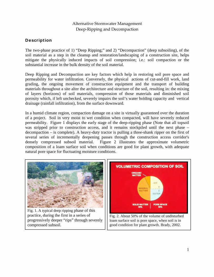
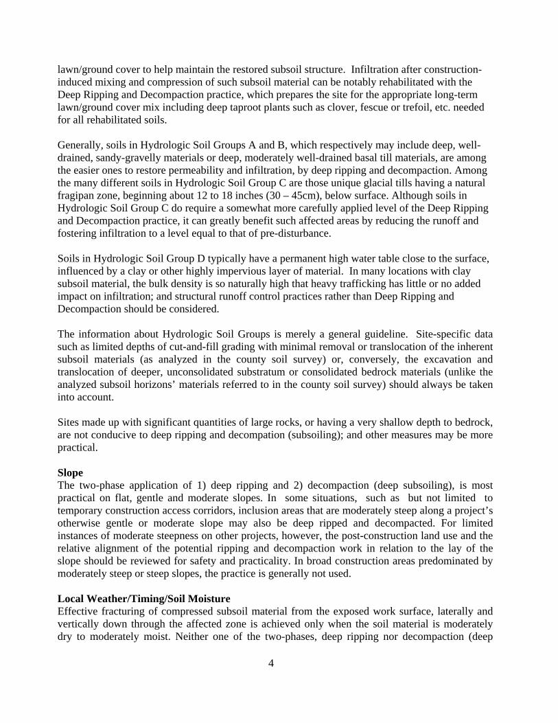
Description The two-phase practice of 1) “Deep Ripping;” and 2) “Decompaction” (deep subsoiling), of the soil material as a step in the cleanup and restoration/landscaping of a construction site, helps mitigate the physically induced impacts of soil compression; i.e.: soil compaction or the substantial increase in the bulk density of the soil material. Deep Ripping and Decompaction are key factors which help in restoring soil pore space and permeability for water infiltration. Conversely, the physical actions of cut-and-fill work, land grading, the ongoing movement of construction equipment and the transport of building materials throughout a site alter the architecture and structure of the soil, resulting in: the mixing of layers (horizons) of soil materials, compression of those materials and diminished soil porosity which, if left unchecked, severely impairs the soil’s water holding capacity and vertical drainage (rainfall infiltration), from the surface downward. In a humid climate region, compaction damage on a site is virtually guaranteed over the duration of a project. Soil in very moist to wet condition when compacted, will have severely reduced permeability. Figure 1 displays the early stage of the deep-ripping phase (Note that all topsoil was stripped prior to construction access, and it remains stockpiled until the next phase – decompaction – is complete). A heavy-duty tractor is pulling a three-shank ripper on the first of several series of incrementally deepening passes through the construction access corridor's densely compressed subsoil material. Figure 2 illustrates the approximate volumetric composition of a loam surface soil when conditions are good for plant growth, with adequate natural pore space for fluctuating moisture conditions.
Fig. 1. A typical deep ripping phase of this practice, during the first in a series of progressively deeper “rips” through severely compressed subsoil.
Fig. 2. About 50% of the volume of undisturbed loam surface soil is pore space, when soil is in good condition for plant growth. Brady, 2002.

2
Recommended Application of Practice The objective of Deep Ripping and Decompaction is to effectively fracture (vertically and laterallly) through the thickness of the physically compressed subsoil material (see Figure 3), restoring soil porosity and permeability and aiding infiltration to help reduce runoff. Together with topsoil stripping, the “two-phase” practice of Deep Ripping and Decompaction first became established as a “best management practice” through ongoing success on commercial farmlands affected by heavy utility construction right-of-way projects (transmission pipelines and large power lines). Soil permeability, soil drainage and cropland productivity were restored. For broader construction application, the two-phase practice of Deep Ripping and Decompaction is best adapted to areas impacted with significant soil compaction, on contiguous open portions of large construction sites and inside long, open construction corridors used as temporary access over the duration of construction. Each mitigation area should have minimal above-and-below-ground obstructions for the easy avoidance and maneuvering of a large tractor and ripping/decompacting implements. Conversely, the complete two-phase practice is not recommended in congested or obstructed areas due to the limitations on tractor and implement movement. Benefits Aggressive “deep ripping” through the compressed thickness of exposed subsoil before the replacement/respreading of the topsoil layer, followed by “decompaction,” i.e.: “sub-soiling,” through the restored topsoil layer down into the subsoil, offers the following benefits:
• Increases the project (larger size) area’s direct surface infiltration of rainfall by
providing the open site’s mitigated soil condition and lowers the demand on concentrated runoff control structures
• Enhances direct groundwater recharge through greater dispersion across and through a
broader surface than afforded by some runoff-control structural measures
• Decreases runoff volume generated and provides hydrologic source control
• May be planned for application in feasible open locations either alone or in
Fig. 3. Construction site with significant compaction of the deep basal till subsoil extends 24 inches below this exposed cut-and-fill work surface.

3
conjunction with plans for structural practices (e.g., subsurface drain line or infiltration basin) serving the same or contiguous areas
• Promotes successful long-term revegetation by restoring soil permeability, drainage and
water holding capacity for healthy (rather than restricted) root-system development of trees, shrubs and deep rooted ground cover, minimizing plant drowning during wet periods and burnout during dry periods.
Feasibility/Limitations The effectiveness of Deep Ripping and Decompaction is governed mostly by site factors such as: the original (undisturbed) soil’s hydrologic characteristics; the general slope; local weather/timing (soil moisture) for implementation; the space-related freedom of equipment/implement maneuverability (noted above in Recommended Application of Practice), and by the proper selection and operation of tractor and implements (explained below in Design Guidance). The more notable site-related factors include: Soil In the undisturbed condition, each identified soil type comprising a site is grouped into one of four categories of soil hydrology, Hydrologic Soil Group A, B, C or D, determined primarily by a range of characteristics including soil texture, drainage capability when thoroughly wet, and depth to water table. The natural rates of infiltration and transmission of soil-water through the undisturbed soil layers for Group A is “high” with a low runoff potential while soils in Group B are moderate in infiltration and the transmission of soil-water with a moderate runoff potential, depending somewhat on slope. Soils in Group C have slow rates of infiltration and transmission of soil-water and a moderately high runoff potential influenced by soil texture and slope; while soils in Group D have exceptionally slow rates of infiltration and transmission of soil-water, and high runoff potential. In Figure 4, the profile displays the undisturbed horizons of a soil in Hydrologic Soil Group C and the naturally slow rate of infiltration through the subsoil. The slow rate of infiltration begins immediately below the topsoil horizon (30 cm), due to the limited amount of macro pores, e.g.: natural subsoil fractures, worm holes and root channels. Infiltration after the construction-induced mixing and compression of such subsoil material is virtually absent; but can be restored back to this natural level with the two-phase practice of deep ripping and decompaction, followed by the permanent establishment of an appropriate, deep taproot
Fig. 4. Profile (in centimeters) displaying the infiltration test result of the natural undisturbed horizons of a soil in Hydrologic Soil Group C.
4
lawn/ground cover to help maintain the restored subsoil structure. Infiltration after construction-induced mixing and compression of such subsoil material can be notably rehabilitated with the Deep Ripping and Decompaction practice, which prepares the site for the appropriate long-term lawn/ground cover mix including deep taproot plants such as clover, fescue or trefoil, etc. needed for all rehabilitated soils. Generally, soils in Hydrologic Soil Groups A and B, which respectively may include deep, well-drained, sandy-gravelly materials or deep, moderately well-drained basal till materials, are among the easier ones to restore permeability and infiltration, by deep ripping and decompaction. Among the many different soils in Hydrologic Soil Group C are those unique glacial tills having a natural fragipan zone, beginning about 12 to 18 inches (30 – 45cm), below surface. Although soils in Hydrologic Soil Group C do require a somewhat more carefully applied level of the Deep Ripping and Decompaction practice, it can greatly benefit such affected areas by reducing the runoff and fostering infiltration to a level equal to that of pre-disturbance. Soils in Hydrologic Soil Group D typically have a permanent high water table close to the surface, influenced by a clay or other highly impervious layer of material. In many locations with clay subsoil material, the bulk density is so naturally high that heavy trafficking has little or no added impact on infiltration; and structural runoff control practices rather than Deep Ripping and Decompaction should be considered. The information about Hydrologic Soil Groups is merely a general guideline. Site-specific data such as limited depths of cut-and-fill grading with minimal removal or translocation of the inherent subsoil materials (as analyzed in the county soil survey) or, conversely, the excavation and translocation of deeper, unconsolidated substratum or consolidated bedrock materials (unlike the analyzed subsoil horizons’ materials referred to in the county soil survey) should always be taken into account. Sites made up with significant quantities of large rocks, or having a very shallow depth to bedrock, are not conducive to deep ripping and decompation (subsoiling); and other measures may be more practical. Slope The two-phase application of 1) deep ripping and 2) decompaction (deep subsoiling), is most practical on flat, gentle and moderate slopes. In some situations, such as but not limited to temporary construction access corridors, inclusion areas that are moderately steep along a project’s otherwise gentle or moderate slope may also be deep ripped and decompacted. For limited instances of moderate steepness on other projects, however, the post-construction land use and the relative alignment of the potential ripping and decompaction work in relation to the lay of the slope should be reviewed for safety and practicality. In broad construction areas predominated by moderately steep or steep slopes, the practice is generally not used. Local Weather/Timing/Soil Moisture Effective fracturing of compressed subsoil material from the exposed work surface, laterally and vertically down through the affected zone is achieved only when the soil material is moderately dry to moderately moist. Neither one of the two-phases, deep ripping nor decompaction (deep

5
Fig. 5. Augered from a depth of 19 inches below the surface of the replaced topsoil, this subsoil sample was hand rolled to a 1/8-inch diameter. The test shows the soil at this site stretches out too far without crumbling; it indicates the material is in a plastic state of consistence, too wet for final decompaction (deep subsoiling) at this time.
subsoiling), can be effectively conducted when the soil material (subsoil or replaced topsoil) is in either a “plastic” or “liquid” state of soil consistency. Pulling the respective implements legs through the soil when it is overly moist only results in the “slicing and smearing” of the material or added “squeezing and compression” instead of the necessary fracturing. Ample drying time is needed for a “rippable” soil condition not merely in the material close to the surface, but throughout the material located down to the bottom of the physically compressed zone of the subsoil. The “poor man’s Atterberg field test” for soil plasticity is a simple “hand-roll” method used for quick, on-site determination of whether or not the moisture level of the affected soil material is low enough for: effective deep ripping of subsoil; respreading of topsoil in a friable state; and final decompaction (deep subsoiling). Using a sample of soil material obtained from the planned bottom depth of ripping, e.g.: 20 - 24 inches below exposed subsoil surface, the sample is hand rolled between the palms down to a 1/8-inch diameter thread. (Use the same test for stored topsoil material before respreading on the site.) If the respective soil sample crumbles apart in segments no greater than 3/8 of an inch long, by the time it is rolled down to 1/8 inch diameter, it is low enough in moisture for deep ripping (or topsoil replacement), and decompaction. Conversely, as shown in Figure 5, if the rolled sample stretches out in increments greater than 3/8 of an inch long before crumbling, it is in a “plastic” state of soil consistency and is too wet for subsoil ripping (as well as topsoil replacement) and final decompaction. Design Guidance Beyond the above-noted site factors, a vital requirement for the effective Deep Ripping and Decompaction (deep subsoiling), is implementing the practice in its distinct, two-phase process: 1) Deep rip the affected thickness of exposed subsoil material (see Figure 10 and 11), aggressively fracturing it before the protected topsoil is reapplied on the site (see Figure 12); and 2) Decompact (deep subsoil), simultaneously through the restored topsoil layer and the upper half of the affected subsoil (Figure 13). The second phase, “decompaction,” mitigates the partial recompaction which occurs during the heavy process of topsoil spreading/grading. Prior to deep ripping and decompacting the site, all construction activity, including construction equipment and material storage, site cleanup and trafficking (Figure 14), should be finished; and the site closed off to further disturbance. Likewise, once the practice is underway and the area’s soil permeability and

6
Fig. 6. A light duty chisel implement, not adequate for either the deep ripping or decompaction (deep subsoiling) phase.
rainfall infiltration are being restored, a policy limiting all further traffic to permanent travel lanes is maintained. The other critical elements, outlined below, are: using the proper implements (deep, heavy-duty rippers and subsoilers), and ample pulling-power equipment (tractors); and conducting the practice at the appropriate speed, depth and pattern(s) of movement. Note that an appropriate plan for the separate practice of establishing a healthy perennial ground cover, with deep rooting to help maintain the restored soil structure, should be developed in advance. This may require the assistance of an agronomist or landscape horticulturist. Implements Avoid the use of all undersize implements. The small-to-medium, light-duty tool will, at best, only “scarify” the uppermost surface portion of the mass of compacted subsoil material. The term “chisel plow” is commonly but incorrectly applied to a broad range of implements. While a few may be adapted for the moderate subsoiling of non-impacted soils, the majority are less durable and used for only lighter land-fitting (see Figure 6).
Use a “heavy duty” agricultural-grade, deep ripper (see Figures 7,9,10 and 11) for the first phase: the lateral and vertical fracturing of the mass of exposed and compressed subsoil, down and through, to the bottom of impact, prior to the replacement of the topsoil layer. (Any oversize rocks which are uplifted to the subsoil surface during the deep ripping phase are picked and removed.) Like the heavy-duty class of implement for the first phase, the decompaction (deep subsoiling) of Phase 2 is conducted with the heavy-duty version of the deep subsoiler. More preferable is the angled-leg variety of deep subsoiler (shown in Figures 8 and 13). It minimizes the inversion of the subsoil and topsoil layers while laterally and vertically fracturing the upper half of the previously ripped subsoil layer and all of the topsoil layer by delivering a momentary, wave-like “lifting and shattering” action up through the soil layers as it is pulled.
Fig. 7. One of several variations of an agricultural ripper. This unit has long, rugged shanks mounted on a steel V-frame for deep, aggressive fracturing through Phase 1.

7
Fig. 8. A deep, angled-leg subsoiler, ideal for Phase 2 decompaction of after the topsoil layer is graded on top of the ripped subsoil.
Pulling-Power of Equipment Use the following rule of thumb for tractor horsepower (hp) whenever deep ripping and decompacting a significantly impacted site: For both types of implement, have at least 40 hp of tractor pull available for each mounted shank/ leg. Using the examples of a 3-shank and a 5-shank implement, the respective tractors should have 120 and 200 hp available for fracturing down to the final depth of 20-to-24 inches per phase. Final depth for the deep ripping in Phase 1 is achieved incrementally by a progressive series of passes (see Depth and Patterns of Movement, below); while for Phase 2, the full operating depth of the deep subsoiler is applied from the beginning. The operating speed for pulling both types of implement should not exceed 2 to 3 mph. At this slow and managed rate of operating speed, maximum functional performance is sustained by the tractor and the implement performing the soil fracturing. Referring to Figure 8, the implement is the 6-leg version of the deep angled-leg subsoiler. Its two outside legs are “chained up” so that only four legs will be engaged (at the maximum depth), requiring no less than 160 hp, (rather than 240 hp) of pull. The 4-wheel drive, articulated-frame tractor in Figure 8 is 174 hp. It will be decompacting this unobstructed, former construction access area simultaneously through 11 inches of replaced topsoil and the upper 12 inches of the previously deep-ripped subsoil. In constricted areas of Phase 1) Deep Ripping, a medium-size tractor with adequate hp, such as the one in Figure 9 pulling a 3-shank deep ripper, may be more maneuverable. Some industrial-grade variations of ripping implements are attached to power graders and bulldozers. Although highly durable, they are generally not recommended. Typically, the shanks or “teeth” of these rippers are too short and stout; and they are mounted too far apart to achieve the well-distributed type of lateral and vertical fracturing of the soil materials necessary to restore soil permeability and infiltration. In addition, the power graders and bulldozers, as pullers, are far less maneuverable for turns and patterns than the tractor.
Fig. 9. This medium tractor is pulling a 3-shank deep ripper. The severely compacted construction access corridor is narrow, and the 120 hp tractor is more maneuverable for Phase 1 deep ripping (subsoil fracturing), here.

8
Depth and Patterns of Movement As previously noted both Phase 1 Deep Ripping through significantly compressed, exposed subsoil and Phase 2 Decompaction (deep subsoiling) through the replaced topsoil and upper subsoil need to be performed at maximum capable depth of each implement. With an implement’s guide wheels attached, some have a “normal” maximum operating depth of 18 inches, while others may go deeper. In many situations, however, the tractor/implement operator must first remove the guide wheels and other non essential elements from the implement. This adapts the ripper or the deep subsoiler for skillful pulling with its frame only a few inches above surface, while the shanks or legs, fracture the soil material 20-to-24 inches deep. There may be construction sites where the depth of the exposed subsoil’s compression is moderate, e.g.: 12 inches, rather than deep. This can be verified by using a ¾ inch cone penetrometer and a shovel to test the subsoil for its level of compaction, incrementally, every three inches of increasing depth. Once the full thickness of the subsoil’s compacted zone is finally “pieced” and there is a significant drop in the psi measurements of the soil penetrometer, the depth/thickness of compaction is determined. This is repeated at several representative locations of the construction site. If the thickness of the site’s subsoil compaction is verified as, for example, ten inches, then the Phase 1 Deep Ripping can be correspondingly reduced to the implement’s minimum operable depth of 12 inches. However, the Phase 2 simultaneous Decompation (subsoiling) of an 11 inch thick layer of replaced topsoil and the upper subsoil should run at the subsoiling implements full operating depth.
Typically, three separate series (patterns) are used for both the Phase 1 Deep Ripping and the Phase 2 Decompaction on significantly compacted sites. For Phase 1, each series begins with a moderate depth of rip and, by repeat-pass, continues until full depth is reached. Phase 2 applies the full depth of Decompation (subsoiling), from the beginning. Every separate series (pattern) consists of parallel, forward-and-return runs, with each progressive
Fig. 11. A repeat run of the 3-shank ripper along the same patterned pass area as Fig. 9; here, incrementally reaching 18 of the needed 22 inches of subsoil fracture.
Fig. 10. An early pass with a 3-shank deep ripper penetrating only 8 inches into this worksite’s severely compressed subsoil.

9
pass of the implement’s legs or shanks evenly staggered between those from the previous pass. This compensates for the shank or leg-spacing on the implement, e.g., with 24-to-30 inches between each shank or leg. The staggered return pass ensures lateral and vertical fracturing actuated every 12 to 15 inches across the densely compressed soil mass.
Large, Unobstructed Areas For larger easy areas, use the standard patterns of movement:
● The first series (pattern) of passes is applied lengthwise, parallel with the longest spread of the site; gradually progressing across the site’s width, with each successive pass. ● The second series runs obliquely, crossing the first series at an angle of about 45 degrees.
● The third series runs at right angle (or 90 degrees), to the first series to complete the fracturing and shattering on severely compacted sites, and avoid leaving large unbroken blocks of compressed soil material. (In certain instances, the third series may be optional, depending on how thoroughly the first two series loosen the material and eliminate large chunks/blocks of material as verified by tests with a ¾-inch cone penetrometer.)
Corridors In long corridors of limited width and less maneuverability than larger sites, e.g.: along compacted areas used as temporary construction access, a modified series of pattern passes are used. ● First, apply the same initial lengthwise, parallel series of passes described above.
Fig. 12. Moderately dry topsoil is being replaced on the affected site now that Phase 1 deep ripping of the compressed subsoil is complete.
Fig. 13. The same deep, angled-leg subsoiler shown in Fig. 7 is engaged at maximum depth for Phase 2, decompaction (deep soiling), of the replaced topsoil and the upper subsoil materials.

10
Fig. 15. The same site as Fig. 14 after deep ripping of the exposed subsoil, topsoil replacement, decompaction through the topsoil and upper subsoil and final surface tillage and revegetation to maintain soil permeability and infiltration.
● A second series of passes makes a broad “S” shaped pattern of rips, continually and gradually alternating the “S” curves between opposite edges inside the compacted corridor.
● The third and final series again uses the broad, alternating S pattern, but it is “flip-flopped” to continually cross the previous S pattern along the corridor’s centerline. This final series of the S pattern curves back along the edge areas skipped by the second series.
Maintenance and Cost Once the two-phase practice of Deep Ripping and Decompation is completed, two items are essential for maintaining a site’s soil porosity and permeability for infiltration. They are: planting and maintaining the appropriate ground cover with deep roots to maintain the soil structure (see Figure 15); and keeping the site free of traffic or other weight loads. Note that site-specific choice of an appropriate vegetative ground-cover seed mix, including the proper seeding ratio of one or more perennial species with a deep taproot system and the proper amount of lime and soil nutrients (fertilizer mix) adapted to the soil-needs, are basic to the final practice of landscaping, i.e: surface tillage, seeding/planting/fertilizing and culti-packing or mulching is applied. The "maintenance" of an effectively deep-ripped and decompacted area is generally limited to the successful perennial (long-term) landscape ground cover; as long as no weight-bearing force of soil compaction is applied.
Fig. 14. The severely compacted soil of a temporary construction yard used daily by heavy equipment for four months; shown before deep ripping, topsoil replacement, and decompaction.

11
The Deep Ripping and Decompaction practice is, by necessity, more extensive than periodic subsoiling of farmland.The cost of deep ripping and decompacting (deep subsoiling), will vary according to the depth and severity of soil-material compression and the relative amount of tractor and implement time that is required. In some instances, depending on open maneuverability, two-to-three acres of compacted project area may be deep-ripped in one day. In other situations of more severe compaction and - or less maneuverability, as little as one acre may be fully ripped in a day. Generally, if the Phase 1) Deep Ripping is fully effective, the Phase 2) Decompaction should be completed in 2/3 to 3/4 of the time required for Phase 1. Using the example of two acres of Phase 1) Deep Ripping in one day, at $1800 per day, the net cost is $900 per acre. If the Phase 2) Decompacting or deep subsoiling takes 3/4 the time as Phase 1, it costs $675 per acre for a combined total of $1575 per acre to complete the practice (these figures do not include the cost of the separate practice of topsoil stripping and replacement). Due to the many variables, it must be recognized that cost will be determined by the specific conditions or constraints of the site and the availability of proper equipment.
12
Resources Publications: ● American Society of Agricultural Engineers. 1971. Compaction of Agricultural Soils. ASAE. ● Brady, N.C., and R.R. Weil. 2002. The Nature and Properties of Soils. 13th ed. Pearson Education, Inc. ● Baver, L.D. 1948. Soil Physics. John Wiley & Sons. ● Carpachi, N. 1987 (1995 fifth printing). Excavation and Grading Handbook, Revised. 2nd ed. Craftsman Book
Company ● Ellis, B. (Editor). 1997. Safe & Easy Lawn Care: The Complete Guide to Organic Low Maintenance Lawn.
Houghton Mifflin. ● Harpstead, M.I., T.J. Sauer, and W.F. Bennett. 2001. Soil Science Simplified. 4th ed. Iowa State University
Press. ● Magdoff, F., and H. van Es. 2000. Building Soils for Better Crops. 2nd ed. Sustainable Agricultural
Networks ● McCarthy, D.F. 1993. Essentials of Soil Mechanics and Foundations, Basic Geotechnics 4th ed. Regents/Prentice
Hall. ● Plaster, E.J. 1992. Soil Science & Management. 3rd ed. Delmar Publishers. ● Union Gas Limited, Ontario, Canada. 1984. Rehabilitation of Agricultural Lands, Dawn‐Kerwood Loop
Pipeline; Technical Report. Ecological Services for Planning, Ltd.; Robinson, Merritt & Devries, Ltd. and Smith, Hoffman Associates, Ltd.
● US Department of Agriculture in cooperation with Cornell University Agricultural Experiment Station.
Various years. Soil Survey of (various names) County, New York. USDA. Internet Access: ● Examples of implements: V‐Rippers. Access by internet search of John Deere Ag ‐New Equipment for 915 (larger‐frame model) V‐
Rippe; and, for 913 (smaller‐frame model) V‐Ripper. Deep, angled‐leg subsoiler. Access by internet search of: Bigham Brothers Shear Bolt Paratill‐Subsoiler. http://salesmanual.deere.com/sales/salesmanual/en_NA/primary_tillage/2008/feature/rippers/915v_pattern_frame.html?sbu=ag&link=prodcat Last visited March 08.
● Soils data of USDA Natural Resources Conservation Service. NRCS Web Soil Survey.
http://websoilsurvey.nrcs.usda.gov/app/ and USDA‐NRCS Official Soil Series Descriptions; View by Name. http://ortho.ftw.nrcs.usda.gov/cgi‐bin/osd/osdname.cgi . Last visited Jan. 08.
● Soil penetrometer information. Access by internet searches of: Diagnosing Soil Compaction using a
Penetrometer (soil compaction tester), PSU Extension; as well as Dickey‐john Soil Compaction Tester. http://www.dickey-johnproducts.com/pdf/SoilCompactionTest.pdf and http://cropsoil.psu.edu/Extension/Facts/uc178pdf Last visited Sept. 07