Deep Borehole Disposal of High-Level Radioactive Waste
75
SANDIA REPORT SAND2009-4401 Unlimited Release Printed July 2009 Deep Borehole Disposal of High-Level Radioactive Waste Patrick V. Brady, Bill W. Arnold, Geoff A. Freeze, Peter N. Swift, Stephen J. Bauer, Joseph L. Kanney, Robert P. Rechard, Joshua S. Stein Prepared by Sandia National Laboratories Albuquerque, New Mexico 87185 and Livermore, California 94550 Sandia is a multiprogram laboratory operated by Sandia Corporation, a Lockheed Martin Company, for the United States Department of Energy’s National Nuclear Security Administration under Contract DE-AC04-94AL85000. Approved for public release; further dissemination unlimited.
Transcript of Deep Borehole Disposal of High-Level Radioactive Waste
SANDIA REPORT SAND2009-4401 Unlimited Release Printed July 2009
Deep Borehole Disposal of High-Level Radioactive Waste Patrick V. Brady, Bill W. Arnold, Geoff A. Freeze, Peter N. Swift, Stephen J. Bauer, Joseph L. Kanney, Robert P. Rechard, Joshua S. Stein Prepared by Sandia National Laboratories Albuquerque, New Mexico 87185 and Livermore, California 94550
Sandia is a multiprogram laboratory operated by Sandia Corporation, a Lockheed Martin Company, for the United States Department of Energy’s National Nuclear Security Administration under Contract DE-AC04-94AL85000.
Approved for public release; further dissemination unlimited.
2
Issued by Sandia National Laboratories, operated for the United States Department of Energy by Sandia Corporation. NOTICE: Neither the United States Government, nor any agency thereof, nor any of their employees, nor any of their contractors, subcontractors, or their employees, make any warranty, express or implied, or assume any legal liability or responsibility for the accuracy, completeness, or usefulness of any information, apparatus, product, or process disclosed, or represent that its use would not infringe privately owned rights. Reference herein to any specific commercial product, process, or service by trade name, trademark, manufacturer, or otherwise, does not necessarily constitute or imply its endorsement, recommendation, or favoring by the United States Government, any agency thereof, or any of their contractors or subcontractors. The views and opinions expressed herein do not necessarily state or reflect those of the United States Government, any agency thereof, or any of their contractors. Printed in the United States of America. This report has been reproduced directly from the best available copy. Available to DOE and DOE contractors from U.S. Department of Energy Office of Scientific and Technical Information P.O. Box 62 Oak Ridge, TN 37831 Telephone: (865) 576-8401 Facsimile: (865) 576-5728 E-Mail: [email protected] Online ordering: http://www.osti.gov/bridge Available to the public from U.S. Department of Commerce National Technical Information Service 5285 Port Royal Rd. Springfield, VA 22161 Telephone: (800) 553-6847 Facsimile: (703) 605-6900 E-Mail: [email protected] Online order: http://www.ntis.gov/help/ordermethods.asp?loc=7-4-0#online
3
SAND2009-4401 Unlimited Release Printed July 2009
Deep Borehole Disposal of High-Level Radioactive Waste
Patrick V. Brady, Bill W. Arnold, Geoff A. Freeze, Peter N. Swift, Stephen J. Bauer, Joseph L.
Kanney, Robert P. Rechard, Joshua S. Stein
Sandia National Laboratories P.O. Box 5800
Albuquerque, New Mexico 87185-MS0778
Abstract
Preliminary evaluation of deep borehole disposal of high-level radioactive waste and spent nuclear fuel indicates the potential for excellent long-term safety performance at costs competitive with mined repositories. Significant fluid flow through basement rock is prevented, in part, by low permeabilities, poorly connected transport pathways, and overburden self-sealing. Deep fluids also resist vertical movement because they are density stratified. Thermal hydrologic calculations estimate the thermal pulse from emplaced waste to be small (less than 20 oC at 10 meters from the borehole, for less than a few hundred years), and to result in maximum total vertical fluid movement of ~100 m. Reducing conditions will sharply limit solubilities of most dose-critical radionuclides at depth, and high ionic strengths of deep fluids will prevent colloidal transport. For the bounding analysis of this report, waste is envisioned to be emplaced as fuel assemblies stacked inside drill casing that are lowered, and emplaced using off-the-shelf oilfield and geothermal drilling techniques, into the lower 1-2 km portion of a vertical borehole ~ 45 cm in diameter and 3-5 km deep, followed by borehole sealing. Deep borehole disposal of radioactive waste in the United States would require modifications to the Nuclear Waste Policy Act and to applicable regulatory standards for long-term performance set by the US Environmental Protection Agency (40 CFR part 191) and US Nuclear Regulatory Commission (10 CFR part 60). The performance analysis described here is based on the assumption that long-term standards for deep borehole disposal would be identical in the key regards to those prescribed for existing repositories (40 CFR part 197 and 10 CFR part 63).
4
CONTENTS
1. Introduction ................................................................................................................................ 9
2. Assumptions About a Regulatory Framework ......................................................................... 13
3. Technical Basis and Characterization ...................................................................................... 15 3.1. Deep Borehole Design .................................................................................................. 16
3.1.1. Waste Canisters ............................................................................................... 16 3.1.2. Boreholes ........................................................................................................ 17 3.1.3. Seals ................................................................................................................ 18 3.1.4. Cost and Schedule ........................................................................................... 20
3.2. Thermal Effects on Hydrologic Environment ............................................................... 21 3.2.1. Heat Conduction ............................................................................................. 21 3.2.2. Thermally Driven Hydrologic Flow ............................................................... 24 3.2.3. Groundwater Pumping and Dilution Above the Borehole Disposal System .. 28
3.3. Chemical Environment ................................................................................................. 31 3.3.1. Radionuclide Solubilities ................................................................................ 32 3.3.2. Radionuclide Sorption .................................................................................... 33
4. Scenario Analysis..................................................................................................................... 35 4.1. Identification of Relevant Features, Events, and Processes .......................................... 35 4.2. Scenario Selection ......................................................................................................... 37 4.3. Justification for Exclusion of Selected Features, Events, and Processes ...................... 38
4.3.1. Exclusion of Criticality from Deep Borehole Disposal .................................. 38 4.3.2. Exclusion of Molecular Diffusion from Deep Borehole Disposal .................. 40 4.3.3. Exclusion of Thermal Hydrofracturing from Deep Borehole Disposal .......... 41
5. Performance Assessment ......................................................................................................... 43
6. Summary and Conclusions ...................................................................................................... 47 6.1. Preliminary Results ....................................................................................................... 47 6.2. Recommendations for Additional Work ....................................................................... 47
7. References ................................................................................................................................ 49
Appendix A: U.S. HLW and SNF Inventory ............................................................................... 51
Appendix B: Comparison of Deep Borehole Disposal and YMP FEPs ...................................... 56
Distribution ................................................................................................................................... 74
5
FIGURES
Figure 1. Deep Borehole Disposal Schematic. ............................................................................ 10 Figure 2. Sediment Thickness Map of the US (from MIT 2006). ............................................... 11 Figure 3. Deep Borehole Drilling Design Concept. ..................................................................... 18 Figure 4. Deep Borehole Drilling Design Schedule and Cost. .................................................... 21 Figure 5. Temperature as a Function of Time and Distance from the Borehole for PWR Spent
Fuel Assembly Disposal. ............................................................................................ 23 Figure 6. Temperature as a Function of Time and Distance from the Borehole for Disposal of
Vitrified HLW from Reprocessing. ............................................................................ 24 Figure 7. Model Domain for Coupled Heat and Fluid Flow Simulation to Estimate Vertical Fluid
Velocities in the Heated Borehole. The waste disposal zone (the waste filled-borehole region that generates heat) is shown in pink. ............................................... 25
Figure 8. Vertical Specific Discharge at Two Locations as a Function of Time (Log Axis). ..... 27 Figure 9. Temperature Histories for Locations at a Depth in the Middle of the Waste Zone at
Several Horizontal Distances from the Center of the Waste–Filled Borehole. .......... 28 Figure 10. Model Domain for Groundwater Pumping and Radionuclide Transport. .................. 29 Figure 11. Simulated Breakthrough Curves for Two Groundwater Pumping Scenarios (Unit
concentration at source). ............................................................................................. 31 Figure 12. Concentration Profile for a Non-sorbing Species from Diffusion at 1,000,000 Years
After Waste Emplacement. ......................................................................................... 41 Figure 13. Fluid Pressure Histories for Locations at a Depth in the Middle of the Waste Zone at
Several Horizontal Distances from the Center of the Waste–Filled Borehole. .......... 42 Figure 14. Decay Chains of the Actinide Elements. .................................................................... 52 Figure 15. Mean Radionuclide Contributions to the Total Yucca Mountain Nuclear Waste
Inventory as a Function of Time for (a) 10,000 Years and (b) 1,000,000 Years After 2117............................................................................................................................. 54
6
TABLES
Table 1. Typical Deep Borehole Characteristics (Juhlin and Sandstedt 1989). ........................... 16 Table 2. Reference PWR and BWR Fuel Assembly Dimensions and Masses. ........................... 16 Table 3. Material Properties for Borehole Flow Model. .............................................................. 26 Table 4. Radionuclide Solubilities in Deep Boreholes at T = 200oC, pH 8.5, ............................. 33 Table 5. aDeep Borehole kds (ml/g). ............................................................................................ 34 Table 6. Total Peak Dose (mrem/yr) to RMEI and Travel Distance Resulting From 200 Years of Thermally Driven Transport ......................................................................................................... 46 Table 7. Yucca Mountain Nuclear Waste Inventory per Waste Package by Radionuclide. ........ 53 Table 8. Decay of Total Yucca Mountain Nuclear Waste Inventory as a Function of Time and Dominant Contributors to Total Curie Inventory. ........................................................................ 55 Table B-1. Yucca Mountain Project Features, Events, and Processes List and Screening Decisions Listed by FEP Number. (based on: Sandia National Laboratories 2008b, Table 7.1) 56
Table B-2. High Priority Borehole FEPs – Excluded FEPs that Need New Technical Work and Included FEPs that Require Significant Modeling or Possible Model Changes……………...…69
7
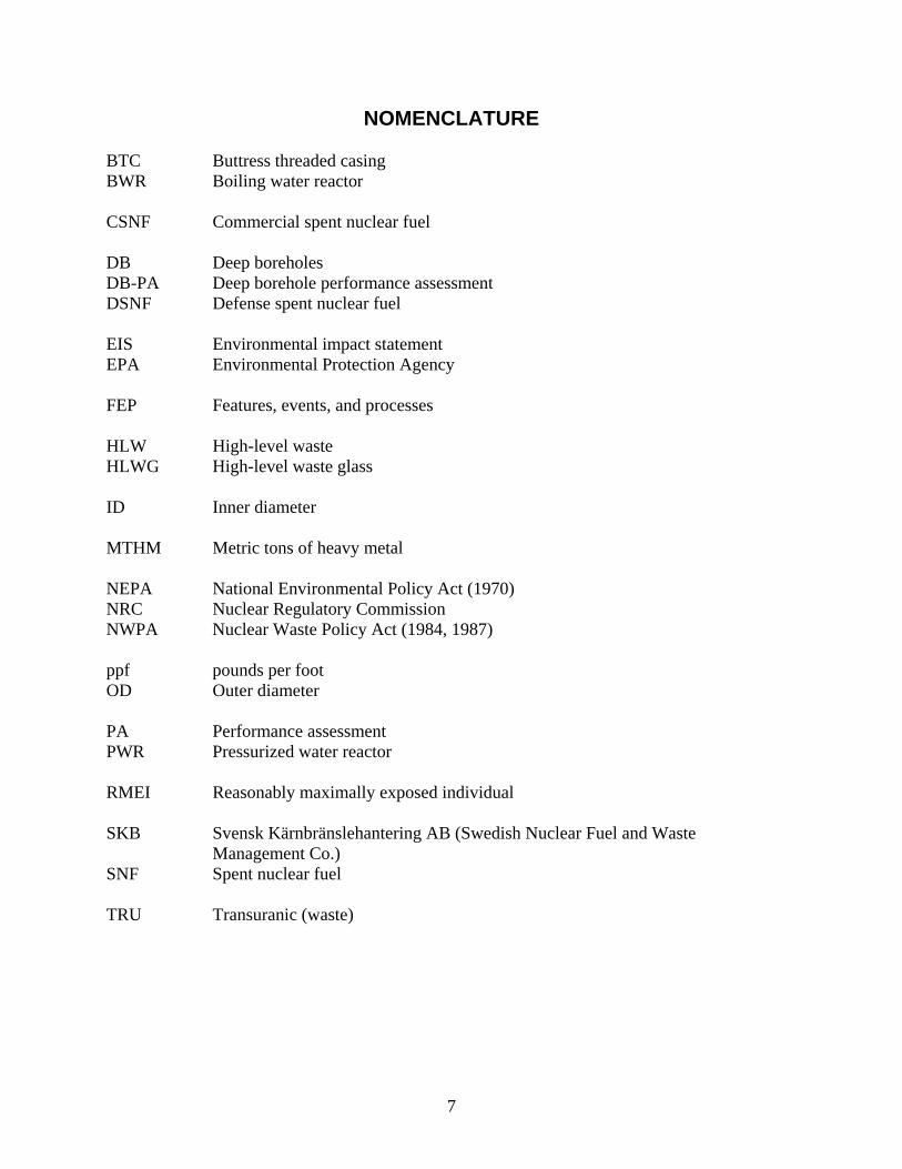
NOMENCLATURE BTC Buttress threaded casing BWR Boiling water reactor CSNF Commercial spent nuclear fuel DB Deep boreholes DB-PA Deep borehole performance assessment DSNF Defense spent nuclear fuel EIS Environmental impact statement EPA Environmental Protection Agency FEP Features, events, and processes HLW High-level waste HLWG High-level waste glass ID Inner diameter MTHM Metric tons of heavy metal NEPA National Environmental Policy Act (1970) NRC Nuclear Regulatory Commission NWPA Nuclear Waste Policy Act (1984, 1987) ppf pounds per foot OD Outer diameter PA Performance assessment PWR Pressurized water reactor RMEI Reasonably maximally exposed individual SKB Svensk Kärnbränslehantering AB (Swedish Nuclear Fuel and Waste Management Co.) SNF Spent nuclear fuel TRU Transuranic (waste)

8
9
1. INTRODUCTION
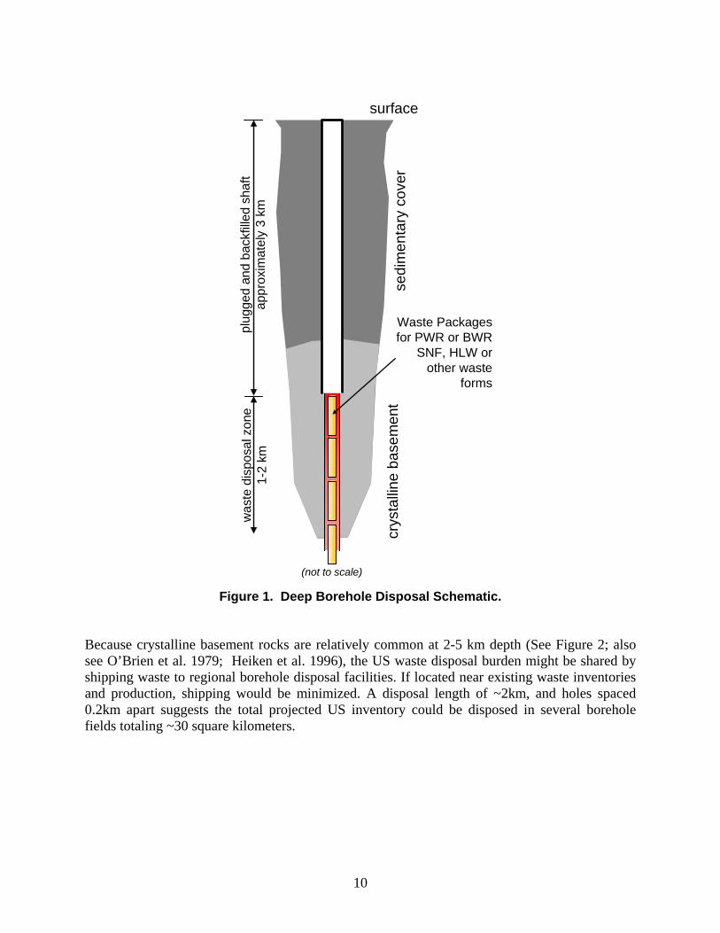
The purpose of this report is to document an evaluation and analysis of several factors (technical, regulatory, safety and performance) concerning the potential for a deep borehole disposal program, particularly with regard to the US, but also relevant to any agency or institution considering the potential for a borehole disposal program. In 1957 the US National Academy of Sciences Committee on Waste Disposal considered both deep borehole disposal of radioactive waste (in liquid form) and mined storage of radioactive waste in a positive light (National Academy of Sciences 1957). The intervening half-century has seen high-level waste (HLW) and spent nuclear fuel (SNF) disposal efforts in the US and other nations focus primarily on mined repositories, yet over the same time, the potential technical and cost advantages of deep borehole disposal have become more apparent. Radioactive waste emplaced in solid form (spent fuel or glass) at the bottom of deep (3-5 km) boreholes in crystalline basement rocks – typically granites (see schematic in Figure 1) - with off-the-shelf oilfield technology would be more effectively isolated from the biosphere than waste emplaced in shallower, mined repositories. The physical transport of radionuclides away from HLW and SNF at multi-kilometer depths would be limited by: low water content, low porosity and low permeability of crystalline basement rock, high overburden pressures that contribute to the sealing of transport pathways; and the presence of convectively stable saline fluids. Deep borehole disposal of radioactive waste has the added advantage of not producing as large a “thermal footprint” as a mined geologic repository, because boreholes placed more than ~200 m apart are unlikely to thermally affect one another. DOE estimates that 109,300 metric tons heavy metal (MTHM) of high-level waste and spent nuclear fuel – primarily commercial spent nuclear fuel (CSNF), but also DOE spent nuclear fuel (DSNF), and high-level waste glass (HLWG) – will need to be disposed of in the US (the projected US HLW and SNF inventory is summarized in Appendix A). Deep borehole disposal, characterization and excavation costs should scale linearly with waste inventory: small inventories require fewer boreholes; large inventories require more boreholes. Not needing a specially engineered waste package would also lower overall borehole disposal costs. Both aspects might make borehole disposal attractive for smaller national nuclear power efforts (having an inventory of 10,000 MTHM or less). In the US, the 70,000 MTHM of waste currently proposed for Yucca Mountain could be accommodated in about 600 deep boreholes (assuming each deep borehole had a 2 km long waste disposal zone that contained approximately 400 vertically stacked fuel assemblies). The remainder of the projected inventory of 109,300 MTHM could be fit into an additional 350 or so boreholes.
10
Figure 1. Deep Borehole Disposal Schematic. Because crystalline basement rocks are relatively common at 2-5 km depth (See Figure 2; also see O’Brien et al. 1979; Heiken et al. 1996), the US waste disposal burden might be shared by shipping waste to regional borehole disposal facilities. If located near existing waste inventories and production, shipping would be minimized. A disposal length of ~2km, and holes spaced 0.2km apart suggests the total projected US inventory could be disposed in several borehole fields totaling ~30 square kilometers.
Waste Packages for PWR or BWR
SNF, HLW or other waste
forms
(not to scale)
was
te d
ispo
sal z
one
1-2
km
crys
talli
ne b
asem
ent
sedi
men
tary
co
ver
plug
ged
and
back
fille
d sh
aft
appr
oxim
atel
y 3
km
surface
11
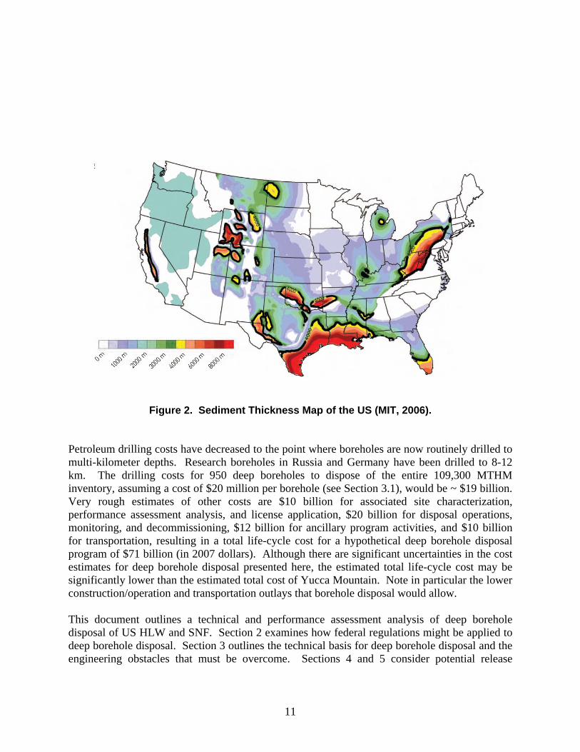
Figure 2. Sediment Thickness Map of the US (MIT, 2006). Petroleum drilling costs have decreased to the point where boreholes are now routinely drilled to multi-kilometer depths. Research boreholes in Russia and Germany have been drilled to 8-12 km. The drilling costs for 950 deep boreholes to dispose of the entire 109,300 MTHM inventory, assuming a cost of $20 million per borehole (see Section 3.1), would be ~ $19 billion. Very rough estimates of other costs are $10 billion for associated site characterization, performance assessment analysis, and license application, $20 billion for disposal operations, monitoring, and decommissioning, $12 billion for ancillary program activities, and $10 billion for transportation, resulting in a total life-cycle cost for a hypothetical deep borehole disposal program of $71 billion (in 2007 dollars). Although there are significant uncertainties in the cost estimates for deep borehole disposal presented here, the estimated total life-cycle cost may be significantly lower than the estimated total cost of Yucca Mountain. Note in particular the lower construction/operation and transportation outlays that borehole disposal would allow. This document outlines a technical and performance assessment analysis of deep borehole disposal of US HLW and SNF. Section 2 examines how federal regulations might be applied to deep borehole disposal. Section 3 outlines the technical basis for deep borehole disposal and the engineering obstacles that must be overcome. Sections 4 and 5 consider potential release

12
scenarios and present a preliminary performance assessment of the deep borehole disposal safety case. Section 6 concludes with a summary and recommendations of future work.
13
2. ASSUMPTIONS ABOUT A REGULATORY FRAMEWORK The current regulatory and legal framework for radioactive waste management is centered on mined geologic repositories, and was not intended to be applied to the long-term performance of deep borehole disposal systems. The Nuclear Waste Policy Act (NWPA) restricts consideration of geologic repositories in the United States to a single site, Yucca Mountain in Nevada, and EPA and NRC regulations (40 CFR part 197 and 10 CFR part 63, respectively) have been written specific for that site. Implementation of a deep borehole disposal system would, therefore, at a minimum, require amendment of the Nuclear Waste Policy Act. In principle, existing regulations from the 1980s that predate the selection of Yucca Mountain (i.e., 40 CFR part 191 and 10 CFR part 60) could be applied to borehole disposal systems without modification. However, these early regulations are inconsistent with recommendations provided to the EPA in 1995 by the National Research Council of the National Academies of Science and Engineering at the request of Congress, which called for system-level performance metrics based on annual risk, and may therefore be viewed as inadequate. In order to evaluate the system performance of a deep borehole disposal concept, it it necessary to adopt or develop a regulatory standard by which the performance can be measured. For the purposes of this preliminary analysis, the NWPA is assumed to be amended to allow consideration of sites other than Yucca Mountain and alternative disposal concepts, and new regulations are assumed to be promulgated that are similar in key regards to the current Yucca Mountain regulations, consistent with the EPA’s interpretation of the National Academies’ recommendations as promulgated in 40 CFR part 197. Thus, the primary overall performance measure of interest is mean annual dose to a hypothetical individual, with limits set at 0.15 mSv/yr for 10,000 years following disposal and for 1 mSv/yr for the period between 10,000 years and 1 million years. Other details of the regulatory framework, including screening criteria for potentially relevant features, events, and processes, as described in Section 4, are also assumed to be unchanged from those stated in 40 CFR part 197 and 10 CFR part 63, with the exception of human intrusion scenarios, for which new regulatory requirements would need to be developed. Four assumptions warrant further explanation. First, for simplicity in modeling, all characteristics of the hypothetically exposed individual are assumed to be identical to those of the “reasonably maximally exposed individual” defined in 40 CFR part 197: these characteristics are appropriate for humans living in arid regions similar to Yucca Mountain, but may need to be reconsidered for disposal sites in other regions. The assumption should in no way be interpreted as indicating a preference in this analysis for one geographic region over another: the assumption was made solely to allow the use of existing information regarding biosphere pathway analyses. As shown later in this report (see Section 5), this assumption has little or no impact on overall estimates of performance. Second, the exposed individual is assumed for the purposes of this analysis to live directly above the waste, rather than 18 kilometers away from the repository, as specified in 40 CFR part 197. This assumption focuses the analysis on the isolation provided by the deep geologic setting, and avoids speculation about site-specific aspects of geology closer to the land surface.
14
Third, requirements in both the NWPA and the EPA and NRC regulations specific to the retrievability of waste are assumed to be modified to reflect the more permanent disposal nature of a deep borehole disposal system. Although retrievability would be maintained during emplacement operations, waste may not be fully recoverable once the borehole has been sealed, and deep borehole systems may not be the best choice if permanent and irreversible disposal is not intended. Consistent with this observation, it should be noted that although the analysis presented in this report treats the direct disposal of SNF as a bounding performance case, deep borehole disposal systems may be particularly appropriate for other waste forms, including reprocessing wastes. Fourth, this analysis considers only a single disposal borehole. Actual disposal systems would likely contain an array of multiple boreholes, and it may be appropriate therefore to scale performance estimates upward for larger numbers of boreholes. Individual boreholes in a disposal array are assumed to be placed sufficiently far apart, however, that interactions among the holes will be insignificant and it would be conservative to assume that any single individual human could be exposed to the sum of the releases from all boreholes in a repository. A feature of deep borehole disposal concepts is the potential for multiple implementations where several disposal fields (borehole arrays) could be developed, each serving a given region, and each expected to encounter similar conditions at depth. The hydrogeologic and hydrochemical conditions common to deep granitic basement rock are thought to be advantageous to borehole disposal system performance. As shown in Figure 2, many regions within the US have granitic rocks at an appropriate depth and therefore many viable sites for borehole disposal are conceivable. In this regard, future regulatory frameworks developed for deep borehole disposal may best be served by establishing generic criteria (analogous to 10 CFR 60) rather than attempt to create multiple site-specific standards. Lastly, although the analysis presented here is for SNF as a bounding performance case, it should be recognized that borehole disposal systems may be particularly appropriate for other waste forms (e.g., spent sealed sources), and, thus, new regulations could reflect the generic factors which favor borehole disposal system performance, as well as acknowledge particular waste form characteristics (e.g., low heat production, low radionuclide concentration, etc).
15
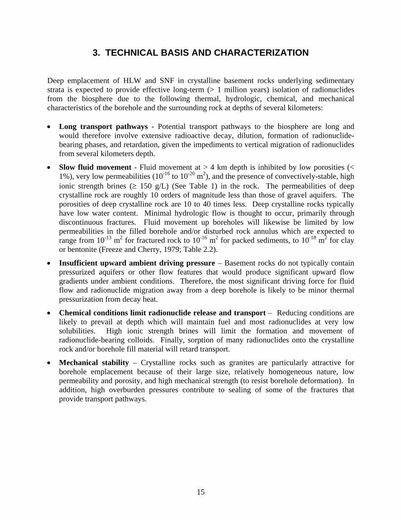
3. TECHNICAL BASIS AND CHARACTERIZATION Deep emplacement of HLW and SNF in crystalline basement rocks underlying sedimentary strata is expected to provide effective long-term (> 1 million years) isolation of radionuclides from the biosphere due to the following thermal, hydrologic, chemical, and mechanical characteristics of the borehole and the surrounding rock at depths of several kilometers: Long transport pathways - Potential transport pathways to the biosphere are long and
would therefore involve extensive radioactive decay, dilution, formation of radionuclide-bearing phases, and retardation, given the impediments to vertical migration of radionuclides from several kilometers depth.
Slow fluid movement - Fluid movement at > 4 km depth is inhibited by low porosities (< 1%), very low permeabilities (10-16 to 10-20 m2), and the presence of convectively-stable, high ionic strength brines ( 150 g/L) (See Table 1) in the rock. The permeabilities of deep crystalline rock are roughly 10 orders of magnitude less than those of gravel aquifers. The porosities of deep crystalline rock are 10 to 40 times less. Deep crystalline rocks typically have low water content. Minimal hydrologic flow is thought to occur, primarily through discontinuous fractures. Fluid movement up boreholes will likewise be limited by low permeabilities in the filled borehole and/or disturbed rock annulus which are expected to range from 10-13 m2 for fractured rock to 10-16 m2 for packed sediments, to 10-18 m2 for clay or bentonite (Freeze and Cherry, 1979; Table 2.2).
Insufficient upward ambient driving pressure – Basement rocks do not typically contain pressurized aquifers or other flow features that would produce significant upward flow gradients under ambient conditions. Therefore, the most significant driving force for fluid flow and radionuclide migration away from a deep borehole is likely to be minor thermal pressurization from decay heat.
Chemical conditions limit radionuclide release and transport – Reducing conditions are likely to prevail at depth which will maintain fuel and most radionuclides at very low solubilities. High ionic strength brines will limit the formation and movement of radionuclide-bearing colloids. Finally, sorption of many radionuclides onto the crystalline rock and/or borehole fill material will retard transport.
Mechanical stability – Crystalline rocks such as granites are particularly attractive for borehole emplacement because of their large size, relatively homogeneous nature, low permeability and porosity, and high mechanical strength (to resist borehole deformation). In addition, high overburden pressures contribute to sealing of some of the fractures that provide transport pathways.
16
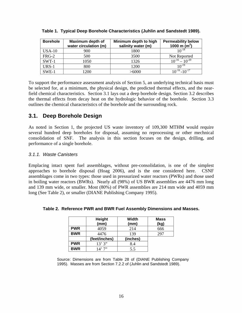
Table 1. Typical Deep Borehole Characteristics (Juhlin and Sandstedt 1989).
Borehole Maximum depth of water circulation (m)
Minimum depth to high salinity water (m)
Permeability below 1000 m (m2)
USA-10 900 1800 10-18 FRG-2 500 3500 Not Reported SWT-1 1050 1326 10-16 – 10-20 URS-1 800 1200 10-19 SWE-1 1200 >6000 10-16 -10-17
To support the performance assessment analysis of Section 5, an underlying technical basis must be selected for, at a minimum, the physical design, the predicted thermal effects, and the near-field chemical characteristics. Section 3.1 lays out a deep borehole design. Section 3.2 describes the thermal effects from decay heat on the hydrologic behavior of the borehole. Section 3.3 outlines the chemical characteristics of the borehole and the surrounding rock. 3.1. Deep Borehole Design As noted in Section 1, the projected US waste inventory of 109,300 MTHM would require several hundred deep boreholes for disposal, assuming no reprocessing or other mechnical consolidation of SNF. The analysis in this section focuses on the design, drilling, and performance of a single borehole. 3.1.1. Waste Canisters Emplacing intact spent fuel assemblages, without pre-consolidation, is one of the simplest approaches to borehole disposal (Hoag 2006), and is the one considered here. CSNF assemblages come in two types: those used in pressurized water reactors (PWRs) and those used in boiling water reactors (BWRs). Nearly all (98%) of US BWR assemblies are 4476 mm long and 139 mm wide, or smaller. Most (80%) of PWR assemblies are 214 mm wide and 4059 mm long (See Table 2), or smaller (DIANE Publishing Company 1995).
Table 2. Reference PWR and BWR Fuel Assembly Dimensions and Masses.
Height (mm)
Width (mm)
Mass (kg)
PWR 4059 214 666 BWR 4476 139 297 (feet/inches) (inches) PWR 13’ 3” 8.4 BWR 14’ 7” 5.5
Source: Dimensions are from Table 28 of (DIANE Publishing Company 1995). Masses are from Section 7.2.2 of (Juhlin and Sandstedt 1989).

17
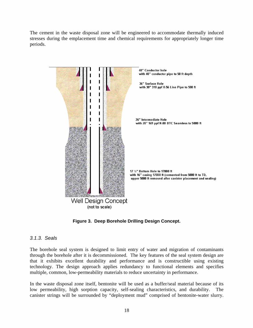
The transverse (i.e., diagonal width) dimension of a PWR assembly is 11.9” (302 mm); that of a BWR assembly is 7.8” (198 mm). A canister made of standard oilfield casing 5 m tall and having an inner diameter of 12-1/2” (318 mm) and an outside diameter of 13-3/8” (340 mm) could therefore hold one PWR assembly (Hoag 2006) or, with considerable extra space, one BWR assembly. End-caps would be welded on after assemblies had been inserted into the canisters. The disposal canister must be strong enough to prevent releases and exposure through the waste emplacement phase, including recovery operations for canisters that are stuck or damaged during emplacement. To maintain early physical stability, the inner void spaces would be filled with powdered bentonite. The canister is expected to possess no other intrinsically waste-isolating characteristics. 3.1.2. Boreholes It is anticipated that boreholes will be on the order of 5 km (~16,400 ft) deep. A 1-2 km long waste disposal zone (the lower portion of the borehole) might conceivably hold 200-400 canisters. The canisters could be emplaced one at a time or as part of a canister string – a grouping of 10 or 20 canisters. The in situ stress of the basement rock at depth will be assessed to determine deep borehole compatibility with the stress condition. The large boreholes will need to remain stable during the construction phase until the casing is cemented in, the waste canisters are emplaced, and the boreholes are plugged/backfilled. Also, horizontal stresses in the borehole region will increase after waste emplacement due to thermal expansion of the rock caused by heat from radioactive decay of the emplaced waste. These anticipated stresses will be evaluated as part of the borehole design. The design concept for deep borehole disposal is such that a borehole will accommodate a 13-3/8” (340 mm) OD canister. The depths for each borehole section are approximate and are presented as examples of the design which may vary depending on the specific site geology. However, the disposal concept is keyed to deep placement of waste at depths of 3-5 km (~10,000-16,400 ft). From the surface down the design is as follows (Figure 3):
1. 48” (1219 mm) Conductor hole with 40” (1016 mm) conductor pipe to 50 ft (~15 m) depth
2. 36” (914 mm) Surface Hole with 30” (762 mm) 310 ppf X-56 Line Pipe to 500 ft (~150 m)
3. 26” (660 mm) Intermediate Hole with 20” (508 mm) 169 ppf N-80 BTC Seamless to 5,000 ft (~1,500 m)
4. 17 ½” (445 mm) Bottom Hole with 16” (406 mm) casing to 17,000 ft (~5,200 m) (cemented from 5000 ft to total depth, upper 5000 ft removed after canister placement and sealing).
18
The cement in the waste disposal zone will be engineered to accommodate thermally induced stresses during the emplacement time and chemical requirements for appropriately longer time periods.
Figure 3. Deep Borehole Drilling Design Concept. 3.1.3. Seals The borehole seal system is designed to limit entry of water and migration of contaminants through the borehole after it is decommissioned. The key features of the seal system design are that it exhibits excellent durability and performance and is constructible using existing technology. The design approach applies redundancy to functional elements and specifies multiple, common, low-permeability materials to reduce uncertainty in performance. In the waste disposal zone itself, bentonite will be used as a buffer/seal material because of its low permeability, high sorption capacity, self-sealing characteristics, and durability. The canister strings will be surrounded by “deployment mud” comprised of bentonite-water slurry.
19
Canister strings will be separated by an approximately 1 m interval of compacted bentonite. Compacted bentonite will also be used at the top of the waste disposal zone, above the canister strings. Mechanical barriers (bridge plug, packer, etc.) in the casing at the top of the waste disposal zone could be used to isolate the wellbore. However, the elastomeric materials typically used as part of their sealing element will degrade over time and there may be operational difficulties in running (or retrieving) the plugs. Therefore this option is not considered to be desirable or highly feasible. The upper 1,500 m (5,000 ft) of the emplacement borehole casing will be removed after canister placement and sealing. A borehole seal system extending from the top of the waste disposal zone to the surface will be deployed to further isolate the emplaced wastes from the accessible environment. This borehole seal system will use a combination of bentonite, asphalt and concrete. The main seal will consist of compacted bentonite packs placed in a bentonite-water slurry (deployment mud). If the intermediate 20” casing is left in the borehole, this casing can be milled out at appropriate intervals to allow free movement of the sealing medium from the hole to the annulus and surrounding rock. A top seal will consist of asphalt from 500 m to 250 m, with a concrete plug extending from 250 m to the surface. Seal materials are discussed below. Compacted Clay Compacted clays are commonly proposed as primary sealing materials for nuclear waste repositories and have been extensively investigated against rigorous performance requirements (e.g., Van Geet 2007). Advantages of clays for sealing purposes include: low permeability, demonstrated longevity in many types of natural environments, deformability, sorptive capacity, and demonstrated successful utilization in practice for a variety of sealing purposes. Compacted clay as a borehole sealing component functions as a barrier to water flow and radionuclide movement and possibly to gas flow. The exact specification for compacted clays used in borehole sealing will depend upon site-specific details such as water chemistry, but an extensive experimental data base exists for the permeability of a variety of bentonite clays under a variety of conditions. Bentonite clay, a highly plastic swelling clay material (Mitchell 1993) is chosen here because of its positive sealing characteristics. Compacted bentonitic clay can generate swelling pressure and wetted swelling clay will seal fractures as it expands into available space and will ensure conformance between the clay seal component and the borehole walls. Bentonitic clays have been widely used in field and laboratory experiments concerned with radioactive waste disposal. Verification of engineering properties such as density, moisture content, permeability, or strength of compacted clay seals can be determined by direct and indirect measurement during construction. Asphalt
20
Asphalt is used to prevent water migration down the borehole. Asphalt is a strong cement, readily adhesive, highly waterproof, and durable. Furthermore, it is a plastic substance that is readily mixed with mineral aggregates. A range of viscosity is achievable for asphalt mixtures. It is highly resistant to most acids, salts, and alkalis. Asphalt has existed for tens of thousands of years as natural seeps. Longevity studies specific to DOE's Hanford site have utilized asphalt artifacts buried in ancient ceremonies to assess long-term stability (Wing and Gee 1994). Asphalt used as a seal component deep in the borehole will encounter a benign environment, devoid of ultraviolet light or an oxidizing atmosphere. For these reasons, it is believed that asphalt components will possess their design characteristics for an extended period of time. For example, studies conducted for WIPP indicate that the permeability of a massive asphalt column is expected to have an upper limit of 1×10-18 m2 for an extensive period of time (DOE 1996). Construction of the seal components containing asphalt can be accomplished using a slickline process where low-viscosity heated material is effectively pumped into the borehole. Sufficient construction practice and laboratory testing information is available to assure performance of the asphalt component. Laboratory validation tests to optimize viscosity may be desirable before final installation specifications are prepared. Concrete Concrete has low permeability and is widely used for hydraulic applications. The exact concrete composition will depend upon site-specific geology and water chemistry, but performance can be established through analogous industrial applications and in laboratory and field testing. For example, laboratory and field testing have shown that the Salado Mass Concrete used in the WIPP will remain structurally sound and possess very low permeability (between 2×10-21 and 1×10-17 m2) for long periods (DOE 1996). Standard ASTM specifications exist for both green and hydrated concrete properties. Quality control and a history of successful use in both civil construction and mining applications will assure proper placement and performance. 3.1.4. Cost and Schedule The deep disposal borehole design presented above is similar to the geothermal well design analyzed by Polsky et al. (2008) in well diameter, depth, and lithology. Therefore, the geothermal well construction cost and schedule analysis (combinations of labor, equipment, and materials) from Polsky et al. (2008) can be used to estimate costs and schedule for a deep disposal borehole. In 2008 dollars, a 5 km (~16,400 ft ) deep well will cost about $20 million and take about 110 days to construct (Figure 4). Thus base costs for ~1000 boreholes (to accommodate the total projected US inventory) would be ~$20B, not including emplacement operations, licensing, etc. Assuming emplacement and sealing could be accomplished in ~100 additional days, and with 10 separate disposal fields of ~100 holes each (covering ~3 square kilometers or 1-2 square miles), then ~50 years would be needed to emplace the total projected US inventory.

21
Figure 4. Deep Borehole Drilling Design Schedule and Cost. 3.2. Thermal Effects on Hydrologic Environment Thermal conditions in deep boreholes have been considered in detail recent years by Gibb and co-workers (e.g., Gibb, McTaggart et al. 2008). The most significant driving force for fluid flow and radionuclide migration away from a deep borehole is likely to be due to thermal pressurization from decay heat. An analysis of these effects on the hydrologic behavior of the deep borehole is presented here. 3.2.1. Heat Conduction Temperatures within the borehole and the host rock were simulated using a horizontal, two-dimensional model of thermal conduction implemented with the FEHM software code (Zyvoloski, Robinson et al. 1997). The model domain is 2,000 m square, centered on the
Wel
lbo
red
epth
(m
)
1000
2000
3000
4000
5000
1000
2000
3000
4000
5000
22
borehole, with an unstructured grid of progressively higher resolution near the waste canister. The thermal conduction model was constructed using the design basis concepts and dimensions from Hoag (2006), with a borehole diameter of about 50 cm and assuming a depth of 4 km. Constant temperature boundary conditions of 110 oC are assigned at the lateral boundaries of the model, which are sufficiently distant from the borehole to minimize impacts on the temperature simulations near the borehole. The geothermal gradient is assumed to be 25 oC/km and the average near surface temperature is assumed to be 10 oC. The model uses the heat output curves for a single average pressurized water reactor (PWR) fuel assembly that has been aged for 25 years, as used for the Yucca Mountain performance assessment modeling (Sandia National Laboratories 2008). Representative values of thermal conductivity for granite (3.0 W/ m oK), thermal conductivity of bentonite grout (0.8 W/ m oK), bulk density of granite (2750 kg/m3), specific heat of granite (790 J/kg oK), and porosity of granite (0.01) are used in the thermal conduction model. Figure 5 shows the temperature histories for the waste package wall, borehole wall, and several distances from the centerline of the borehole simulated in the vicinity of a borehole containing stacked individual spent fuel assemblies. The model did not attempt to simulate the temperatures within the waste canister. Temperature increases in the vicinity of the borehole are not large, do not persist for long periods of time, and drop off rapidly with distance from the borehole. Temperatures at the borehole wall peak at about 30 oC higher than the ambient temperature of the host rock within ten years of waste emplacement. Temperature increases would be significantly higher for fuel assemblies that have not been aged as long or if the thermal conductivity of the granite were significantly lower than the assumed value (3.0 W/ m oK). Simulated temperature increases near the waste emplacement borehole from the thermal conduction model are significantly lower than those calculated in a previous study by ONWI (Woodward-Clyde Consultants 1983), which showed simulated peak temperature increases at the borehole wall of 150 oC to 200 oC. However, the ONWI (Woodward-Clyde Consultants 1983) modeling considered reprocessed high-level waste (HLW) that had been aged only 10 years and which had a higher initial heat output of 2,600 W/canister compared to 580 W/canister of the older spent nuclear fuel considered here.

23
0.1 1 10 100 1000 10000Time (years)
100
110
120
130
140
150
Tem
pe
ratu
re (
o C
)
Waste Package WallBorehole Wall
1 m Distance
10 m Distance
100 m Distance
Figure 5. Temperature as a Function of Time and Distance from the Borehole for PWR Spent Fuel Assembly Disposal.
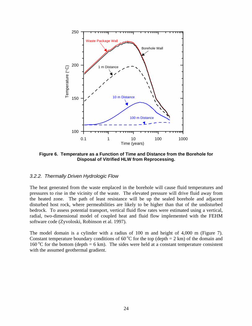
A similar analysis of thermal conduction was performed for borehole disposal of vitrified HLW from the reprocessing of spent nuclear fuel. This model uses the same model domain and parameter values as those described above. The heat output curves are for the current vitrified waste produced by reprocessing of commercial spent nuclear fuel in France (Andra 2005). For this analysis it is assumed that the waste is aged for 10 years before disposal and that the vitrified waste fills the waste canister with an inside diameter of 318 mm. The resulting temperature histories for varying distances from the centerline of the disposal borehole are shown in Figure 6. The simulated temperature increases are significantly higher for the disposal of HLW than those for disposal of spent fuel assemblies, with the temperature increasing by about 125 oC at the borehole wall at the time of peak temperature. Temperatures decline more rapidly for the disposal of HLW because the heat output from the reprocessing waste is dominated by the relatively short-lived fission products 90Sr and 137Cs. It should be noted that the thermal impacts of HLW disposal could easily be controlled by reducing the diameter of the waste canisters or by reducing the concentrations of fission products in the waste glass. Reducing the diameter of the waste canister by a factor of two would reduce the thermal output per meter of borehole and the peak increase in temperatures by about a factor of four.
24
0.1 1 10 100 1000Time (years)
100
150
200
250
Tem
pera
ture
(o C
)
Waste Package Wall
Borehole Wall
1 m Distance
10 m Distance
100 m Distance
Figure 6. Temperature as a Function of Time and Distance from the Borehole for Disposal of Vitrified HLW from Reprocessing.
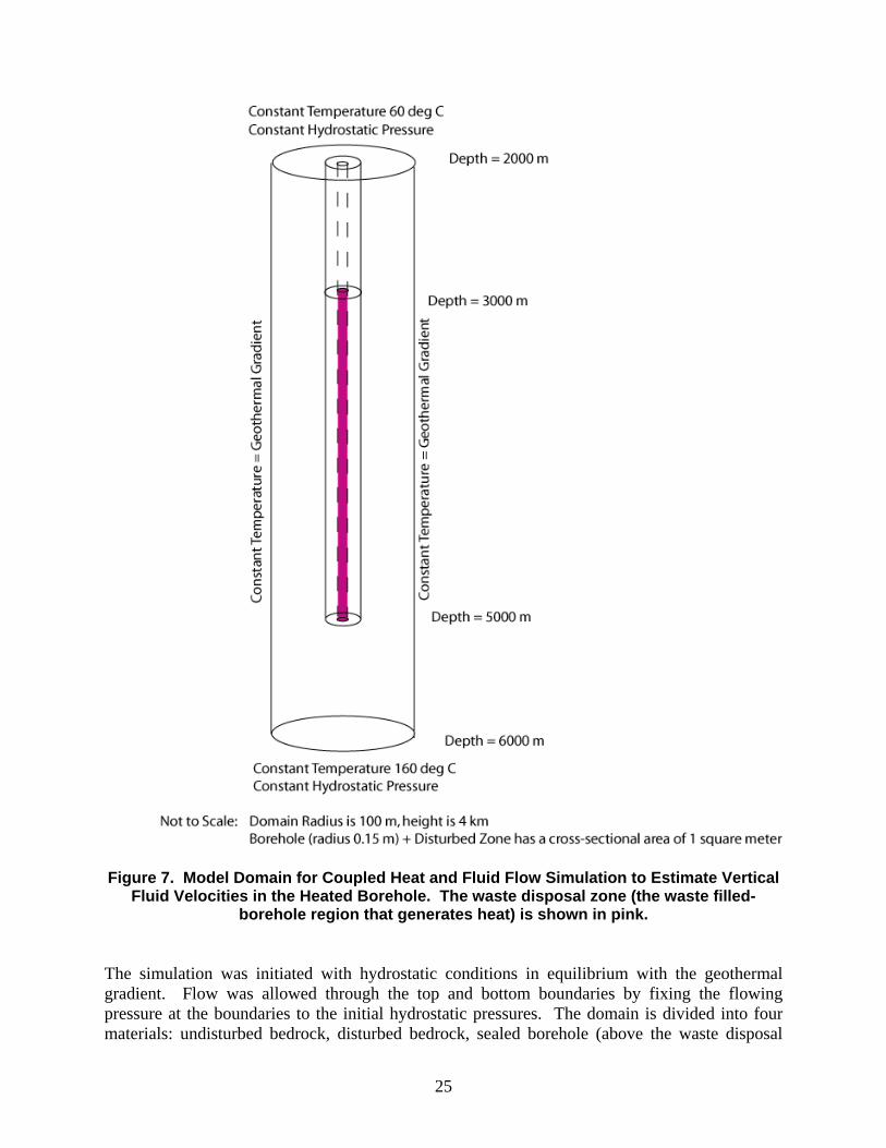
3.2.2. Thermally Driven Hydrologic Flow The heat generated from the waste emplaced in the borehole will cause fluid temperatures and pressures to rise in the vicinity of the waste. The elevated pressure will drive fluid away from the heated zone. The path of least resistance will be up the sealed borehole and adjacent disturbed host rock, where permeabilities are likely to be higher than that of the undisturbed bedrock. To assess potential transport, vertical fluid flow rates were estimated using a vertical, radial, two-dimensional model of coupled heat and fluid flow implemented with the FEHM software code (Zyvoloski, Robinson et al. 1997). The model domain is a cylinder with a radius of 100 m and height of 4,000 m (Figure 7). Constant temperature boundary conditions of 60 oC for the top (depth = 2 km) of the domain and 160 oC for the bottom (depth = 6 km). The sides were held at a constant temperature consistent with the assumed geothermal gradient.
25
Figure 7. Model Domain for Coupled Heat and Fluid Flow Simulation to Estimate Vertical
Fluid Velocities in the Heated Borehole. The waste disposal zone (the waste filled-borehole region that generates heat) is shown in pink.
The simulation was initiated with hydrostatic conditions in equilibrium with the geothermal gradient. Flow was allowed through the top and bottom boundaries by fixing the flowing pressure at the boundaries to the initial hydrostatic pressures. The domain is divided into four materials: undisturbed bedrock, disturbed bedrock, sealed borehole (above the waste disposal
26
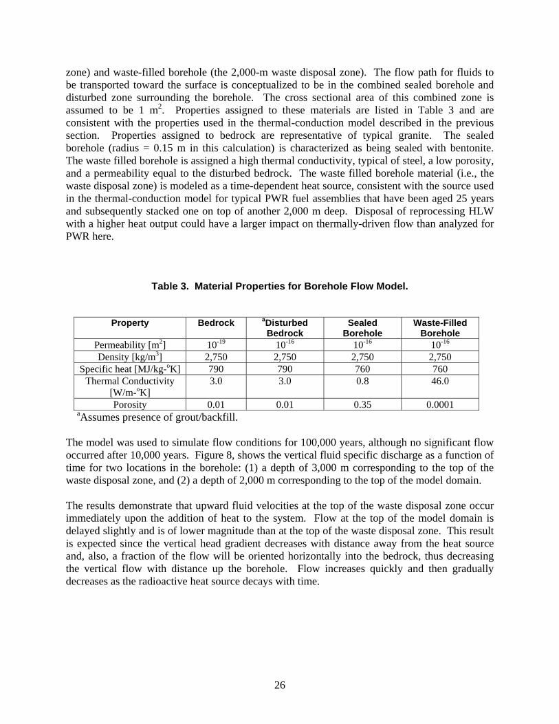
zone) and waste-filled borehole (the 2,000-m waste disposal zone). The flow path for fluids to be transported toward the surface is conceptualized to be in the combined sealed borehole and disturbed zone surrounding the borehole. The cross sectional area of this combined zone is assumed to be 1 m2. Properties assigned to these materials are listed in Table 3 and are consistent with the properties used in the thermal-conduction model described in the previous section. Properties assigned to bedrock are representative of typical granite. The sealed borehole (radius = 0.15 m in this calculation) is characterized as being sealed with bentonite. The waste filled borehole is assigned a high thermal conductivity, typical of steel, a low porosity, and a permeability equal to the disturbed bedrock. The waste filled borehole material (i.e., the waste disposal zone) is modeled as a time-dependent heat source, consistent with the source used in the thermal-conduction model for typical PWR fuel assemblies that have been aged 25 years and subsequently stacked one on top of another 2,000 m deep. Disposal of reprocessing HLW with a higher heat output could have a larger impact on thermally-driven flow than analyzed for PWR here.
Table 3. Material Properties for Borehole Flow Model.
Property Bedrock aDisturbed Bedrock
Sealed Borehole
Waste-Filled Borehole
Permeability [m2] 10-19 10-16 10-16 10-16 Density [kg/m3] 2,750 2,750 2,750 2,750
Specific heat [MJ/kg-oK] 790 790 760 760 Thermal Conductivity
[W/m-oK] 3.0 3.0 0.8 46.0
Porosity 0.01 0.01 0.35 0.0001 aAssumes presence of grout/backfill.
The model was used to simulate flow conditions for 100,000 years, although no significant flow occurred after 10,000 years. Figure 8, shows the vertical fluid specific discharge as a function of time for two locations in the borehole: (1) a depth of 3,000 m corresponding to the top of the waste disposal zone, and (2) a depth of 2,000 m corresponding to the top of the model domain. The results demonstrate that upward fluid velocities at the top of the waste disposal zone occur immediately upon the addition of heat to the system. Flow at the top of the model domain is delayed slightly and is of lower magnitude than at the top of the waste disposal zone. This result is expected since the vertical head gradient decreases with distance away from the heat source and, also, a fraction of the flow will be oriented horizontally into the bedrock, thus decreasing the vertical flow with distance up the borehole. Flow increases quickly and then gradually decreases as the radioactive heat source decays with time.

27
1 10 100 1 103
1 104
0
0.0075
0.015
0.0225
0.03
Top of Waste ZoneTop of Basement
Vertical Velocity Profile in Borehole
Time [yrs]
Ver
tica
l Spe
cifi
c D
isch
arge
[m
/yr]
0.0035
34 600
Figure 8. Vertical Specific Discharge at Two Locations as a Function of Time (Log Axis). Hydrologic pore velocity is equal to specific discharge divided by porosity. Pore velocity is equivalent to the transport velocity for an unretarded radionuclide. Since the flow path above the waste zone is comprised of an inner sealed borehole of radius 0.15 m and a porosity of 0.35 and
the outer ring-shaped disturbed zone of radius 1 = 0.564 m and a porosity of 0.01, the area weighted average porosity of the flow path is 0.034. Thus the maximum pore velocity at the top of the waste zone is 0.662 m/yr, but upward flow in this area only occurs for the first approximately 180 years. Maximum pore velocity at the top of the basement domain peaks at 0.103 m/yr at about 150 years. Upward flow will occur from approximately 34 to 600 years. The model results shown in Figure 8 indicate that upward fluid flow in the heated borehole only persists for a relatively short period of time (<1,000 yrs) after emplacement. Fluid movement is primarily caused by the local elevated pressures due to thermal expansion of the pore water. As the heat generation decreases, the temperature of the waste decreases and the fluid begins to contract, lowering pressure. Buoyancy forces are not significant in this system because heat flow is primarily conductive rather than advective. The permeability of the sealed borehole would have to be significantly higher and there would have to be a source of water connected to the borehole by a high-permeability conduit in order for buoyancy-driven flow (i.e., a chimney effect) to be an important factor. Because the actual pore water density will likely increase with depth due to salinity stratification, this simulation probably represents an upper bound on the fluid flow rates.
28
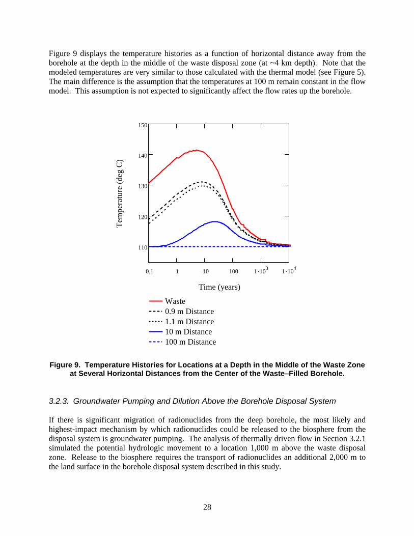
Figure 9 displays the temperature histories as a function of horizontal distance away from the borehole at the depth in the middle of the waste disposal zone (at ~4 km depth). Note that the modeled temperatures are very similar to those calculated with the thermal model (see Figure 5). The main difference is the assumption that the temperatures at 100 m remain constant in the flow model. This assumption is not expected to significantly affect the flow rates up the borehole.
0.1 1 10 100 1 103
1 104
110
120
130
140
150
Waste 0.9 m Distance1.1 m Distance10 m Distance100 m Distance
Time (years)
Tem
pera
ture
(de
g C
)
Figure 9. Temperature Histories for Locations at a Depth in the Middle of the Waste Zone
at Several Horizontal Distances from the Center of the Waste–Filled Borehole. 3.2.3. Groundwater Pumping and Dilution Above the Borehole Disposal System If there is significant migration of radionuclides from the deep borehole, the most likely and highest-impact mechanism by which radionuclides could be released to the biosphere from the disposal system is groundwater pumping. The analysis of thermally driven flow in Section 3.2.1 simulated the potential hydrologic movement to a location 1,000 m above the waste disposal zone. Release to the biosphere requires the transport of radionuclides an additional 2,000 m to the land surface in the borehole disposal system described in this study.

29
A simplified, but conservative, model of groundwater pumping and radionuclide transport is constructed to simulate the transport time between a release point 1,000 m above the waste and a hypothetical pumping well located near the disposal borehole. The model also simulates the amount of dilution associated with capturing radionuclide mass in the pumping well. The conceptual model is shown diagrammatically in Figure 10. The model domain is cylindrical with a radius of 10,000 m and a depth of 2,000 m. Specified-pressure boundary conditions corresponding to hydrostatic conditions are applied on the sides and bottom of the model domain, with a no-flow boundary condition at the upper surface. A continuous contaminant source with approximately 1 m2 area is specified on the bottom boundary directly beneath the pumping well. A specified volumetric flow rate of 0.0035 m3/year at the contaminant source corresponds to the maximum flow rate in the borehole simulated by the thermal-hydrologic model (Figure 8). The pumping well has a screened interval between 100 m and 200 m depth from which a specified volumetric flow rate is withdrawn.
Not to Scale: Model domain has a radius of 10 km and depth of 2 km. Contaminant source has a cross-sectional area of approximately 1 m2.
Figure 10. Model Domain for Groundwater Pumping and Radionuclide Transport.
The numerical model is implemented with the FEHM software code using a two-dimensional radial representation in which the grid resolution is finer near the axis of the well and the vertical grid spacing is 5 m. The horizontal permeability is 10-13 m2 and the vertical permeability is 10-14 m2 for a horizontal/vertical anisotropy ratio of 10. The permeability of the disposal borehole plus disturbed zone between the contaminant source and the pumping well is a factor of 10 higher than the surrounding rock. The porosity is assumed to be 0.01, which is appropriate for fractured bedrock, but is very low for most clastic sedimentary rocks. The aquifer compressibility is assigned a representative value of 10-4 MPa-1. Two pumping cases are simulated for differing capacity wells, one as a water supply for 25 people and one supplying water to 1000 people. Pumping rates are calculated using the average domestic water consumption in the U.S. of 86.5 gal/day/person (Van der Leeden et al. 1990).
pumping well
contaminant source
30
The groundwater pumping and radionuclide transport model is generic in nature and consequently is constructed with simplifying assumptions barring site-specific information. There are several aspects of this simplified groundwater pumping model that tend to underestimate the transport time between the contaminant source and the pumping well, and underestimate the amount of dilution of radionuclide concentrations:
No recharge is applied to the upper boundary of the model. In areas where there is substantial precipitation much of the groundwater captured by the pumping well would come from local recharge.
No ambient horizontal shallow groundwater flow is included in the model. The capture zone for a pumping well located in a regional horizontal groundwater flow field extends to a finite depth. The radionuclide source at 2,000 m depth would be below the capture zone of the pumping well for even moderate horizontal flow.
The permeability of the system does not decrease with depth in the model. Average permeability typically decreases by orders of magnitude over the depth range of 2,000 m in fractured bedrock, significantly reducing the fraction of deep fluids that would be captured in the pumping well.
The vertical anisotropy in permeability is a factor of 10 in the model. The vertical anisotropy in groundwater flow systems is often much greater than 10, particularly in sedimentary strata with shale aquitards. Higher values of vertical anisotropy significantly reduce the fraction of deep fluids that would be captured in the pumping well.
The value of porosity used in the model is representative of fractured bedrock. The value of porosity would be much higher for most porous sedimentary rocks. The low value of porosity used in the model would tend to underestimate the transport time between the contaminant source and the pumping well.
The volumetric inflow rate of contaminated fluid at the base of the model is held constant at the maximum rate simulated by the coupled heat and hydrologic flow model in Section 3.2.2. The contaminant inflow into the upper 2 km of the system would stop before 1,000 years based on the results shown in Figure 8.
Simulations are conducted only for a non-sorbing, non-decaying species. The transport time between the contaminant source and the pumping well would be much greater for sorbing radionuclides.
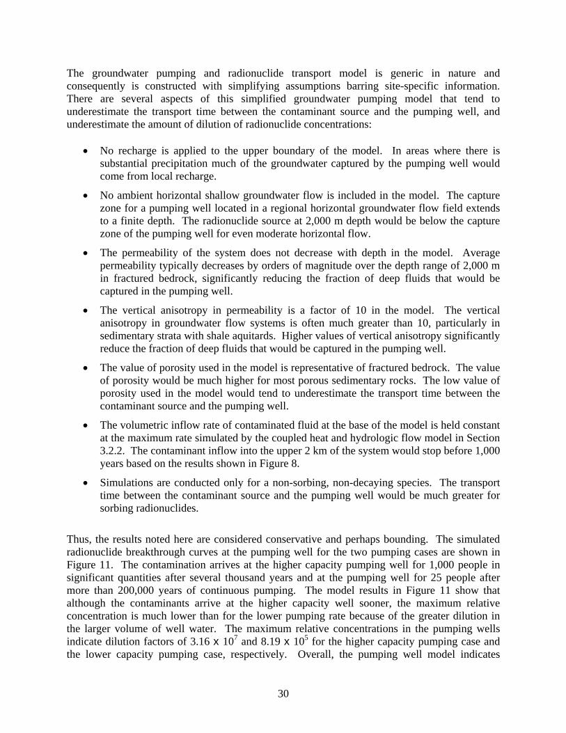
Thus, the results noted here are considered conservative and perhaps bounding. The simulated radionuclide breakthrough curves at the pumping well for the two pumping cases are shown in Figure 11. The contamination arrives at the higher capacity pumping well for 1,000 people in significant quantities after several thousand years and at the pumping well for 25 people after more than 200,000 years of continuous pumping. The model results in Figure 11 show that although the contaminants arrive at the higher capacity well sooner, the maximum relative concentration is much lower than for the lower pumping rate because of the greater dilution in the larger volume of well water. The maximum relative concentrations in the pumping wells indicate dilution factors of 3.16 x 10⁷ and 8.19 x 10⁵ for the higher capacity pumping case and the lower capacity pumping case, respectively. Overall, the pumping well model indicates
31
significant delays in the transport of radionuclides to the pumping well and large dilution factors relative to the radionuclide concentrations in the disposal borehole driven upward by thermal expansion of fluids near the disposal zone. In addition, the pumping well model significantly underestimates radionuclide transport times and the amount of dilution in radionuclide concentrations, as described above.
100 1000 10000 100000 1000000Time (years)
1E-010
1E-009
1E-008
1E-007
1E-006
1E-005
0.0001
Rel
ativ
e C
onc
entr
atio
n in
Pu
mp
ing
Wel
l Pumping Well (1000 people)
Pumping Well (25 people)
Figure 11. Simulated Breakthrough Curves for Two Groundwater Pumping Scenarios (Unit concentration at source).
In summary, even in the unlikely event of a water supply well located directly above the disposal borehole, significant delays in time and large amounts of dilution would occur during the capture of contaminants from the deep disposal system. Both of these factors would greatly reduce the potential radiological dose to hypothetical human receptors using that water supply. 3.3. Chemical Environment The geochemical behavior (solubility, sorption, colloidal behavior, etc.) of the projected waste inventory in the deep borehole environment sets limits on the stability of the uranium spent fuel matrix and on radionuclide transport to the biosphere. Radionuclide solubilities and sorption coefficients are therefore important input parameters for performance assessment calculations (Section 5). The US inventory of high-level radioactive waste and spent nuclear fuel used for the purposes of this analysis is 109,300 metric tons (DOE Office of Public Affairs, August 5, 2008) which includes the 70,000 MTHM considered for disposal at Yucca Mountain in addition to

32
waste to be generated in the future. The inventory and the important isotopes are discussed in greater detail in Appendix A. Fluids recovered from deep boreholes tend to be rich in sodium, calcium, and chloride. Lesser amounts of sulfate and carbonate are likely to be present. For the purposes of estimating radionuclide solubilities, a reasonable salinity is ~ 2-3 M/L, pHs are 8-9 and the system EH is ~ -300 mV (Anderson 2004). As discussed in Section 3.2, geothermal gradients are such that the temperatures at the bottom of the deep boreholes are expected to be above 100 oC. Oxygen tends to be scavenged, and the low redox state anchored, by the presence of reduced Fe and Mn in the basement rocks. Additional geochemically appealing features of deep boreholes are that the elevated temperatures of deep boreholes should stabilize the less soluble crystalline forms of radioelement oxide minerals, while high temperatures and high salinities will both favor the less soluble anhydrous forms of the oxide phases. Note though that the relatively high temperatures and salinities of deep fluids should accelerate the corrosion of steel pipes, fuel assemblies, and the waste itself. The scarcity of oxygen might slow the oxidation of spent fuel. 3.3.1. Radionuclide Solubilities Given the conditions outlined above, bounding estimates can be made of the dissolved levels of radionuclides likely to be present once basement fluids come into contact with spent fuel assemblages. Table 4 identifies likely solubility-limiting phases and provides estimates of dissolved radioelement concentrations at depth. Because of the uncertainty associated with estimating thermodynamic constants and the activity coefficients of aqueous species in high temperature, high ionic strength brines, the numbers in Table 4 are probably only accurate to within an order of magnitude. The relatively low solubility of UO2 under deep borehole conditions will favor stabilization of spent fuel rods. When contacted by water, fuel rods will have diminished thermodynamic drive to dissolve, thus slowing the matrix release of actinides and fission products. Yet even if fuel rods were to instantly dissolve to the thermodynamically stable actinide oxides, the solubilities of isotopes of Am, Ac, Cm, Np, Pa, Pu, Tc, and Th are lower than that of uranium – sometimes several orders of magnitude lower – suggesting that aqueous releases of these radionuclides will be small. Some species (e.g., 99Tc) have solubility limits that are below drinking water limits. It is less clear whether iodine, radium, and strontium will form solubility-limiting solids. If deep fluids contain appreciable sulfate, SrSO4 and RaSO4 might form to limit dissolved Sr and Ra levels. Dissolved carbonate might also lead to the formation of SrCO3. Radioiodine is a fission product that should become reduced to iodide given sufficient electron donors in the borehole domain. Unless iodide forms insoluble metal iodides, radioidide levels in solution adjacent to the fuel will probably be set by the available inventory. Pending closer examination of sulfate, carbonate, and heavy metal contents of borehole fluids, no limiting concentrations are set for I, Sr, and Ra.
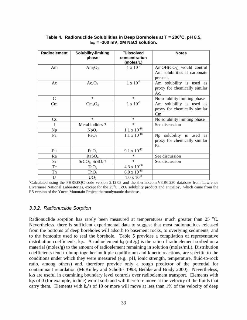
33
Table 4. Radionuclide Solubilities in Deep Boreholes at T = 200oC, pH 8.5,
EH = -300 mV, 2M NaCl solution.
Radioelement Solubility-limiting phase
aDissolved concentration
(moles/L)
Notes
Am Am2O3 1 x 10⁻⁹ AmOH(CO3) would control Am solubilities if carbonate present.
Ac Ac2O3 1 x 10⁻⁹ Am solubility is used as proxy for chemically similar Ac.
C * * No solubility limiting phase Cm Cm2O3 1 x 10⁻⁹ Am solubility is used as
proxy for chemically similar Cm.
Cs * * No solubility limiting phase I Metal iodides ? * See discussion
Np NpO2 1.1 x 10⁻¹⁸ Pa PaO2 1.1 x 10⁻¹⁸ Np solubility is used as
proxy for chemically similar Pa.
Pu PuO2 9.1 x 10⁻¹² Ra RaSO4 * See discussion Sr SrCO3, SrSO4 ? * See discussion Tc TcO2 4.3 x 10-38 Th ThO2 6.0 x 10⁻¹⁵ U UO2 1.0 x 10⁻⁸
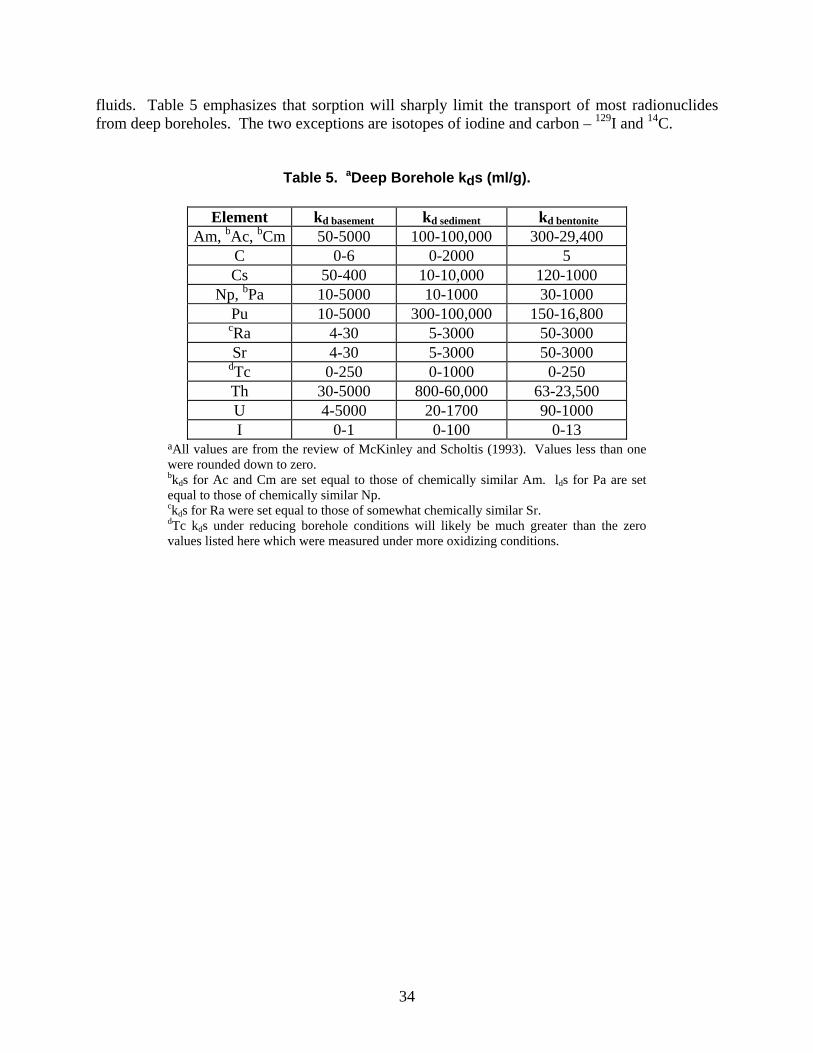
aCalculated using the PHREEQC code version 2.12.03 and the thermo.com.V8.R6.230 database from Lawrence Livermore National Laboratories, except for the 25oC TcO2 solubility product and enthalpy, which came from the R5 version of the Yucca Mountain Project thermodynamic database. 3.3.2. Radionuclide Sorption Radionuclide sorption has rarely been measured at temperatures much greater than 25 oC. Nevertheless, there is sufficient experimental data to suggest that most radionuclides released from the bottoms of deep boreholes will adsorb to basement rocks, to overlying sediments, and to the bentonite used to seal the borehole. Table 5 provides a compilation of representative distribution coefficients, kds. A radioelement kd (mL/g) is the ratio of radioelement sorbed on a material (moles/g) to the amount of radioelement remaining in solution (moles/mL). Distribution coefficients tend to lump together multiple equilibrium and kinetic reactions, are specific to the conditions under which they were measured (e.g., pH, ionic strength, temperature, fluid-to-rock ratio, among others) and, therefore provide only a rough predictor of the potential for contaminant retardation (McKinley and Scholtis 1993; Bethke and Brady 2000). Nevertheless, kds are useful in examining boundary level controls over radioelement transport. Elements with kds of 0 (for example, iodine) won’t sorb and will therefore move at the velocity of the fluids that carry them. Elements with kd’s of 10 or more will move at less than 1% of the velocity of deep
34
fluids. Table 5 emphasizes that sorption will sharply limit the transport of most radionuclides from deep boreholes. The two exceptions are isotopes of iodine and carbon – 129I and 14C.
Table 5. aDeep Borehole kds (ml/g).
aAll values are from the review of McKinley and Scholtis (1993). Values less than one were rounded down to zero. bkds for Ac and Cm are set equal to those of chemically similar Am. lds for Pa are set equal to those of chemically similar Np. ckds for Ra were set equal to those of somewhat chemically similar Sr. dTc kds under reducing borehole conditions will likely be much greater than the zero values listed here which were measured under more oxidizing conditions.
Element kd basement kd sediment kd bentonite Am, bAc, bCm 50-5000 100-100,000 300-29,400
C 0-6 0-2000 5 Cs 50-400 10-10,000 120-1000
Np, bPa 10-5000 10-1000 30-1000 Pu 10-5000 300-100,000 150-16,800
cRa 4-30 5-3000 50-3000 Sr 4-30 5-3000 50-3000
dTc 0-250 0-1000 0-250 Th 30-5000 800-60,000 63-23,500 U 4-5000 20-1700 90-1000 I 0-1 0-100 0-13
35
4. SCENARIO ANALYSIS The selection of scenarios for analysis in the deep borehole disposal performance assessment is based on the assumption that regulatory requirements for deep borehole disposal will be essentially the same as those currently extant in 10 CFR 63. Specifically, the performance measure of interest is assumed to be the mean annual dose to a hypothetical member of the public (the “reasonably maximally exposed individual” of 40 CFR 197.21) who lives in the accessible environment near the disposal site. Consistent with approach taken in 40 CFR 197, it is assumed that the mean annual dose shall include probability-weighted consequences of releases due to all significant features, events, and processes (FEPs), and shall account for uncertainty associated with those FEPs. As described in Section 4.1, a FEP screening approach similar to that taken for both Yucca Mountain and WIPP is adopted to identify the significant FEPs that should be included in the quantitative performance assessment. Section 4.2 describes how those FEPs that are identified as being significant to performance are combined into the scenarios analyzed in Section 5. 4.1. Identification of Relevant Features, Events, and Processes Various programs in the US and other nations have compiled exhaustive lists of FEPs for mined geologic disposal that should be evaluated for potential relevance to deep borehole disposal of radioactive wastes. Depending on subjective decisions about how to partition the essentially infinite number of possible future occurrences, these lists can range from a relatively small number of broadly defined FEPs to a very large number of more narrowly defined FEPs. In practice, lists that aggregate phenomena at relatively coarse levels have proven to be suitable for evaluation in regulatory settings in the US (e.g., WIPP Compliance Certification Application [DOE 1996, DOE 2004], Yucca Mountain License Application [DOE 2008b, Sandia National Laboratories 2008b]). Once potentially relevant FEPs for deep borehole disposal have been identified, they must be evaluated against screening criteria provided in US regulations. Specifically, EPA regulations for Yucca Mountain state that FEPs that have an annual probability of occurrence less than one chance in 100,000,000 in the first 10,000 years after closure may be excluded from the analysis. Features, events, and processes that have higher probabilities, but do not significantly change the results of long-term performance assessments, may also be omitted from the analysis (40 CFR 197.36(a)(1)). In addition, some potentially relevant FEPs are screened from further consideration because they are inconsistent with specific aspects of the regulatory requirements. For example, existing regulations for WIPP and Yucca Mountain indicate that performance assessments should not include consequences of deliberate human acts of sabotage or disruption in the far future. For this analysis it is assumed that all regulatory requirements relevant to FEP analyses for Yucca Mountain apply equally to deep borehole disposal. The FEP list from the Yucca Mountain license application (see Appendix B, Table B-1) was adopted as a reasonable starting point for evaluation. Each of the 374 FEPs on this list has been considered (screened) for potential relevance to deep borehole disposal; FEPs that may be unique to deep borehole disposal have been considered and compared to the list to identify existing
36
FEPs that capture the processes of interest and concern for boreholes. No new FEPs were identified in this process, confirming that, although the Yucca Mountain list was specifically tailored for a mined repository, it remains a useful starting point for this preliminary analysis. In evaluating Yucca Mountain FEPs for the deep borehole disposal performance assessment, the following assumptions are made that go beyond the basic assumption that regulatory criteria are the same as those stated in 40 CFR part 197.
Biosphere exposure is assumed to occur via a contaminated groundwater well immediately adjacent to the borehole. There is therefore no release pathway of interest in the unsaturated zone (UZ). All relevant biosphere pathways associated with contaminated well water (e.g., irrigation, crops, livestock, drinking, etc.) are included.
No credit is taken for the waste package or waste form as flow barriers. Therefore, all FEPs related to the performance of waste package and waste form as flow and transport barriers are excluded from the analysis.
Chemical effects of the waste package and waste form are of interest and must be evaluated further.
The “Drift” is the portion of the borehole that contains waste (i.e., the waste disposal zone).
The engineered barrier system (EBS) includes seals and drifts, but the effective contribution comes from the borehole seals.
Backfill, to the extent that it is used, is the material that is emplaced in the waste disposal zone of the borehole surrounding waste canisters.
There are two release pathways of primary interest: transport through the EBS (seals), and transport through the saturated zone (SZ) in the surrounding rock
Naval and DOE spent fuels (called out specifically in the YM analysis) are omitted from this analysis.
Retrievability of waste, which is required to be feasible under current regulations, is assumed to be excluded as a position of policy.
Tables B-1 and B-2 in Appendix B summarize the screening decisions for each FEP (whether a FEP is likely to need to be included in or excluded from a full performance assessment for deep borehole disposal) and also includes a qualitative estimate of the level of effort likely to be required to provide a robust basis for the screening of the FEP. For excluded FEPs, 1 means the technical or regulatory basis is readily available and all that is needed is documentation; 2 means new technical work likely is needed, and 3 indicates a potentially significant amount of work is needed. For included FEPs, 1 indicates that this is a normal part of modeling, 2 indicates that this is a significant aspect of the modeling, and 3 indicates possible modeling challenges. Notes entered in this column provide clarification about how the FEP may need to be considered for deep borehole disposal.

37
Section 4.3 provides additional support for the decision to exclude criticality, molecular diffusion, and thermal hydrofracturing from the performance assessment. 4.2. Scenario Selection Consideration of the FEPs that have a preliminary screening of “included” in Table 9 shows that radionuclides emplaced in deep boreholes might reach the biosphere along one, or a combination, of three principal paths: 1) up the borehole (includes accidental release during emplacement); 2) along the annulus of disturbed rock; and/or 3) radially out through groundwater. These pathways are described below as three scenarios chosen for analysis in a preliminary performance assessment. A more complete screening of the FEPs may identify additional scenarios of interest, and may also show that some aspects of the chosen scenarios do not need further analysis. Scenario 1: Transport in the borehole. Hydrologic flow up the borehole transports radionuclides to a shallow aquifer from which they are pumped to the biosphere – This scenario requires sufficiently high permeability within the borehole and a sustained upward gradient in hydrologic potential for it to occur. Vertical permeability within the borehole in the waste disposal zone may be relatively high, given the presumably rapid degradation of the disposal canisters stacked within the borehole. Vertical permeability within the borehole above the level of waste emplacement will be engineered to be very low and would require failure of the borehole grout and seals (or bypassing of such seals) to permit significant fluid flow up the borehole. An upward gradient in hydrologic potential within the borehole could result from: a) ambient hydrologic conditions, b) thermal pressurization of fluid within the waste disposal zone from waste heat, c) buoyancy of heated fluid within the waste disposal zone, or d) thermo-chemical reactions that release water and/or gases within the waste disposal zone. Scenario 2: Transport in disturbed rock around the borehole. Hydrologic flow up the annulus of disturbed rock surrounding the borehole transports radionuclides to a shallow aquifer from which they are pumped to the biosphere – This scenario requires sufficiently high permeability in the rock surrounding the borehole and a sustained upward gradient in hydrologic potential for it to occur. Vertical permeability within disturbed rock in the waste disposal zone and in the overlying rock may be relatively high if the annular space is not effectively grouted during borehole construction and/or abandonment. Vertical permeability in the crystalline rock immediately outside the heated volume near the waste disposal zone could be increased because thermo-mechanical effects would reduce the vertical mechanical stress. An upward gradient in hydrologic potential within the annulus of the borehole could result from: a) ambient hydrologic conditions, b) thermal pressurization of fluids within the waste disposal zone from waste heat, c) buoyancy of heated fluids within the waste disposal zone, or d) thermo-chemical reactions that release water and/or gases within the waste disposal zone. Scenario 3: Transport in surrounding rock away from the borehole. Hydrologic flow up through the crystalline basement and sedimentary cover transports radionuclides to a shallow aquifer from which they are pumped to the biosphere – This scenario requires sufficiently high permeability within fracture zones and/or faults in the crystalline basement and sedimentary cover and a sustained upward gradient in hydrologic potential for it to occur. Given the low
38
vertical permeability of the crystalline basement rocks and the stratified sedimentary cover, a through-going feature such as an interconnected group of fracture zones or faults would be required to conduct significant quantities of fluid to a shallow aquifer. 4.3. Justification for Exclusion of Selected Features, Events, and Processes 4.3.1. Exclusion of Criticality from Deep Borehole Disposal The possibility of a self-sustained nuclear chain reaction event (critical event or “criticality”) has always been a consideration of geologic disposal, similar to any facility that handles fissile material. As early as 1974, the criticality scenario class was identified as a potential event in the Waste Isolation Pilot Plant (WIPP) in southern New Mexico, a repository for transuranic (TRU) waste which opened in 1999 (Rechard, Sanchez et al. 2001). Because of the potential interest, a preliminary discussion is provided concerning the credibility of a down-hole criticality with respect to inclusion or exclusion from a formal, site-specific performance assessment for SNF. HLW and other radioactive waste such as small spent sealed sources would present a much lower potential for criticality. During transportation to the site and during repository operations when humans are present, stringent administrative and physical measures would be in place to prevent criticality. These standard operational aspects are not discussed here. Rather, this discussion focuses on the low probability of criticality after deep borehole disposal in two general locations: in the waste canister (Section 4.3.1.1); and outside the waste canister in the near or far field (Section 4.3.1.1). The focus here is on direct disposal of spent fuel assemblies rather than HLW which has most of the fissile mass removed. 4.3.1.1. Low Probability of Criticality in a Single Waste Canister As noted in Section 4.1, a FEP can be excluded if (a) the annual probability of occurrence is less than one chance in 10-8 (i.e., low probability), or (b) its omission does not significantly change the results of long-term performance assessments (i.e., low consequence). New regulations applicable to deep borehole disposal (see Section 2) would likely retain this concept. Fissile material cannot become critical after disposal unless several conditions are met. Specifically, several features must be present, and events and especially geologic processes must act to alter the waste canister and its contents for a critical event to occur inside the canister. However, physical constraints limit the possibility of criticality inside the waste canister. To elaborate, because of the small diameter of a deep borehole, the number of CSNF assemblies that can be placed in a canister is limited. This criticality analysis assumes one PWR assembly is placed in a canister. One PWR assembly cannot become critical even when fully flooded. For low enriched uranium, the heterogeneous lumping of the uranium in an assembly is the most reactive configuration. Hence, any re-arrangement to a more homogeneous configuration lowers the reactivity. Based on 383 kg of uranium in a reference PWR (derived from Table 7), the amount of fissile 235U would vary between 3% (11.5 kg) for older fuel, 5% (19 kg) for fuel
39
currently in use, and perhaps a maximum of 10% (38 kg) for fuel sometime in the future. Yet, homogeneous mixtures of rock with high silica content (~75%wt silica), typically require >350 kg, >65 kg, or >30 kg of fissile 235U, respectively, ignoring the presence of any neutron absorbing elements such fission products, actinides, or purposely placed boron or gadolinium (Figure 9 from Rechard, Sanchez et al. 2003). Hence, only a homogeneous mixture of future fresh fuel at 10% enrichment could be critical in a single canister. In reality fission products and actinides would also be present in spent fuel, which would lower reactivity, hence, even future CSNF at an initial 10% enrichment would not be critical. More importantly, the diameter of the canister or borehole is not sufficient to prevent excess loss of neutrons within the fissile material as discussed in Section 4.3.1.2 for criticality outside the waste canister. For DOE SNF, the packaging scheme could limit the fissile 235U roughly to those amounts listed above (i.e., <350 kg for DOE SNF with <3% enrichment, <65 kg for DOE SNF with <5% enrichment, and <30 kg for DOE SNF with any other enrichment. 4.3.1.2. Low Probability of Criticality Outside the Waste Canisters Because of the physical constraint on the amount of fissile mass in a canister, criticality is not credible inside the canister. Criticality directly outside the canister also has physical constraints. Specifically, the minimum diameter of a homogeneous critical sphere is greater than the 0.445 m (17.5 in.) diameter borehole at depth (Figure 3). For example, the minimum diameter for a critical sphere at 10% enrichment and a 20 kg/m3 concentration at the minimum mass of 30 kg is 0.71 m; More realistic depositional concentrations of 5 kg/m3 (concentrations found in high grade ores ~2300 ppm) result in a minimum diameter of 1.1 m. Ideal planar configurations must also be at least 0.5 m thick, as corroborated by the natural reactors at Oklo that were about 1 m thick (Rechard et al. 2001; Section 3.5). Hence, criticality is not credible in the confines of the borehole at depths where disposal occurs. If a critical event is to occur outside the package, geologic processes must transport fissile material from several packages into the host rock or to depositional zones away from the disposal area and then assemble the fissile material into a critical configuration. These geologic processes are the same as must be invoked to remove fission products and actinides from the waste and transport them to the biosphere. As discussed in Section 3.3, the chemical environment in a deep borehole greatly limits the mobility of radionuclides, in general, and fissile material, in particular. There is no likely mechanism to oxidize the uranium to the more mobile species (i.e., U+6); hence, the solubility of uranium (U+4) in the anoxic environment of the borehole is 10-8 mole/L (2.38 10-6 kg/m3) (Table 4). As noted above, the concentration, either as a liquid or solid, must reach ~5 kg/m3 (~2300 ppm) to go critical (6 orders of magnitude higher concentration). More importantly, enough mass must be released from the borehole waste disposal zone. As noted below in Section 5, uranium is not transported out of the waste disposal zone. At the upward velocities from thermal effects that might occur in the initial 200 years after disposal, it would take 9 billion years to deplete the uranium in a single waste canister (383 kg). In one million years, about 0.04 kg would be depleted using the thermal upward velocity in the initial 200 years. If a disposal borehole had 450 canisters, the maximum release from the disposal zone would only be
40
about 19 kg, of which at most 10% would be fissile. A release of 1.9 kg of fissile 235U is much less than the 30 kg necessary to become critical. Hence, criticality in the far field is not credible. 4.3.2. Exclusion of Molecular Diffusion from Deep Borehole Disposal Chemical diffusion of radionuclides through the host rock matrix and borehole seals will result in the migration of contaminant mass, even in the absence of fluid flow. The potential impact of diffusion on radionuclide containment is evaluated here using an analytical solution for one-dimensional diffusive transport through a porous medium, assuming a constant radionuclide concentration in the waste disposal zone. The solution is for a non-sorbing species without radioactive decay, according to the following equation (Crank 1956):
tD
zerfc
C
C
eff20 (Eq. 4-1)
where C is the radionuclide concentration, C0 is the radionuclide concentration in the waste zone, erfc is the complementary error function, z is the distance above the waste, Deff is the effective diffusion coefficient, and t is time. The vertical concentration profile above the waste from this solution is plotted in Figure 12 at 1,000,000 years after waste emplacement, assuming an effective diffusion coefficient of 1 x 10⁻¹⁰ m2/s. Migration of radionuclide mass via diffusion has occurred to a vertical distance of about 200 m above the waste in this time. The concentrations shown in Figure 12 are overestimated with regard to the geometry of the system. Diffusion from the top of the waste disposal zone would have a radial component as well as a vertical component, reducing the migration rate in the vertical direction. Radionuclides that sorb on the rock matrix and borehole sealing material would be significantly retarded during diffusive migration. In addition, radioactive decay for radionuclides with half lives less than the time frame of the calculation would decrease concentrations. The value of the effective diffusion coefficient (1 x 10⁻¹⁰ m2/s) used in the analysis is relatively high for granite, but is approximately representative of the elevated temperature conditions in the deep borehole disposal system. Overall, diffusion in crystalline host rock and borehole seals is a slow process for the migration of radionuclide contamination, even on geologic time scales. Given the depth of deep borehole disposal system, diffusion can be excluded as a significant process from further consideration in performance assessment analyses.
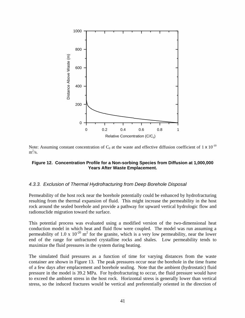
41
0 0.2 0.4 0.6 0.8 1
Relative Concentration (C/C0)
0
200
400
600
800
1000
Dis
tan
ce A
bove
Was
te (
m)
Note: Assuming constant concentration of C0 at the waste and effective diffusion coefficient of 1 x 10⁻¹⁰ m2/s.
Figure 12. Concentration Profile for a Non-sorbing Species from Diffusion at 1,000,000 Years After Waste Emplacement.
4.3.3. Exclusion of Thermal Hydrofracturing from Deep Borehole Disposal Permeability of the host rock near the borehole potentially could be enhanced by hydrofracturing resulting from the thermal expansion of fluid. This might increase the permeability in the host rock around the sealed borehole and provide a pathway for upward vertical hydrologic flow and radionuclide migration toward the surface. This potential process was evaluated using a modified version of the two-dimensional heat conduction model in which heat and fluid flow were coupled. The model was run assuming a permeability of 1.0 x 10⁻²⁰ m2 for the granite, which is a very low permeability, near the lower end of the range for unfractured crystalline rocks and shales. Low permeability tends to maximize the fluid pressures in the system during heating. The simulated fluid pressures as a function of time for varying distances from the waste container are shown in Figure 13. The peak pressures occur near the borehole in the time frame of a few days after emplacement and borehole sealing. Note that the ambient (hydrostatic) fluid pressure in the model is 39.2 MPa. For hydrofracturing to occur, the fluid pressure would have to exceed the ambient stress in the host rock. Horizontal stress is generally lower than vertical stress, so the induced fractures would be vertical and preferentially oriented in the direction of
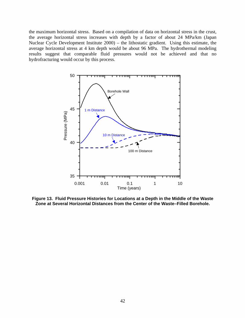
42
the maximum horizontal stress. Based on a compilation of data on horizontal stress in the crust, the average horizontal stress increases with depth by a factor of about 24 MPa/km (Japan Nuclear Cycle Development Institute 2000) – the lithostatic gradient. Using this estimate, the average horizontal stress at 4 km depth would be about 96 MPa. The hydrothermal modeling results suggest that comparable fluid pressures would not be achieved and that no hydrofracturing would occur by this process.
0.001 0.01 0.1 1 10Time (years)
35
40
45
50
Pre
ssur
e (
MP
a)
Borehole Wall
1 m Distance
10 m Distance
100 m Distance
Figure 13. Fluid Pressure Histories for Locations at a Depth in the Middle of the Waste Zone at Several Horizontal Distances from the Center of the Waste–Filled Borehole.

43
5. PERFORMANCE ASSESSMENT Based on the scenario analysis described in Section 4, a preliminary deep borehole performance assessment (DB-PA) was performed for a simplified and conservative representation of combined radionuclide releases from Scenarios 1 and 2 from Section 4.2. The conceptual model is as follows:
400 PWR assemblies (~150 MTHM) vertically stacked down the length of the waste disposal zone (~ 2 km).
Initial radionuclide inventory consistent with Appendix A (CSNF/PWR aged to year 2117). Effects of ingrowth accounted for in a bounding fashion.
Dissolved concentrations in the waste disposal zone limited by thermal-chemical conditions (see Table 4).
Thermally driven hydrologic flow from the top of the waste disposal zone upward through 1000 m of a bentonite sealed borehole with a specific discharge of 0.017 m/yr for 200 years (see Figure 8).
Radionuclide transport up the borehole calculated using a 1-dimensional analytical solution to the advection-dispersion equation (see Equation 5-1 below).
Pumping of borehole water (from the location 1000 m above the top of the waste disposal zone) to the surface (biosphere) via a withdrawal well. No credit is taken for sorption or decay along the saturated zone transport pathway from the borehole to the withdrawal well.
A dilution factor of 3.16 x 10⁷ (see Section 3.2.3) is applied to account for the fact that the borehole water would mix with water in an existing aquifer before it would be captured by the withdrawal well (assumed to supply 1,000 people).
A transport time of 8,000 years (see Figure 11) is applied to account for the time taken for the bulk of the dissolved radionuclide mass to be captured by the withdrawal well (at a constant pumping rate necessary to supply 1,000 people).
Doses to a hypothetical person living near the withdrawal well are based on biosphere dose conversion factors (BDCFs) consistent with the lifestyle of the Yucca Mountain reasonably maximally exposed individual (RMEI), as specified by the EPA in 40 CFR 197.
The conceptual model was implemented numerically in a Microsoft Excel spreadsheet. Equation 5-1 gives the analytical solution for dissolved radionuclide concentration in the sealed borehole, C (in mg/L), as a function of time, t, and distance, x, from the source that is used in the numerical model. It is based on the Ogata-Banks solution for 1-dimensional advection-dispersion from a continuous source with retardation (sorption as described by kds in Table 5) and radioactive decay (Domenico and Schwartz 1990, Equation 17.10).
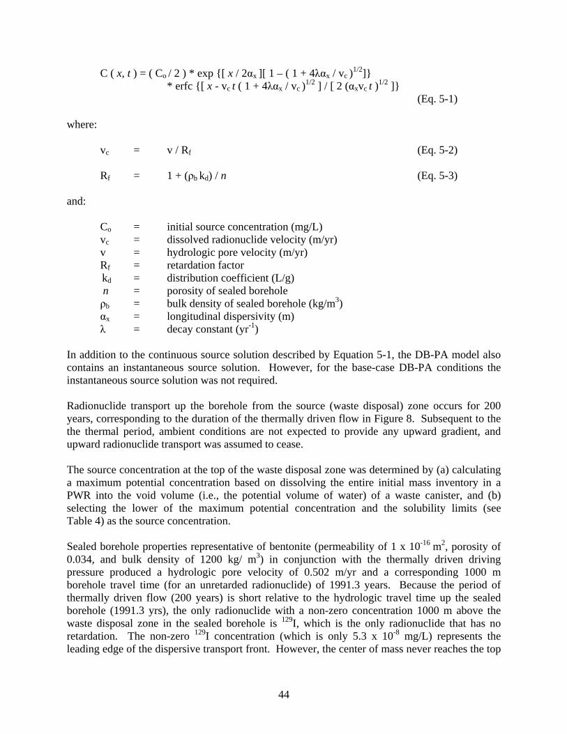
44
C ( x, t ) = ( Co / 2 ) * exp {[ x / 2αx ][ 1 – ( 1 + 4λαx / vc )1/2]}
* erfc {[ x - vc t ( 1 + 4λαx / vc )1/2 ] / [ 2 (αxvc t )
1/2 ]} (Eq. 5-1)
where:
vc = v / Rf (Eq. 5-2)
Rf = 1 + (ρb kd) / n (Eq. 5-3)
and: Co = initial source concentration (mg/L)
vc = dissolved radionuclide velocity (m/yr) v = hydrologic pore velocity (m/yr) Rf = retardation factor kd = distribution coefficient (L/g)
n = porosity of sealed borehole ρb = bulk density of sealed borehole (kg/m3) αx = longitudinal dispersivity (m) λ = decay constant (yr-1)
In addition to the continuous source solution described by Equation 5-1, the DB-PA model also contains an instantaneous source solution. However, for the base-case DB-PA conditions the instantaneous source solution was not required. Radionuclide transport up the borehole from the source (waste disposal) zone occurs for 200 years, corresponding to the duration of the thermally driven flow in Figure 8. Subsequent to the the thermal period, ambient conditions are not expected to provide any upward gradient, and upward radionuclide transport was assumed to cease. The source concentration at the top of the waste disposal zone was determined by (a) calculating a maximum potential concentration based on dissolving the entire initial mass inventory in a PWR into the void volume (i.e., the potential volume of water) of a waste canister, and (b) selecting the lower of the maximum potential concentration and the solubility limits (see Table 4) as the source concentration. Sealed borehole properties representative of bentonite (permeability of 1 x 10-16 m2, porosity of 0.034, and bulk density of 1200 kg/ m3) in conjunction with the thermally driven driving pressure produced a hydrologic pore velocity of 0.502 m/yr and a corresponding 1000 m borehole travel time (for an unretarded radionuclide) of 1991.3 years. Because the period of thermally driven flow (200 years) is short relative to the hydrologic travel time up the sealed borehole (1991.3 yrs), the only radionuclide with a non-zero concentration 1000 m above the waste disposal zone in the sealed borehole is 129I, which is the only radionuclide that has no retardation. The non-zero 129I concentration (which is only 5.3 x 10⁻⁸ mg/L) represents the leading edge of the dispersive transport front. However, the center of mass never reaches the top
45
of the 1000 m sealed section of the borehole because there is no further movement after 200 years. Accounting for the 8,000-year travel time for the radionuclides to reach the withdrawal well, results in a peak dose to the RMEI at 8,200 years. The DB-PA calculated results (dose to the RMEI) for all radionuclides at 8,200 years are shown in Table 6. The total dose to the RMEI at 8,200 years is 1.4 x 10⁻¹⁰ mrem/yr. The only contributor to the dose is 129I. These DB-PA results are based on several bounding and conservative assumptions, such as: all waste is assumed to instantly degrade and dissolve inside the waste canisters; all waste is assumed to be PWR assemblies; no credit is taken for sorption or decay along the saturated zone transport pathway from the sealed borehole to the withdrawal well. Thus, as a first approximation, more refined performance assessments may indicate lower doses, or later peak doses, or both, than established here. Other scenarios, with larger or longer flows, higher permeabilities, and different source configurations, would require refinements to the conceptual model.
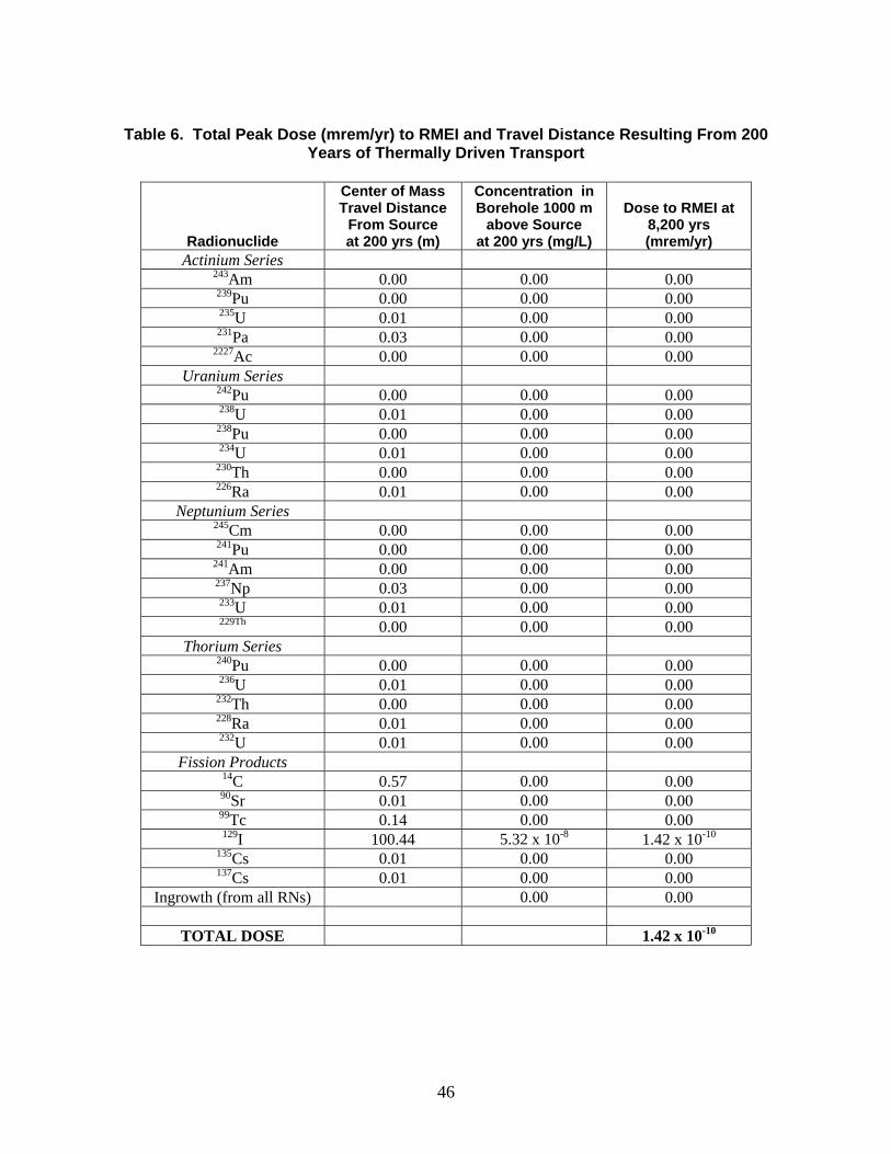
46
Table 6. Total Peak Dose (mrem/yr) to RMEI and Travel Distance Resulting From 200
Years of Thermally Driven Transport
Radionuclide
Center of Mass Travel Distance
From Source at 200 yrs (m)
Concentration in Borehole 1000 m
above Source at 200 yrs (mg/L)
Dose to RMEI at 8,200 yrs (mrem/yr)
Actinium Series 243Am 0.00 0.00 0.00 239Pu 0.00 0.00 0.00 235U 0.01 0.00 0.00 231Pa 0.03 0.00 0.00
2227Ac 0.00 0.00 0.00 Uranium Series
242Pu 0.00 0.00 0.00 238U 0.01 0.00 0.00
238Pu 0.00 0.00 0.00 234U 0.01 0.00 0.00
230Th 0.00 0.00 0.00 226Ra 0.01 0.00 0.00
Neptunium Series 245Cm 0.00 0.00 0.00 241Pu 0.00 0.00 0.00
241Am 0.00 0.00 0.00 237Np 0.03 0.00 0.00 233U 0.01 0.00 0.00 229Th 0.00 0.00 0.00
Thorium Series 240Pu 0.00 0.00 0.00 236U 0.01 0.00 0.00
232Th 0.00 0.00 0.00 228Ra 0.01 0.00 0.00 232U 0.01 0.00 0.00
Fission Products 14C 0.57 0.00 0.00 90Sr 0.01 0.00 0.00 99Tc 0.14 0.00 0.00 129I 100.44 5.32 x 10⁻⁸ 1.42 x 10⁻¹⁰
135Cs 0.01 0.00 0.00 137Cs 0.01 0.00 0.00
Ingrowth (from all RNs) 0.00 0.00
TOTAL DOSE 1.42 x 10⁻¹⁰

47
6. SUMMARY AND CONCLUSIONS 6.1. Preliminary Results Thermal, hydrologic, and geochemical calculations suggest that radionuclides in spent fuel emplaced in deep boreholes will experience little physical reason to leave the borehole/near borehole domain. The vast majority of radionuclides, and the fuel itself, will be thermodynamically stable and will therefore resist dissolution into borehole fluids, or movement into and through the adjacent rocks. Thermal-hydrologic calculations indicate that, except for an early window extending from the time of emplacement to ~ 150 years post-emplacement (in the borehole), and ~ 600 years (to the top of the basement), there will be no vertical fluid flow to transport radionuclides towards the surface. Vertical transport velocities in the early flow window will be between 0.1 (basement) and 0.7 (borehole) m/yr. This means that total vertical fluid movement in, and adjacent to, deep borehole disposal zones should not exceed roughly 100 meters. In the absence of advection, chemical diffusion cannot move radionuclides from boreholes through discontinuous, stagnant, and density-stratified waters over distances much greater than about 200 meters in the 1,000,000 years needed for the vast bulk of the radioactivity to decay away. Simplified and conservative performance assessment calculations indicate that radiological dose to a human receptor via the groundwater pathway would be limited to a single radionuclide (129I) and would be negligibly small, ~10 order of magnitude below current criteria. 6.2. Recommendations for Additional Work A more complete technical analysis of the deep borehole option requires a comprehensive evaluation of potentially relevant features, events, and processes, beginning with the preliminary list identified in Appendix B and expanding that list as appropriate. More detailed analyses should be performed to confirm that FEPs that have been excluded from this preliminary analysis do not significantly impact long-term performance. Future performance assessment modeling should consider all relevant release scenarios and pathways based on FEP analyses, rather than focusing on the single pathway considered in this report. FEP analyses and future iterations of performance assessment modeling will provide guidance regarding where resources should be focused to build confidence in the understanding of borehole disposal systems. Three specific areas for future research are noted here, based on preliminary analyses:
1. The coupled thermal-hydrologic-chemical-mechanical behavior of the borehole and disturbed region during the thermal pulse, and in the presence of density-stratified waters, should be modeled more accurately.
2. Additional consideration should be focused on the design and long-term performance
of deep seals. Calculated releases might be lowered even further from the already low values predicted above by development and deployment of sorbents that sorb/sequester 129I in the borehole, or in the seals. Layered bismuth hydroxide compounds have shown great promise for limiting 129I transport to the biosphere (Krumhansl et al., 2006). The performance of bismuth compounds must be verified
48
(and possibly optimized) under the temperature-salinity conditions that will prevail in deep boreholes.
3. Modeling of both the detailed thermal-hydrologic-chemical-mechanical behavior and
the full-system performance of multi-borehole arrays should be undertaken, consistent with an assumption that a regional borehole disposal facility could entail an array of 10-100 individual boreholes. Such investigations could elaborate on the potential for cross-hole effects, help determine minimum inter-holes distances, etc. In order to establish a better sense of the potential performance variability that might be expected in multiple implementations of borehole disposal fields, individual preliminary performance assessments should be performed for several specific regions. Specific regions could be identified based on the availability of pre-existing geohydrologic data for depths of ~ 3 - 5 kilometers.
In addition to the technical issues related to the post-closure performance of the deep borehole disposal system described above, several other topics that are beyond the scope of this report should be examined in further detail:
1. A more comprehensive and detailed cost analysis would provide a firmer basis for quantitative comparisons with other disposal system options;
2. A detailed description of the changes to legal and regulatory requirements for
implementation of deep borehole disposal would provide policymakers with a roadmap for necessary actions (specifically, consideration might be given to developing a risk-based standard); and
3. Detailed analyses of engineering systems and operational practices for waste
emplacement are needed to demonstrate the viability of the deep borehole disposal concept. Also, the advantages of applying deep borehole disposal in countries possessing smaller and/or non-fuel waste inventories should be explored further.
It is recommended that ultimately a full-scale pilot project be undertaken, perhaps with surrogate waste, in order to fully explore the viability of a borehole disposal concept. The scientific and engineering advances gained from a single pilot project, and the applicability to subsequent borehole disposal implementations, are in contrast to site-specific mined repositories and their unique site characterization demands with relatively little transferable knowledge to subsequent repositories. Given the potential for standardizing the borehole design, and thus the ready extension to multiple borehole facilities, a single pilot project could provide significant gains on the scientific and engineering issues needing to be resolved, enable the development of international standards, and accelerate the evaluation of the viability of deep borehole disposal of spent nuclear fuel and high-level radioactive waste.

49
7. REFERENCES ANDRA (Agence nationale pour la gestion des déchets radioactifs) (2005), Dossier 2005:
Argile. Tome: Safety Evaluation of a Geological Repository
Anderson, V. K. (2004). An evaluation of the feasibility of disposal of nuclear waste in very deep boreholes. Dept. of Nuclear Engineering. Cambridge, MA, MIT.
Bethke, C. M. and P. V. Brady (2000). "How the Kd approach undermines ground water cleanup." Ground Water 321: 435-442.
Crank, J. (1956). The Mathematics of Diffusion. Oxford University Press, New York.
DIANE Publishing Company (1995). Spent Nuclear Fuel Discharges from U.S. Reactors (1993), DIANE Publishing Company.
DOE (1996). Title 40 CFR Part 191 Compliance Certification Application for the Waste Isolation Pilot Plant DOE/CAO-1996-2184, U.S. Department of Energy, Waste Isolation Pilot Plant, Carlsbad Area Office, Carlsbad, NM.
DOE (2004). Title 40 CFR Part 191 Compliance Recertification Application for the Waste Isolation Pilot Plant DOE/WIPP 2004-3231, U.S. Department of Energy Waste Isolation Pilot Plant, Carlsbad Field Office, Carlsbad, NM.
DOE (2008a). Analysis of the Total System Life Cycle Cost of the Civilian Radioactive Waste Management Program, Fiscal Year 2007, DOE/RW-0591.
DOE (2008b). Yucca Mountain License Application. DOE/RW-0753 Rev. 0.
Gibb, F. G. F., N. A. McTaggart, et al. (2008). "High-density suport matrices: Key to the deep borehole disposal of spent nuclear fuel." J. of Nuclear Materials 374: 370-377.
Heiken, G., G. Woldegabriel, R. Morley, H. Plannerer, and J. Rowley (1996). Disposition of excess weapon plutonium in deep boreholes – site selection handbook. Los Alamos, NM, Los Alamos National Laboratory.
Hoag, C. I. (2006). Canister design for deep borehole disposal of nuclear waste. Dept of Nuclear Engineering. Cambridge, MA, MIT.
Japan Nuclear Cycle Development Institute (2000). The geological environment of Japan. In Geological Isolation Research Project, Overview Report H12, English version.
Juhlin, C. and H. Sandstedt (1989). Storage of nuclear waste in very deep boreholes: Feasibility study and assessment of economic potential. Part I: Geological considerations. Part II: Overall facility plan and cost analysis., Svensk Karnbranslehantering AB.
Krumhansl, J. L., J. D. Pless, et al. (2006). Yucca Mountain Project Getter Program Results (Year 1): I-129 and Other Anions of Concern: SAND2006-3869.
Langmuir, D. L. (1996). Aqueous environmental geochemistry. Upper Saddle River, NJ, Prentice-Hall.
McKinley, I. G. and A. Scholtis (1993). "A comparison of radionuclide sorption databases used in recent performance assessments." Journal of Contaminant Hydrology 13: 347-363.
50
MIT (2006). The Future of Geothermal Energy. Cambridge, MA, MIT.
Mitchell, J. K. (1993). Fundamentals of Soil Behavior. 2nd Ed. . New York, NY, John Wiley & Sons, Inc.
National Academy of Sciences (1957). The Disposal of Radioactive Waste on Land.
O’Brien, M.T, L.H. Cohen, T.N. Narasimhan, T.L. Simkin, H.A. Wollenberg, W.F. Brace, S. Green, H.P. Platt, (1979), The very deep hole concept: evaluation of an alternative for nuclear waste disposal, Berkeley, CA, Lawrence Berkeley Laboratory, LBL- 7089.
Polsky, Y., L. Capuano, et al. (2008). Enhanced Geothermal Systems (EGS) Well Construction Technology Evaluation Report, Sandia Report SAND2008-7866.
Rechard, R. P., L. E. Sanchez, et al. (2001). "Unfavorable Conditions for Nuclear Criticality Following Disposal of Transuranic Waste at the Waste Isolation Pilot Plant." Nuclear Technology 136: 99-129.
Rechard, R. P., L. C. Sanchez, et al. (2003). "Consideration of Nuclear Criticality when Disposing Highly Enriched Spent Nuclear Fuel in Unsaturated Tuff—I: Nuclear Criticality Constraints." Nuclear Technology 144: 201-221.
Sandia National Laboratories (2008a). "Total System Performance Assessment Model/Analysis for the License Application.” MDL-WIS-PA-000005 REV 00 AD 01.
Sandia National Laboratories (2008b), “Features, Events, and Processes for the Total System Performance Assessment: Analyses”ANL-WIS-MD-0000027 REV 00,
Van der Leeden, F., F. L. Troise, and D. K. Todd, (1990). The Water Encyclopedia –Second Edition, Geraghty and Miller Groundwater Series.
Van Geet, M. e. a. (2007). "Efficiency of a Borehole Seal by Means of Pre-Compacted Bentonite Blocks." Physics and Chemistry of the Earth, Parts A/B/C 32(1-7): 123-134.
Wing, N. R. and G. E. Gee (1994). "Quest for the Perfect Cap." Civil Engineering 64(10): 38041.
Woodward-Clyde Consultants (1983). Very deep hole systems engineering studies. Columbus, OH, ONWI.
Zyvoloski, G. A., B. A. Robinson, et al. (1997). Summary of models and methods for FEHM application – A finite element heat and mass transfer code. Los Alamos National Laboratory Report LA-13307-MS.
51
APPENDIX A: U.S. HLW AND SNF INVENTORY Evaluation of the deep borehole disposal concept in this report is based on estimates of current and projected future quantities of high-level radioactive waste and spent nuclear fuel in the U.S. In 2007, DOE estimated that 109,300 metric tons heavy metal (MTHM) of high-level waste and spent nuclear fuel in the U.S. will ultimately need to be stored (DOE Office of Public Affairs, August 5, 2008). This inventory consists of 70,000 MTHM that is included in the Yucca Mountain license application, with the remainder that will need to be disposed of from future production. The inventory includes commercial spent nuclear fuel (CSNF), DOE spent nuclear fuel (DSNF), and high-level waste glass (HLWG). The inventory consists of actinide elements in several radionuclide decay chains (Figure 14) along with a number of fission products. The 70,000 MTHM Yucca Mountain inventory is predominantly (about 70%) CSNF, which in turn consists of spent fuel assemblies from pressurized water reactors (PWRs) and boiling water reactors (BWRs). A representative inventory, showing the important actinide elements from Figure 14 and the important fission products, for a single Yucca Mountain waste package is provided in Table 7. The 31-radionuclide inventory is shown for an initial time (either 2030 or 2067 depending on waste type) and aged to a common year, 2117, about 100 years from the present. Note that this table actually represents two different types of waste packages: a CSNF waste package that contains the CSNF inventory (a single CSNF waste package would contain either 21 PWR assemblies or 44 BWR assemblies); and a codisposal waste package that combines the DSNF and HLWG inventory. Also, note that the inventories in Table 7 do not include any Mixed Oxide (MOX) fuel or Lanthanide Borosilicate (LaBS) waste. For the purposes of discussing and characterizing the waste for deep borehole disposal, the relative radionuclide inventories for CSNF shown in Table 7 are considered representative of the entire US HLW and SNF inventory. The other waste streams (DSNF and HLWG) contains similar relative radionuclide inventories (Table 7) as the CSNF waste stream. By weight, CSNF is about 97% 238U, with contributions of 0.3-0.8% from 235U, 236U, 239Pu, and 240Pu. All other radionuclides contribute less than 0.1%. Figure 15 shows the relative contributions of the 31 radionuclides by activity (in curies), which is a more direct indicator of their potential effect on dose. Note that Figure 15 includes all waste (not just CSNF), but the relative contributions are likely to be the same. The change in importance of the various radionuclides over time is indicative of the effects decay and ingrowth. The same information is tabulated in Table 8, which also shows the decline in total activity over time.
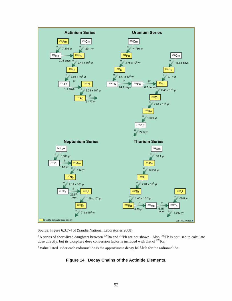
52
Source: Figure 6.3.7-4 of (Sandia National Laboratories 2008). a A series of short-lived daughters between 226Ra and 210Pb are not shown. Also, 210Pb is not used to calculate dose directly, but its biosphere dose conversion factor is included with that of 226Ra. b Value listed under each radionuclide is the approximate decay half-life for the radionuclide.
Figure 14. Decay Chains of the Actinide Elements.
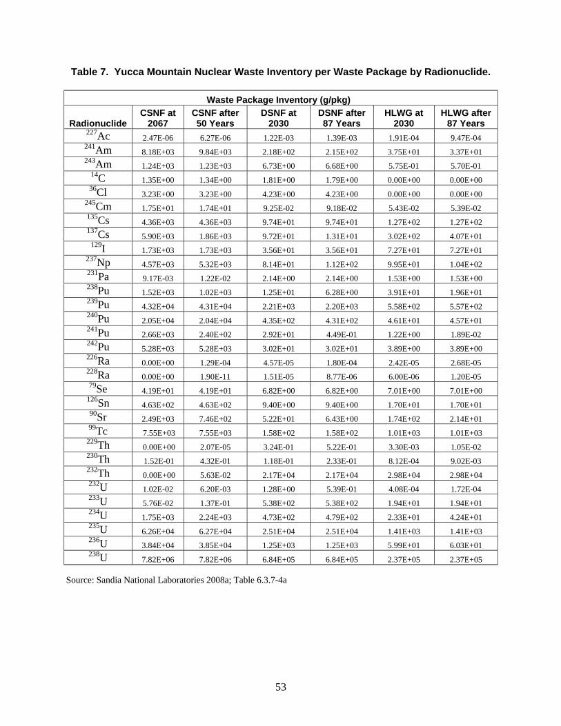
53
Table 7. Yucca Mountain Nuclear Waste Inventory per Waste Package by Radionuclide.
Waste Package Inventory (g/pkg)
Radionuclide CSNF at
2067 CSNF after 50 Years
DSNF at 2030
DSNF after 87 Years
HLWG at 2030
HLWG after 87 Years
227Ac 2.47E-06 6.27E-06 1.22E-03 1.39E-03 1.91E-04 9.47E-04 241Am 8.18E+03 9.84E+03 2.18E+02 2.15E+02 3.75E+01 3.37E+01 243Am 1.24E+03 1.23E+03 6.73E+00 6.68E+00 5.75E-01 5.70E-01
14C 1.35E+00 1.34E+00 1.81E+00 1.79E+00 0.00E+00 0.00E+00 36Cl 3.23E+00 3.23E+00 4.23E+00 4.23E+00 0.00E+00 0.00E+00
245Cm 1.75E+01 1.74E+01 9.25E-02 9.18E-02 5.43E-02 5.39E-02 135Cs 4.36E+03 4.36E+03 9.74E+01 9.74E+01 1.27E+02 1.27E+02 137Cs 5.90E+03 1.86E+03 9.72E+01 1.31E+01 3.02E+02 4.07E+01
129I 1.73E+03 1.73E+03 3.56E+01 3.56E+01 7.27E+01 7.27E+01 237Np 4.57E+03 5.32E+03 8.14E+01 1.12E+02 9.95E+01 1.04E+02 231Pa 9.17E-03 1.22E-02 2.14E+00 2.14E+00 1.53E+00 1.53E+00 238Pu 1.52E+03 1.02E+03 1.25E+01 6.28E+00 3.91E+01 1.96E+01 239Pu 4.32E+04 4.31E+04 2.21E+03 2.20E+03 5.58E+02 5.57E+02 240Pu 2.05E+04 2.04E+04 4.35E+02 4.31E+02 4.61E+01 4.57E+01 241Pu 2.66E+03 2.40E+02 2.92E+01 4.49E-01 1.22E+00 1.89E-02 242Pu 5.28E+03 5.28E+03 3.02E+01 3.02E+01 3.89E+00 3.89E+00 226Ra 0.00E+00 1.29E-04 4.57E-05 1.80E-04 2.42E-05 2.68E-05 228Ra 0.00E+00 1.90E-11 1.51E-05 8.77E-06 6.00E-06 1.20E-05 79Se 4.19E+01 4.19E+01 6.82E+00 6.82E+00 7.01E+00 7.01E+00
126Sn 4.63E+02 4.63E+02 9.40E+00 9.40E+00 1.70E+01 1.70E+01 90Sr 2.49E+03 7.46E+02 5.22E+01 6.43E+00 1.74E+02 2.14E+01 99Tc 7.55E+03 7.55E+03 1.58E+02 1.58E+02 1.01E+03 1.01E+03
229Th 0.00E+00 2.07E-05 3.24E-01 5.22E-01 3.30E-03 1.05E-02 230Th 1.52E-01 4.32E-01 1.18E-01 2.33E-01 8.12E-04 9.02E-03 232Th 0.00E+00 5.63E-02 2.17E+04 2.17E+04 2.98E+04 2.98E+04 232U 1.02E-02 6.20E-03 1.28E+00 5.39E-01 4.08E-04 1.72E-04 233U 5.76E-02 1.37E-01 5.38E+02 5.38E+02 1.94E+01 1.94E+01 234U 1.75E+03 2.24E+03 4.73E+02 4.79E+02 2.33E+01 4.24E+01 235U 6.26E+04 6.27E+04 2.51E+04 2.51E+04 1.41E+03 1.41E+03 236U 3.84E+04 3.85E+04 1.25E+03 1.25E+03 5.99E+01 6.03E+01 238U 7.82E+06 7.82E+06 6.84E+05 6.84E+05 2.37E+05 2.37E+05
Source: Sandia National Laboratories 2008a; Table 6.3.7-4a
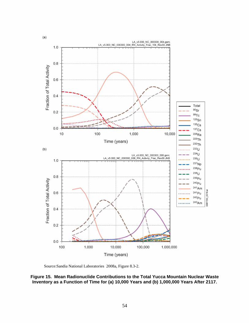
54
Source:Sandia National Laboratories 2008a, Figure 8.3-2. Figure 15. Mean Radionuclide Contributions to the Total Yucca Mountain Nuclear Waste Inventory as a Function of Time for (a) 10,000 Years and (b) 1,000,000 Years After 2117.

55
Table 8. Decay of Total Yucca Mountain Nuclear Waste Inventory as a Function of Time and Dominant Contributors to Total Curie Inventory.
Time After
Closure, 2117 (yrs)
Percent of Total Initial Curie Inventory
Major Contributors to Total Inventory
at Time after Closure
0 100.00
137Cs (46%), 90Sr (29%),
241Am (10%)
10 81.2
137Cs (45%), 90Sr (28%),
241Am (12%)
100 20.75
241Am (41%), 137Cs (22 %),
90Sr (13%), 238Pu (11%))
1,000 4.20 241Am (48%),
240Pu (29%), 239Pu (19%) 10,000 1.18 239Pu-239 (52%), 240Pu (40%)
100,000 0.10
239Pu-239 (46%), 99Tc-99 (27%)
500,000 0.03
99Tc-99 (26%), 229Th-229 (9%), 230Th (9%), 226Ra-226 (9%), 233U (9%),
237Np-237 (9%), 242Pu (8%), 234U-234 (7%)
1,000,000 0.02
233U-233 (15%), 229Th (15%), 237Np-237 (14%),
99Tc-99 (9%), 230Th (7%), 226Ra-226 (7%), 135Cs (7%),
236U-236 (6%), 242Pu (6%)
Source: Table 8.3-1 of (Sandia National Laboratories 2008) At early time (the first few hundred years after emplacement) the radionuclides with the highest activity are all short-lived (half-lives less than 500 years): 137Cs, 90Sr, 241Am, and 238Pu. From about 100 years to 1,500 years after emplacement, 241Am is the largest contributor to the total activity. Subsequent to that, moderate half-life radionuclides become more important. 240Pu (half-life of 6,560 years) is the largest contributor to total activity from about 1,500 years to 7,000 years after emplacement, then 239Pu (half-life of 24,100 years) becomes the largest contributor until about 100,000 years after emplacement. At very long times (greater than 100,000 years after emplacement), the following long-lived radionuclides become most important to total activity: 99Tc, 242Pu, 237Np, 234U, 230Th, 226Ra, 233U, 229Th, 135Cs, and 236U. Table 8 shows that the total activity (in curies) of the inventory decays to about 20% of the initial activity after 100 years, to about 4% after 1,000 years, and to about 1% of the initial activity after 10,000 years. Roughly 1000 years is required before the total radioactivity in CSNF would decay to the background level of a 0.2% U ore body. The radiation in un-processed spent fuel requires roughly 10,000 years to decay to the background levels of an ore body (Langmuir 1996).

56
APPENDIX B: COMPARISON OF DEEP BOREHOLE DISPOSAL AND YMP FEPS
Table B-1. Yucca Mountain Project Features, Events, and Processes List and Screening
Decisions Listed by FEP Number. (based on: Sandia National Laboratories 2008b, Table 7.1). A “?” denotes a lower level of confidence in the preliminary analysis.
FEP Number FEP Name
YMP Screening Decision
Likely DBD Decision
Estimated DBD Level of Effort
0.1.02.00.0A Timescales of Concern Included Include 1 0.1.03.00.0A Spatial Domain of Concern Included Include 1 0.1.09.00.0A Regulatory Requirements and Exclusions Included Include 3
Regulations and laws will need to be
revised 0.1.10.00.0A Model and Data Issues Included Include 1 1.1.01.01.0A Open Site Investigation Boreholes Excluded Exclude 1 1.1.01.01.0B Influx Through Holes Drilled in Drift Wall or
Crown Excluded Exclude (NA) 1
1.1.02.00.0A Chemical Effects of Excavation and Construction in EBS
Excluded Exclude 2
1.1.02.00.0B Mechanical Effects of Excavation and Construction in EBS
Excluded Include 2
1.1.02.01.0A Site Flooding (During Construction and Operation)
Excluded Exclude 1
1.1.02.02.0A Preclosure Ventilation Included Exclude (NA) 1 1.1.02.03.0A Undesirable Materials Left Excluded Exclude (NA) 2 1.1.03.01.0A Error in Waste Emplacement Excluded Exclude 3
Need to consider the emplacement
that may get stuck halfway down. Also need to
consider canisters that are crushed by overlying canisters
1.1.03.01.0B Error in Backfill Emplacement Excluded Include? Maybe be difficult to ensure that
backfill is emplaced uniformly, may be simplest to include FEP and take no
credit for backfill1 1.1.04.01.0A Incomplete Closure Excluded Exclude 2 1.1.05.00.0A Records and Markers for the Repository Excluded Exclude
(regulatory) 1
1.1.07.00.0A Repository Design Included Include 1 1.1.08.00.0A Inadequate Quality Control and Deviations
from Design Excluded Exclude
(regulatory or low
consequence)
1
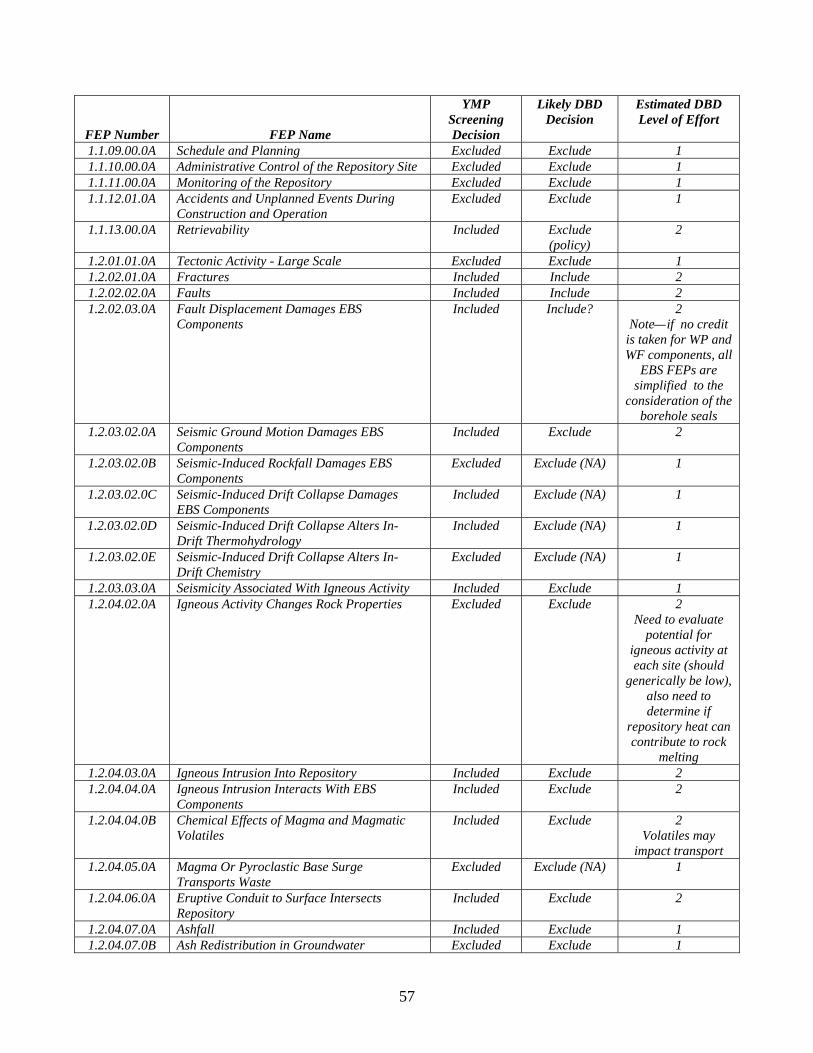
57
FEP Number FEP Name
YMP Screening Decision
Likely DBD Decision
Estimated DBD Level of Effort
1.1.09.00.0A Schedule and Planning Excluded Exclude 1 1.1.10.00.0A Administrative Control of the Repository Site Excluded Exclude 1 1.1.11.00.0A Monitoring of the Repository Excluded Exclude 1 1.1.12.01.0A Accidents and Unplanned Events During
Construction and Operation Excluded Exclude 1
1.1.13.00.0A Retrievability Included Exclude (policy)
2
1.2.01.01.0A Tectonic Activity - Large Scale Excluded Exclude 1 1.2.02.01.0A Fractures Included Include 2 1.2.02.02.0A Faults Included Include 2 1.2.02.03.0A Fault Displacement Damages EBS
Components Included Include? 2
Note—if no credit is taken for WP and WF components, all
EBS FEPs are simplified to the
consideration of the borehole seals
1.2.03.02.0A Seismic Ground Motion Damages EBS Components
Included Exclude 2
1.2.03.02.0B Seismic-Induced Rockfall Damages EBS Components
Excluded Exclude (NA) 1
1.2.03.02.0C Seismic-Induced Drift Collapse Damages EBS Components
Included Exclude (NA) 1
1.2.03.02.0D Seismic-Induced Drift Collapse Alters In-Drift Thermohydrology
Included Exclude (NA) 1
1.2.03.02.0E Seismic-Induced Drift Collapse Alters In-Drift Chemistry
Excluded Exclude (NA) 1
1.2.03.03.0A Seismicity Associated With Igneous Activity Included Exclude 1 1.2.04.02.0A Igneous Activity Changes Rock Properties Excluded Exclude 2
Need to evaluate potential for
igneous activity at each site (should
generically be low), also need to determine if
repository heat can contribute to rock
melting 1.2.04.03.0A Igneous Intrusion Into Repository Included Exclude 2 1.2.04.04.0A Igneous Intrusion Interacts With EBS
Components Included Exclude 2
1.2.04.04.0B Chemical Effects of Magma and Magmatic Volatiles
Included Exclude 2 Volatiles may
impact transport 1.2.04.05.0A Magma Or Pyroclastic Base Surge
Transports Waste Excluded Exclude (NA) 1
1.2.04.06.0A Eruptive Conduit to Surface Intersects Repository
Included Exclude 2
1.2.04.07.0A Ashfall Included Exclude 1 1.2.04.07.0B Ash Redistribution in Groundwater Excluded Exclude 1

58
FEP Number FEP Name
YMP Screening Decision
Likely DBD Decision
Estimated DBD Level of Effort
1.2.04.07.0C Ash Redistribution Via Soil and Sediment Transport
Included Exclude 1
1.2.05.00.0A Metamorphism Excluded Exclude 2 Repository heat
may create metamorphic
conditions 1.2.06.00.0A Hydrothermal Activity Excluded Exclude 3
Repository heat may create local
hydrothermal activity
1.2.07.01.0A Erosion/Denudation Excluded Exclude 1 1.2.07.02.0A Deposition Excluded Exclude 1 1.2.08.00.0A Diagenesis Excluded Exclude 2 1.2.09.00.0A Salt Diapirism and Dissolution Excluded Exclude 1 1.2.09.01.0A Diapirism Excluded Exclude 2
Need to demonstrate that
repository heat will not generate local
diapirism 1.2.09.02.0A Large-Scale Dissolution Excluded Exclude 1 1.2.10.01.0A Hydrologic Response to Seismic Activity Excluded Exclude 1 1.2.10.02.0A Hydrologic Response to Igneous Activity Excluded Exclude 2 1.3.01.00.0A Climate Change Included Exclude 1 1.3.04.00.0A Periglacial Effects Excluded Include 1 1.3.05.00.0A Glacial and Ice Sheet Effect Excluded Include 2
Need to consider fluid pressure
effects of future ice sheet loading
1.3.07.01.0A Water Table Decline Excluded Exclude 1 1.3.07.02.0A Water Table Rise Affects SZ Included Exclude 1 1.3.07.02.0B Water Table Rise Affects UZ Included Exclude 1
All UZ FEPs are simplified
1.4.01.00.0A Human Influences on Climate Excluded Exclude 1 1.4.01.01.0A Climate Modification Increases Recharge Included Exclude 1 1.4.01.02.0A Greenhouse Gas Effects Excluded Exclude 1 1.4.01.03.0A Acid Rain Excluded Exclude 1 1.4.01.04.0A Ozone Layer Failure Excluded Exclude 1 1.4.02.01.0A Deliberate Human Intrusion Excluded Exclude 1 1.4.02.02.0A Inadvertent Human Intrusion Included Exclude 1 (requires
regulatory change) 1.4.02.03.0A Igneous Event Precedes Human Intrusion Excluded Exclude 1 1.4.02.04.0A Seismic Event Precedes Human Intrusion Excluded Exclude 1 1.4.03.00.0A Unintrusive Site Investigation Excluded Exclude 1 1.4.04.00.0A Drilling Activities (Human Intrusion) Included Exclude 1 1.4.04.01.0A Effects of Drilling Intrusion Included Exclude 1 1.4.05.00.0A Mining and Other Underground Activities Excluded Exclude 1
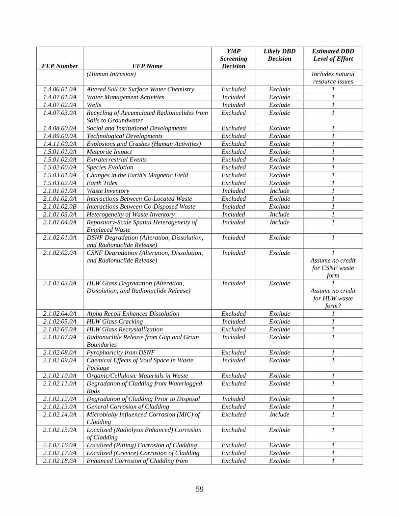
59
FEP Number FEP Name
YMP Screening Decision
Likely DBD Decision
Estimated DBD Level of Effort
(Human Intrusion) Includes natural resource issues
1.4.06.01.0A Altered Soil Or Surface Water Chemistry Excluded Exclude 1 1.4.07.01.0A Water Management Activities Included Exclude 1 1.4.07.02.0A Wells Included Exclude 1 1.4.07.03.0A Recycling of Accumulated Radionuclides from
Soils to Groundwater Excluded Exclude 1
1.4.08.00.0A Social and Institutional Developments Excluded Exclude 1 1.4.09.00.0A Technological Developments Excluded Exclude 1 1.4.11.00.0A Explosions and Crashes (Human Activities) Excluded Exclude 1 1.5.01.01.0A Meteorite Impact Excluded Exclude 1 1.5.01.02.0A Extraterrestrial Events Excluded Exclude 1 1.5.02.00.0A Species Evolution Excluded Exclude 1 1.5.03.01.0A Changes in the Earth's Magnetic Field Excluded Exclude 1 1.5.03.02.0A Earth Tides Excluded Exclude 1 2.1.01.01.0A Waste Inventory Included Include 1 2.1.01.02.0A Interactions Between Co-Located Waste Excluded Exclude 1 2.1.01.02.0B Interactions Between Co-Disposed Waste Included Exclude 1 2.1.01.03.0A Heterogeneity of Waste Inventory Included Include 1 2.1.01.04.0A Repository-Scale Spatial Heterogeneity of
Emplaced Waste Included Include 1
2.1.02.01.0A DSNF Degradation (Alteration, Dissolution, and Radionuclide Release)
Included Exclude 1
2.1.02.02.0A CSNF Degradation (Alteration, Dissolution, and Radionuclide Release)
Included Exclude 1 Assume no credit for CSNF waste
form 2.1.02.03.0A HLW Glass Degradation (Alteration,
Dissolution, and Radionuclide Release) Included Exclude 1
Assume no credit for HLW waste
form? 2.1.02.04.0A Alpha Recoil Enhances Dissolution Excluded Exclude 1 2.1.02.05.0A HLW Glass Cracking Included Exclude 1 2.1.02.06.0A HLW Glass Recrystallization Excluded Exclude 1 2.1.02.07.0A Radionuclide Release from Gap and Grain
Boundaries Included Exclude 1
2.1.02.08.0A Pyrophoricity from DSNF Excluded Exclude 1 2.1.02.09.0A Chemical Effects of Void Space in Waste
Package Included Exclude 1
2.1.02.10.0A Organic/Cellulosic Materials in Waste Excluded Exclude 1 2.1.02.11.0A Degradation of Cladding from Waterlogged
Rods Excluded Exclude 1
2.1.02.12.0A Degradation of Cladding Prior to Disposal Included Exclude 1 2.1.02.13.0A General Corrosion of Cladding Excluded Exclude 1 2.1.02.14.0A Microbially Influenced Corrosion (MIC) of
Cladding Excluded Include 1
2.1.02.15.0A Localized (Radiolysis Enhanced) Corrosion of Cladding
Excluded Exclude 1
2.1.02.16.0A Localized (Pitting) Corrosion of Cladding Excluded Exclude 1 2.1.02.17.0A Localized (Crevice) Corrosion of Cladding Excluded Exclude 1 2.1.02.18.0A Enhanced Corrosion of Cladding from Excluded Exclude 1
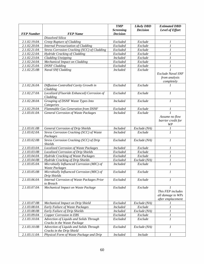
60
FEP Number FEP Name
YMP Screening Decision
Likely DBD Decision
Estimated DBD Level of Effort
Dissolved Silica 2.1.02.19.0A Creep Rupture of Cladding Excluded Exclude 1 2.1.02.20.0A Internal Pressurization of Cladding Excluded Exclude 1 2.1.02.21.0A Stress Corrosion Cracking (SCC) of Cladding Excluded Exclude 1 2.1.02.22.0A Hydride Cracking of Cladding Excluded Exclude 1 2.1.02.23.0A Cladding Unzipping Included Exclude 1 2.1.02.24.0A Mechanical Impact on Cladding Excluded Exclude 1 2.1.02.25.0A DSNF Cladding Excluded Exclude 1 2.1.02.25.0B Naval SNf Cladding Included Exclude 1
Exclude Naval SNF from analysis
completely 2.1.02.26.0A Diffusion-Controlled Cavity Growth in
Cladding Excluded Exclude 1
2.1.02.27.0A Localized (Fluoride Enhanced) Corrosion of Cladding
Excluded Exclude 1
2.1.02.28.0A Grouping of DSNF Waste Types Into Categories
Included Exclude 1
2.1.02.29.0A Flammable Gas Generation from DSNF Excluded Exclude 1 2.1.03.01.0A General Corrosion of Waste Packages Included Exclude 1
Assume no flow barrier credit for
WP 2.1.03.01.0B General Corrosion of Drip Shields Included Exclude (NA) 1 2.1.03.02.0A Stress Corrosion Cracking (SCC) of Waste
Packages Included Exclude 1
2.1.03.02.0B Stress Corrosion Cracking (SCC) of Drip Shields
Excluded Exclude (NA) 1
2.1.03.03.0A Localized Corrosion of Waste Packages Included Exclude 1 2.1.03.03.0B Localized Corrosion of Drip Shields Excluded Exclude 1 2.1.03.04.0A Hydride Cracking of Waste Packages Excluded Exclude 1 2.1.03.04.0B Hydride Cracking of Drip Shields Excluded Exclude (NA) 1 2.1.03.05.0A Microbially Influenced Corrosion (MIC) of
Waste Packages Included Exclude 1
2.1.03.05.0B Microbially Influenced Corrosion (MIC) of Drip Shields
Excluded Exclude 1
2.1.03.06.0A Internal Corrosion of Waste Packages Prior to Breach
Excluded Exclude 1
2.1.03.07.0A Mechanical Impact on Waste Package Excluded Exclude 1 This FEP includes all damage to WPs after emplacement
2.1.03.07.0B Mechanical Impact on Drip Shield Excluded Exclude (NA) 1 2.1.03.08.0A Early Failure of Waste Packages Included Exclude 1 2.1.03.08.0B Early Failure of Drip Shields Included Exclude (NA) 1 2.1.03.09.0A Copper Corrosion in EBS Excluded Exclude 1 2.1.03.10.0A Advection of Liquids and Solids Through
Cracks in the Waste Package Excluded Exclude 1
2.1.03.10.0B Advection of Liquids and Solids Through Cracks in the Drip Shield
Excluded Exclude (NA) 1
2.1.03.11.0A Physical Form of Waste Package and Drip Included Include 1

61
FEP Number FEP Name
YMP Screening Decision
Likely DBD Decision
Estimated DBD Level of Effort
Shield 2.1.04.01.0A Flow in the Backfill Excluded Include 1
Include FEPs that degrade backfill by assuming no credit due to difficulty in
ensuring full emplacement
2.1.04.02.0A Chemical Properties and Evolution of Backfill
Excluded Include 1
2.1.04.03.0A Erosion or Dissolution of Backfill Excluded Include 1 2.1.04.04.0A Thermal-Mechanical Effects of Backfill Excluded Include 1 2.1.04.05.0A Thermal-Mechanical Properties and
Evolution of Backfill Excluded Include 1
2.1.04.09.0A Radionuclide Transport in Backfill Excluded Exclude 1 Exclude beneficial transport effects of backfill because of
difficulty in ensuring full emplacement
2.1.05.01.0A Flow Through Seals (Access Ramps and Ventilation Shafts)
Excluded Include 3
2.1.05.02.0A Radionuclide Transport Through Seals Excluded Include 3 2.1.05.03.0A Degradation of Seals Excluded Include 3 2.1.06.01.0A Chemical Effects of Rock Reinforcement and
Cementitious Materials in EBS Excluded Include
(Seals are EBS, so one
entire release pathway to RMEI is in
EBS)
3
2.1.06.02.0A Mechanical Effects of Rock Reinforcement Materials in EBS
Excluded Include 3 What happens to borehole seal as casing degrades?
2.1.06.04.0A Flow Through Rock Reinforcement Materials in EBS
Excluded Exclude 1
2.1.06.05.0A Mechanical Degradation of Emplacement Pallet
Excluded Exclude (NA) 1
2.1.06.05.0B Mechanical Degradation of Invert Excluded Exclude (NA) 1 2.1.06.05.0C Chemical Degradation of Emplacement Pallet Included Exclude (NA) 1 2.1.06.05.0D Chemical Degradation of Invert Excluded Exclude (NA) 1 2.1.06.06.0A Effects of Drip Shield on Flow Included Exclude (NA) 1 2.1.06.06.0B Oxygen Embrittlement of Drip Shields Excluded Exclude (NA) 1 2.1.06.07.0A Chemical Effects at EBS Component
Interfaces Excluded Include? 2
2.1.06.07.0B Mechanical Effects at EBS Component Interfaces
Excluded Include 3
2.1.07.01.0A Rockfall Excluded Exclude 1 2.1.07.02.0A Drift Collapse Excluded Exclude 1
If drift = borehole,

62
FEP Number FEP Name
YMP Screening Decision
Likely DBD Decision
Estimated DBD Level of Effort
then this is a potentially significant
operational FEP 2.1.07.04.0A Hydrostatic Pressure on Waste Package Excluded Include 2 2.1.07.04.0B Hydrostatic Pressure on Drip Shield Excluded Exclude (NA) 1 2.1.07.05.0A Creep of Metallic Materials in the Waste
Package Excluded Exclude 1
2.1.07.05.0B Creep of Metallic Materials in the Drip Shield
Excluded Exclude (NA) 1
2.1.07.06.0A Floor Buckling Excluded Exclude 1 2.1.08.01.0A Water Influx at the Repository Included Include 1 2.1.08.01.0B Effects of Rapid Influx into the Repository Excluded Exclude 1 2.1.08.02.0A Enhanced Influx at the Repository Included Exclude 1 2.1.08.03.0A Repository Dry-Out Due to Waste Heat Included Include 1 2.1.08.04.0A Condensation Forms on Roofs of Drifts
(Drift-Scale Cold Traps) Included Exclude 1
2.1.08.04.0B Condensation Forms at Repository Edges (Repository-Scale Cold Traps)
Included Exclude 1
2.1.08.05.0A Flow Through Invert Included Exclude (NA) 1 2.1.08.06.0A Capillary Effects (Wicking) in EBS Included Exclude 1 2.1.08.07.0A Unsaturated Flow in the EBS Included Exclude 1 2.1.08.09.0A Saturated Flow in the EBS Excluded Include 3 2.1.08.11.0A Repository Resaturation Due to Waste
Cooling Included Include 1
2.1.08.12.0A Induced Hydrologic Changes in Invert Excluded Exclude (NA) 1 2.1.08.14.0A Condensation on Underside of Drip Shield Excluded Exclude (NA) 1 2.1.08.15.0A Consolidation of EBS Components Excluded Include 3 2.1.09.01.0A Chemical Characteristics of Water in Drifts Included Include 3 2.1.09.01.0B Chemical Characteristics of Water in Waste
Package Included Include 3
2.1.09.02.0A Chemical Interaction With Corrosion Products
Included Include 3
2.1.09.03.0A Volume Increase of Corrosion Products Impacts Cladding
Excluded Exclude 1
2.1.09.03.0B Volume Increase of Corrosion Products Impacts Waste Package
Excluded Exclude 1
2.1.09.03.0C Volume Increase of Corrosion Products Impacts Other EBS Components
Excluded Exclude 1
2.1.09.04.0A Radionuclide Solubility, Solubility Limits, and Speciation in the Waste Form and EBS
Included Include 3
2.1.09.05.0A Sorption of Dissolved Radionuclides in EBS Included Include 3 2.1.09.06.0A Reduction-Oxidation Potential in Waste
Package Included Include 1
2.1.09.06.0B Reduction-Oxidation Potential in Drifts Included Include 1 2.1.09.07.0A Reaction Kinetics in Waste Package Included Exclude 2 2.1.09.07.0B Reaction Kinetics in Drifts Included Exclude 2 2.1.09.08.0A Diffusion of Dissolved Radionuclides in EBS Included Include 3 2.1.09.08.0B Advection of Dissolved Radionuclides in EBS Included Include 3 2.1.09.09.0A Electrochemical Effects in EBS Excluded Exclude 1 2.1.09.10.0A Secondary Phase Effects on Dissolved Excluded Include 2

63
FEP Number FEP Name
YMP Screening Decision
Likely DBD Decision
Estimated DBD Level of Effort
Radionuclide Concentrations 2.1.09.11.0A Chemical Effects of Waste-Rock Contact Excluded Include 2 2.1.09.12.0A Rind (Chemically Altered Zone) Forms in the
Near-Field Excluded Exclude 2
2.1.09.13.0A Complexation in EBS Excluded Exclude 2 2.1.09.15.0A Formation of True (Intrinsic) Colloids in EBS Excluded Exclude 1 2.1.09.16.0A Formation of Pseudo-Colloids (Natural) in
EBS Included Exclude 1
2.1.09.17.0A Formation of Pseudo-Colloids (Corrosion Product) in EBS
Included Exclude 1
2.1.09.18.0A Formation of Microbial Colloids in EBS Excluded Exclude 1 2.1.09.19.0A Sorption of Colloids in EBS Excluded Exclude 1 2.1.09.19.0B Advection of Colloids in EBS Included Exclude 1 2.1.09.20.0A Filtration of Colloids in EBS Excluded Exclude 1 2.1.09.21.0A Transport of Particles Larger Than Colloids
in EBS Excluded Exclude 1
2.1.09.21.0B Transport of Particles Larger Than Colloids in the SZ
Excluded Exclude 1
2.1.09.21.0C Transport of Particles Larger Than Colloids in the UZ
Excluded Exclude 1
2.1.09.22.0A Sorption of Colloids at Air-Water Interface Excluded Exclude 1 2.1.09.23.0A Stability of Colloids in EBS Included Include 3 2.1.09.24.0A Diffusion of Colloids in EBS Included Include 3 2.1.09.25.0A Formation of Colloids (Waste-Form) By Co-
Precipitation in EBS Included Include ?
2.1.09.26.0A Gravitational Settling of Colloids in EBS Excluded Exclude 1 2.1.09.27.0A Coupled Effects on Radionuclide Transport in
EBS Excluded Include 2
2.1.09.28.0A Localized Corrosion on Waste Package Outer Surface Due to Deliquescence
Excluded Exclude 1
2.1.09.28.0B Localized Corrosion on Drip Shield Surfaces Due to Deliquescence
Excluded Exclude (NA) 1
2.1.10.01.0A Microbial Activity in EBS Excluded Include 2 2.1.11.01.0A Heat Generation in EBS Included Include 3 2.1.11.02.0A Non-Uniform Heat Distribution in EBS Included Include 3 2.1.11.03.0A Exothermic Reactions in the EBS Excluded Exclude 1 2.1.11.05.0A Thermal Expansion/Stress of in-Package EBS
Components Excluded Exclude 1
2.1.11.06.0A Thermal Sensitization of Waste Packages Excluded Exclude 1 2.1.11.06.0B Thermal Sensitization of Drip Shields Excluded Exclude 1 2.1.11.07.0A Thermal Expansion/Stress of in-Drift EBS
Components Excluded Include 3
This may be where thermal-mechanical effects on the seals
is captured 2.1.11.08.0A Thermal Effects on Chemistry and Microbial
Activity in the EBS Included Include 3
2.1.11.09.0A Thermal Effects on Flow in the EBS Included Include 3 2.1.11.09.0B Thermally-Driven Flow (Convection) in
Waste Packages Excluded Exclude 1
2.1.11.09.0C Thermally Driven Flow (Convection) in Drifts Included Include 3
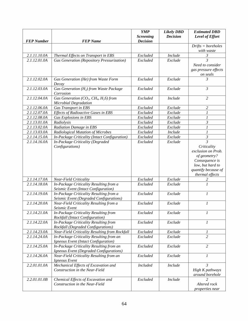
64
FEP Number FEP Name
YMP Screening Decision
Likely DBD Decision
Estimated DBD Level of Effort
Drifts = boreholes with waste
2.1.11.10.0A Thermal Effects on Transport in EBS Excluded Include 3 2.1.12.01.0A Gas Generation (Repository Pressurization) Excluded Exclude 3
Need to consider gas pressure effects
on seals 2.1.12.02.0A Gas Generation (He) from Waste Form
Decay Excluded Exclude 3
2.1.12.03.0A Gas Generation (H2) from Waste Package Corrosion
Excluded Exclude 3
2.1.12.04.0A Gas Generation (CO2, CH4, H2S) from Microbial Degradation
Excluded Include 2
2.1.12.06.0A Gas Transport in EBS Excluded Exclude 2 2.1.12.07.0A Effects of Radioactive Gases in EBS Excluded Exclude 1 2.1.12.08.0A Gas Explosions in EBS Excluded Exclude 1 2.1.13.01.0A Radiolysis Excluded Exclude 3 2.1.13.02.0A Radiation Damage in EBS Excluded Exclude 1 2.1.13.03.0A Radiological Mutation of Microbes Excluded Include 1 2.1.14.15.0A In-Package Criticality (Intact Configuration) Excluded Exclude 3 2.1.14.16.0A In-Package Criticality (Degraded
Configurations)
Excluded Exclude 3 Criticality
exclusion on Prob. of geometry?
Consequence is low, but hard to
quantify because of thermal effects
2.1.14.17.0A Near-Field Criticality Excluded Exclude 2 2.1.14.18.0A In-Package Criticality Resulting from a
Seismic Event (Intact Configuration) Excluded Exclude 1
2.1.14.19.0A In-Package Criticality Resulting from a Seismic Event (Degraded Configurations)
Excluded Exclude 1
2.1.14.20.0A Near-Field Criticality Resulting from a Seismic Event
Excluded Exclude 1
2.1.14.21.0A In-Package Criticality Resulting from Rockfall (Intact Configuration)
Excluded Exclude 1
2.1.14.22.0A In-Package Criticality Resulting from Rockfall (Degraded Configurations)
Excluded Exclude 1
2.1.14.23.0A Near-Field Criticality Resulting from Rockfall Excluded Exclude 1 2.1.14.24.0A In-Package Criticality Resulting from an
Igneous Event (Intact Configuration) Excluded Exclude 2
2.1.14.25.0A In-Package Criticality Resulting from an Igneous Event (Degraded Configurations)
Excluded Exclude 2
2.1.14.26.0A Near-Field Criticality Resulting from an Igneous Event
Excluded Exclude 1
2.2.01.01.0A Mechanical Effects of Excavation and Construction in the Near-Field
Included Include 3 High K pathways around borehole
2.2.01.01.0B Chemical Effects of Excavation and Construction in the Near-Field
Excluded Include 2 Altered rock
properties near

65
FEP Number FEP Name
YMP Screening Decision
Likely DBD Decision
Estimated DBD Level of Effort
borehole 2.2.01.02.0A Thermally-Induced Stress Changes in the
Near-Field Excluded Include 3
2.2.01.02.0B Chemical Changes in the Near-Field from Backfill
Excluded Exclude 1
2.2.01.03.0A Changes In Fluid Saturations in the Excavation Disturbed Zone
Excluded Exclude 1
2.2.01.04.0A Radionuclide Solubility in the Excavation Disturbed Zone
Excluded Include 2
2.2.01.05.0A Radionuclide Transport in the Excavation Disturbed Zone
Excluded Include 3
2.2.03.01.0A Stratigraphy Included Include 1 2.2.03.02.0A Rock Properties of Host Rock and Other
Units Included Include 1
2.2.06.01.0A Seismic Activity Changes Porosity and Permeability of Rock
Excluded Exclude 1
2.2.06.02.0A Seismic Activity Changes Porosity and Permeability of Faults
Excluded Exclude 1
2.2.06.02.0B Seismic Activity Changes Porosity and Permeability of Fractures
Excluded Exclude 1
2.2.06.03.0A Seismic Activity Alters Perched Water Zones Excluded Exclude 1 2.2.06.04.0A Effects of Subsidence Excluded Exclude 1 2.2.06.05.0A Salt Creep Excluded Exclude 1 2.2.07.01.0A Locally Saturated Flow at Bedrock/Alluvium
Contact Excluded Exclude 1
2.2.07.02.0A Unsaturated Groundwater Flow in the Geosphere
Included Exclude 1
2.2.07.03.0A Capillary Rise in the UZ Included Exclude 1 2.2.07.04.0A Focusing of Unsaturated Flow (Fingers,
Weeps) Included Exclude 1
2.2.07.05.0A Flow in the UZ from Episodic Infiltration Excluded Exclude 1 2.2.07.06.0A Episodic Or Pulse Release from Repository Excluded Exclude 1 2.2.07.06.0B Long-Term Release of Radionuclides from
The Repository Included Include 2
2.2.07.07.0A Perched Water Develops Included Exclude 1 2.2.07.08.0A Fracture Flow in the UZ Included Exclude 1 2.2.07.09.0A Matrix Imbibition in the UZ Included Exclude 1 2.2.07.10.0A Condensation Zone Forms Around Drifts Included Exclude 1 2.2.07.11.0A Resaturation of Geosphere Dry-Out Zone Included Include 1 2.2.07.12.0A Saturated Groundwater Flow in the
Geosphere Included Include 3
This is one of two release pathways (EBS transport
through seals is the other)
2.2.07.13.0A Water-Conducting Features in the SZ Included Included 3 2.2.07.14.0A Chemically-Induced Density Effects on
Groundwater Flow Excluded Exclude 1
2.2.07.15.0A Advection and Dispersion in the SZ Included Include 3 2.2.07.15.0B Advection and Dispersion in the UZ Included Exclude 1 2.2.07.16.0A Dilution of Radionuclides in Groundwater Included Include 1
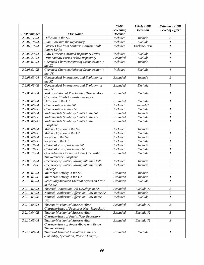
66
FEP Number FEP Name
YMP Screening Decision
Likely DBD Decision
Estimated DBD Level of Effort
2.2.07.17.0A Diffusion in the SZ Included Include 3 2.2.07.18.0A Film Flow into the Repository Included Exclude 1 2.2.07.19.0A Lateral Flow from Solitario Canyon Fault
Enters Drifts Included Exclude (NA) 1
2.2.07.20.0A Flow Diversion Around Repository Drifts Included Exclude 1 2.2.07.21.0A Drift Shadow Forms Below Repository Excluded Exclude 1 2.2.08.01.0A Chemical Characteristics of Groundwater in
the SZ Included Include 1
2.2.08.01.0B Chemical Characteristics of Groundwater in the UZ
Included Exclude 1
2.2.08.03.0A Geochemical Interactions and Evolution in the SZ
Excluded Include 2
2.2.08.03.0B Geochemical Interactions and Evolution in the UZ
Excluded Exclude 1
2.2.08.04.0A Re-Dissolution of Precipitates Directs More Corrosive Fluids to Waste Packages
Excluded Exclude 1
2.2.08.05.0A Diffusion in the UZ Excluded Exclude 1 2.2.08.06.0A Complexation in the SZ Included Include? ? 2.2.08.06.0B Complexation in the UZ Included Exclude 1 2.2.08.07.0A Radionuclide Solubility Limits in the SZ Excluded Include 2 2.2.08.07.0B Radionuclide Solubility Limits in the UZ Excluded Exclude 1 2.2.08.07.0C Radionuclide Solubility Limits in the
Biosphere Excluded Exclude 1
2.2.08.08.0A Matrix Diffusion in the SZ Included Include 3 2.2.08.08.0B Matrix Diffusion in the UZ Included Exclude 1 2.2.08.09.0A Sorption in the SZ Included Include 3 2.2.08.09.0B Sorption in the UZ Included Exclude 1 2.2.08.10.0A Colloidal Transport in the SZ Included Include 3 2.2.08.10.0B Colloidal Transport in the UZ Included Exclude 1 2.2.08.11.0A Groundwater Discharge to Surface Within
The Reference Biosphere Excluded Exclude 1
2.2.08.12.0A Chemistry of Water Flowing into the Drift Included Include 2 2.2.08.12.0B Chemistry of Water Flowing into the Waste
Package Included Include 2
2.2.09.01.0A Microbial Activity in the SZ Excluded Include 2 2.2.09.01.0B Microbial Activity in the UZ Excluded Include 1 2.2.10.01.0A Repository-Induced Thermal Effects on Flow
in the UZ Excluded Exclude 1
2.2.10.02.0A Thermal Convection Cell Develops in SZ Excluded Exclude ?? 3 2.2.10.03.0A Natural Geothermal Effects on Flow in the SZ Included Include 2 2.2.10.03.0B Natural Geothermal Effects on Flow in the
UZ Included Exclude 1
2.2.10.04.0A Thermo-Mechanical Stresses Alter Characteristics of Fractures Near Repository
Excluded Exclude ?? 3
2.2.10.04.0B Thermo-Mechanical Stresses Alter Characteristics of Faults Near Repository
Excluded Exclude ?? 3
2.2.10.05.0A Thermo-Mechanical Stresses Alter Characteristics of Rocks Above and Below The Repository
Excluded Exclude ?? 3
2.2.10.06.0A Thermo-Chemical Alteration in the UZ (Solubility, Speciation, Phase Changes,
Excluded Exclude 1
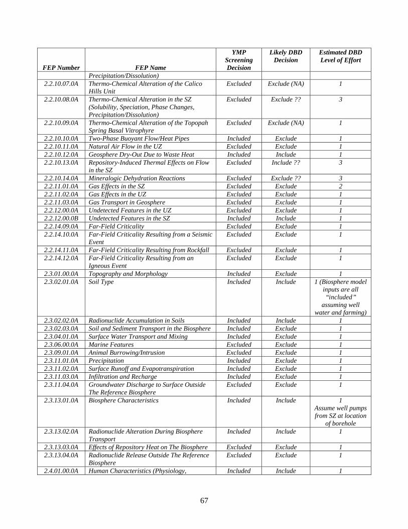
67
FEP Number FEP Name
YMP Screening Decision
Likely DBD Decision
Estimated DBD Level of Effort
Precipitation/Dissolution) 2.2.10.07.0A Thermo-Chemical Alteration of the Calico
Hills Unit Excluded Exclude (NA) 1
2.2.10.08.0A Thermo-Chemical Alteration in the SZ (Solubility, Speciation, Phase Changes, Precipitation/Dissolution)
Excluded Exclude ?? 3
2.2.10.09.0A Thermo-Chemical Alteration of the Topopah Spring Basal Vitrophyre
Excluded Exclude (NA) 1
2.2.10.10.0A Two-Phase Buoyant Flow/Heat Pipes Included Exclude 1 2.2.10.11.0A Natural Air Flow in the UZ Excluded Exclude 1 2.2.10.12.0A Geosphere Dry-Out Due to Waste Heat Included Include 1 2.2.10.13.0A Repository-Induced Thermal Effects on Flow
in the SZ Excluded Include ?? 3
2.2.10.14.0A Mineralogic Dehydration Reactions Excluded Exclude ?? 3 2.2.11.01.0A Gas Effects in the SZ Excluded Exclude 2 2.2.11.02.0A Gas Effects in the UZ Excluded Exclude 1 2.2.11.03.0A Gas Transport in Geosphere Excluded Exclude 1 2.2.12.00.0A Undetected Features in the UZ Excluded Exclude 1 2.2.12.00.0B Undetected Features in the SZ Included Include 1 2.2.14.09.0A Far-Field Criticality Excluded Exclude 1 2.2.14.10.0A Far-Field Criticality Resulting from a Seismic
Event Excluded Exclude 1
2.2.14.11.0A Far-Field Criticality Resulting from Rockfall Excluded Exclude 1 2.2.14.12.0A Far-Field Criticality Resulting from an
Igneous Event Excluded Exclude 1
2.3.01.00.0A Topography and Morphology Included Exclude 1 2.3.02.01.0A Soil Type Included Include 1 (Biosphere model
inputs are all “included”
assuming well water and farming)
2.3.02.02.0A Radionuclide Accumulation in Soils Included Include 1 2.3.02.03.0A Soil and Sediment Transport in the Biosphere Included Exclude 1 2.3.04.01.0A Surface Water Transport and Mixing Included Exclude 1 2.3.06.00.0A Marine Features Excluded Exclude 1 2.3.09.01.0A Animal Burrowing/Intrusion Excluded Exclude 1 2.3.11.01.0A Precipitation Included Exclude 1 2.3.11.02.0A Surface Runoff and Evapotranspiration Included Exclude 1 2.3.11.03.0A Infiltration and Recharge Included Exclude 1 2.3.11.04.0A Groundwater Discharge to Surface Outside
The Reference Biosphere Excluded Exclude 1
2.3.13.01.0A Biosphere Characteristics Included Include 1 Assume well pumps from SZ at location
of borehole 2.3.13.02.0A Radionuclide Alteration During Biosphere
Transport Included Include 1
2.3.13.03.0A Effects of Repository Heat on The Biosphere Excluded Exclude 1 2.3.13.04.0A Radionuclide Release Outside The Reference
Biosphere Excluded Exclude 1
2.4.01.00.0A Human Characteristics (Physiology, Included Include 1
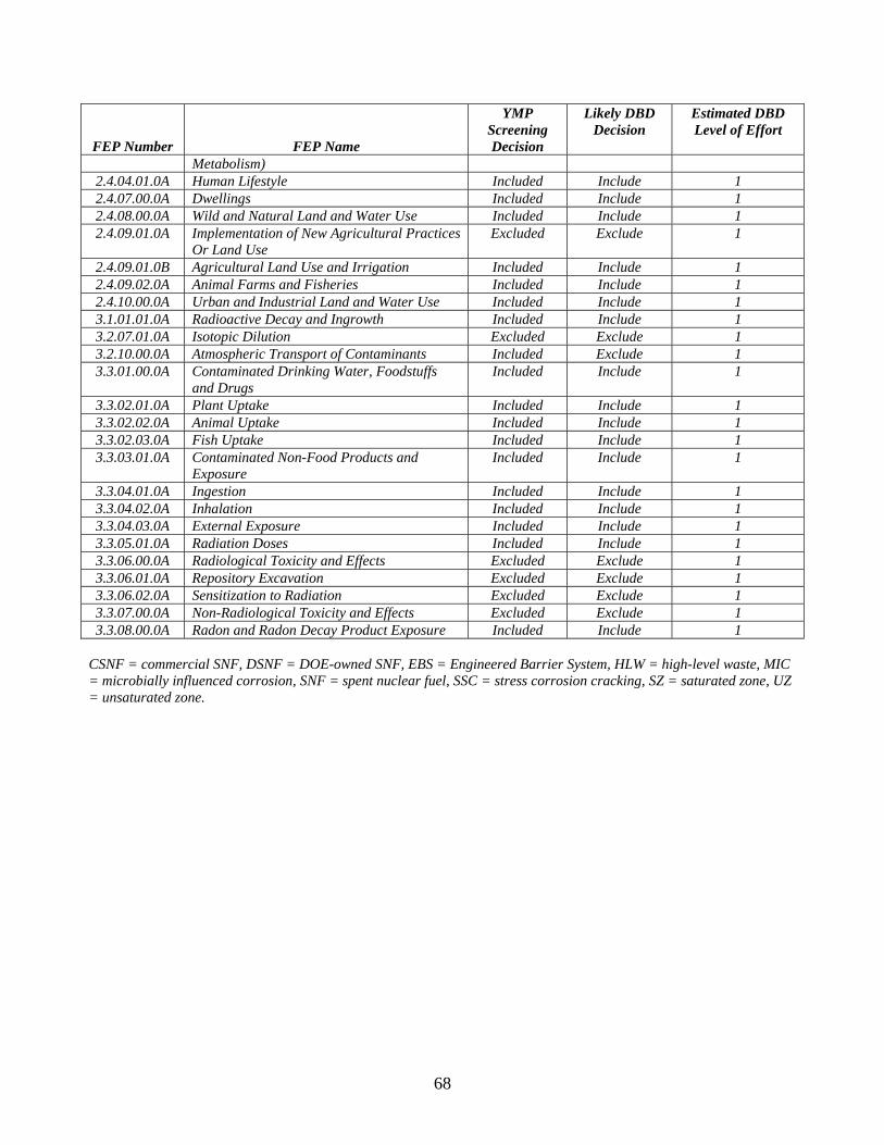
68
FEP Number FEP Name
YMP Screening Decision
Likely DBD Decision
Estimated DBD Level of Effort
Metabolism) 2.4.04.01.0A Human Lifestyle Included Include 1 2.4.07.00.0A Dwellings Included Include 1 2.4.08.00.0A Wild and Natural Land and Water Use Included Include 1 2.4.09.01.0A Implementation of New Agricultural Practices
Or Land Use Excluded Exclude 1
2.4.09.01.0B Agricultural Land Use and Irrigation Included Include 1 2.4.09.02.0A Animal Farms and Fisheries Included Include 1 2.4.10.00.0A Urban and Industrial Land and Water Use Included Include 1 3.1.01.01.0A Radioactive Decay and Ingrowth Included Include 1 3.2.07.01.0A Isotopic Dilution Excluded Exclude 1 3.2.10.00.0A Atmospheric Transport of Contaminants Included Exclude 1 3.3.01.00.0A Contaminated Drinking Water, Foodstuffs
and Drugs Included Include 1
3.3.02.01.0A Plant Uptake Included Include 1 3.3.02.02.0A Animal Uptake Included Include 1 3.3.02.03.0A Fish Uptake Included Include 1 3.3.03.01.0A Contaminated Non-Food Products and
Exposure Included Include 1
3.3.04.01.0A Ingestion Included Include 1 3.3.04.02.0A Inhalation Included Include 1 3.3.04.03.0A External Exposure Included Include 1 3.3.05.01.0A Radiation Doses Included Include 1 3.3.06.00.0A Radiological Toxicity and Effects Excluded Exclude 1 3.3.06.01.0A Repository Excavation Excluded Exclude 1 3.3.06.02.0A Sensitization to Radiation Excluded Exclude 1 3.3.07.00.0A Non-Radiological Toxicity and Effects Excluded Exclude 1 3.3.08.00.0A Radon and Radon Decay Product Exposure Included Include 1
CSNF = commercial SNF, DSNF = DOE-owned SNF, EBS = Engineered Barrier System, HLW = high-level waste, MIC = microbially influenced corrosion, SNF = spent nuclear fuel, SSC = stress corrosion cracking, SZ = saturated zone, UZ = unsaturated zone.

69
Table B-2. High Priority Borehole FEPs – Excluded FEPs That Need New Technical Work and Included FEPs That Require Significant Modeling or Possible Model Changes.
FEP Number FEP Name Likely DBD
Decision Estimated DB
Level of Effort 0.1.09.00.0A Regulatory Requirements and Exclusions Include 3
Regulations and laws will need to be
revised 1.1.02.00.0A Chemical Effects of Excavation and
Construction in EBS Exclude 2
1.1.02.00.0B Mechanical Effects of Excavation and Construction in EBS
Include 2
1.1.02.03.0A Undesirable Materials Left Exclude (NA) 2 1.1.03.01.0A Error in Waste Emplacement Exclude 3
Need to consider the emplacement
that gets stuck halfway down. Also need to
consider canisters that are crushed by overlying canisters
1.1.04.01.0A Incomplete Closure Exclude 2 1.1.13.00.0A Retrievability Exclude
(policy) 2
1.2.02.01.0A Fractures Include 2 1.2.02.02.0A Faults Include 2 1.2.02.03.0A Fault Displacement Damages EBS
Components Include? 2
Note—if no credit is taken for WP and WF components, all
EBS FEPs are simplified to the
consideration of the borehole seals
1.2.03.02.0A Seismic Ground Motion Damages EBS Components
Exclude 2
1.2.04.02.0A Igneous Activity Changes Rock Properties Exclude 2 Need to evaluate
potential for igneous activity at each site (should
generically be low), also need to determine if
repository heat can contribute to rock
melting 1.2.04.03.0A Igneous Intrusion Into Repository Exclude 2 1.2.04.04.0A Igneous Intrusion Interacts With EBS
Components Exclude 2
1.2.04.04.0B Chemical Effects of Magma and Magmatic Volatiles
Exclude 2 Volatiles may
impact transport

70
FEP Number FEP Name Likely DBD
Decision Estimated DB
Level of Effort 1.2.04.06.0A Eruptive Conduit to Surface Intersects
Repository Exclude 2
1.2.05.00.0A Metamorphism Exclude 2 Repository heat
may create metamorphic
conditions 1.2.06.00.0A Hydrothermal Activity Exclude 3
Repository heat may creat local hydrothermal
activity 1.2.08.00.0A Diagenesis Exclude 2 1.2.09.01.0A Diapirism Exclude 2
Need to demonstrate that
repository heat will not generate local
diapirism 1.2.10.02.0A Hydrologic Response to Igneous Activity Exclude 2 1.3.07.02.0B Water Table Rise Affects UZ Exclude 1
All UZ FEPs are simplified
1.4.02.02.0A Inadvertent Human Intrusion Exclude 1 (requires regulatory change)
2.1.02.02.0A CSNF Degradation (Alteration, Dissolution, and Radionuclide Release)
Exclude 1 Assume no credit for CSNF waste
form 2.1.02.03.0A HLW Glass Degradation (Alteration,
Dissolution, and Radionuclide Release) Exclude 1
Assume no credit for HLW waste
form 2.1.05.01.0A Flow Through Seals (Access Ramps and
Ventilation Shafts) Include 3
2.1.05.02.0A Radionuclide Transport Through Seals Include 3 2.1.05.03.0A Degradation of Seals Include 3 2.1.06.01.0A Chemical Effects of Rock Reinforcement and
Cementitious Materials in EBS Include
(Seals are EBS, so one
entire release pathway to RMEI is in
EBS)
3
2.1.06.02.0A Mechanical Effects of Rock Reinforcement Materials in EBS
Include 3 What happens to borehole seal as casing degrades?
2.1.06.07.0A Chemical Effects at EBS Component Interfaces
Include? 2
2.1.06.07.0B Mechanical Effects at EBS Component Interfaces
Exclude? 3
2.1.07.02.0A Drift Collapse Exclude 1
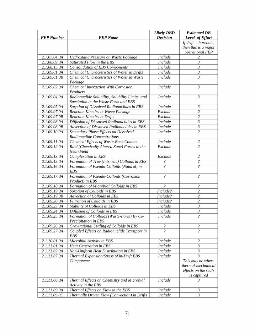
71
FEP Number FEP Name Likely DBD
Decision Estimated DB
Level of Effort If drift = borehole, then this is a major operational FEP
2.1.07.04.0A Hydrostatic Pressure on Waste Package Include 2 2.1.08.09.0A Saturated Flow in the EBS Include 3 2.1.08.15.0A Consolidation of EBS Components Include 3 2.1.09.01.0A Chemical Characteristics of Water in Drifts Include 3 2.1.09.01.0B Chemical Characteristics of Water in Waste
Package Include 3
2.1.09.02.0A Chemical Interaction With Corrosion Products
Include 3
2.1.09.04.0A Radionuclide Solubility, Solubility Limits, and Speciation in the Waste Form and EBS
Include 3
2.1.09.05.0A Sorption of Dissolved Radionuclides in EBS Include 3 2.1.09.07.0A Reaction Kinetics in Waste Package Exclude 2 2.1.09.07.0B Reaction Kinetics in Drifts Exclude 2 2.1.09.08.0A Diffusion of Dissolved Radionuclides in EBS Include 3 2.1.09.08.0B Advection of Dissolved Radionuclides in EBS Include 3 2.1.09.10.0A Secondary Phase Effects on Dissolved
Radionuclide Concentrations Include 2
2.1.09.11.0A Chemical Effects of Waste-Rock Contact Include 2 2.1.09.12.0A Rind (Chemically Altered Zone) Forms in the
Near-Field Exclude 2
2.1.09.13.0A Complexation in EBS Exclude 2 2.1.09.15.0A Formation of True (Intrinsic) Colloids in EBS ? ? 2.1.09.16.0A Formation of Pseudo-Colloids (Natural) in
EBS ? ?
2.1.09.17.0A Formation of Pseudo-Colloids (Corrosion Product) in EBS
? ?
2.1.09.18.0A Formation of Microbial Colloids in EBS ? ? 2.1.09.19.0A Sorption of Colloids in EBS Include? 2 2.1.09.19.0B Advection of Colloids in EBS Include? 2 2.1.09.20.0A Filtration of Colloids in EBS Include? 2 2.1.09.23.0A Stability of Colloids in EBS Include 3 2.1.09.24.0A Diffusion of Colloids in EBS Include 3 2.1.09.25.0A Formation of Colloids (Waste-Form) By Co-
Precipitation in EBS Include ?
2.1.09.26.0A Gravitational Settling of Colloids in EBS ? ? 2.1.09.27.0A Coupled Effects on Radionuclide Transport in
EBS ? ?
2.1.10.01.0A Microbial Activity in EBS Include 2 2.1.11.01.0A Heat Generation in EBS Include 3 2.1.11.02.0A Non-Uniform Heat Distribution in EBS Include 3 2.1.11.07.0A Thermal Expansion/Stress of in-Drift EBS
Components Include 3
This may be where thermal-mechanical effects on the seals
is captured 2.1.11.08.0A Thermal Effects on Chemistry and Microbial
Activity in the EBS Include 3
2.1.11.09.0A Thermal Effects on Flow in the EBS Include 3 2.1.11.09.0C Thermally Driven Flow (Convection) in Drifts Include 3
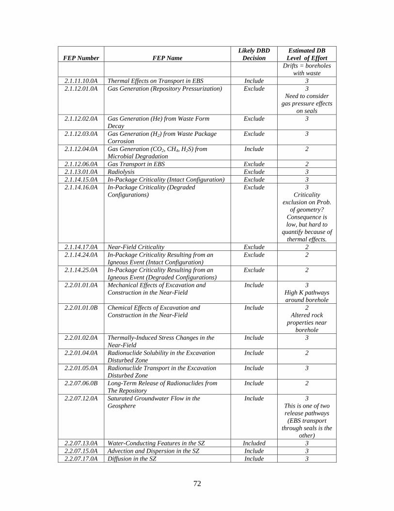
72
FEP Number FEP Name Likely DBD
Decision Estimated DB
Level of Effort Drifts = boreholes
with waste 2.1.11.10.0A Thermal Effects on Transport in EBS Include 3 2.1.12.01.0A Gas Generation (Repository Pressurization) Exclude 3
Need to consider gas pressure effects
on seals 2.1.12.02.0A Gas Generation (He) from Waste Form
Decay Exclude 3
2.1.12.03.0A Gas Generation (H2) from Waste Package Corrosion
Exclude 3
2.1.12.04.0A Gas Generation (CO2, CH4, H2S) from Microbial Degradation
Include 2
2.1.12.06.0A Gas Transport in EBS Exclude 2 2.1.13.01.0A Radiolysis Exclude 3 2.1.14.15.0A In-Package Criticality (Intact Configuration) Exclude 3 2.1.14.16.0A In-Package Criticality (Degraded
Configurations) Exclude 3
Criticality exclusion on Prob.
of geometry? Consequence is low, but hard to
quantify because of thermal effects.
2.1.14.17.0A Near-Field Criticality Exclude 2 2.1.14.24.0A In-Package Criticality Resulting from an
Igneous Event (Intact Configuration) Exclude 2
2.1.14.25.0A In-Package Criticality Resulting from an Igneous Event (Degraded Configurations)
Exclude 2
2.2.01.01.0A Mechanical Effects of Excavation and Construction in the Near-Field
Include 3 High K pathways around borehole
2.2.01.01.0B Chemical Effects of Excavation and Construction in the Near-Field
Include 2 Altered rock
properties near borehole
2.2.01.02.0A Thermally-Induced Stress Changes in the Near-Field
Include 3
2.2.01.04.0A Radionuclide Solubility in the Excavation Disturbed Zone
Include 2
2.2.01.05.0A Radionuclide Transport in the Excavation Disturbed Zone
Include 3
2.2.07.06.0B Long-Term Release of Radionuclides from The Repository
Include 2
2.2.07.12.0A Saturated Groundwater Flow in the Geosphere
Include 3 This is one of two release pathways (EBS transport
through seals is the other)
2.2.07.13.0A Water-Conducting Features in the SZ Included 3 2.2.07.15.0A Advection and Dispersion in the SZ Include 3 2.2.07.17.0A Diffusion in the SZ Include 3
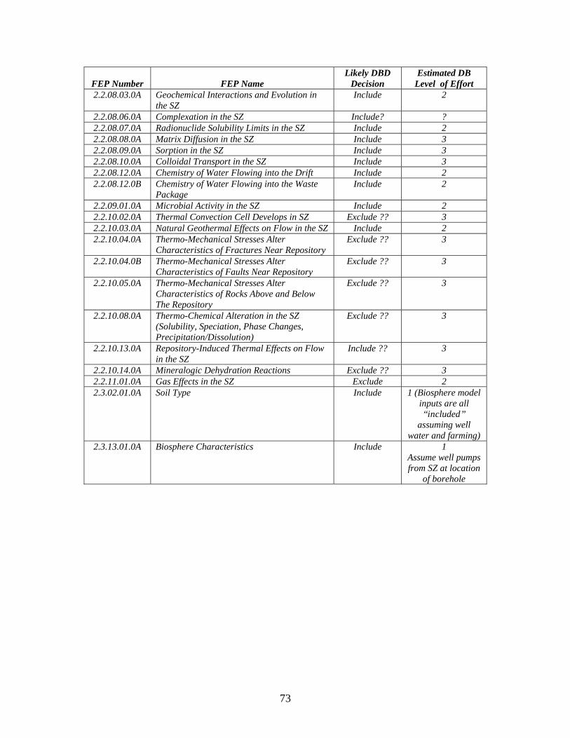
73
FEP Number FEP Name Likely DBD
Decision Estimated DB
Level of Effort 2.2.08.03.0A Geochemical Interactions and Evolution in
the SZ Include 2
2.2.08.06.0A Complexation in the SZ Include? ? 2.2.08.07.0A Radionuclide Solubility Limits in the SZ Include 2 2.2.08.08.0A Matrix Diffusion in the SZ Include 3 2.2.08.09.0A Sorption in the SZ Include 3 2.2.08.10.0A Colloidal Transport in the SZ Include 3 2.2.08.12.0A Chemistry of Water Flowing into the Drift Include 2 2.2.08.12.0B Chemistry of Water Flowing into the Waste
Package Include 2
2.2.09.01.0A Microbial Activity in the SZ Include 2 2.2.10.02.0A Thermal Convection Cell Develops in SZ Exclude ?? 3 2.2.10.03.0A Natural Geothermal Effects on Flow in the SZ Include 2 2.2.10.04.0A Thermo-Mechanical Stresses Alter
Characteristics of Fractures Near Repository Exclude ?? 3
2.2.10.04.0B Thermo-Mechanical Stresses Alter Characteristics of Faults Near Repository
Exclude ?? 3
2.2.10.05.0A Thermo-Mechanical Stresses Alter Characteristics of Rocks Above and Below The Repository
Exclude ?? 3
2.2.10.08.0A Thermo-Chemical Alteration in the SZ (Solubility, Speciation, Phase Changes, Precipitation/Dissolution)
Exclude ?? 3
2.2.10.13.0A Repository-Induced Thermal Effects on Flow in the SZ
Include ?? 3
2.2.10.14.0A Mineralogic Dehydration Reactions Exclude ?? 3 2.2.11.01.0A Gas Effects in the SZ Exclude 2 2.3.02.01.0A Soil Type Include 1 (Biosphere model
inputs are all “included”
assuming well water and farming)
2.3.13.01.0A Biosphere Characteristics Include 1 Assume well pumps from SZ at location
of borehole
74
DISTRIBUTION 1 Dr. Michael J. Driscoll Department of Nuclear Science and Engineering Massachusetts Institute of Technology 77 Massachusetts Ave.
Cambridge, MA 02139 1 Dr. Richard K. Lester Department of Nuclear Science and Engineering Massachusetts Institute of Technology 77 Massachusetts Ave.
Cambridge, MA 02139 1 MS0701 Sidney M. Gutierrez 6700 1 MS0724 Les E. Shephard 6000 1 MS0735 John A. Merson 6310 1 MS0736 John E. Kelly 6770 1 MS0736 Marianne C. Walck 6760 5 MS0754 Patrick V. Brady 6310 10 MS0771 Stanley A. Orrell 6800 5 MS0776 Geoffrey A. Freeze 6784 5 MS0776 Robert P. Rechard 6782 1 MS0776 Robert J. MacKinnon 6782 1 MS0776 Stephanie P. Kuzio 6787 5 MS0778 Bill W. Arnold 6782 5 MS0778 Peter N. Swift 6780 5 MS1033 Stephen J. Bauer 6315 5 MS1033 Joshua S. Stein 6335 5 MS1395 Joseph F. Kanney 6711 1 MS1395 Courtney G. Herrick 6711 1 MS1395 David S. Kessel 6710 1 MS1395 Moo Y. Lee 6711 1 MS1399 Clifford L. Howard 6785 1 MS1399 Jerry McNeish 6784 1 MS1399 Evaristo J. Bonano 6780 1 MS1399 Jack B. Tillman 6780 1 MS9409 Scott C. James 8365 2 MS9018 Central Technical Files 8944 1 MS 0899 Technical Library 9536 (electronic copy)