DECwriter 500i DECcolorwriter 520ic
100
DECwriter 500i DECcolorwriter 520ic (LJ500 and LJ520) Service Manual EK-LJ50E-SV.A01
Transcript of DECwriter 500i DECcolorwriter 520ic

DECwriter 500i
DECcolorwriter 520ic(LJ500 and LJ520)
Service Manual
EK-LJ50E-SV.A01

First Edition - July 1994
The information in this document is subject to change without notice and shouldnot be construed as a commitment by Digital Equipment Corporation. DigitalEquipment Corporation assumes no responsibility for any errors that may appearin this document.
Copyright Digital Equipment Corporation 1994
All rights reserved.Printed in Europe
The following are trademarks of Digital Equipment Corporation:
DEC, DECcolorwriter 520ic, DECwriter 500i and the Digital logo:
TRADEMARKS:
CENTRONICS is a registered trademark of Centronics Data ComputerCorporation EPSON and LQ 850 are registered trademarks of Epson SeikoCorporationHP, DeskJet and PCL III + are registered trademarks of Hewlett-PackardCompanyIBM and Proprinter X24 are registered trademarks of International BusinessMachines CorporationMS-DOS and MS-WINDOWS are registered trademarks of MicrosoftCorporation.UNIX is a registered trademark of UNIX System Laboratories, Inc. in the UnitedStates of America and other countries.

i
PREFACEThis service manual provides technical, mechanical and electronic information forproduct support.
Refer to this manual when a fault has not been corrected using therecommendations described in the Installation and User Guide included with theprinter.
SummaryThis manual is divided into 9 chapters and 1 appendix which contains the list ofrecommended spares (FRU). The chapters are organized to develop anautonomous and gradual approach to printer problems.
Some paragraphs are marked on a dark background and advise the use ofparticularly important situations or procedures. If these observations are notheeded, the printer could malfunction.
Associated DocumentationEK-LJ50*-UG DECwriter 500i & DECcolorwriter 520i -
Installation and User Guide
EK-LJ50*-RF Read-Me-First - DECwriter 500iEK-LJ52E-RF Read-Me-First - DECcolorwriter 520i
(English only)
The * in the above two part numbers corresponds to the language identifier for theappropriate language, e.g. F- French, G- German and so on.
Languages supported are English (UK and USA), French, German, Italian andSpanish

ii
FEDERAL COMMUNICATIONS COMMISSIONRADIO FREQUENCY INTERFERENCE STATEMENT
INFORMATION TO THE USER
NOTE: This equipment has been tested and found to comply with the limits for aClass B digital device pursuant to Part 15 of the FCC Rules. These limits aredesigned to provide reasonable protection against harmful interference in aresidential installation. This equipment generates, uses and can radiate radiofrequency energy and, if not installed and used in accordance with theinstructions, may cause harmful interference to radio communications. However,there is no guarantee that interference will not occur in a particular installation. Ifthis equipment does cause harmful interference to radio or television reception,which can be determined by turning the equipment off and on, the user isencouraged to try to correct the interference by one or more of the followingmeasures:
• Reorient or relocate the receiving antenna• Increase the separation between the equipment and receiver• Connect the equipment to an outlet of a circuit different from that to which
the receiver is connected• Consult the dealer or an experienced radio/TV technician for assistance.
Changes or modifications not expressly approved by the party responsible forcompliance could void the user’s authority to operate the equipment. Connectingof peripherals requires the use of grounded shielded cables.
EMI Requirements for Canadian Market
This digital apparatus does not exceed the class B limits for radio noise emissionsfrom digital apparatuses as set forth in the radio interference regulations of theCanadian Department of Communications.
Spécifications EMI pour le Marché Canadien
Le présent appareil numérique n’emet pas de bruits radioélectriques dépassant leslimites applicables aux appareils numériques de classe B prescrites dans lereglement sur le brouillage radioélectrique edicté par le Ministere desCommunications du Canada.
This equipment conforms to the specifications of EEC directive 87/308 on theprevention and elimination of radio-frequency disturbances.
NOTICE Digital Equipment Corp. reserves the right to modify the equipment described in thismanual at any time and without notice.

iii
ContentsPREFACE.................................................................................................... iSummary ...................................................................................................... iAssociated Documentation............................................................................ iFEDERAL COMMUNICATIONS COMMISSION RADIO FREQUENCYINTERFERENCE STATEMENT ................................................................. iiContents ....................................................................................................... iii
1. GENERAL
1.1 INTRODUCTION.................................................................................. 1-11.2 TECHNICAL CHARACTERISTICS..................................................... 1-21.3 FIRMWARE AND CHARACTER GENERATORS.............................. 1-5Basic emulations........................................................................................... 1-5
Optional emulations:.............................................................................. 1-5Character generator:............................................................................... 1-5Character set: ......................................................................................... 1-6Basic emulation optional fonts:.............................................................. 1-8
1- "Prestige Elite" card (256 Kbytes)............................................ 1-82- "Times Nordic" card (256 Kbytes) ............................................ 1-93- "Nordic" card (256 Kbytes)...................................................... 1-9
1.4 Product OPTIONS................................................................................. 1-9
2. FUNCTIONAL DESCRIPTION
2.1 GENERAL BLOCK DIAGRAM........................................................... 2-12.2 Printer Components and Internals .......................................................... 2-22.3 BLACK INK-JET HEAD FUNCTIONING............................................ 2-5
Ink jet head description:......................................................................... 2-5How an Ink-jet works............................................................................. 2-6The nozzles:........................................................................................... 2-8
2.4 COLOR INK-JET HEAD FUNCTIONING.............................................2-10Ink jet head description:.........................................................................2-10Ink jet printing functioning principle:.....................................................2-12The nozzles:...........................................................................................2-12Resistor enabling circuit specifications: .................................................2-13
2.5 OPERATING CONTROLS....................................................................2-14Operator Panel .......................................................................................2-14Key functions.........................................................................................2-15
2.6 COLOR SELECTION LEVER ...............................................................2-18

iv
3. INSTALLATION
3.1 GENERAL INSTRUCTIONS................................................................. 3-1Mains power supply:.............................................................................. 3-1Environmental conditions: ..................................................................... 3-1Product positioning: ............................................................................... 3-1
3.2 UNPACKING......................................................................................... 3-2Packing check:....................................................................................... 3-2
3.3 CONNECTION TO THE MAINS........................................................... 3-33.4 INSTALLING THE PRINT HEAD......................................................... 3-33.5 INSERTING AN OPTIONAL MEMORY/FONT CARD........................ 3-53.6 PAPER FEED......................................................................................... 3-6
ASF sheet feed:...................................................................................... 3-6Manual insertion: ................................................................................... 3-8
3.7 SPROCKET INSTALLATION...............................................................3-10Paper loading by sprocket: .....................................................................3-10
3.8 2nd PAPER TRAY (ASF2) INSTALLATION........................................3-11Paper insertion from second ASF drawer: ..............................................3-11
3.10 SERIAL INTERFACE INSTALLATION.............................................3-123.11 PRINT TEST ........................................................................................3-133.12 SYSTEM CONNECTION.....................................................................3-13
Centronics parallel interface ..................................................................3-133.13 SWITCHING OFF THE PRINTER.......................................................3-153.14. INSTALLATION SET UP..................................................................3-15
DEFAULT parameters ...........................................................................3-16PROGRAMMABLE PARAMETERS....................................................3-17SYSTEM PARAMETER SET-UP.........................................................3-22
4. USER MAINTENANCE
4.1 NOZZLE CLEANING AND INK RESET (“PRIME”)......................... 4-1Nozzle cleaning: .................................................................................... 4-1Ink reset ( ”PRIME” ) Black head only.................................................. 4-2Black Ink jet head cleaning and maintenance:........................................ 4-3Color Ink jet head cleaning and maintenance: ........................................ 4-4

v
5. DIAGNOSTICS AND TESTS
5.1 AUTODIAGNOSTICS AT POWER-ON................................................ 5-15.2 PRINT TEST WITH BLACK PRINT HEAD.......................................... 5-15.3 PRINT TEST WITH COLOR PRINT HEAD.......................................... 5-35.4 ”DATA SCOPE” PRINTOUT (HEX DUMP)....................................... 5-4
Enabling the Data Scope printout:.......................................................... 5-4Disabling the Data Scope printout:........................................................ 5-4
5.5 DIAGNOSIS GUIDELINES.................................................................. 5-5
6. FAULT CONDITIONS AND MEANING
OPERATIONAL STATUS........................................................................... 6-1Fault Conditions and Indications............................................................ 6-2Normal Conditions and Indications ........................................................ 6-3
7 MECHANICAL ADJUSTMENTS
7.1 PRINT HEAD AND THE WRITING SURFACE GAP.......................... 7-1Procedure:.............................................................................................. 7-1
7.2 ADJUSTING THE TENSION OF THE PAPER FEED MOTOR BELT.. 7-2Procedure:.............................................................................................. 7-2
7.3 BI-DIRECTIONAL PRINT ALIGNMENT ADJUSTMENT................... 7-3
8. ELECTRICAL INTERCONNECTIONS
8.1 MAIN BOARD MAIN COMPONENTS................................................. 8-18.2 POWER SUPPLY BOARD..................................................................... 8-28.3 POWER SUPPLY CIRCUIT ON MAIN BOARD................................... 8-38.4 CONNECTOR SIGNALS....................................................................... 8-4

vi
9. PARTS REPLACEMENT
9.1 WARNING NOTES................................................................................ 9-19.2 REPLACING THE INK CARTRIDGE:.................................................. 9-29.3 DISASSEMBLING/ RE-ASSEMBLING THE PRINT HEAD:.............. 9-39.4 DISASSEMBLING / RE-ASSEMBLING THE CASING........................ 9-49.5 DISASSEMBLING / RE-ASSEMBLING THE MAIN BOARD:............ 9-69.6 DISASSEMBLING/ RE-ASSEMBLING THE OPERATOR PANEL:.... 9-89.7 DISASSEMBLING / RE-ASSEMBLING THE POWER SUPPLY BOARD: 9-99.8 DISASSEMBLING / RE-ASSEMBLING THE PAPER FEED MOTOR. 9-119.9 DISASSEMBLING / RE-ASSEMBLING THE CARRIAGE MOTOR....9-129.10 DISASSEMBLING / RE-ASSEMBLING THE BLACK/COLOR SELECTIONAND SHEET PRESENCE PHOTOSENSORS..............................................9-139.11 DISASSEMBLING / RE-ASSEMBLING THE LINEAR ENCODER... 9-149.12 DISASSEMBLING / RE-ASSEMBLING THE PRINT CARRIAGE.....9-159.13 DISASSEMBLING / RE-ASSEMBLING THE PAPER OUTFEED GROUP 9-16
A. SPARE PARTS and OPTIONS List

General 1-1
1. GENERAL
1.1 INTRODUCTIONThe LJ500 and LJ520 are "bubble ink jet" printers that combine excellentquality printing with a fast writing speed, a low noise level and considerableversatility in the paper handling. With these qualities they can compete with manyLaser Printers.
This service manual is intended for the DECwriter 500i monochrome inkjetprinter with color option, and the DECcolorwriter 520ic color inkjet printerotherwise known as the LJ500 and LJ520. The only difference is that the colormodel is shipped with the color kit, and the monochrome model can be upgradedwith the color kit, which has to be ordered separately. In all other respects the twoprinters are identical and therefore all instructions and operations described in thismanual are applicable to both printer models, unless reference is made to aspecific model.
This non-impact printer is designed and constructed to guarantee reliability and togive constant quality of both text and high resolution graphics. It uses “drop ondemand” thermal ink jet technology with a monochrome (black) or colourdisposable print head, associated with very low power consumption (25W - lessthan a standard light bulb). It produces a laser-like print density of up to 300 x300 dots per inch (dpi) with minimal operating disturbance. The monochromeprint head has a rechargeable system and its ink is water- resistant.
This printer can be connected to personal computers with a standard parallel oroptional serial interface. Compatible with MS-Windows and many other softwareapplications commonly used with this class of printer, it can be used in mostworking environments. The resident firmware emulates the HP DeskJet 500Cprinter (extended PCL-III commands).

General 1-2
1.2 TECHNICAL CHARACTERISTICSPrinting Technique Non-impact, bubble ink jet
Print Head Disposable Black or Color
Black Vertical resolution: 300 dpiRepetition frequency: 5000 HzNozzles: 50 (in 4 groups of 12 or 13)Vertical construction: 2 cols of 25 nozzlesWater-resistant inkInk cartridge life: 90,000,000 dots(400,000 characters,, average or 400 pages)Replaceable ink cartridgesNo. cartridges per print head: up to 10(depending on usage: work load and storage)
Color Vertical resolution: 300 dpiRepetition frequency: 3000 HzNozzles: 51 (in 3 vertical groups: yellow, magenta, cyan)Vertical construction: 2 cols, one of 25 and one of 26 nozzlesPrint head life: 200 pages at 8% coverage
Print Matrix, 300 x 300 dpi
Print Definition
(Vertical x Horizontal) 1/300 in x 1/100 in for Draft1/300 in x 1/150 in for NLQ1/300 in x 1/300 in for LQ(rows shifted by 1/600 in.)
Print Density 75, 100, 150, 300 dpi
Print Pitch 10, 12, 16.67 cpi; PSEach basic fixed pitch value can be condensed to half and expanded to double its value(e.g.: 10cpi: 5 cpi / 20cpi)
Print Orientation Portrait and Landscape
Print Line Length (A4 paper size),Portrait orientation: - 80 characters with 10 cpi pitch
- 96 characters with 12 cpi- 132 characters with 16.67 cpi pitch

General 1-3
Landscape orientation: - 112 characters with 10 cpi pitch- 134 characters with 12 cpi- 186 characters with 16.67 cpi
Printing Speed DOS and similar environments:400 cps in Draft280 cps in NLQ160 cps in LQ
Windows and similar environments:DRAFT : up to 5 ppm (pages per minute)NLQ : up to 4 ppmLetter Quality : up to 3 ppm(these values may vary depending on the softwareapplication and/or the type of computer used)
Work Load should not exceed 350 pages per day nor 1000 pages per month, including 160 color pages
Printer Life 5 years
Print Path Bi-directional
Graphic Printing Bit Image Mode - density: 300 x 300 dpi
Ink Save Mode 10% ink saving in graphics mode
Linespacing Elementary value: 1/300 inResident value: 1/6 in (4.23 mm)
Printer Emulation Resident : PCL III +Optional : IBM -X24/EPSON LQ 850(available on Emulation card)
Paper Handling -Automatic: ASF1 (tray capacity:120x80g/m2 shts.)
Manual: including thick documents, film, envelopes (weight up to 135 g/m2) (see Chap. 3 User Guide for paper characteristics)Optional: ASF2; tractor (for fan-fold stationery)
Interface Resident: parallel (Centronics)Optional: serial (EIA RS 232C)
RAM 128K bytes
Operating Environment Temperature: 15 to 35oCRelative Humidity: 15% - 85%

General 1-4
Noise Emittance Less than 50 dBA in LQ mode
Electrical Characteristics Voltage: -110 - 120 V; +/- 10% -120 - 240 V; + 6% / - 10% Frequency: 50 or 60 Hz Power absorbed: < 25 W
Certification
For mains voltage 115 V (USA and Canada):,
Electromagnetic Compatibility FCC Class B “Certified”
Safety Regulations, USA: UL 1950/478 Canada: CSA C22.2
For mains voltage 220 - 240 V,
Electromagnetic CompatibilityEN 55022 Class B CEE 87/308VDE 0871 level B (DBP Verf.243/1991)
Safety RegulationsEN 60950 + Nordic DeviationsGermany: GS (EN 60950/9.88 eZH/618)
Physical Characteristics, Basic printer ready for use
Height - 6.81 in (173 mm)Width - 15.15 in (385 mm)Depth - 18.34 in (466 mm)Weight, - 11 lbs (5 kg)

General 1-5
1.3 FIRMWARE AND CHARACTER GENERATORS
Basic emulationsThe basic firmware, contained on 1 Mbyte ROM assembled on the BA X100board, emulates the HP Deskjet 500 and HP Deskjet 500C printers, with thecorresponding character generators.
The machine automatically makes the selection between the two emulationsaccording to the type of cartridge installed (black ink cartridge: HP Deskjet 500;color inks cartridge: HP Deskjet 500C).
Optional emulations:The available optional emulations are EPSON LQ 850 and IBM Proprinter 4207.Each emulation includes the relevant set of characters and both are contained on aspecific card.
The optional emulations cannot handle optional fonts on the memory card. Toenlarge the LQ 850 and 4207 emulation graphic fonts, the memory extensionmemory card must be inserted to handle the DLL functions (Down LineLoading).
Character generator:The task of the character generator is to assign a specific printable character toeach code included in the graphic set.
The first 128 codes in the ISO table (0-127)are the standard USA ASCIIcharacter set. This group does not include national variations or semigraphicsymbols.
The assignment of the codes included in the second ISO set table (128-255)varies from country to country and from product to product.
_______________________ Note _____________________________
For full and up-to-date details of the character sets and commandcodes, please refer to Appendix D of the User Guide

General 1-6
Character set:The character sets in the machine and available for all resident or optional fontsare the following:
CP 437 International; ROMAN 8;PC 8 Denmark/Norway; PC-850 Multilanguage/Latin 1;ECMA 94 LATIN 1 ISO 8859/1; ISO Nb 4 United Kingdom;ISO Nb 21 Germany EPSON 02; ISO Nb 69 France;ISO Nb 15 ITALY; ISO Nb 60 Norway 1;ISO Nb 61 Norway 2; ISO Nb 11 Sweden: Names EPSON05; ISO Nb 10 Sweden; ISO Nb 17 Spain;ISO Nb 6 USA (ASCII) EPSON 00; ISO Nb 2 IRV;ISO Nb 16 Portugal; ISO Nb 14 JIS ASCII;LEGAL; CP 860 Portugal;Denmark OPE 1 ; UNIX International;Denmark OPE 2; Spain2; CP 863 French/Canadian.
Further character sets in the machine and available for the ROM resident fonts(Courier, Letter Gothic and Times Nordic) are:
PC WIN1 (ANSI WINDOWS 3.1); CP 852 Latin 2;ISO 8859/2 Latin 2; PC WIN2 (East Europe. Win 3.1);CP 857 Turkish (Latin 5); ISO 8859/9 Latin 5;PC WIN3 Turkish Win 3.1 (Latin 5); CP 866 Cyrillic;CP 855 Cyrillic; ISO 8859/5 Cyrillic;PC WIN4 (Cyrillic Windows 3.1); CP 210 Greek;CP 851 Greek; ISO 8859 Greek;PC WIN5 (Greek Windows 3.1); CP 862 Hebrew;ISO 8859/8 Hebrew; PC Slovenia;PC Kamenicky.
Resident fonts:
The character fonts in the machine firmware are divided according to therequired page format: vertical or horizontal.
The list of the available fonts is shown in the tables that follow, that also indicatethe possible character heights (in print dots) and spacing (in characters per inch).

General 1-7
Fonts for vertical page format
Style Height Pitch
Courier 6 / 12 5 / 10 / 20
Courier italic 6 / 12 5 / 10 / 20
Courier 6 / 12 8,33 / 16,67 / 33,34
Letter Gothic 6 / 12 5 / 10 / 20
Letter Gothic 6 / 12 6 / 12 / 24
Letter Gothic italic 6 / 12 6 / 12 / 24
Letter Gothic 4,75 / 9,5 8,33 / 16,67 / 33,34
TMS Nordic 6 / 12 Proportional
TMS Nordic italic 6 / 12 Proportional
BF Times 7 / 14 Proportional
BF Times italic 7 / 14 Proportional
BF Times 6 / 12 Proportional
BF Times italic 6 / 12 Proportional
BF Times 5 / 10 Proportional
BF Times italic 5 / 10 Proportional
BF Times 4 / 8 Proportional
BF Times italic 4 / 8 Proportional
Line 7 / 14 Proportional
Line italic 6 / 12 Proportional
Line 6 / 12 Proportional
Line 5 / 10 Proportional
Line italic 5 / 10 Proportional
Line 4 / 8 Proportional

General 1-8
Fonts for horizontal page format
Style Height Pitch
Courier 6 / 12 / 24 10 / 20
Courier italic 6 / 12 / 24 10 / 20
Courier 6 / 12 / 24 16,67 / 33,34
Letter Gothic 6 / 12 / 24 12 / 24
Letter Gothic 4,75 / 9,5 / 19 16,67 / 33,34
Basic emulation optional fonts:An ISO code character set that is the same as the basic character generator butwith a different style. These fonts are on optional cards, and the contents of thecard are given below:
1- "Prestige Elite" card (256 Kbytes)Style Height Pitch Page format N 0 Setup
Prestige Elite 10 12 Vertical 101
Prestige Elite italic 10 12 Vertical 102
Prestige Elite 7 16.67 Vertical 103
Letter Gothic italic 12 12 Horizontal 104
Line Draw 10 12 Vertical
Math Prestige 10 12 Vertical
Math Prestige 12 16.67 Vertical
Pi Font Prestige 10 12 Vertical
Pi Font Prestige 7 17.67 Vertical

General 1-9
2- "Times Nordic" card (256 Kbytes)Style Height Pitch Page format N 0 Setup
Times Nordic 30 Proportional Vertical 111
Times Nordic 14 Proportional Vertical 112
Times Nordic italic 14 Proportional Vertical 112
Times Nordic 12 Proportional Vertical 114
Times Nordic italic 12 Proportional Vertical 115
Times Nordic 10 Proportional Vertical 116
Times Nordic italic 10 Proportional Vertical 117
Times Nordic 8 Proportional Vertical 118
Times Nordic italic 8 Proportional Vertical 119
3- "Nordic" card (256 Kbytes)Style Height Pitch Page format N 0 Setup
Nordic 30 Proportional Vertical 121
Nordic 14 Proportional Vertical 122
Nordic italic 14 Proportional Vertical 122
Nordic 12 Proportional Vertical 124
Nordic italic 12 Proportional Vertical 125
Nordic 10 Proportional Vertical 126
Nordic italic 10 Proportional Vertical 127
Nordic 8 Proportional Vertical 128
Nordic italic 8 Proportional Vertical 129
1.4 Product OPTIONSAll the options can be installed by the operator following the instructions enclosedwith the package.
For full details see the appropriate section in the User's Guide.


Functional Description 2-1
2. FUNCTIONAL DESCRIPTION
2.1 GENERAL BLOCK DIAGRAM
MAINS GROUP: - TRANSFORMER 220-240V 50/60Hz 100-120V 50/60 Hz - FUSE - MAINS SWITCH �
ASF2
MAINS
PARALLEL INTERFACE (CENTRONICS)�
SERIAL INTERFACE (RS 232)�CABLE:
PAPER PRESENCE PHOTOSENSOR�
BLACK/COLOR SELECTION PHOTOSENSOR�
CARRIAGE ENCODER PHOTOSENSOR�
PUSHER SPROCKET�
MANUAL PAPER AND ENVELOPES INSERTION�
ASF1�
MAIN BOARD�
MEMORY CARD �
CONSOLE�
CARRIAGE MOTOR�
PRINT HEAD�
PAPER MOTOR �
Note : The blocks with dashed lines are options

Functional Description 2-2
2.2 Printer Components and InternalsThe following two figures show the main components and the internals theprinter:
1
2
12
11 10
9
8
7
6
5
4
3
13
14
15
16
1917
19
181918
19
Fig. 2-1 Main Components

Functional Description 2-3
Front View
1 Top Cover2 Paper insertion slot (for manual feed)3 Slot for optional emulation/font card4 Ink jet print head5 Print head carriage6 Print head selection lever7 Operator Panel8 Paper output tray9 Paper input tray10 ON/OFF switch11 Ink tube12 Ink slide
Rear view
13 Manual Feed paper insertion slot cover14 Power cable socket15 Socket for optional ASF 216 Parallel interface cable17 Electrical data plate
Underside View
18 Mounting points for optional ASF-219 Printer feet
Functional Description 2-4
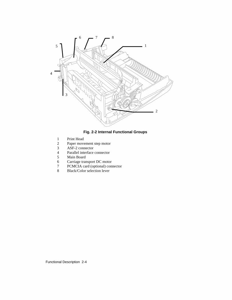
Fig. 2-2 Internal Functional Groups
1 Print Head2 Paper movement step motor3 ASF-2 connector4 Parallel interface connector5 Main Board6 Carriage transport DC motor7 PCMCIA card (optional) connector8 Black/Color selection lever
1
2
3
876
5
4

Functional Description 2-5
2.3 BLACK INK-JET HEAD FUNCTIONING
Ink jet head Description:This consists of an interchangeable sealed container containing 50 print nozzlesand an electric circuit including 50 miniresistors (Fig. 2-3). The nozzles areassembled on a Nickel and Gold composition called "electroformed". These havea conical structure, as illustrated in figure 2-3.
The ink, contained in a sponge cartridge, is connected to the nozzles via channelsin the resin layer of the head. This layer is electrically insulated from theminiresistors. The miniresistors are aligned to the nozzles and connectedelectrically to the external head contacts.
Fig 2-3 Ink jet head - Black
INK JET HEAD&
INK JET CARTRIDGE
Nozzle
NOZZLESELECTION
50µm
140-150µm
Resistor/Nozzle pad
Flexible Electric grid
Ink Cartridge
Ink Jet Head
Container
Ink Sponge
Cover
Resistor
Ink filter

Functional Description 2-6
How an Ink-jet Works:Every single nozzle generates an ink bubble each time the relative resistor ispowered for a few nanoseconds.
When the resistor heats up, the ink touching it evaporates.
This phenomena determines the formation of a bubble which quickly expands andcompresses the remaining liquid inside the nozzle. A part of the ink "bubble" isejected out via the nozzle hole at a speed of approximately 15m/s.
Figure 2-4a/e illustrate the prominent bubble formation and ejection phases.
Once the resistor power supply command is terminated, the evaporated ink bubbleis broken down and a quantity of ink equal to that ejected is reinstored forchanneling in the nozzle vein.
At this point, the eject command for a new bubble can begin.

Functional Description 2-7
NOZZLE
Fig 2-4 Ink Bubble Formation
Fig. 2-4a
INITIAL STATUS
Fig. 2-4b
THE RESISTOR HEATS UP ANDSTARTS TO FORM VAPORBUBBLE.
THE INK EXITS FROM THENOZZLE.
Fig. 2-4c
THE BUBBLE REACHES ITSMAXIMUM DIMENSION.
Fig. 2-4d
THE BUBBLE BREAKS DOWNAND AN INK BUBBLE ISEJECTED.
Fig. 2-4e
THE INK IS RESET, FORCHANNELLING, IN THE NOZZLE.

Functional Description 2-8
The nozzles:The print nozzles (1-50) are placed on two columns, each containing 25 nozzles.They are placed in sequence on each column as illustrated in figure 2-5.
In addition, the matrix is made up of:• A,C and B,D nozzles with 2.50 and 1.49 extreme print nozzle
damper/equilibrator functions.
• E-L cartridge equilibrator nozzles.
Fig 2-5 Nozzle Matrix

Functional Description 2-9
Resistors actuation circuit specifications:The resistors are divided into four groups; two of which contain 12 resistors andtwo 13. Each group can be controlled by only one resistor at a time and thereforeno more than 4 resistors can be controlled simultaneously.
In addition, to avoid induction phenomenon’s between adjacent resistors/nozzles,the drive will be carried out in a particular sequence (Fig. 2-6).
Fig 2-6 Resistor drive sequence
Each resistor group is controlled by a 18.8 V driver circuit. For correct headfunctions, the above voltage must be stabilized.
Characteristic disadvantages which could occur with lower voltages are: lack ofbubble ejection if the head is not used for a short period, lack of bubble ejectionwith low temperature. Higher voltage may provoke excess bubble commands orthe absence of command due a resistor deterioration.

Functional Description 2-10
2.4 COLOR INK-JET HEAD FUNCTIONING
Color Ink jet head Description:The color ink jet head has a replaceable sealed container that contains 51 printingnozzles, three liquid ink containers, one for each basic color, and an electriccircuit with 51 miniresistors (Fig. 2-7a).
The nozzles are divided as follows between the three basic colors:
- Yellow: 18 nozzles- Magenta: 17 nozzles- Cyan: 16 nozzles
The nozzle construction technology is the same as for the monochrome ink jet:they are obtained from a Nickel and Gold compound called "electroformed". Theyhave a tapered structure as can be seen in figure 2-7b.
The ink is in three containers, one for each color.
Inside each of these containers there is a sponge to prevent the ink from shakingwhen the head is moving thus avoiding possible interference in the carriagetranslation, spillage from the vent holes and the formation of froth.
The ink arrives at the corresponding nozzles through channels in the resin layerof the head. This layer is electrically isolated from the miniressitors.
The miniresistors are positioned to correspond to the nozzles and are connectedelectrically with the head external contacts.

Functional Description 2-11
Fig 2-7 Color head
Fig 2.7a - Ink jet Headfor Color Inks
50µm
140-150µm
Nozzle
Fig 2.7b Nozzle Section
Resistor/Nozzle Pad
Flexible Electric grid
Ink filter
Ink Cartridge
Ink Sponges

Functional Description 2-12
Ink jet printing functioning principle:See section 2.8 where this has already been dealt with.
The nozzles:The print nozzles (1-51) are placed vertically on two columns, containingrespectively 25 and 26 nozzles , and horizontally in three groups, one for eachcolor.
They are placed in sequence on each row of nozzles as illustrated in figure 2.8.
Yellow
Magenta
Cyan
44
46
48
50
20222426
19212325
45474951
1357
2468
Fig 2-8 Nozzle Matrixes

Functional Description 2-13
Resistor enabling circuit specifications:The resistors are divided into four groups; one contain 12 resistors and the otherthree 13. Each group can be controlled by only one resistor at a time and thereforeno more than 4 resistors can be controlled simultaneously.
To avoid induction phenomenon’s between adjacent resistors, the drives arecarried out in the sequence illustrated in figure 2-9.
Fig. 2-9 Resistor drive sequence
Each resistor group is controlled by an 18.8 V driver circuit. For correct headfunctioning, the above voltage must be stabilized.
Characteristic disadvantages which could occur with lower voltages are: lack ofbubble ejection if the head is not used for a short period, lack of bubble ejectionwith low temperature.
Higher voltage may provoke excess bubble commands or the absence ofcommand due to resistor deterioration.

Functional Description 2-14
2.5 OPERATING CONTROLS
Operator PanelThe machine console has seven buttons and eight light emitting diodes (LED).
OnlineInk/
PaperSupply
Color
Manual ASF1 ASF2
Tractor
LQ NLQ Draft
Install
Cartridge
Selection
Print Quality
Portrait Paper Paper
Landscape Micro-Advance
Load-Eject
Paper Device
Fig 2-10 Operator panel
The keys (A/G) are used for the paper handling (load, feed, horizontal and verticalformat), to set the print quality and to replace the ink cartridge.
The LEDs (1/8) indicate the machine status, end of paper/ink or an error message.
For full details as to the operation and meaning of the keys and LEDs on thispanel, see the Fault Sympton and Solution section number 6.
1
2
3
4
5
67
8
A B
C
D E
G F

Functional Description 2-15
Key functionsThe key functions in the different machine operating modes are given below.
Some functions require that more than one key must be pressed simultaneously orin sequence, either while the machine is functioning or when it is powered up.
A ON LINE Toggles the printer between ON LINE and LOCAL operatingmodes
LED 1 indicates the machine status.Keeping the key pressed at machine power-on (with paperpresent) it activates the print test.
B INSTALL Moves the print carriage to the position for changingCARTRIDGE the head or the ink cartridge.
LED 2 indicates the replacement request. LED 3 warns whenthere are head change errors.
Keeping the key pressed at the machine power-on activateshexadecimal printing.
C PORTRAIT/LANDSCAPEWith the printer in ON LINE and without data for printing(empty buffer) it alternates the vertical horizontal print modesthat are indicated by LED 4.
Keeping the key pressed at machine power-on (with paperpresent) the bi-directional print alignment function isactivated.
D PAPER DEVICE/ PRINT QUALITYWith the machine in ON LINE and without data to print ittoggles PAPER DEVICE and PRINT QUALITY selectionmodes indicated by LED 5.
E SELECTION Selects the paper feeding device/print quality.
The parameter selected is indicated by LED 6, 7, 8

Functional Description 2-16
F PAPER LOAD-EJECTControls the paper feed on the selected device.If the printer is in ON LINE and paper is present:
-with manual or ASF feed and data to be printed in thebuffer, but waiting for a Form Feed command, it forces theprint of an unconcluded page and its ejection;
-with Sprocket paper feed and data to be printed in the bufferbut waiting for a Form Feed command, it forces the print ofan unconcluded page and feeds the continuous module to thenext first print position (TOF).
If the printer is in LOCAL and paper is present:
-with manual paper feed or ASF the sheet is ejected.
-with Sprocket it feeds the continuous module as far as thenext first print position (TOF).
If there is no paper in the printer, regardless of the operatingstatus:
-in manual paper feed or ASF it tries to insert a sheet in theprinter
-with Sprocket it tries to feed the continuous module as far asthe first print position (TOF).
G PAPERMICRO-ADVANCEWith the machine in ON LINE mode and without data to beprinted (empty buffer) or in LOCAL mode, it advances thepaper by one elementary unit (1/150").Keeping the key pressed the paper continues to advance untilthe key is released.
B INSTALLCARTRIDGE + C PORTRAIT/ LANDSCAPEKeeping these two keys pressed at machine power on the firstfile that is transmitted to the printer will be interpreted as aconfiguration file (see section 8.3).

Functional Description 2-17
B INSTALL CARTRIDGE + D PAPER DEVICE / PRINT QUALITYKeeping these two keys pressed at machine power on, theprinter configuration parameters set in the factory will berestored (default parameters).
B INSTALL CARTRIDGE + G PAPER MICRO-ADVANCEPressing these two keys simultaneously regardless of theprinter status, a machine reset is carried out (any printingoperation in progress is canceled and the data in the buffer islost).

Functional Description 2-18
2.6 COLOR SELECTION LEVERThe color selection lever is on the right-hand side of the machine, under the uppercover compartment.
The lever is usually directed towards the operator (BLACK setting), and in thisposition the printed is equipped with a black ink head.
This lever is only used to indicate the variation to the machine when a color headis installed.
When the lever is changed to COLOR setting, the monochrome print matrixprotection is exchanged with another of a suitable size for the color head aphotosensor is obscured and the electronic board receives the communication tochange the machine setting (change in emulation, head drive and print speed).
The lever is only to be moved when the print head is in cartridge changeposition. If this is not respected there is danger that serious damage is causedto the print carriage and the protection rubber caps exchange kinematics.
To return to monochrome, change the heads and move the lever with the printcarriage always in the cartridge change position.
Fig. 2-11 Color selection lever

Installation 3-1
3. INSTALLATION
3.1 GENERAL INSTRUCTIONSThe following rules must be observed to guarantee optimum printer functioningand to avoid service for reasons not attributed to the product:
Mains power supply:The LJ 500 and LJ 520 printers conform to the safety standard, ergonomicsand the electromagnetic interference (EMI) imposed by the followingorganizations:
Safety: USA/ UL/ UL 1950/ 478 standardItaly IMQ/ CEI 74.1 and IEC 380 standardsCanada/ CSA/ C22- 2 n 220 standardScandinavia/ NEMKO/ EN 60950 standard
Ergonomics T.U.V./E.R.G. G.S.Gi.d.f vom 1979
EMI Germany/ VDE/ DBP verf. 243/1991 standardCEE/ CEE 87/308/ EN 55022 Class BUSA/ FCC/ FCC part 15 Class. B standard.:
Do not connect the printer to common power supply lines or industrial apparatus,as the electrical variations are higher and the static greater, than that tolerated bythe printer.
Environmental conditions:The printer can remain indefinitely in environmental conditions as indicated bythe AB quality objectives (normal office environment). When operating, avoidany temperature variations that could cause condensation.
Product positioning:The printer must be installed on a flat, steady surface. Do not expose the printer toventilators, heat sources or direct sunlight. The latter instruction is especiallyimportant when using ink jet printers.

Installation 3-2
3.2 UNPACKING
Packing check:Unpack the contents of the carton and check them against those illustrated in thefollowing. Retain the carton and packing materials for future use should you needto relocate the printer at any time.
If anything is missing or damaged, call your supplier immediately.
4
8
5
10
3
210
9
1
7
Fig 3-1 Package Contents
1. Printer 6. Driver diskette
2. Power cable 7. Black print head
3. Paper stop 8. Color print head*
4. Paper input tray 9. Storage box*
5. User manual 10. Read me first
* only for LJ 520
9

Installation 3-3
3.3 CONNECTION TO THE MAINSConnect the mains power supply cable supplied with the printer first making surethat the voltage indicated on the label plate corresponds to that of the localnetwork.
To ensure optimal machine operation, check with the instructions given in section3.1.
3.4 INSTALLING THE PRINT HEADThe print head is composed of two parts: an external wrapping and a throw-awayink cartridge. The head has an "ink presence" sensor that guarantees the constantprint quality, giving timely indication when the cartridge is finished.
To install the print head:
1. Power up the printer. The INK-PAPER SUPPLY LED will blink toindicate that there is no print head.
2. Press the INSTALL CARTRIDGE push-button to position the carriagefor head change.
3. Lift up the machine upper cover.
4. Open the container and remove the head, taking care not to touch theelectric contacts.
5. There is an "Operating guide" printed inside the container that describesthe installation procedure.
Fig. 3-2 Opening the head container

Installation 3-4
6. Holding the cartridge by the grip, remove the protective label from thenozzles.
7. Insert the cartridge in place, pushing it first down and then forward.
1 2
Fig. 3-3 Inserting the head into the machine
8. Close the machine upper cover.
9. Press the INSTALL CARTRIDGE key again: the print head will go to itsparking position (right-hand end of stroke) and the machine checks thecoherence between the installed head and the black/color lever setting. Ifthe setting is correct, the COLOR LED will indicate the type of headinstalled (on = color, off = black) if there is an error, this will beindicated by the blinking of the INSTALL CARTRIDGE LED.

Installation 3-5
3.5 INSERTING AN OPTIONAL MEMORY/FONT CARDThe memory/font cards handled by this printer conform to PCMCIA standard(Personal Computer Memory Card International Association).
The cards contain a firmware emulation or an EPROM relevant to a characterfont group or an additional memory (RAM or Flash EPROM).
The card can be added after the printer has been installed. The card features andcorresponding installation procedures are described in the appropriate manual,included in the same package as the memory card.
Switch the printer off before inserting a card.
After inserting a memory card with optional emulation, only its codes arerecognized. To reselect the basic emulation, PCL3, remove the memory card.
The cards containing character fonts are specific for the basic emulation,PCL3, and are not, therefore, handled by IBM Proprinter 4207 and EpsonLQ 850 optional emulations.
To install the memory card, proceed as follows:
Switch off the printer
Insert the memory card into the specific slot
Switch on the printer
If the memory card contains an emulation, program the new set upparameters; if the memory card contains an optional font, select theexternal font.
Fig. 3-4 Inserting the memory card

Installation 3-6
3.6 PAPER FEED
ASF sheet feed:The sheets are fed into the machine using the ASF drawer on the machine.
The drawer can hold 120 sheets of 80 g/m2 paper.
Sheets from 60 g/m2 to 90 g/m2 can be handled.
The printable area for the most common formats A4 and Letter/Legal can beobtained from the table below.
A4 Letter/Legal
mm inches mm inches
M 210 8.26 215.9 8.5
L 203.2 8 203.2 8
S 3.4 0.134 6.4 0.25
D 3.4 0.134 6.4 0.25
T 1 0.04 1 0.04
B 12.7 0.5 12.7 0.5

Installation 3-7
For ASF sheet feed, follow this procedure:
- Take the ASF drawer from the machine
- Insert the sheets (maximum 120) into the drawer
- Adjust the drawer side guides (1) according to the width of the sheets
US
12
3
Fig. 3-5 Drawer guides adjustment
- Insert the drawer into the machine
- If A5 or Letter size format is used, insert the paper stop in the appropriateholes in the drawer
Fig. 3-6 Inserting the drawer into the machine
- Switch on the printer
- Press the PAPER LOAD/EJECT key to feed a sheet into the machine.

Installation 3-8
Manual insertion:Manual paper feeding is through the rear slot on the machine which is accessed bylifting the rear cover. The machine will accept sheets and envelopes up to 135g/m2.
The printable area for the most commonly used envelope sizes: C5, DL, C#10 andC6 can be obtained from the table below.
C5 DL C#10 C6
mm inches mm inches mm inches mm inches
M 228.6 9 22 8.66 241.3 9.5 162 6.38
L 203.2 8 203.2 8 203.2 8 162 6.38
S 12.7 0.5 6.4 0.25 25.4 1 - -
D 12.7 0.5 6.4 0.25 25.4 1 - -
T 1 0.04 1 0.04 1 0.04 1 0.04
B 12.7 0.5 12.7 0.5 12.7 0.5 12.7 0.5

Installation 3-9
To insert the document manually, follow this procedure:Lift the printer rear cover to have access to the manual feed slot
Fig. 3-6 Opening the rear cover-With the printer switched on, insert the document into the manual feed slot
so that it touches the feed rollers.
Fig. 3-8 Manual sheet feed
Press the PAPER LOAD-EJECT key to insert the document into the machine
Send the text for printing from the system.

Installation 3-10
3.7 SPROCKET INSTALLATIONThe sprocket is an option that can be installed by the operator.
It is fitted into the machine near to the manual feed slot, removing the rear part ofthe casing and taking out the prepared marked part so as to have access to themovement socket. Install the option inserting it in the relevant guides.
Detailed instructions are contained in the packing together with the device.
"Tractor" must specified using the parameter set-up procedure, or selected usingthe PAPER DEVICE and SELECTION keys on the console(LEDs ASF1+ASF2lit).
Paper loading by sprocket:The sprocket can be used for continuous paper feed or for single sheets.
The printable area for continuous modules can be obtained from the table below,together with the figure that illustrates the meaning of the values in the table.
mm inches
M=P 241.3 9.5
L 203.2 8
S 19 0.75
D - -
T 1 0.04
B 1 0.04
To insert the continuous paper by Sprocket use the following procedure::
Lift the paper feed roller covers and insert the paper so that the feedholes are held by the feed roller pins, then close the covers.
Space the two feed rollers so they tension the paper roll correctly.
Use the PAPER DEVICE and SELECTION keys to enter the paper feedby sprocket (TRACTOR) through the console or select "TRACTOR" inthe set-up parameters.

Installation 3-11
3.8 2nd PAPER TRAY (ASF2) INSTALLATIONASF2 is an optional 2nd paper tray that can be installed by the operator. It ispositioned under the machine base and is connected to the motherboard by a cablewhich has to be connected.
Detailed instructions for the installation are provided in the package together withthe device.
Remember that the machine must be switched off when installing this device.
To feed the paper from ASF2 it is necessary to select feeding from this option inthe set-up parameters.
Paper insertion from second ASF drawer:The ASF2 has a paper feed drawer, like the integrated ASF. This drawer also hasa capacity of 120 sheets of 80 g/m2 paper.
It can handle sheets from 60 g/m2 to 90 g/m2.
The printable area is the same as for the integrated ASF (see page 3-6).
To insert the sheet from the second ASF the procedure is as follows:
Remove the ASF drawer from the machine
Insert the sheets (max. 120) into the drawer
Adjust the drawer side guides according to the width of the paper
Insert the drawer into the machine
Switch on the printer
Use the PAPER DEVICE and SELECTION keys to set the paper feedfor the second ASF (ASF2) through the keyboard.

Installation 3-12
3.10 SERIAL INTERFACE INSTALLATIONThe serial interface is an option that can be installed by the operator.
Detailed instructions for the installation are supplied in the package with thedevice.
With the serial interface option connection to the system can be either serial orparallel. To make the choice it is only necessary to select the type of interface inthe machine set-up. The figure below shows the 25-pin Cannon connector usedto connect the serial interface, indicating the transmission signals.
14
15
16
17
18
19
20
21
22
23
24
25
1
2
3
4
5
6
7
8
9
10
11
12
13
PROTECTIVE GROUND
TRANSMITTED DATA
RECEIVED DATA
DATA SET READY
ADYSIGNAL GROUND
DATA TERMINAL READY

Installation 3-13
3.11 PRINT TESTTo verify the correct printer installation the print test should be made, asdescribed below:
Feed the ASF drawer with paper, preferably size A4
Switch off the machine then switch on keeping the ON LINE keypressed during power up.
The printer will start to feed the paper and print the test on four sheets.
The test finishes after the four pages have been printed and the machineis then ready for connection to the system.
With this test it is possible to verify the machine functioning and to know theprinter default set-up parameters.
3.12 SYSTEM CONNECTION
Centronics parallel interfaceThis interface is provided in standard mode on the printer and therefore does notrequire any further optional devices.
The data exchange synchronization (handshaking) is implemented via thecharacter strobe signal issued from the system, and the busy signal emitted fromthe printer.
DATA
STROBE
BUSY
ACK
Tack
Ts TdTd
Installation 3-14
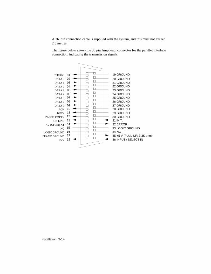
A 36 pin connection cable is supplied with the system, and this must not exceed2.5 metres.
The figure below shows the 36 pin Amphenol connector for the parallel interfaceconnection, indicating the transmission signals.
19 GROUND20 GROUND21 GROUND22 GROUND23 GROUND24 GROUND25 GROUND26 GROUND27 GROUND28 GROUND29 GROUND30 GROUND31 INIT.32 ERROR33 LOGIC GROUND34 NC35 +5 V (PULL-UP; 3.3K ohm)36 INPUT / SELECT IN
D 17
E 10
T 14
Y 12
D 16
E 01
1 032 043 054 065 076 087 09
Y 11
C 15
V 18
E 13
0 02STROBEDATA 0DATA 1DATA 2DATA 3DATA 4DATA 5DATA 6DATA 7
ACKBUSY
PAPER EMPTYON LINE
AUTOFEED XTNC
LOGIC GROUNDFRAME GROUND
+5 V

Installation 3-15
3.13 SWITCHING OFF THE PRINTERBefore switching off the printer, ensure that the head is positioned to the far rightof the guide rail. This status is automatically obtained every time the printer isinactive for a few seconds, hermetically sealing the print nozzles and thuspreventing the ink inside the nozzles from drying up.
3.14. INSTALLATION SET UPThe printer can be configured using a print driver that corresponds to the basic HPDJ 500C. emulation
For utility programs working in DOS environment the printer set-up can becarried out (if there is no suitable print driver) using a very simple mini-programcontained in the DOS diskette that is included in the machine packing.
For the Windows 3.1 environment a diskette is supplied with the printer thatcontains the specific driver that uses the machine potential to the full. For thecolor option, the pack also includes a driver for color printing.
If the printer is not configured by the system, it will use the parameters set in thefactory (Default).

Installation 3-16
DEFAULT parametersTo verify the parameters set up in the factory the print test can be run, printing thefour pages that show the default setting and the print fonts available.
To run this test, see section 5.2. The following values are set up in the factory:
Paper Format A4
Paper Device ASF1
Perforation Skip Enabled
Text Scale Mode Disabled
Always Bidir. Disabled
Ink Save Mode Enabled
BIM Density 75 dpi
Line Terminator Normal
Print Quality LQ
Width Type OFF
Type Style Courier Upright 10 12 Portrait
Character Set CP 437 International
The following parameters are only included if the serial interface option isinstalled, to which these parameters refer:
Baud Rate 9600
Parity None
Handshaking Hardware
Installation 3-17
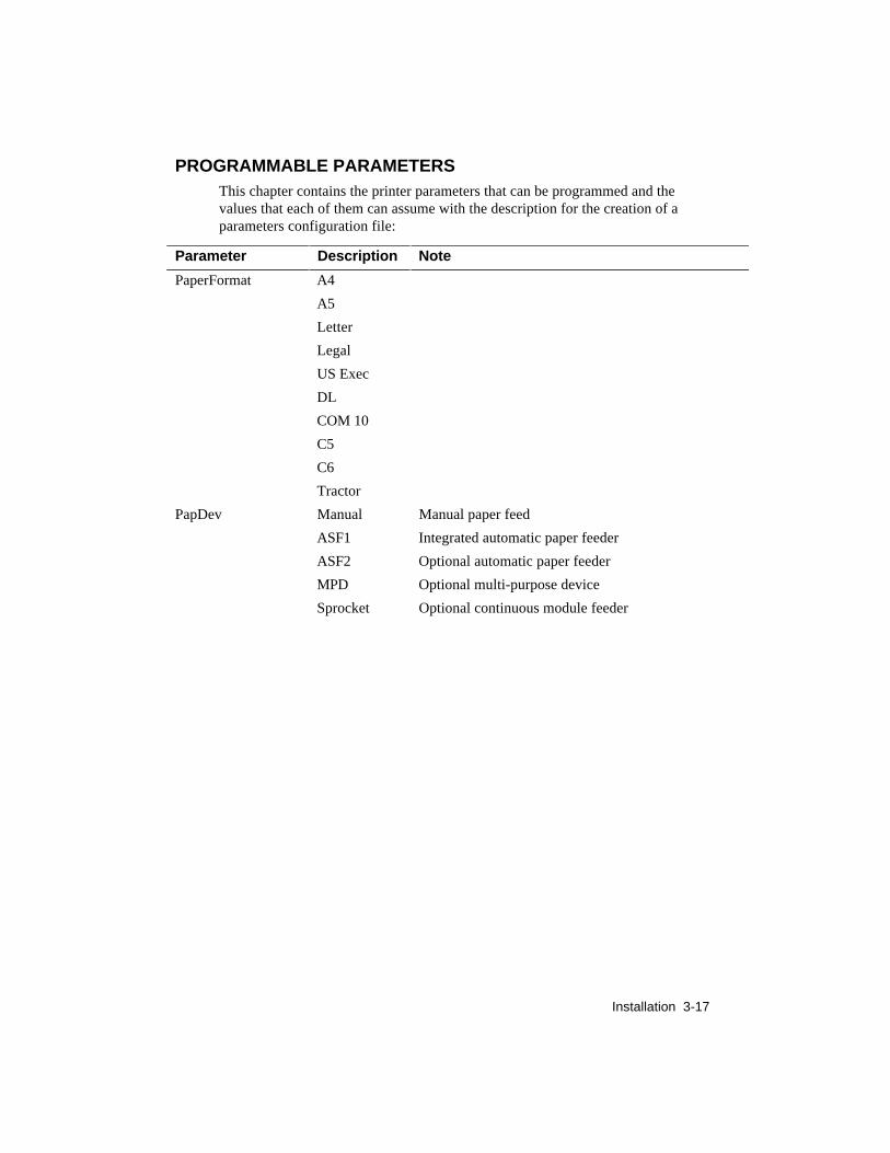
PROGRAMMABLE PARAMETERSThis chapter contains the printer parameters that can be programmed and thevalues that each of them can assume with the description for the creation of aparameters configuration file:
Parameter Description Note
PaperFormat A4
A5
Letter
Legal
US Exec
DL
COM 10
C5
C6
Tractor
PapDev Manual Manual paper feed
ASF1 Integrated automatic paper feeder
ASF2 Optional automatic paper feeder
MPD Optional multi-purpose device
Sprocket Optional continuous module feeder

Installation 3-18
Parameter Description Note
PerSkip Off Paper skip disabled (TOF= 0, BOF= printing
continues to the last line of the page)
On Paper skip enabled (TOF= 12.7 mm - 0.5";
BOF= 12.7 mm - 0.5")
TextScale Off Nominal line feed value
On Reduced line feed value to increase the number oflines per printed page
AlwaysBidir Off Bi-directional print, if possible
On Always bi-directional print
InkSaveMode Off Feature disabled
On Reduces the ink consumption
Bimdensity 75 75 dpi (dots per inch)
100 100 dpi
150 150 dpi
300 300 dpi
Terminator Normal CR = CR, LF = LF, FF = FF
AutoLF CR = CR+LF LF = LF, FF = FF
AutoCR CR = CR, LF = LF+CR, FF = FF+CR
AutoCRLF CR = CR+LF, LF = LF+CR, FF = FF+CR
Quality LQ Letter Quality
NLQ Near Letter Quality
Draft Draft
Parameter Description Note
WidthType Normal Normal size
HalfWidth Compressed characters
HalfHeight Half height
HalfWidthHeight
Compressed -half height

Installation 3-19
Parameter Description NoteTypeStyle 1 Courier Upright Portrait 10 cpi 12 pts
2 Courier Italic Portrait 10 cpi 12 pts3 Courier Upright Portrait 16,67 cpi 12 pts4 Letter Gothic Upright Portrait 10 cpi 12 pts5 Letter Gothic Upright Portrait 12 cpi 12 pts6 Letter Gothic Italic Portrait 12 cpi 12 pts7 Letter Gothic Upright Portrait 16,67 cpi 9,5pts8 TMS Nordic Upright Portrait PS 12pts9 TMS Nordic Italic Portrait PS 12pts10 BF Times Upright Portrait PS 14 pts11 BF Times Italic Portrait PS 14 pts12 BF Times Upright Portrait PS 12 pts13 BF Times Italic Portrait PS 12 pts14 BF Times Upright Portrait PS 10 pts15 BF Times Italic Portrait PS 10 pts16 BF Times Upright Portrait PS 8 pts
17 BF Times Italic Portrait PS 8 pts
18 Linea Upright Portrait PS 14 pts19 Linea Upright Portrait PS 12 pts20 Linea Italic Portrait PS 12 pts21 Linea Upright Portrait PS 10 pts22 Linea Italic Portrait PS 10 pts23 Linea Upright Portrait PS 8 pts24 Courier Upright Landsc 10 cpi 12pts25 Courier Italic Landsc 10 cpi 12pts26 Courier Upright Landsc 16,67 cpi 12pts27 Letter Gothic Upright Landsc 12 cpi 12 pts28 Letter Gothic Upright Landsc 16,67 cpi 12 pts100/199 External fonts (see options list)

Installation 3-20
Parameter Description Note
Charset 0 The selected character set remains unchanged
1 CP 437 International
2 HP Roman 8
3 PC-8 Denmark/Norway
4 CP 850 (Multilingual)
5 ECMA 94 Latin
6 ISO 4 United Kingdom
7 ISO 21 Germany
8 ISO 69 France
9 ISO 15 Italy
10 ISO 60 Norway 1
11 ISO 61 Norway 2
12 ISO 11 Sweden Names
13 ISO 10 Sweden
14 ISO 17 Spain
15 ISO 6US ASCII
16 ISO 2 IRV
17 ISO 16 Portugal
18 ISO 14 JIS ASCII
19 Legal
20 CP 860 Portugal
21 Danish OPE 1
22 UNIX International
23 Danish OPE 2
24 Spain II
25 CP 863 French Canadian
26 PC Win ANSI Windows 3.1
27 CP 852 Latin 2
28 ISO 8859/2 Latin 2
29 PC Win East European Windows 3.1
Installation 3-21
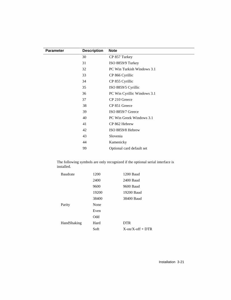
Parameter Description Note
30 CP 857 Turkey
31 ISO 8859/9 Turkey
32 PC Win Turkish Windows 3.1
33 CP 866 Cyrillic
34 CP 855 Cyrillic
35 ISO 8859/5 Cyrillic
36 PC Win Cyrillic Windows 3.1
37 CP 210 Greece
38 CP 851 Greece
39 ISO 8859/7 Greece
40 PC Win Greek Windows 3.1
41 CP 862 Hebrew
42 ISO 8859/8 Hebrew
43 Slovenia
44 Kamenicky
99 Optional card default set
The following symbols are only recognized if the optional serial interface isinstalled.
Baudrate 1200 1200 Baud
2400 2400 Baud
9600 9600 Baud
19200 19200 Baud
38400 38400 Baud
Parity None
Even
Odd
HandShaking Hard DTR
Soft X-on/X-off + DTR

Installation 3-22
SYSTEM PARAMETER SET-UPIf it is necessary to change a configuration parameter, the procedure is as follows:
• With the PC and the aid of an ASCII based word processor or a file editor,create a file "XXXX" to write the parameters and descriptions that you wantto enter.
-When creating the configuration file pay attention to:
- use a new line for each parameter with its relevant description separate eachparameter from its description by a blank, a tabulation or an equal sign (=)
- the last line of the file must be "END" followed by a return with a line feed.
- To transmit the parameters to the printer:
- Switch on the machine keeping the INSTALL CARTRIDGE andPORTRAIT-LANDSCAPE keys pressed until the initialization is completed.
- Send the parameters configuration file from the PC to the printer with thecommand: copy "XXXX" prn
• The printer will configure according to the parameters received from the PC.
Run the print test to verify the machine configuration.

User Maintenance 4-1
4. USER MAINTENANCE
No special preventive maintenance is required. However after any servicing it isadvisable
- to ensure there is no trace of ink on the print head nozzlesurface. If there is, clean and if necessary, replace the rubber capand the cleaning wiper.
- check the orthogonality and the total adherence between thepump rubber cap and the external surface of the nozzle.
- remove any paper or ink residue from inside the machine
DO NOT TOUCH OR CLEAN THE NOZZLE OR ELECTRIC HEADCONTACTS MANUALLY. IF NECESSARY, CLEAN USING A RAGDAMPENED WITH ALCOHOL OR A CLEAN BRUSH.
4.1 NOZZLE CLEANING AND INK RESET (“PRIME”)The external surface of the nozzles is cleaned automatically by the printer duringthe paper movement. The user is responsible for the ink reset operation when oneor more nozzles are clogged.
The gradual nozzle check made during the print test (section 5.2) is very helpfulto detect faulty nozzles.
Nozzle cleaning:Nozzles are cleaned by the rubber wiper located at the right-hand end of the headstroke. During the printout intervals for paper movement, when the head iscontrolled by the parking area, before sealing, the nozzles graze the rubber capand are cleaned of any ink particles or paper dust.

User Maintenance 4-2
Ink reset ( ”PRIME” ) Black Head Only:This must be carried out when one or more nozzles no longer print. This operationis not required when the initial characters of the printout are incomplete, as this isprobably caused by the printer having been left inactive for a certain period.
Ink reset is not required for the color heads, as there is an automatic nozzlecleaning cycle that takes place at each head change and machine power on.
The "PRIME" operation ejects a small quantity of ink. It is important that the“PRIME" operation is performed only when strictly necessary, to avoid ink beingwasted and therefore reducing the cartridge life.
Do not carry out the ”PRIME” operation if the mechanical groups aredisconnected from the base. If the ”PRIME” slide receives the command with theink discharge tube disconnected from the blotting pad, any object or clothes nearit may be splashed with ink.
To enable the ink reset, set the printer to local mode (in this status the nozzles arealigned to the rubber cap connected to the ink discharge tube).
Push the slide back and forth as shown in the figure, until some ink is seen (one ortwo centimeters) in the tube below the slide.
PUSH
The motion of the slide compresses and releases the tube, forcing the inkdischarge and extraction. Press INSTALL CARTRIDGE to move the print headcarriage to the head loading position, and move the slide backwards and forwardsto empty the tube.
Press INSTALL CARTRIDGE to return the print head carriage to its rest position.
Run the print test to check the quality of printing.

User Maintenance 4-3
Black Ink jet head cleaning and maintenance:The ink jet head requires particular care as far as cleaning the nozzles areconcerned.
Given their particular structure, the nozzles are likely to get clogged with dust or,if exposed, dried ink.
Some useful tips to guarantee the best use of the head are listed below:
• Only remove the head from its wrapper when about to insert it into theprinter. The head is guaranteed for approximately 18 months if preservedin its sealed container and for approximately 6 months if unprotected (thetwo periods are cumulative).
• Do not place the head on the nozzle or on the electric contacts.
• Do not place the head on heat sources, air conditioners or dusty or dirtysurfaces.
• If necessary (nozzles clogged), carry out the ”PRIME” command(section 4.1).
• The purpose of this command is to suck some ink through the nozzles toremove any dirt. This command should be carried out each time one ormore nozzles become clogged.
• On termination of a print operation, hermetically seal the nozzle area toprotect them from dust and to prevent the ink from drying. Thisoperation is automatically carried out on the printer if it is inactive for afew seconds, therefore, wait a few seconds after the last printout beforeswitching off the machine.
• In the case of a power failure, after switching off the printer, push thehead by hand to the right, to the end of its stroke.
_______________________ Note _____________________________
If the computer is switched off while the printer is still switched on,the printer will reset. If the printer is switched off during this reset, theprint head may not stop in its rest position.Always switch off the printer before switching off the computer.

User Maintenance 4-4
Color head cleaning and maintenance:The color head also requires particular care as far as cleaning the nozzles areconcerned.
Given their particular structure, the nozzles are likely to get clogged with dust or,if exposed, dried ink.
Some useful tips to guarantee the best use of the head are listed below:
• Only remove the head from its sealed wrapper when about to insert it intothe printer. The head is guaranteed for approximately 18 months ifpreserved in its sealed container and approximately 6 months ifunprotected (the two periods are cumulative).
• Do not place the head on the nozzle or on electric contacts.
• Do not place the head on heat sources, air conditioners or dusty or dirtysurfaces.
• After a new color head has been installed the machine automatically runsa nozzle cleaning cycle, so the PRIME operation is not necessary forcolor heads.
• On termination of the print operation, hermetically seal the nozzle area toprotect the nozzles from dust and to prevent the ink from drying. Thisoperation is automatically carried out on the printer if it is inactive for afew seconds, therefore wait a few seconds after the last printout beforeswitching off the machine.
• In the case of a power failure, after the printer has been switched off,push the head by hand to the right until it reaches its end of stroke.
• Whenever the color head is removed from the machine, take care to placeit in the "Service station "supplied with the color kit: this will ensure thatthe head ink has the maximum protection against drying .
_______________________Note:_________________________
If the computer is switched off while the printer is still switched on,the printer will reset. If the printer is switched off during this reset, theprint head may not stop in its rest position.
Always switch off the printer before switching off the computer.

Diagnostics and Test 5-1
5. DIAGNOSTICS AND TESTS
5.1 AUTODIAGNOSTICS AT POWER-ONThe machine firmware automatically tests the main functions of the machine ateach power on.
If any faults are found they are indicated by all the LED s blinking on theconsole (see Section 6 for LED fault indications).
5.2 PRINT test with black print headThis test verifies the correct functioning of the head, it displays the machineoperating parameters and visualizes the printer character fonts available .
The test supplies the following information:
- type of emulation selected and firmware release on the machine.
- type of print head installed (3600Hz for color head or 5000 Hzfor Black head)
- correct hydraulic functioning of the nozzles (Print Head Test)
If the test indicates that one or more nozzles has no ink bubble,but the Nozzles test is satisfactory, it may be necessary to run aPRIME operation.
- the electric continuity check on the nozzle activation circuit(Nozzles test)
If the test indicates an error in the nozzle feed, see the guide todiagnostics section (5.5).
- the printer set-up parameters
- fonts available in Portrait and Landscape modes.

Diagnostics and Test 5-2
To run this test, proceed as follows:- Load the ASF drawer with paper, preferably A4
- Switch off the machine then switch on keeping the ON LINEkey pressed during the power on.
The printer will start to feed the sheets and print the test. The first page (as wouldbe printed with a black print head) is shown below:

Diagnostics and Test 5-3
To interrupt the test, press ON-LINE, then press again to continue printing.
To stop the test before it is finished, switch off the machine or make a reset (pressthe INSTALL CARTRIDGE key followed by PAPER MICRO-ADVANCE).
The test ends automatically after the four pages have been printed and themachine remains in ON LINE.
5.3 PRINT test with COLOR print HEADThere is a reduced print test for the color print head that only tests the functioningof the print nozzles .
First the electrical functioning of the nozzles is tested and the result is given by ashort line in blue if no faults are found, or in red to indicate the presence offaults.
For faults found, see the diagnostics guide (section 5.5).
The hydraulic functioning of the nozzles is checked printing three lines using all51 nozzles. The last of these three lines must not have any white lines in thecolored bands. If there are, switch off the printer then run a new print test.
The procedure to run this test is the same as for the monochrome head (section5.2).
The next page shows an example (monochrome) of the print test for the colorhead.

Diagnostics and Test 5-4
5.4 ”DATA SCOPE” PRINTOUT (HEX DUMP)This function prints any incoming character with the corresponding ASCII codes(hexadecimal), thus enabling a verification of the receiving of the control codessent by the system.
Enabling the Data Scope printout:Switch off the printer, press the INSTALL CARTRIDGE key and keeping thekey pressed switch the printer on again.
Disabling the Data Scope printout:To interrupt the hexadecimal printing, press the ON LINE key, to start up againfrom where the printer left off, press the key once more.
To exit from this type of printout, switch off the machine or make a reset (pressthe INSTALL CARTRIDGE key and then also the PAPER MICRO-ADVANCEkey).

Diagnostics and Test 5-5
5.5 DIAGNOSIS GUIDELINESThe diagnosis guidelines list some of the more important error symptoms andprovides a description of the probable causes.
These faults, the symptoms and probable causes have been divided into thefollowing groups:
- Faults at power-on:
Includes all faults corresponding to Vac/Vdc power supply circuits and controlcircuits.
When the printer is switched on and nothing happens (no LED is lit and nomechanical movement occurs) check that the local network system is notdisabled. Switch the printer off and then on again to check whether the faultpersists.
Next check the power supply board checking the condition of the fuses and thatthere is power to the main board.
Finally, replace the main board.
If the printer does not initialize (enabled at each power-on and clears the printer)and all the LEDs are blinking, check that the paper is not jammed, disconnect theprinter from the system and take out the memory card.
After each of these operations, try switching the printer off then on again.
If the printer does not initialize and MANUAL, ASF1, ASF2 LEDs are blinking,check that the print carriage is running freely.
If the ON LINE LED blinks very quickly at power on, replace the main board.

Diagnostics and Test 5-6
- Print quality faults
Includes all faults which do not block the printer but reduce the print qualityconsiderably.
If characters are printed incomplete with one or two dots missing (the print testdescribed in section 5.2 pin points these characters) first clean the nozzles asdescribed in section 7.
If in the print test the Nozzle Test indicates nozzles that are not electricallyconnected, remove the head and clean the contacts on the carriage and on thehead with a clean brush or a rag damped with alcohol .
If the fault persists replace the print carriage and flat cable, and finally the mainboard
If the printout is smeared or irregular, ensure that the carriage movement issmooth, the carriage belt tension device works correctly, the encoder strip is cleanand check the setting of the driver voltage.
Clean the encoder strip carefully with a rag dampened with alcohol, and, ifnecessary (persistent strains, faded or damaged vertical bars or dog-earredcorners), replace the part (see section 9.11).
If the driver voltage is higher than specified (18.8 V) the head resistors overheatthus shortening their life span.
Furthermore it should be remembered that an excessive increase in theenvironmental temperature could cause smeared printing or irregular bubbleformation.
- Paper feed faults
Includes paper jamming, irregular paper feed and lack of paper movement.
The paper movements are controlled by a step motor. If the paper feed functiondoes not work, check the paper present signal kinematic, the motor transferkinematic from the motor to the paper feed roller, the motor cable and lastlyreplace the main board.
Jamming or irregular feed may be caused by paper residue or foreign bodies alongthe paper path or by an incorrect calibration of the tension of the paper motor belt.
If the paper feed from the drawer is irregular, re-shuffle and turn over the sheets inthe drawer, clean the feed rollers, adjust the side clasps and the rear sheet clasp.

Diagnostics and Test 5-7
- Data transmission faults:
Check that the interface cable is the correct type and that it is not too long (2.5meters for the parallel cable).
Check the connections to the PC and the printer.
Check that the printer configuration parameters are coherent with those requiredby the utility software installed on the PC.


Fault Conditions and Meaning 6-1
6. FAULT CONDITIONS ANDMEANING
Operational StatusThe operational status of the printer can be initially determined by the conditionof the LEDs on the operater panel which is shown below.
The LEDs, labelled 1 to 8, indicate the machine status, end of paper/ink or anerror message. It is mainly these you can use to determine an initial problem
OnlineInk/
PaperSupply
Color
Manual ASF1 ASF2
Tractor
LQ NLQ Draft
Install
Cartridge
Selection
Print Quality
Portrait Paper Paper
Landscape Micro-Advance
Load-Eject
Paper Device
Fig 7-1 Operator panel LEDs and Keys
3
8
7
1
2
5
4
6
Fault Conditions and Meaning 6-2
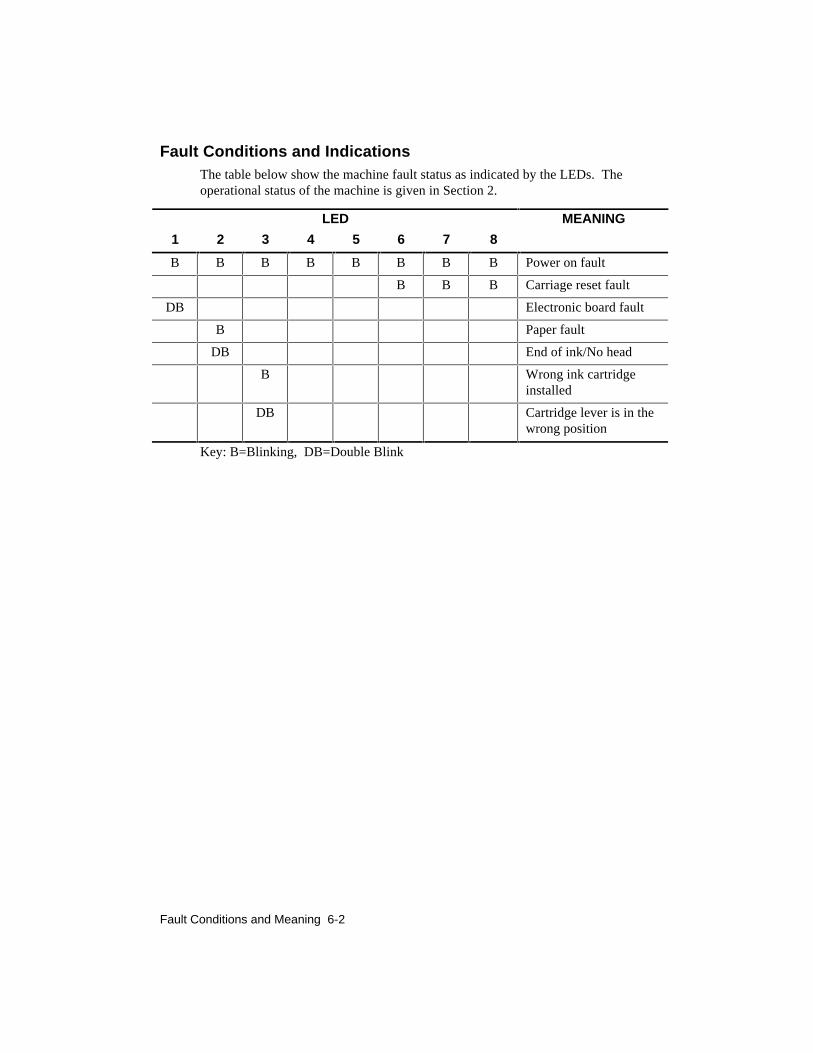
Fault Conditions and IndicationsThe table below show the machine fault status as indicated by the LEDs. Theoperational status of the machine is given in Section 2.
LED MEANING
1 2 3 4 5 6 7 8
B B B B B B B B Power on fault
B B B Carriage reset fault
DB Electronic board fault
B Paper fault
DB End of ink/No head
B Wrong ink cartridgeinstalled
DB Cartridge lever is in thewrong position
Key: B=Blinking, DB=Double Blink

Fault Conditions and Meaning 6-3
Normal Conditions and IndicationsLED MEANING
1 2 3 4 5 6 7 8
OFF LOCAL
ON ON LINE
B ON LINE receiving data
OFF Black cartridge installed
ON Color cartridge installed
OFF Vertical page format
ON Horizontal page format
OFF ON OFF OFF Print quality : LQ
OFF OFF ON OFF Print quality : NLQ
OFF OFF OFF ON Print quality : DRAFT
ON ON OFF OFF Paper feed: Manual
ON OFF ON OFF Paper feed: ASF1
ON OFF OFF ON Paper feed :ASF2
ON OFF ON ON Paper feed : Sprocket
ON ON ON OFF Multipurpose device
Please refer to the functional description part in Section 2 for full details of theoperation of the keys in conjunction with the LEDs.


Mechanical Adjustments 7-1
7 MECHANICAL ADJUSTMENTS
7.1 PRINT HEAD AND THE WRITING SURFACE GAPThe distance between the head and the writing surface and the parallelismbetween the print matrix and the writing surface are obtained using a specific toolwhen assembling the printer.
If the print quality should deteriorate along the writing line, it is advisable tocheck the distance and if necessary, adjust the gap between the print head andprinting surface.
Procedure:To obtain the distance of 1.3 +0.2/0 mm between the head nozzles and thewriting surface, proceed as follows:
- Loosen the screws that fasten the two plastic supports of thecarriage slide bars. The left hand support is loosened throughtwo screws, whereas for the motor support (right) it is necessaryto loose three fastening screws.
- Move the print head carriage, with the print head (even ifempty) loaded, to the extreme left. Using a feeler gage, measure1.3 mm between the print head nozzles and the writing surface.Tighten the screws on the left support.
- Repeat the operation with the printer head carriage at the righthand side.
- Check the measurements both at either end and the middle and,if necessary, adjust.
- Run a print test.

Mechanical Adjustments 7-2
7.2 ADJUSTING THE TENSION OF THE PAPER FEEDMOTOR BELT
The tension of the paper feed motor belt is adjusted during printer assembly, usinga specific tool.
If, during paper feeding irregular line feeds, deformed characters or white stripesalong the printing line occur, check the belt tension and, if necessary, correct it.
Procedure:With all parts mounted, loosen the motor fixing screws so that the motor isslightly blocked.
Rotate the motor anticlockwise so that the rear screw is against the right edge ofits hole.
Using a dynamometer, apply a force of 6 N +/- 0.5 in direction of the pulleyinteraxis (see figure below).
Maintaining the applied force, tighten the motor screws.

Mechanical Adjustments 7-3
7.3 BI-DIRECTIONAL PRINT ALIGNMENTADJUSTMENT
If the printout is badly aligned due to the bi-directional printing, the defect can becorrected by means of the following procedure:
- Make sure there is paper in the machine.
- Power up the printer keeping the PORTRAIT-LANDSCAPEkey pressed.
- The machine will automatically print a series of vertical barsthat permit the bi-directional alignment correction.
- To run this function, read the instructions on the sheet suppliedin the machine.


Electrical Interconnections 8-1
8. ELECTRICALINTERCONNECTIONS
8.1 MAIN BOARD MAIN COMPONENTS
J1 Paper MotorJ2 ConsoleJ3 Parallel InterfaceJ4 Print HeadJ5 Print HeadJ6 Power SupplyJ7 Carriage MotorJ8 ASF2/MPDJ9 Memory CardJ10 Black / Color Head andPaper Presence Photosensors
IC1 Paper Motor DriverIC3 8 Bit BufferIC4 Operational AmplifierIC5 Head DriverIC6 Head DriverIC7 20 V RegulatorIC8 Voltage RegulatorIC9 Head Motor DriverIC10 CPU 80C186XLIC11 ROM 1 MbyteIC12 Dynamic RAMIC13 CATHY ASICIC16 256 Bit EEPROMIC17 LM 393IC20 FLASH EPROMIC21 FLASH EPROM
XT1 20 MHz QuartzZ1 Board data plate

Electrical Interconnections 8-2
8.2 POWER SUPPLY BOARD
Electrical Interconnections 8-3
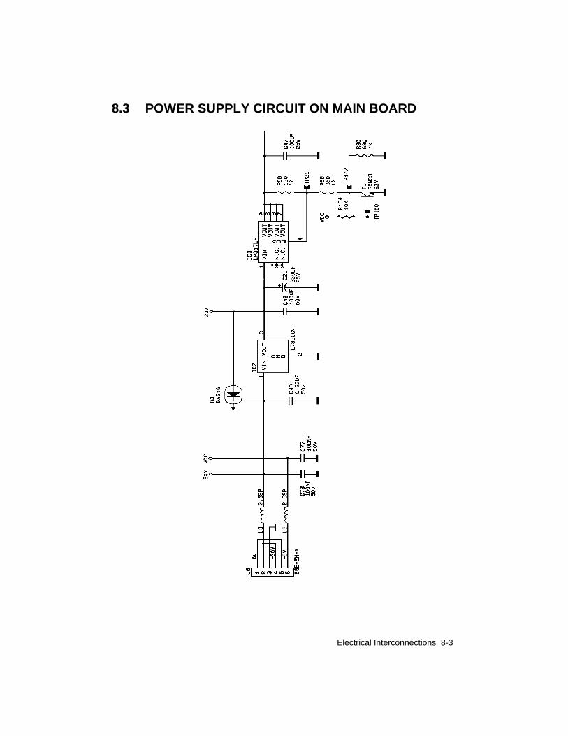
8.3 POWER SUPPLY CIRCUIT ON MAIN BOARD

Electrical Interconnections 8-4
8.4 CONNECTOR SIGNALSMain Board Connector
PAPER
MOTOR
J 1 J 2 J 3 J 4 J 5
1
4
OUT1AOUT1BOUT2AOUT2B
CONSOLE
LED 8LED 7LED 6LED 5LED 4LED 3LED 2KEY GKEY FKEY EKEY DKEY CKEY BKEY ALED 1
1 VCC Q 0 Q 1 Q 2 Q 3 Q 4 Q 5 Q 6 CLV0 CLV1 CLV2 CLV3 CLV4 CLV5 CLV6 Q716
PARALLELINTERFACE
/STRB1 01 19 GNDCD 0 02 20 GNDCD 1 03 21 GNDCD 2 04 22 GNDCD 3 05 23 GNDCD 4 06 24 GNDCD 5 07 25 GNDCD 6 08 26 GNDCD 7 09 27 GND/ACK 0 10 28 GNDBUSY0 11 29 GNDPE 0 12 30 GNDONLINE0 13 31 /INIT 1AUTOFD0 14 32
/ERROR015 33 GND
GND 16 3417 35 /UART
VCC 18 36/SLCTIN
INKREF2 1S50 2C4 3C3 4S49 5RINKREF1 6S47 7S33 8S35 9S45 10S43 11S41 12S37 13S39 14S31 15S29 16S25 17S27 18S23 19S19 20S17 21S21 22S15 23S13 24S11 25S3 26S1 27C1 28S7 29S9 30S5 31NTC 32
CHA 1CHB 2VCC 3GND 4COD1 5S51 6COD2 7S6 8S10 9S8 10C2 11S2 12S4 13S12 14S14 15S16 16S22 17S18 18S20 19S24 20S28 21S26 22S30 23S32 24S38 25S40 26S42 27S44 28S46 29S36 30S34 31S48 32
PRINT HEAD

Electrical Interconnections 8-5
J9 J6 J7 J8 J10
1PAPERGNDIO1GNDVCCVCC6
PAPER /HEAD PHOTOS
1
VCCASFCMD+30VIO2GND6
ASF 2
1OUT1OUT22
CARRIAGE MOTOR
GND 01 35 GNDAD3 02 36 /CD1AD4 03 37 AD11AD5 04 38 AD12AD6 05 39 AD13AD7 06 40 AD14/CE1 07 41 AD15AD10 08 42 /CE2/OE 09 43A11 10 44A9 11 45A8 12 46 A17A13 13 47 P0A14 14 48 P1/WE 15 49 P2
16 50 P3VCC 17 51 VCCVPP1 18 52 VPP2A16 19 53A15 20 54A12 21 55A7 22 56A6 23 57A5 24 58 RSTA4 25 59A3 26 60A2 27 61 /REGA1 28 62 /BVD2A0 29 63 /BVD1AD0 30 64 AD8AD1 31 65 AD9AD2 32 66 AD10
33 67 /CD2GND 34 68 GND
1GND+30VGND+30VGND+5V6
POWER SUPPLY
MEMORY CARD


Electrical Interconnections 8-1
9. PARTSREPLACEMENT
9.1 WARNING NOTES
- sfter servicing, test to ensure that there are no problems on theprinter.
AS A SAFETY PRECAUTION, BEFORE STARTING ANY DISASSEMBLINGOPERATION SWITCH THE PRINTER OFF AND DISCONNECT IT FROMTHE POWER SUPPLY MAINS.
- all operations should be carried out in clean, free areas.
- before switching the printer off, make sure that the head is in theparked position (Carriage on the right).
- when disassembling the head, do not rest it on the contacts ornozzles side; do not touch these parts with your hands.
- to reassemble, follow the disassembly instructions in reverse. makesure that all the connectors have been refitted correctly.
- adjustments after the disassembling/re- assembling of parts is notforeseen EXCEPT FOR THE PRINT HEAD CARRIAGE BARS(SECTION 8.1) AND THE PAPER FEED MOTOR BELT(SECTION 8.2)

Parts Replacement 9-2
9.2 REPLACING THE INK CARTRIDGE:- Open the cover to have access to the print head.
- Press the INSTALL CARTRIDGE key on the console tobring the print head to the change cartridge position.
- Do not remove the print head. Remove only the ink cartridgeusing the black lever on the print head.
- Remove the protective tape from the new ink cartridge.
- Insert the new ink refill immediately, pressing it down until itclicks into place.
- Close the cover and press the INSTALL CARTRIDGE key todelete the end of ink message and set the machine in ONLINE.
_______________________Note: ________________________
Before installing a new cartridge, check the validity date on the sealedwrapping.If the print quality is not the best, run the Prime operation.

Parts Replacement 9-3
9.3 DISASSEMBLING/ RE-ASSEMBLING THE PRINTHEAD:
- Open the cover to have access to the print head.
- Press the INSTALL CARTRIDGE key on the console to bringthe head to the change cartridge position.
- Release and remove the head, together with the ink cartridge.To do so, grasp the head pulling it towards the rear and removeit from its position.
- If the head is to be reused, handle it with care, following theinstructions in section 9.1.
21
_______________________Note: ________________________
When installing a new head, check the validity date on the sealedwrapping.If necessary carry out a ”PRIME” nozzle cleaning operation afterinstalling the new head.

Parts Replacement 9-4
9.4 DISASSEMBLING / RE-ASSEMBLING THE CASING- Take out the paper drawer.
- Take off the rear cover (A), carefully remove the paperconveyor (B) by pushing the side levers gently inward.
- Release the catch (C) in the center on the inside of the casing.
B
A
C

Parts Replacement 9-5
- Turn the machine over and release the catches (2), (3), (4) and(5).
- Carefully lifting the casing, disconnect the console flat cablefrom its connector (6) on the motherboard and remove theprotective strip (7) from the board shield.
32
45
6
7

Parts Replacement 9-6
9.5 DISASSEMBLING / RE-ASSEMBLING THE MAINBOARD:
- Remove the casing (section 9.4).
- Disconnect the head flat cables from connectors (1) and (2).
- By means of clasps (3) and (4) release the board rack andremove it upwards.
12
3
4

Parts Replacement 9-7
- Unplug any connectors that are still connected.
- Remove the protective shield to have access to the board and itscomponents.
- To replace the board, remove screws (5), (6), (7) and (8), (9).
_______________________Note:_________________________
When replacing the mother board, update the firmware release asdescribed in section 8.2.
7
8
9
5
6

Parts Replacement 9-8
9.6 DISASSEMBLING/ RE-ASSEMBLING THEOPERATOR PANEL:
- Remove the casing (section 9.4).
- Lift the panel using your fingers or a small screwdriver andunclip it from the printer.
- The button and LED assembly will be loose on the rear of thepanel.
- Gently pull off the interconnecting cable to complete theremoval ensuring that you mark it to know the orientation forreconnection.
When reassembling, ensure that the button and LED assembly is properly alignedbefore clipping the panel down.

Parts Replacement 9-9
9.7 DISASSEMBLING / RE-ASSEMBLING THE POWERSUPPLY BOARD:
- Remove the casing (section 9.4).
- Release clasps (1), (2), (3), (4), (5), (6) and take out the boardrack.
2
1
3
4
5
6
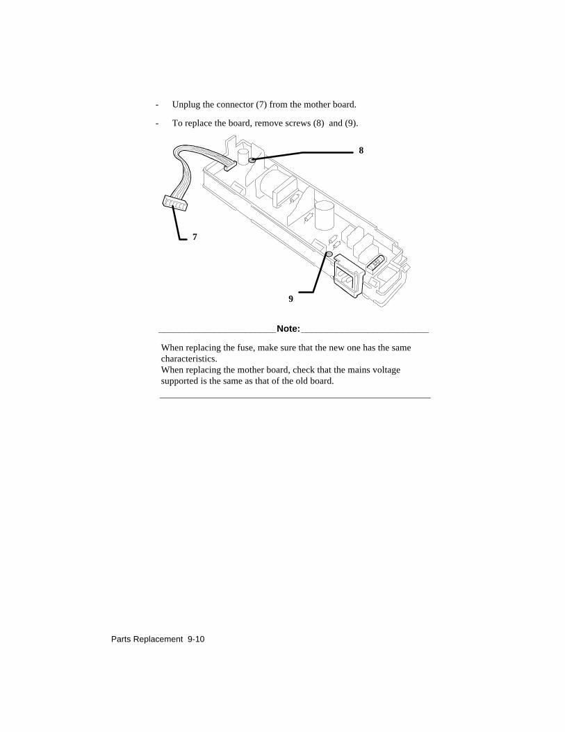
Parts Replacement 9-10
- Unplug the connector (7) from the mother board.
- To replace the board, remove screws (8) and (9).
_______________________Note:_________________________
When replacing the fuse, make sure that the new one has the samecharacteristics.When replacing the mother board, check that the mains voltagesupported is the same as that of the old board.
8
7
9

Parts Replacement 9-11
9.8 DISASSEMBLING / RE-ASSEMBLING THE PAPERFEED MOTOR
- Remove the power supply board (section 9.7)
- Unhook and take out the separator (1)
- Remove screws (2) and (3) and withdraw the paper feed motor (A)
- Free the motor cables from the cable clamp slots and unplug theconnector from the mother board.
_______________________Note:_________________________
After reassembling the motor, calibrate the paper feed motor belttension as described in section 8.2.
1A
2
3

Parts Replacement 9-12
9.9 DISASSEMBLING / RE-ASSEMBLING THECARRIAGE MOTOR
- Remove the mother board (section 9.5)
- Lift tab (A) and draw out the ground spring (1)
- Unclasp hook (2) that fastens the bottom, then remove themotor from its housing
_______________________Note:_________________________
When re-assembling, make sure that the belt and belt tensioned arefunctioning correctly
1
2
A
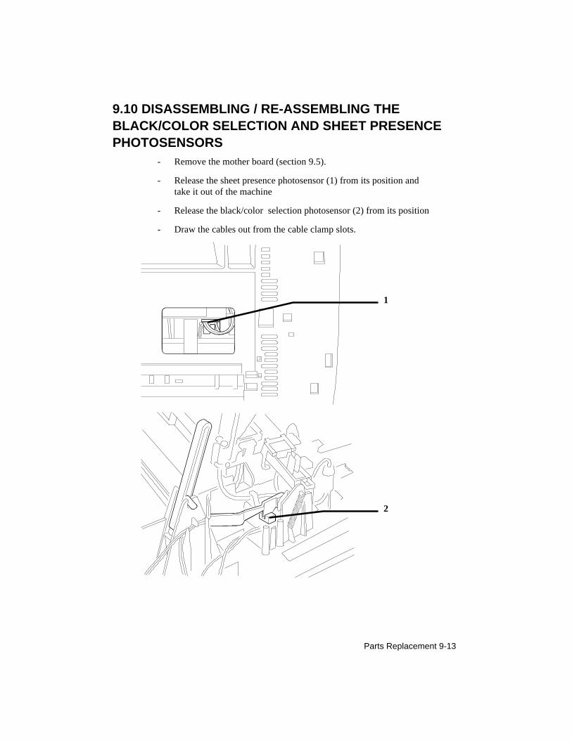
Parts Replacement 9-13
9.10 DISASSEMBLING / RE-ASSEMBLING THEBLACK/COLOR SELECTION AND SHEET PRESENCEPHOTOSENSORS
- Remove the mother board (section 9.5).
- Release the sheet presence photosensor (1) from its position andtake it out of the machine
- Release the black/color selection photosensor (2) from its position
- Draw the cables out from the cable clamp slots.
1
2

Parts Replacement 9-14
9.11 DISASSEMBLING / RE-ASSEMBLING THE LINEARENCODER
- Remove the mother board (section 9.5)
- Take out the tensioning leaf spring (1) and turning it 900, free itfrom the linear encoder strip
- Free the encoder band from the fastening hook at the other endand carefully withdraw it from the reading slot on the print head.
_______________________Note:_________________________
When re-assembling the strip, make sure that it is positioned so thatthe arrows are pointing upwards and that the written indications can beread correctly(see figure below), and take care to insert it correctly inthe print head photosensor slot.
DO NOT TOUCH THE SHADED AREA ON THE STRIP, OTHERWISETHE PHOTOSENSOR MAY NOT READ THE SIGNALS CORRECTLY.
1

Parts Replacement 9-15
9.12 DISASSEMBLING / RE-ASSEMBLING THE PRINTCARRIAGE
- Remove the carriage motor (section 9.9)
- Remove the linear encoder (section 9.11)
- Withdraw the carriage upper guide shaft (1)
- Remove the flexible supporting brackets and withdraw thecarriage lower guide shaft (2)
- Draw out the flat cables (3) from the guides on the paperoutfeed group and remove the carriage from the machine
_______________________Note:_________________________
After re-assembling, run a print test and, if necessary, adjust thedistance between print head nozzles and writing surface as describedin section 8.1.
1
3
2

Parts Replacement 9-16
9.13 DISASSEMBLING / RE-ASSEMBLING THE PAPEROUTFEED GROUP
- Remove the casing (section 9.4)
- Withdraw the head flat cable from the guides on the paper outfeed group
- Free the ends of the ink tube
- Release the paper outfeed group from clasps (1), (2), (3), (4) and raise it.
_______________________Note:_________________________
When re-assembling, take care to insert the tractor group correctly.
1
2
4
3