Decoupling of multiple antennas in terminals with chassis ...
11
Decoupling of multiple antennas in terminals with chassis excitation using polarization diversity, angle diversity and current control Li, Hui; Lau, Buon Kiong; Ying, Zhinong; He, Sailing Published in: IEEE Transactions on Antennas and Propagation 2012 Document Version: Peer reviewed version (aka post-print) Link to publication Citation for published version (APA): Li, H., Lau, B. K., Ying, Z., & He, S. (2012). Decoupling of multiple antennas in terminals with chassis excitation using polarization diversity, angle diversity and current control. IEEE Transactions on Antennas and Propagation, 60(12), 5947-5957. Total number of authors: 4 General rights Unless other specific re-use rights are stated the following general rights apply: Copyright and moral rights for the publications made accessible in the public portal are retained by the authors and/or other copyright owners and it is a condition of accessing publications that users recognise and abide by the legal requirements associated with these rights. • Users may download and print one copy of any publication from the public portal for the purpose of private study or research. • You may not further distribute the material or use it for any profit-making activity or commercial gain • You may freely distribute the URL identifying the publication in the public portal Read more about Creative commons licenses: https://creativecommons.org/licenses/ Take down policy If you believe that this document breaches copyright please contact us providing details, and we will remove access to the work immediately and investigate your claim.
Transcript of Decoupling of multiple antennas in terminals with chassis ...
LUND UNIVERSITY
PO Box 117221 00 Lund+46 46-222 00 00
Decoupling of multiple antennas in terminals with chassis excitation using polarizationdiversity, angle diversity and current control
Li, Hui; Lau, Buon Kiong; Ying, Zhinong; He, Sailing
Published in:IEEE Transactions on Antennas and Propagation
2012
Document Version:Peer reviewed version (aka post-print)
Link to publication
Citation for published version (APA):Li, H., Lau, B. K., Ying, Z., & He, S. (2012). Decoupling of multiple antennas in terminals with chassis excitationusing polarization diversity, angle diversity and current control. IEEE Transactions on Antennas andPropagation, 60(12), 5947-5957.
Total number of authors:4
General rightsUnless other specific re-use rights are stated the following general rights apply:Copyright and moral rights for the publications made accessible in the public portal are retained by the authorsand/or other copyright owners and it is a condition of accessing publications that users recognise and abide by thelegal requirements associated with these rights. • Users may download and print one copy of any publication from the public portal for the purpose of private studyor research. • You may not further distribute the material or use it for any profit-making activity or commercial gain • You may freely distribute the URL identifying the publication in the public portal
Read more about Creative commons licenses: https://creativecommons.org/licenses/Take down policyIf you believe that this document breaches copyright please contact us providing details, and we will removeaccess to the work immediately and investigate your claim.

1
Abstract—Excitation of the chassis enables single-antenna
terminals to achieve good bandwidth and radiation performance,
due to the entire chassis being utilized as the main radiator. In
contrast, the same chassis excitation phenomenon complicates the
design of multiple antennas for MIMO applications, since the same
characteristic mode of the chassis may be effectively excited by
more than one antenna, leading to strong mutual coupling and
severe MIMO performance degradation. In this paper, we
introduce a design concept for MIMO antennas to mitigate the
chassis-induced mutual coupling, which is especially relevant for
frequency bands below 1 GHz. We illustrate the design concept on
a dual-antenna terminal at 0.93 GHz, where a folded monopole at
one chassis edge excites the chassis’ fundamental electric dipole
mode and a coupled loop at the other chassis edge excites its own
fundamental magnetic dipole mode. Since the two radiation modes
are nearly orthogonal to each other, an isolation of over 30 dB is
achieved. Moreover, we show that the antenna system can be
conveniently modified for multiband operation, such as in the
900/1800/2600 MHz bands. Furthermore, by controlling the phase
of the feed current on the folded monopole, the two antennas can
be co-located on the same chassis edge with an isolation of over 20
dB. The co-located dual antenna prototype was fabricated and
verified in the measurements.
Index Terms— Antenna array, mutual coupling, MIMO
systems, mobile communication.
I. INTRODUCTION
igh transmission rates of next generation communication
systems require significant attention on antenna design [1].
Implementing multiple antennas in both base stations and
terminals is a key solution to increase channel capacity without
Manuscript received November 11, 2011. This work was supported in part
by VINNOVA under grant no. 2009-04047 and 2008-00970, and also in part
by a scholarship within EU Erasmus Mundus External Cooperation Window
Lot 14.This paper was presented in part at the XXX URSI General Assembly
and Scientific Symposium, Istanbul, Turkey, Aug 13-20, 2011, and submitted
in part as a patent application with Sony Ericsson Mobile Communication AB.
H. Li and S. He are with the School of Electromagnetic Engineering, Royal
Institute of Technology, SE-100 44 Stockholm, Sweden (e-mail: {huili, sailing}
@ee.kth.se). They are also with the Center for Optical and Electromagnetic
Research, Zhejiang University, Hangzhou, 310058, China.
B. K. Lau is with the Department of Electrical and Information Technology,
Lund University, 221 00 Lund, Sweden (e-mail: [email protected]. se).
Z. Ying is with Research and Technology, Corporate Technology Office,
Sony Ericsson Mobile Communications AB, 221 88 Lund, Sweden (e-mail:
sacrificing additional frequency spectrum and transmit power.
In reality, the compactness of today’s terminals complicates the
design of multiple antennas, since it results in strong mutual
coupling and degradation in the expected performance of the
antennas, such as bandwidth, efficiency and channel capacity
[2]-[5].
Most of the existing coupling reduction techniques suitable
for mobile terminals focus on relatively high frequency bands,
including WLAN, DCS1800 and UMTS bands [6]-[10], even
though in practice the problem of coupling is more severe at
lower frequencies. Existing literature shows that the isolation of
multiple antennas in compact terminals is typically less than 6
dB for frequencies below 1 GHz (see e.g., [11]). According to
[12], decoupling at low frequency bands is challenging, because
the chassis does not only function as a ground plane, but also as
a radiator shared by the multiple antennas. Thus, the radiation
patterns are strongly influenced by the shared chassis, such that
angle and polarization diversities are difficult to achieve among
the antennas for the purpose of decoupling. To avoid the
excitation of the shared chassis by more than one antenna in a
two-antenna setup, the position of the second antenna can be
optimized to effectively reduce the chassis excitation [12]. In
particular, the isolation is enhanced from below 4 dB to 10 dB,
as the second antenna is moved from the edge of the chassis
towards the center position, and the first antenna is kept at the
other edge of the chassis. However, this technique is aimed at
mitigating chassis excitation and does not create much angle
and polarization diversities, which puts a limit on the achievable
isolation. Furthermore, it is often impractical to place an
antenna at the center of the chassis, considering the common
layout of device components on the printed circuit board (PCB).
In this paper, based on the characteristic mode analysis in
[12], a new concept is proposed to effectively mitigate coupling,
especially chassis-induced coupling, among MIMO antennas.
Instead of moving the second antenna from the chassis edge to
the chassis center as in [12], we replaced the antenna at the
chassis edge with a magnetic antenna to circumvent coupling
with the first antenna, which intentionally excites the chassis. In
this manner, we achieve both polarization and angle diversities.
The concept is first demonstrated through an ideal flat dipole
and a small loop. As one practical realization of the concept, we
introduced a dual-antenna structure at 0.93 GHz, which consists
of a folded monopole and a coupled feed loop on opposite edges
of a chassis. The monopole excites the chassis, and radiates like
Decoupling of Multiple Antennas in Terminals
with Chassis Excitation Using Polarization
Diversity, Angle Diversity and Current Control
Hui Li, Student Member, IEEE, Buon Kiong Lau, Senior Member, IEEE, Zhinong Ying, Senior Member,
IEEE, and Sailing He, Senior Member, IEEE
H

2
a flat electric dipole. The coupled loop avoids exciting the
chassis by radiating like a magnetic dipole at the point where the
characteristic mode of chassis has the least magnetic field
component. This approach effectively mitigates the chassis
induced coupling and produces near-orthogonal radiation
patterns, leading to both high isolation and high total antenna
efficiencies. It should be noted that perfect orthogonal radiation
patterns are only achieved by an infinitesimal dipole and an
infinitesimal loop, since these ideal antenna patterns are
orthogonally polarized. This phenomenon can also be
understood in that, in the near field region, an infinitesimal
dipole radiates pure electric field, whereas an infinitesimal loop
yields pure magnetic field. Furthermore, the antenna design in
this paper is based on the typical candybar-type mobile chassis,
with the size of 100 mm × 40 mm. One can easily apply the
proposed design principle by appropriate scaling to smart
phones (e.g., 125 mm × 65 mm) for the 700 MHz LTE band.
Alternatively, a larger bandwidth can be achieved with a larger
chassis at the same operating frequency of 0.93 GHz.
The paper is organized as follows: In Section II, the radiation
properties of a lossless dual-antenna structure (with an electric
dipole and a small loop) are carefully analyzed in the context of
applying the theory of characteristic mode to compact
dual-antenna design. The design principle is then applied in
Section III to obtain an efficient two-antenna solution for a
compact chassis at 0.93 GHz. A varactor diode is applied to the
coupled loop to tune its frequency and cover a larger bandwidth
from 780 MHz to 980 MHz. Moreover, to establish multiband
capability, we showed that the dual-antenna system can be
slightly modified to operate in three bands, including the 900
MHz, 1.8 GHz and 2.6 GHz bands. Section IV demonstrates
how the two antennas can be re-designed to be co-located on the
same edge of the chassis, which greatly reduces the
implementation space. A prototype of the co-located antenna
system was fabricated, and the measured results are presented in
Section V. Section VI concludes the paper.
II. ELECTRIC AND MAGNETIC DIPOLE ANTENNAS
Since the proposed design concept in this paper is based on
exploiting the radiation characteristics of electric and magnetic
dipole antennas, we begin by showing how these simple antenna
structures are relevant to compact terminal applications, where
all antenna elements are implemented on a small chassis.
In essence, a flat electric dipole antenna can be formed by
appropriately exciting the entire chassis with an antenna
element [13]. To illustrate the mechanism of chassis excitation,
we used the theory of characteristic mode [14] to calculate the
characteristic electric and magnetic fields of the chassis. For a
100 mm × 40 mm chassis, the normalized characteristic electric
and magnetic fields on a plane 5 mm above the chassis at the
first characteristic frequency (1.35 GHz) are shown in Figs. 1(a)
and 1(b), respectively. Here, the chassis is modeled by a perfect
conducting board. Fig. 1(a) reveals that, in order to strongly
excite the first characteristic mode of the chassis, the antenna
element should store electric energy in the near field (henceforth
called ‘electric antenna’) and be placed at either of the two
shorter edges of the chassis. Therefore, if two electric antennas
are placed at the two chassis edges, both antennas will share the
chassis as their radiator, causing severe mutual coupling.
On the contrary, according to Fig. 1(b), if an antenna at a
shorter edge stores mainly magnetic energy but little electric
energy (henceforth called ‘magnetic antenna’) in the near field,
the antenna is unable to excite the chassis. This implies that if an
electric antenna is used at the other edge to excite the chassis,
the magnetic antenna will be unaffected by the chassis
excitation, resulting in high isolation.
(a)
(b)
Fig. 1. The normalized magnitude of (a) the total electric field and (b) the total
magnetic field for the characteristic mode of the chassis at 1.35 GHz.
To study the coupling performance of such an ideal
dual-antenna setup, with an electric antenna perfectly exciting
the chassis and a magnetic antenna avoiding chassis excitation,
we utilized the equivalent dual-antenna structure in Fig. 2(a).
Detailed geometries of the antenna structure are provided in Fig.
2(a). As can be seen, the whole structure retains the original
chassis size of 100 mm × 40 mm. The dual antenna system
consists of a flat dipole and a small loop, where the flat dipole
models the excited chassis, and the small loop works as a
magnetic antenna.
To realize the magnetic antenna with the small loop, we set
the radius of the small loop to be 6.5 mm, corresponding to
0.018λ at 0.9 GHz. This ensures almost uniform in-phase

3
current distribution along the perimeter of the loop. The flat
dipole is excited by a voltage applied at its normal feed point.
Both antennas are assumed to be perfect electric conductors
(PECs) and they are printed on a lossless substrate with the
dielectric permittivity of 2.45 and the thickness of 0.8 mm.
Full-wave antenna simulations were carried out in the
frequency domain using CST Microwave Studio. Both the flat
dipole and the small loop resonate at 0.9 GHz, as shown by the
scattering (or S) parameters in Fig. 2(b). Ideal single-stub
matching networks [15] are used to ensure good impedance
matching at the center frequency (with S11 < -20 dB). The total
efficiencies of both antennas are 99% at 0.9 GHz, since the
whole antenna system is assumed to be lossless. The isolation is
above 25 dB, despite their close proximity to each other.
L
W1
R
r
L1antenna 1(port 1):
flat dipole
antenna 2 (port 2):
Small loop
X
Y
(a)
Z
Fig. 2. (a) The geometries of the flat dipole and the small loop. The dimensions
are: L = 100 mm, W1= 40 mm, r = 6 mm, R = 7 mm, L1 = 15 mm. (b) The S
parameters of the ideal flat dipole and the small loop.
The E-theta and E-phi components of the normalized
far-field antenna patterns at 0.9 GHz are presented in Fig. 3. The
pattern of each antenna was obtained with the other antenna
terminated in 50 . Several observations can be made from the
figure. Firstly, the flat dipole has a linearly polarized “donut”
radiation pattern, which is similar to that of a conventional half
wavelength dipole oriented along the y axis. Secondly, the small
loop has the same “donut” radiation pattern as the magnetic
dipole, with the peak gain along the plane of the loop and the
E-phi component being 20 dB larger than the E-theta
component. Comparing the E-phi components in Figs. 3(a) and
3(c) and the E-theta components in Figs. 3(b) and 3(d), it can be
seen that the two patterns are orthogonal in polarization, with
the exception of a small overlap in the E-phi components.
Besides, angle diversity is achieved across the two antennas,
since the directions of the peak gains are mostly complementary
to each other. Therefore, the mutual coupling between the two
ideal antennas is weak (S21 < -25 dB), despite the small
center-to-center antenna separation of less than 0.15. Indeed,
the pattern orthogonality of such a co-polarized dipole-loop
antenna arrangement has been experimentally demonstrated in
[16], though for the special case of co-located phase centers.
(b) flat dipole, E-theta
(d) small loop, E-theta(c) small loop, E-phi
(a) flat dipole, E-phi
0-20 dB
-0.1-20 dB
-20-40 dB
Phi Phi
Phi Phi
Theta
0
60
120
180
0 60 120 180 240 300 360
Theta
0
60
120
180
0 60 120 180 240 300 360
Theta
0
60
120
180
0 60 120 180 240 300 360
Theta
0
60
120
180
0 60 120 180 240 300 360
-0.2 dB-20
Fig. 3. The far-field radiation patterns for the flat dipole and the small loop at
0.9 GHz, normalized to the maximum field over both antennas.
In practice, however, the small loop in Fig. 2(a) cannot be
directly used due to its small radiation resistance Rr of 0.045 ,
which is calculated using the expression [17]
4
220r
CR
, (1)
where C = 2πa is the circumference of the loop with radius a.
The radiation efficiency of an antenna is determined by its
radiation and loss resistances [17]. In general, the loss resistance
of a single turn loop is much larger than its radiation resistance;
thus the corresponding radiation efficiency is very low (< 10%).
The ideal antenna study above assumes lossless material to
ensure that the loop radiates efficiently. However, lossless
material does not exist in reality. In addition, electrically small
antennas also suffer from high Q factor and narrow bandwidth,
as is evident in Fig. 2(b). The required matching network also
complicates the design of the antennas system and introduces
additional loss in reality. Thus, an efficient magnetic antenna
with a much larger radiation resistance is desired. A normal way
to increase the radiation resistance of the loop is to employ an
N-turn loop, which unfortunately is difficult to implement on a
planar PCB. In 2007, Erentok and Ziolkowski introduced a
coupled feeding method for the loop, based on the idea of split
ring resonator (SRR). The method effectively reduces the
antenna dimension and increases the total efficiency [18], [19].
A more sophisticated 3D version was later proposed in [20]. In
this paper, based on the antenna structure in [19], a planar
coupled feed loop is employed to realize the magnetic antenna.
It is noted that the electric antenna at the chassis edge, which
is used to excite the chassis, can also be moved to the center of
the chassis. This alternative setup will still offer good isolation.

4
However, in this case, the chassis will function as a normal
ground plane of the electric antenna and can no longer be
efficiently excited as the radiator [12]. Since chassis excitation
helps to increase the bandwidth (of the electric antenna) [21],
such a strategy of avoiding chassis excitation is less desirable
when considering performance in terms of both bandwidth and
isolation. As for the magnetic antenna, since it is designed to not
excite the chassis in order to achieve decoupling, its bandwidth
is expected to be narrower than those of conventional terminal
antennas, such as PIFAs and monopoles. Hence, in this paper,
we focus on the case that an electric antenna is used to exploit
chassis excitation in order to ensure a larger bandwidth, and a
magnetic antenna is used to achieve good isolation in the
presence of chassis excitation. Frequency reconfiguration will
be applied to compensate the bandwidth limitation of the
magnetic antenna in Section III-B.
III. DUAL-ANTENNA SYSTEM AT A LOW FREQUENCY BAND
A. Antenna Geometries and Performance
Based on the discussions in the previous section, a practical
terminal antenna system consisting of a folded monopole (i.e.,
an “electric antenna”) and a coupled feed small loop (i.e., a
“magnetic antenna”) is proposed. Folded monopoles are
commonly used in mobile phones, due to their simplicity and
good performance. The geometries of the antenna system are
presented in Fig. 4(a). For ease of fabrication, the folded
monopole and the coupled loop were printed on a thin copper
layer above a substrate. The conductivity and thickness of the
copper layer are 5.8×10⁷ S/m and 35 m, respectively. The
substrate has a permittivity of 2.45, a loss tangent of 0.003 and a
thickness of 0.8 mm. The monopole is fed by a microstrip line.
As observed from Fig. 4(a), the coupled feed small loop
consists of two half square rings, with the inner ring acting as the
matching feed and the outer ring as the main radiator. The inner
ring is an impedance transformer, which transforms the port
impedance (50 ) to the impedance of the outer loop. The outer
half ring takes advantage of the shorter edge of the chassis to
form a full ring, forming an efficient radiator. The simulated
input resistance is around 42 at the resonant frequency, which
is almost a thousand-fold increase relative to that of the small
loop in Fig. 2(a). Thus, high radiation efficiency is expected.
The inter-digital capacitor, with both the arm width and
inter-arm separation of 0.8 mm, is used to capacitively load the
loop. The resonant frequency of the coupled loop can be tuned
by the length of the arms (Lc) and the inter-arm separation.
It is noted that the feeding structure of the coupled loop is not
limited to the half square ring. It can also be an inverted L-shape
feed or a T-shape feed (see Figs. 4(b) and 4(c)), as long as it is
an efficient impedance transformer to match the loop well.
The simulated S parameters of the dual-antenna system are
shown in Fig. 5. It is observed that both the monopole and the
coupled loop are well-matched, and the isolation is above 30 dB,
which is very high for frequency bands below 1 GHz. Here, we
note that the focus of this paper is on the new decoupling
mechanism and its application on multiple antennas at low
frequency bands. Therefore, we make no explicit effort to
enlarge the bandwidth of the folded monopole.
L
W1
h 2
L1
Wm
d
X
Y
Z
Antenna 1: folded
monopole
W3
W2
Lc
L2
Antenna 2:
coupled loop
(outer loop)
(b)
(c)(a)
feeding loop
Fig. 4. (a) The geometries of the folded monopole and the coupled feed loop.
The dimensions are: L = 100 mm, W1 = 40 mm, L1 = 15 mm, L2 = 10 mm, h2 =
6 mm, Lc = 7.5 mm, W3= 2 mm, W2 = 3 mm, Wm = 1 mm, d = 12 mm. (b)
Coupled loop with inverted L-shape feed. (c) Coupled loop with T-shape feed.
Fig. 5. The S parameters of the folded monopole and the coupled feed loop.
The total efficiency of an antenna (“antenna 1”) in a
two-antenna setup is given by total= rad (1 – |S11|2 – |S21|2). Due
to the high radiation efficiency rad, good matching (|S11|, |S22| <
-15 dB) and low mutual coupling (|S21|, |S12| < -30 dB), the total
efficiencies of both the monopole and the loop are very high,
i.e., 92% and 80%, respectively, at 0.93 GHz.
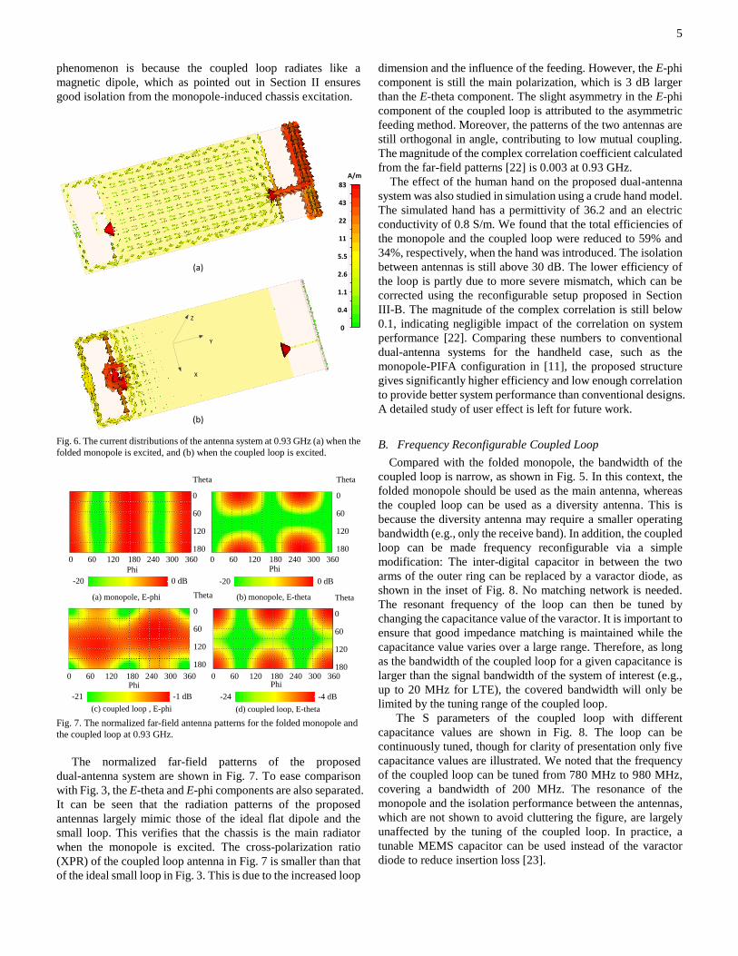
In Fig. 6, the current distributions of the proposed antenna
system are presented. As expected, Fig. 6(a) shows the strong
chassis excitation by the monopole. From Fig. 6(b), it is
observed that the current in the coupled loop (i.e., the outer
loop) is almost constant when the loop is excited. Although the
coupled loop makes use of the shorter edge of the chassis, the
characteristic mode of the chassis is not excited. This
5
phenomenon is because the coupled loop radiates like a
magnetic dipole, which as pointed out in Section II ensures
good isolation from the monopole-induced chassis excitation.
X
Y
Z
(a)
(b)
A/m83
43
22
11
5.5
2.6
1.1
0.4
0
Fig. 6. The current distributions of the antenna system at 0.93 GHz (a) when the
folded monopole is excited, and (b) when the coupled loop is excited.
-21 -1 dB -24 -4 dB
-20 0 dB-20 0 dB
(a) monopole, E-phi (b) monopole, E-theta
(c) coupled loop , E-phi (d) coupled loop, E-theta
Phi Phi
Phi
Theta
0
60
120
1800 60 120 180 240 300 360
Theta
0
60
120
180
0 60 120 180 240 300 360
Theta
0
60
120
180
0 60 120 180 240 300 360
Theta
0
60
120
180
0 60 120 180 240 300 360Phi
Fig. 7. The normalized far-field antenna patterns for the folded monopole and
the coupled loop at 0.93 GHz.
The normalized far-field patterns of the proposed
dual-antenna system are shown in Fig. 7. To ease comparison
with Fig. 3, the E-theta and E-phi components are also separated.
It can be seen that the radiation patterns of the proposed
antennas largely mimic those of the ideal flat dipole and the
small loop. This verifies that the chassis is the main radiator
when the monopole is excited. The cross-polarization ratio
(XPR) of the coupled loop antenna in Fig. 7 is smaller than that
of the ideal small loop in Fig. 3. This is due to the increased loop
dimension and the influence of the feeding. However, the E-phi
component is still the main polarization, which is 3 dB larger
than the E-theta component. The slight asymmetry in the E-phi
component of the coupled loop is attributed to the asymmetric
feeding method. Moreover, the patterns of the two antennas are
still orthogonal in angle, contributing to low mutual coupling.
The magnitude of the complex correlation coefficient calculated
from the far-field patterns [22] is 0.003 at 0.93 GHz.
The effect of the human hand on the proposed dual-antenna
system was also studied in simulation using a crude hand model.
The simulated hand has a permittivity of 36.2 and an electric
conductivity of 0.8 S/m. We found that the total efficiencies of
the monopole and the coupled loop were reduced to 59% and
34%, respectively, when the hand was introduced. The isolation
between antennas is still above 30 dB. The lower efficiency of
the loop is partly due to more severe mismatch, which can be
corrected using the reconfigurable setup proposed in Section
III-B. The magnitude of the complex correlation is still below
0.1, indicating negligible impact of the correlation on system
performance [22]. Comparing these numbers to conventional
dual-antenna systems for the handheld case, such as the
monopole-PIFA configuration in [11], the proposed structure
gives significantly higher efficiency and low enough correlation
to provide better system performance than conventional designs.
A detailed study of user effect is left for future work.
B. Frequency Reconfigurable Coupled Loop
Compared with the folded monopole, the bandwidth of the
coupled loop is narrow, as shown in Fig. 5. In this context, the
folded monopole should be used as the main antenna, whereas
the coupled loop can be used as a diversity antenna. This is
because the diversity antenna may require a smaller operating
bandwidth (e.g., only the receive band). In addition, the coupled
loop can be made frequency reconfigurable via a simple
modification: The inter-digital capacitor in between the two
arms of the outer ring can be replaced by a varactor diode, as
shown in the inset of Fig. 8. No matching network is needed.
The resonant frequency of the loop can then be tuned by
changing the capacitance value of the varactor. It is important to
ensure that good impedance matching is maintained while the
capacitance value varies over a large range. Therefore, as long
as the bandwidth of the coupled loop for a given capacitance is
larger than the signal bandwidth of the system of interest (e.g.,
up to 20 MHz for LTE), the covered bandwidth will only be
limited by the tuning range of the coupled loop.
The S parameters of the coupled loop with different
capacitance values are shown in Fig. 8. The loop can be
continuously tuned, though for clarity of presentation only five
capacitance values are illustrated. We noted that the frequency
of the coupled loop can be tuned from 780 MHz to 980 MHz,
covering a bandwidth of 200 MHz. The resonance of the
monopole and the isolation performance between the antennas,
which are not shown to avoid cluttering the figure, are largely
unaffected by the tuning of the coupled loop. In practice, a
tunable MEMS capacitor can be used instead of the varactor
diode to reduce insertion loss [23].

6
Fig. 8. The S parameters of the coupled loop, with different values of
capacitance in between the two arms of the outer ring.
C. Switchable Tri-band Dual Antenna System
In this sub-section, the dual antenna system is designed
practically to work in three bands, including the GSM900,
GSM1800 and LTE2600 bands. The geometries of the dual-
antenna system are presented in Fig. 9. In this case, the coupled
loop is implemented on a hollow carrier made of plastic, which
demonstrates the flexibility of the antenna structure to account
for mobile phone integration. For example, a speaker and/or a
camera can be placed inside the hollow carrier to facilitate
better integration and conserve space.
The multi-resonance of the folded monopole is easy to create
and tune by adding a short branch (Lm2) near its open end. For
the coupled feed loop, three main modifications are needed to
achieve multi-resonance. First, a switch is added to each of the
outer ring and the inner ring, to switch the resonance(s) of the
loop between the low band and the two higher bands. Second, a
new branch (L3) is added to the original structure to create high
frequency resonances. Besides, the inner ring (feeding loop) is
also modified in order to function as an efficient impedance
transformer at the two high bands. When the two switches are on
(short circuit), the structure of the loop is similar as that of the
original loop in Section III-A, and it resonates at 0.93GHz.
When the two switches are off (open circuit), the antenna
radiates like a monopole. The lengths for the two different
electrical paths of the antenna correspond to the frequency
bands of 1.8 GHz and 2.6 GHz, respectively. The S parameters
at the low band and the two higher bands of the dual antenna
system are presented in Fig. 9(b) and 9(c), respectively. It can
be seen that, through utilizing two switches, the three operating
bands are fully covered by the dual antenna system, with an
isolation of above 15 dB. The impedance matching at the higher
frequency bands is mainly influenced by the width of the gap in
the coupled feed (W7), the length of the coupled feed (L2) and
the distance between the two antenna branches (d1). When
tuning these parameters, there is a trade-off between the
impedance matching at 1.8 GHz and 2.6 GHz. Since the tri-band
antenna system only serves to demonstrate the multiband
potential of the proposed antenna as a practical consideration,
and for the sake of conciseness, its working mechanisms and
parameter analysis are not explained in detail here.
L1
W1
h1
d
h2
Lm
1
Lm
2
Wm
W5
L3
W5
W5
W4
L2
W2
W3
W6W7
L4
Switch 2
Switch 1
X
Y
Z
d1
(a)
Fig. 9. (a) The geometries of the tri-band dual-antenna system. The
dimensions are: L1 = 17 mm, W1 = 40 mm, L2 = 14 mm, W2 = 5 mm, W3 = 2
mm, W4 = 17mm, W5 = 17 mm, W6 = 0.5mm,W7 = 0.3mm, L3 = 22 mm, L4 =
1.5 mm, h1 = 6 mm, h2 = 6 mm, d1 = 5 mm, d = 12 mm, Lm1 = 10 mm, Wm = 1
mm, Lm2 = 5 mm. (b) The S parameters of the tri-band dual-antenna system at
the low band, with switches on. (c) The S parameters at the higher bands, with
switches off.

7
IV. CO-LOCATED MOBILE ANTENNAS
A. Decoupling Technique in Co-located Mobile Antennas
To reduce the space for antenna implementation on the
chassis, the folded monopole and the coupled loop can be
co-located on the same edge of the chassis, as presented in Fig.
10. The geometries of both antennas need to be slightly changed
to ensure good impedance matching. However, achieving good
isolation for this antenna setup is more challenging than in the
previous case in Section III-A. This is because the feed points of
the two antennas are very close to each other, and thus in general
the coupling between the feeds results in a direct current path
between the antennas, which degrades isolation.
Feeding
strip for
monopole
Feed for
loop
Fig. 10. The geometries of co-located dual-antenna system. The dimensions are:
L1 = 17 mm, W1 = 40 mm, L2 = 15 mm, W2 = 7 mm, W3 = 2 mm, h1 = 6 mm, h2
= 6 mm, Lc = 9.85 mm, d = 18.5 mm, Lm = 14.5 mm, Wm = 1 mm.
A/m
77.8
58.1
32.3
24
18
10
6
3.6
1.7
1
0.6
0
Feeding strip
Fig. 11. The current distribution of the excited single folded monopole at the
resonant frequency.
To solve the problem of coupling due to feed proximity, a
single folded monopole antenna was studied first. The current
distribution of the excited single folded monopole is presented
in Fig. 11. It can be seen that the currents along the feeding strip
are in phase when the monopole and the chassis are efficiently
excited. To decouple the antennas in the dual-antenna case, we
require the opposite situation of the currents along the feeding
strip of monopole being out of phase when the coupled loop is
excited. The near fields of the out-of-phase currents will then
cancel one another and thus the monopole cannot be efficiently
excited. The phases of the currents along the feeding strip are
related to the electrical length of the current paths between the
two feeds. Therefore, the coupling between the feeds critically
depends on two parameters, namely, the length of the feeding of
the small loop (L2) and the location of the feeding strip of the
folded monopole (d). However, any variation in L2 will
complicate the antenna design due to its strong influence on the
impedance matching of the coupled loop. If L2 is changed, other
parameters, such as W3 and Lc, need to be changed accordingly
to ensure good impedance matching. Consequently, it is more
convenient to optimize the location of the monopole’s feeding
strip in order to decouple the co-located antennas.
A/m
273
131
40
21
10
1.5
0
-3
-15
-29
-54
-176
-273
(b) (c)
Fig. 12. (a)The S parameters of the coupled loop, with different values of d. (b)
the current distribution with d = 20 mm when the coupled loop is excited. (c)
the current distribution with d = 18.5 mm when the coupled loop is excited.
The S parameters of the folded monopole and the coupled
loop for three different values of d are presented in Fig. 12(a).
From the figure, it is observed that when d = 18.5 mm, the
isolation is over 20 dB for the whole operating band. However,
in the other two cases, the isolations are below 10 dB. It is
interesting to note that when the value of d changes, the
frequency of the local coupling null (the minimum point of the
“valley” in S21) varies accordingly. This is explained as follows:
The variation of d changes the physical length of the current
path from the excited loop to the feeding strip of the monopole.
Each physical length corresponds to different electrical lengths
for the same frequency. There is one electric length satisfying
the condition that the currents along the feeding strip are out of
phase. The corresponding frequency is then the coupling null.
For different physical lengths, the coupling null frequency will
also be different. The isolation decreases as the frequencies
depart from the frequency of the coupling null, thus forming the

8
shape of a valley. Figures 12(b) and 12(c) show the current
distributions at 0.93 GHz for d = 20 mm and d = 18.5 mm,
respectively, with only the loop excited. In Fig. 12(b), when d =
20 mm, the currents on the feeding strip of monopole are in
phase. Therefore, the monopole is excited, and the coupling is
severe. However, when d = 18.5 mm, the currents in Fig. 12(c)
are out of phase on the feeding strip, forming a coupling null. In
the optimization, the resonant frequencies of the two antennas
and the frequency of the coupling null can be aligned. For ease
of design, it is important that these frequencies can be tuned
independently of one another. Indeed, these frequencies largely
depend on the length of the monopole (Lm), the capacitance
between the arms of the loop (Lc) and the location of the feeding
strip (d), respectively. The decoupling method outlined above
can also be applied to other multiple antenna systems, where the
mutual coupling is caused by the proximity of the antenna feeds.
The total efficiencies when d = 18.5 mm are 80% and 76% for
the folded monopole and the coupled loop, respectively. The
total efficiencies of the co-located antennas are lower than
antennas in Fig. 4(a), which is mainly the result of using the
lossy hollow carrier, although poorer isolation is also a
contributing factor.
B. MIMO Performance of the Co-located Mobile Antennas
Diversity gain and MIMO capacity are the most popular
metrics for evaluating the performance of multiple antenna
systems. Since the two metrics show similar trends, only
capacity is presented in this paper. The capacity is calculated for
different frequencies under the waterfilling (WF) condition [24]
for a reference SNR of 20 dB. The WF procedure is performed
over the antenna elements at each frequency. The Kronecker
model [25] and uniform 3D angular power spectrum (APS) are
assumed. There is no correlation between the (base station)
transmit antennas, whereas the (terminal) receive antennas are
correlated according to their patterns and the uniform 3D APS.
The capacity is averaged over 10,000 identical and
independently distributed (IID) Rayleigh realizations [24] at
each frequency. The channels are normalized with respect to the
IID Rayleigh case, which means that the correlation, total
efficiency and efficiency imbalance are taken into account in the
capacity evaluation.
The channel capacity for three cases are presented in Fig. 13,
i.e., the IID Rayleigh channel, the proposed co-located
dual-antenna system in uniform 3D APS, and a reference
dual-antenna system in uniform 3D APS. The reference system
is a typical monopole-and-PIFA configuration, with the two
antennas located separately on the two shorter edges of the
chassis [12]. The IID case corresponds to the ideal situation of
100% total antenna efficiencies and zero correlation between
the antennas. The center frequency of the dual-antenna systems
is 0.93 GHz. A bandwidth of 20 MHz is chosen because it
covers the downlink bandwidth of a single LTE channel. From
the figure, it is concluded that the proposed co-located antenna
system not only saves implementation space on the PCB, but
also increases the channel capacity by more than 2 bits/s/Hz,
when compared to a typical dual-antenna design. If the two
antennas are not co-located, as in Fig. 4, the channel capacity
will further increase due to higher total antenna efficiencies.
Fig. 13. Channel capacities for three different cases.
Fig. 14. Multiplexing efficiencies of the proposed and reference dual-antenna
systems. ηmux and ηg for the proposed system almost overlap with each other.
In order to provide intuitive insights into the relative impact
of different non-ideal effects of efficiency, efficiency imbalance
and correlation on the capacity performance, we employ the
multiplexing efficiency metric proposed in [26]. Multiplexing
efficiency is the power penalty of a non-ideal antenna system in
achieving a given capacity, relative to an ideal antenna system
with 100% total antenna efficiencies and zero correlation. For a
dual-antenna system, it is given by
2
mux 1 2 (1 )
g r
r
, (2)
where ηi is the total antenna efficiency of antenna i and r is the
complex correlation coefficient in uniform 3D APS. The term ηg
is the geometric mean (or geometric mean in decibel) of the
antenna efficiencies, which shows the overall influence of
efficiency and efficiency imbalance, whereas ηr reveals the
equivalent power loss due to correlation. Fig. 14 illustrates ηmux,
ηg and ηr for both the proposed and the reference dual-antenna
9
systems. It is observed that the multiplexing efficiency of the
proposed antenna is around 2 dB at the center frequency,
which is mainly attributed to practical limitations in antenna
efficiency. The correlation coefficient of the proposed
co-located antenna system is so small that its impact on the
multiplexing efficiency (ηr) is negligible (~ 0 dB). As a result, ηg
almost overlaps with ηmux for this case. On the other hand, the
reference antenna system has a significantly lower multiplexing
efficiency of 6 dB. The lower average antenna efficiency of the
reference antenna setup [12] (4 dB) contributes to a loss of
3dB in multiplexing efficiency with respect to that of the
proposed antenna system. The high correlation is responsible
for a further 1 dB loss, which can also be seen in the figure.
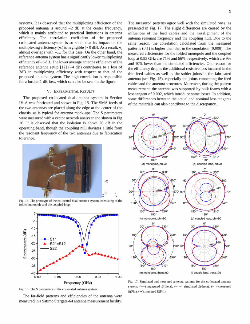
V. EXPERIMENTAL RESULTS
The proposed co-located dual-antenna system in Section
IV-A was fabricated and shown in Fig. 15. The SMA feeds of
the two antennas are placed along the edge at the center of the
chassis, as is typical for antenna mock-ups. The S parameters
were measured with a vector network analyzer and shown in Fig.
16. It is observed that the isolation is above 20 dB in the
operating band, though the coupling null deviates a little from
the resonant frequency of the two antennas due to fabrication
tolerance.
Y
X
Z
Fig. 15. The prototype of the co-located dual-antenna system, consisting of the
folded monopole and the coupled loop.
Fig. 16. The S parameters of the co-located antenna system.
The far-field patterns and efficiencies of the antenna were
measured in a Satimo Stargate-64 antenna measurement facility.
The measured patterns agree well with the simulated ones, as
presented in Fig. 17. The slight differences are caused by the
influences of the feed cables and the misalignment of the
antenna resonant frequency and the coupling null. Due to the
same reason, the correlation calculated from the measured
patterns (0.1) is higher than that in the simulation (0.008). The
measured efficiencies for the folded monopole and the coupled
loop at 0.93 GHz are 71% and 66%, respectively, which are 9%
and 10% lower than the simulated efficiencies. One reason for
the efficiency drop is the additional resistive loss incurred in the
thin feed cables as well as the solder joints in the fabricated
antenna (see Fig. 15), especially the joints connecting the feed
cables and the antenna structures. Moreover, during the pattern
measurement, the antenna was supported by bulk foams with a
loss tangent of 0.002, which introduce some losses. In addition,
some differences between the actual and nominal loss tangents
of the materials can also contribute to the discrepancy.
Fig. 17. Simulated and measured antenna patterns for the co-located antenna
system: (––) measured E(theta), (– –) simulated E(theta), (– -)measured
E(Phi), (--)simulated E(Phi).

10
VI. CONCLUSIONS
In this work, a novel concept for designing multiple antennas
on small terminals was proposed. Specifically, for a
dual-element design, an electric antenna is employed to exploit
chassis excitation, whereas a magnetic antenna avoids such
excitation to achieve good isolation performance. According to
the concept, a folded monopole and a coupled loop is placed on
opposite edges of a 100 mm × 40 mm chassis to form a practical
dual-antenna design. The center frequency of both antennas is
0.93 GHz, and the isolation is above 30 dB within the operating
band. In practice, the coupled loop can be made reconfigurable
to cover a larger bandwidth of 200 MHz. In addition, both
antennas can achieve multiband operation in the 900/1800/2600
MHz with minor modifications, including the addition of two
switches. Furthermore, it is demonstrated that the two antennas
can also be co-located on the same edge of the chassis, to
conserve implementation space. By controlling the phase of the
current on the monopole feed, the isolation of above 20 dB can
be maintained for the entire operating band. A comparison
between the co-located antenna and a typical monopole-PIFA
design was carried out through channel capacity and
multiplexing efficiency. It reveals that a significant capacity
improvement of 2 bits/s/Hz is obtained by the proposed design
for a reference SNR of 20 dB. The multiplexing efficiency also
improves by 4 dB due to higher antenna efficiencies and lower
correlation coefficients. This is despite the fact that the antennas
in the reference monopole-PIFA design are not co-located. The
co-located prototype was fabricated and measured, and the
results were found to be in reasonable agreement with those
from simulations.
ACKNOWLEDGMENT
The authors would like to thank Prof. Jørgen Bach Andersen
of Aalborg University for helpful discussions.
REFERENCES
[1] M. A. Jensen and J. W. Wallace, “A review of antennas and propagation for MIMO wireless communications,” IEEE Trans. Antennas and Propag., vol. 52, no. 11, pp. 2810-2824, Nov. 2004.
[2] B. K. Lau, “Multiple antenna terminals,” in MIMO: From Theory to
Implementation, C. Oestges, A. Sibille, and A. Zanella, Eds. San Diego:
Academic Press, 2011, pp. 267-298.
[3] G. J. Foschini and M. J. Gans, “On limits of wireless communications in a
fading environment when using multiple antennas,” Wireless Personal
Commun., vol. 6, pp. 311-335, Mar. 1998.
[4] Z. Ying and D. Zhang, “Study of the mutual coupling, correlations and
efficiency of two PIFA antennas on a small ground plane,” in Proc. IEEE
Antennas Propagat. Soc. Int. Symp., Washington DC, Jul. 2005, pp.
305-308.
[5] B. K. Lau, J. B. Andersen, G. Kristensson, and A. F. Molisch, “Impact of
matching network on bandwidth of compact antenna arrays,” IEEE
Trans. Antennas Propag., vol. 54, no. 11, pp. 3225-3238, Nov. 2006. [6] H. Li, J. Xiong, and S. He, “Extremely compact dual-band PIFAs for
MIMO application,” Electron. Lett., vol. 45, no. 17, pp. 869-870, Aug. 2009.
[7] A. Diallo, C. Luxey, P. L. Thuc, R. Staraj, and G. Kossiavas, “Enhanced two-antenna structures for universal mobile telecommunications system diversity terminals,” IET Microw. Antennas Propag., vol. 2, no. 1, pp. 93-101, 2008.
[8] H. Li, J. Xiong and S. He, “Compact and low profile co-located MIMO antenna structure with polarization diversity and high port isolation,” Electron. Lett., vol.46, no. 2, pp.108-110, Jan. 2010.
[9] H. Li, J. Xiong, and S. He, “A compact planar MIMO antenna system of four elements with similar radiation characteristics and isolation structure,” IEEE Antennas Wireless Propag. Lett., vol. 8, pp. 1107-1110, 2009.
[10] Y. Gao, X. Chen, Z. Ying, and C. Parini, “Design and performance investigation of a dual-element PIFA array at 2.5GHz for MIMO terminal,” IEEE Trans. Antennas Propag., vol. 55, no. 12, pp. 3433-3441, Dec. 2007.
[11] V. Plicanic, B. K. Lau, A. Derneryd, and Z. Ying, “Actual diversity performance of a multiband antenna with hand and head effects,” IEEE Trans. Antennas Propag., vol. 57, no. 5, pp. 1547-1556, May 2009.
[12] H. Li, Y. Tan, B. K. Lau, Z. Ying, and S. He, “Characteristic mode based tradeoff analysis of antenna-chassis interactions for multiple antenna terminals,” IEEE Trans. Antennas Propag.,vol. 60, no, 2, pp. 409-502, Feb. 2012.
[13] U. Bulus, C. T. Famdie, and K. Solbach, “Equivalent circuit modeling of
chassis radiator,” in Proc. German Microw. Conf. (GeMIC2009),
Munich, Germany, Mar. 16-18, 2009.
[14] R. F. Harrington and J. R. Mautz, “Theory of characteristic modes for
conducting bodies,” IEEE Trans. Antennas Propag., vol. AP-19, no. 5,
pp. 622-628, Sep. 1971. [15] T. Svantesson, M. A. Jensen, and J. Wallace, “Analysis of
electromagnetic field polarizations in multiantenna systems,” IEEE Trans. Wireless Commun., vol. 3, no. 2, pp. 641 – 646, Mar. 2004.
[16] D. Stancil, A. Berson, J. Van’t Hof, R. Negi, S. Sheth, and P. Patel, “Doubling wireless channel capacity using co-polarised, co-located electric and magnetic dipoles,” Electron. Lett., vol. 38, no. 14, pp. 746-747, Jul. 2002.
[17] C. A. Balanis, Antenna Theory: Analysis and Design, 2nd ed. CA:Wiley, 1997, pp. 78, 204-217, 523.
[18] A. Erentok and R. W. Ziolkowski, “An efficient metamaterial-inspired electrically-small antenna,” Microw. Opt. Tech. Lett., vol. 49, no. 6, pp. 1287–1290, Jun. 2007.
[19] A. Erentok and R. W. Ziolkowski, “Metamaterial-inspired efficient electrically small antennas,” IEEE Trans. Antennas Propag., vol. 56, no. 3, pp. 691–707, Mar. 2008.
[20] Y. Yu, J. Xiong, H. Li, and S. He, “An electrically small frequency
reconfigurable antenna with a wide tuning range,” IEEE Antennas
Wireless Propag. Lett., vol. 10, pp. 103-106, 2011.
[21] W. L. Schroeder, A. A. Vila, and C. Thome, “Extremely small wideband
mobile phone antenna by inductive chassis mode coupling,” in Proc. 36th
Europ. Microw. Conf., Manchester, UK, Sep. 10-15, 2006, pp.
1702-1705.
[22] R. Vaughan and J. B. Andersen, Channels, Propagation and Antennas
for Mobile Communications. London, U. K.: IEE, 2003.
[23] G. M. Rebeiz, RF MEMS Theory, Design, and Technology, New York:
Wiley, 2003.
[24] A. Paulraj, R. Nabar, and D. Gore, Introduction to Space-time Wireless
Communications. Cambridge, U. K.: Cambridge University Press, 2003.
[25] J. P. Kermoal, L. Schmacher, K. I. Pedersen, P. E. Mogensen and F.
Frederiksen, “A stochastic MIMO radio channel model with experimental
validation,” IEEE J. Sel. Areas Commun., vol. 20, no. 6, pp. 1211-1226,
Aug. 2002.
[26] R. Tian, B. K. Lau and Z. Ying, “Multiplexing efficiency of MIMO
antennas,” IEEE Antennas Wireless Propag. Lett., vol. 10, pp. 183-186,
2011.