Decomposition-Based Assembly Synthesis for Structural...
13
1 Copyright © 2004 by ASME DECOMPOSITION-BASED ASSEMBLY SYNTHESIS FOR STRUCTURAL STIFFNESS AND DIMENSIONAL INTEGRITY Naesung Lyu, Byungwoo Lee and Kazuhiro Saitou ∗ Department of Mechanical Engineering University of Michigan Ann Arbor, MI 48109-2125, USA E-mail:{nlyu,byungwoo,kazu}@umich.edu ∗ corresponding author ABSTRACT A method for optimally synthesizing multi-component structural assemblies of an aluminum space frame (ASF) vehicle body is presented, which simultaneously considers structural stiffness, manufacturing and assembly cost and dimensional integrity under a unified framework based on joint libraries. The optimization problem is posed as a simultaneous determination of the location and feasible types of joints in a structure selected from the predefined joint libraries, combined with the size optimization for the cross sections of the joined structural frames. The structural stiffness is evaluated by finite element analyses of a beam-spring model modeling the joints and joined frames. Manufacturing and assembly costs are estimated based on the geometries of the components and joints. Dimensional integrity is evaluated as the adjustability of the assembly for the given critical dimensions. The optimization problem is solved by a multi-objective genetic algorithm. An example on an ASF of the mid-size passenger vehicle is presented, where the representative designs in the Pareto set are examined with respect to the three design objectives. INTRODUCTION Many modern mechanical products, such as ships hulls, airplanes and automotive bodies, are fairly complex that it is almost impossible (or too expensive) to be manufactured in one piece. Therefore, most products are made of hundreds of components joined together. Hence, during the conceptual stage of such products, designers need to determine the set of components and the methods of joining the components by decomposing the entire product geometry. In the automotive industry, for example, a handful of basic decomposition schemes considering geometry, functionality and manufacturing issues have been applied in this process. However, these decomposition schemes depend mainly on the designers’ experiences, which may cause the following problems: 1. Insufficient stiffness of assembled structure: Structural characteristics of two components jointed together are generally different from the one of a component of the same geometry without a joint, and the difference largely depends on the location and geometry of joints and joining methods. Therefore, unsystematic decisions on these may cause assembled structures incapable to meet the desired stiffness specifications. 2. Manufacturing and/or assembly problems: Feasibility and difficulty in manufacturing and assembly of components largely depend on the geometry of components and joints, and assembly processes. Therefore, unsystematic decisions on these may lead to a design that cannot be economically manufactured and/or assembled. 3. Insufficient adjustability for critical dimensions: To reduce the cost of producing high-tolerance components, the dimensional integrity in large-scale assemblies is often achieved by the adjustment of the critical product dimensions (Key Characteristics, KC) during assembly processes when the parts are located in fixtures. To enable these in-process dimensional adjustments, joints must allow a small relative motion along the direction of the KC at the assembly step where the KC is being achieved (Figure 1). Therefore, unsystematic decisions on the location and Proceedings of IMECE04 2004 ASME International Mechanical Engineering Congress and Exposition November 13-20, 2004, Anaheim, California USA IMECE2004-62229
Transcript of Decomposition-Based Assembly Synthesis for Structural...

DECOMPOSITION-BASED ASSEMBLY SYNTHESIS FOR STRUCTURAL STIFFNESS AND DIMENSIONAL INTEGRITY
Naesung Lyu, Byungwoo Lee and Kazuhiro Saitou∗ Department of Mechanical Engineering
University of Michigan Ann Arbor, MI 48109-2125, USA
E-mail:{nlyu,byungwoo,kazu}@umich.edu
Proceedings of IMECE04 2004 ASME International Mechanical Engineering Congress and Exposition
November 13-20, 2004, Anaheim, California USA
IMECE2004-62229
ABSTRACT A method for optimally synthesizing multi-component
structural assemblies of an aluminum space frame (ASF) vehicle body is presented, which simultaneously considers structural stiffness, manufacturing and assembly cost and dimensional integrity under a unified framework based on joint libraries. The optimization problem is posed as a simultaneous determination of the location and feasible types of joints in a structure selected from the predefined joint libraries, combined with the size optimization for the cross sections of the joined structural frames. The structural stiffness is evaluated by finite element analyses of a beam-spring model modeling the joints and joined frames. Manufacturing and assembly costs are estimated based on the geometries of the components and joints. Dimensional integrity is evaluated as the adjustability of the assembly for the given critical dimensions. The optimization problem is solved by a multi-objective genetic algorithm. An example on an ASF of the mid-size passenger vehicle is presented, where the representative designs in the Pareto set are examined with respect to the three design objectives.
INTRODUCTION Many modern mechanical products, such as ships hulls,
airplanes and automotive bodies, are fairly complex that it is almost impossible (or too expensive) to be manufactured in one piece. Therefore, most products are made of hundreds of components joined together. Hence, during the conceptual stage of such products, designers need to determine the set of components and the methods of joining the components by decomposing the entire product geometry. In the automotive
∗ corresponding author
industry, for example, a handful of basic decomposition schemes considering geometry, functionality and manufacturing issues have been applied in this process. However, these decomposition schemes depend mainly on the designers’ experiences, which may cause the following problems: 1. Insufficient stiffness of assembled structure: Structural
characteristics of two components jointed together are generally different from the one of a component of the same geometry without a joint, and the difference largely depends on the location and geometry of joints and joining methods. Therefore, unsystematic decisions on these may cause assembled structures incapable to meet the desired stiffness specifications.
2. Manufacturing and/or assembly problems: Feasibility and difficulty in manufacturing and assembly of components largely depend on the geometry of components and joints, and assembly processes. Therefore, unsystematic decisions on these may lead to a design that cannot be economically manufactured and/or assembled.
3. Insufficient adjustability for critical dimensions: To reduce the cost of producing high-tolerance components, the dimensional integrity in large-scale assemblies is often achieved by the adjustment of the critical product dimensions (Key Characteristics, KC) during assembly processes when the parts are located in fixtures. To enable these in-process dimensional adjustments, joints must allow a small relative motion along the direction of the KC at the assembly step where the KC is being achieved (Figure 1). Therefore, unsystematic decisions on the location and
1 Copyright © 2004 by ASME

geometry of joints and assembly sequences may prevent the in-process adjustability of critical dimensions, leading to the poor dimensional integrity of assembled structures.
Figure 1. Two assembly sequences for automobile floor pan design (modified from [1]), where the total length is the critical dimension (KC). (a) Poor design (cannot adjust total length) and (b) better design (can adjust total length).
The above three problems are usually found in the production/testing phases and require expensive and time-consuming iteration procedures. Therefore, introducing a cost-effective but systematic optimization method in determining the components set considering overall structural characteristics, manufacturing and assembly costs, and dimensional integrity altogether will have a significant impact on industry.
Assembly synthesis is a process of determining the optimal components set through the decomposition of the end product design prior to the detailed component design phase [2]. As an extension of our past researches on the decomposition-based assembly synthesis [2-7], this paper introduces a method for determining the components set of aluminum space frame (ASF) vehicle bodies using pre-analyzed joint libraries defined at each potential joint location. The uniqueness of the present work is the simultaneous consideration of stiffness, manufacturing and assembly cost [4,5] and dimensional integrity [3,7] , which are considered separately in our previous work, under a unified framework based on joint libraries.
RELATED WORK
DFA/DFM and Assembly Synthesis Boothroyd and Dewhurst [8] are regarded as major
establishers of design for assembly (DFA) and design for manufacturing (DFM) concepts, a collection of design methods to identify and alleviate manufacturing problems at the product design stage. They proposed to minimize the total assembly cost with the reduction of part count, followed by the local design changes of the remaining parts [9]. Conventional DFA/DFM methods assume the pre-determined components with given geometries and, therefore, are limited to the design improvements by locally modifying the given geometries. Decomposition-based assembly synthesis [2-7], on the other hand, emphasizes the determination of components prior to the detailed design stages. Starting with no prescribed components, the method decomposes the component geometry so the optimal components set and joint configurations best achieving the design criteria on each component and joint, as well as the
assembles product. The criteria attempted in the previous work includes structural strength [2], structural stiff ness [4,5], component modularity [6], and dimensional integrity [3,7].
Automotive Body Structural Modeling During the early stage of automotive body-in-white (BIW)
design procedures, simple beam/spring models are widely used. In the beam/spring models, difficulties often arise in modeling the structural property of joints. Modeling joints as torsional springs is a popular method [10] due to its simplicity, and the equivalent torsional spring rates of the joints are identified from physical or numerical (by using detailed FEA models) experiments. Lee and Nikolaidis [11] proposed a 2-D joint model considering the flexibility of joints, the offset of rotation centers, and coupling effects between the movements of joint branches. Kim, et. al. [12] discussed the accuracy of FEA based joint rate evaluations regarding transformation error from shell element model to spring rate and proposed their own model [13]. Long [14] presented two tools that link the performance targets for a joint in a BIW to its geometry. The first tool, called translator A, predicts the structural performance of a given joint geometry using artificial neural network (ANN) and response surface method (RSM). The second tool, called translator B, solves the inverse problem of finding a joint geometry that meets the given performance targets, using the translator A and sequential quadratic programming (SQP). Recently, Nishigaki, et. al. [15] proposed a tool based on First Order Analysis (FOA) to design basic layouts of automotive structures considering models of beam and spring elements. The above works, however, mainly focused on the analyses of structural properties of joints, separately or as an integral of an overall structure, and do not addresses the automated synthesis of joint locations and designs within a BIW as addressed in this paper.
Aluminum Space Frame (ASF) Design Aluminum applications in the automotive industries have
drawn a significant attention in the last two decades mainly due to the increasing demands on the high gas-mileage, light-weight and environment-friendly vehicles. Since the BIW accounts for about one third of the total weight of a passenger vehicle, a significant amount of researches have been concentrated on this area [16-19], resulting in a number of mass-produced vehicles with ASF including Acura’s NSX [20], Audi’s A2 and A8 [21], BMW’s Z8 [22] and etc.
Ahmetoglu [23] discussed the design of extruded profiles, bending, friction and formability of aluminum components for ASF body design. Chung, et. al. [24] studied the joint designs of an ASF by comparing FE models with experimental results. Powell, et. al. [25] and Barnes, et. al. [26,27] summarized the joining technologies currently used in aluminum structure vehicles including resistance spot welding (RSW), gas metal arc welding (GMAW), self-piercing joint, and laser welding. Motivated by the increased attention to AFS vehicle bodies, this provides a method of determining the optimal component set and joint configurations of ASF vehicle bodies considering
2 Copyright © 2004 by ASME

structural characteristics, manufacturing cost, assembly cost and dimensional adjustability.
Figure 2. Examples of the Aluminum Space Frames [21]
Dimensional Integrity Our previous work [7] discussed an algorithm of assembly
synthesis focused on the in-process adjustability and non-forced fit. The algorithm enumerates all possible assembly syntheses with the accompanying assembly sequences which, in combination, achieve dimensional adjustability for critical dimensions and non-forced fit between parts. It recursively decomposes a product from its final shape into parts and assigns joint configurations according to simple rules drawn from a related literature on assembly design [1]. Based on the AND/OR graph for assembly sequence planning [28], an augmented AND/OR graph has been devised to represent the results. As an alternative to the enumeration-based approach, we have presented in [3] an optimization-based method of assembly synthesis for in-process dimensional adjustability using a genetic algorithm (GA), and its application to a 3D automotive space frame. Each candidate assembly generated by GA is evaluated using an internal optimization routine that computes the subassembly partitioning for optimal in-process adjustability, by solving an equivalent minimum cut problem on weighted graphs.
In the present paper, the approach in [3] is adopted due to its compatibility to the method of evaluating structural stiffness and manufacturing and assembly costs described in [5].
APPROACH This section describes the method for synthesizing multi-
components ASF using the joint library which simultaneously identify the optimal components set and component/joint designs considering the stiffness of the assembled structure, manufacturing/assembly cost and dimensional adjustability. This method consists of the following two major steps:
1. Geometry of the entire structure is transformed into a
structural topology graph, representing the liaisons between basic members, the smallest decomposable components of the given structure, identified by the potential joint locations specified by the designer.
2. The product topology graph is decomposed through an optimization procedure into the subgraphs representing components by using a set of joints in the joint library.
Details of the above two steps are described below, with a
sample space frame structure shown in Figure 3. As illustrated in Figure 3 (b), it is assumed that frames are extruded tubes, bent or welded with cast “sleeves” at joints, following a typical construction of ASF structures.
Figure 3. (a) A sample space frame structure with two KCs (KC1, KC2), and (b) a possible components set with 4 components, shown in different shades.
Figure 4. Potential joint locations (grey boxes) and possible joint types at each location (joint library). Arrow(s) near each joint type indicates the adjustable direction during assembly.
Step1: Construction of structural topology graph The method requires the designer to specify the potential
joint locations to guarantee the feasibility of the final design to frame manufacturing and joining methods.
Figure 4 illustrates an example of six potential joint locations shown as grey boxes. For each potential joint location, the designer specifies feasible (potentially different) joint types to be included in the joint library. For example, four joint types (a1~a4) are assumed as available at location A in Figure 4. Each joint type is associated with the joint design variables specifying the cross sections of the joined frames and the amount of welds, with which the structural properties of a joint are determined as described in the next subsection.
The basic members can be identified from the specified potential joint locations (Figure 5 (a)) and the structural
3 Copyright © 2004 by ASME

topology graph G = (M, T) is constructed from the basic members (Figure 5 (b)) such that: Basic member mi is represented as a node ni in M. The liaison between two basic members mi and mj is
represented as edge e = {ni, nj} in T.
Step2: Decomposition of structural topology graph The structural topology graph G = (M, T) is decomposed
by selecting a joint type in the library at each potential joint location. Based on the selected joint types, the corresponding edges in G are removed and G is decomposed into subgraphs. For example, by selecting joint type a3 in the joint library for location A in Figure 6, the corresponding edges {1,2} and {1,6} are removed.
Figure 5. (a) 7 basic members and (b) structural topology graph with 7 nodes and 10 edges
Figure 6. Selected joint types and topology graph with the corresponding edges removed
The selection of joint types and the removal of the
corresponding edges in G result in subgraphs of G, each of which corresponds to a component. The cross sectional dimensions of a component are then set as the averages of the ones in the joining frames (basic members) associated with the selected joint types in the component, which are subsequently used for retrieving the pre-computed structural properties of the joints from the joint library. The selection of the joint types in
Figure 6, for example, results in 4 subgraphs (Figure 7 (a)) and the corresponding components (Figure 7 (b)).
Figure 7. (a) 4 subgraphs and (b) corresponding 4 components
Within an optimization loop, a decomposed structure
consisting of components and joints obtained as above is evaluated based on structural stiffness, manufacturing/assembly cost, and dimensional adjustability. While this paper addresses stiffness as a structural criterion, other structural criteria, such as crash-worthiness, can be incorporated by using appropriate structural analyses. Structural stiffness
As in [5], the structural stiffness of the assembled structure is evaluated as a negative of the displacements at the specified locations in the assembled structure under given loading conditions. The displacements are calculated using the finite element analyses, where the components and joints are modeled as beam elements and torsion spring elements, respectively. As an example, a structure with 4 beam components in Figure 8 (left) is modeled as a beam-spring FE model in Figure 8 (right), where T-joint is modeled as three beam elements connected by torsional spring elements k0, k1, and k2. Each of the three spring elements has torsional stiffness (rate) around each of the three local orthogonal axes attached to the joint. Note that the relative translations of the spring elements are constrained.
Figure 8. Sample structure with 4 beam components and its beam-spring FE model.
4 Copyright © 2004 by ASME

Figure 9. (a) Detailed 3D solid model of a joint and (b) corresponding FE joint model with plate elements for beams, solid elements for casting, and plate elements for welding.
Figure 10. Estimating torsional spring rates using FE analysis
The rate of the torsional spring elements are estimated by
the finite element analyses of the detailed model of the joint, where frames are modeled with plate elements, the cast sleeve is modeled as solid elements, and welds joining the frames and the sleeve are modeled as plate elements, as illustrated in Figure 9.
Figure 10 illustrates the loading and boundary conditions for calculating torsional spring rates of in-plane rotation. To facilitate the load application and the measurement of distortion angles, a rigid beam element is added to the center of the frame subject to rotation. The distortion angles 0θ , 1θ , and 2θ account for the effects of, respectively, k1 and k2, k0, and k2, and k0 and k1. Assuming moment arm length L, the following equations are used to estimate k0, k1, and k2 for in-plane rotation:
−+=
+−=
++−=
210,2
210,1
210,0
1112
1112
1112
θθθ
θθθ
θθθ
PLk
PLk
PLk
InPlane
InPlane
InPlane
(1)
The other two components of torsional spring rates are calculated in a similar manner.
The values of the torsional spring rates for typical joint types, cross sectional dimensions of the joined frames, and amount of welds are pre-computed to produce a set of training
data for an Artificial Neural Network (ANN) that implements the joint library. Similar to the translator A of [14], this approach allows the spring rates of a joint can simply be retrieved from the joint library without computational overheads during optimization. Manufacturing/assembly cost
The manufacturing cost of components is evaluated as a negative of the total cost of producing components. As stated earlier, it is assumed that frames are extruded tubes, bent or welded with cast “sleeves” at joints, following a typical construction method of ASF. For example, the design in Figure 11 (a) is composed of four frames (Figure 11 (b)) and 5 cast sleeves (Figure 11 (c)). The cost of producing components is estimated by the sum of the cost of extrusion die (assumed as proportional to the size and complexity of the frame cross sections) and the cost of bending operations (assumed as proportional to the number of bending). The cost of producing cast sleeves is estimated by the cost of casting, which is assumed as simply proportional to its volume.
The assembly cost is calculated as a negative of the total cost of joining. As in [5], the method of joining is assumed to be the GMAW (Gas Metal Arc Welding), widely used for ASF [23]. The welds are applied between the frames and the cast sleeves at joints. The cost is assumed to be proportional to the volume of total welds, calculated from the total welding length multiplied by weld thickness. Total manufacturing/assembly cost is the sum of manufacturing and assembly costs.
Figure 11. (a) Sample design, (b) 4 components with 2 bends (indicated as arc-arrows), and (c) 5 cast sleeves for joining. Dimensional adjustability
Dimensional adjustability of candidate component set and joint types is evaluated by estimating the in-process adjustability of the KCs. Adopting the approach in [3], this is done by an internal routine that computes a subassembly partitioning of given component set and joint type for optimal in-process adjustability, by solving the equivalent minimum cut problem on the weighted graphs.
First, the structural topology graph G = (M, T) is transformed to a configuration graph, C = (M, T, A), where A is the set of edges representing the KCs between a pair of basic members (double-line edges in Figure 12 (b)). Note that two KCs in the structure (Figure 12 (a)) are represented as two
5 Copyright © 2004 by ASME
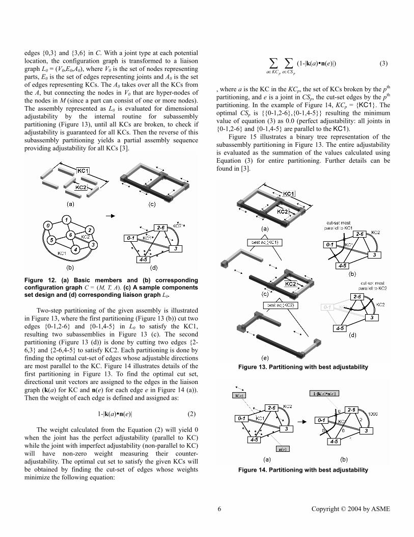
edges {0,3} and {3,6} in C. With a joint type at each potential location, the configuration graph is transformed to a liaison graph L0 = (V0,E0,A0), where V0 is the set of nodes representing parts, E0 is the set of edges representing joints and A0 is the set of edges representing KCs. The A0 takes over all the KCs from the A, but connecting the nodes in V0 that are hyper-nodes of the nodes in M (since a part can consist of one or more nodes). The assembly represented as L0 is evaluated for dimensional adjustability by the internal routine for subassembly partitioning (Figure 13), until all KCs are broken, to check if adjustability is guaranteed for all KCs. Then the reverse of this subassembly partitioning yields a partial assembly sequence providing adjustability for all KCs [3].
Figure 12. (a) Basic members and (b) corresponding configuration graph C = (M, T, A). (c) A sample components set design and (d) corresponding liaison graph L0.
Two-step partitioning of the given assembly is illustrated in Figure 13, where the first partitioning (Figure 13 (b)) cut two edges {0-1,2-6} and {0-1,4-5} in L0 to satisfy the KC1, resulting two subassemblies in Figure 13 (c). The second partitioning (Figure 13 (d)) is done by cutting two edges {2-6,3} and {2-6,4-5} to satisfy KC2. Each partitioning is done by finding the optimal cut-set of edges whose adjustable directions are most parallel to the KC. Figure 14 illustrates details of the first partitioning in Figure 13. To find the optimal cut set, directional unit vectors are assigned to the edges in the liaison graph (k(a) for KC and n(e) for each edge e in Figure 14 (a)). Then the weight of each edge is defined and assigned as:
1-|k(a) n(e)| (2) The weight calculated from the Equation (2) will yield 0
when the joint has the perfect adjustability (parallel to KC) while the joint with imperfect adjustability (non-parallel to KC) will have non-zero weight measuring their counter-adjustability. The optimal cut set to satisfy the given KCs will be obtained by finding the cut-set of edges whose weights minimize the following equation:
∑ ∑∈ ∈p pKCa CSe
(1-|k(a) n(e)|) (3)
, where a is the KC in the KCp, the set of KCs broken by the pth partitioning, and e is a joint in CSp, the cut-set edges by the pth partitioning. In the example of Figure 14, KCp = {KC1}. The optimal CSp is {{0-1,2-6},{0-1,4-5}} resulting the minimum value of equation (3) as 0.0 (perfect adjustability: all joints in {0-1,2-6} and {0-1,4-5} are parallel to the KC1).
Figure 15 illustrates a binary tree representation of the subassembly partitioning in Figure 13. The entire adjustability is evaluated as the summation of the values calculated using Equation (3) for entire partitioning. Further details can be found in [3].
Figure 13. Partitioning with best adjustability
Figure 14. Partitioning with best adjustability
6 Copyright © 2004 by ASME

Figure 15. Binary tree representation of the subassembly partitioning illustrated in Figure 13.
MATHEMATICAL FORMULATION
Definition of design variables A design is uniquely specified by 1) the joint types at all
possible joint locations, 2) the cross sectional dimensions of all basic members, and 3) the amount of welds at all joints, which are represented by three vectors x, y, and z, respectively:
1 2 n
B
n
J J J
SW
∈ × × ×
∈
∈
Lxyz
(4)
, where • n is the number of possible joint locations in the structure, • B is the number of basic members in the structure, • Ji is the joint library at the i-th possible joint locations, • S is the set of feasible cross sectional dimensions, • W is the set of feasible amount of welds. Note the elements of vectors y and z can also be vectors depending on the definitions of S and W, as appeared in the following case study.
Definition of objective functions Using the design variables x, y, and z, the three objective
functions described in the previous section are given as follows:
fstiff(x,y,z) = − DISP(XSEC(x,y),JRATE(XSEC(x,y),z)) (5) fmgf,assm(x,y,z) = fmfg(x,y)+fassm(z) (6)
( )( )
( ) 1 ( ) ( )p p
adjp P a KC e CS
f a e∈ ∈ ∈
= − − •∑ ∑ ∑ k nx
x (7)
, where
{ }1
0
1
0
( ) , , )
,
n
mfgi
m
i
f , i i
i
−
=
−
=
= − +
−
∑
∑
x y x y x
x
DIEC(COMP( ), ) BNDC(COMP( )
CASTC( ) (8)
1
0( ) , ,
m
assm wi
f C i i−
=
= − ×∑z z zWLDL( ) WLDT( ) (9)
and • n and m are the numbers of components and joints in a
decomposed structure, respectively. • DISP is the sum or maximum of the displacements at a
predefined point(s) of the beam-torsional spring FE model of an assembled structure. The structural stiffness explained in Step 2 is calculated as the negative of this value.
• XSEC(x, y) is the cross sectional properties of the components specified by x with the beam cross sectional dimensions specified by y.
• JRATE is the torsional spring rates at each joint with cross sectional properties XSEC and weld amount z. This function is computed using the ANNs that map the design variables to the torsional spring rates.
• COMP(i,x) is the ith structural component specified by x. • DIEC and BNDC are the cost of extrusion die and bending
operation of a component, respectively, and CASTC(i,x) is the casting cost at the i-th joint specified by x. The manufacturing cost explained in Step 2 is calculated as the negative of the sum of the DIEC and BNDC for all components plus the sum of the CASTC for all joint locations.
• Cw is the cost of welding operation per unit weld volume. • WLDL(i,z) and WLDT(i,z) are the length and thickness of the
welds at the ith joint as specified by z. The assembly cost explained in the Step 2 is calculated as the negative of the sum of the weld costs estimated from the weld volume, WLDL(i,z)×WLDT(i,z), for all joint locations.
• P(x) is the set of all partitions p in the assembly defined by x.
• KCp is the set of KCs of the pth partitioning • CSp is the cut-set edges in the pth partitioning • a is the KC in the KCp and e is a joint in CSp. • k(a) and n(e) are normal vector for a and e, respectively.
Optimization problem Finally, the problem can be simply formulates as the
following multi-objective optimization with no explicit constraints:
maximize: { fstiff(x,y,z), fmgf,assm(x,y,z), fadj(x)} subject to:
1 2 n
B
n
J J J
SW
∈ × × ×
∈
∈
Lxyz
(10)
A modified Non-Dominated Sorting Genetic Algorithm-II
(NSGA-II) [29] is used for the above problem due to the discrete nature of the design variables. Some enhancements to the conventional NSGA-II are made in the niching based on the distances in function domain and stochastic universal sampling, successfully applied in our previous works [30]. A chromosome
7 Copyright © 2004 by ASME

c (an internal representation of design variables for Genetic Algorithms) is a simple list of the 3 design variables:
c = (x, y, z) (11)
Since the information in x, y, and z are linked to the physical geometry of structure, the conventional one point or multiple point crossover for linear chromosomes [31] are ineffective in preserving high-quality building blocks. For this type of problems, direct crossover has been successfully applied to improve the performance [30,32], whose details can be found in [4] along with the description of the modified NSGA-II.
CASE STUDY This section presents a case study on an aluminum space
frame (ASF) of a passenger vehicle. The actual vehicle design (Figure 16 (a)) is first simplified and five (5) KSs are assigned (Figure 16 (b)), where all frames are modeled as square tubes with identical external dimensions and with possibly different internal thicknesses. Since the actual vehicle body is a mixture of extruded and cast parts, only the portions corresponding to the extruded parts are subject to decomposition in the simplified model. Assuming the left-right symmetry of the body, the design variables are assigned only to left half of the body structure.
Table 1. Material Properties in ASF model
Process Name E* Poisson’s ratio density**Extrusion A6061-T6 70.5 0.33 2700.00 Casting A356.0-T6 72.4 0.33 2685.00 Welding A4043 70.5 0.33 2700.00
*E: Young’s Modulus [GPa], ** Density: [kg/m3]
Table 1 shows the material properties used in this case study. Total of 30 possible joint locations are specified as in Figure 17 (a). These locations are classified as A, B, and C, each of which has feasible joint types in Figure 17 (b) with 90 or 180 degree angles between the joined frames. Location type A has two joint types a0 and a1. In a0, beams 0 and 1 are one component ((0,1)) while in a1, beams 0 and 1 are welded with cast sleeve ((0),(1)). Location type B has three configuration designs b0, b1, b2. In b0, beams 0 and 2 is one component, joined to 1 ((0,2),(1)). Similarly, b1 and b2 have two components ((0,1),(2)) and ((0),(1,2)), respectively. For location type C, c0, c1 and c2 have joint types ((1,2),(0)), ((1),(0,2)), and ((0,1),(2)), respectively.
Based on the possible joint locations, 42 basic members are identified (Figure 18, (a)), from which structural topology graph G with 42 nodes and 66 edges is constructed (Figure 18, (b)). As in Figure 19 (a), variable yi has two elements, yi 0 and yi
1. The first element yi 0 represents the upper/lower thickness of the beam when the beam is placed on the horizontal plane. In this case, the second element yi 1 represents the side thickness of the beam. Similarly, when the beam is placed on the vertical plane, yi 0 represents the front/back thickness of the beam while
yi 1 represents the side thickness of the beam. Figure 19 (b) illustrates the definition of variable zi, where zi 0 is the thickness of weld between cast and component 0 and zi 1 is the thickness of weld between cast and component 1.
Figure 16. (a) ASF for a passenger car and (b) simplified frame model used in the case study with 5 KCs (KC1~KC5).
Figure 17. (a) potential joint locations and (b) possible joint types (joint library) for each location type. Arrows in (b) indicate the adjustable directions.
The stiffness of the assembled structure is calculated
considering the maximum displacement of floor frame under bending loads (Figure 20). The main loads of powertrain Fpt, the front passengers/seats Fpf, the rear passenger/seats Fpr, and the luggage Fl are only considered [33], where the magnitude of each load is the weight of the corresponding component multiplied by a dynamic load factor. The rear suspension locations are constrained in x, y, and z translations while the front suspension locations are constrained in z (upward)
8 Copyright © 2004 by ASME

translation only. Table 2 shows magnitude of the applied loads and the dynamic load factor.
Figure 18. (a) Resulting 42 basic members and (b) structural topology graph with 42 nodes and 66 edges.
Figure 19. (a) Beam cross sectional design variable (beam thickness, yi 0 and yi 1) and (b) joint design variable (weld thickness, zi 0 and zi 1).
Figure 20. Loading condition and boundary condition [33] Table 2. Applied load and dynamic load factor (One side)
Default value* Dynamic factor Applied value* Fpt 4,000.0 2.0 8,000.0 Fpf 1,200.0 2.0 2,400.0 Fpr 1,200.0 2.0 2,400.0 Fl 500.0 2.0 1,000.0
* Unit [N]
As a training data for the artificial neural network (ANN), the detailed 3D FE models of 7 joint types (a1, b0~b2, c0~c2) in Figure 17 (b) are analyzed. For joint type a1, 3 torsional spring rates (x, y, and z components between two joining frames) are calculated. For the other joint types, 9 torsional spring rates (x, y, and z components among three joined frames in Figure 8) are calculated. For each spring rate, a radial-based neural network [34] is built with 6 input nodes (two y’s for two joined frames and one z for the joint), 1,250 hidden layer nodes and 1 output node (joint rate) using Matlab [35]. The networks are trained to reach a satisfactory convergence (RMS Error < 10%).
In the case study, population of 1,000 designs and 50 generations are used as the parameter values for GAs. The number of generation (50) was used as the termination condition. Using a PC with hyper-threaded Pentium 4 3.07 GHz, one optimization run takes approximately 2 days.
Figure 21 shows the Pareto solutions at the terminal generation. Figure 21 (a) shows 3-D view of Pareto set and (b)~(d) illustrate 2-D projection onto the two objectives. Three representative designs R1, R2 and R3 are examined below.
Figure 21. Designs at the terminal condition (generation = 50). Pareto solutions are colored as darker dots.
Design R1 (Figure 22 (c), and Figure 23 (a)) shows good results both in stiffness and manufacturing/assembly cost. This structure has long one-piece rocker rails (C1) with thick wall dimensions which seem to increase the stiffness of the structure under global bending loading (Figure 22 (c)). Also, this design minimizes number of beam components (minimizing extrusion dies) and joint casting components (minimizing number of casting sleeves) by not having joints at location type A (See Figure 17), resulting in minimizing manufacturing and assembly cost. However, the small number of components
9 Copyright © 2004 by ASME
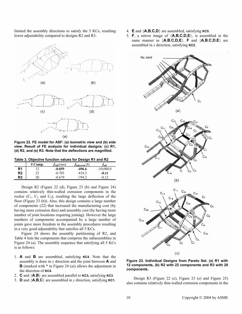
limited the assembly directions to satisfy the 5 KCs, resulting lower adjustability compared to designs R2 and R3.
Figure 22. FE model for ASF: (a) Isometric view and (b) side view. Result of FE analysis for individual designs: (c) R1, (d) R2, and (e) R3. Note that the deflections are magnified. Table 3. Objective function values for Design R1 and R2
# Comp. fstiff [mm] fmfg,assm [$] fadj R1 12 -0.059 -496.6 -10,000.0 R2 22 -0.703 -818.2 -0.11 R3 20 -0.679 -794.2 -0.12
Design R2 (Figure 22 (d), Figure 23 (b) and Figure 24)
contains relatively thin-walled extrusion components in the rocker (C1, C2 and C4), resulting the large deflection of the floor (Figure 23 (b)). Also, this design contains a large number of components (22) that increased the manufacturing cost (by having more extrusion dies) and assembly cost (by having more number of joint locations requiring joining). However the large numbers of components accompanied by a large number of joints gave more freedom in the assembly procedures resulting in a very good adjustability that satisfies all 5 KCs.
Figure 24 shows the assembly partitioning of R2, and Table 4 lists the components that comprise the subassemblies in Figure 24 (a). The assembly sequence that satisfying all 5 KCs is as follows:
1. A and B are assembled, satisfying KC4. Note that the
assembly is done in y direction and the joint between A and B (marked with * in Figure 24 (a)) allows the adjustment in the direction of KC4.
2. C and {A,B} are assembled parallel to KC3, satisfying KC3. 3. D and {A,B,C} are assembled in y direction, satisfying KC1.
4. E and {A,B,C,D} are assembled, satisfying KC5. 5. F, a mirror image of {A,B,C,D,E}, is assembled in the
same manner as {A,B,C,D,E}. F and {A,B,C,D,E} are assembled in x direction, satisfying KC2.
Figure 23. Individual Designs from Pareto Set. (a) R1 with 12 components, (b) R2 with 22 components and R3 with 20 components.
Design R3 (Figure 22 (c), Figure 23 (e) and Figure 25) also contains relatively thin-walled extrusion components in the
10 Copyright © 2004 by ASME
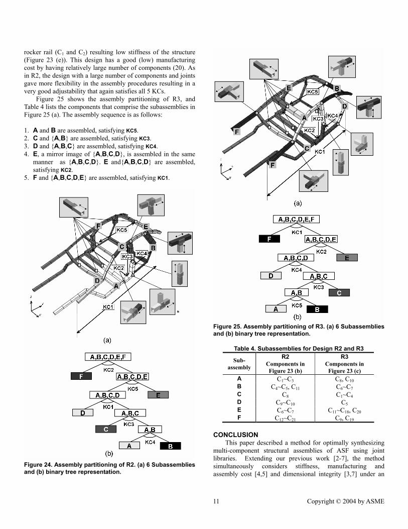
rocker rail (C1 and C2) resulting low stiffness of the structure (Figure 23 (e)). This design has a good (low) manufacturing cost by having relatively large number of components (20). As in R2, the design with a large number of components and joints gave more flexibility in the assembly procedures resulting in a very good adjustability that again satisfies all 5 KCs.
Figure 25 shows the assembly partitioning of R3, and Table 4 lists the components that comprise the subassemblies in Figure 25 (a). The assembly sequence is as follows:
1. A and B are assembled, satisfying KC5. 2. C and {A,B} are assembled, satisfying KC3. 3. D and {A,B,C} are assembled, satisfying KC4. 4. E, a mirror image of {A,B,C,D}, is assembled in the same
manner as {A,B,C,D}. E and{A,B,C,D} are assembled, satisfying KC2.
5. F and {A,B,C,D,E} are assembled, satisfying KC1.
Figure 24. Assembly partitioning of R2. (a) 6 Subassemblies and (b) binary tree representation.
Figure 25. Assembly partitioning of R3. (a) 6 Subassemblies and (b) binary tree representation.
Table 4. Subassemblies for Design R2 and R3
Sub-assembly
R2 Components in Figure 23 (b)
R3 Components in
Figure 23 (c) A C1~C3 C8, C10 B C4~C5, C11 C6~C7 C C8 C1~C4 D C9~C10 C5 E C6~C7 C11~C18, C20 F C12~C21 C9, C19
CONCLUSION This paper described a method for optimally synthesizing
multi-component structural assemblies of ASF using joint libraries. Extending our previous work [2-7], the method simultaneously considers stiffness, manufacturing and assembly cost [4,5] and dimensional integrity [3,7] under an
11 Copyright © 2004 by ASME

unified framework based on joint libraries. The optimization problem is posed as a simultaneous determination of the location and feasible types of joints in a structure selected from the predefined joint libraries, combined with the size optimization for the cross sections of the joined structural frames. The structural stiffness is evaluated by finite element analyses of a beam-spring model modeling the joints and joined frames. Manufacturing and assembly costs are estimated based on the geometries of the components and joints. Dimensional integrity is evaluated as the adjustability of the assembly for the given critical dimensions. The optimization problem is solved by a multi-objective genetic algorithm. The case study on an ASF of the mid-size passenger vehicle clearly demonstrated the effectiveness of the method in synthesizing multiple high-quality designs with different trade-offs among the given objectives, each of which can be further examined by the human designer during the detailed design phase.
ACKNOWLEDGMENTS The authors acknowledge funding provided by Toyota
Motor Corporation and National Science Foundation under CAREER Award (DMI-9984606) for this research. We thank Mr. Karim Hamza at Discrete Design Optimization Laboratory at the University of Michigan for providing his FEM code. Any opinions, findings, and conclusions or recommendations expressed in this material are those of the authors and do not necessarily reflect the views of the National Science Foundation.
REFERENCES [1] Whitney, D. E., Mantripragada, R., Adams, J. D., and Rhee, S. J.,
1999, "Designing assemblies," Research in Engineering Design, vol. 11, pp. 229-253
[2] Yetis, A. and Saitou, K., 2002, “Decomposition-Based Assembly Synthesis Based on Structural Considerations,” ASME Journal of Mechanical Design, vol. 124, pp. 593–601.
[3] Lee, B. and Saitou, K., 2003, "Assembly Synthesis with Subassembly Partitioning for Optimal In-Process Dimensional Adjustability," Proceedings of the 2003 ASME Design Engineering Technical Conferences, Chicago, Illinois, September 2-6, DETC2003/DAC-48729. An extended version submitted to ASME Journal of Mechanical Design.
[4] Lyu, N. and Saitou, K., 2003, “Decomposition-based assembly synthesis of a 3D Body-In-White for structural stiffness”, Proceedings of the 2003 IMECE, Washington, D.C., Nov 15-21, 2003, IMECE2003-43130. An extended version to appear in ASME Journal of Mechanical Design.
[5] Lyu, N. and Saitou, K., 2004, “Decomposition-based assembly synthesis of Space Frame structures using Joint library”, Proceedings of the 2004 ASME Design Engineering Technical Conferences, Salt Lake City, Utah, September 28-October 2, DETC2004/DAC-57301. An extended version submitted to ASME Journal of Mechanical Design.
[6] Cetin, O and Saitou, K., 2003, "Decomposition-based assembly synthesis of multiple structures for minimum production cost" Proceedings of the 2003 ASME International Mechanical Engineering Congress and R&D Exposition, Washington, D.C.,
Nov 15-21, IMECE2003-43085. An extended version to appear in ASME Journal of Mechanical Design.
[7] Lee, B. and Saitou, K., 2003, "Decomposition-based Assembly Synthesis for In-Process Dimensional Adjustability," ASME Journal of Mechanical Design, vol. 125, pp. 464-473.
[8] Boothroyd, G. and Dewhurst, P., 1983. Design for Assembly Handbook, University of Massachusetts, Amherst.
[9] Boothroyd, G. and Dewhurst, P., 1994. Product Design for Manufacturing and Assembly, Marcel Dekker, New York.
[10] Chang, D., 1974. “Effect of flexible connections on body structural response”, SAE Transaction, vol. 83, pp. 233-244.
[11] Lee, K. and Nikolaidis, E., 1992, “A two-dimensional model for joints in vehicle structures”, Computers and Structures, vol. 45 (4), pp. 775-784.
[12] Kim, Y. Y., Yim, H. H., and Kang, J. H., 1995, “Reconsideration of the joint modeling technique: in a box-beam T-joint”, SAE Technical Paper, 951108, pp. 275-279.
[13] Kim, Y. Y., and Kim, H., J., 2002, “New accurate efficient modeling techniques for the vibration analysis of T-joint thin-walled box structures”, Solid and Structures, Elsevier Science Ltd., 2002, vol. 39, pp. 2893-2909.
[14] Long, L., 1998. “Design-oriented Translators for Automotive Joints”, Ph.D. Thesis, Virginia Polytechnic Institute.
[15] Nishigaki, H., Nishiwaki, S., and Kikuchi, N., 2001, “First Order Analysis – New CAE Tools for Automotive Body Designers”, SAE Technical Paper 2001-01-0768, Proceedings of SAE 2001 World Congress, Detroit, Michigan.
[16] William H. Overhagh, “Use of Aluminum in Automotive Space Frame”, SAE Technical Paper, 950721, International Congress and Exposition, Detroit, Michigan, Feb 27-Mar 2, 1995.
[17] Karl-Heinz von Zengen and Wulf Leitermann, “Space Frame – Quo Vadis?”, SAE Technical Paper, 982401, International Body Engineering Conference and Exposition, Detroit, Michigan, Sep 29 – Oct 1., 1998.
[18] Anish Kelkar, Richard Roth, and Joel Clark. “Automobile Bodies: Can Aluminum Be an Economical Alternative to Steel?”, The Member Journal of The Minerals, Metals & Materials Society, 2001, vol. 53 (8), pp. 28-32.
[19] A. Kelkar, “Analysis of Aluminum in Auto Body Designs and its Strategic Implications for the Aluminum Industry”, M.S. Thesis, MIT, 2001.
[20] Honda Automotive Company, http://www.acura.com [21] Audi AG, http://www.audi.com [22] BMW, http://www.bmw.com [23] Ahmetoglu, M. A., “Manufacturing of Structural Automotive
Components from Extruded Aluminum Profiles”, SAE Technical Paper, 2000-01-2712, International Body Engineering Conference, Detroit, Michigan, Oct 3-5, 2000.
[24] Chung, T., Lee, Y., and Kim, C., “Joint Design Approach for Aluminum Space Frame”, SAE Technical Paper, 950577, International Congress and Exposition, Detroit, Michigan, Feb 27-Mar 2, 1995.
[25] Powell, H. J., and Wiemer, K., “Joining technology for high volume manufacturing of lightweight vehicles”, The Welding Institute, Cambridge, U.K., 1999.
[26] Barnes, T. A., and Pashby, I.R., “Joining techniques for aluminum spaceframes used in automobiles: Part I – solid and liquid phase welding”, Journal of Materials Processing Technology, 2000, vol. 99, pp 62-71.
[27] Barnes, T. A., and Pashby, I.R., “Joining techniques for aluminum spaceframes used in automobiles: Part II – adhesive bonding and
12 Copyright © 2004 by ASME
mechanical fasteners”, Journal of Materials Processing Technology, 2000, vol. 99, pp 72-79.
[28] Homem de Mello, L. S. and Sanderson, A. C., 1990, "AND/OR graph representation of assembly plans," IEEE Transactions on Robotics and Automation, vol. 6, no. 2, pp. 188-199.
[29] Deb., K., Agrawal, S., Pratab, A., and Meyarivan, T., 2000., “A Fast Elitist Non-Dominated Sorting Genetic Algorithm for Multi-Objective Optimization: NSGA-II”, KanGAL report 200001, Indian Institute of Technology, Kanpur, India.
[30] Lyu, N., and Saitou, K., 2003. “Topology Optimization of Multi-component structures via Decomposition-based assembly synthesis”, Proceedings of the 2003 ASME DETC, September 2-6, 2003, Chicago, IL., DETC2003/DAC-48730. An extended version to appear in ASME Journal of Mechanical Design.
[31] Goldberg E. R., Samtani M. P., “Engineering Optimization via the genetic algorithm”. In: 9th conference on Electronic Computation, New York, ASCE, 1986. p. 471-82.
[32] Pereira, F., Machado, P., Costa, E., and Cardoso, A., 1999., “Graph Based Crossover – A Case Study with the Busy Beaver Problem”, Proceedings of the 1999 Genetic and Evolutionary Computation Conference.
[33] Brown, J. C., et al., 2002. Motor Vehicle Structures: Concept and Fundamentals, SAE International, 2002, pp 68-69.
[34] Chen, S., Cowan, C., and Grant, P. M., “Orthogonal least squares learning algorithm for radial basis function networks,” IEEE Transaction on Neural Networks, 1991, vol. 2 (2), pp. 302-309.
[35] Matlab, The language of Technical Computing, Ver. 6.0.0.88, Release 12. The MathWorks, http://mathworks.com
13 Copyright © 2004 by ASME